instruction for use ma 33 -...
TRANSCRIPT

Instruction for Use MA 33


Instruction for Use MA 33
8100092-4_IFU_MA33_e_15a 1 05/15
Table of Contents
1 Introduction 1
2 Intended Use 2
2.1 Important Safety Note 3
2.2 Unpacking and Checking the MA 33 4
2.3 Standard Accessories 4
2.4 Additional accessories for MA 33 / MA 33 BC 5
2.5 Software Modules 5
2.6 Standard Accessories for Software Pilot Test 5
2.7 Connecting the accessories 5
3 Software Installation 7
3.1 PC-System Requirements 7
3.2 MA 33 Software installation 7
3.3 Installing the USB-Drivers 16
4 Working with the MA 33 19
4.1 Operation with Mouse and Keyboard 19
4.2 Different Keyboard Function Keys 19
5 Tone Audiometry 22
5.1 Setting 25
5.1.1 Display 26
5.1.2 Masking 26
5.1.3 Operation 26
5.1.4 Function Key 27
5.1.5 Frequency 27
5.1.6 Settings 28
5.1.7 General Function Keys 28
5.2 Performing tone audiometric tests 29
5.2.1 Air Conduction Threshold Measurement 30
5.2.2 Automatic Threshold Test (Hughson Westlake Option) 32
5.2.3 Masking 34
5.2.4 Edit Mode: Tone Screen 35

Instruction for Use MA 33
8100092-4_IFU_MA33_e_15a 2 05/15
5.2.5 Air Conduction Screening 36
5.2.6 Speech Therapy Mode (BPTA) 37
5.2.7 Bone Conduction Threshold (MA 33 BC, Speech) 38
5.2.8 Most Comfortable Listening Level (MCL) 39
5.2.9 Uncomfortable Hearing Level (UCL) Testing 39
5.2.10 SISI-Test (MA 33 SISI, Speech) 40
5.3 Pilot Hearing Test 43
5.3.1 Licensing languages 43
5.3.2 Preparing the Pilot test 47
5.3.3 Preparing/motivating the child 47
5.3.4 Performing the test 49
6 Speech Audiometry (MA 33 Speech) 55
6.1 Setting 59
6.1.1 Display / View 60
6.1.2 Counter 60
6.1.3 Operation 60
6.1.4 Information 61
6.1.5 Functionality 61
6.1.6 Settings 61
6.1.7 General Function Keys 62
6.2 Performing the Speech Test 62
6.2.1 Live speech test 63
6.2.2 Speech test with Wave File 64
6.2.3 Speech test with CD-ROM 64
6.3 Edit Mode: Speech Screen 65
6.3.1 Deleting Values in Speech screen 65
6.3.2 Changing Stored Values in the Speech Screen 65
7 Ownership, Warranty and Disclaimer 66
8 Disinfection 69
9 Safety Regulations 70
9.1 Electrical safety 70
9.2 Measurement Safety 70
9.3 Instrument Handling 70

Instruction for Use MA 33
8100092-4_IFU_MA33_e_15a 2 05/15
9.4 Operation 70
9.4 Patient Safety 70
10 Technical Data 71
Instruction for Use MA 33
8100092-4_IFU_MA33_e_15a 1 05/15
1 Introduction Thank you for selecting one of our quality products from the MAICO family range. The MA 33 is designed and manufactured to meet all quality and safety requirements, and has been certified with the CE-symbol according to Medical Device Directive (93/42/EEC).
Particular attention has been taken during the designing phase of the MA 33 to ensure its user-friendliness, meaning that its operation is simple, easy to learn and to understand. As all the functions are software-controlled, upgrading the software and/or adding additional functions at a later date, will be simple and cost-effective. By purchasing the MAICO MA 33, you have made a decision towards long-term investment.
This operating manual aims to make learning and understanding the different MAICO MA 33 functions as quick and as easy as possible. Should you encounter any problems or have ideas for any further improvements, we are only a phone call away. Please do not hesitate to contact us.
Your MAICO-Team
NOTE: Although upmost attention has been given to ensure the accuracy of the operating manual, some minor errors may still exist. We do apologize for any inconvenience this may cause.
The use and application of the MA 33 is directly connected to the Window Operating System.

Instruction for Use MA 33
8100092-4_IFU_MA33_e_15a 2 05/15
2 Intended Use The MA 33 is a small, light-weight PC-based audiometer that comes in the different versions listed below.
PC-Audiometer:
MA 33 (Air Conduction)
MA 33 BC, with additional Bone Conduction
MA 33 SISI
MA 33 Speech with Air-, Bone Conduction, SISI and Speech Test
The PC-Audiometer MA 33 offers fast and reliable tone audiometric screening for children and adults. Being small, light and flexible makes it the ideal equipment for general practitioners, paediatricians and school healthcare.
In event that abnormalities are detected in air conduction tests, the MA 33 BC additionally enables you to continue with bone conduction testing, in order to identify potential middle ear problems.
The MA 33 SISI is especially designed for occupational health specialists and offers both air and bone conduction and SISI test for 11 frequencies.
The MA 33 Speech is intended to be used by audiologists who work with fitting hearing aids or ENT doctors. The speech test can be performed with recorded speech test material which can easily be integrated as a wave file.
The MA 33 is ready to use via a USB connection to a PC or Notebook and can be operated using mouse or keyboard.
The MA 33 software enables the user to easily program individual test configurations and to support the evaluation and comparison with former tests.
The software is NOAH compatible. If you plan to use the program without NOAH, you can also use the integrated patient database for storing and tracking the results.

Instruction for Use MA 33
8100092-4_IFU_MA33_e_15a 3 05/15
2.1 Important Safety Note
The MA 33 should always be operated in a quiet room with minimal magnetic influence, to ensure that examinations are not disturbed by external noise.
Electro-medical instruments that emit strong electromagnetic fields (e.g. microwaves, radiotherapy devices) can affect the operation of the MA 33.
Therefore, the operation of these instruments in close proximity to the MA 33 should be avoided at all times.
The examination room should have a normal temperature between 15 ˚C/59 ˚F and 35 ˚C/95 ˚F. If the instrument has cooled down during transportation, please wait for it to warm up to room temperature before operation.
MAICO MA 33 is specified according to IEC 60601-1.
Protection against electrical hazard is guaranteed only when the instrument is connected to a grounded safety. Please note that during operation, the instrument should always be connected to a battery-operated or mains-operated notebook computer that complies with IEC 60601-1 or EN 60 950-1. In the event that either a main cable, connector or wall socket is damaged, please do not use the instrument under any circumstance.
Attention
PLEASE READ THE ENTIRE MANUAL CAREFULLY BEFORE OPERATING THIS INSTRUMENT.
Please only use this instrument as described in the manual.
Please familiarize yourself with the instrument and its operation before using.
Should defects or damages be suspected, please do not, under any circumstances, use or attempt to fix the instrument yourself.
Calibration of the instrument: The audiometer and the headphones (both air and bone conduction) complement each other and share the same serial number (i.e. 7663252). Therefore, the instrument shall not be used with any other headphone prior to recalibration. Recalibration also needs to be conducted, when a defected headphone is replaced.
Uncalibrated instruments may lead to faulty measurements and sometimes even damage the hearing of the examinee.
Take note to ensure that all the accessories have been properly connected. Be aware to turn on the PC only after the MA33 has been connected.

Instruction for Use MA 33
8100092-4_IFU_MA33_e_15a 4 05/15
To avoid person-to-person cross contamination of communicable diseases, parts that come in direct contact with the patient (i.e. earphone cushions) should be disinfected using commercial disinfectant after each use.
In accordance with the Electronic Equipment Act for disposal of electronic equipment, the customer is obliged to dispose of the used consumables, according to appropriate regulation at own cost.
2.2 Unpacking and Checking the MA 33
Checking for Packaging and Content Damage
Thoroughly inspect the exterior of the shipping for any sign of damage or tempering. Should any damage be noted, please notify the carrier immediately. If the content box has been damaged during transportation, the instrument should be checked for any electrical or mechanical defects. Should any defects be identified, please contact the responsible dealer. Keep all original packaging to facilitate any insurance claims against the damages.
PLEASE KEEP ALL ORIGINAL PACKAGING FOR FUTURE USE!
The MA 33 is packaged in a specially-designed box. Please keep the box as it will be useful for sending the instrument for the annual instrument check-up, as required by law.
Please contact your nearest responsible dealer should the annual instrument check-up be needed.
2.3 Standard Accessories
The different versions of the PC-Audiometer contain the following accessories:
MA 33
Air Conduction Headphone
Patient response key
CD with Tone Audiometry software and Patient Database
USB-connecting cable
Carrying bag
Operating Instructions

Instruction for Use MA 33
8100092-4_IFU_MA33_e_15a 5 05/15
MA 33 BC - as MA 33
Bone Conduction headphone
MA 33 SISI
as MA 33 BC
MA 33 Speech – for tone and speech audiometry
Accessories as MA 33 SISI
Microphone
2.4 Additional accessories for MA 33 / MA 33 BC
Special carrying bag
Alternative Headphone with Noise Masking
2.5 Software Modules
Software Pilot Test
Automatic Test Module
2.6 Standard Accessories for Software Pilot Test
Picture board
Roll of stickers
Touch screen (optional)
2.7 Connecting the accessories
All the connection jacks can be found on the rear side of the MA 33 (Figure 1). All the cables and accessories should be connected before the instrument is switched on.
Figure 1

Instruction for Use MA 33
8100092-4_IFU_MA33_e_15a 6 05/15
A = Bone Conduction Headphone
B = Air Conduction Headphone (Red Plug)
C = Air Conduction Headphone (Blue Plug)
D = Patient Response Key
E = USB Connector
F = no function
LEDs on the front:
The right LED indicates the operating state, the left LED shows the starting sequence.

Instruction for Use MA 33
8100092-4_IFU_MA33_e_15a 7 05/15
3 Software Installation
3.1 PC-System Requirements
Processor: Intel Dual Core 1.8 GHz
Memory: 1 GB RAM, 2 GB RAM (Windows 7)
Graphic display: 1280 x 1024 (opt.), 1024 x 768 (min.)
Operating system: Windows XP Professional (SP3 min.)
Windows 7, Professional 32/64 Bit or
Ultimate 32/64 Bit
NET-Framework 3.5 SP 1
Connection: USB 1.1 or 2.0
Silent PC for use in audiometric room
3.2 MA 33 Software installation
Installing the MA33 software is quick and self-explanatory. Close all programs before you insert the MAICO MA 33 installation CD (Figure 2).
Figure 2
GDT-Version: Click on GDT to connect the MA 33 with a GDT based OAS system.
NOAH: Click on NOAH to install MA 33 as NOAH module within NOAH.
MAICO Database: To use the MA 33 in a “stand alone” mode.
After choosing your installation version, the installation will start automatically.
Please follow the instructions, as shown by the installation wizard (Figure 3 to Figure 17).

Instruction for Use MA 33
8100092-4_IFU_MA33_e_15a 8 05/15
Please leave the CD inside the CD-ROM after installation, as it is needed for the second step, which is to install the USB drivers.
Figure 3

Instruction for Use MA 33
8100092-4_IFU_MA33_e_15a 9 05/15
Figure 4
Figure 5

Instruction for Use MA 33
8100092-4_IFU_MA33_e_15a 10 05/15
Figure 6
Figure 7
Instruction for Use MA 33
8100092-4_IFU_MA33_e_15a 11 05/15
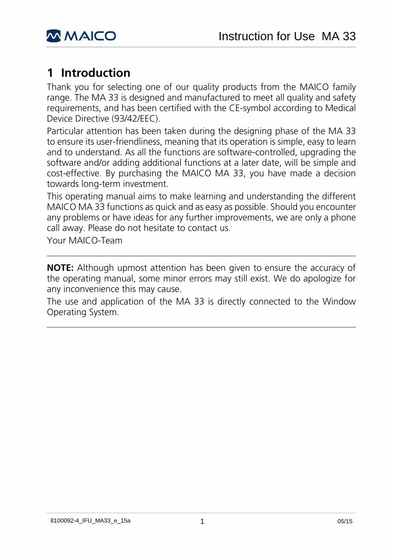
Figure 8
Figure 9

Instruction for Use MA 33
8100092-4_IFU_MA33_e_15a 12 05/15
Figure 10
Figure 11

Instruction for Use MA 33
8100092-4_IFU_MA33_e_15a 13 05/15
Figure 12
Figure 13
Instruction for Use MA 33
8100092-4_IFU_MA33_e_15a 14 05/15
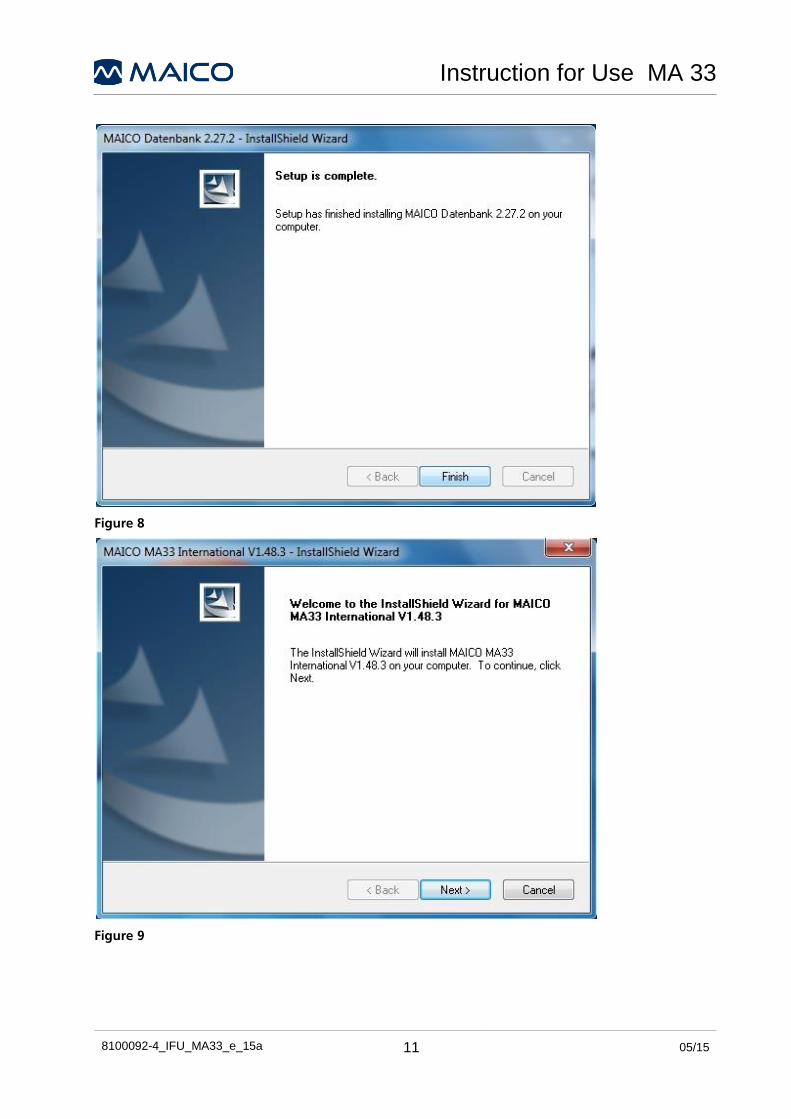
Figure 14
Figure 15

Instruction for Use MA 33
8100092-4_IFU_MA33_e_15a 15 05/15
Figure 16
Figure 17

Instruction for Use MA 33
8100092-4_IFU_MA33_e_15a 16 05/15
3.3 Installing the USB-Drivers
NOTE: In some cases (e.g. for users of Windows XP), it may be necessary to install the MA 33 USB driver additionally (Figure 18 to Figure 23).
Connect the MA 33 to the PC via the USB cable.
Figure 18
The installation wizard will appear. If not, it may be necessary to restart Windows. Please follow the steps as described below:
Figure 19
Select „Install Software Automatically (Recommended)“ and click „Next“.

Instruction for Use MA 33
8100092-4_IFU_MA33_e_15a 17 05/15
Figure 20
Figure 21

Instruction for Use MA 33
8100092-4_IFU_MA33_e_15a 18 05/15
Figure 22
To complete the installation, click “Finish”. The USB driver is now installed.
Figure 23

Instruction for Use MA 33
8100092-4_IFU_MA33_e_15a 19 05/15
4 Working with the MA 33 Start the patient database, load the patient to be tested, and then start the MA 33 software.
The program´s start screen is displayed below (refer to Figure 24). Slight differences in settings and functionality will be apparent depending on the specific version (i.e. MA 33, MA 33 SISI or MA 33 Speech).
Figure 24
4.1 Operation with Mouse and Keyboard
The MA 33 is easily operated with the mouse by simply pointing and clicking on the required button or input field on the screen.
4.2 Different Keyboard Function Keys
The following is a list of different key combinations which allow for quick operation (i.e. key shortcuts):

Instruction for Use MA 33
8100092-4_IFU_MA33_e_15a 20 05/15
F1 Help
F2 Switching Tone/Speech
F3 Switching between left and right
F4 On/off for the right ear masking
F5 Air Conduction
F6 Bone Conduction (only for BC, SISI and Speech Version)
F7 Not used
F8 Pulse tone on/off
F9 On/off for left ear masking
F10 >100 dB
F11 UCL + MCL (toggeln)
F12 Interrupter/presenter Mode
TAB Switching between left/right ears
Ctrl (right) Activates Interrupter/Presenter for active channel
Ctrl (left) Activates Interrupter/Presenter for active channel
Spacebar Interrupter/Presenter adjustment for the active ear
Alt+D Delete measurement
Alt+L Load available measurement
Alt+N New (NOAH)
Alt+S Save measurement
Alt+X Exit program
Alt+U Marking of uncertain hearing
B Binaural
Alt+T Settings
Alt+E Edit
Alt+C Screening
L Left ear
R Right ear
Alt+R Print
? Marking of unclear curves
↑↓ Volume control for the testing ear
Home Return to 1kHz
Page↑↓ Volume control for the opposite ear
Del Delete last measurement

Instruction for Use MA 33
8100092-4_IFU_MA33_e_15a 21 05/15
SISI-Test
S Start/Stop (Player)
P Start (Player)
E End of SISI-Test
Alt+W Warble tone
Alt+P Pulse tone

Instruction for Use MA 33
8100092-4_IFU_MA33_e_15a 22 05/15
5 Tone Audiometry
Figure 25
The following settings are displayed after opening the tone screen (Figure 25).
Default setting: right channel is set to air conduction pure tone and the left channel is inactive (i.e.“OFF” is displayed until the channel is turned on). The frequency is automatically set to 1 kHz. (Any of these settings may be changed by using the mouse or keyboard shortcuts.)
The start screen displayed above, is an example of the tone audiometry screen. The grey shadows in the lower area of the audiogram, mark the level limits of the selected transducer. The MA 33 tone audiometry software supports (depending on the instrument version) the main tone audiometric testing methods. The following testing methods can be started from the tone audiometry screen and documented in the software:
Method Version
Air conduction All
Hughson Westlake Test Optional
Bone conduction MA 33 BC, SISI, Speech
Most Comfortable Hearing Level (MCL) All
Uncomfortable Hearing Level (UCL) All
Stenger Test All
SISI-Test MA 33 SISI, Speech

Instruction for Use MA 33
8100092-4_IFU_MA33_e_15a 23 05/15
Button Function
Client Name selected from the patient database is displayed here
Examiner Name chosen at start of module is displayed here and on printout
Autotest Hughson Westlake patient controlled automatic threshold test
L / B / R Select left, both or right ear
SISI Only MA 33 SISI or Speech. Opens the SISI-test start screen
Talk Forward Makes the MA 33 easy to work with particularly in sound booth installations.
Speech Selects speech audiometric screen
Status bar The status bars show signal (i.e. tone or noise), frequency and level for each side
Interrupter mode Click here to switch between presenter and interrupter mode
>100 dB Allows stimulus presentation above 100 dBHL
Phones Stimuli will be presented through headphones
Bone Stimuli will be presented through bone oscillator
MCL Tests Most Comfortable Hearing Level, displays stored score as MCL in data table
UCL Tests Uncomfortable Hearing Level, displays stored score as UCL in data Table
No Response Stimulus not heard by patient - Stores threshold with a “No Response” symbol
Uncertain Uncertainty if stimulus was heard by patient - Stores threshold with a “uncertain” symbol
Pulse tone If required, the test can also be performed with a pulsed tone.
Warble tone If required, the test can also be performed with a warble tone.
Masking Activates Masking

Instruction for Use MA 33
8100092-4_IFU_MA33_e_15a 24 05/15
Stenger: Activates binaural mode to conduct and score Stenger test
PTA: Displays Pure-Tone Average from tone screen (Figure 26)
Track Activates the masking noise to automatically increase and decrease the level in relation to the signal. It also increases and decreases the other ear, in binaural mode.
Lock Locks presentation of the signal in both channels together, so they will both be presented at the same time using only one presentation key.
Level and frequency of masking and level and frequency of SISI-test (i.e. right side see below) will be stored and displayed in the following table (Figure 27):
To start further processing of your measurement press the appropriate button (Figure 28).
Figure 28
Delete: Delete the previous measurement.
Load: Load a previously stored measurement. The loaded wave will be displayed in different color.
Save: Save current measurement.
Screening: Screening Test with 20 dB.
Settings: Different setting options are available.
Print: Prints directly.
Exit: End the Program.
Remarks: Comments and additional remarks can be added here.
Connection Status: Indicates if the instrument is properly connected to the PC.
Figure 27
Figure 26

Instruction for Use MA 33
8100092-4_IFU_MA33_e_15a 25 05/15
5.1 Setting
The option „Setting“ allows the following different setting options to be modified: view, masking, operation, function key, frequencies and settings (Figure 29).
Figure 29
The setting can be changed by clicking on the different setting options. Click “OK” to apply the new setting.

Instruction for Use MA 33
8100092-4_IFU_MA33_e_15a 26 05/15
5.1.1 Display
Combined Audio: Changes display. The combined audiogram displays both ears, together on one audiogram.
R < > L: Choose the side of the screen on which the right and left channel are to appear.
Degrees HL: Displays sample categories for different degrees of hearing loss on the audiogram.
Edit: Activates the “Edit” button on the display (Figure 30).
5.1.2 Masking
The masking function is by default „Automatic“.
Different intensities of masking can be entered directly, when “Automatic” masking is activated.
Manually: Enables masking level to be adjusted manually during testing.
In Graph: To view the masking setting graphically, click „In Graph“ (Figure 31).
5.1.3 Operation
Mouse: once activated, enables the user to control volume setting by using the mouse. Volume is adjusted per mouse by clicking on the level in the left or right audiogram, depending on the channel being tested.
Audio-Keyboard: the function keys of the Audio-Keyboard will be activated when an Audio-Keyboard (additional accessories) is connected to the computer.
Interrupter: Switch to interrupter mode.
Presenter: Switch to presenter mode.
Store value by interrupt (Figure 32).
Figure 31
Figure 32
Figure 30

Instruction for Use MA 33
8100092-4_IFU_MA33_e_15a 27 05/15
5.1.4 Function Key
Screening 20 dB: By clicking this button, a screen opens and enables the user to conduct screening tests at different decibel levels. Moving the decibel bar increases or decreases the tone intensity used for screening. Default is set at 20 dB.
Level Settings: With this function key, the level at which the test starts can be changed from –10 dB to 0 dB. The standard validated level is set at –20 dB and can be set between 0 dB and –40 dB.
Help: Operating manual.
Info: Shows information such as serial number and software version (Figure 33).
5.1.5 Frequency
Block-/PTA-Freq: Certain frequencies can be blocked and hence will be skipped during audiometric testing (this does not apply when a mouse is used).
Step by : If you use the “Enter“ key to confirm the data, the cursor “steps” to the next frequency (i.e. either to the left or to the right in the audiogram) depending on whether you decide to test the lower frequencies (i.e. < 1 kHz) first or the higher frequencies (i.e. > 1 kHz) first.
Auto Settings: When wrapping is activated, instead of returning to 1 KHz at the end of the frequency range, the cursor will return to the start of the frequency range, as if circulating the frequency range.
Safety Function: The safety function prevents an immediate increase in the frequency level to exceed 70 dB, during frequency change (Figure 34).
Figure 33
Figure 34

Instruction for Use MA 33
8100092-4_IFU_MA33_e_15a 28 05/15
5.1.6 Settings
Permanent pulse: Permanent pulse can be activating by clicking the button.
Binaural: Binaural measurement can be performed in addition to single left or right ear measurement.
Print: Offers different print settings such as Color Print (Standard Setting B/W), DIN A5 (Standard A4) and other print options. Patient’s contact details can be added under „Address/Phone“.
Evaluation: Setting for a pure evaluation workstation (no device check).
Default Settings: All individual settings will be removed. Return to default settings (Figure 35).
5.1.7 General Function Keys
Figure 36
OK: By clicking „OK“, changes will be applied and the program returns to the start screen.
Ask for Examiner: In the event that more than one examiner is using the program, each examiner can save his/her customized settings for future use and reference.
When the program starts, enter the examiner´s name.
Cancel: Returns to start screen without saving the changed settings.
Examiner: Several different settings can be customized and saved for different examiners, should more than one examiner be using the MA 33 program.
Language: Displays current language (Figure 36).
Figure 35

Instruction for Use MA 33
8100092-4_IFU_MA33_e_15a 29 05/15
5.2 Performing tone audiometric tests
The patient should sit at a distance of at least 1 m from the device.
Eliminate any obstructions which will interfere with the placement of the earphone cushions on the ear (i.e. hair, eyeglasses).
Ensure that the headphones are positioned correctly: Red side on the right, blue side on the left. Adjust the headband of the headphones so that the earphones are positioned at the correct height (i.e. the sound output grid exactly facing the ear canal).
Explain to the patient that he/she needs to press the patient response key as soon as he/she just hears the test tone. The patient will be presented with a series of soft tones; hence it is important to pay attention.
As soon as a tone is heard, even a very soft tone, the patient should respond by pressing the patient response key.
For hygienic reasons, it is important to clean the headphone ear cushions after testing.

Instruction for Use MA 33
8100092-4_IFU_MA33_e_15a 30 05/15
5.2.1 Air Conduction Threshold Measurement
Figure 37
The hearing threshold of the patient is measured in comparison to the normal hearing threshold for air conduction (Figure 37). The test starts on the ear with better hearing ability.
Default setting: right channel is set to air conduction pure tone and the left channel is inactive (i.e. “OFF” is displayed until the channel is turned on). The frequency is automatically set to 1 kHz. (Any of these settings may be changed by using the mouse or keyboard shortcuts.)
Select the ear to be tested either by mouse click or by pressing R (right ear) / L (left ear) on the keyboard.
The volume can be changed using the ↑↓ cursor or with the mouse.
The volume is displayed as markers in the audiogram, as well as numerical values above and on the outer sides of the audiograms.
The measuring frequency can be adjusted using the ← → cursor or per mouse click.

Instruction for Use MA 33
8100092-4_IFU_MA33_e_15a 31 05/15
The left click lowers the frequency, while the right increases it.
Test through the frequencies: start at 1 kHz; set the higher frequencies first then the lower frequencies.
Select the next frequency, increase the level again and proceed with presenting the test signal as described above.
Once a threshold value has been established, record the measured value by pressing the („Enter“ key) or use the centre mouse button. The appropriate symbol will be plotted on the audiogram.
Once all frequencies have been tested, choose the less capable ear and repeat the hearing threshold test. After the patient presses the patient response key (the audiogram for the left channel highlights blue, and the audiogram for right channel highlights red), confirm the response by either pressing the ∙ key or the center mouse button.
As soon as the patient responds to the tone and presses the patient response key, press the ∙ key or the center mouse button to confirm the response. This is displayed in the audiogram as a red marking, „O“ for the right ear and as a blue marking, „X“ for the left ear.
The hearing threshold can be measured several times, and each new measurement overwrites the previous one. The measured values are automatically incorporated into the threshold curve, if only one intermediate frequency is sampled.
Pulse tone
If required, the test can also be performed with a pulsed tone. Click on Pulse tone and the pure tone will change to a pulsing tone.
Warble tone
If required, the test can also be performed with a warble tone. Click on the button and the pure tone will modulate. The warble tone can also be pulsed as described above.

Instruction for Use MA 33
8100092-4_IFU_MA33_e_15a 32 05/15
5.2.2 Automatic Threshold Test (Hughson Westlake Option)
Another form of threshold search is using the Hughson Westlake automatic tests procedure, also known as the “10 down, 5 up” method.
To open the automatic test screen click the Autotest button (Figure 38):
Figure 38
Before starting the test it is useful to explain following directions regarding the hearing test to the test person: The test person will hear a series of soft “beeps” and should listen very carefully. The test person should press and release the response button as soon as he/she hears the sound, even if it is very soft. The test person will hear directions given through the earphones, and should listen to those carefully when they are presented.
Testing will begin in the right ear at 1000 Hz. “Right” will be highlighted and the cursor will indicate the level and frequency where the test will start.
Press the button in order to start the automatic Hughson Westlake test. If voice prompt is activated, the test person will hear an initial set of instructions in his/her headphones. Following these instructions, the test will immediately begin by presenting the first tone.

Instruction for Use MA 33
8100092-4_IFU_MA33_e_15a 33 05/15
If the test person does not respond by pressing the hand button, the tone intensity will increase for 5 dB. This will continue until the test person responds to the tone. When the test person presses the hand button in response to the tone, the level will decrease by 10 dB and then ascend in 5 dB steps until the patient responds again. This pattern of increasing by 5 dB and decreasing by 10 dB will continue until the patient has two out of three responses at a particular level.
After this threshold is established, it is displayed in the corresponding audiogram and stored as a numerical value in a table for the appropriate ear. The test will continue until all frequencies have been tested for both the right and the left ear.
Start/Pause and Stop the test (Figure 39).
ON” Activate Adoption start level to start with the previously recorded hearing threshold. “OFF” begins with the start level at next frequency (Figure 40).
“ON” will continue to test the next frequency after an error is recorded without stopping the test. “OFF” will pause the test after an error is recorded to allow the operator to intervene (Figure 41).
Possible errors: Multiple responses to a tone; continuously holding down the response button without releasing it; not responding at all to the tones even at the loudest level.
Repeat test on (Figure 42).
NONE: All frequencies will be tested only once for each ear regardless of errors.
Only 1 kHz: 1000 Hz will be retested in order to make sure that the patient’s responses are valid.
All Errors: Frequencies that have errors recorded instead of a threshold value will be retested at the end of the test.
Figure 39
Figure 40
Figure 41
Figure 42
Instruction for Use MA 33
8100092-4_IFU_MA33_e_15a 34 05/15
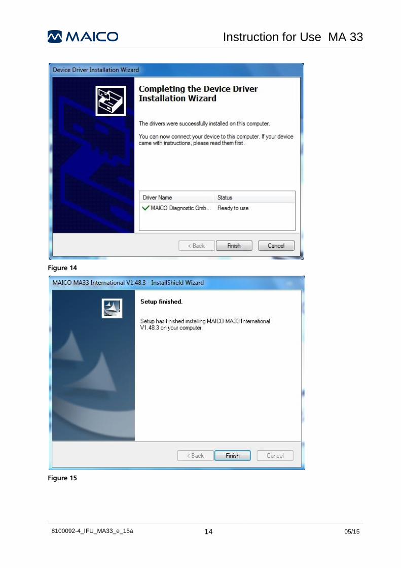
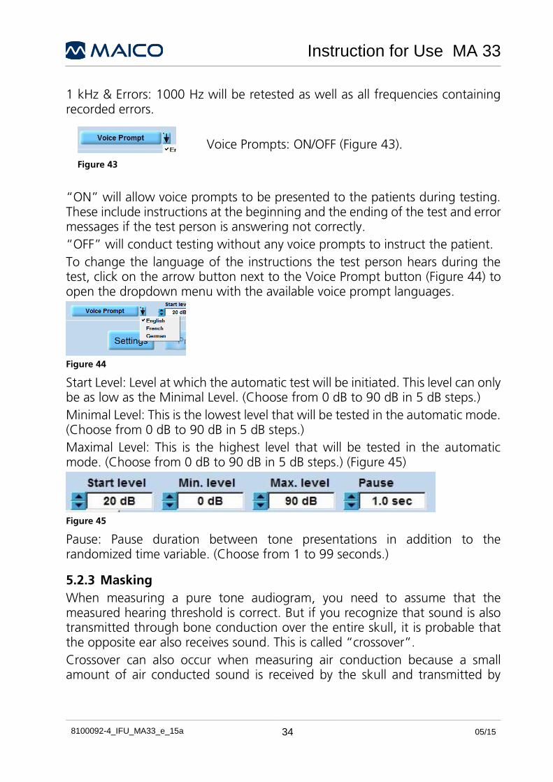
1 kHz & Errors: 1000 Hz will be retested as well as all frequencies containing recorded errors.
Voice Prompts: ON/OFF (Figure 43).
“ON” will allow voice prompts to be presented to the patients during testing. These include instructions at the beginning and the ending of the test and error messages if the test person is answering not correctly.
“OFF” will conduct testing without any voice prompts to instruct the patient.
To change the language of the instructions the test person hears during the test, click on the arrow button next to the Voice Prompt button (Figure 44) to open the dropdown menu with the available voice prompt languages.
Figure 44
Start Level: Level at which the automatic test will be initiated. This level can only be as low as the Minimal Level. (Choose from 0 dB to 90 dB in 5 dB steps.)
Minimal Level: This is the lowest level that will be tested in the automatic mode. (Choose from 0 dB to 90 dB in 5 dB steps.)
Maximal Level: This is the highest level that will be tested in the automatic mode. (Choose from 0 dB to 90 dB in 5 dB steps.) (Figure 45)
Figure 45
Pause: Pause duration between tone presentations in addition to the randomized time variable. (Choose from 1 to 99 seconds.)
5.2.3 Masking
When measuring a pure tone audiogram, you need to assume that the measured hearing threshold is correct. But if you recognize that sound is also transmitted through bone conduction over the entire skull, it is probable that the opposite ear also receives sound. This is called “crossover”.
Crossover can also occur when measuring air conduction because a small amount of air conducted sound is received by the skull and transmitted by
Figure 43

Instruction for Use MA 33
8100092-4_IFU_MA33_e_15a 35 05/15
bone. Whether the crossover signal can be heard by the opposite ear, depends on its inner ear function.
Relevant to crossover, is the sound level which is received by the opposite ear. The difference between the original test signal with the test ear and the received signal at the opposite ear is called “interaural attenuation”.
IMPORTANT NOTE: Please advise the patient to inform you with which ear he/she hears the test signal. In doing so, it will be easier to detect crossover.
To ensure that the patient does not experience crossover, you must mask the opposite ear. Masking increases the hearing threshold of the opposite ear.
Masking is done with a noise signal which is transmitted by the headphone. For pure tone audiometry, a narrowband noise is used. This noise changes its center frequency according to the frequency of the test signal.
Adjust the required masking level.
NOTE: For effective masking the masking sound is presented continuously. You can interrupt the masking signal by pressing the corresponding “Ctrl” key.
5.2.4 Edit Mode: Tone Screen
To enter Edit mode, click on Setting / View / Edit and save the changes. The Edit button is displayed in the middle part of the tone screen (refer to figure 36). Click on this button to activate the edit function. Once in Edit mode, the functions described below may be performed:
5.2.4.1 Deleting the last stored value
The last value stored can normally be quickly and simply deleted by pressing the “Delete” key on the keyboard. The user then needs to confirm with “Yes” to delete this last stored value, or “No” to not delete it and continue testing.
However, in order to delete additional values, the user must enter Edit mode (refer to figure 37, center of screen). This is a precautionary measure, so that data may not be unintentionally deleted from the main test screen.
5.2.4.2 Changing hearing thresholds on the audiogram
During a current test session, hearing threshold levels can normally be changed by simply moving the cursor to the place on the audiogram where the correct level needs to be and then by pressing “enter” key or centre mouse click. The stored symbol will move to this new level.

Instruction for Use MA 33
8100092-4_IFU_MA33_e_15a 36 05/15
However, if thresholds need to be completely deleted, and not just changed, then the user must enter the Edit mode.
5.2.4.3 Deleting Values in Tone Screen
To delete a threshold completely, select the transducer used and place mouse over the threshold. Right click on the mouse and make the appropriate selection: “Delete Value” or “Delete curve.” “Delete Value” will permanently remove only that one particular threshold point.
5.2.4.4 Adding Values in Tone Screen
Threshold values can also be added while in Edit mode. Select the transducer and if appropriate the type of testing (i.e. MCL, UCL, aided, etc.). This will ensure that the appropriate symbol is plotted. Left click on the audiogram with the mouse to plot a threshold value. To plot thresholds for the right ear, click on the right- channel audiogram. To plot thresholds for the left ear, click on the left-channel audiogram. There is no need to change ear selections while in edit mode.
5.2.5 Air Conduction Screening
Figure 46
Select „Screening“in the lower-middle part of the start screen (Figure 46).
Default setting: Intensity 20 dB (changeable under “Setting“, “Function Keys“, “Screening“), Frequency 1 kHz, pulse tone. The measurement will start with the right ear.
Test the frequency: begin at 1 KHz, then increase the frequency, confirm the patient´s response by pressing “enter” or the center mouse button and then continue with the next frequency.
The right l cursor increases the frequency while the left j cursor decreases the frequency.
The test tone can be interrupted by pressing the „spacebar”.
After the patient has pressed the patient response key, record the measured value by pressing the “enter” key or use the centre mouse button.
The red marking “O” in the audiogram is for the right ear and the blue marking “X” is for the left ear.

Instruction for Use MA 33
8100092-4_IFU_MA33_e_15a 37 05/15
5.2.6 Speech Therapy Mode (BPTA)
Using the „Binaural Puretone Audiometry“ (BPTA) you check at 20 dB and/or the auditory threshold, if the child hears the tone on the left, right or both sides. Activate BPTA-Mode by clicking Binaural in „Setting Tone“.
Figure 47
Transfer test results per mouse click to the according table. The index will automatically be calculated (Figure 47).
Figure 48
Utilization of BPTA mode (Figure 48):

Instruction for Use MA 33
8100092-4_IFU_MA33_e_15a 38 05/15
Click on the white area and choose red circle (meaning right), cross (meaning left) or circle with cross (for both).
The average results of the sum of the whole selection.
5.2.7 Bone Conduction Threshold (MA 33 BC, Speech)
Figure 49
Bone conduction, which involves the transmission of sound waves through the skull directly to the inner ear, provides information regarding the function of the inner ear. For a neural hearing loss, the values of air conduction and bone conduction are the same. In this case, a hearing loss of the middle ear can be eliminated.
Place the bone conduction transducer so that the flat, circular side of the transducer is positioned on the mastoid, on the noticeable ledge of the cranial bone behind the auricle. The other side of the headband is placed in front of the opposite ear.
Set the transducer selector to Bone (Figure 49).

Instruction for Use MA 33
8100092-4_IFU_MA33_e_15a 39 05/15
Perform the test in the same way as for air conduction.
5.2.7.1 Masking
For bone conduction measurement, the interaural attenuation is 0 to 15 dB. Bone conduction crossover is therefore possible even with a slight difference in hearing loss between ears.
IMPORTANT NOTE: Please advise the patient to inform you as to which ear he/she hears the test signal. In doing so, it will be easier to detect crossover.
Adjust the required masking level.
NOTE: For effective masking the masking sound is presented continuously. You can interrupt the masking signal by pressing the corresponding “Ctrl” key.
To mask when performing bone conduction testing: place the headphone on the opposite ear so that the earphone sits at the correct height (i.e. the sound output grid exactly faces the ear canal). Adjust the headband of the headphones, if necessary. Then place the transducer of the bone conductor on the mastoid of the test ear (i.e. on the noticeable flat area of the cranial bone behind the auricle).
5.2.8 Most Comfortable Listening Level (MCL)
Testing of MCL can be measured using pure-tone stimuli or speech. The purpose is to determine the most comfortable listening level for the patient for a given stimulus. The dB level at which the stimulus is the most comfortable is determined. This level might be described as, the level at which the patient would be comfortable listening for an extended period of time. Select MCL in order to test and store the Most Comfortable Listening Level.
5.2.9 Uncomfortable Hearing Level (UCL) Testing
Testing of UCL can be measured using pure tone stimuli or speech. The purpose is to determine the dB level at which the stimuli becomes uncomfortable for the patient. The UCL is described as the level between very loud and loud perception of the test signal. This information is valuable in determining the patient's upper dynamic range limit.

Instruction for Use MA 33
8100092-4_IFU_MA33_e_15a 40 05/15
Warning! Because this test uses high sound pressure levels, it is extremely important to perform this test using the utmost caution so as to avoid damaging the ear. To prevent the possibility of extreme discomfort for the patient, it is important to start the test with levels near the patients MCL (Most Comfortable Level).
Click UCL. The >100 dB field will be highlighted. Start testing with a test level of 60 dBHL. Present the tone briefly (max. 1s). If the signal was recognized by the patient as “not uncomfortable”, increase the level and proceed as described above. If the signal was uncomfortable for the patient, store the value. Proceed accordingly with other test frequencies.
5.2.10 SISI-Test (MA 33 SISI, Speech)
The SISI (Short Increment Sensitivity Index) is guided by the principle that patients with cochlear impairment are hypersensitive to small intensity increments. The continuous test tone is increased by 1 dB for a period of 0.2 seconds every 4.8 seconds. Whenever the patient hears the increment, he/she needs to press the patient response key. The SISI test information and the test score are shown on the display. The test will end automatically after 20 presented increments. The score is expressed as a percentage of ratio of the increments heard to the delivered increments (all increments heard = 100% - no increments heard = 0%). A high score indicates a cochlear impairment. A low score is related to normal hearing or conductive or retrocochlear pathology.

Instruction for Use MA 33
8100092-4_IFU_MA33_e_15a 41 05/15
5.2.10.1 Preparation of the SISI-Test
To start the test, click the SISI button on the top of the Screen. The SISI Test start screen opens (refer to Figure 50).
Click “R” or “L” to select the ear for testing:
Select the test frequency with the← → cursor.
For the test, you should choose the frequency at which the maximum bone conduction hearing loss was measured, as described in chapter 5.2.4.
Select the level with the ↑↓cursor.
The level should be set to a value 20 dB above the individual hearing threshold (which was attained during measurement as described in chapter 5.2.2). It must reach at least 60 dBHL.
Take note, that in the SISI mode, the tone for the test is presented continuously. You can interrupt the test by pressing S or by clicking on Stop. Press S or click Start to resume the test.
The patient must be instructed: "You will now hear a continuous tone. Every time it becomes louder, immediately push the switch”.
Figure 50

Instruction for Use MA 33
8100092-4_IFU_MA33_e_15a 42 05/15
5.2.10.2 Training of the Patient
Only with careful training during the following conditioning phase, can a valid test result be achieved.
Press the start button or <S> key to start the SISI-test.
The intensity starts automatically 20dB above measured threshold and can either be adjusted by clicking the ↑↓ arrows in the SISI box on the screen or the ↑↓ cursor keys.
For training purposes, the intensity increases by 5 dB every 5 seconds. For example, 60 dBHL to 65 dBHL .
Increment presentation is identified when the grey dot “lights up” and turns yellow on the screen (i.e. when tone is presented, the “given” dot lights up).
The dot indicates the time frame, within which the patient is allowed to respond to the increment (about 1.5 seconds). Any response that falls outside this time frame will not be registered, so as to exclude false responses.
When the patient presses the patient response key and thereby identifies that he/she has registered the tone, the “identified” dot lights up and turns green.
The number of detected (“identified”) increments is counted and shown on the display. Furthermore, the number of presented (“given”) increments is also shown.
When the patient has understood the procedure of the test, reduce the level to increase the increments to 3 dB, and subsequently to 2 dB, for further training and familiarization.
5.2.10.3 Performing the SISI-Test
Increase the intensity to 1 dB.
If the patient is responding correctly, start the SISI test with increments of 1 dB by clicking the start button. The following 20 signals will be presented with incremental intensity and the examiner can track the progress on test screen. The intensity increase can be prolonged by pressing the “spacebar”.
Once twenty increments have been presented, the test
stops automatically and the result will be displayed on the screen (Figure 51). The percentage of correctly-identified
increments, together with the total number of presented increments will be presented on the screen.
If the test result has reached a satisfactory level before twenty increments have been presented, the test can be terminated by pressing the “Stop” button.
Figure 51

Instruction for Use MA 33
8100092-4_IFU_MA33_e_15a 43 05/15
The SISI test can be ended and the result saved after ten increments have been presented, by clicking the „Exit“ button. The result will be shown automatically in the SISI table in the measuring screen. The total incremental ratio of SISI test is expressed as a percentage value.
A 25 % value indicates neural (auditory nerve) impairment, and sensory (inner ear) hearing impairment is indicated by a value greater than 70 %.
5.3 Pilot Hearing Test
The PILOT HEARING TEST is a fast and funny hearing test for children from the age of 2 years on. After a short training the children will play the Pilot game to get the “Pilot license”. A hearing test of speech recognition is included in the game. Severe hearing impairments can be detected at an early stage.
The child is asked, via headphones, to point to different pictures on the picture board: „Point to the ball“! During the following test the degree of difficulty will be increased step by step, as the test level decreases from 70 dBHL to finally 25 dBHL.
The PILOT HEARING TEST enables to test foreign-language children, as it is available in 26 different languages.
5.3.1 Licensing languages
Click on the „Pilot“ button, in order to license languages (see Figure 52 to Figure 57).

Instruction for Use MA 33
8100092-4_IFU_MA33_e_15a 44 05/15
Figure 52
The following screen (Figure 53) opens. Click on the Settings button, in order to continue.
Figure 53
Click on Info (Figure 54).

Instruction for Use MA 33
8100092-4_IFU_MA33_e_15a 45 05/15
Figure 54
In the opening window, click on Pilot Test License (Figure 55).
Figure 55
Please select your preferred language in the following window. Enter the code and click on the License button (Figure 56). The license code can be found on an additional sheet included in the delivery.

Instruction for Use MA 33
8100092-4_IFU_MA33_e_15a 46 05/15
Figure 56
When a green check mark appears, you can click on „Finish“ or „OK“ in order to return to the program (Figure 57).
Figure 57
The Language Licensing is now completed.
Instruction for Use MA 33
8100092-4_IFU_MA33_e_15a 47 05/15
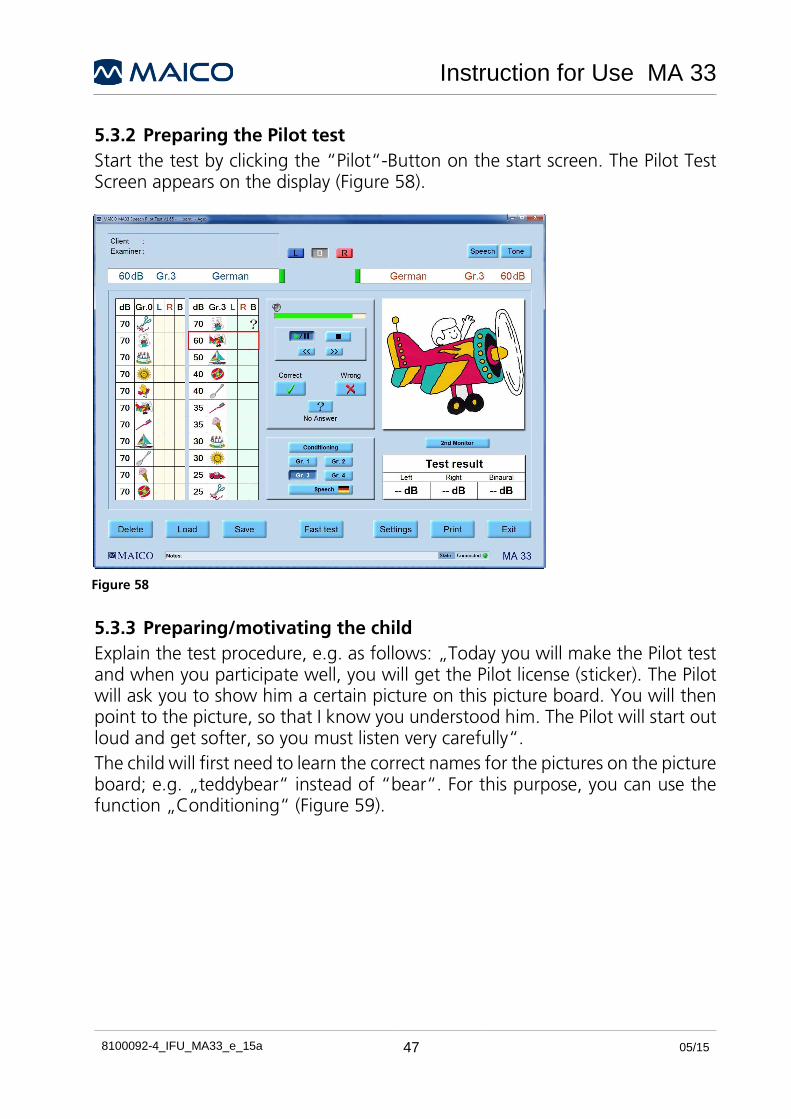
5.3.2 Preparing the Pilot test
Start the test by clicking the “Pilot“-Button on the start screen. The Pilot Test Screen appears on the display (Figure 58).
5.3.3 Preparing/motivating the child
Explain the test procedure, e.g. as follows: „Today you will make the Pilot test and when you participate well, you will get the Pilot license (sticker). The Pilot will ask you to show him a certain picture on this picture board. You will then point to the picture, so that I know you understood him. The Pilot will start out loud and get softer, so you must listen very carefully“.
The child will first need to learn the correct names for the pictures on the picture board; e.g. „teddybear“ instead of “bear“. For this purpose, you can use the function „Conditioning“ (Figure 59).
Figure 58

Instruction for Use MA 33
8100092-4_IFU_MA33_e_15a 48 05/15
Figure 59
Press the Pilot test START/PAUSE-Button to start the training with Group 0. The Pilot test language is displayed as small flag on the language button.
The child will hear the 11 following questions at a constant level of 70 dB. The corresponding pictures will be displayed for approval at the left side of the screen:
Point to the scissors Where is the teddybear
Point to the cake Where is the sun
Point to the bird Where is the airplane
Point to the toothbrush Where is the sailboat Point to the spoon
Where is the ice-cream Point to the ball
If you are not sure the child knows the words, point to the pictures and call them as they are called on the audiogram cards; e.g. „teddybear“ and not „bear“. To be sure that the child understands the questions, ask the child to identify the pictures in the same manner as the screening test, i.e. “Where is the teddybear“.
Instruction for Use MA 33
8100092-4_IFU_MA33_e_15a 49 05/15
Once you are confident that the child understands the test before all the 11 training words were spoken, you can finish the training by clicking the pilot test Start/Pause-button.
After a successful training you can start the pilot hearing test.
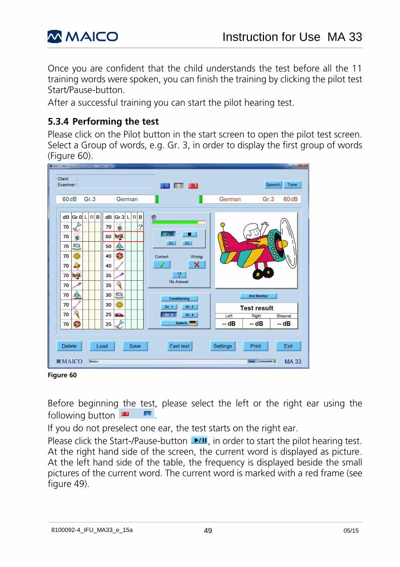
5.3.4 Performing the test
Please click on the Pilot button in the start screen to open the pilot test screen. Select a Group of words, e.g. Gr. 3, in order to display the first group of words (Figure 60).
Figure 60
Before beginning the test, please select the left or the right ear using the
following button .
If you do not preselect one ear, the test starts on the right ear.
Please click the Start-/Pause-button , in order to start the pilot hearing test. At the right hand side of the screen, the current word is displayed as picture. At the left hand side of the table, the frequency is displayed beside the small pictures of the current word. The current word is marked with a red frame (see figure 49).

Instruction for Use MA 33
8100092-4_IFU_MA33_e_15a 50 05/15
You can interrupt the test at any time by clicking the Start-/Pause-button . To restart the test, click the Start/Pause button again.
While the test is running, it is possible to repeat or to skip test sentences by clicking the Forward/Backward-buttons .
The test can be finished at any time by clicking the Stop-button .
The first sentence “Point to the ball“ will play at a level of 70 dBHL.
If the child points to the picture on the picture board that corresponds to the sentence, the examiner confirms the answer by clicking the Correct-button. This can be done by a mouse click or by the C-key on the keyboard.
If the answer was wrong, the examiner has to click the Wrong-button. This can be done by a mouse click or by pressing the W-key on the keyboard.
If there was no response at all, a question mark appears automatically in the table. This question mark appears also, when the examiner clicks the No-answer-button or the ?-key on the keyboard.
The test will go on to the next sentence „Where is the car?“ and the volume level decreases to 60 dBHL. The next picture is displayed on the screen. The test will continue with the next words of the Group 1 and decreasing levels.
The results are shown in the table (Figure 61).
Figure 61

Instruction for Use MA 33
8100092-4_IFU_MA33_e_15a 51 05/15
Figure 61
The level at which the patient correctly understood the sentence is shown on the display. This level is saved under „Test result“ beside the respective ear and is displayed on the screen (see figure 50).
Instead of the picture board you can also use the optional touch screen. You can get to the optional touch screen by clicking on the button “2nd Monitor” (see figure 50). It allows answering the test questions by touching the right picture on the screen. If the little patient touches the correct picture, a green check mark appears in the table. If the patient touches the wrong picture, a red cross is displayed meaning “wrong answer”. If the child does not touch a picture at all, a question mark is displayed in the table.
Choose a different test group for the second ear, so that the patient does not get too familiar with the test. Do this by clicking on the correspondent Group-button (see

Instruction for Use MA 33
8100092-4_IFU_MA33_e_15a 52 05/15
Figure 61). There are four different groups of test words/sentences at your disposal (Figure 62).
Figure 62
The test continues after the confirmation of the examiner (correct/incorrect). You can change the pause length between the sentences by selecting the pause length from the drop down menu “Interval” (3-20 seconds or Correct/Incorrect) in the Speech test start screen (Figure 63).
Figure 63
The „Fast test“ button allows performing a short hearing test, beginning at 40 dBHL (Figure 64).

Instruction for Use MA 33
8100092-4_IFU_MA33_e_15a 53 05/15
Figure 64
Please click on the Save button in order to save the test results. When you click on the Exit button, you are asked if you want to save the test results (Figure 65).
Figure 65
Saved test results can be recalled by clicking the Load button.
5.3.4.1 Testing both ears (binaural)
The binaural presentation allows testing both ears at once (binaural). For this purpose, please click on the “Settings” button. Select “binaural” in the opening menu. Afterwards, please click on “OK“ (see Figure 66).

Instruction for Use MA 33
8100092-4_IFU_MA33_e_15a 54 05/15
Figure 66
Binaural testing must first be enabled by clicking the „B“ button in the upper screen. The test will then be presented on both ears (Figure 67).
Figure 67

Instruction for Use MA 33
8100092-4_IFU_MA33_e_15a 55 05/15
6 Speech Audiometry (MA 33 Speech) As part of the MA 33 Speech software you are able to enter the speech audiometry tests by pressing “F2” on the keyboard or by clicking on the Speech button in the top, right-hand corner of the tone audiometric screen (Figure 68).
To conduct speech tests you can use a microphone, wave files or CD-ROM.
Figure 68

Instruction for Use MA 33
8100092-4_IFU_MA33_e_15a 56 05/15
Button Function
L / B / R Select left, both or right ear
Phones Stimuli will be presented through headphones
Microphone To conduct speech test by microphone
Wave File To conduct speech test by wave file
CD-Rom To conduct speech test by CD-ROM
>100 dB Allows presentation above 100 dBHL
Talk Forward To adjust the talk forward volume
Track Activates the masking noise to automatically increase and decrease level in relation to the signal
Lock Locks presentation of the signal in both channels together so they will both be presented at the same time using only one presentation key.
Masking Activates Masking
SRT Speech-reception threshold, displays stored score as SRT in data table
SAT Speech-awareness threshold, displays stored score as SAT in data table
WRS Word-recognition score, displays the stored score in the table
MCL Tests Most Comfortable Hearing Level, displays stored score as MCL in data table
UCL Tests Uncomfortable hearing Level, displays stored score as UCL in data Table
Reset Resets the word table
Interval Select the amount of time (in seconds) between word presentations, when using the wave files included in the software.

Instruction for Use MA 33
8100092-4_IFU_MA33_e_15a 57 05/15
Figure 69
Speech test player: Choose word group, start/pause test, go to previous / next word, stop test (Figure 69).
Figure 70
Stenger: Activates binaural mode to conduct and store result of Stenger Test.
PTA: Displays Pure-Tone Average from tone screen (Figure 70).
Figure 71
Click the corresponding buttons to record the response and to allow test results to be displayed in the Speech Audiometric Table (Figure 71).
Columns shown in speech audiometry table (Figure 72).
SRT db HL, level at which speech reception threshold is obtained
SAT db HL, level at which speech awareness threshold is obtained test ear during an SRT/SAT test
Mask dB HL, level of masking noise presented
MCL dB HL, value obtained for most comfortable listening level to speech
UCL dB HL, value obtained for uncomfortable listening level to speech
Condition/Word List
lists transducer, ear, and lists what was presented
Notes – the user may type comments into this field
% percent correct score obtained for a word recognition (discrimination) test.
Signal dB HL, level at which a word list was presented to the test ear for a word recognition (discrimination) task
Mask – dB HL, level of masking noise presented to the non test ear during a word recognition (discrimination) task
SNR loss Value calculated from the results of the QuickSIN test.
Figure 72

Instruction for Use MA 33
8100092-4_IFU_MA33_e_15a 58 05/15
If Wave file is selected, a speech list is displayed on the screen (Figure 73).
Delete: Delete the previous measurement.
Load: Load a previously stored measurement (i.e. test result). The loaded wave will be displayed in different color.
Note: After loading a previous measurement, the tone screen appears on the display! To go back and view the loaded measurement, select the “Speech” button in the top, right-hand corner of the tone screen.
Save: Save current measurement.
Settings: Different setting options are available.
Print: Prints directly.
Exit: End the Program.
Remarks: Comments and additional remarks can be added here.
Connection Status: Indicates if the instrument is properly connected to PC.
See Figure 74.
Figure 74
Figure 73

Instruction for Use MA 33
8100092-4_IFU_MA33_e_15a 59 05/15
6.1 Setting
The option „Setting“, allows different setting options to be modified for the following: view, counter, operation, information, functionality and settings (Figure 75).
Figure 75
The setting can be changed by clicking on the different setting options. Click “OK” to apply the new setting.

Instruction for Use MA 33
8100092-4_IFU_MA33_e_15a 60 05/15
6.1.1 Display / View
R < > L: Choose on which side of the screen the right and left channel are to be displayed.
Edit: Activates the “Edit” button on the display.
Graph Axis: Choose between dBHL and dBSPL (Figure 76) see also Figure 78 und Figure 77).
6.1.2 Counter
Relative: Displays the correct score result of a word list as a percentage, relative to the number of words presented to the patient.
Absolute: Displays the correct score result of a word list as a percentage, in reference to the absolute (i.e. total) number of words (Figure 79).
6.1.3 Operation
Mouse: once activated, enables the user to control volume setting by using the mouse. Volume is adjusted per mouse by either: clicking on the level in the corresponding audiogram or by pressing the arrows in the top left-hand corner or top right-hand corner of the screen, depending on the channel (Figure 80).
Figure 76
Figure 80
Figure 78 Figure 77
Figure 79

Instruction for Use MA 33
8100092-4_IFU_MA33_e_15a 61 05/15
Audio-Keyboard: the Audio-Keyboard function keys are activated when an Audio-Keyboard (additional accessories) is connected to the computer.
6.1.4 Information
Help: Operating manual
Info: Shows information such as serial number and software version (Figure 81).
6.1.5 Functionality
Switching Ear: Keep level and noise or Reset level, switch off noise (default) when switching ears (Figure 82).
6.1.6 Settings
Level control: (default) when the level control is activated and the tester changes the level during the speech test, a warning dialog box appears.
Binaural: Binaural measurement can be performed individually or simultaneously.
Print: Offers different print settings such as Color Print (Standard Setting B/W), DIN A5 (Standard A4) and other print options. Patient’s contact details can be added
under „Address/Phone“.
Evaluation: Setting for a pure evaluation workstation (no device check).
Default Settings: All individual settings will be removed. Return to default settings (Figure 83).
Figure 81
Figure 82
Figure 83

Instruction for Use MA 33
8100092-4_IFU_MA33_e_15a 62 05/15
6.1.7 General Function Keys
OK: By clicking „OK“, changes will be applied and the program returns to start screen.
Ask for Examiner: In the event that more than one examiner is using the program, each examiner can save his/her customized settings for future use and reference.
When the program starts, enter the examiner´s name.
Cancel: Returns to start screen without saving the changed settings.
Examiner: Several different settings can be customized and saved for different examiners, should more than one examiner be using the MA 33 program.
Language: Displays current language (Figure 84).
6.2 Performing the Speech Test
The speech-recognition threshold SRT is the hearing threshold for speech. It is the lowest level at which the patient correctly recognizes the stimuli 50% of the time. Usually, recognition is indicated by repetition of the speech-stimulus item. The speech test can be done with recorded speech test material from CD or Wave File or with the microphone and live voice using standardized word lists. Different methods for speech tests are standardized worldwide such as the ASHA guidelines for determining the threshold level for speech.
After entering the speech screen, select the source and method of speech generation (Microphone, Wave File, CD-ROM). Also choose what type of measurement you would like to store (SRT, WRS, MCL, etc.)
Explain to the patient that he should repeat each word he hears. The patient should sit at a distance of at least 1 m from the device. Eliminate any obstructions which will interfere with the placement of the earphone cushions on the ear (i.e. hair, eyeglasses).
Ensure the headphones are put on correctly: Red side on the right, blue side on the left. Adjust the headband of the headphones so that the receivers are at the correct height (the sound output grid exactly facing the ear canal)
Perform the test words.
Figure 84

Instruction for Use MA 33
8100092-4_IFU_MA33_e_15a 63 05/15
Score the patient´s response for each word using the CORRECT and INCORRECT buttons located at the right-hand, bottom corner of the speech screen (Figure 85). If Wave File is selected a correct response will be highlighted
in green and an incorrect response will be highlighted in red. At the end of the test, the test finishes automatically. Save the test score by clicking on the STORE key in the control panel. Information about the test will then be stored in the data table on the right side of the screen.
The scored word lists are saved as part of the patient’s record and can be viewed by clicking on the appropriate list stored in the data table (Figure 86). If you use Wave File this full list will then be displayed in the Word list and the list can be reviewed.
To change the level of the currently active signal, use the ↑↓ keys.
To change the level of the currently active signal in binaural mode:
Right ear: right mouse click in the audiogram or use the ↑↓ keys.
Left ear: left mouse click in the audiogram or use the “Page Up/Page Down” cursors.
6.2.1 Live speech test
To perform the live speech test with microphone, click on Microphone (Figure 87).
Before you start the live speech test you should calibrate the microphone.
To calibrate the microphone position yourself the customary distance from the microphone and speak test words.
Move the slider above the Microphone button to adjust the level until both VU-meters show all yellow and maximum one green light. If one or more red lights are on, reduce the level.
After preparing the test person start the presentation by speaking the test words.
Figure 86
Figure 87
Figure 85

Instruction for Use MA 33
8100092-4_IFU_MA33_e_15a 64 05/15
6.2.2 Speech test with Wave File
After preparing the test person select a speech list to be displayed on the screen using the buttons on the left side of the speech test player control panel.
Start anywhere in the word list by clicking on the word with which to start (It will highlight grey).
Arrows displayed in the lower right corner of the word list box, can be used to scroll to another part of the list.
Start the presentation by clicking the Play/Pause button on the speech test player control panel (Figure 88).
6.2.3 Speech test with CD-ROM
Put your CD with the recorded speech test material into the CD-ROM drive and click on the CD-ROM button.
The MA 33 must be calibrated to the particular speech test material in use to ensure valid test levels. That means every time you change the CD you must recalibrate the instrument. Click on Calibration next to the CD-ROM button and the calibration panel opens (Figure 89).
Figure 89
On every CD with speech test material should be a calibration track with a calibration noise.
Choose calibration track, select the channel and click on play.
Figure 90
Change the Amplitude with the left and right arrow buttons until the yellow and one green light of the VU-meter lights up (Figure 90). If one or more red lights are on, reduce the amplitude. Store the calibration by clicking OK.
After preparing the test person start the speech test and proceed as described above.
Figure 88

Instruction for Use MA 33
8100092-4_IFU_MA33_e_15a 65 05/15
Figure 91
You can choose any track directly by clicking on Track underneath the CD-ROM list (Figure 91). The length of the track is displayed next to the number.
Next tracks will be played automatically.
The chosen track will be repeated automatically.
6.3 Edit Mode: Speech Screen
To enter Edit Mode click on Settings / View / Edit and save the changes. The Edit button is displayed in the upper part of the speech screen (refer to figure 57). Click on the button to activate. Once in Edit Mode, the functions described below may be performed.
6.3.1 Deleting Values in Speech screen
To completely remove a stored value from the speech table, select the row in the table to be deleted by clicking in the “condition/word list” cell of that row. The entire row will highlight blue. Right-click on the mouse on the blue-highlighted cell “condition/word list.” A prompt box will appear asking if the value should be deleted. Click yes or no. Selecting “Yes”, will permanently remove the data in the blue-highlighted row. Selecting “No” will cancel the delete function, but will remain in Edit Mode.
6.3.2 Changing Stored Values in the Speech Screen
To change a stored value in the speech table, select the row in the table to be changed by clicking in the “condition/word list” cell of that row. The entire row will highlight blue. Then edit a response answer in the word list (see figure 57) and reselect the appropriate word with left mouse click, so as to display the changed response (i.e. highlight from green to red, or from red to green). This amendment will affect a change in the Speech Audiometric Table (see Figure 75).
Use the ↑↓cursor keys to change the level of the signal (WRS, MCL, UCL).
Activate the masking button (top right-hand corner of the screen) and use ”Page Up/Page Down” cursor on the keyboard, to change the level of the masker (SRT or WRS).

Instruction for Use MA 33
8100092-4_IFU_MA33_e_15a 66 05/15
7 Ownership, Warranty and Disclaimer
Ownership
The Audiometry Software (hereinafter referred to as „SOFTWARE“) is solely owned by MAICO Diagnostics GmbH, Sickingenstr. 70-71, D-10553 Berlin, Germany. By purchasing the SOFTWARE the buyer is entitled the right of usage, but not the ownership of the SOFTWARE. The SOFTWARE is to be used in accordance to the agreed terms of usage provisioned by MAICO.
Copyrights
MAICO’s ownership of the SOFTWARE covers worldwide and is therefore, protected against any unauthorized copying of the SOFTWARE. Non conformity use of the SOFTWARE is strictly prohibited.
Restrictions
You may not:
Reverse engineer or attempt in any manner to discover the source code of the Software.
Attempt to defeat any mechanisms in the software, including those mechanisms responsible for password protection of data and limiting the number of concurrent users.
Rent, lease, sublicense or in any manner, copy or transfer (except as permitted above) the Software.
Obscure or obliterate any MAICO copyright or trademark notices which appear on the Software, the documentation, the screen-display, or otherwise in connection with the Software.
MAICO specifically calls your attention to the fact that, any violation or infringement of above restrictions will result in legal action.
Limited Warranty
MAICO warrants you that any physical media and physical documentation provided by MAICO are free of defects in materials and workmanship. This limited warranty is effective for a period of ninety (90) days from the original purchase date. If MAICO receives notification within the warranty period of defects in materials or workmanship and determines that such notification is correct, MAICO will replace defective media or documentation. DO NOT RETURN ANY PRODUCT UNTIL YOU HAVE OBTAINED AUTHORIZATION TO DO SO FROM YOUR SUPPLIER. The entire and exclusive liability and remedy for breach of this limited warranty shall be limited to replacement of defective media or documentation supplied by MAICO, and shall not include or extend

Instruction for Use MA 33
8100092-4_IFU_MA33_e_15a 67 05/15
to any claim for or right to recover any other damages, including but not limited to, loss of profit, data, or use of the Software, or special, incidental or consequential damages, or other similar claims, even if MAICO has been specifically advised of possibility of such damages. In no event will MAICO’s liability for any damages to you or any other person ever exceed the lowest list price or the actual price paid for the license to use the software, regardless of the form of the claim.
Disclaimer
MAICO COVERS, INCLUDING BUT NOT LIMITED TO; ALL WARRANTIES, REPRESENTATIONS AND TERMS AND CONDITIONS, EITHER EXPRESSED OR IMPLIED; UNDER THE SPECIFIED TERMS OF USE AND APPLICATION OF THE SOFTWARE FOR ITS SPECIFIC PURPOSE. ALL OTHER TERMS AND CONDITIONS SHALL NOT APPLY.
Furthermore, MAICO does not guarantee that the SOFTWARE or Documentation is free of bugs, or fulfill the relevant standards, requirement or needs of a user. In this case, all the warranties, guarantees and terms and conditions on all MAICO delivered physical disk and documentation shall be limited to the 90 days warranty period.
MAICO is not liable for any third party’s product, disks, software or documentation that is used in conjunction with MAICO’s software or programs, but is not directly manufactured or supplied by MAICO.
General Terms and Conditions
Any change made to this Agreement shall be notified in writing, agreed and signed between both parties, namely the purchaser of the SOFTWARE and a representative of MAICO. In the event that the essential purpose of the above remedy (limited warranty) is not fulfilled, all other limited liability including the liability limits and exclusions of damage claims shall continue to apply
This Software License Agreement shall be interpreted and construed according to, and governed by, the laws of Jurisdiction of Republic of Germany.
In the event that any legal or commercial dispute or controversy arising out of, or relating to this agreement; provided MAICO is in all case violated of the rights, to the SOFTWARE or other intellectual property protection right related to the SOFTWARE; shall be presented under the Jurisdiction of Germany in the court of Berlin.
The SOFTWARE is protected under both Copyright Law and the International Copyright Treaties. Copying of the SOFTWARE is strictly prohibited except for copies made of the SOFTWARE for backup purposes to protect data loss.
Instruction for Use MA 33
8100092-4_IFU_MA33_e_15a 68 05/15
The SOFTWARE can be used by any number of users, on any number of computers, and in any place, provided that they are not on more than one display screen at the same time.
Warranty, Maintenance and After-Sales Service Hardware
The MA 33 audiometer is guaranteed for 1 year. This warranty is extended to the original purchaser of the instrument by MAICO through the Distributor from whom it was purchased and covers defects in material and workmanship for a period of one year from date of delivery of the instrument to the original purchaser.
The audiometer may be repaired only by your dealer or by a service center recommended by your dealer. We urgently advise you against attempting to rectify any faults yourself or commissioning non-experts to do so. Violating the mark of conformity voids all warranty claims. The device should therefore not be used before the next maintenance. In the event of repair during the guarantee period, please enclose evidence of purchase with the instrument. In order to ensure that your instrument works properly, the audiometer should be checked and calibrated at least once a year. This check-up needs to be conducted by your dealer.
When returning the instrument for repairs it is essential to also send the headphone, bone conduction receiver and other accessories. Send the device to your dealer or to a service center authorized by your dealer. Please also include a detailed description of the faults.
In order to prevent damage in transit, if possible please use the original packing when returning the instrument.

Instruction for Use MA 33
8100092-4_IFU_MA33_e_15a 69 05/15
8 Disinfection It is recommended that parts which are in direct contact with the patient (e.g. earphone cushions or patient response switch) are subjected to standard disinfecting procedure between patients. This includes physically cleaning and use of a recognized disinfectant. Individual manufacturer's instruction should be followed for use of this disinfecting agent to provide an appropriated level of cleanliness. If ear cushions are contaminated, it is strongly recommended to remove them from the transducer before they are cleaned.

Instruction for Use MA 33
8100092-4_IFU_MA33_e_15a 70 05/15
9 Safety Regulations
9.1 Electrical safety
The MA 33 is in compliance with Class BF of IEC 60601-1.
The instrument is not to be used in environments dealing with explosive material or equipment.
9.2 Measurement Safety
In order to ensure safety and quality of the measurement, an annual inspection and calibration should be performed. The annual check-ups can be performed by one of MAICO’s authorized service centers. MAICO will not be liable for any failure to comply with the specified inspection date, according to the Medical Product Law. The use of uncalibrated and uninspected audiometer is strictly prohibited.
9.3 Instrument Handling
The user of the instrument should perform a subjective instrument check once a week. This check can be done following the list for subjective instrument check (see page 77). For your own security, you should copy the enclosed list, fill it in once a week and store it in your files.
9.4 Operation
The instrument should only be handled and operated by trained personnel (audiologists, ENT doctors or personnel with similar qualifications).
9.4 Patient Safety
Please note that if connection is made to standard equipment like printers and network, special precautions must be taken in order to maintain medical safety. Connecting this device to other devices in order to make a system may cause the safety specifications to be invalid. It is therefore recommended to insert a galvanic separation between the device and the host computer, unless the computer is battery operated or supplied by a medical approved power supply. Galvanic separation must fulfill the IEC 60601-1.

Instruction for Use MA 33
8100092-4_IFU_MA33_e_15a 71 05/15
10 Technical Data Air Conduction
Intensity
Maximum level
Frequency 125
Hz
250
Hz
500
Hz
750
Hz
1 kHz
1.5 kHZ
2 kHz
3
kHz
4
kHz
6
kHz
8
kHz
TDH39 65 85 100 105 105 105 105 105 100 100 90
DD45 65 85 100 105 105 105 105 105 100 95 90
DD65 60 60 85 105 105 100 100 100 95 85 85
Holmco8103 85 95 100 110 110 110 110 110 105 85 85
Safety limit Intensity > 70 dBHV
Headphone DD 45 or optional DD 65 or TDH 39 or Holmco 8103
Audiometer Class Class 4 compliance with EN 60 645-1
Bone Conduction (MA 33 BC / MA 33 SISI):
Test frequencies
Maximum level
Frequency 125
Hz
250
Hz
500
Hz
750
Hz
1 kHz
1.5 kHZ
2 kHz
3
kHz
4
kHz
6
kHz
8
kHz
B71 - 30 60 65 70 70 70 70 70 50 -
Bone conductor B71 with headband
Audiometer Class Class 3 compliance with EN 60 645-1
SISI-Test:
Modulation Test signal 4,8/0,2s; 5dB, 3dB, 2dB (preparation), 4,8/0,2s; 1dB (Test)
Masking Band noise masking, manually or automatically adjustable
General Information:
Test signal Pure tone, Pulse and Warble tone
Test frequency 0,125; 0,25; 0,5; 0,75; 1; 1,5; 2; 3; 4; 6; 8 kHz
Intensity level 5 dB noise free

Instruction for Use MA 33
8100092-4_IFU_MA33_e_15a 72 05/15
Standards EN 60601-1, EN 60645-1
Instrument compliance with Directive 93/42/EWG for Medical Product Class II a
PC-connection USB 1.1 or 2.0
PC-System Windows 7 32/64bit Professional or Ultimate, Windows XP (SP2 or later)
Dimension MA 33 (W x L x H/ W): 15,4 x10,3 x 2,7 cm / 300 g
PC-System available on request
Figure 92
Connecting port: Connector assignment: Connection load:
Bone Conduction Headphone
Pole = Ground,
Tip = Contact
ZA= 4 Ω, UA= 5 Veff
Air Conduction Headphone L/R
Pole = Ground,
Tip = Contact
ZA= 10 Ω, UA= 1 Veff
Patient Response Key Pole = Ground,
Tip = Contact
RI= 500 Ω
PC-Connection 1 x USB- Entrance

Instruction for Use MA 33
8100092-4_IFU_MA33_e_15a 73 05/15
Calibration values: AC-Headphone TDH 39 Force 4-5 N
Frequency [Hz]
Reference equivalent threshold according to ISO 389-1 with coupler IEC 60318-3
RETSPL dB re 20μPa
125 45
250 25.5
500 11.5
750 7.5
1000 7
1500 6.5
2000 9
3000 10
4000 9,5
6000 15.5
8000 13
Speech* 4,5
*PTB standard
Calibration values: AC-Headphone DD45 Force 4-5 N
Frequency [Hz]
Reference equivalent threshold according to WDH Standard with coupler IEC 60318-3
RETSPL dB re 20μPa
125 47.5
250 27.0
500 13.0
750 6.5
1000 6.0
1500 8.0
2000 8.0
3000 8.0
4000 9.0
6000 20.5
8000 12.0
Speech 7.5

Instruction for Use MA 33
8100092-4_IFU_MA33_e_15a 74 05/15
Calibration values: AC-Headphone Radioear DD65 Force 10.1 – 11.1 N
Frequency [Hz]
Reference equivalent threshold according to WDH Standard with coupler IEC 60318-3
RETSPL dB re 20μPa
125 52.5
250 39.5
500 19.5
750 11.0
1000 8.5
1500 13.0
2000 9.0
3000 11.5
4000 10.5
5000 14.5
6000 29.0
8000 14.0

Instruction for Use MA 33
8100092-4_IFU_MA33_e_15a 75 05/15
Calibration: Optional AC headphone Holmco 8103 B 26 Pressure13...16 N
Frequency [Hz]
Equivalent Threshold Reference Level
according to
ISO 389-2
measured with Coupler
RETSPL dB re 20μPa
125 39.5
250 25
500 18.5
750 13.5
1000 12.0
1500 10.0
2000 9.5
3000 9.0
4000 9.0
6000 19.5
8000 20.0
Speech* 9.5
*PTB standard
NOTE: IEC 60645-2 sets the offset for speech audiometry levels between HL and SPL to 20 dB.
MAICO is using the PTB values for speech calibration since years.
Sample: The PTB offset value for DD45 is at 7,5 dB (IEC 30318-3), therefore this value needs to be deducted from the 20 dB standard difference.
Difference (HL/SPL MAICO) = 7,5 dB - 20 dB = -12,5 dB
By switching the MA 33 between HL and SPL mode will only change the output level according to that formular.

Instruction for Use MA 33
8100092-4_IFU_MA33_e_15a 76 05/15
Calibration: Bone Conduction Radio Ear B71 Headphone Pressure 4.9... 5.9 N
Frequency [Hz]
Equivalent Threshold Reference Level
according to ISO 7566
RETFL dB re. 1 μN (SK dB)
250 67.0
500 58.0
750 48.5
1000 42.5
1500 36.5
2000 31.0
3000 30.0
4000 35.5
6000 40.0
NOTE: The following frequencies are the differences between the emitted air noise of bone conduction headphone to that of the corresponding sound emitted by the human skull under specific sound intensity (mean value (maximum value)):
3 kHz: 4 dB (18 dB)
6 kHz: 10,5 dB (31 dB)

Instruction for Use MA 33
8100092-4_IFU_MA33_e_15a 77 05/15
Checklist for Subjective Audiometer Testing - Clean the ear and head cushion!
- Untangle all lines when necessary
- Are the headphone cushion in good condition?
If not replace
- Are plugs and leads in good condition/ undamaged?
- Are all controls working properly?
- Is the Patient Response Key working properly (if available)?
- Check batteries and renew if necessary?
Instrument:...................................... Manufacturer:…..............................
Serial No.:........................................ Examiner:........................................
Test Signal Quality
All the test frequencies in the below table indicate typical hearing level and can be changed when necessary: Masking: “B” for Buzz tone, “G” for Noise, “V” for signal distortion, “S” for switching masking noise.
Right Ear Level Left Ear
kHz 0,25 0,5 1 2 3 4 6 8 0,25 0,5 1 2 3 4 6 8 kHz
AC
30dB HL
50dB HL
70dB HL
BC 30dB HL
50dB HL
* When noise “B”, “G”, “V” or “S” is blocked, inform the service! * When the test tone is heard at the masking ear, contact the service!
Air Conduction Audiogram
Right Ear Level Left Ear
kHz 0,25 0,5 1 2 3 4 6 8 0,25 0,5 1 2 3 4 6 8 kHz
Should
dBHV*
Left Earpiece
Is
dBHV Left
Earpiece
Right Earpiece**
Is
dBHV
Right Earpiece **
* Should is the last measurement of the patient **For inverted measurement please reattach the headphone
If the frequency difference between „Should“ and „Is“ for one ear averages more than 10 dB, contact the SERVICE!
Bone Conduction Audiogram
Right Ear Level Left Ear
kHz 0,25 0,5 1 2 3 4 6 8 0,25 0,5 1 2 3 4 6 8 kHz
Should
dBHV*
Is
dBHV
If the frequency difference between „Should“ and „Is“ for one ear averages more than 10 dB, contact the SERVICE!
Tested.............................................................................................
Date:...............................................................................................

Instruction for Use MA 33
8100092-4_IFU_MA33_e_15a 78 05/15
Specifications are subject to change
MAICO Diagnostics GmbH Sickingenstr. 70-71 10553 Berlin Germany Tel.: + 49 30 / 70 71 46-50 Fax: + 49 30 / 70 71 46-99 E-mail: [email protected] Internet: www.maico.biz