instruction manual - alfa laval - united · pdf file · 2017-01-25instruction...
TRANSCRIPT
2050-0029
Patented Sensor SystemRegistered DesignRegistered Trademark
ESE02952-EN1 2016-10
Original manual
Instruction Manual
ThinkTop® Digital, AS-Interface and DeviceNet

Table of contents
The information herein is correct at the time of issue but may be subject to change without prior notice
1. EC Declaration of Conformity .. . . . . . . . . . . . . . . . . . . . . . . . . . . . . . . . . . . . . . . . . . . . . . . . . . . . . . . . . . . . . . . . . . . . . . 4
2. Safety ... . . . . . . . . . . . . . . . . . . . . . . . . . . . . . . . . . . . . . . . . . . . . . . . . . . . . . . . . . . . . . . . . . . . . . . . . . . . . . . . . . . . . . . . . . . . . . . . . . 52.1. Important information .. . . . . . . . . . . . . . . . . . . . . . . . . . . . . . . . . . . . . . . . . . . . . . . . . . . . . . . . . . . . . . . . . . . . . . . . . . . . 52.2. Warning signs .. .. . . . . . . . . . . . . . . . . . . . . . . . . . . . . . . . . . . . . . . . . . . . . . . . . . . . . . . . . . . . . . . . . . . . . . . . . . . . . . . . . . 52.3. Safety precautions .. . .. . . . . . . . . . . . . . . . . . . . . . . . . . . . . . . . . . . . . . . . . . . . . . . . . . . . . . . . . . . . . . . . . . . . . . . . . . . . 5
3. General information .. . . . . . . . . . . . . . . . . . . . . . . . . . . . . . . . . . . . . . . . . . . . . . . . . . . . . . . . . . . . . . . . . . . . . . . . . . . . . . . . . . 63.1. ThinkTop at a glance .. . . . . . . . . . . . . . . . . . . . . . . . . . . . . . . . . . . . . . . . . . . . . . . . . . . . . . . . . . . . . . . . . . . . . . . . . . . . 63.2. Recycling information .. . . . . . . . . . . . . . . . . . . . . . . . . . . . . . . . . . . . . . . . . . . . . . . . . . . . . . . . . . . . . . . . . . . . . . . . . . . . 6
4. Technical specifications ... . . . . . . . . . . . . . . . . . . . . . . . . . . . . . . . . . . . . . . . . . . . . . . . . . . . . . . . . . . . . . . . . . . . . . . . . . . . 74.1. ThinkTop common specifications .. .. . . . . . . . . . . . . . . . . . . . . . . . . . . . . . . . . . . . . . . . . . . . . . . . . . . . . . . . . . . . 74.2. ThinkTop Digital .. . . . . . . . . . . . . . . . . . . . . . . . . . . . . . . . . . . . . . . . . . . . . . . . . . . . . . . . . . . . . . . . . . . . . . . . . . . . . . . . . . 94.3. ThinkTop, AS-Interface .. . .. . . . . . . . . . . . . . . . . . . . . . . . . . . . . . . . . . . . . . . . . . . . . . . . . . . . . . . . . . . . . . . . . . . . . . . 104.4. ThinkTop DeviceNet . .. . . . . . . . . . . . . . . . . . . . . . . . . . . . . . . . . . . . . . . . . . . . . . . . . . . . . . . . . . . . . . . . . . . . . . . . . . . . 12
5. Installation .. . . . . . . . . . . . . . . . . . . . . . . . . . . . . . . . . . . . . . . . . . . . . . . . . . . . . . . . . . . . . . . . . . . . . . . . . . . . . . . . . . . . . . . . . . . . . 155.1. Installation on air actuators . . . . . . . . . . . . . . . . . . . . . . . . . . . . . . . . . . . . . . . . . . . . . . . . . . . . . . . . . . . . . . . . . . . . . . 155.2. Installation on Series 700 valves .. . .. . . . . . . . . . . . . . . . . . . . . . . . . . . . . . . . . . . . . . . . . . . . . . . . . . . . . . . . . . . . 175.3. Air connections .. . . . . . . . . . . . . . . . . . . . . . . . . . . . . . . . . . . . . . . . . . . . . . . . . . . . . . . . . . . . . . . . . . . . . . . . . . . . . . . . . . 195.4. Electrical connection, internal - Digital 24 VDC ... .. . . . . . . . . . . . . . . . . . . . . . . . . . . . . . . . . . . . . . . . . . . . 205.5. Example of using common power supply . . . . . . . . . . . . . . . . . . . . . . . . . . . . . . . . . . . . . . . . . . . . . . . . . . . . . . 205.6. Electrical connection, internal - AS-Interface ... . . . . . . . . . . . . . . . . . . . . . . . . . . . . . . . . . . . . . . . . . . . . . . . . 215.7. Electrical connection, internal - DeviceNet . . . .. . . . . . . . . . . . . . . . . . . . . . . . . . . . . . . . . . . . . . . . . . . . . . . . . 22
6. Setup diagram ... . . . . . . . . . . . . . . . . . . . . . . . . . . . . . . . . . . . . . . . . . . . . . . . . . . . . . . . . . . . . . . . . . . . . . . . . . . . . . . . . . . . . . . 236.1. ThinkTop setup- utilising local ’I’ and ’II’ keys .. . . . . . . . . . . . . . . . . . . . . . . . . . . . . . . . . . . . . . . . . . . . . . . . . 236.2. ThinkTop setup- utilising IR keypad .. . . . . . . . . . . . . . . . . . . . . . . . . . . . . . . . . . . . . . . . . . . . . . . . . . . . . . . . . . . . 266.3. ThinkTop quick setup guide .. . .. . . . . . . . . . . . . . . . . . . . . . . . . . . . . . . . . . . . . . . . . . . . . . . . . . . . . . . . . . . . . . . . . 28
7. Fault finding .. . . .. . . . . . . . . . . . . . . . . . . . . . . . . . . . . . . . . . . . . . . . . . . . . . . . . . . . . . . . . . . . . . . . . . . . . . . . . . . . . . . . . . . . . . . 307.1. Fault finding and LEDs .. . .. . . . . . . . . . . . . . . . . . . . . . . . . . . . . . . . . . . . . . . . . . . . . . . . . . . . . . . . . . . . . . . . . . . . . . . 30
8. Maintenance .. . .. . . . . . . . . . . . . . . . . . . . . . . . . . . . . . . . . . . . . . . . . . . . . . . . . . . . . . . . . . . . . . . . . . . . . . . . . . . . . . . . . . . . . . . 328.1. Dismantling ThinkTop .. . . . . . . . . . . . . . . . . . . . . . . . . . . . . . . . . . . . . . . . . . . . . . . . . . . . . . . . . . . . . . . . . . . . . . . . . . . . 328.2. Assembly of ThinkTop .. . . .. . . . . . . . . . . . . . . . . . . . . . . . . . . . . . . . . . . . . . . . . . . . . . . . . . . . . . . . . . . . . . . . . . . . . . . 338.3. Dismantling and assembling Series 700 valves .. . .. . . . . . . . . . . . . . . . . . . . . . . . . . . . . . . . . . . . . . . . . . . . 35
9. Parts list . . .. . . . . . . . . . . . . . . . . . . . . . . . . . . . . . . . . . . . . . . . . . . . . . . . . . . . . . . . . . . . . . . . . . . . . . . . . . . . . . . . . . . . . . . . . . . . . 379.1. Diagrams for ThinkTop .. . .. . . . . . . . . . . . . . . . . . . . . . . . . . . . . . . . . . . . . . . . . . . . . . . . . . . . . . . . . . . . . . . . . . . . . . . 379.2. ThinkTop .. . .. . . . . . . . . . . . . . . . . . . . . . . . . . . . . . . . . . . . . . . . . . . . . . . . . . . . . . . . . . . . . . . . . . . . . . . . . . . . . . . . . . . . . . . 389.3. Diagrams for ThinkTop: Series 700 .. . . . . . . . . . . . . . . . . . . . . . . . . . . . . . . . . . . . . . . . . . . . . . . . . . . . . . . . . . . . 419.4. ThinkTop: Series 700 .. . . . . . . . . . . . . . . . . . . . . . . . . . . . . . . . . . . . . . . . . . . . . . . . . . . . . . . . . . . . . . . . . . . . . . . . . . . . 42
3
1 EC Declaration of Conformity
Revision of Declaration of Conformity 2009-12-29
The Designated Company
Alfa Laval Kolding A/SCompany Name
Albuen 31, DK-6000 Kolding, DenmarkAddress
+45 79 32 22 00Phone No.
hereby declare that
Top Unit for Valve Control and IndicationDesignation
ThinkTop® Digital 24 VDC
ThinkTop® AS-Interface
ThinkTop® DeviceNet TM
Type
is in conformity with the following directive with amendments:
- EMC Directive 2014/30/EU- RoHS2 Directive 2011/65/EU
The person authorised to compile the technical file is the signer of this document
Global Product Quality ManagerPump, Valves, Fittings and Tank Equipment Lars Kruse Andersen
Title Name
Kolding 2013-12-03Place Date Signature
4

2 Safety
This manual highlights unsafe practices and other important information are emphasised in this manual.Warnings are emphasised by means of special signs. All warnings in the manual are summarised on this page.Pay special attention to the instructions below in order to avoid severe personal injury or damage to the top unit are avoided.
2.1 Important information
Always read the manual before using the top unit!
WARNINGIndicates that special procedures must be followed to avoid serious personal injury.
CAUTIONIndicates that special procedures must be followed to avoid damage to the ThinkTop.
NOTEIndicates important information to simplify or clarify procedures.
2.2 Warning signs
General warning:
Dangerous electrical voltage:
Caustic agents:
2.3 Safety precautions
Installation:
Always read the technical data carefully !Never install the ThinkTop before the valve or relay are in a safe positionIf welding close to the ThinkTop: Always perform earthing close to the welding areaDisconnect the ThinkTop.
Always ensure the ThinkTop electrically connected by authorised personnel
Maintenance:
Always read the technical data carefully !Always fit the seals between the valve and ThinkTop correctlyNever service the ThinkTop before the valve or relay are in a safe positionNever service the ThinkTop when the valve/actuator under pressureNever clean the ThinkTop using high pressure cleaning equipment
Never use cleaning agents that will erode the exterior of the ThinkTop. Check with your cleaning agent supplier
5

3 General information
3.1 ThinkTop at a glance
The ThinkTop is designed to ensure optimum and reliable valve control in conjunction with Alfa Laval valves and is compatiblewith most PLC systems (Programmable Logic Controllers).
The ThinkTop can be equipped with 0-3 solenoid valves. The solenoids are electrically controlled by the PLC system and, whenactivated, the compressed air is activating the air actuator. Depending on the type of control unit, the primary solenoid valve canbe provided with a built-in throttle function on both the air inlet and outlet, which means that it is possible to control the openingand closing time of the air actuator. The solenoids are also equipped with a manual hold override.
Visual LED lights constantly indicate the distinct status of the control unit: such as valve positions, solenoid valve energised,setup and local fault indication etc.
The ThinkTop is characterised by its high durability, well-proven features and modular design. It is exchangeable and is ready tofit Alfa Laval Sanitary actuators from the past and present.
3.2 Recycling information
• Unpacking
- Packing material consists of wood, plastics, cardboard boxes- Wood and cardboard boxes can be reused, recycled or used for energy recovery- Plastics should be recycled or burnt at a licensed waste incineration plant
• Maintenance
- All metal parts should be sent for material recycling- Worn or defective electronic parts should be sent to a licensed handler for material recycling- All non-metal wear parts must be handled in compliance with local regulations
• Scrapping
- End-of-life, the equipment shall be recycled according to relevant, local regulations. In addition to the equipment itself, anyhazardous residue from the process liquid must be taken into account and handled in the necessary way. When in doubt, orin the absence of local regulations, please contact the local Alfa Laval sales company
6

4 Technical specifications
4.1 ThinkTop common specifications
Sensor SystemUnique “No Touch” sensor system with no mechanical sensor adjustments. A magnet (indication pin) is mounted on the valvestem and the translatory change in the magnetic field vectors are detected by the sensor board with a measuring accuracyof ± 0.1mm.
Electrical connection:Direct main cable gland entry (hard wired) PG11 (ø4 - ø10 mm).
Option: external sensor cable gland entry PG7 (ø3 - ø6.5 mm).
Option for AS-i version: Main connection as M12 plug, 2 wire.
The terminal row of the sensor unit is equipped with screw terminals for both internal and external cables and wires. Theterminals are suitable for wires up to 0.75 mm2 (AWG 19).
External sensorsThe external sensors are used for seat-lift supervision when seat-lift can not be internally detected. The sensors obtain theirsupply voltage from the terminal row. The output signals from the sensors are connected to two inputs on the terminal row onthe internal sensor unit. If the actual setup is set for internal seat-lift, the corresponding external signal is not used, otherwise theexternal signal logically controls the corresponding feedback to the PLC (Programmable Logic Controller).
Note! If using an external sensor, the sensor must be active/activated when performing a setup routine of the control head.
Supply voltage. . . . . . . . . . . . . . . . . . . . . . . Must match the selected type of ThinkTop.Supply current: . . . . . . . . . . . . . . . . . . . . . . Max. 15 mA per sensor.Type of sensor: . . . . . . . . . . . . . . . . . . . . . . VDC, only 3-wire sensor PNP.Sensor cable length: . . . . . . . . . . . . . . . . Max. 3 m.
Suitable external sensors, brackets and cable glands for setting up upper seat-lift defection on mixproof valves are available asaccessories in the catalogue.
ThinkTop Visual Indications LED Indications
LED B “Open valve” (Yellow)O IR-Receiver
LED D “Setup/Internal fault” (Red)
LED C “Seat-lift 1/2” (Yellow)
LED E “Solenoid valves” (Green)
LED F “Maintenance” (Orange)
LED B
LED D
LED C
LED E
LED F
LED A LED A “Closed valve” (Yellow)
Status signalThe status signal is used for four purposes:
- To indicate that setup is in progress + (LED D).- To indicate an error condition + (LED D). (Flashing LED = software error), (steady LED = hardware error).- To indicate maintenance due to the self adjustment programme + (LED F).- To indicate that the time for maintenance has been reached + (LED F).
7
4 Technical specifications
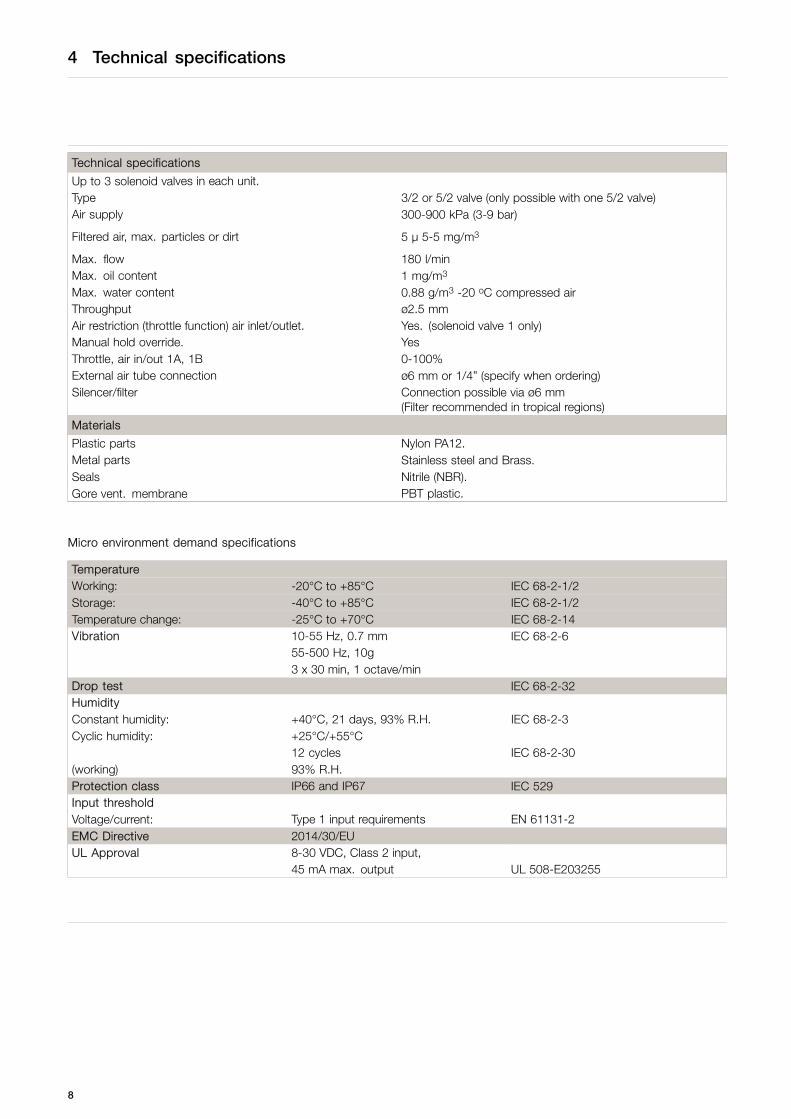
Technical specifications
Up to 3 solenoid valves in each unit.Type 3/2 or 5/2 valve (only possible with one 5/2 valve)Air supply 300-900 kPa (3-9 bar)
Filtered air, max. particles or dirt 5 µ 5-5 mg/m3
Max. flow 180 l/minMax. oil content 1 mg/m3
Max. water content 0.88 g/m3 -20 oC compressed airThroughput ø2.5 mmAir restriction (throttle function) air inlet/outlet. Yes. (solenoid valve 1 only)Manual hold override. YesThrottle, air in/out 1A, 1B 0-100%External air tube connection ø6 mm or 1/4” (specify when ordering)Silencer/filter Connection possible via ø6 mm
(Filter recommended in tropical regions)
Materials
Plastic parts Nylon PA12.Metal parts Stainless steel and Brass.Seals Nitrile (NBR).Gore vent. membrane PBT plastic.
Micro environment demand specifications
TemperatureWorking: -20°C to +85°C IEC 68-2-1/2Storage: -40°C to +85°C IEC 68-2-1/2Temperature change: -25°C to +70°C IEC 68-2-14Vibration 10-55 Hz, 0.7 mm IEC 68-2-6
55-500 Hz, 10g3 x 30 min, 1 octave/min
Drop test IEC 68-2-32HumidityConstant humidity: +40°C, 21 days, 93% R.H. IEC 68-2-3Cyclic humidity: +25°C/+55°C
12 cycles IEC 68-2-30(working) 93% R.H.Protection class IP66 and IP67 IEC 529Input thresholdVoltage/current: Type 1 input requirements EN 61131-2EMC Directive 2014/30/EUUL Approval 8-30 VDC, Class 2 input,
45 mA max. output UL 508-E203255
8

4 Technical specifications
4.2 ThinkTop Digital
Power SupplyThe ThinkTop is designed to be a part of the PLC’s Input/Output (I/O) system. It should be supplied from the same protectedpower supply as the other I/O devices. The I/O power supply should not be used for other kinds of load.
The unit is reverse polarity and short circuit protected.
Supply voltage nominal: . . . . . . . . . . . . . 24 ± 10% VDCSupply voltage absolute max.: . . . . . . 30 VDC.Supply voltage absolute min.: . . . . . . 8 VDC.Supply current*): . . . . . . . . . . . . . . . . . . . . Max. 45 mA (for sensor unit alone)
(excluding current to the solenoids, external sensor and the PLC input current).
*) The initial current during power-on is higher. The actual shape of the current pulse depends on the power supply used.Typical values are 150 mA RMS during 13 ms (regulated PS) to 360 mA RMS during 8 ms (unregulated PS).
Fulfillment of the UL requirements in UL508 requires the unit to be supplied by an isolating source that complies with therequirements for class 2 power units (UL1310) or class 2 and 3 transformers (UL1585).
Feedback signalsThe sensor system can be used for 4 feedback signals + 1 status signal = 5 digital PNP/NPN feedback signals.
Output signals from the sensor unit to the connected PLC.
Nominal voltage: . . . . . . . . . . . . . . . . . . . . Must match the selected type of ThinkTop.Load current: . . . . . . . . . . . . . . . . . . . . . . . . Typically 50 mA, max. 100 mA .Voltage drop: . . . . . . . . . . . . . . . . . . . . . . . . Typically 3 V at 50 mA.
PNP/NPN Polarity
PNP (sourcing) or NPN (sinking) function is selected with a jumper in term. 12 and 13. Jumper present = PNP. If changing toNPN, remove the jumber and make a power recycle. A power recycle is always required when changing this function.
Solenoid valve signalsThree output signals (with one common, terminal 11) from the terminal row are used for activation of the solenoids. Positive(connected with terminal 9) or negative.
Technical specificationsNorminal voltageNominal power
24 VDC1.0 W.
9

4 Technical specifications
4.3 ThinkTop, AS-Interface
Feedback signals
Power SupplyThe power supply to the complete unit is taken from the AS-Interface loop. The unit is reverse polarity protected.
Supply voltage: . . . . . . . . . . . . . . . . . . . . . . 29.5 - 31.6 VDC
Normal current consumption sensorboard . . . . . . . . . . . . . . . . . . . . . . . . . . . . . . . . 45 mA (excluding current for the solenoids and the external sensor).
Max. current consumption sensorboard . . . . . . . . . . . . . . . . . . . . . . . . . . . . . . . . 165 mA (if external devices e.g. solenoids and switches are connected to the sensor
board, a higher current consumption than 120 mA may occur, which this will damagethe sensor boards).
Feedback signals
Signals transmitted through the AS-Interface BUS to the AS-Interface master PLC.
The sensor system can be used for 3 feedback signals + 1 status signal = 4 feedback signals.
Slave profile options: (specify when ordering)
Slave profile v.2.1Default slave address: 0
IO code: 7 (4 bit bi-directional)IO code: F (slave without profile)ID1 code: FID2 code: FSlave profile = S-7.F.F.F
No. of slaves:AS-Interface specification 2.1 for max. 31 ThinkTop units on a single master/gateway
Slave profile v.3.0Default slave address: 0
IO code: 7 (4 bit bi-directional)IO code: AID1 code: 7ID2 code: 7Slave profile = S-7.A.7.7
No. of slaves:AS-Interface specification 3.0 for max. 62 ThinkTop units on a single master/gateway.
10

4 Technical specifications
AS-Interface bits assignment:For the AS-Interface version with 31 and 62 nodes, the following bit assignment will be used:
DI 0 . . . . . . . . . . . . . . . . . . . . . . . . . . . . . . . . . . De-Energised position (closed position)DI 1 . . . . . . . . . . . . . . . . . . . . . . . . . . . . . . . . . . Energised position (open position)DI 2 . . . . . . . . . . . . . . . . . . . . . . . . . . . . . . . . . . SeatLift 1 and 2 position (sum SeatLift signal)DI 3 . . . . . . . . . . . . . . . . . . . . . . . . . . . . . . . . . . Status
DO 0 . . . . . . . . . . . . . . . . . . . . . . . . . . . . . . . . . Not connectedDO 1 . . . . . . . . . . . . . . . . . . . . . . . . . . . . . . . . . Solenoid valve 1DO 2 . . . . . . . . . . . . . . . . . . . . . . . . . . . . . . . . . Solenoid valve 2DO 3 . . . . . . . . . . . . . . . . . . . . . . . . . . . . . . . . . Solenoid valve 3
Solenoid valve signals
Signals transmitted through the AS-Interface BUS to the AS-Interface master PLC.
Technical specificationsNominal voltage 24 VDCNominal power 1.0 W
11

4 Technical specifications
4.4 ThinkTop DeviceNet
DeviceNet features and functionality
Network size Up to 63 nodes
Network length Selectable end-to-end network distance varies with speed
Baud Rate125 Kbps250 Kbps500 Kbps
Distance500 m (1,640 ft)250 m (820 ft)100 m (328 ft)
Data packets 0-8 bytes
Bus topology Linear (trunk line/drop line); power and signal on the same network cable
Bus addressingPeer-to-peer with multi-cast (one-to-many); multi-master and master/slave special case; polledor change-of-state (exception-based)
System features Removal and replacement of devices from the network under power
The basic trunk-line/drop-line topology provides separate twisted-pair buses for both signal and power distribution. A thick or thin cable can beused for either trunk lines or drop lines. End-to-end network distance varies with data rate and cable size
Data rates 125 Kbps 250 Kbps 500 Kbps
Thick trunk length 500 m (1,640 ft) 250 m (820 ft) 100 m (328 ft)
Thick trunk length 100 m (328 ft) 100 m (328 ft) 100 m (328 ft)
Maximum drop length 6 m (20 ft) 6 m (20 ft) 6 m (20 ft)
Cumulative drop length 156 m (512 ft) 78 m (256 ft) 39 m (128 ft)
The end-to-end network distance varies with data rate and cable thickness.
DeviceNet requires a terminating resistor to be installed at each end of the trunk:
- 121 ohm- 1% metal film- 1/4 watt
Terminating resistors should not be installed at the end of a drop line, only at the two ends of the trunk-line.
For further information please refer to the DeviceNet Standard.
DeviceNet Features
Device type Generic Master/scanner N
Explicit peer-to-peer messaging N I/O Slave messaging
I/O peer-to-peer messaging N • Bit strobe N
Configuration consistency value N • Polling Y
Faulted node recovery N • Cyclic N
Baud rates 125K, 250K, 500K • Change of state (COS) N
Configuration method EDS
The end-to-end network distance varies with data rate and cable thickness.
12

4 Technical specifications
DeviceNet interfaceBaud rates: 125K, 250K and 500K.Polling I/O slave messaging.
Poll: 1 bytes.1 bytes = Input/outputs and alarms (class 4).
Node addressRange: 0-63.Default slave address: 63.
Power supplyThe power supply to the complete unit is taken from the DeviceNet.
Supply voltage: . . . . . . . . . . . . . . . . . . . . . 11-25 V DC, as specified for the DeviceNet.Supply current: . . . . . . . . . . . . . . . . . . . . . . Max. 45 mA (for sensor unit alone)
(excluding current to the solenoids and the external proximity switches).
ThinkTop DeviceNet features
Feedback signalsInput signals (produced by the sensor unit) transmitted over the DeviceNet - class 4.Five feedback signals: closed valve, open valve, seatlift 1, seatlift 2 and status.
The status signal is used for five purposes:
- To indicate that a setup is in progress (LED D).- To indicate an error condition (LED D), (flashing = software error), (steady = hardware error).- To indicate that maintenance is required (LED F).- To indicate whether there is a conflict in the self adjustment programme (LED F).- To indicate whether any communication exists between ThinkTop® and PLC (LED D, steady).
Solenoid signalsOutput signals received from the DeviceNet.Three bits to control the solenoid drives located in the sensor unit.
ThinkTop EDS fileThe EDS file can be downloaded from www.alfalaval.com by searching "ThinkTop" at the top of the main landing page. On theThinkTop landing page, choose Documentation in the menu and find the EDS package. Alternatively, both the EDS file andfurther information on DeviceNet can found at www.odva.org
13
4 Technical specifications
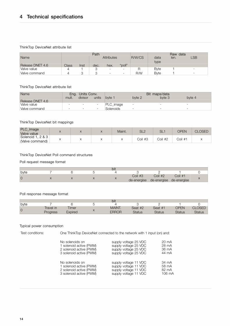
ThinkTop DeviceNet attribute list
Path Raw dataName Attributes R/W/CS data
typelen. LSB
Release DNET 4.6 Class Inst dec. hex. “poll”Valve valueValve command
44
13
33
--
--
RR/W
ByteByte
11
--
ThinkTop DeviceNet attribute list
Name Eng. Units Conv. Bit maps/datamult. divisor units byte 1 byte 2 byte 3 byte 4
Release DNET 4.6Valve valueValve command
--
--
--
PLC_imageSolenoids
--
--
--
ThinkTop DeviceNet bit mappings
PLC_ImageValve value
x x x Maint. SL2 SL1 OPEN CLOSED
Solenoid 1, 2 & 3(Valve command)
x x x x Coil #3 Coil #2 Coil #1 x
ThinkTop DeviceNet Poll command structures
Poll request message format
bitbyte 7 6 5 4 3 2 1 0
0 x x x xCoil #3
de-energiseCoil #2
de-energiseCoil #1
de-energisex
Poll response message format
bitbyte 7 6 5 4 3 2 1 0
0Travel inProgress
TimerExpired x
MAINT.ERROR
Seat #2Status
Seat #1Status
OPENStatus
CLOSEDStatus
Typical power consumption
Test conditions: One ThinkTop DeviceNet connected to the network with 1 input (on) and:
No solenoids on supply voltage 25 VDC 20 mA1 solenoid active (PWM) supply voltage 25 VDC 28 mA2 solenoid active (PWM) supply voltage 25 VDC 36 mA3 solenoid active (PWM) supply voltage 25 VDC 44 mA
No solenoids on supply voltage 11 VDC 34 mA1 solenoid active (PWM) supply voltage 11 VDC 58 mA2 solenoid active (PWM) supply voltage 11 VDC 82 mA3 solenoid active (PWM) supply voltage 11 VDC 106 mA
14

5 Installation
5.1 Installation on air actuators
Step 1
Always read the technical data carefully.
Always ensure the ThinkTop is electrically connected by authorised personnel.
Step 21. Fit the air fittings on the actuator if not mounted.2. Fit the activator stem (magnet) and tighten carefully
with a spanner.
2050-0015
Step 31. Place the ThinkTop on top of the actuator.2. Make sure X-ring is mounted.
2050-0016
Step 41. Ensure that the unit is correctly mounted by pressing down
on top of the ThinkTop.2. Cross tighten the two Allen screws carefully in the two opposite
directions.3. Turn the actuator so that the LEDs are at the front
2050-0017
15
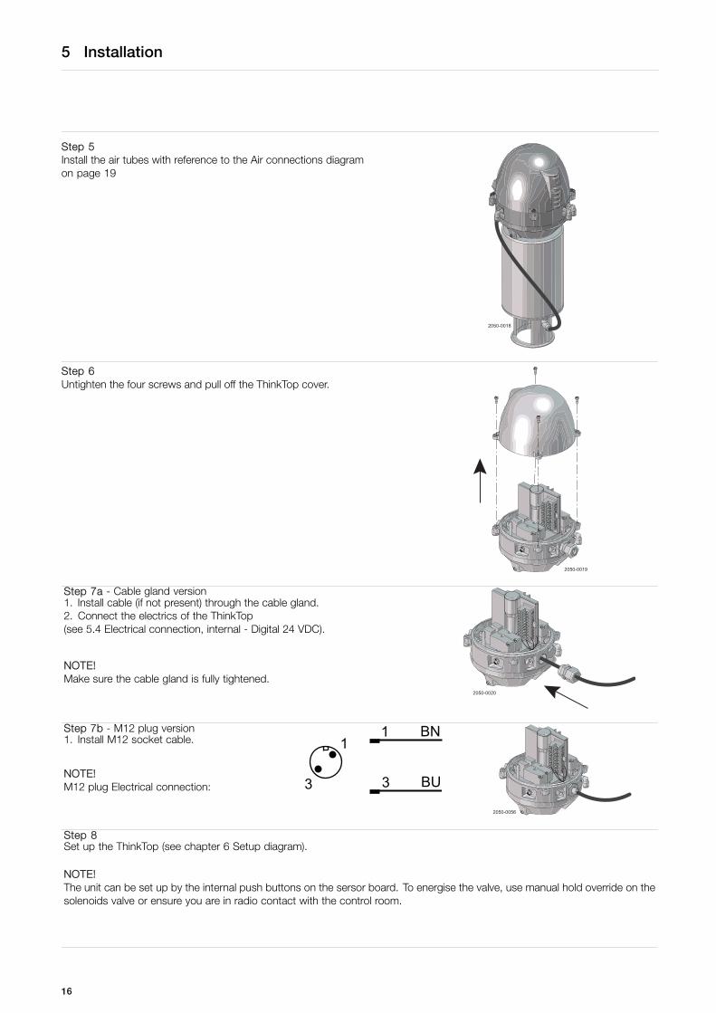
5 Installation
Step 5Install the air tubes with reference to the Air connections diagramon page 19
2050-0018
Step 6Untighten the four screws and pull off the ThinkTop cover.
2050-0019
Step 7a - Cable gland version1. Install cable (if not present) through the cable gland.2. Connect the electrics of the ThinkTop(see 5.4 Electrical connection, internal - Digital 24 VDC).
NOTE!Make sure the cable gland is fully tightened.
2050-0020
Step 7b - M12 plug version1. Install M12 socket cable.
NOTE!M12 plug Electrical connection:
11
33
BN
BU
2050-0056
Step 8Set up the ThinkTop (see chapter 6 Setup diagram).
NOTE!The unit can be set up by the internal push buttons on the sersor board. To energise the valve, use manual hold override on thesolenoids valve or ensure you are in radio contact with the control room.
16

5 Installation
5.2 Installation on Series 700 valves
Step 11. Remove the cover by loosening the four cover screws.2. Separate the adapter from the base by loosening the three
recess screws on top of the base.
Installation on air actuators:
2050-0023
Step 21. Fit air fittings on actuator.2. Position packing retainer in recess on actuator top.3. Fit counter nut and indication pin (magnet) on actuator rod.
Engage approx. ¼ thread. Tighten counter nut and indicatorwith two wrenches.
2050-0049
Step 31. Place the two O-rings in the grooves in the bottom of the
adapter. Then place the adapter on the actuator top. The smallO-ring must be positioned over the air hole on the actuator.
2. Fasten the adapter with the four 5/16” Allen screws.
2050-0035
17
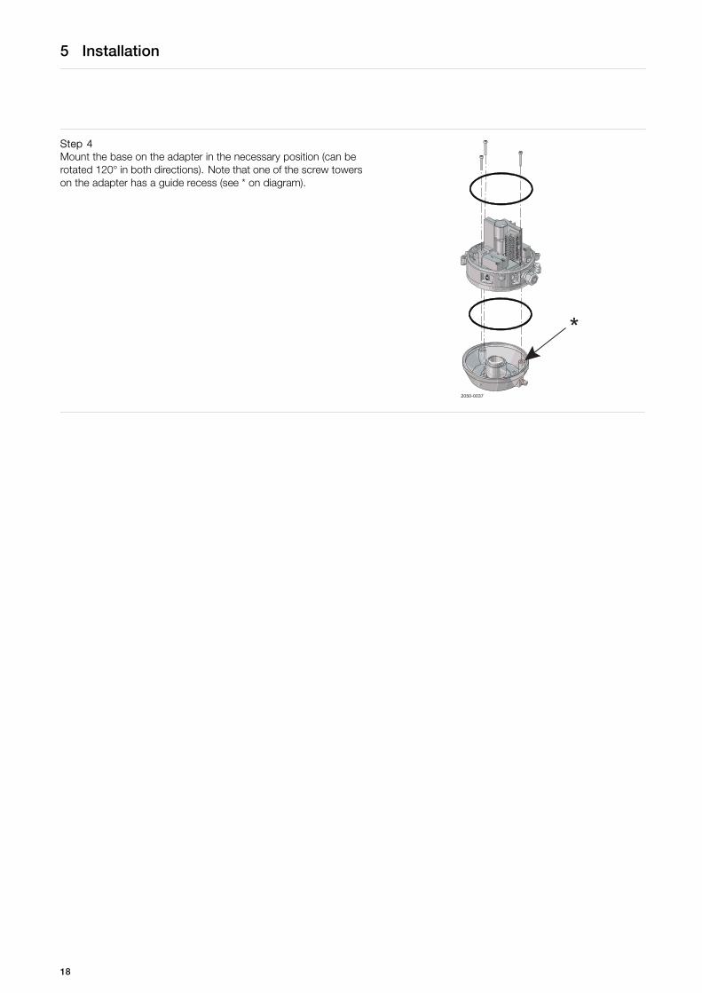
5 Installation
Step 4Mount the base on the adapter in the necessary position (can berotated 120° in both directions). Note that one of the screw towerson the adapter has a guide recess (see * on diagram).
2050-0037
*
18
5 Installation
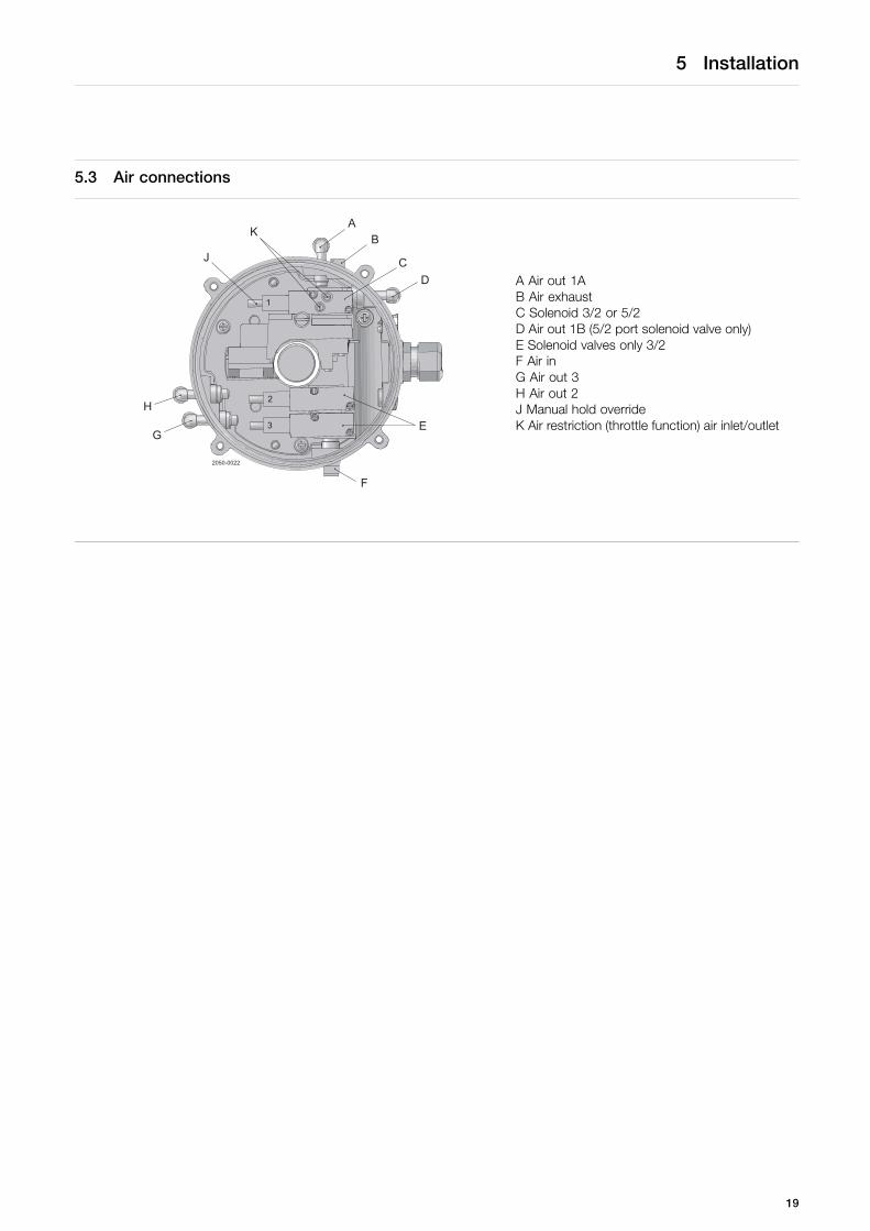
5.3 Air connections
A
F
E
DC
BK
J
H
G
2050-0022
3
2
1
A Air out 1AB Air exhaustC Solenoid 3/2 or 5/2D Air out 1B (5/2 port solenoid valve only)E Solenoid valves only 3/2F Air inG Air out 3H Air out 2J Manual hold overrideK Air restriction (throttle function) air inlet/outlet
19
5 Installation
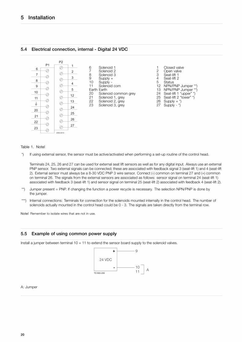
5.4 Electrical connection, internal - Digital 24 VDC
6 Solenoid 1 1 Closed valve7 Solenoid 2 2 Open valve8 Solenoid 3 3 Seat-lift 19 Supply + 4 Seat-lift 210 Supply - 5 Status11 Solenoid com 12 NPN/PNP Jumper **)Earth Earth 13 NPN/PNP Jumper **)20 Solenoid common grey 24 Seat-lift 1 “upper” *)21 Solenoid 1, grey 25 Seat-lift 2 “lower” *)22 Solenoid 2, grey 26 Supply + *)
6
23
22
21
20
11
10
9
8
7
1
27
26
25
24
12
5
4
3
2
13
P2P1
2050-0013
23 Solenoid 3, grey 27 Supply - *)
Table 1. Note!
*) If using external sensor, the sensor must be active/activated when performing a set-up routine of the control head.
Terminals 24, 25, 26 and 27 can be used for external seat lift sensors as well as for any digital input. Always use an externalPNP sensor. Two external signals can be connected; these are associated with feedback signal 3 (seat-lift 1) and 4 (seat-lift2). External sensor must always be a 8-30 VDC PNP 3 wire sensor. Connect (-) common on terminal 27 and (+) commonon terminal 26. The signals from the external sensors are associated as follows: sensor signal on terminal 24 (seat-lift 1)associated with feedback 3 (seat-lift 1) and sensor signal on terminal 25 (seat-lift 2) associated with feedback 4 (seat-lift 2).
**) Jumper present = PNP. If changing the function a power recycle is necessary. The selection NPN/PNP is done bythe jumper.
***) Internal connections: Terminals for connection for the solenoids mounted internally in the control head. The number ofsolenoids actually mounted in the control head could be 0 - 3. The signals are taken directly from the terminal row.
Note! Remember to isolate wires that are not in use.
5.5 Example of using common power supply
Install a jumper between terminal 10 + 11 to extend the sensor board supply to the solenoid valves.
TD 800-206
A: Jumper
20

5 Installation
5.6 Electrical connection, internal - AS-Interface
6 ASI + (BN, brown) 1 N/C7 ASI - (BU, blue) 2 N/C8 N/C 3 N/C9 N/C 4 N/C10 N/C 5 N/C11 N/C 12 PWM Jumper **)Earth Earth 13 PWM Jumper **)20 Solenoid common grey 24 Seat-lift 1 “upper” *)21 Solenoid 1, grey 25 Seat-lift 2 “lower” *)22 Solenoid 2, grey 26 Supply + *)
6
23
22
21
20
11
10
9
8
7
1
27
26
25
24
12
5
4
3
2
13
P2P1
2050-0013
23 Solenoid 3, grey 27 Supply - *)
Table 2. Note!
*) If using external sensor, the sensor must be active/activated when performing a set-up routine of the control head.
Terminals 24, 25, 26 and 27 can be used for external seat lift sensors as well as for any digital input. Always use an externalPNP sensor. Two external signals can be connected; these are associated with feedback signal 3 (seat lift 1) and 4 (seat lift2). External sensor must always be a 8-30 VDC PNP 3 wire sensor. Connect (-) common on terminal 27 and (+) commonon terminal 26. The signals from the external sensors are associated as follows: sensor signal on terminal 24 (seat lift 1)associated with feedback 3 (seat lift 1) and sensor signal on terminal 25 (seat lift 2) associated with feedback 4 (seat lift 2).
**) Jumper present = PWM. Reducing power consumption of solenoid valves.
***) Internal connections: Terminals for connection for the solenoids mounted internally in the control head. The number ofsolenoids actually mounted in the control head could be 0 - 3. The signals are taken directly from the terminal row.
Note! Remember to isolate wires that are not in use.
21
5 Installation
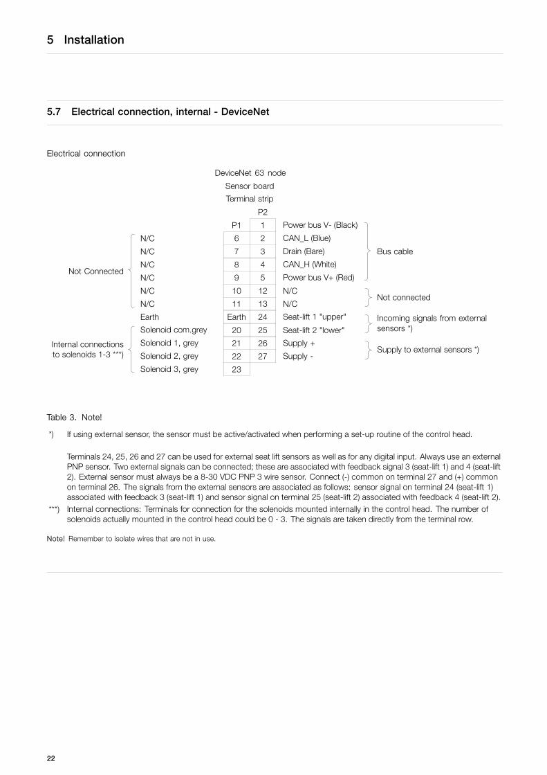
5.7 Electrical connection, internal - DeviceNet
Electrical connection
DeviceNet 63 node
Sensor board
Terminal strip
P2
P1 1 Power bus V- (Black)
N/C 6 2 CAN_L (Blue)
N/C 7 3 Drain (Bare)
N/C 8 4 CAN_H (White)
N/C 9 5 Power bus V+ (Red)
Bus cable
N/C 10 12 N/C
Not Connected
N/C 11 13 N/CNot connected
Earth Earth 24 Seat-lift 1 "upper"
Solenoid com.grey 20 25 Seat-lift 2 "lower"Incoming signals from externalsensors *)
Solenoid 1, grey 21 26 Supply +
Solenoid 2, grey 22 27 Supply -Supply to external sensors *)
Internal connectionsto solenoids 1-3 ***)
Solenoid 3, grey 23
Table 3. Note!
*) If using external sensor, the sensor must be active/activated when performing a set-up routine of the control head.
Terminals 24, 25, 26 and 27 can be used for external seat lift sensors as well as for any digital input. Always use an externalPNP sensor. Two external signals can be connected; these are associated with feedback signal 3 (seat-lift 1) and 4 (seat-lift2). External sensor must always be a 8-30 VDC PNP 3 wire sensor. Connect (-) common on terminal 27 and (+) commonon terminal 26. The signals from the external sensors are associated as follows: sensor signal on terminal 24 (seat-lift 1)associated with feedback 3 (seat-lift 1) and sensor signal on terminal 25 (seat-lift 2) associated with feedback 4 (seat-lift 2).
***) Internal connections: Terminals for connection for the solenoids mounted internally in the control head. The number ofsolenoids actually mounted in the control head could be 0 - 3. The signals are taken directly from the terminal row.
Note! Remember to isolate wires that are not in use.
22
6 Setup diagram
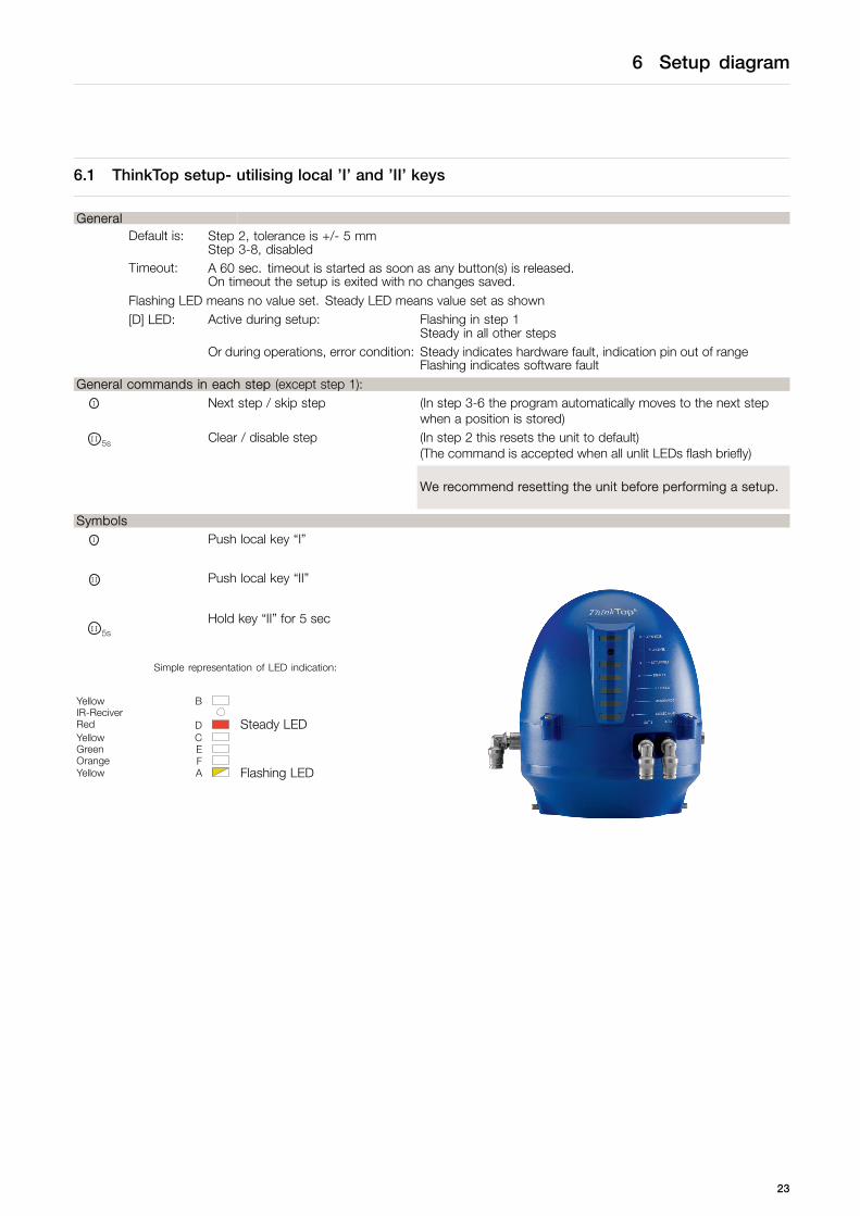
6.1 ThinkTop setup- utilising local ’I’ and ’II’ keys
GeneralDefault is: Step 2, tolerance is +/- 5 mm
Step 3-8, disabledTimeout: A 60 sec. timeout is started as soon as any button(s) is released.
On timeout the setup is exited with no changes saved.Flashing LED means no value set. Steady LED means value set as shown[D] LED: Active during setup: Flashing in step 1
Steady in all other stepsOr during operations, error condition: Steady indicates hardware fault, indication pin out of range
Flashing indicates software faultGeneral commands in each step (except step 1):
5s Next step / skip step (In step 3-6 the program automatically moves to the next stepwhen a position is stored)
5s Clear / disable step (In step 2 this resets the unit to default)(The command is accepted when all unlit LEDs flash briefly)
We recommend resetting the unit before performing a setup.
Symbols
5s Push local key “I”
5s Push local key “II”
5s
Hold key “II” for 5 sec
Simple representation of LED indication:
Yellow BIR-ReciverRed D Steady LEDYellow CGreen EOrange FYellow A Flashing LED
23

6 Setup diagram
Enter SetupStep 1 -
Step 2 - Setup valve type
Step 3 - Set closed position
Step 4 - Set open position
Step 5 - Set upper seat lift
Step 6 - Set lower seat lift
Step 7 - Set self adjust (Recommended: Disabled )
Step 8 - Setup maintenance
Nextstep
Nextstep
Nextstep
Nextstep
Nextstep
Nextstep
Nextstep
Nextstep
B
DCEFA
B
DCEFA
B
DCEFA
B
DCEF
B
DCEFA
B
DCEFA
B
DCEFA
B
DCEFA
Save and Exit
Default +/- 5mm
Default Position stored
Default Position stored
Default Position stored
Default
DefaultDisabled
DefaultDisabled
Position stored
No 1
Associatedwithclosed/openposition
90 days 180 days 270 days 360 days
Associatedwithclosedposition
Associatedwithopenposition
No 2
5s
No 4No 3
Exit no change accepted
Activate the valve to the close position
(De-energized)Auto
Activate the valve to the open position
(Energized) Auto
Activate the valve to upper seat lift. When
using an external sensor the sensor must
be active when “1” is pushed Auto
Auto
Activate the valve to lower seat lift.
When using an external sensor the
sensor must be active when “1” is pushed
I
II
II
II
II
II
II II
II
II
II
II
4II
II II II
II II II 4II 4II
+90 days (Up tomax 18 years)
Next step
I
Next step
Next step
I
I
I
I
I
I
I
I
I
I
24

6 Setup diagram
Tolerance programs
Default No. 1 No. 2 No. 3 No. 4
(Used for selfadjustment)
MH Koltek ARC LKB Unique Mixproof Unique SSV
SMP-EC SRC (LKLA-T) SMP-SC Spillage free Unique Mixproof PMO
Unique SSV NO Series 700 SRC-PV Unique Mixproof Curd
shut off AMP Unique Mixproof CP3
Unique Mixproof LP
Unique Mixproof HT
Unique Mixproof VT
Unique Mixproof 3A
Unique 7000
ARC
SRC
SBV
Series 700
25

6 Setup diagram
6.2 ThinkTop setup- utilising IR keypad
General
Flashing LED means no value set. Steady LED means value set as shown.Default: Step 2, factory-set tolerance band +/- 5 mm
Step 3-8, disabledD LED: Active during setup: Flashing in step 1
Steady in all other stepsOr during operations, error condition: Steady indicates hardware fault, indication pin out of range
Flashing indicates software faultTimeout: A 60 sec. timeout is started as soon as any button/s is released
On timeout the setup is exited with no changes savedIR Keypad: Remote distance 0-300 mm to ThinkTop®
Symbols
X Push key on IR keypad with the same number
Simple representation of LED indication:
Yellow BIR-ReciverRed D Steady LEDYellow CGreen EOrange FYellow A Flashing LED
General commands in each step (except step 1):
0 Next step / skip step (In step 3-6 the program automatically moves to the next stepwhen a position is stored)
5 Clear / disable step (In step 2 this resets the unit and sets the step 2-8 to default)(The command is accepted when all unit LEDs flash briefly)
We recommend resetting the unit before performing a setup.Always check for correct signals after the setup.
26

6 Setup diagram
Enter SetupStep 1 -
Step 2 - Setup valve type
Step 3 - Set closed position
Step 4 - Set open position
Step 5 - Set upper seat lift
Step 6 - Set lower seat lift
Step 7 - Set self adjust (Recommended: Disabled )
Step 8 - Setup maintenance
Nextstep
Nextstep
Nextstep
Nextstep
Nextstep
Nextstep
Nextstep
Nextstep
0
1
2
1 2 3
1 2
1
1
1
4 5
0
0
0
0
0
0
0
0
B
DCEFA
B
DCEFA
B
DCEFA
B
DCEF
B
DCEFA
B
DCEFA
B
DCEFA
B
DCEFA
Save and Exit
Default +/- 5mm
Default Position stored
Default Position stored
Default Position stored
Default
DefaultDisabled
DefaultDisabled
Position stored
No 1
Associatedwithclosed/openposition
90 days 180 days 270 days 360 days
Associatedwithclosedposition
Associatedwithopenposition
No 2 No 4
Reset unit
5
Cleatposition
5
Clear position
5
Clear position
5
Clear position
5
Disablefunction
5
Disable function
No 3
Exit no change accepted
Activate the valve to the close position
(De-energized) Auto
Activate the valve to the open position
(Energized) Auto
Activate the valve to upper seat lift. When
using an external sensor the sensor must be
active when “1” is pushed Auto
Auto
Activate the valve to lower seat lift.
When using an external sensor the sensor
must be active when “1” is pushed
3
1 2 3 4
27

6 Setup diagram
6.3 ThinkTop quick setup guide
Valve: Unique SSV, SRC/ARC type NC (self-adjustment disabled)Push: I - and wait until red LED flashesPush: IHold: II 5s - hold for 5 sec (clear all stored parameters)Push: II (red + yellow LED)Push: II (red + yellow + green LED)Push: II (red + yellow + green + orange LED)Push: II (red + yellow + green + orange + yellow LED)Push: IPush: II - to approve valve down (closed)
Activate Valve opensPush: II - to approve (open)
Deactivate Valve returns to closedPush: I (no upper seat-lift)Push: I (no lower seat-lift)Push: I (no self-adjustment)Push: I (no maintenance)Push: II Red LED flashes (save & exit by push)
Setup complete
Valve: SRC/ARC type NO (self-adjustment enabled)Push: I - and wait until red LED flashesPush: IHold: II 5s - hold for 5 sec (clear all stored parameters)Push: II (red + yellow LED)Push: I
Activate Valve closesPush: II - to approve valve closed
Deactivate Valve opensPush: II - to approve valve is openPush: I (no upper seat-lift)Push: I (no lower seat-lift)Push: II = self-adjustmentPush: IPush: I (no maintenance)Push: II Red LED flashes (save & exit by push)
Setup complete
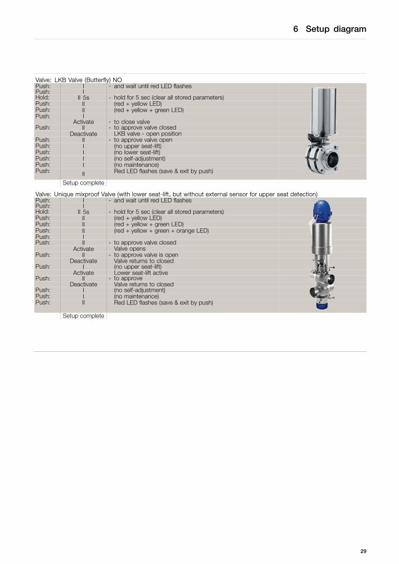
Valve: LKB Valve (Butterfly) NCPush: I - and wait until red LED flashesPush: IHold: II 5s - hold for 5 secPush: II (red + yellow LED)Push: II (red + yellow + green LED)Push: IPush: II - to approve valve closed (indication- stem up)
Activate LKB valve - open position (indication- stem down)Push: II - to approve valve is open
Deactivate Valve returns to closedPush: I (no upper seat-lift)Push: I (no lower seat-lift)Push: I (no self-adjustment)Push: I (no maintenance)Push: II Red LED flashes (save & exit by push)
Setup complete
28
6 Setup diagram
Valve: LKB Valve (Butterfly) NOPush: I - and wait until red LED flashesPush: IHold: II 5s - hold for 5 sec (clear all stored parameters)Push: II (red + yellow LED)Push: II (red + yellow + green LED)Push: I
Activate - to close valvePush: II - to approve valve closed
Deactivate LKB valve - open positionPush: II - to approve valve openPush: I (no upper seat-lift)Push: I (no lower seat-lift)Push: I (no self-adjustment)Push: I (no maintenance)Push: II Red LED flashes (save & exit by push)
Setup complete
Valve: Unique mixproof Valve (with lower seat-lift, but without external sensor for upper seat detection)Push: I - and wait until red LED flashesPush: IHold: II 5s - hold for 5 sec (clear all stored parameters)Push: II (red + yellow LED)Push: II (red + yellow + green LED)Push: II (red + yellow + green + orange LED)Push: IPush: II - to approve valve closed
Activate Valve opensPush: II - to approve valve is open
Deactivate Valve returns to closedPush: I (no upper seat-lift)
Activate Lower seat-lift activePush: II - to approve
Deactivate Valve returns to closedPush: I (no self-adjustment)Push: I (no maintenance)Push: II Red LED flashes (save & exit by push)
Setup complete
29
7 Fault finding
7.1 Fault finding and LEDs
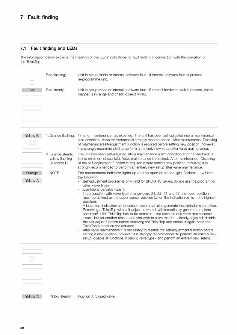
The information below explains the meaning of the LEDs’ indications for fault finding in connection with the operation ofthe ThinkTop.
Red flashing: Unit in setup mode or internal software fault. If internal software fault is present,re-programme unit.
Red Red steady: Unit in setup mode or internal hardware fault. If internal hardware fault is present, checkmagnet is in range and check correct wiring.
Yellow B 1. Orange flashing: Time for maintenance has experied. The unit has been self-adjusted into a maintenancealert condition. Valve maintenance is strongly recommended. After maintenance: Disablingof maintenance/self-adjustment function is required before setting new position, however,it is strongly recommended to perform an entirely new setup after valve maintenance.
2. Orange steady,yellow flashing(A and/or B):
The unit has been self-adjusted into a maintenance alarm condition and the feedback islost (a minimum of seal left). Valve maintenance is required. After maintenance: Disablingof the self-adjustment function is required before setting new position, however, it isstrongly recommended to perform an entirely new setup after valve maintenance.
Orange NOTE!
Yellow A
The maintenance indicator lights up and an open or closed light flashes..... = Notethe following:- Self-adjustment program is only valid for SRC/ARC valves; do not use the program for
other valve types.- Use tolerance/valve type 1.- In conjunction with valve type change-over; 21, 22, 31 and 32, the open position
must be defined as the upper sensor position (when the indication pin is in the highestposition).
- A loose top, indication pin or sensor system can also generate the alert/alarm condition.- Removing a ThinkTop with self-adjust activated, will immediately generate an alarm
condition! If the ThinkTop has to be removed - not because of a valve maintenanceissue - but for another reason and you wish to store the data already adjusted, disablethe self-adjust function before removing the ThinkTop and enable it again once theThinkTop is back on the actuator.
- After valve maintenance it is necessary to disable the self-adjustment function beforesetting a new position, however, it is strongly recommended to perform an entirely newsetup (disable all functions in step 2 valve type - and perfom an entirely new setup).
Yellow A Yellow steady: Position A (closed valve).
30
7 Fault finding
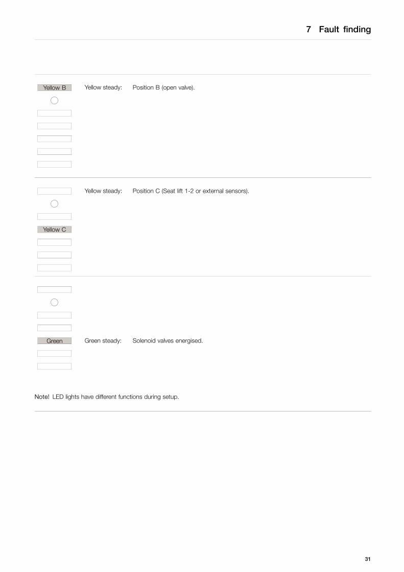
Yellow B Yellow steady: Position B (open valve).
Yellow steady: Position C (Seat lift 1-2 or external sensors).
Yellow C
Green Green steady: Solenoid valves energised.
Note! LED lights have different functions during setup.
31
8 Maintenance
Read the instructions carefully.Handle scrap correctly.Always have spare X-rings to hand.
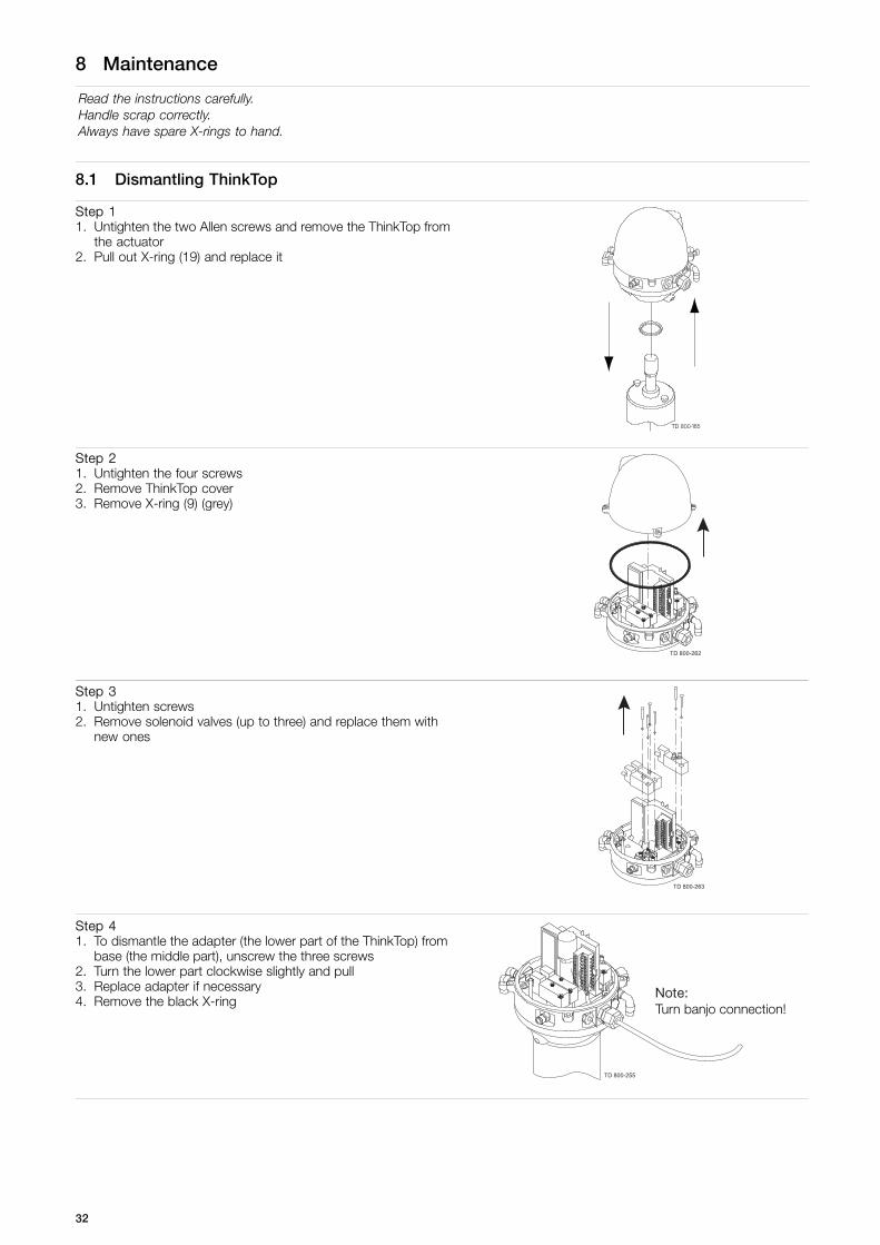
8.1 Dismantling ThinkTop
Step 11. Untighten the two Allen screws and remove the ThinkTop from
the actuator2. Pull out X-ring (19) and replace it
85
Step 21. Untighten the four screws2. Remove ThinkTop cover3. Remove X-ring (9) (grey)
TD 800-262
Step 31. Untighten screws2. Remove solenoid valves (up to three) and replace them with
new ones
TD 800-263
Step 41. To dismantle the adapter (the lower part of the ThinkTop) from
base (the middle part), unscrew the three screws2. Turn the lower part clockwise slightly and pull3. Replace adapter if necessary4. Remove the black X-ring
TD 800-255
Note:Turn banjo connection!
32
8 Maintenance
Read the instructions carefully.Handle scrap correctly.Always have spare X-rings to hand.
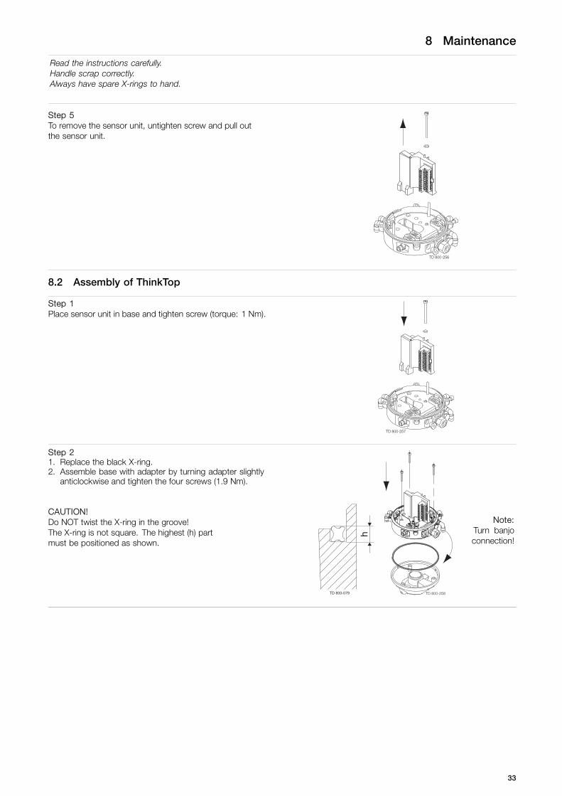
Step 5To remove the sensor unit, untighten screw and pull outthe sensor unit.
TD 800-256
8.2 Assembly of ThinkTop
Step 1Place sensor unit in base and tighten screw (torque: 1 Nm).
TD 800-257
Step 21. Replace the black X-ring.2. Assemble base with adapter by turning adapter slightly
anticlockwise and tighten the four screws (1.9 Nm).
CAUTION!Do NOT twist the X-ring in the groove!The X-ring is not square. The highest (h) partmust be positioned as shown.
h
TD 800-079 TD 800-258
Note:Turn banjoconnection!
33
8 Maintenance
Read the instructions carefully.Handle scrap correctly.Always have spare X-rings to hand.
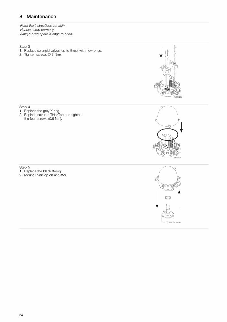
Step 31. Replace solenoid valves (up to three) with new ones.2. Tighten screws (0.2 Nm).
TD 800-264
Step 41. Replace the grey X-ring.2. Replace cover of ThinkTop and tighten
the four screws (0.6 Nm).
TD 800-265
Step 51. Replace the black X-ring.2. Mount ThinkTop on actuator.
85
34

8 Maintenance
Read the instructions carefully.Handle scrap correctly.Always have spare X-rings to hand.
8.3 Dismantling and assembling Series 700 valves
Step 11. Remove the cover by loosening the four cover screws.2. Separate the adapter from the base by loosening the three
recess screws on top of the base.
TD 800-257
Step 21. Fit air fittings on actuator.2. Position packing retainer in recess on actuator top.3. Fit counter nut and indicator (magnet) on actuator rod. Engage
approx. ¼” thread. Tighten counter nut and indicator with twowrenches.
Step 31. Place the two O-rings in the grooves in the bottom of the
adapter. Then place the adapter on the actuator top. The smallO-ring must be positioned over the air hole on the actuator.
2. Fasten the adapter with the four 5/16” Allen screws.
35
8 Maintenance
Read the instructions carefully.Handle scrap correctly.Always have spare X-rings to hand.
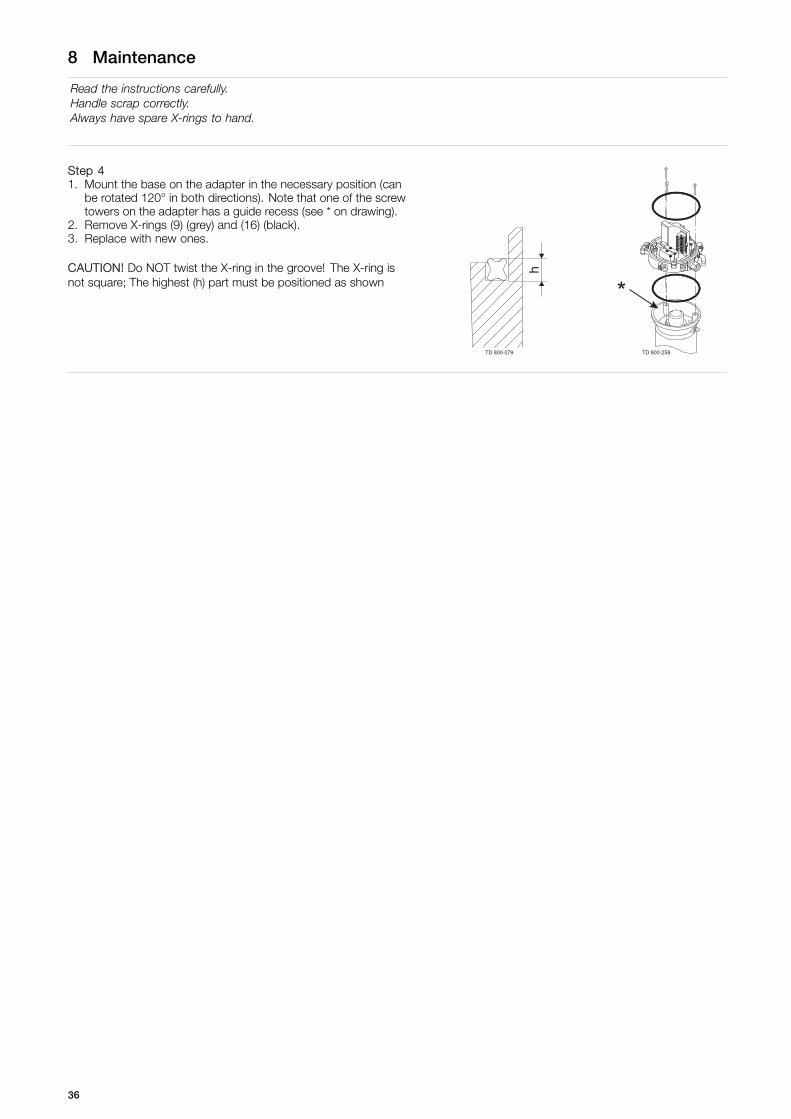
Step 41. Mount the base on the adapter in the necessary position (can
be rotated 120° in both directions). Note that one of the screwtowers on the adapter has a guide recess (see * on drawing).
2. Remove X-rings (9) (grey) and (16) (black).3. Replace with new ones.
CAUTION! Do NOT twist the X-ring in the groove! The X-ring isnot square; The highest (h) part must be positioned as shown
h
TD 800-079 TD 800-258
*
36

9 Parts list
The items refer to the parts lists in the following sections
9.1 Diagrams for ThinkTop
2053-0000
300
mm
(12”
)
ø137 mm (5½”)
225 mm (9”)
172
mm
(7”)
TD 800-267
1
20
5
1718
19
15
16
8
9
6a
6b
TD 800-262
1
3
2
37
9 Parts list
The items refer to the parts lists in the following sections
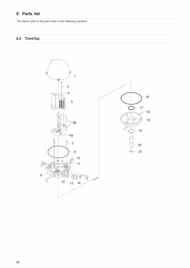
9.2 ThinkTop
1
4
6a
6b
5
3
14
11
10
9
7
1312
8
27
20
19
15
1817
16
TD 800-268
38
9 Parts list
The items refer to the parts lists in the following sections
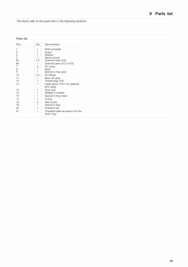
Parts list
Pos. Qty Denomination
1 1 Shell complete3 1 Screw4 1 Washer5 1 Sensor board6a 1-2 Solenoid valve (3/2)6b 1 Solenoid valve (3/2 or 5/2)7 3 PT screw8 1 Base9 1 Special X-ring, grey10 2-5 Air fittings11 1 Blow-off valve12 1 Thread plug, PG713 1 Cable gland, PG11 (or optional
M12 plug)14 1 Gore vent15 1 Adapter complete16 1 Special X-ring, black17 1 O-ring18 2 Allen screw19 1 Special X-ring20 1 Indication pin27 1 Threaded plate (accessory for the
Think Top)
39

.
40

9 Parts list
The items refer to the parts lists in the following sections
9.3 Diagrams for ThinkTop: Series 700
2053-0000
300
mm
(12”
)
ø137 mm (5½”)
225 mm (9”)
172
mm
(7”)
TD 800-269
6a
TD 800-271
1
3
212
1011
6b
14
13
7
34
41
9 Parts list
The items refer to the parts lists in the following sections
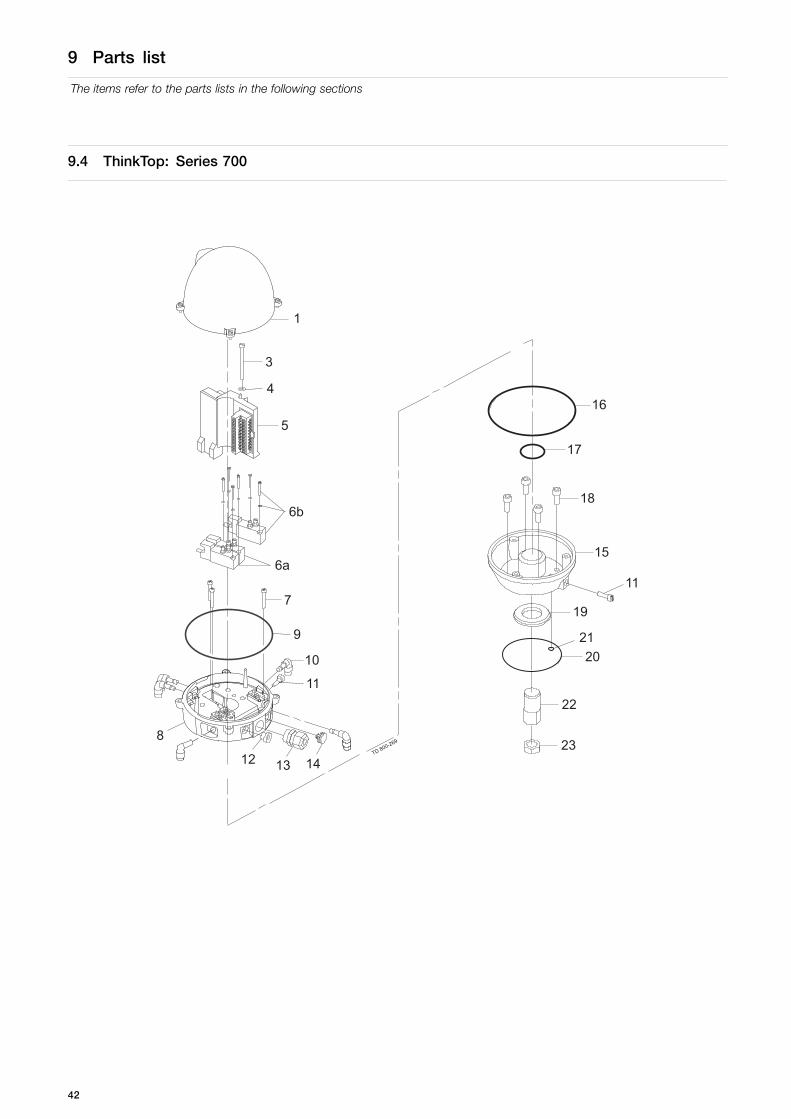
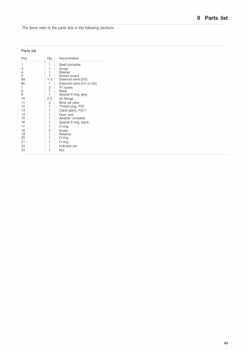
9.4 ThinkTop: Series 700
1
4
6a
6b
5
3
14
11
10
9
7
1312
8
21
11
18
15
17
16
TD 800-269
20
23
22
19
42
9 Parts list
The items refer to the parts lists in the following sections
Parts list
Pos. Qty Denomination
1 1 Shell complete3 1 Screw4 1 Washer5 1 Sensor board6a 1-2 Solenoid valve (3/2)6b 1 Solenoid valve (3/2 or 5(2)7 3 PT screw8 1 Base9 1 Speciel X-ring, grey10 2-5 Air fittings11 2 Blow-off valve12 1 Thread plug, PG713 1 Cable gland, PG1114 1 Gore vent15 1 Apapter complete16 1 Special X-ring, black17 1 O-ring18 4 Screw19 1 Retainer20 1 O-ring21 1 O-ring22 1 Indicator pin23 1 Nut
43

How to contact Alfa LavalContact details for all countries arecontinually updated on our website.Please visit www.alfalaval.com to access the information directly.
© Alfa Laval Corporate ABThis document and its contents is owned by Alfa Laval Corporate AB and protected by laws governing intellectual property and thereto related rights. It is the responsibility of the user of thisdocument to comply with all applicable intellectual property laws. Without limiting any rights related to this document, no part of this document may be copied, reproduced or transmitted in anyform or by any means (electronic, mechanical, photocopying, recording, or otherwise), or for any purpose, without the expressed permission of Alfa Laval Corporate AB. Alfa Laval Corporate ABwill enforce its rights related to this document to the fullest extent of the law, including the seeking of criminal prosecution.