instruction manual bedienungsanleitung rtf manuel d ... · en 4 • always keep a safe distance in...
TRANSCRIPT

Instruction ManualBedienungsanleitungManuel d’utilisationManuale di Istruzioni
RTF

2EN
WARNING: Read the ENTIRE instruction manual to become familiar with the features of the product before operating. Failure to operate the product correctly can result in damage to
the product, personal property and cause serious injury. This is a sophisticated hobby product. It must be operated with cau-tion and common sense and requires some basic mechanical ability.
The following terms are used throughout the product literature to indi-cate various levels of potential harm when operating this product:WARNING: Procedures, which if not properly followed, create the probability of property damage, collateral damage, and serious injury OR create a high probability of superficial injury.CAUTION: Procedures, which if not properly followed, create the prob-ability of physical property damage AND a possibility of serious injury.NOTICE: Procedures, which if not properly followed, create a possibility of physical property damage AND a little or no possibility of injury.
NOTICEAll instructions, warranties and other collateral documents are subject to change at the sole discretion of Horizon Hobby, LLC. For up-to-date product literature, visit www.horizonhobby.com and click on the support tab for this product.
Meaning of Special Language
3 EN
Age Recommendation: Not for children under 14 years. This is not a toy.
Failure to operate this Product in a safe and responsible manner could result in injury or damage to the product or other property. This product is not intended for use by children without direct adult supervision. Do not use with incompatible components or alter this product in any way outside of the instructions provided by Horizon Hobby, LLC. This manual contains instructions for safety, operation and maintenance. It is essential to read and follow all the instruc-tions and warnings in the manual, prior to assembly, setup or use, in order to operate correctly and avoid damage or serious injury.

4EN
•Always keep a safe distance in all directions around your model to avoid collisions or injury. This model is controlled by a radio signal subject to interference from many sources outside your control. Interference can cause momentary loss of control.
•Always operate your model in open spaces away from full-size vehicles, traffic and people.
•Always carefully follow the directions and warnings for this and any op-tional support equipment (chargers, rechargeable battery packs, etc.).
•Always keep all chemicals, small parts and anything electrical out of the reach of children.
•Always avoid water exposure to all equipment not specifically designed and protected for this purpose. Moisture causes damage to electronics.
•Never place any portion of the model in your mouth as it could cause serious injury or even death.
•Never operate your model with low transmitter batteries.•Always keep aircraft in sight and under control.•Always move the throttle fully down at rotor strike.•Always use fully charged batteries.•Always keep transmitter powered on while aircraft is powered.•Always remove batteries before disassembly.•Always keep moving parts clean.•Always keep parts dry.•Always let parts cool after use before touching.
Safety Precautions and Warnings

5 EN
If you are operating this product in North America, you are required to have an Amateur Radio (HAM) license. Visit www.arrl.org for more information.
•Always remove batteries after use.•Never operate aircraft with damaged wiring.•Never touch moving parts.
This product uses Betaflight Third Party Software in portions of its coding. For more information on Betaflight Software, please visit: https://github.com/betaflight/betaflight/wiki.
THIRD PARTY SOFTWARE. This product may include code developed by one or more third parties (“Third Party Software”). Some Third Party Software may be subject to other terms and conditions that may be available for download with the product documentation. Notwithstanding the terms and conditions of this Agreement, the Third Party Software is licensed to you subject to the terms and conditions of the software license agreement identified in the open source software disclosure. If the third party terms and conditions include licenses that provide for the availability of source code (such as the GNU General Public License), the open source software disclosure or the media on which the software may be delivered will provide instructions where a copy of such source code can be obtained.

6EN
Table of ContentsFirst Flight Preparation ............10Flying Checklist .......................10Charging Warnings ..................11Charge the Flight Battery .........11Installing the Propellers ...........13Installing the Transmitter Batteries (RTF) .......14Install the Flight Battery ...........15BNF Transmitter Setup .............16Transmitter and Receiver Binding ..............16Transmitter Control (RTF) .........18Understanding the Primary Flight Controls ............20Flight Mode Selection ..............22Fly the Quadcopter ..................23Low Voltage Cutoff (LVC) ..........25
Battery Level Indicator .............25Changing the Center LED Taillight Color ........26FPV Camera and Video Transmitter ..............27Video Monitor (RTF) .................29Troubleshooting Guide .............34Exploded View.........................36Parts Listings ..........................37Optional Parts .........................37Limited Warranty .....................38Warranty and Service Contact Information .................42FCC Information ......................43IC Information .........................44Compliance Information for the European Union ............45

7 EN
Length 3.74 in (95mm)Width 3.74 in (95mm)Height 1.77 in (45mm)Propeller Diameter 1.57 in (40mm)Flying Weight 1.83 oz (52g)
Specifications
To receive product updates, special offers and more, register your product at www.bladehelis.com.
NOTICE: Consult local laws and ordinances before operating FPV (first person view) equipment. In some areas, FPV operation may be limited or prohibited. You are responsible for operating this product in a legal and responsible manner.

8EN
Box Contents:•Inductrix® FPV Plus Quadcopter•3.7V 500mAh 1S 25C LiPo (EFLB5001S25UM)•Charger, 1S 3.7V LiPo, USB (EFLC1013)•Video Monitor w/DVR (SPMVM435) (RTF Only)•MLP6DSM 6CH Transmitter 2.4GHz (EFLRMLP6) (RTF Only)

9 EN
First Flight Preparation
•Remove and inspect contents•Begin charging the flight battery•Assemble the aircraft•Program your computer transmitter•Install the flight battery in the aircraft (once it has been fully charged)•Bind your transmitter•Familiarize yourself with the controls•Find a suitable area for flying
Flying Checklist
❏Always turn the transmitter on first ❏Plug the flight battery into the lead from the ESC ❏Allow the ESC to initialize and arm properly ❏Fly the model ❏Land the model ❏Unplug the flight battery from the ESC ❏Always turn the transmitter off last

10EN
Charging Warnings
WARNING: Failure to comply with the following warnings could result in product malfunction, electrical issues, excessive heat,
FIRE, and ultimately injury and property damage.•NEVER LEAVE CHARGING BATTERIES UNATTENDED.•NEVER CHARGE BATTERIES OVERNIGHT.•Never charge damaged batteries. If the battery begins to swell during
charging or use, discontinue immediately.•Always use the included battery and charger. Disconnect the battery
after charging.•Charge batteries away from flammable materials in a well-ventilated area.•Never charge, transport, or store batteries in hot, cold, or very sunny
places (recommended between 40–120° F or 5–49° C).
Charge the Flight Battery
CAUTION: Only use chargers specifically designed to charge the included Li-Po battery. Failure to do so could result in fire,
causing injury or property damage.
CAUTION: Never exceed the recommended charge rate.

11 EN
The USB battery charger (EFLC1013) included with your aircraft has been designed to safely charge the 1S 3.7V 500mAh 25C Li-Po fl ight battery.
NOTICE: Inspect the battery to make sure it is not damaged e.g., swollen, bent, broken or punctured. Charge only batteries that are cool to the touch and are not damaged.
1. Insert the charger into a USB port. The charger only uses power from the USB port. USB power supplies, such as those used to charge cellular phones, can also be used.
2. Connect the battery to the charger as shown in the illustration above. When you make the connection successfully, the LED on the charger turns solid red, indicating charging has begun. Charging a fully discharged (not over-discharged) 500mAh battery takes approximately 60 minutes. The LED goes out when the charge is complete.
CHARGING (Solid Red LED)MAX CHARGE (LED OFF)
3. Always disconnect the fl ight battery from the charger immediately upon completion of charging.
CAUTION: Once charging is complete, immediately remove the battery. Never leave a battery connected to the charger.
USB Li-PoCharger
EFLC1013
SOLID RED LED–Charging
DC Input:5.0V 500mADC Output:4.2V 500mA
LED OFF–Charge Complete

12EN
Installing the Propellers
1. Refer to the illustration for the proper motor rotation and propeller location.
2. The propellers are press fi t onto the motor shafts. Remove the propellers by pulling the center hub straight up away from the motor.
3. Install the propellers by pressing the center hub over the motor shaft, being careful not to press it too far down on the shaft. The propeller and motor should spin freely when installed correctly.
ClockwiseCounter-
Clockwise

13 EN
Installing the Transmitter Batteries (RTF)The LED indicator fl ashes and the transmitter beeps progressively faster as the battery voltage drops.Replace the transmitter batteries when the transmitter begins to beep.

14EN
Install the Flight Battery
1 2Throttle down Power ON
3 4
CAUTION: Always disconnect the Li-Po battery from the aircraft when not fl ying to avoid over-discharging the battery.
Batteries discharged to a voltage lower than the lowest approved voltage may become damaged, resulting in loss of performance and potential fi re when the batteries are charged.
15 EN
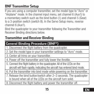
Transmitter and Receiver Binding
BNF Transmitter SetupIf you are using a computer transmitter, set the model type to “Acro” or “Airplane” mode. In the channel input menu, set channel 6 (Aux1) to a momentary switch such as the bind button ( I ) and channel 5 (Gear) to a 3-position switch (switch B). In the Servo Setup menu, reverse channel 6 (Aux1).Bind the quadcopter to your transmitter following the Transmitter and Receiver Binding directions below.
General Binding Procedure (BNF®)1. Disconnect the flight battery from the quadcopter.2. Set the model type in your transmitter settings to “Acro” mode.3. Center all trims on your transmitter.4. Power off the transmitter and fully lower the throttle.5. Connect the flight battery in the quadcopter. All of the LEDs on the
aircraft will flash rapidly, indicating the aircraft has entered bind mode.6. Put the transmitter into bind mode while powering on the transmitter.7. Release the bind button/switch after 2–3 seconds. The quadcopter
is bound when all of the LEDs on the aircraft turn solid.8. Disconnect the flight battery and power the transmitter off.

16EN
If you encounter problems binding either the included RTF transmitter or your computer radio, obey the binding instructions and refer to the troubleshooting guide for other instructions. If needed, contact the appropriate Horizon Product Support office.
Your RTF transmitter comes prebound to the quadcopter. If you need to re-bind, follow the directions below.MLP6DSM Binding Procedure (RTF)1. Disconnect the flight battery from the quadcopter.2. Center all trims on your transmitter.3. Power off the transmitter and fully lower the throttle.4. Connect the flight battery in the quadcopter. All of the LEDs on the
aircraft will flash rapidly, indicating the aircraft has entered bind mode.5. Push in and hold down the left stick while powering on the transmitter
(you will hear a ‘click’ and a long tone).6. Release the left stick. The transmitter will beep and the power LED
will blink. The quadcopter is bound when all of the LEDs on the aircraft turn solid.
7. Disconnect the flight battery and power the transmitter off.

17 EN
Transmitter Control (RTF)
Flight mode switch
Dual rate switch
ON/OFF Switch
Bind switch Power LED/fl ight mode indicator
DE
C
B
A
F
Meow Mode/Arming Switch

18EN
Adjusting Flight TrimsWhen pressed down, trim buttons make a sound that increases or decreases in pitch at each pressing. The middle or neutral trim position is heard as a middle tone in the pitch range of the sounds. The end of the control range is sounded by a series of beeps.
Dual Rate SelectionThe control sensitivity can be changed by pressing and releasing the right control stick. The LED on the transmitter will show solid for high sensitivity (default) and flashing for low sensitivity.
Mode 1 Mode 2
A Rudder (Left/Right) Elevator (Up/Down)
Rudder (Left/Right) Throttle/Collective (Up/Down)
B Rudder Trim Rudder TrimC Elevator Trim Throttle Trim
D Aileron (Left/Right) Throttle/Collective (Up/Down)
Aileron (Left/Right) Elevator (Up/Down)
E Aileron Trim Aileron TrimF Throttle Trim Elevator Trim
19 EN
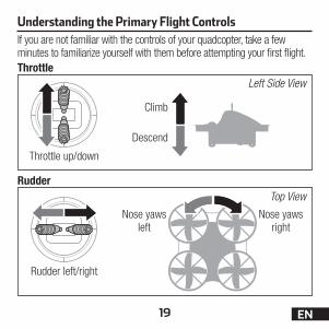
Understanding the Primary Flight ControlsIf you are not familiar with the controls of your quadcopter, take a few minutes to familiarize yourself with them before attempting your first flight.Throttle
Rudder
Left Side View
Top View
Climb
Nose yaws right
Nose yaws left
Descend
Throttle up/down
Rudder left/right

20EN
Elevator
Aileron
Left Side View
Rear View
Pitches Forward
Rolls Left
Pitches Backward
Rolls RightAileron left/right
Elevator up/down
21 EN
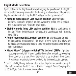
Flight Mode SelectionCycle between the flight modes by changing the position of the flight mode switch as programmed in the binding section above. The active flight mode is indicated by the LED taillight on the quadcopter*.•A ltitude mode (green LED, switch position 0): maintains
altitude. The bank angle is limited. When the sticks are released, the quadcopter will return to level flight.
•S tability mode (blue LED, switch position 1): the bank angle is limited. When the sticks are released, the quadcopter will return to level flight.
•A gility mode (red LED, switch position 2): the quadcopter has no bank angle limits and will not return to level fight if the sticks are released. Use rates and expo to tune the performance according to your flying style.
•M eow Mode™ (trigger switch (RTF), button I (BNF)): flips the quadcopter upright if it lands upside down after a crash by reversing the motors on one side. Press the switch once to disarm the motors. Press again to activate Meow Mode to flip the quadcopter upright.
* The LED taillight only indicates the active flight mode continuously if the color mode of the LED has not been changed. See Changing the LED Taillight Color for more information.

22EN
The LEDs indicate the front and back of the quadcopter. The white LEDs indicate the front. The red LEDs and tail light indicate the back.TakeoffArm the motors by pressing the arming switch. Increase the throttle until the model is approximately 2 ft. (600mm) off the ground in a low-level hover and concentrate on balancing the throttle stick’s position so that the quadcopter holds a steady hover altitude. In some cases, you may need to make a few short “hops” to an altitude of just a few inches until you be-come familiar with the control inputs and trim settings required to maintain a steady hover and altitude. HoveringThe Inductrix® quadcopter requires minor throttle adjustments to maintain its altitude in hover. Remember to keep these throttle adjustments as minimal as possible. Large adjustments could result in a loss of control or a possible crash.While attempting to establish a low-level hover, check to see if any trim adjustments are required to keep the quadcopter from drifting in various directions. If you find that it constantly drifts without any directional control input, land the model before making any adjustments to the trim settings.•If the nose of the quadcopter rotates to the left or right, adjust the
rudder trim in the opposite direction.
Fly the Quadcopter

23 EN
•If the quadcopter continually drifts forward or backward, adjust the elevator trim in the opposite direction.
•If the quadcopter continually drifts to the left or right, adjust the aileron trim in the opposite direction.
Continue making minor trim adjustments until the machine hovers at a low altitude with very little drifting and directional control input. If this is your first multicopter or helicopter, seek the help of an experienced pilot to trim the model for you before making your first flight.With your quadcopter properly trimmed and maintaining a stable low-level hover, practice using the rudder, elevator and aileron controls to familiarize yourself with the machine’s responses to control inputs. Remember to keep the control inputs as minimal as possible.Average flight times are approximately 4 minutes.
LandingTo land the quadcopter, establish a low level hover. Slowly lower the throttle until the quadcopter touches down.After landing, press the arming button to disarm the motors.Unplug and remove the flight battery.To prevent excessive wear to the motors, always allow the motors to cool between flights.
NOTICE: Crash damage is not covered under warranty.

24EN
Low Voltage Cutoff (LVC)Once the battery reaches 3V under load, the ESC will continuously lower power sup-plied to the motor until complete shutdown occurs. This helps prevent over-discharge of the Li-Po battery. Land immediately once the ESC activates LVC. Continuing to fly after LVC can damage the battery, cause a crash or both. Crash damage and batter-ies damaged due to over-discharge are not covered under warranty.Repeatedly flying the aircraft until LVC activates will damage the flight battery. Disconnect and remove the Li-Po battery from the aircraft after use to prevent trickle discharge. During storage, make sure the battery charge does not fall below 3V per cell.
Battery Level IndicatorWhen first powered on, the quadcopter indicates the charge level of the flight battery by lighting the center LED taillight briefly.
Taillight Color Battery Charge LevelGreen fully chargedYellow partially chargedRed discharged, do not fly
After the flight battery charge level is shown, the LED taillight indicates the active flight mode or the alternate chosen color as described in the Changing the Center LED Taillight Color section.

25 EN
Changing the Center LED Taillight Color To change the color of the center LED taillight:1. Power on the transmitter.2. Power on the quadcopter. DO NOT arm the motors.3. Push both transmitter sticks fully forward and hold for 3 seconds.
The taillight on the quadcopter will flash continuously.4. Push the aileron stick right or left to choose the desired taillight color.5. Pull both transmitter sticks fully back and hold for 1 second to save
the desired color. The taillight will now display the chosen color continuously. It will show the active flight mode for approximately 1 second after changing flight modes.
To reset the taillight to the default flight mode indicator color mode:1. Power on the transmitter.2. Power on the quadcopter. DO NOT arm the motors.3. Pull both transmitter sticks fully backward and hold for 5 seconds.
The taillight will change color to the active flight mode.

26EN
NOTICE: Consult local laws and ordinances before operating FPV (fi rst person view) equipment. In some areas, FPV operation may be limited or prohibited. You are responsible for operating this product in a legal and responsible manner.
FPV Camera and Video Transmitter
1. Power on your radio transmitter, then power on the aircraft.
2. Power on the video receiver to make sure the channel is clear.
3. Select the desired video transmitter band by pressing and holding the button on the quadcopter as shown for 3 seconds to scroll through the available bands (A, B, E*, F and R). The active band is indicated by the fl ashing blue LED.
4. Scroll through the channels (1-8) in each band by pressing and releasing the button. Channel 1 is indicated by the red internal LED on the quadcopter glowing solid. The red LED will blink every time the button is pushed. When the LED glows solid again, the transmitter is back to channel 1.
5. Perform a range test before fl ying.
* Band E is not available for use outside of North America and must be unlocked for use in the stock video transmitter. Consult your local laws prior to attempting to access Band E. See Accessing Band E to unlock Band E in the video transmitter.

27 EN
Available Frequencies (mHz)Band CH 1 CH 2 CH 3 CH 4 CH 5 CH 6 CH 7 CH 8
Band A 5865 5845 5825 5805 5785 5765 5745 5745Band B 5733 5752 5771 5790 5809 5828 5847 5866FS/IRC 5740 5760 5780 5800 5820 5840 5860 5860RaceBand 5732 5732 5732 5769 5806 5843 5843 5843
Video Transmitter LED layout
Channel (red)
Bands (blue)
If you experience static in the video feed, select a different channel.NOTICE: The 25mW micro video transmitter range on your quadcopter is less than your fl ight control transmitter range. Ensure you have adequate video camera range for fi lming.
Tip: If you are fl ying with an FPV headset and are prone to motion sickness, sit in a chair. If you start to suffer from motion sickness while fl ying, lower your chin against your chest.Fly in open areas, away from people, trees, cars, and buildings. The range of the system can be impacted by any obstructions blocking your signal. It is normal to see break up in the video going behind trees and other obstacles.
LED windows

28EN
75%
Band E 5705 5685 5665 5665 5885 5905 5905 5905
Accessing Band EIf local laws allow their use, the following frequencies in Band E are available:
To access Band E press and hold the camera button for at least 8 seconds. The blue band LED will glow solid. All 5 bands are now available. Scroll through the bands normally, as described in step 3 above.
Video Monitor (RTF)5.8GHz Antenna connectorMenu Buttons:
Use the + and – buttons to modify:Brightness ContrastColor Mode (16:9, 4:3)Language Reset
Channel Selection ButtonSingle push to change channel
Frequency Band ButtonSingle push to change band
Micro Memory Card SlotON/Off SwitchCharge Status LED
Red = charging Green = charged
AV In
5V Micro USB Charge Port

29 EN
CAUTION: Do not power the monitor on without the antenna attached. Doing so will damage the video transmitter and
receiver amplifiers. Amplifier damage is not covered by warranty.
1. Before using the Spektrum™ 4.3 inch Video Monitor make sure the monitor is charged thoroughly. Connect the micro USB connector to a 5V USB power source. The charge indicator LED will glow red while charging and green when the monitor is fully charged.
2. Attach the included antenna to the antenna connector located on the top of the monitor.

30EN
a
bc
3. Attach the FPV monitor holder to the MLP6DSM transmitter.a. Slide the holder down over
the antenna.b. Tighten the clamp screw.
Do not overtighten.c. Open the clamp jaws and
place the monitor in the jaws. The angle of the monitor can be adjusted by loosening the angle adjustment knob, rotat-ing the clamp up or down and tightening the adjustment knob.
4. Insert a micro memory card (not included) in the slot on the side of the video monitor. Press the card in until it locks. To remove the card, press in slightly and release until the card is released.Always insert the memory card before powering on the video monitor.
5. Power on the video monitor and look for a clear channel. Clear channels will have a consistent static background. Channels with interference will display horizontal static lines. Select one of the clear channels.
6. Once you have chosen a clear channel on the monitor, select the same channel on the video transmitter.

31 EN
When powered on, the video monitor is in FPV mode. The buttons have the following functions while the monitor is in the various video modes:FPV mode •CH Button: Press once to change the channel. Press and hold for
approximately 3 seconds to auto scan available channels.•FR Button: Press once to change the frequency band. Press and
hold for approximately 3 seconds to auto scan.•M Button: Press once to access the on-screen menu. Press again
to exit the on-screen menu.•– and + Buttons: Press to decrease or increase speaker volume
and to adjust menu selections.•Back Panel Button: Press once to start recording to the DVR.
Press again to stop recording. Press and hold to change from FPV mode to DVR mode.
DVR play-back mode •CH Button: No function.•FR Button: Press once to change between DVR record mode and
DVR playback mode.

32EN
•M Button: Press once to enter/exit the on-screen menu. While in the menu, use the back panel button to higlight the desired selec-tion and the – and + buttons to adjust the settings.
•– and + Buttons: Press to scroll through recorded files. •Back Panel Button: Press once to play the selected file. Press
again to pause/resume the playback.DVR recording mode: •CH Button: No function.•FR Button: Press once to change between DVR record mode and
DVR playback mode. •M Button: No function.•– and + Buttons: No function.•Back Panel Button: Press to start/stop recording to the DVR.
AV IN mode:•CH Button: No function.•FR Button: No function.•M Button: Press once to access the on-screen menu. Press again
to exit the on-screen menu.•– and + Buttons: Press to decrease or increase speaker volume
and to adjust menu selections.•Back Panel Button: Press to start/stop recording to the DVR.

33 EN
Troubleshooting Guide
Problem Possible Cause Solution
Will not respond to throttle
Throttle too high and/or throttle trim is too high
Reset controls with the throttle stick and throttle trim at the lowest setting
Does not function and smells burnt after connecting the flight battery
Flight battery con-nected with the wrong polarity
Replace the 3-in-1 board. Con-nect the flight battery noting proper polarity
LED on receiver flashes rapidly and quadcopter will not respond to transmitter (during binding)
Transmitter too near aircraft during binding process
Power off the transmitter. Move the transmitter a larger distance from the aircraft. Disconnect and recon-nect the flight battery to the aircraft. Follow the binding instructions
Bind switch or button was not held while transmitter was pow-ered on
Power off transmitter and re-peat bind process
Aircraft or transmitter is too close to large metal object, wireless source or another transmitter
Move aircraft and transmitter to another location and attempt binding again

34EN
Problem Possible Cause Solution
LED on the receiver flashes rapidly and the quadcopter will not respond to the transmitter (after binding)
Less than a 5-second wait between first powering on the trans-mitter and connecting the flight battery to the quadcopter
Leave the transmitter powered on. Disconnect and recon-nect the flight battery to the quadcopter
The quadcopter is bound to a different model memory (ModelMatch™ transmitters only)
Select the correct model memory on the transmitter. Disconnect and reconnect the flight battery to the quadcopter
Flight battery or trans-mitter battery charge is too low
Replace or recharge batteries
Aircraft or transmitter is too close to large metal object, wireless source or another transmitter
Move aircraft and transmitter to another location and attempt connecting again
Crashes immedi-ately upon lift-off or doesn’t lift off
Propellers in wrong locations Make necessary adjustments
35 EN
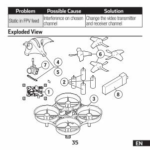
Exploded View
83
4
5
6
1
7
2
Problem Possible Cause Solution
Static in FPV feed Interference on chosen channel
Change the video transmitter and receiver channel
36EN
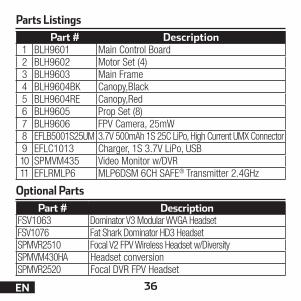
Parts Listings
Optional PartsPart # Description
FSV1063 Dominator V3 Modular WVGA HeadsetFSV1076 Fat Shark Dominator HD3 HeadsetSPMVR2510 Focal V2 FPV Wireless Headset w/DiversitySPMVM430HA Headset conversionSPMVR2520 Focal DVR FPV Headset
Part # Description1 BLH9601 Main Control Board2 BLH9602 Motor Set (4)3 BLH9603 Main Frame4 BLH9604BK Canopy,Black5 BLH9604RE Canopy,Red6 BLH9605 Prop Set (8)7 BLH9606 FPV Camera, 25mW8 EFLB5001S25UM 3.7V 500mAh 1S 25C LiPo, High Current UMX Connector9 EFLC1013 Charger, 1S 3.7V LiPo, USB10 SPMVM435 Video Monitor w/DVR11 EFLRMLP6 MLP6DSM 6CH SAFE® Transmitter 2.4GHz

37 EN
Limited WarrantyWhat this Warranty CoversHorizon Hobby, LLC, (Horizon) warrants to the original purchaser that the product purchased (the “Product”) will be free from defects in materials and workmanship at the date of purchase.What is Not CoveredThis warranty is not transferable and does not cover (i) cosmetic damage, (ii) damage due to acts of God, accident, misuse, abuse, negligence, commercial use, or due to improper use, installation, operation or maintenance, (iii) modification of or to any part of the Product, (iv) attempted service by anyone other than a Horizon Hobby autho-rized service center, (v) Product not purchased from an authorized Horizon dealer, (vi) Product not compliant with applicable technical regulations, or (vii) use that violates any applicable laws, rules, or regulations.OTHER THAN THE EXPRESS WARRANTY ABOVE, HORIZON MAKES NO OTHER WARRANTY OR REPRESENTATION, AND HEREBY DISCLAIMS ANY AND ALL IMPLIED WARRANTIES, INCLUDING, WITHOUT LIMITATION, THE IMPLIED WARRANTIES OF NON-INFRINGEMENT, MERCHANTABILITY AND FITNESS FOR A PARTICULAR PURPOSE. THE PURCHASER ACKNOWLEDGES THAT THEY ALONE HAVE DETERMINED THAT THE PRODUCT WILL SUITABLY MEET THE REQUIREMENTS OF THE PURCHASER’S INTENDED USE. Purchaser’s RemedyHorizon’s sole obligation and purchaser’s sole and exclusive remedy shall be that Horizon will, at its option, either (i) service, or (ii) replace, any Product determined by

38EN
Horizon to be defective. Horizon reserves the right to inspect any and all Product(s) involved in a warranty claim. Service or replacement decisions are at the sole discretion of Horizon. Proof of purchase is required for all warranty claims. SERVICE OR REPLACEMENT AS PROVIDED UNDER THIS WARRANTY IS THE PURCHASER’S SOLE AND EXCLUSIVE REMEDY. Limitation of LiabilityHORIZON SHALL NOT BE LIABLE FOR SPECIAL, INDIRECT, INCIDENTAL OR CONSEQUENTIAL DAMAGES, LOSS OF PROFITS OR PRODUCTION OR COMMERCIAL LOSS IN ANY WAY, REGARDLESS OF WHETHER SUCH CLAIM IS BASED IN CONTRACT, WARRANTY, TORT, NEGLIGENCE, STRICT LIABILITY OR ANY OTHER THEORY OF LIABILITY, EVEN IF HORIZON HAS BEEN ADVISED OF THE POSSIBILITY OF SUCH DAMAGES. Further, in no event shall the liability of Horizon exceed the individual price of the Product on which liability is asserted. As Horizon has no control over use, setup, final assembly, modification or misuse, no liability shall be assumed nor accept-ed for any resulting damage or injury. By the act of use, setup or assembly, the user accepts all resulting liability. If you as the purchaser or user are not prepared to accept the liability associated with the use of the Product, purchaser is advised to return the Product immediately in new and unused condition to the place of purchase.LawThese terms are governed by Illinois law (without regard to conflict of law principals). This warranty gives you specific legal rights, and you may also have other rights which vary from state to state. Horizon reserves the right to change or modify this warranty at any time without notice.

39 EN
WARRANTY SERVICESQuestions, Assistance, and ServicesYour local hobby store and/or place of purchase cannot provide warranty support or service. Once assembly, setup or use of the Product has been started, you must contact your local distributor or Horizon directly. This will enable Horizon to better answer your questions and service you in the event that you may need any assistance. For questions or assistance, please visit our website at www.horizonhobby.com, submit a Product Support Inquiry, or call the toll free telephone number referenced in the Warranty and Service Contact Information section to speak with a Product Support representative.Inspection or ServicesIf this Product needs to be inspected or serviced and is compliant in the country you live and use the Product in, please use the Horizon Online Service Request submis-sion process found on our website or call Horizon to obtain a Return Merchandise Authorization (RMA) number. Pack the Product securely using a shipping carton. Please note that original boxes may be included, but are not designed to withstand the rigors of shipping without additional protection. Ship via a carrier that provides tracking and insurance for lost or damaged parcels, as Horizon is not responsible for merchandise until it arrives and is accepted at our facility. An Online Service Request is available at http://www.horizonhobby.com/content/service-center_render-service-center. If you do not have internet access, please contact Horizon Product Support to obtain a RMA number along with instructions for submitting your product for service. When calling Horizon, you will be asked to provide your complete name, street address, email address and phone number where you can be reached during busi-ness hours. When sending product into Horizon, please include your RMA number, a

40EN
list of the included items, and a brief summary of the problem. A copy of your original sales receipt must be included for warranty consideration. Be sure your name, address, and RMA number are clearly written on the outside of the shipping carton. NOTICE: Do not ship LiPo batteries to Horizon. If you have any issue with a LiPo battery, please contact the appropriate Horizon Product Support office.Warranty Requirements For Warranty consideration, you must include your original sales receipt verifying the proof-of-purchase date. Provided warranty conditions have been met, your Product will be serviced or replaced free of charge. Service or replacement decisions are at the sole discretion of Horizon.Non-Warranty ServiceShould your service not be covered by warranty, service will be completed and payment will be required without notification or estimate of the expense unless the expense exceeds 50% of the retail purchase cost. By submitting the item for service you are agreeing to payment of the service without notification. Service estimates are available upon request. You must include this request with your item submitted for service. Non-warranty service estimates will be billed a minimum of ½ hour of labor. In addition you will be billed for return freight. Horizon accepts money orders and cashier’s checks, as well as Visa, MasterCard, American Express, and Discover cards. By submitting any item to Horizon for service, you are agreeing to Horizon’s Terms and Conditions found on our website http://www.horizonhobby.com/content/service-center_render-service-center.
EN

41 EN
Warranty and Service Contact Information
Horizon Hobby Contact Information Address
Horizon Service Center(Repairs and Repair Re-quests)
servicecenter. horizonhobby.com/ RequestForm/
4105 Fieldstone Rd Champaign, Illinois 61822 USA
Horizon Product Support(Product Technical As-sistance)
productsupport @horizonhobby.com877-504-0233
Saleswebsales @horizonhobby.com800-338-4639
ATTENTION: Horizon service is limited to Product compliant in the country of use and ownership. If received, a non-compliant Product will not be serviced. Further, the sender will be respon-sible for arranging return shipment of the un-serviced Product, through a carrier of the sender’s choice and at the sender’s expense. Horizon will hold non-compliant Product for a period of 60 days from notification, after which it will be discarded. 10/15
United States of America
EN

FCC ID: BRWDXMTX10, BRWBLH9600This equipment has been tested and found to comply with the limits for Part 15 of the FCC rules. These limits are designed to provide reasonable protection against harmful interference in a residential installation. This equipment generates uses and can radiate radio frequency energy and, if not installed and used in accordance with the instructions, may cause harmful interference to radio communications.However, there is no guarantee that interference will not occur in a particular installation. If this equipment does cause harmful interference to radio or television reception, which can be determined by turning the equipment off and on, the user is encouraged to try to correct the interference by one or more of the following measures:•Reorient or relocate the receiving antenna.•Increase the separation between the equipment and receiver.•Connect the equipment to an outlet on a circuit different from that to
which the receiver is connected.
FCC Information
European Union
Horizon Hobby Contact Information Address
Horizon Technischer Service [email protected] Hanskampring 9 D 22885 Barsbüttel GermanySales: Horizon Hobby GmbH +49 (0) 4121 2655 100

This device complies with part 15 of the FCC rules. Operation is subject to the following two conditions: (1) This device may not cause harmful interference, and (2) this device must accept any interference received, including interference that may cause undesired operation.
NOTICE: Modifications to this product will void the user’s authority to operate this equipment.
IC InformationIC: 6157A-BRWDXMT, 6157A-BLH9600This device complies with Industry Canada licence-exempt RSS standard(s). Operation is subject to the following two conditions: (1) this device may not cause interference, and (2) this device must accept any interference, including interference that may cause undesired operation of the device.”
Antenna Separation DistanceWhen operating your transmitter, please be sure to maintain a separation distance of at least 5 cm between your body (excluding fingers, hands, wrists, ankles and feet) and the antenna to meet RF exposure safety requirements as determined by FCC regulations.

44EN
Compliance Information for the European Union
Inductrix FPV+ RTF (BLH9600)EU Compliance Statement:Horizon Hobby, LLC hereby declares that this product is in compliance with the essential requirements and other relevant provisions of the RED and EMC Directives.
Inductrix FPV+ BNF Basic (BLH9680)EU Compliance Statement:Horizon Hobby, LLC hereby declares that this product is in compliance with the essential requirements and other relevant provisions of the RED Directive.A copy of the EU Declaration of Conformity is available online at: http://www.horizonhobby.com/content/support-render-compliance.

45 EN
Instructions for disposal of WEEE by users in the European UnionThis product must not be disposed of with other waste. Instead, it is the user’s responsibility to dispose of their waste equipment by handing it over to a designated collections
point for the recycling of waste electrical and electronic equipment. The separate collection and recycling of your waste equipment at the time of disposal will help to conserve natural resources and make sure that it is recycled in a manner that protects human health and the environ-ment. For more information about where you can drop off your waste equipment for recycling, please contact your local city office, your household waste disposal service or where you purchased the product.

©2017 Horizon Hobby, LLC. Blade, E-flite, Inductrix, Meow Mode, DSM, DSM2, DSMX, Bind-N-Fly, BNF, the BNF logo,
SAFE, ModelMatch, Focal, and the Horizon Hobby logo are trademarks or registered trademarks of Horizon Hobby, LLC.
The Spektrum trademark is used with permission of Bachmann Industries, Inc. All other trademarks, service marks or logos are property of their respective owners.
Created 07/17 56125 BLH9600/BLH9680