instruction manual bite 2 and bite 2p€¦ · the maximum measurement is 200 mΩ. impedance...
TRANSCRIPT

AVTM246004 July 2011
Rev. 4
Instruction Manual BITE 2 and BITE 2P
Battery Impedance Test Equipment
(Includes AVOLink Addendum)
BITE 2: Catalog No. 246002B
BITE 2P: Catalog No. 246004
HIGH-VOLTAGE EQUIPMENT Read this entire manual before operating.
APARATO DE ALTO VOLTAJE Ante de operar este producto lea este manual enteramente.
M 2621 Van Buren Ave Norristown, PA 19403-2329 610-676-8500 www.megger.com


BITE 2 and BITE 2P
Battery Impedance Test Equipment
Instruction Manual

Copyright© 2003 by Megger. All rights reserved. The information presented in this manual is believed to be adequate for the intended use of the product. If the product or its individual instruments are used for purposes other than those specified herein, confirmation of their validity and suitability must be obtained from Megger. Refer to the warranty information below. Specifications are subject to change without notice. WARRANTY Products supplied by Megger are warranted against defects in material and workmanship for a period of one year following shipment. Our liability is specifically limited to replacing or repairing, at our option, defective equipment. Equipment returned to the factory for repair must be shipped prepaid and insured. Contact your MEGGER representative for instructions and a return authorization (RA) number. Please indicate all pertinent information, including problem symptoms. Also specify the serial number and the catalog number of the unit. This warranty does not include batteries, lamps or other expendable items, where the original manufacturer’s warranty shall apply. We make no other warranty. The warranty is void in the event of abuse (failure to follow recommended operating procedures) or failure by the customer to perform specific maintenance as indicated in this manual. M 2621 Van Buren Ave Norristown, PA 19403-2329 610-676-8500 (Telephone) 610-676-8610 (Fax) www.megger.com email: [email protected]

M
AVTM246004 BITE 2/2P Rev 4 July 2011
i
Contents INTRODUCTION ........................................................................................................................... 1
About the BITE 2 and BITE 2P…................................................................................................ 1 How the BITE 2/2P Works........................................................................................................... 2 Applications for the BITE 2/2P .................................................................................................... 3 BITE 2/2P Measurements............................................................................................................. 4 Upon Receipt of the BITE 2/2P.................................................................................................... 4 Safety First ................................................................................................................................... 6 How to Use This Manual.............................................................................................................. 7
Typographic Conventions..................................................................................................... 7 SAFETY.......................................................................................................................................... 9
Overview ..................................................................................................................................... 9 Safety Requirements .................................................................................................................... 9 Connection to Power Source....................................................................................................... 11 Fuse Replacement ...................................................................................................................... 11 Cautions and Warnings............................................................................................................... 11
CONTROLS, CONNECTORS, INDICATORS AND MENUS...................................................... 13 Overview ................................................................................................................................... 13
BITE 2 Transmitter..............................................................................................................14 BITE 2P Transmitter ...........................................................................................................16 Receiver ..............................................................................................................................18 Receiver Keys .....................................................................................................................19 Receiver Reset Switch .........................................................................................................24
STANDARD TEST PROCEDURE................................................................................................ 25 Overview ................................................................................................................................... 25 Step One: Prepare for Testing..................................................................................................... 27 Step Two: Powering-on the Receiver.......................................................................................... 28 Step Three: Scanning Test Information with the Wand (Optional) ................................................ 30
If You Do Not Want to Scan Information Using the Wand ..................................................30 If You Want to Scan Information Using the Wand ...............................................................30
Step Four: Setting Baseline, Warning and Fail Values ................................................................ 32 Step Five: Splitting the Strap (if needed) .................................................................................... 33
If You Do Not Want to Split the Strap .................................................................................33 If You Want to Split the Strap..............................................................................................33
Step Six: Connecting the Receiver and the BITE 2 or BITE 2P Transmitter to the Battery.......... 35 Connecting the BITE 2 or BITE 2P Transmitter...................................................................37
Step Seven: Measuring the Cell and the Strap............................................................................. 38 Measuring the Next Section of a Sectioned Battery String ...................................................42
Step Eight: What to Do When the Test Is Complete ................................................................... 43 Reviewing a Test .................................................................................................................43 Retesting Cells and Straps ...................................................................................................44 Printing an Active Test to Review the Data (BITE 2P).........................................................44
Powering Down and Disconnecting the BITE 2/2P..................................................................... 45
M
AVTM246004 BITE 2/2P Rev 4 July 2011
ii
MODIFIED PROCEDURES FOR SPECIAL CONDITIONS.........................................................47 Overview ....................................................................................................................................47 Reversing the Current Source Leads............................................................................................47 Verifying the Source Current ......................................................................................................48
Sectioning a Battery System................................................................................................49 TRANSFERRING, PRINTING, AND DELETING TEST RESULTS ............................................55
Overview ....................................................................................................................................55 Exporting Test Results from the Receiver to a PC.......................................................................56 Printing Test Results in the BITE 2P Transmitter Printer.............................................................58 Deleting Test Results from the Receiver......................................................................................59
INTERPRETING TEST RESULTS................................................................................................61 Overview ....................................................................................................................................61 Instantaneous Interpretation ........................................................................................................62 Short-Term Interpretation............................................................................................................63 Long-Term Interpretation............................................................................................................63 Temperature Corrections .............................................................................................................64
SETTING OPTIONS......................................................................................................................67 Overview ....................................................................................................................................67 Turning the Receiver Backlight ON and OFF..............................................................................68 Adjusting the Receiver Screen Contrast.......................................................................................68 Selecting the Receiver Language.................................................................................................69 Setting the Receiver Clock ..........................................................................................................69 Selecting the Line Frequency ......................................................................................................71
MAINTENANCE AND TROUBLESHOOTING ...........................................................................73 Overview ....................................................................................................................................73 Cleaning and Inspecting the BITE 2 and BITE 2P.......................................................................74 Charging the Receiver .................................................................................................................74 Replacing Batteries in the Receiver .............................................................................................75 Maintaining the Receiver Charger in the BITE 2 and BITE 2P....................................................78 Maintaining Fuses in the BITE 2 and BITE 2P Transmitters .......................................................78
Verifying a Transmitter Fuse Problem.................................................................................79 Replacing Fuses in the BITE 2 Transmitter .........................................................................82 Replacing Fuses in the BITE 2P Transmitter .......................................................................85
Interpreting Error Messages ........................................................................................................88 If the BITE 2 or BITE 2P Needs Repairs.....................................................................................88
OPTIONAL EQUIPMENT.............................................................................................................89 Available Options .......................................................................................................................89
APPENDIX A: TECHNICAL SPECIFICATIONS .........................................................................91 Application .................................................................................................................................91 Electrical.....................................................................................................................................91
BITE 2 and BITE 2P Transmitters.......................................................................................91 Receiver ..............................................................................................................................92 Fuses ...................................................................................................................................93
Mechanical .................................................................................................................................93 Environmental.............................................................................................................................94 Accessories - Standard ................................................................................................................95
CONTENTS
AVTM246004 BITE 2/2P Rev 4 July 2011
iii
APPENDIX B: REPLACEABLE PARTS...................................................................................... 97 Catalog Numbers 246002B and 246004...................................................................................... 97 Catalog Numbers 246002B and 246004...................................................................................... 98 How to Order Replaceable Parts for the BITE 2/2P .................................................................... 98
GLOSSARY .................................................................................................................................. 99 INDEX......................................................................................................................................... 101
Figures Figure 1-1: BITE 2 instrument......................................................................................................... 5 Figure 1-2: BITE 2P instrument ...................................................................................................... 6 Figure 3-1: BITE 2 transmitter ...................................................................................................... 14 Figure 3-2: BITE 2P transmitter .................................................................................................... 16 Figure 3-3: Voltage Selector Card Orientation............................................................................... 17 Figure 3-4: Receiver controls, connectors, and indicators .............................................................. 18 Figure 3-5: Flowchart for Receiver menus..................................................................................... 20 Figure 3-6: Flowchart for Receiver menus..................................................................................... 21 Figure 3-7: Flowchart for Receiver menus..................................................................................... 22 Figure 3-8: Receiver menu ............................................................................................................ 23 Figure 3-9: Receiver RESET switch .............................................................................................. 24 Figure 4-1: Receiver controls, connectors and indicators ............................................................... 28 Figure 4-2: Initialization screens ................................................................................................... 29 Figure 4-3: Scanning test information............................................................................................ 31 Figure 4-4: Receiver controls, connectors, and indicators .............................................................. 35 Figure 4-5: BITE 2/2P transmitter connected to the battery ........................................................... 36 Figure 4-6: Receiver and potential probe positioned on top of battery cell terminals ...................... 39 Figure 4-7: Receiver and potential probe positioned on top of battery strap terminals .................... 40 Figure 5-1: Reversing the current source leads on a single string of cells when a high
or low current message is displayed. ......................................................................... 48 Figure 5-2: Sectioning a battery system greater than 275 V ........................................................... 50 Figure 5-3: Sectioning a parallel string of cells .............................................................................. 52 Figure 6-1: Exporting data to a PC ................................................................................................ 57 Figure 6-2: Printing test results...................................................................................................... 58 Figure 6-3: Deleting test results from the Receiver ........................................................................ 60 Figure 7-1: Generic curve of impedance vs. cell life ...................................................................... 64 Figure 9-1: RTC battery "piggybacks" the system battery.............................................................. 77 Figure 9-2: BITE 2 transmitter secondary fuses (front view) ......................................................... 83 Figure 9-3: BITE 2P transmitter secondary fuses (front view) ....................................................... 86

M
AVTM246004 BITE 2/2P Rev 4 July 2011
iv
M

M
AVTM246004 BITE 2/2P Rev 4 July 2011
1
1
INTRODUCTION
About the BITE 2 and BITE 2P…
NOTE: Before attempting to use the BITE 2/2P, be sure that you read and understand the safety requirements and operating procedures contained in this manual.
Thank you for selecting an Megger product. This instrument has been thoroughly tested and inspected to meet rigid specifications before being shipped.
It is ready for use when set up and operated as described in this manual.
The BITE 2 and BITE 2P are testing instruments used to evaluate the condition of stationary battery strings. They measure the complete electrical path of the battery:
• internal ac impedance of each cell/jar in the string
• dc terminal voltage of each cell/jar
• interconnection resistance
These measurements, along with other maintenance data such as ambient and pilot cell temperatures and ac ripple currents, help determine the condition of a battery system.
The BITE 2/2P consists of a transmitter and a receiver that enable an operator to test for sulfating plates, post-strap corrosion, poor internal connections and poor intercell connections.

M
AVTM246004 BITE 2/2P Rev 4 July 2011
2
How the BITE 2/2P Works
Average impedance values for different types of batteries are available from Megger.
The operator connects the current source leads from the BITE 2/2P transmitter to a battery string so that an ac test current is capacitively coupled through the battery. It is best to test the battery string when it is operating at full float, that is, a constant charge level.
Then the operator uses the receiver to measure the voltage drop across the cell terminals. When the voltage drop across the cell is divided by the total ac current passing through the battery, the calculated value is impedance according to Ohm's Law. This impedance value gives the operator an indication of the overall condition of the cell, with high impedance typically indicating an unhealthy cell.
Several factors influence an impedance value, for instance, the size and type of cell, ambient and electrolyte temperature, and state of charge. Therefore, to determine the impedance of a healthy cell, the operator should measure a large number of similar cells under similar conditions and then calculate the average value. Deteriorating cells are easily identified by their higher-than-average impedance.
The BITE 2/2P also automatically measures and records the cell voltage and the time and date of the test. This voltage represents individual cell float voltage while measuring an operational string of cells.
The BITE 2/2P also measures intercell or strap connections and stores them with the cell impedance values. The BITE 2/2P can measure and record all aspects of the electrical path of the battery, including:
• location ID
• user ID
• test current
• total current
• internal cell impedance
• dc voltage
• intercell connector resistance
• specfic gravity
• time and date

INTRODUCTION
AVTM246004 BITE 2/2P Rev 4 July 2011
3
Applications for the BITE 2/2P
The BITE 2/2P measures the following battery types, ranging to 7000 Ah:
• lead-acid flooded cells
• sealed (VRLA) cells
• nickel-cadmium cells
The BITE 2/2P tests many system types, including:
• telecommunications
• substations
• UPS systems
• electrical power substations
• railroad signals and communications
• motive power batteries
• aircraft power supplies
• marine and military applications
• many others
For information about other installations that might benefit from impedance testing, contact Megger.

M
AVTM246004 BITE 2/2P Rev 4 July 2011
4
BITE 2/2P Measurements
Impedance readings are calibrated to 5 percent of reading over the specified temperature range. For ac impedance, the receiver screen presents data as ranges: 1.000, 10.00, and 100.0 mΩ. The maximum measurement is 200 mΩ.
Impedance precision (reproducibility) is 0.5%, and voltage precision is 0.5%.
Test numbers start with number one (001) and increment after each successful cell and strap reading. The operator initiates data acquisition by pulling a trigger on the receiver. The measurement range for dc voltage is from 1 to 25 V dc with an accuracy of 1 percent of reading.
Intercell (strap) and intertier connection measurements are made directly after the internal cell impedance measurement when STRAP is displayed on the LCD of the receiver. This feature provides resistance measurements in the same ranges as the cell/module impedance.
Total current is monitored with each impedance measurement to compute both cell and strap impedance and intercell (strap) resistance. The operator selects filtering in a menu in the receiver as either 50 Hz or 60 Hz depending on the line voltage.
A low current cutoff alarm is maintained at 3 A, and the maximum current allowed is 15 A. The LCD displays "Hi_A" to warn of an ac current over-range and "Lo_A" for current below 3 A.
Upon Receipt of the BITE 2/2P
Check the equipment received against the packing list to ensure that all materials are present. Notify Megger of any shortage (tel: 610-676-8500).
The BITE 2 instrument is shown in Figure 1-1. The BITE 2 includes the following components and accessories:
• transmitter with built-in receiver battery charger
• receiver

INTRODUCTION
AVTM246004 BITE 2/2P Rev 4 July 2011
5
• current source leads
• clamp-on current sensor (CT) with a 6-ft extension cable
• canvas carrying case for leads
• instruction manual
• null modem cable
Figure 1-1: BITE 2 instrument
The BITE 2P instrument is shown in Figure 1-2. The BITE 2P includes the following components and accessories:
• transmitter with built-in printer and receiver battery charger
• receiver
• current source leads
• clamp-on current sensor (CT) with a 6-ft extension cable
• instruction manual
• null modem cable

M
AVTM246004 BITE 2/2P Rev 4 July 2011
6
Figure 1-2: BITE 2P instrument
Safety First
Be sure to read the safety information in Chapter 2 thoroughly and observe all safety precautions and recommendations.

INTRODUCTION
AVTM246004 BITE 2/2P Rev 4 July 2011
7
How to Use This Manual
Typographic Conventions
• Figures and tables are numbered in sequence by section.
• Numbered lists show procedural steps.
• Bullets list items and options.
• Buttons represent elements on the BITE 2/2P control panel.
Cautions alert you to possible damage to equipment.
G CAUTION
Never allow water to enter the case of the BITE 2/2P.
Warnings alert you to conditions that are potentially hazardous to people.
F
WARNING Always power off and disconnect the BITE 2/2P before cleaning it.
Notes provide important information.
NOTE: If you do not want to test the strap, pull the trigger and go directly to Step Six.
Margin notes offer extra information and assistance.

M
AVTM246004 BITE 2/2P Rev 4 July 2011
8
M

M
AVTM246004 BITE 2/2P Rev 4 July 2011
9
2
SAFETY
Overview
The BITE 2 and BITE 2P and their recommended operating procedures have been designed with careful attention to safety. However, it is not possible to eliminate all hazards from electrical test equipment or to foresee every possible hazard that may occur. The user not only must follow the safety precautions contained in this manual, but also must carefully consider all safety aspects of the operation before proceeding.
Any use of electricity inherently involves some degree of safety hazard. While Megger has made every effort to reduce the hazard, the operator must assume responsibility for his or her own safety. Any work on batteries is hazardous and requires constant attention to safety. You should guard particularly against the possibility of acid spills, explosion, and electrical shock.
Safety Requirements
The BITE 2/2P test instrument has been designed to the IEC-1010-1 safety standard. Observe all industry standard safety rules for testing batteries.
• The BITE 2/2P transmitter is designed for connection to energized systems. Keep the BITE 2/2P transmitter S1 power switch set to O (OFF) or turn off the Current On/Off switch when connecting or disconnecting to the battery. Always wear rubber gloves during these operations.
• Always connect the source leads to the BITE 2/2P before connecting to the battery under test.

M
AVTM246004 BITE 2/2P Rev 4 July 2011
10
• Always remove the instrument test leads from the battery under test when not in use.
• The purpose of this equipment is limited to use as described in this manual. Do not use the equipment or its accessories for any purpose other than specifically described.
• To avoid electric shock hazard, operating personnel must not remove the protective instrument covers. Component replacement and internal adjustments must be made by qualified service personnel only.
• Do not operate in an explosive atmosphere. Explosive gases such as hydrogen can be present around batteries. A properly vented battery environment is considered safe, but it is the responsibility of the operator to verify conditions before using the BITE 2/2P.
• Wear protective clothing and eye protection to guard against skin and eye damage from battery acid or in the event of short-circuit sparking.
Replacement leads can be obtained from Megger.
• Ensure that test leads and probes are in good condition, clean, and free of broken or cracked insulation.
• Observe all cautions and warnings in this manual and on the equipment.
• This instrument is to be used only by suitably trained personnel who are familiar with the hazards involved in testing high voltage dc systems.
• Safety is the responsibility of the operator.

SAFETY
AVTM246004 BITE 2/2P Rev 4 July 2011
11
Connection to Power Source
The BITE 2/2P test instruments operate from a single-phase power source. The three-wire power cord requires a two-pole, three-terminal, live, neutral, and ground type connector. The voltage to ground from either pole of the power source must be 100 – 240 volts (50-60 Hz) nominal. Do NOT exceed 264 V max.
Before connecting to the ac power source, determine that the instrument rating matches the voltage of the power source and has a suitable two-pole, three-terminal grounding type connector.
The power input plug must be inserted only into a mating receptacle with a ground contact. Do not bypass the grounding connection. Any interruption of the grounding connection can create an electric shock hazard. Make sure that the receptacle is properly wired before inserting the plug.
Depending on whether the test set is supplied with a black, white and green input supply cord or a brown, blue and green/yellow supply cord, the black or brown cord lead must be connected to the live pole and the white or blue cord lead must be connected to the neutral pole of an approved power input plug. The green or green/yellow ground lead of the input supply cord must be connected to the protective ground (earth) contact of the input plug.
Fuse Replacement
See "Maintaining Fuses in the BITE 2 and BITE 2P Transmitters" on page 78 for detailed instructions on fuse replacement.
Refer fuse replacement to qualified personnel only. To avoid electric shock and fire hazard, use only the fuse specified (see Appendix B), which is identical with respect to type, voltage rating, and current rating.
Cautions and Warnings
This manual provides cautions and warnings where applicable, and these safety features should be strictly observed.

M
AVTM246004 BITE 2/2P Rev 4 July 2011
12
M

M
AVTM246004 BITE 2/2P Rev 4 July 2011
13
3
CONTROLS, CONNECTORS, INDICATORS AND MENUS
Overview
This chapter explains the locations and functions of the controls, connectors, indicators and menus for the BITE 2/BITE 2P transmitter and receiver. The first section covers the BITE 2 transmitter, the second covers the BITE 2P transmitter, and the third covers the receiver.

M
AVTM246004 BITE 2/2P Rev 4 July 2011
14
BITE 2 Transmitter
Figure 3-1 shows a front view of the BITE 2 transmitter.
Figure 3-1: BITE 2 transmitter
Digital Meter—ac source current digital indicator with a scale of 0 to 15 A.
Power Switch—The power switch is pressed to turn the transmitter on and off. The power switch is marked with | (for ON) and O (for OFF).
Current On/Off Switch—The current on/off switch is pressed to start or stop the flow of the test current to the battery.
Current On/Off Switch
Current Ready
Digital Meter
Control Panel
Power Switch
J3
J2
Over Voltage
Receiver Charger On/Off Indicator
Receiver Charger On/Off Indicator
J1 F1

CONTROLS, CONNECTORS, INDICATORS AND MENUS
AVTM246004 BITE 2/2P Rev 4 July 2011
15
Receiver Charger On/Off Indicator—LED illuminates when the receiver is plugged into the receiver and the charger is energized. It also indicates the state-of-charge of the receiver battery. While the battery is charging, the LED remains constant; when the battery is fully charged, the LED blinks.
Indicator Lamps:
CURRENT READY—Illuminates after the coupling capacitors in the transmitter are charged to the bus voltage. A delay timer allows current flow to the battery under test.
POWER—Illuminates whenever the Power Switch is in the | (ON) position and the unit is powered by 120 V (230 V) ac line voltage
OVER VOLTAGE—Indicates that the voltage across the current source leads is greater than 275 V dc. (The READY light will go out and the current flow to the battery will stop when an over-voltage condition occurs.)
Transmitter Connector Panel
Power module—The transmitter power module comprises the following components:
J1 receptacle—The standard power cord supplied with the instrument is inserted into this 120 V/60 Hz (230 V/50 Hz) receptacle for ac power.
F1 Fuse carrier/voltage selector—The fuse carrier is removed as needed to replace fuses. The arrow located on the connector panel directly to the left of the J1 receptacle should point to the indicator on the fuse carrier that corresponds to the proper voltage (120 V or 230 V). See Figure 3-3.
J2 connector—The transmitter current source leads are connected from this connector to the battery under test.
J3 connector—The receiver battery is charged from this connector to J3 on the receiver to charge its battery.

M
AVTM246004 BITE 2/2P Rev 4 July 2011
16
BITE 2P Transmitter
Figure 3-2 shows a front view of the BITE 2P transmitter.
Figure 3-2: BITE 2P transmitter
Digital Meter—ac source current indicator with a scale of 0 to 15 A.
Power Switch—The power switch is pressed to turn the transmitter on and off. The power switch is marked with a | (for ON) and an O (for OFF).
Current On/Off Switch—The current on/off switch is pressed to start or stop the flow of the test current to the battery.
Control Panel
Receiver Charger Current On/Off Switch
J2
Printer
Storage Bin
J3
Power Module
Power Switch
J1
Digital Meter
Over VoltageCurrent Ready
F1
J4
CONTROLS, CONNECTORS, INDICATORS AND MENUS
AVTM246004 BITE 2/2P Rev 4 July 2011
17
Indicator Lamps:
RECEIVER CHARGER ON/OFF—Illuminates when the receiver is plugged into J4 and the receiver charger is energized. It also indicates the state-of-charge of the receiver battery.
CURRENT READY—Illuminates after the coupling capacitors in the transmitter have been charged to the bus voltage. A delay timer allows current flow to the battery under test.
OVER VOLTAGE—Indicates that the voltage across the current source leads is greater than 275 V dc. (When an over-voltage condition occurs, the CURRENT READY light will go out and the current will stop being applied to the battery.)
J1 receptacle—The standard power cord supplied with the instrument is inserted into this 120 V (230 V) receptacle for ac power.
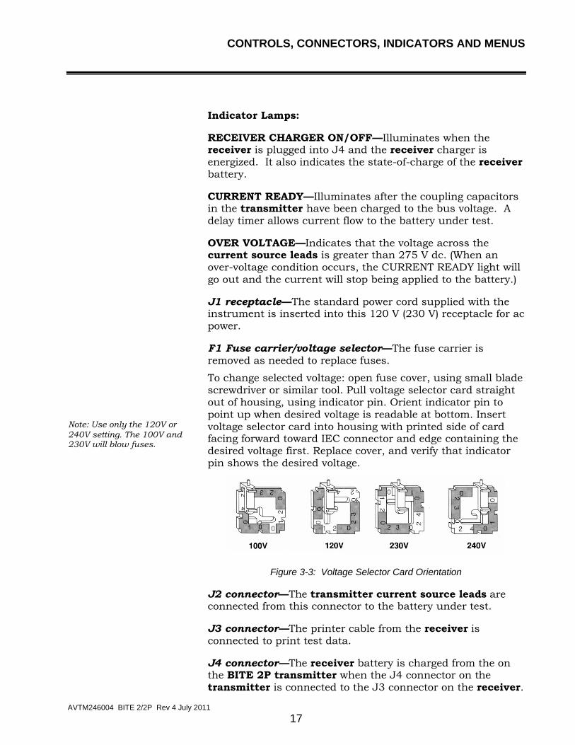
Note: Use only the 120V or 240V setting. The 100V and 230V will blow fuses.
F1 Fuse carrier/voltage selector—The fuse carrier is removed as needed to replace fuses.
To change selected voltage: open fuse cover, using small blade screwdriver or similar tool. Pull voltage selector card straight out of housing, using indicator pin. Orient indicator pin to point up when desired voltage is readable at bottom. Insert voltage selector card into housing with printed side of card facing forward toward IEC connector and edge containing the desired voltage first. Replace cover, and verify that indicator pin shows the desired voltage.
Figure 3-3: Voltage Selector Card Orientation
J2 connector—The transmitter current source leads are connected from this connector to the battery under test.
J3 connector—The printer cable from the receiver is connected to print test data.
J4 connector—The receiver battery is charged from the on the BITE 2P transmitter when the J4 connector on the transmitter is connected to the J3 connector on the receiver.

M
AVTM246004 BITE 2/2P Rev 4 July 2011
18
Receiver
The receiver is a universal device that can be used with the entire BITE product family. Figure 3-4 shows a front view of the receiver.
POWER ON Switch
ENTER Key
7-Pin Connector
4-Pin Connector
Potential Probe
3-Pin Connector
LCD
TRIGGER
UP and DOWN ARROW Keys
Figure 3-4: Receiver controls, connectors, and indicators
POWER ON switch—The POWER ON switch is pressed to power on the receiver. However, it is important to note that this switch does not power off the receiver. You must choose POWER DOWN from Menu 1.
LCD—The graphics-type LCD displays menu choices and receiver-related information. (See the following subsection, “Receiver Keys,” for information about keys associated with the screen.)
Potential probe—The potential probe is used in conjunction with the receiver to take cell impedance, voltage, and strap resistance measurements.
Trigger—The trigger is pulled to perform functions on the receiver, including entering test information.

CONTROLS, CONNECTORS, INDICATORS AND MENUS
AVTM246004 BITE 2/2P Rev 4 July 2011
19
7-pin connector—The 7-pin connector is used to insert one of the following: RS-232 communication cable, bar-code wand (optional), potential probe or printer.
4-pin connector—The 4-pin connector is used to connect the current sensor (CT).
3-pin connector—The 3-pin connector is used to connect the battery charger.
Buzzer—The buzzer prompts the user to input data. It also sounds under certain error conditions.
Receiver Keys
There are three keys located on the receiver that are used to operate the receiver and to navigate through the menus and displays on the LCD screen:
The UP ARROW and DOWN ARROW keys are used to select information displayed next to these keys on the screen. These keys are also used to scroll up and down through receiver screens.
The ENTER key is used to access receiver menus, which are shown in Figure 3-6 through Figure 3-7.

M
AVTM246004 BITE 2/2P Rev 4 July 2011
20
Figure 3-5: Flowchart for Receiver menus
Megger
COPYRIGHT 2000 RELEASE 2.0
Test Menu Structure
CONTROLS, CONNECTORS, INDICATORS AND MENUS
AVTM246004 BITE 2/2P Rev 4 July 2011
21
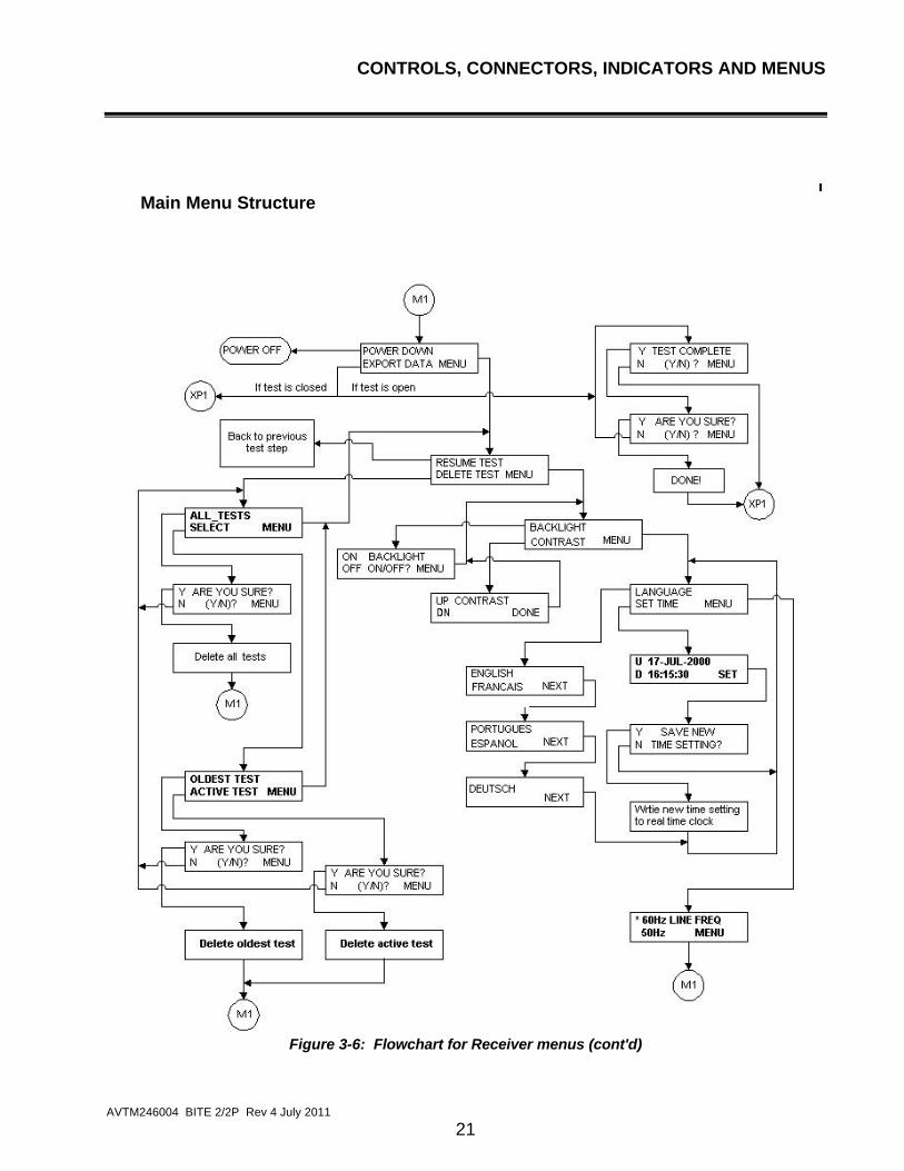
Figure 3-6: Flowchart for Receiver menus (cont'd)
Main Menu Structure

M
AVTM246004 BITE 2/2P Rev 4 July 2011
22
Figure 3-7: Flowchart for Receiver menus (cont’d)
Example of How to Use the Receiver Keys
1. Suppose that the following Menu is displayed on the
screen as shown in Figure 3-6.
2. To select EXPORT DATA, press .
3. However, to move from menu to menu, press
.
Print Menu Structure

CONTROLS, CONNECTORS, INDICATORS AND MENUS
AVTM246004 BITE 2/2P Rev 4 July 2011
23
Y TEST COMPLETE N (Y/N)? MENU
Figure 3-8: Receiver menu

M
AVTM246004 BITE 2/2P Rev 4 July 2011
24
Receiver Reset Switch
The RESET switch (see Figure 3-9), located on the receiver back panel, is only for Megger authorized calibration and repair. Activating the RESET switch de-energizes the receiver. Never use the RESET switch. It will result in permanent loss of data and loss of calibration.
Figure 3-9: Receiver RESET switch
RESET Switch

M
AVTM246004 BITE 2/2P Rev 4 July 2011
25
4
STANDARD TEST PROCEDURE
Overview
The testing procedure explained in this chapter represents a generic application of the BITE 2/2P. Actual test scenarios may differ with each application. Contact Megger if you need additional information about a specific test procedure.
NOTE: Before performing tests on any battery system, read, understand, and observe all safety precautions as outlined in Chapter 2 “Safety”, which starts on page 9 of this manual.
The BITE 2/2P is used to test battery strings while the dc system is at float potential. It can store up to 2040 cell/jar records in up to 300 tests. The transmitter can provide test current for battery strings of up to 275 V dc.
NOTE: If the battery under test is greater than 275 V dc, the string must be tested in sections. Refer to "Sectioning a Battery System" on page 49 for information on sectioning a battery.
Using the BITE 2/2P to test a battery string involves the following steps:
1. Perform pretest activities such as recording information
about the test site, visually inspecting the condition of the battery, and recording the temperature.
2. Power on the receiver and follow menus.
3. Scan test information with the bar-code wand (optional).
4. Split the strap (if needed).
M
AVTM246004 BITE 2/2P Rev 4 July 2011
26
5. Connect the BITE current source leads to the battery and
then power on the transmitter.
6. Measure the cell impedance, voltage, and strap resistance.
7. Perform post-test activities such as transferring data,
reviewing and deleting data, and powering down and disconnecting the transmitter.
The detailed procedures needed to perform these steps are explained in the following subsections.
F WARNING
Before attempting to use the BITE2 or 2P to perform a test, be sure that you first read and understand the safety requirements and operating procedures contained in this manual. When using the BITE 2/2P, strictly observe all safety precautions.
Operating Note
Do not perform a test while the battery is under a heavy charge or discharge. If the battery under test has been recently subjected to boost charging, a waiting period of 72 hours is recommended before performing an ac impedance test or any other test. If the ac mains are out and the battery is discharging to support the load, then unreliable impedance measurements may be obtained. Relative impedance values are affected by charge and discharge status, cell age, and ambient temperature.

STANDARD TEST PROCEDURE
AVTM246004 BITE 2/2P Rev 4 July 2011
27
Step One: Prepare for Testing
Record information about the test site, visually inspect the condition of the battery, and record the ambient temperature.
1. Record the installation date and the location and type of
cells being tested. You can record the information at the battery test site on a data sheet or on the top of the paper fed from the built-in printer or scanned into memory.
If the battery is to be measured while on standby, ensure that the charger associated with the battery is supplying normal float current and that the battery is not in a discharged condition.
The best reproducible test information occurs when the battery is operating at recommended float voltage. See Operating Note on page 26.
2. Perform a visual check of all cells and connections.
For flooded cells, use a flashlight and mirror (if necessary) and check for plate corrosion and other internal defects. Record and correct all problems encountered before testing impedance.
For VRLA cells, visually inspect for leaking or weeping posts, bulging cells, terminal corrosion and general installation condition. Record and correct all problems encountered before testing impedance.
For NiCd cells, visually inspect each cell and intercell connector for general condition. Check electrolyte levels. Record and correct all problems encountered before testing impedance.
NOTE: For valve-regulated (sealed) cells, measure the temperature of the negative post of the cell.
Changes in cell temperature or ambient (room) temperature may affect cell impedance.
3. Record the cell temperature.
4. Record the ambient temperature.
After you have successfully performed these pretest activities, you are ready to power on the receiver. The following subsection contains the appropriate procedures.

M
AVTM246004 BITE 2/2P Rev 4 July 2011
28
Step Two: Powering-on the Receiver
After you successfully perform the pretest activities described Step One, you are ready to power on the receiver.
POWER ON Switch
ENTER Key
7-Pin Connector
4-Pin Connector
Potential Probe
3-Pin Connector
LCD
TRIGGER
UP and DOWN ARROW Keys
Figure 4-1: Receiver controls, connectors and indicators
1. Make sure the receiver charger is disconnected from the
receiver.
NOTE: Do not use the receiver to perform tests while the charger is connected to the receiver.
2. Connect the potential probe cable assembly to the 7-pin
connector on the receiver.
3. Press the POWER ON switch on the receiver.
The receiver powers on and displays several initialization screens.

STANDARD TEST PROCEDURE
AVTM246004 BITE 2/2P Rev 4 July 2011
29
Figure 4-2: Initialization screens
NOTE: If the receiver is not sufficiently charged, a low battery message is displayed to alert you. You can work for a short time on a low battery; however, you should charge the receiver as soon as possible to ensure that your work is not disrupted because of low battery power.
NOTE: If the available memory in the receiver is low (that is, if there is not much space left to store test information), a message is displayed to alert you. In this case, prior to testing you may want to export previous test results to a PC and then delete all or some of those test results from the receiver. Doing so will make more memory available for the test you are about to perform.
After initializing, the receiver displays a screen that prompts you to decide whether you want to scan bar-coded information related to the test. The following subsection contains the appropriate procedures.
Check for connected cables RS232 None Wand
Megger
COPYRIGHT 2000 RELEASE 2.0
POWER ON

M
AVTM246004 BITE 2/2P Rev 4 July 2011
30
Step Three: Scanning Test Information with the Wand (Optional)
Refer to page 89 for additional information about bar coding.
After initialization, the screen on the receiver prompts you to decide whether you want to scan the test location ID, ambient temperature, and pilot cell temperature using preprinted bar codes provided by Megger.
Y WAND (Y/N)? N MENU
If you connect the wand before powering on the receiver, the receiver automatically prompts you to scan the location ID.
If you choose to use the wand, the scanned information is stored in the receiver along with the results of the test. It is important to note that the wand is optional and, although it provides a quick and convenient way of recording information, it is not needed to perform a test.
If You Do Not Want to Scan Information Using the Wand
If you do not have a wand or you do not want to scan information about this test, press on the receiver. The key corresponds to the N (for NO) and instructs the receiver to bypass the scanning procedures.
The receiver then prompts you to decide whether you want to split the strap. Proceed to Step Five: Splitting the Strap on page 33.
If You Want to Scan Information Using the Wand
If you have a wand and you want to scan information about this test:
The UP ARROW key corresponds to the Y (for yes).
1. Press on the receiver.
The receiver prompts you to connect the wand.
CONNECT WAND!
STANDARD TEST PROCEDURE
AVTM246004 BITE 2/2P Rev 4 July 2011
31
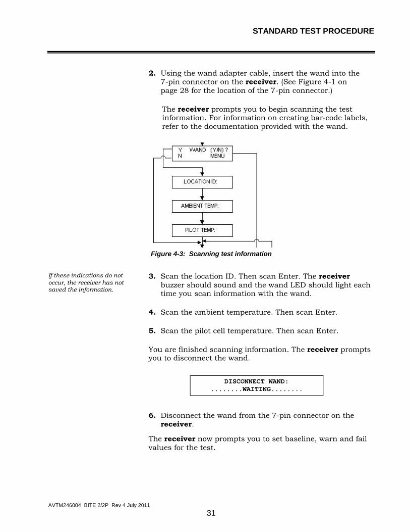
2. Using the wand adapter cable, insert the wand into the
7-pin connector on the receiver. (See Figure 4-1 on page 28 for the location of the 7-pin connector.)
The receiver prompts you to begin scanning the test information. For information on creating bar-code labels, refer to the documentation provided with the wand.
Figure 4-3: Scanning test information
If these indications do not occur, the receiver has not saved the information.
3. Scan the location ID. Then scan Enter. The receiver buzzer should sound and the wand LED should light each time you scan information with the wand.
4. Scan the ambient temperature. Then scan Enter.
5. Scan the pilot cell temperature. Then scan Enter.
You are finished scanning information. The receiver prompts you to disconnect the wand.
DISCONNECT WAND:
........WAITING........
6. Disconnect the wand from the 7-pin connector on the receiver.
The receiver now prompts you to set baseline, warn and fail values for the test.

M
AVTM246004 BITE 2/2P Rev 4 July 2011
32
Step Four: Setting Baseline, Warning and Fail Values
The BITE 2/2P now lets you set baseline, warning and fail impedance values when conducting a test. Then, after displaying the cell or strap measurements, the BITE 2/2P receiver screen will indicate PASS, FAIL or WARN and will display the measured value as a percentage of the baseline value.
After you finish wanding information, the receiver will display the following menu:
Y ENTER BASELINE? N (Y/N) MENU
If you do not want to set baseline, warn and fail values, press (for NO). The receiver screen will ask whether you want to split the strap. Go to "Step Five: Splitting the Strap below.
If you want to enter baseline, warn and fail values, press (for YES).
BASE WARN FAIL XX.XX XX% XX%
1. Use the
to scroll through the digits until the desired digit is displayed.
2. Press .
3. Repeat for each digit and the decimal point until the desired baseline, warn and fail values are displayed.

STANDARD TEST PROCEDURE
AVTM246004 BITE 2/2P Rev 4 July 2011
33
Step Five: Splitting the Strap (if needed)
After the Wand Menu and Enter Baseline menu, the receiver displays a screen that asks whether you want to split the strap.
You need to split the strap if the strap you want to measure consists of more cables or intercell connectors than the diameter of the clamp-on current sensor (CT) can handle.
Y SPLIT STRAP N (Y/N)? MENU
NOTE: Splitting a strap may not split the current equally. Verify that the current is split fairly evenly between the straps. If the current split is not even, then try to find another location where the current is more evenly split.
If You Do Not Want to Split the Strap
If you do not want to split the strap, simply press (for NO) on the receiver, which instructs the receiver not to split the strap.
You are prompted to connect the CT to the strap. Proceed to “Step Six: Connecting the Receiver and the BITE 2 or BITE 2P Transmitter to the Battery” on page 35.
If You Want to Split the Strap
If you want to split the strap:
1. Press on the receiver to enter Y (for YES).
The receiver prompts you to enter a multiplier, which is a numeric value that the receiver uses to determine the measurement of the entire strap.
UP MULTIPLIER DN >1_< ACCEPT

M
AVTM246004 BITE 2/2P Rev 4 July 2011
34
For example, suppose that the strap you want to measure consists of four cables, but you can get the standard CT around only two of them. You would need to enter a multiplier of 2.
The receiver would then multiply the reading you take by two so that the proper test results are computed for all four cables.
Pressing increases the multiplier. Pressing decreases the multiplier.
2. Press or to specify the correct multiplier.
3. When the multiplier you want to use is displayed, press
to accept the multiplier value.
Saving the settings saves the baseline, warn and fail values and the multiplier.
The receiver screen asks if you want to save settings
Y SAVE SETTING? N (Y/N) MENU
Press (for YES) or for (NO). Proceed to Step Six.

STANDARD TEST PROCEDURE
AVTM246004 BITE 2/2P Rev 4 July 2011
35
Step Six: Connecting the Receiver and the BITE 2 or BITE 2P Transmitter to the Battery
F WARNING!
To avoid electric shock, always wear rubber gloves when making connection to battery systems. Voltages to ground in excess of 270 V dc are possible.
1. The receiver screen prompts you to connect the CT.
CONNECT CT! XX.X
RIPPLE CURRENT
2. Connect the plug of the CT to the 4-pin connector on the receiver. Figure 4-4 shows the location of the 4-pin connector.
POWER ON Switch
ENTER Key
7-Pin Connector
4-Pin Connector
Potential Probe
3-Pin Connector
LCD
TRIGGER
UP and DOWN ARROW Keys
Figure 4-4: Receiver controls, connectors, and indicators

M
AVTM246004 BITE 2/2P Rev 4 July 2011
36
If you are splitting the strap, keep in mind the multiplier you specified. When the CT is connected, the receiver displays a measurement of the system ripple current.
3. Position the clamp-on end of the CT around a convenient intertier or intercell connection on the battery so that the current you are going to measure will be within the loop created by the current source leads from the transmitter and the battery string.
NOTE: Loads, parallel strings, and charging equipment can create parallel paths for the measurement current. Therefore, place the standard 2 in. CT at a location that verifies the source measurement current for the cells under test. Do not place the CT around the current source lead. This may not represent the current flowing through the battery string.
4. Pull the receiver trigger to advance the receiver and store
the ripple-current reading.
5. Next, the receiver screen prompts you to begin connecting
the BITE 2/2P transmitter to the battery.
CONNECT & POWER TRANSMITTER: XX.X
To ac powerSource leads fromtransmitter connectedto terminal plate
to terminal platetransmitter connectedSource leads from
RedBlack
Figure 4-5: BITE 2/2P transmitter connected to the battery
STANDARD TEST PROCEDURE
AVTM246004 BITE 2/2P Rev 4 July 2011
37
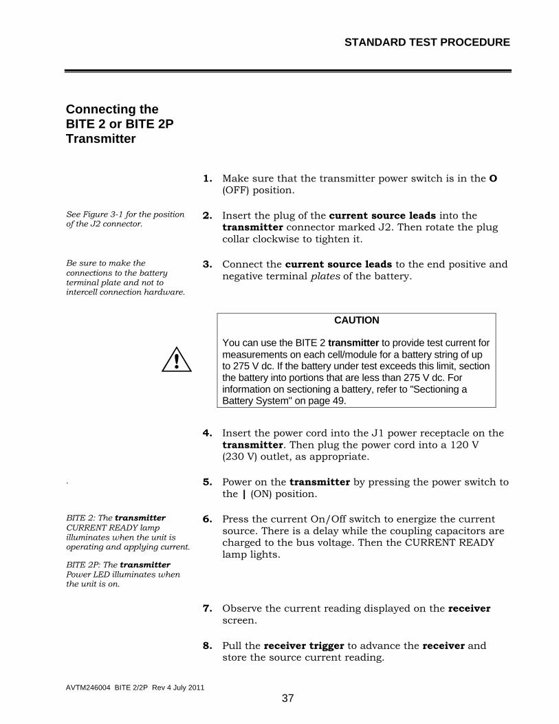
Connecting the BITE 2 or BITE 2P Transmitter
1. Make sure that the transmitter power switch is in the O (OFF) position.
See Figure 3-1 for the position of the J2 connector.
2. Insert the plug of the current source leads into the transmitter connector marked J2. Then rotate the plug collar clockwise to tighten it.
Be sure to make the connections to the battery terminal plate and not to intercell connection hardware.
3. Connect the current source leads to the end positive and negative terminal plates of the battery.
G CAUTION
You can use the BITE 2 transmitter to provide test current for measurements on each cell/module for a battery string of up to 275 V dc. If the battery under test exceeds this limit, section the battery into portions that are less than 275 V dc. For information on sectioning a battery, refer to "Sectioning a Battery System" on page 49.
4. Insert the power cord into the J1 power receptacle on the
transmitter. Then plug the power cord into a 120 V (230 V) outlet, as appropriate.
. 5. Power on the transmitter by pressing the power switch to the | (ON) position.
BITE 2: The transmitter CURRENT READY lamp illuminates when the unit is operating and applying current.
BITE 2P: The transmitter Power LED illuminates when the unit is on.
6. Press the current On/Off switch to energize the current source. There is a delay while the coupling capacitors are charged to the bus voltage. Then the CURRENT READY lamp lights.
7. Observe the current reading displayed on the receiver
screen.
8. Pull the receiver trigger to advance the receiver and
store the source current reading.

M
AVTM246004 BITE 2/2P Rev 4 July 2011
38
The receiver displays the first test screen, which prompts you to measure the first cell. Proceed to “Step Seven: Measuring the Cell and the Strap.”
Operating Note
If there are less than 3 A flowing within the string of cells selected, the receiver displays a message indicating low current (Lo_A). This ensures proper current magnitude for accurate measurement since the total current includes both current from the BITE 2/2P and any ac ripple current produced by the battery charger. If significant ripple current is present and out of phase with the applied source current, a low current condition may occur. If this happens, first turn off the BITE 2/2P transmitter, then reverse the polarity of the current source leads to bring the two currents in phase. For the majority of applications, this will not present any difficulty. (Refer to Chapter 5 for more information.)
Step Seven: Measuring the Cell and the Strap
G CAUTION
Do not exceed 25 V dc, the maximum voltage allowed between the receiver and the potential probe.
After the transmitter is connected to the battery and is powered on, the receiver displays the first test screen.
CELL VOLTS mΩ
001 XX.XX XX.XX T01
The digits displayed in the upper left corner of the screen (001) indicate that you are ready to test the first cell. The digits in the lower left corner indicate the number of the active test (for example, T01 for test one, T02 for test two, and so on).
To begin testing the first cell in the string:
The twisting action of the probe tips as the handle is pushed down cleans the point of contact and provides a better test connection. See Figure 4-6.
1. Position the receiver on the positive terminal and the potential probe on the negative terminal of the cell/jar, and then press down.

STANDARD TEST PROCEDURE
AVTM246004 BITE 2/2P Rev 4 July 2011
39
NOTE: The reason the receiver should be positioned on the positive terminal is to obtain a positive float voltage of the cell. Then a cell that has gone into “cell reversal” becomes very evident when it displays a negative float voltage.
connected to negativefrom TransmitterCurrent Source Lead
RedBlack
terminal plate
Current Source Leadfrom Transmitterconnected to positiveterminal plate
Figure 4-6: Receiver and potential probe positioned
on top of battery cell terminals
2. View the cell terminal voltage and ac impedance values that are displayed on the receiver screen.
A sample screen is shown below.
CELL VOLTS mΩ
001 13.43 23.33 T01
The measurements are stored in the receiver.
3. When the voltage and impedance values displayed on the screen stabilize, pull the trigger on the receiver to store the reading.
If you have entered baseline, warn and fail values, the screen will display either PASS, WARN or FAIL and a percentage of baseline.
001 T01 PASS XX%

M
AVTM246004 BITE 2/2P Rev 4 July 2011
40
If you do not want to test the strap, pull the trigger and go directly to Step Eight.
The receiver LCD now displays the word STRAP, which prompts you to test the strap that is associated with the cell you just tested.
CELL VOLTS mΩ
001 13.43 23.33 T01 STRAP 0.112
4. Position the receiver and potential probe on top of the battery strap terminals, and then press the probes down. See the sample placement shown in Figure 4-7.
Red Black
Current Source Lead from Transmitter connected to terminal positive plate
Current Source Lead from Transmitter connected to terminal negative plate
Figure 4-7: Receiver and potential probe positioned
on top of battery strap terminals

STANDARD TEST PROCEDURE
AVTM246004 BITE 2/2P Rev 4 July 2011
41
5. When the strap value displayed on the screen stabilizes, pull the trigger on the receiver to store the reading.
The measurements are stored in the receiver.
The receiver now displays the digits 002 in the top left corner of the test screen. This means that you are ready to test cell #2.
If you are testing a sectioned battery string and want to test the next section, refer to the following subsection, “Measuring the Next Section of a Sectioned Battery String,” for the appropriate procedures.
6. Continue to measure the other cells and straps in the string.
7. After the last cell, the receiver expects a strap result. Short the receiver and potential probe together and pull the trigger. This saves the last cell’s data or else it will be lost.
8. When you are finished measuring all the cells and straps, press on the receiver to complete the test.
The receiver prompts you to confirm that the test is complete.
Y TEST COMPLETE N (Y/N)? MENU
Review the test information that is stored in the receiver. You can scroll through the results and, if needed, retest individual cells and straps. Refer to "Reviewing a Test” on page 43.
9. Press on the receiver to enter Y (for YES).
The receiver prompts you again to confirm that the test is complete.
Y ARE YOU SURE N (Y/N)? MENU
10. Press on the receiver to enter Y (for YES).
The receiver displays a screen to indicate that the test is complete.
DONE!
For instructions on what to do following the test, see "Step Eight: What to Do When the Test Is Complete” on page 43.

M
AVTM246004 BITE 2/2P Rev 4 July 2011
42
Measuring the Next Section of a Sectioned Battery String
If you have finished testing the first section of a sectioned battery string and want to measure the next section:
1. Press the Current ON/OFF switch on the BITE 2/2P transmitter.
This blocks the current from being applied to the battery while the transmitter powers down.
2. Connect the current source leads to the next battery section.
NOTE: If you are interrupted and need to leave the site unexpectedly, simply shut down the receiver and transmitter. The receiver will “remember” where you left off when you return to finish the test.
F WARNING
Do not remove the BITE 2/2P transmitter current source leads from the battery until the BITE 2/2P transmitter is powered off. Always disconnect the current source leads from the battery before removing them from the J2 connector on the transmitter. Do not leave the BITE 2/2P connected to the battery when not in use.
3. Press the Current On/Off switch on the BITE 2/2P transmitter.
After the CURRENT READY light illuminates, the current is applied to the battery and you can continue testing.
Test the section. Repeat the procedure as needed, depending on the number of sections in the battery string.

STANDARD TEST PROCEDURE
AVTM246004 BITE 2/2P Rev 4 July 2011
43
Step Eight: What to Do When the Test Is Complete
You can perform the following operations after a test is complete:
1. Export test results to a PC. You can then use the PC to view or print the test results. (Refer to Chapter 6.)
2. Print test results on the BITE 2P transmitter printer.
3. Delete the test information from the receiver.
4. Start a new test. (Return to "Step One: Prepare for Testing" page 27.)
5. Power down and disconnect the transmitter. You will need to do this if you are finished using the BITE 2/2P for this testing session. (See "Powering Down and Disconnecting the BITE 2/2P" on page 45).
Reviewing a Test
At any time while you are performing a test, you can review the results of the active test that are already stored in the receiver.
1. To review the current test, press on the receiver to scroll back through the active test screens.
2. Press to scroll forward through the active test screens.
You may print the active test results on the BITE 2P transmitter printer for review. Please note that there are no statistics or bar graphs printed for the active test. See "Printing an Active Test to Review the Data (BITE 2P)" on page 44.

M
AVTM246004 BITE 2/2P Rev 4 July 2011
44
Retesting Cells and Straps
You cannot review a test after it has been completed. (Refer to "Step Seven: Measuring the Cell and the Strap," #'s 6,7, and 8, for a description of completing a test.)
If needed, you can retest any of the cells or straps in the current test.
1. Navigate through the test screens until information about the cell or strap you want to retest is displayed.
2. Pull the trigger.
The receiver enters into test mode.
001 XX.XX XX.XX T01
3. Position the receiver and potential probe on top of the battery cell terminals, and then press down.
4. When the voltage and impedance values displayed on the LCD stabilize, pull the trigger to store the readings.
See the sample placement shown in Figure 4-7 on page 40.
5. When the strap values displayed on the screen stabilize, pull the trigger to store the reading.
NOTE: Both measurements must be taken.
6. To return to testing, scroll forward to the next cell.
7. To retest another cell/strap, repeat steps 1-5.
Printing an Active Test to Review the Data (BITE 2P)
To print the test data of the string for which you are taking measurements, disconnect the potential probe and connect the printer cable to J3. The LCD will display the following screen.
STANDARD TEST PROCEDURE
AVTM246004 BITE 2/2P Rev 4 July 2011
45
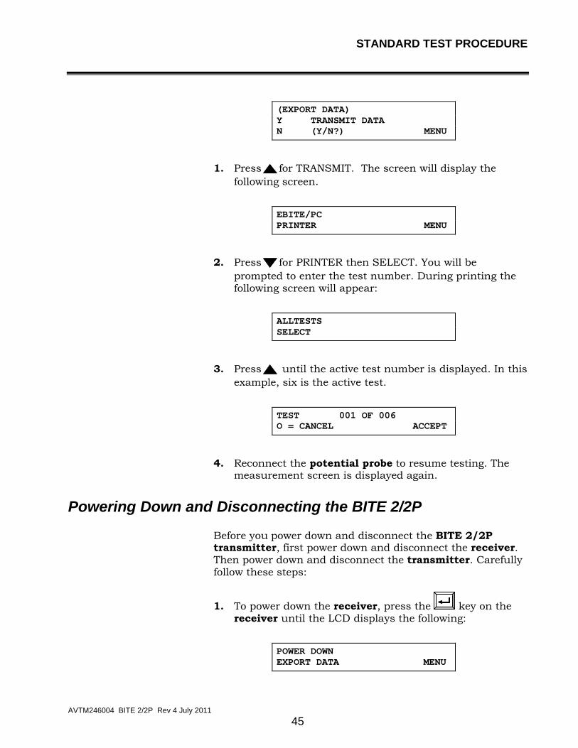
(EXPORT DATA) Y TRANSMIT DATA N (Y/N?) MENU
1. Press for TRANSMIT. The screen will display the following screen.
EBITE/PC PRINTER MENU
2. Press for PRINTER then SELECT. You will be prompted to enter the test number. During printing the following screen will appear:
ALLTESTS SELECT
3. Press until the active test number is displayed. In this example, six is the active test.
TEST 001 OF 006 O = CANCEL ACCEPT
4. Reconnect the potential probe to resume testing. The measurement screen is displayed again.
Powering Down and Disconnecting the BITE 2/2P
Before you power down and disconnect the BITE 2/2P transmitter, first power down and disconnect the receiver. Then power down and disconnect the transmitter. Carefully follow these steps:
1. To power down the receiver, press the
key on the
receiver until the LCD displays the following:
POWER DOWN EXPORT DATA MENU

M
AVTM246004 BITE 2/2P Rev 4 July 2011
46
2. Press on the receiver to choose POWER DOWN.
The receiver prompts you to confirm your decision.
Y ARE YOU SURE? N (Y/N)? MENU
3. Press on the receiver to enter Y (YES). The receiver powers down.
4. Disconnect the CT from the battery and the receiver.
You can now power down the transmitter.
5. To power down the BITE 2/2P transmitter, press the Current ON/OFF switch to disconnect the current source. Then press the transmitter power switch to the O (OFF) position.
F WARNING
Do not remove the BITE 2/2P transmitter current source leads from the battery until the BITE 2/2P transmitter is powered down. Always disconnect the current source leads from the battery before removing them from the J2 connector on the transmitter.
6. Remove the current source leads from the battery.
7. Remove the current source leads from the J2 connector on the transmitter.
Remember to recharge the receiver battery. Refer to "Charging the Receiver" on page 74 for detailed procedures.
8. Unplug the power cable and then disconnect it from the J1 receptacle on the transmitter.
G CAUTION
Do not leave the BITE 2/2P connected to the battery when not in use.

M
AVTM246004 BITE 2/2P Rev 4 July 2011
47
5
MODIFIED PROCEDURES FOR SPECIAL CONDITIONS
Overview
This chapter explains how to perform alternative test procedures, including reversing the current source leads and sectioning battery systems to correct high or low current situations.
This chapter also describes optional equipment that can be used with the BITE 2 and BITE 2P test instruments.
Reversing the Current Source Leads
If the transmitter displays a high or low current message, you need to modify the test procedure. See the following subsections for alternative test procedures.
Figure 5-1 shows a battery system with a single string of cells. If a high or low current message is displayed on the receiver after you connect the current source leads to a similar battery configuration, try reversing the polarity of the current source leads. Doing so shifts the test current by 180 degrees and offsets the effect of the system ripple current in the receiver. This helps ensure sufficient test current in the section of the battery string to enable computation of cell impedance or strap resistance.

M
AVTM246004 BITE 2/2P Rev 4 July 2011
48
J2
From transmitter (current source leads)
Figure 5-1: Reversing the current source leads on a single string of cells
when a high or low current message is displayed.
Verifying the Source Current
A low current indication on the transmitter’s analog or digital meter can be caused by high resistance in the cell string. To verify whether the magnitude of the source current is within the required limits (3-15 A):
This temporarily “disconnects” the transmitter and blocks the current from going to the battery.
1. Press the Current switch on the BITE 2/2P transmitter to the ( (OFF) position.
2. Disconnect the current source leads from the battery.
3. Connect the current source lead clips together and restart current flow by pressing the BITE 2/2P transmitter Current On/Off switch to the (ON) position.

MODIFIED PROCEDURES FOR SPECIAL CONDITIONS
AVTM246004 BITE 2/2P Rev 4 July 2011
49
F WARNING
Do not remove the BITE 2/2P transmitter current source leads from the battery until the transmitter is powered off. Always disconnect the current source leads from the battery before removing them from the J2 connector on the transmitter. Do not leave the BITE 2/2P connected to the battery when not in use.
If the LCD displays "Lo_A", refer to page 88 under "Maintenance and Troubleshooting."
The wire for the current source lead set extends from only one side of each pair of jaws.
Section the battery system by connecting the current source leads across individual sections of the string to isolate high-resistance or open cells and straps. (See "Sectioning a Battery System” below for the correct procedures.)
Sectioning a Battery System
To test certain battery systems with the BITE 2/2P, you must measure individual sections, one at a time. Examples are included in the following subsections.
Sectioning a Battery System Greater than 275 Volts
The nonpolarized coupling capacitor in the BITE 2/2P current source is limited to 275 V. This restricts the current source applied across battery systems of 275 V dc and higher.
If the battery system to be tested is greater than 275 V, you must test the system in sections that are 275 V or less. It is recommended that you section the battery in equally-sized sections.
Figure 5-2 shows a 600 V dc UPS system in which the source current leads are connected across a 200 V section of the battery string.

M
AVTM246004 BITE 2/2P Rev 4 July 2011
50
B
Not to exceed 250 V dc
J2
From transmitter (current source leads)
A
Figure 5-2: Sectioning a battery system greater than 275 V
The potential between the current source leads (red at A and black B) in Figure 5-1 cannot exceed 275 V. To section the string:
1. Place the current source leads (at points A and B) in the string so that the potential does not exceed 275 V.
2. Test the cells located between connections A and B.
3. When you are finished testing the cells, press the Current switch on the transmitter to the O (OFF) position.
NOTE: If you have to move the transmitter to test the next section, you may need to power down and disconnect the transmitter. (See "Powering Down and Disconnecting the BITE 2/2P" on page 45.)
4. Remove the current source leads from the battery. Then move them to the next section to be tested (not to exceed 275 V).

MODIFIED PROCEDURES FOR SPECIAL CONDITIONS
AVTM246004 BITE 2/2P Rev 4 July 2011
51
F WARNING
Do not remove the BITE 2/2P transmitter current source leads from the battery until the BITE 2/2P transmitter current is de-energized. Always disconnect the current source leads from the battery before removing them from the J2 connector on the transmitter. Do not leave the BITE 2/2P connected to the battery when not in use.
5. Press the Current On/Off switch.
The current is applied to the battery and you can continue testing.
6. Test the section.
Repeat the procedure, as needed, depending on the number of sections in the battery string.
Sectioning a Battery System with Parallel Strings
Figure 5-3 shows how to start sectioning a battery system with parallel strings of cells. To test this string, you must section the system to supply the proper level of test current needed to stimulate the cell impedance or strap resistance measurements.
You may see other ripple current influences as noted in the single string of cells (see Figure 5-1) and you may have to interchange the polarity of the current source lead clips.
F
WARNING
Do not remove the current source leads from the battery until the transmitter is turned off. Always remove the leads at the battery connection before removing them from the J2 connection on the transmitter.

M
AVTM246004 BITE 2/2P Rev 4 July 2011
52
125 V dc
40 V dc section (example)
J2
From transmitter (current source leads)
Figure 5-3: Sectioning a parallel string of cells
Sectioning High-Voltage UPS Batteries
Some UPS systems with voltages up to 600 V dc are designed with parallel strings of cells. To test one of these systems, positions the current source leads accordingly to satisfy both the test current and the voltage limit of the BITE 2/2P.
Refer to the procedure explained in the preceding subsection, "Sectioning a Battery System Greater than 275 Volts" In addition consider the string impedance with reference to the remaining parallel string influences. Ensure that the majority of the current flows through the cells under test and not through parallel influences. (See Figure 5-2)

MODIFIED PROCEDURES FOR SPECIAL CONDITIONS
AVTM246004 BITE 2/2P Rev 4 July 2011
53
Sectioning Noisy UPS Systems
The BITE 2/2P source current may be affected by the noise generated by the switching power supply or the inverter. In this situation, test only a few cells at a time. See Figure 5-2 and refer to the procedure explained earlier in the subsection, “Sectioning a Battery System Greater than 275 Volts."
An alternative, although not normally recommended, is to not apply a test signal from the transmitter, but to use the noise in the system to induce the signal that is measured. Impedance will be calculated based on the current signal as an artifact of the noisy charger/rectifier. The receiver will not take measurements if the total current is less than 3 A or more than 15 A to maintain data reliability.

M
AVTM246004 BITE 2/2P Rev 4 July 2011
54
M

M
AVTM246004 BITE 2/2P Rev 4 July 2011
55
6
TRANSFERRING, PRINTING, AND DELETING TEST RESULTS
Overview
This chapter explains how to:
• Transfer test results from the receiver to a personal computer (PC)
• Print test results from the receiver to the BITE 2P transmitter
• Delete test results from the receiver
When a test is completed using the BITE 2/2P, the results are automatically stored in the receiver.
If needed the test results can be exported to a personal computer (PC) where it can then be viewed or printed.
If the PC has the appropriate software, the test information can be imported into standard spreadsheet programs for further analysis.
Test results can also be printed from the receiver to the BITE 2P transmitter printer.
Test results that are no longer needed may also be deleted from the receiver.
The following subsections contain the appropriate procedures.

M
AVTM246004 BITE 2/2P Rev 4 July 2011
56
Exporting Test Results from the Receiver to a PC
NOTE: The device receiving the data must be ready before transmitting the data.
The results of a test can be exported from the receiver directly to the PC.
1. Run the software on the PC that you are using to import the data.
If needed, refer to the instruction manual that came with the software. Megger has shipped with the BITE 2/2P a software program called AVO®Link. Please refer to the Addendum to this manual for detailed instructions on AVO®Link.
2. Press the receiver Power On switch to energize the receiver.
If you insert the RS-232 communication cable into the receiver before powering on the receiver, the Transmit Data Menu is automatically displayed in place of Menu 1.
3. Press on the receiver to access Menu 1.
POWER DOWN EXPORT DATA MENU
Press on the Receiver to select Y and skip steps 4 and 5 below.
Y TRANSMIT DATA N (Y/N) MENU
Y Transmit Data N (Y/N) Menu

TRANSFERRING, PRINTING, AND DELETING TEST RESULTS
AVTM246004 BITE 2/2P Rev 4 July 2011
57
Figure 6-1: Exporting data to a PC
If the RS-232 communication cable is not connected, the receiver displays a message instructing you to connect it.
4. Connect the plug of the RS-232 communication cable/printer (Cat. No. 35340) to the 7-pin connector on the receiver. Then insert the pin end of the communication cable into the com port on the PC.
5. Press on the receiver to select EXPORT DATA.
The receiver prompts you to select EBITE/PC or printer.
EBITE/PC PRINTER MENU
6. Press on the receiver to select PC.
A screen on the receiver tells you to wait as the test results are transferred.
When the transfer is complete, the receiver prompts you to choose POWER DOWN or EXPORT DATA.
POWER DOWN EXPORT DATA MENU
7. Disconnect the RS-232 communication cable from both the receiver and the PC.

M
AVTM246004 BITE 2/2P Rev 4 July 2011
58
8. Turn off the power to the transmitter and receiver. (See "Powering Down and Disconnecting the BITE 2/2P" on page 45.
Printing Test Results in the BITE 2P Transmitter Printer
To print test results on the built-in printer of the BITE 2P transmitter, connect the printer cable to the 7-pin connector on the receiver and to J3 on the BITE 2P transmitter. Follow the menus on the receiver to select the tests you wish to print.
Figure 6-2: Printing test results
TRANSFERRING, PRINTING, AND DELETING TEST RESULTS
AVTM246004 BITE 2/2P Rev 4 July 2011
59
Deleting Test Results from the Receiver
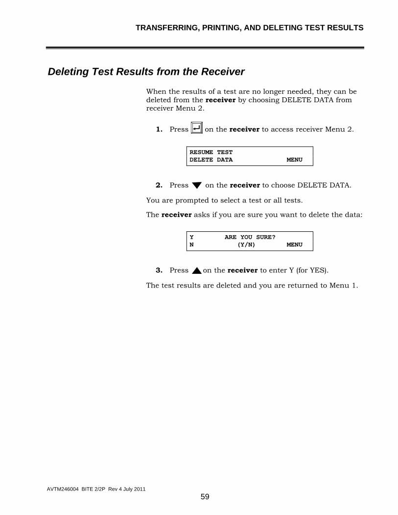
When the results of a test are no longer needed, they can be deleted from the receiver by choosing DELETE DATA from receiver Menu 2.
1. Press on the receiver to access receiver Menu 2.
RESUME TEST DELETE DATA MENU
2. Press on the receiver to choose DELETE DATA.
You are prompted to select a test or all tests.
The receiver asks if you are sure you want to delete the data:
Y ARE YOU SURE? N (Y/N) MENU
3. Press on the receiver to enter Y (for YES).
The test results are deleted and you are returned to Menu 1.

M
AVTM246004 BITE 2/2P Rev 4 July 2011
60
Figure 6-3: Deleting test results from the Receiver

M
AVTM246004 BITE 2/2P Rev 4 July 2011
61
7
INTERPRETING TEST RESULTS
Overview
This chapter discusses various factors to consider when interpreting results of tests obtained with the BITE 2/BITE 2P.
Megger maintains a database of impedance values. Megger will provide approximate baseline values if specific information is received from the user. The list of required information needed from the user is found on our website, www.megger.com.
Impedance measurements with the BITE 2/2P should be made part of a battery maintenance program with readings taken and recorded semiannually for flooded lead-acid and nickel-cadmium cells and quarterly for VRLA.
Increases in impedance are caused by numerous factors. Some of the failure modes that can be detected by impedance are:
• plate sulphation
• dry-out
• soft shorts (dendritic shorts)
• hard shorts (due to sediment build-up or paste lumps)
• intercell and intertier connections (due to loose hardware or corrosion)
• internal corrosion
However, there are other factors that can change the impedance value of a cell. Impedance shifts can be caused by:
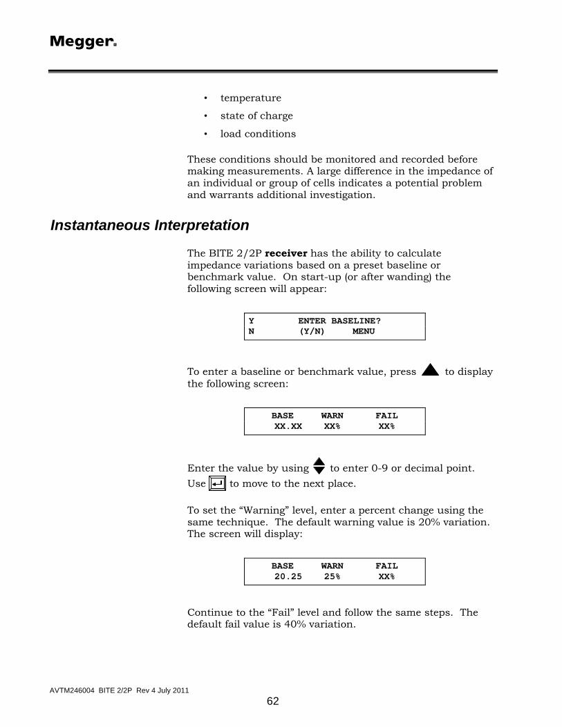
M
AVTM246004 BITE 2/2P Rev 4 July 2011
62
• temperature
• state of charge
• load conditions
These conditions should be monitored and recorded before making measurements. A large difference in the impedance of an individual or group of cells indicates a potential problem and warrants additional investigation.
Instantaneous Interpretation
The BITE 2/2P receiver has the ability to calculate impedance variations based on a preset baseline or benchmark value. On start-up (or after wanding) the following screen will appear:
Y ENTER BASELINE? N (Y/N) MENU
To enter a baseline or benchmark value, press to display the following screen:
BASE WARN FAIL XX.XX XX% XX%
Enter the value by using
to enter 0-9 or decimal point. Use to move to the next place.
To set the “Warning” level, enter a percent change using the same technique. The default warning value is 20% variation. The screen will display:
BASE WARN FAIL 20.25 25% XX%
Continue to the “Fail” level and follow the same steps. The default fail value is 40% variation.

INTERPRETING TEST RESULTS
AVTM246004 BITE 2/2P Rev 4 July 2011
63
BASE WARN FAIL 20.25 25% 40%
After each cell/strap measurement, the receiver displays the percent variation and the cell status. Also, the receiver will remember the last values entered since they were saved when they were entered.
Short-Term Interpretation
Impedance readings for individual cells can be used in the short term to compare each cell with the average impedance reading for the entire battery. Cells with the deviations listed below require further investigation:
• Flooded lead-acid cells of more than 15% deviation from the string average
• Valve-regulated, lead-acid cell of more than 35% deviation from the string average
• Nickel-cadmium cells of more than 50% deviation from the string average and may be exhibiting “memory.”
The deviations are shown in the bar graph accompanying the printout of a closed test.
Additional investigation of cells exhibiting the above deviations is recommended (cell temperature and specific gravity, if appropriate) and perhaps a load cycle test. Megger recommends that you perform a complete analysis before replacing cells due solely to high or increasing impedance values.
Long-Term Interpretation
Impedance readings for the entire battery can be used in the long term to determine the need for replacement. Battery cell impedance values should be recorded and compared to previous readings to determine the position of the cell on the curve of impedance versus cell life. Generally speaking, cells with the following variations require immediate attention:

M
AVTM246004 BITE 2/2P Rev 4 July 2011
64
• Flooded lead-acid cells having variations (from
baseline) greater than 20%
• Valve-regulated, lead-acid cell having variations greater than 50%
• Nickel-cadmium cells having variations greater than 100%.
A sample curve for a generic valve-regulated, lead-acid cell is shown in Figure 7-1. Curves may differ for other manufacturers and battery chemistries, such as nickel-cadmium.
The initial decrease in impedance is due to the completion of the formation process, i.e., the conversion to active plate material.
Impedance vs. Expected Battery LifeVRLA Cells
-30
-20
-10
0
10
20
30
40
50
60
0 20 40 60 80 100 120
% of Expected Battery Life
% Im
ped
ance
Ch
ang
e fr
om
Bas
elin
e
WEAK NORMAL
ABNORMAL
Figure 7-1: Generic curve of impedance vs. cell life
Temperature Corrections
The internal impedance of a cell is inversely influenced by temperature. In addition, the degree of influence depends on battery type and length of exposure to the present ambient temperature.
Flooded battery types have a significantly more thermal mass and are slower to react to changing ambient temperatures than VRLA cells. The actual internal cell temperature can be measured by inserting a thermometer into the flooded cell via a fill tube or vent cap to determine the temperature present during impedance testing. Measure the temperature of VRLA cells at the negative terminal.

INTERPRETING TEST RESULTS
AVTM246004 BITE 2/2P Rev 4 July 2011
65
NOTE: Please note the placements of HVAC systems as they can have a significant effect on the temperatures of the cells in the battery. For example, cell on the top tier of a three-tier rack may have higher temperatures than the cells on the bottom tier.
NOTE: Middle cells in three-cell or four-cell trays of Valve-regulated, lead-acid batteries may have a higher temperature due to the inability to remove heat as well as the outside cells.
A suggested correction factor for impedance values of flooded lead-acid cells is shown below:
Zb @ 77 ° F = 0.088 (Zm)
(T + 30) -0.520
Zb = corrected battery impedance to 77 ° F
Zm = measured impedance value
T = measured temperature value in °F
Contact Megger at 610-676-8500.
Valve-regulated, lead-acid cells may differ among battery vendors and electrolyte types. Gel style cells have a different temperature response curve than the starved-electrolyte (AGM) types. If temperature correction is required, contact the battery manufacturer for these data.

M
AVTM246004 BITE 2/2P Rev 4 July 2011
66
M

M
AVTM246004 BITE 2/2P Rev 4 July 2011
67
8
SETTING OPTIONS
Overview
You can change these default options to optimize the BITE 2 and BITE 2P functions for your use.
This chapter explains how to set options that control the operation of the BITE2/2P receiver.
The BITE 2/2P receiver is shipped with certain options set, including:
• Turning the backlight on and off so that the receiver screen does or does not light up when the instrument is powered on
• Adjusting the screen contrast
• Selecting the language in which the receiver displays information (English, Français, Deutsch, Español, Português)
• Setting the date and time
• Setting the line frequency to 50 or 60Hz

M
AVTM246004 BITE 2/2P Rev 4 July 2011
68
Turning the Receiver Backlight ON and OFF
To turn the receiver backlight on and off so that the receiver screen does or does not light when the instrument is powered on:
1. Press to access the following receiver Menu.
BACKLIGHT CONTRAST MENU
2. Press to select Backlighting.
You are prompted to turn the backlight on or off.
ON BACKLIGHT OFF ON/OFF? MENU
3. Press to turn the backlight on. Or press to turn the backlight off.
The receiver backlight is set as you specified.
Adjusting the Receiver Screen Contrast
To adjust the contrast of the receiver screen:
1. Press to access the receiver Menu 3.
BACKLIGHT CONTRAST MENU
2. Press to select CONTRAST.
You are prompted to turn the contrast up or down.
UP CONTRAST DN DONE

MAINTENANCE & TROUBLESHOOTING
AVTM246004 BITE 2/2P Rev 4 July 2011
69
3. Press to turn the contrast up. Or press to turn the contrast down. Select DONE when the display is set as desired.
Selecting the Receiver Language
The receiver is programmed to display information in a number of languages. English is the default; however, you can easily select another language.
1. Press to access the receiver Menu 4.
LANGUAGE SETTIME MENU
2. Press to select LANGUAGE.
The first two language choices are displayed.
ENGLISH FRANCAIS NEXT
Press
or
to select one of the languages displayed. Or
press
to view additional available languages.
Once you make a selection, the receiver displays screen information using the language you chose.
Setting the Receiver Clock
To set the date and time in the receiver clock:
1. Press to access the receiver Menu.
LANGUAGE SETTIME MENU
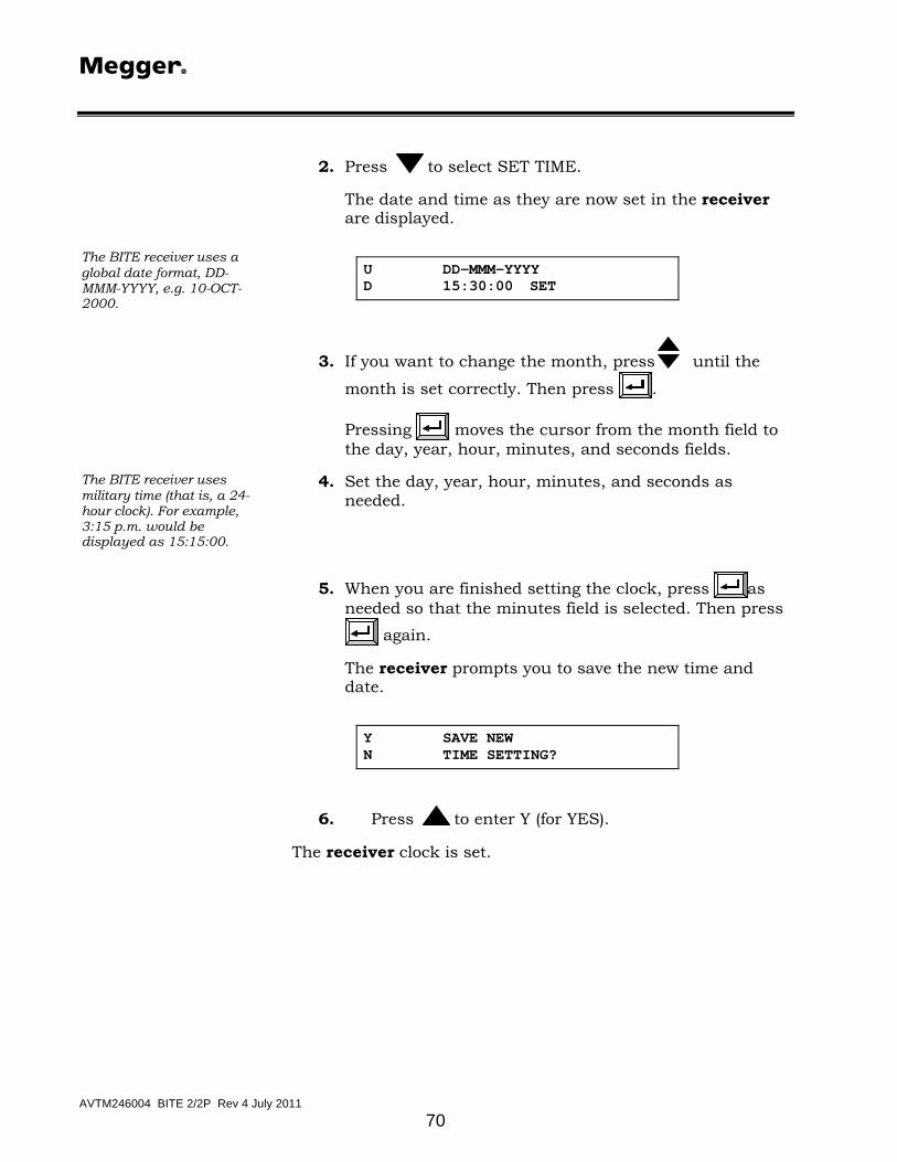
M
AVTM246004 BITE 2/2P Rev 4 July 2011
70
2. Press to select SET TIME.
The date and time as they are now set in the receiver are displayed.
The BITE receiver uses a global date format, DD-MMM-YYYY, e.g. 10-OCT-2000.
U DD-MMM-YYYY D 15:30:00 SET
3. If you want to change the month, press
until the
month is set correctly. Then press .
Pressing moves the cursor from the month field to the day, year, hour, minutes, and seconds fields.
The BITE receiver uses military time (that is, a 24-hour clock). For example, 3:15 p.m. would be displayed as 15:15:00.
4. Set the day, year, hour, minutes, and seconds as needed.
5. When you are finished setting the clock, press as
needed so that the minutes field is selected. Then press again.
The receiver prompts you to save the new time and date.
Y SAVE NEW N TIME SETTING?
6. Press to enter Y (for YES).
The receiver clock is set.

MAINTENANCE & TROUBLESHOOTING
AVTM246004 BITE 2/2P Rev 4 July 2011
71
Selecting the Line Frequency
The frequency setting in the receiver must be the same as the line frequency at the outlet. To set the line frequency:
1. Press until the following screen appears.
2. Use
to select the correct frequency.
3. Press MENU to exit the line frequency set-up.
* 60 Hz LINE FREQ 50 Hz MENU

M
AVTM246004 BITE 2/2P Rev 4 July 2011
72
M

M
AVTM246004 BITE 2/2P Rev 4 July 2011
73
9
MAINTENANCE AND TROUBLESHOOTING
Overview
This chapter explains:
• How to maintain the BITE 2/2P so that it remains in good operating condition
• How to interpret error messages
• What to do if repairs are needed
NOTE: Before performing maintenance on the BITE 2 or BITE 2P, please read, understand, and observe all safety precautions as indicated in Chapter 2, “Safety”. Maintenance should be performed only by qualified personnel familiar with the hazards involved with line-operated test equipment.
F
WARNING
The BITE 2/2P transmitters contain large high-voltage capacitors. During operation these capacitors could be charged up to about 300 V dc. Normally these capacitors are automatically discharged when the instrument is switched off. However, under certain fault conditions, these capacitors may be left charged. Always use a voltmeter to check the state of the charge and wear rubber gloves as necessary when touching the capacitors and the circuits connected to them.

M
AVTM246004 BITE 2/2P Rev 4 July 2011
74
Cleaning and Inspecting the BITE 2 and BITE 2P
F WARNING
Always power off and disconnect the BITE 2/2P transmitter before cleaning it.
Since the BITE 2/2P are used in corrosive environments, all components and test leads should be cleaned periodically (approximately every six months) with a mild detergent and a soft cloth.
G CAUTION
Do not immerse the any components of the BITE 2/2P in water or allow moisture to enter the case.
Inspect measuring and current source leads for corrosion and wear.
Charging the Receiver
The BITE receiver is powered by a 4.8 V rechargeable Ni-Cd battery pack. The built-in Ni-Cd battery charger is designed to recharge the battery pack in approximately one hour.
To recharge the receiver battery pack:
Refer to "Powering Down and Disconnecting the BITE 2/2P" on page 45.
1. Turn off the receiver.
2. Insert the ac power cord into the transmitter ac receptacle at J1. Plug the power cord into an outlet.
Refer to Figure 3-1 and Figure 3-2 for the location of the receiver charger on the BITE 2 and BITE 2P transmitters.
3. Connect the charger 3-pin input connector to J4 on the transmitter at the charger panel.
Refer to Figure 4-4 on page 35 for the location of the 3-PIN connector.
4. Connect the charger 3-pin output connector to the receiver 3-pin mating connector.

MAINTENANCE & TROUBLESHOOTING
AVTM246004 BITE 2/2P Rev 4 July 2011
75
5. Press the Charger On/Off switch.
The yellow LED on the panel turns on to indicate that charging is underway. The yellow light flashes when charging is complete.
F WARNING
If the yellow light does not turn on after approximately 10 seconds, there may be a serious electrical problem that should be addressed by qualified personnel.
NOTE: The receiver cannot be operated while it is being charged.
6. Unplug the ac power cord from the outlet and disconnect the charger from the receiver.
Replacing Batteries in the Receiver
There are two batteries in the receiver: a battery pack of four 1.2 V AA Ni-Cd batteries and an RTC battery. Megger recommends that you use the exact type of batteries for replacement since they match the corresponding charger characteristics.
NOTE: All data will be lost when the RTC battery is replaced. The receiver may have to be recalibrated, too.
To replace the receiver battery pack of four 1.2 V AA Ni-Cd:
Refer to “Powering Down and Disconnecting the BITE 2/2P”on page 45.
1. Turn off the receiver.
2. Disconnect all cables from the receiver.
F WARNING
Be sure to power down the receiver and disconnect all cables before disassembling the receiver to replace the battery pack. Do not connect the charger to the receiver while replacing batteries.
3. Lay the receiver on a flat surface with the display screen face down. Using a Phillips head screwdriver, remove the eight screws fastening the back cover and probe housing.

M
AVTM246004 BITE 2/2P Rev 4 July 2011
76
4. Carefully remove the probe housing. Remove the back cover.
G CAUTION
Do not disturb the wrist strap, trigger assembly, or wiring harness.
5. Locate the battery pack at the base of the receiver. Unplug the battery pack from the 5-PIN connector of the receiver printed circuit board
Dispose of the Ni-Cd battery pack in an environmentally safe way.
6. Install the replacement battery pack (part number 30654).
Be sure to align the replacement battery pack connector with the keyed mating connector on the printed circuit board.
7. Reassemble the receiver by placing the back cover over the printed circuit board.Ensure that the two connector-mounting plates are aligned with the channels inside the back cover.
8. Snap the back cover into place, and then fasten it using the six Phillips head screws.
9. Snap the probe housing into place, and then fasten it using the two Phillips head screws.
F WARNING
Make sure that no wires are pinched when replacing covers and housings!!!!!

MAINTENANCE & TROUBLESHOOTING
AVTM246004 BITE 2/2P Rev 4 July 2011
77
Figure 9-1: RTC battery "piggybacks" the system battery
. To replace the receiver RTC (Real-Time Clock) battery:
Refer to “Powering Down and Disconnecting the BITE 2/2P”on page 45.
1. Turn off the receiver.
2. Disconnect all cables from the receiver.
F WARNING
Be sure to power down the receiver and disconnect all cables before disassembling the receiver to replace batteries. Do not connect the charger to the receiver while replacing batteries.
3. Lay the receiver on a flat surface with the display screen face down. Using a Phillips head screwdriver, remove the eight screws fastening the back cover and probe housing.
4. Carefully remove the probe housing. Remove the back cover.
G CAUTION
Do not disturb the wrist strap, trigger assembly, or wiring harness.
System Battery
RTC Chip Battery

M
AVTM246004 BITE 2/2P Rev 4 July 2011
78
RTC battery is P/N 35569. 5. Locate the battery at the base of the receiver. Remove the battery from the holder.
Dispose of the lithium battery in an environmentally safe way.
6. Install the replacement battery (part number 35569).
Be sure to align the replacement battery polarity with the mating battery holder.
7. Reassemble the receiver by placing the back cover over the printed circuit board.
Ensure that the two connector-mounting plates are aligned with the channels inside the back cover.
8. Snap the back cover into place, and then fasten it using the six Phillips head screws.
9. Snap the probe housing into place, and then fasten it using the two Phillips head screws.
F WARNING
Make sure that no wires are pinched when replacing covers and housings!!!!!
Maintaining the Receiver Charger in the BITE 2 and BITE 2P
NOTE: The charger in the BITE 2P transmitter does not have a user-replaceable fuse. Please call Megger at 610-676-8500 (or email to [email protected]) if there are problems with this charger.
Maintaining Fuses in the BITE 2 and BITE 2P Transmitters
Both the BITE 2 and BITE 2P transmitters contain two primary fuses and two secondary fuses.
The J1 ac receptacle on the transmitter contains the following primary fuse configuration:
MAINTENANCE & TROUBLESHOOTING
AVTM246004 BITE 2/2P Rev 4 July 2011
79
Refer to Figure 3-1 on page Error! Bookmark not defined. for the location of the BITE 2 transmitter primary fuse.
Catalog No. 246002B
Double Pole 2 AT, 250 V, 5 mm x 20 mm
Catalog No. 246004
Double Pole 2 AT, 250 V, 5 mm x 20 mm.
The output of the transmitter is double pole fused with two 15 ATM, 600 V type fuses. These secondary fuses are installed to protect the operator from possible shock and to protect the BITE 2/2P circuitry in the event of catastrophic component failure. The secondary fuses are mounted on the bottom base panel internal to the BITE 2 transmitter as in Figure 9-2. See Figure 9-3 for the BITE 2P configuration. The fuses are coordinated for fast response to a dc inrush from the battery under test.
F WARNING
Under no circumstances should any fuse be defeated or replaced with another type of fuse. Replace with the fuse types specified in Appendix B: Replaceable Parts List.
Verifying a Transmitter Fuse Problem
If you encounter a problem with the BITE 2 or BITE 2P transmitter, check the primary and secondary fuses to see if the problem is fuse related.
Identifying a Primary Fuse Problem
To identify a primary fuse problem in the transmitter:
1. Remove the transmitter from the vicinity of the battery room.

M
AVTM246004 BITE 2/2P Rev 4 July 2011
80
2. Verify that the transmitter ac line voltage selector is set for the correct ac line voltage (120 V or 230 V).
The arrow located on the connector panel directly to the left of the J1 receptacle should point to the arrow on the fuse carrier that corresponds to the proper voltage.
3. Insert the ac power cord into the J1 ac receptacle. Then plug the power cord into the (120 V or 230 V) outlet.
4. Press the power switch to (ON), and then the Current On/Off switch.
5. The transmitter POWER light and Current On/Off switch should illuminate followed by the CURRENT READY indicator. If neither indication occurs, the primary fuse may be bad. Refer to the appropriate subsection, "Replacing Fuses in the BITE 2 Transmitter" on page 82 or "Replacing Fuses in the BITE 2P Transmitter" on page 85.

MAINTENANCE & TROUBLESHOOTING
AVTM246004 BITE 2/2P Rev 4 July 2011
81
Identifying a Secondary Fuse Problem
To identify a secondary fuse problem in the transmitter:
1. Remove the transmitter from the vicinity of the battery room.
2. Verify that the transmitter ac line voltage selector is set for the correct ac line voltage (120 V or 230 V).
The arrow located on the connector panel directly to the left of the J1 receptacle should point to the arrow on the fuse carrier that corresponds to the proper voltage.
3. Insert the ac power cord into the J1 ac receptacle. Then plug the power cord into the 120 V (230V) outlet.
4. Connect the current source leads to the J2 connector on the transmitter connector panel. Then short (or clamp) together the red and black clamps of the current source leads.
5. Press the power switch to the (ON) position to power on the transmitter. Press the Current On/Off switch to energize the current circuit.
The transmitter POWER light and the CURRENT READY light should illuminate. Also, the digital meter should indicate current.
If the displayed reading is 0, the transmitter secondary fuses may be bad. Refer to "Replacing Fuses in the BITE 2 Transmitter" on page 82, or "Replacing Fuses in the BITE 2P Transmitter" on page 85, as appropriate.
6. Observe the AC source current reading on analog or digital meter. Current reading should be about 10 amps for 60 Hz or about 8 amps for 50 Hz.

M
AVTM246004 BITE 2/2P Rev 4 July 2011
82
Replacing Fuses in the BITE 2 Transmitter
If you identify a fuse problem and suitably trained repair personnel are available to perform the operation, refer to the following subsections to replace primary and secondary fuses.
Replacing the BITE 2 Transmitter Primary Fuse
To replace the BITE 2 transmitter primary fuse:
1. Remove the transmitter from the vicinity of the battery room.
2. Press the transmitter power switch to the O (OFF) position. Then disconnect the ac power cord from the ac outlet.
3. Remove the current source leads from the battery under test.
F WARNING
Do not remove the BITE 2 transmitter current source leads from the battery until the BITE 2 transmitter is powered down. Always disconnect the current source leads from the battery before removing them from the J2 connector on the transmitter.
4. Remove the current source leads from the J2 connector on the transmitter.
5. Remove the fuse carrier from the power module on the transmitter.
If the fuse is not bad, refer to "Identifying a Secondary Fuse Problem" on page 81.
6. Remove the damaged fuse and replace with exact replacement spares (not provided) as specified in Appendix B: Replaceable Parts List. Verify with an ohmmeter that the removed fuse is indeed bad.

MAINTENANCE & TROUBLESHOOTING
AVTM246004 BITE 2/2P Rev 4 July 2011
83
7. Replace the fuse carrier in the power module on the transmitter.
NOTE: An indicator pin is located on the fuse carrier to the right of the J1 receptacle. Make sure that this indicator pin points to the correct voltage (120 V or 230 V).
8. Test the transmitter as described under Verifying a Transmitter Fuse Problem” on page 79.
If the instrument still does not respond correctly, return it to Megger for service. Please refer to the repair section later in this chapter.
Replacing the BITE 2 Transmitter Secondary Fuses
Figure 9-2: BITE 2 transmitter secondary fuses (front view)
Fuse Location

M
AVTM246004 BITE 2/2P Rev 4 July 2011
84
To replace the transmitter secondary fuses:
1. Remove the transmitter from the vicinity of the battery room.
2. Press the transmitter power switch to the O (OFF position to power down the transmitter. Then remove all cables from the J1 and J2 connectors.
F WARNING
Do not remove the BITE 2 transmitter current source leads from the battery until the transmitter is powered down. Always disconnect the current source leads from the battery before removing them from connector J2 on the transmitter.
3. Remove the top panel screws.
4. Carefully lift the transmitter chassis out of the case.
5. Locate the two-pole fuse block on the front plate of the transmitter chassis (see Figure 9-2 shown earlier in this chapter). The fuses should be marked 15 ATM or 15 KLM.
6. Remove the fuses from the fuse block. Verify if one or both fuses are bad.
7. If needed, replace the bad fuse(s) with the exact replacement type as specified in Appendix B: Replaceable Parts List.
8. Reassemble the transmitter by returning the chassis to the case, inserting the top panel screws into the recessed holes and tightening to 0.7 Newton-Meters. Do not over-tighten because this will misalign required clearances for mechanical operation. Then test the transmitter as described earlier in "Verifying a Transmitter Fuse Problem" on page 79.
9. Replace the top panel screws.
If the instrument still does not respond correctly, return it to Megger for service. Please refer to "If the BITE 2 or BITE 2P Needs Repairs" on page 88.

MAINTENANCE & TROUBLESHOOTING
AVTM246004 BITE 2/2P Rev 4 July 2011
85
F WARNING
Under no circumstances should any fuse be defeated or replaced with another type of fuse. Replace with the fuse types specified in Appendix B: Replaceable Parts List.
Replacing Fuses in the BITE 2P Transmitter
If you identify a fuse problem and suitably trained repair personnel are available to perform the operation, refer to the following subsections to replace primary and secondary fuses.
Replacing the BITE 2P Transmitter Primary Fuse
To replace the transmitter primary fuse:
1. Remove the transmitter from the vicinity of the battery room.
2. Press the transmitter power switch to the O (OFF) position. Then disconnect the ac power cord from the 120 V (230 V) ac outlet.
3. Remove the current source leads from the battery under test.
4. Remove the current source leads from the J2 connector on the transmitter.
5. Remove the fuse carrier from the power module on the transmitter.
If the fuse is not bad, refer to "Identifying a Secondary Fuse Problem" on page 81.
6. Remove the damaged fuse and replace with exact replacement spares (provided) as specified in Appendix B: Replaceable Parts List. Verify with an ohmmeter that the removed fuse is indeed bad.

M
AVTM246004 BITE 2/2P Rev 4 July 2011
86
7. Replace the fuse carrier in the power module on the transmitter.
NOTE: An indicator pin is located on the fuse carrier to the right of the J1 receptacle. Make sure that this indicator pin points to the correct voltage (120 V or 230 V).
8. Test the transmitter as described earlier in the subsection, “Verifying a Transmitter Fuse Problem.”
If the instrument still does not respond correctly, return it to Megger for service. Please refer to "If the BITE 2 or BITE 2P Needs Repairs" on page 88 for the necessary information.
Replacing BITE 2P Transmitter Secondary Fuses
Figure 9-3: BITE 2P transmitter secondary fuses (front view)
To replace the transmitter secondary fuses:
1. Remove the transmitter from the vicinity of the battery room.
2. Press the transmitter power switch to the O (OFF) position to power down the transmitter. Then remove all cables from J1 and J2 connectors.
Fuse Location
MAINTENANCE & TROUBLESHOOTING
AVTM246004 BITE 2/2P Rev 4 July 2011
87
G WARNING
Do not remove the BITE 2P transmitter current source leads from the battery until the transmitter is powered down. Always disconnect the current source leads from the battery before removing them from connector J2 on the transmitter.
3. Remove the screws around the top panel of the transmitter.
4. Carefully lift the transmitter chassis out of the case.
5. Locate the two-pole fuse block on the front plate of the transmitter chassis (see Figure 9-2 shown earlier in this chapter. The fuses should be marked 15 ATM or 15 KLM.
6. Remove the fuses from the fuse block. Verify if one or both fuses are bad.
7. If needed, replace the bad fuse(s) with the exact replacement type as specified in Appendix B: Replaceable Parts List.
8. Reassemble the transmitter by returning the chassis to the case; replace the screws around the top panel and tightening to 0.7 Newton-Meters. Do not over-tighten because this will misalign required clearances for mechanical operation. Then test the transmitter as described earlier under "Verifying a Transmitter Fuse Problem" on page 79.
If the instrument still does not respond correctly, return it to Megger for service. Please refer to page 88 for the necessary information.

M
AVTM246004 BITE 2/2P Rev 4 July 2011
88
Interpreting Error Messages
Condition Display Explanation
Low Current Lo_A Receiver screen display for transmitter current measurement (I < 3.0 A)
High Current Hi_A Receiver screen display for ripple and transmitter current measurement (I > 15.0 A)
Over-range OVER Receiver screen display for dc terminal voltage, impedance, and strap resistance
Low Battery LOW BATTERY Receiver screen display indicating low battery pack capacity
Over Voltage OVER VOLTAGE lamp
The OVER VOLTAGE light illuminates when the voltage across which the current source leads are connected is greater than 275 Vdc. Section the battery as described under Sectioning a Battery System on page 49.
If the BITE 2 or BITE 2P Needs Repairs
Megger offers complete repair service and recommends that its customers take advantage of this service in the event of equipment malfunction. Please call 610-676-8500 and ask for Customer Service to obtain an RA #, then ship to:
TEL: 610-676-8500 Megger ATTN: Repair Department Valley Forge Corporate Center 2621 Van Buren Avenue Norristown, PA 19403 U.S.A.
It is best if you return the entire instrument, including leads, to help us find the source of the problem. Many times the problem appears to be the transmitter, but the problem is eventually found to be in the receiver. Please indicate all pertinent information, including problem symptoms and attempted repairs. Equipment returned for repair must be shipped prepaid and insured and marked for the attention of the Repair Department.

M
AVTM246004 BITE 2/2P Rev 4 July 2011
89
10
OPTIONAL EQUIPMENT
Available Options
To accommodate testing requirements of various battery installation configurations, Megger offers the following optional equipment for the BITE 2 and BITE 2P.
Current sensor—Miniature clamp-on CT with 0.5-in. (12-mm) opening for use in small cabinets. This current sensor has shrouded banana-jack connections and includes a 2.5 ft (0.75 m) lead.
Current sensor—RopeCTTM: In some battery installations, the buswork is too big for the standard 2 in. (50 mm) CT to close. There are two lengths, 24 in. (60 cm) and 36 in. (90 cm) to make 8 in. (20 cm) and 12 in. (30 cm) diameter circles. Because they are flexible, they can adapt to almost any buswork configuration.
Bar code wand—for use with the receiver’s 7-pin connection as a means of electronically scanning cell, location, and operator identification. This option includes a wand and prompt sheets with alphanumeric characters for scanning. Windows®-based software for producing bar code labels using a personal computer and printer is also available as a separate option.
Extended source leads—30 and 40 ft (9 and 12 m).
Extension cable—20-ft (6 m) for clamp-on current sensor (CT).
M
AVTM246004 BITE 2/2P Rev 4 July 2011
90
Probe Extensions—These are used to extend the length of the receiver and potential probe to reach racked and cabinetized batteries found primarily in UPS systems. The basic kit includes two adapters, two 12-in. (30-cm) extensions and three pairs of tips. The tip configurations are straight, 90o bend and 180o bend. The tips are hardened steel to break through oxide coatings easily.
Canvas carrying case—for the BITE 2 transmitter.
Digital Hydrometer—is designed to easily take specific gravity readings and store them in up to eight tests and up to 1,024 readings.
Transit cases—heavy-duty cases to properly protect the instruments during shipment.
Custom designed lead sets may also be possible if kept within strict safety guidelines and within the operating specifications of the instrument.
F WARNING
Contact Megger for assistance before attempting to use the BITE 2 or BITE 2P in a customized design.

M
AVTM246004 BITE 2/2P Rev 4 July 2011
91
A
APPENDIX A: TECHNICAL SPECIFICATIONS
Application
The BITE 2/2P can test lead-acid and nickel-cadmium cells of less than 7000 Ah capacity.
Tests on most battery systems require the standard clamp-on current sensor (CT) with a 2-inch opening.
Maximum total voltage at BITE2/2P transmitter current source connections is 275 V dc (larger battery systems can be sectioned to accommodate this specification).
Electrical
BITE 2 and BITE 2P Transmitters
Supply Voltage:
IEC 1010-1 Class I, Installation category II
Cat Nos. 246002 & 246004: 100 to 240 V nominal, (50/60 Hz). Do NOT exceed 264 V max.
Source Output Current:
IEC 1010-I Installation category I
10 A nominal, 50/60 Hz operation
Output:
6.50 V dc @ 1.10 A dc charging (max)
9.60 V dc open circuit
Maximum Battery Test Voltage:
275 V dc at transmitter source lead terminals

M
AVTM246004 BITE 2/2P Rev 4 July 2011
92
Receiver
Precision:
ac impedance ± 0.3% one sigma
dc voltage ± 0.1% one sigma
Accuracy:
ac impedance ± (5% of rdg + 1 LSD)
dc voltage ± (1% of rdg + 1 LSD)
Resolution:
dc voltage
(0 to 2.5 V) 1 mV
(2.5 to 25 V) 10 mV
ac impedance
(0–1.000 m? ) 1 µΩ
(1-10.00 m? ) 10 µΩ
(10-100.0 m? ) 100 µΩ
Supply:
4.8 V dc, 800 mAh, quick-charge nickel-cadmium battery pack
Battery Pack Life, Full Charge:
5 hours continuous
Maximum Voltage Between Potential Probes:
25V dc
APPENDIX A: TECHNICAL SPECIFICATIONS
AVTM246004 BITE 2/2P Rev 4 July 2011
93
Fuses
Function Location Type
Primary Double Pole
J1 Connector Panel T, 2 A, 250 V 5 mm x 20 mm
Secondary Double Pole
Internal XF1, XF2 ATM 15, 600 V 10.3 mm x 38.1 mm
Leads Double Pole
Source Leads ATM 15, 600 V 10.3 mm x 38.1 mm
Mechanical
Dimensions
BITE 2 Transmitter Enclosure
14 x 10.5 x 6.5 in. (L x W x D) (36 x 27 x 16 cm)
BITE 2P Transmitter Enclosure
18.5 x 14.6 x 7.5 in. (L x W x D) (47 x 37 x 19 cm)
Receiver Enclosure
7.25 x 11.25 x 2 in. (irregular shape)
BITE 2P instrument includes standard accessories.
Weight (Total)
BITE 2 Transmitter: 18 lb. (8.2 kg)
BITE 2P Transmitter Only 29 lb. (13 kg)
Receiver: 1.6 lb. (0.72 kg)
Receiver Display
Digital LCD meter, 5 x 7 dot matrix, 2-line z 16 character, electroluminescent backlighting,
2.19 in. (55.7 mm) x 0.43 in. (11 mm) viewing area, displays measured parameters in dark numbers on an electroluminescent background. Contrast adjustable from menu selection
Commercial temperature and humidity ranges for the LCD will limit the useful measurement environment.

M
AVTM246004 BITE 2/2P Rev 4 July 2011
94
Printer
BITE 2 None
BITE 2P The BITE 2P has a built-in printer with a 4.25 in. (110 mm) printing width. Thermal paper for the printer, as currently stocked by Megger, is listed in the Replaceable Parts List, Appendix B.
Environmental
Operating temperature range: 32 to 105°F (0 to 40°C)
Storage temperature range: -5 to 130°F (-20 to 55°C)
Humidity: 20 to 90 % relative humidity, non-condensing
APPENDIX A: TECHNICAL SPECIFICATIONS
AVTM246004 BITE 2/2P Rev 4 July 2011
95
Accessories - Standard
• Current source leads (transmitter to battery): two 14 AWG standard copper leads with acid resistant insulation.
Wire rating 600 V dc
Length: 20 ft (3.0 m)
Termination (transmitter):
4-pin, shrouded
Termination (battery): Bulldog-type Mueller clips
Fuse (Cat. No. 246003-47):
15 ATM, 600 V (each conductor)
• Current sensor: clamp-on CT with 2-in (50.8 mm) opening.
Wire rating 600 V dc
CT ratio: 1000:1, 4% accuracy
Length: 5 ft (1.5 m)
Termination (transmitter):
Nonmetallic push lock, 7 pin
Termination (CT): Direct connection
• CT Extension cable: for clamp-on current sensor (CT).
Wire rating 300 V
Length: 6 ft (1.8 m)
Termination: Nonmetalic push lock 7 pin, both ends
• Accessory bag: for receiver, charger and test leads. (BITE 2)

M
AVTM246004 BITE 2/2P Rev 4 July 2011
96
• Communication cable: interconnects receiver to transmitter or personal computer serial port.
Wire rating 300 V dc
Length: 6 ft (1.8 m)
Termination (receiver): Nonmetallic push lock 7-pin
Termination (computer): Receptacle 9-pin

M
AVTM246004 BITE 2/2P Rev 4 July 2011
97
B
APPENDIX B: REPLACEABLE PARTS
Catalog Numbers 246002B and 246004
Replaceable Part – Standard Accessory Part Number
AC line cord, 8 ft (2.4 m) 17032-7
BITE 2 receiver 30620-3
BITE 2 transmitter 30044-600
BITE 2P transmitter 30044-100
Current source lead set, fused
10 ft (3 m) 246310
20 ft (6 m) 29386-2
Fuse, Current Source Lead, ATM 15, 600 V, 10.3 x 38.1 mm 29440-1
Primary fuse, 2 AT, 250 V, 2A 2567-27
Secondary fuses, 15 ATM, 60 V, 10.3 x 38.1 mm 29440-1
Spare battery pack (receiver), Ni-Cd, 800 mAh 30654
RTC battery 35569
ProActiv – Database Management Tool BI-90001
Instruction manual, BITE 2-2P AVTM246004
Canvas accessory bag (BITE 2) 29996

M
AVTM246004 BITE 2/2P Rev 4 July 2011
98
Catalog Numbers 246002B and 246004
Replaceable Parts – Optional Accessories Part Number
Clamp-on current sensor, CT with 0.5 in (12.7 mm) opening, 2.5 ft (0.76 m) lead 246034
Current source lead set, fused
30 ft (9.1 m) 246330
40 ft (12.2 m) 246340
Extension cable for CT, 20 ft (6 m) 246005-8
Single contact probe cable 29435-2
Bar Code Wand Kit 246201
Bar code labeling software for WINDOWS 33506-2
Canvas carrying case, instrument 218746
Thermal printer paper 26999
How to Order Replaceable Parts for the BITE 2/2P
To order one or more replaceable parts for the BITE 2P, call 1-610-676-8500. Ask for Customer Service.

M
AVTM246004 BITE 2/2P Rev 4 July 2011
99
GLOSSARY
G F Use only in accordance with this Instruction Manual.
active test The measurements for the cells or battery string to which the transmitter is currently connected
baseline A value established as a reference for measurement; a benchmark.
BITE Battery Impedance Test Equipment
cell A receptacle containing electrodes and an electrolyte either generating electricity by chemical action or for use in electrolysis.
cell reversal A change in the normal polarity of a cell, typically occurring during a deep discharge.
deviation The percentage by which the measured impedance of a cell differs from the average impedance for the entire battery string.
equivalent circuit An arrangement of circuit elements that has characteristics, over a range of interest, electrically equivalent to those of a different circuit or device (used for convenience of analysis).
float A method of operation for storage batteries in which a constant voltage is applied to the battery terminals sufficient to maintain an approximately constant stage of charge.
Hi_A Screen display for ripple and current measurement (I > 15 A).
LCD Liquid Crystal Display.
Lo_A Screen display for BITE 2/2P current measurement (I < 3.0 A).

M
AVTM246004 BITE 2/2P Rev 4 July 2011
100
LOW BATTERY Receiver screen display indicating low battery-pack capacity.
OVER VOLTAGE Overrange - screen display for dc terminal voltage, impedance, and strap resistance.
RTC Real-Time Clock.
ripple The alternating component whose instantaneous current values are the difference between the average and instantaneous values of a pulsating unidirectional current.
rms Root mean squared.
stationary battery A storage battery designed for service in a permanent battery location.
sulfating Deposit formation of a white scale containing lead sulfate (on the plates of a storage battery).
UPS Uninterruptible Power Supply.
variation The percentage by which a value exceeds or falls short of an established baseline or benchmark.
M
AVTM246004 BITE 2/2P Rev 4 July 2011
101
INDEX
7 7-PIN connector, 21
A ac impedance
measurement range, 4 Accessories, 4, 5 active test, 38, 43, 99 Analog Meter, 14 ARROW keys
receiver, 19
B Batteries
receiver, 75 Battery charger
7-PIN connector, 21 BITE 2
accessories, 4 components, 4
BITE 2P accessories, 5 components, 5
C Cell measurements, 38 cell reversal, 99 Charger, battery
7-PIN connector, 21 Clock
setting in the receiver, 69 Clock, setting, 69 Communication cable
7-PIN connector, 21 Connectors, 13 Controls, 13
D Date
setting in the receiver, 69 Disconnecting the BITE 2/2P, 45
E ENTER key
receiver, 19
F Filtering, 4 Fuses
in transmitter, 78
H High Current, 99
I IEC-1010-1, 9 Indicators, 13 Interpreting test results
short-term interpretation, 63 temperature corrections, 64
L Language
selecting for the receiver, 69 line frequency, 67, 71 LOW CURRENT, 99 Low memory message, 29
M Maintenance, 73 Measurement range
ac impedance, 4 dc voltage, 4
Measuring the cell, 38 the strap, 38
Memory, low, 29 Menus, 13
O Options
setting in the receiver, 67

M
AVTM246004 BITE 2/2P Rev 4 July 2011
102
P Performing tests, 25
splitting the strap, 33 taking measurements, 38
Power source required connection, 11
power switch, 9 Power switch
receiver, 18 transmitter, 15
Powering down the BITE 2/2P, 45
R Ready indicator, 15 Receiver
options, 67 powering down, 45 selecting the language, 69 setting the clock, 69
Replacing batteries receiver, 75
S S1 power switch, 15 Safety requirements, 9
Sectioning a battery, 49 with parallel strings, 51
Splitting the strap, 33 Strap
splitting, 33 taking measurements, 38
T Temperature
corrections, 64 Test procedures, 25 Time
setting in the receiver, 69 Transmitter
powering down, 45
V Voltage Selection, 17
W Wand
7-PIN connector, 21

M
AVTM246004 BITE 2/2P Rev 4 July 2011
103
ADDENDUM
AVOLink Data Management Software
for
BITE 2/ 2P • EBITE • MBITE

M
AVTM246004 BITE 2/2P Rev 4 July 2011
104

M
AVTM246004 BITE 2/2P Rev 4 July 2011
105
AVOLink for BITE 2 and BITE 2P• EBITE • MBITE
Instructions

M
AVTM246004 BITE 2/2P Rev 4 July 2011
106
Copyright 2003 Megger. All rights reserved. The information presented in this manual is believed to be adequate for the intended use of the product. If the product or its individual instruments are used for purposes other than those specified herein, confirmation of their validity and suitability must be obtained from Megger. Refer to the warranty information included at the end of this instruction manual. Specifications are subject to change without notice.
IWARRANTY Products supplied by Megger are warranted against defects in material and workmanship for a period of one year following shipment. Our liability is specifically limited to replacing or repairing, at our option, defective equipment. Equipment returned to the factory for repair must be shipped prepaid and insured. This warranty does not include batteries, lamps, or other expendable items, where the original manufacturer's warranty shall apply. We make no other warranty. The warranty is void in the event of abuse (failure to follow recommended operating procedures) or failure by the customer to perform specific maintenance as indicated in this manual. M 2621 Van Buren Ave Norristown, PA 19403-2329 610-676-8500 (Telephone) 610-676-8610 (Fax) www.megger.com email: [email protected]

M
AVTM246004 BITE 2/2P Rev 4 July 2011
107
ICONTENTS INTRODUCTION............................................................................................................................................................... 109
About AVOLINK….............................................................................................................................................. 109
System Requirements for PC ................................................................................................................................ 110
INSTALLATION ................................................................................................................................................................. 111
Using Avolink with the BITE.............................................................................................................................................. 119
Connecting the BITE to the PC........................................................................................................................... 119
Starting AVOLINK................................................................................................................................................ 119
The AVOLINK Window .......................................................................................................................................120
Transferring the BITE Test Data........................................................................................................................................ 121
Prepare the PC For Data Transfer........................................................................................................................123
Transfer Data............................................................................................................................................................124
Disconnect the BITE from the PC.......................................................................................................................127
Viewing and Printing Test Data ........................................................................................................................... 128
Communications Functions ................................................................................................................................................. 131
Setup Serial Port...................................................................................................................................................... 132
Test Communications ............................................................................................................................................ 135
Printer Setup ............................................................................................................................................................ 136
AVOCOM 32.......................................................................................................................................................... 136

M
AVTM246004 BITE 2/2P Rev 4 July 2011
108
M

M
AVTM246004 BITE 2/2P Rev 4 July 2011
109
INTRODUCTION
About AVOLINK… AVOLINK is Megger's software program for use with:
• BITE 2, EBITE and MBITE (battery impedance testers)
• Three-Phase TTR (transformer turn ratio test set)
• DART Cable Fault Analysis System
NOTE: This manual refers to any one of the above as a remote device and refers to the three battery impedance testers as the BITE.
AVOLINK allows you to transfer test data from the remote device to a personal computer (PC). You can save test data from the remote device and view it on the PC in a viewing format appropriate for the data. With AVOLINK, you can transfer DART wave forms to a PC and save them for future use.
AVOLINK software consists of two programs—AVOLINK, which provides the interface to the remote device, and AVOCOM32, which provides the communication to the remote device. AVOLINK takes care of starting and terminating AVOCOM32. Your AVOLINK installation diskettes or CD will install both AVOLINK and AVOCOM32. For additional information, see "AVOCOM 32" on page 136.
A null-modem serial cable connects the remote device to the PC. The remote device and the PC must operate with the same communication parameters.

M
AVTM246004 BITE 2/2P Rev 4 July 2011
110
System Requirements for PC
Operating system: Windows NT 3.1 or later; Windows 95 or later
Processor: 80386 or higher
Monitor resolution: VGA or higher
Display properties: 600 x 800 and small fonts
RAM: 16 M
Communications port: 9600 baud or better
Storage: A 3½-inch inch floppy disk drive or CD-ROM

M
AVTM246004 BITE 2/2P Rev 4 July 2011
111
INSTALLATION The AVOLINK software installation is typical of Windows programs.
1. Close all open programs. If your virus protection program is running, disable it.
2. Insert the the AVOLINK CD in your CD-ROM drive (usually D:), or insert the AVOLINK #1 diskette in your diskette drive (A: or B:).
3. AVO Link Setup should automatically run and take you to the Welcome screen. If so, go to step 5. If not, continue with step 4.
4. Double-click the My Computer icon on the Windows desktop to display the My Computer menu. Double-click Control Panel.
My Computer Menu
NOTE: Screens may be different depending on operating system.
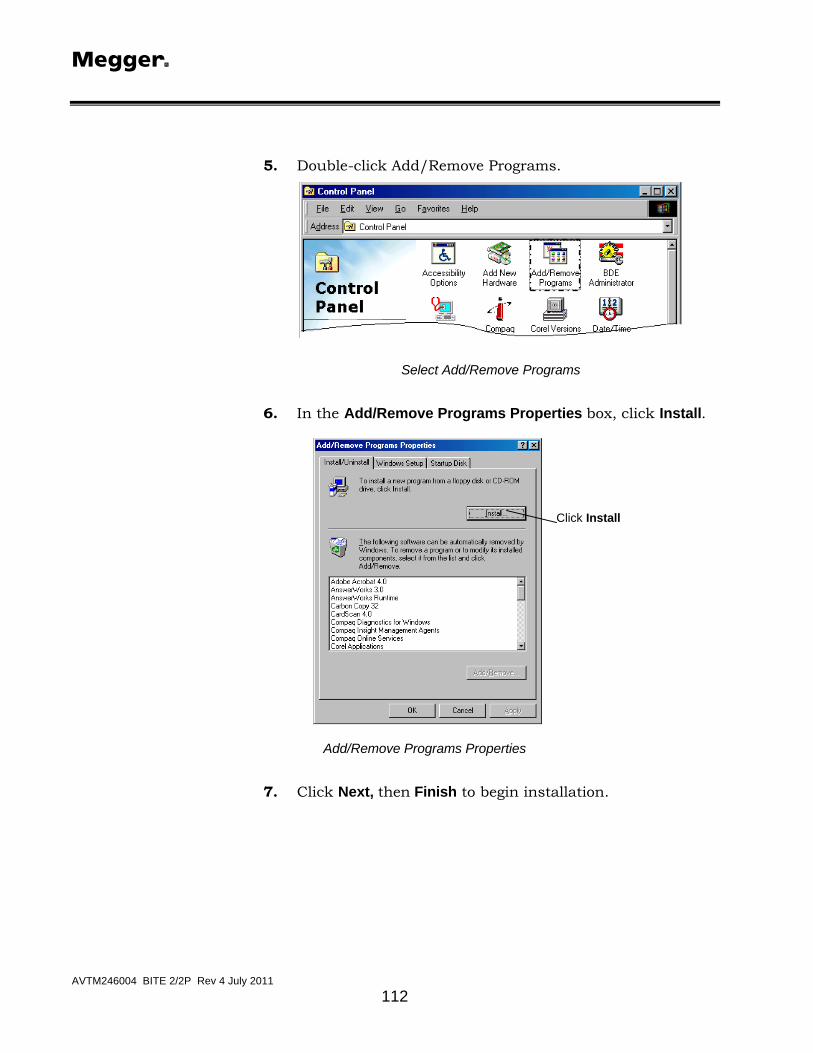
M
AVTM246004 BITE 2/2P Rev 4 July 2011
112
5. Double-click Add/Remove Programs.
Select Add/Remove Programs
6. In the Add/Remove Programs Properties box, click Install.
Click Install
Add/Remove Programs Properties
7. Click Next, then Finish to begin installation.

INSTALLATION
AVTM246004 BITE 2/2P Rev 4 July 2011
113
Install Program from Floppy Disk or CD-ROM
Run the Installation Program
8. The first screen reminds you to close all open programs if you have not yet closed them. Click Next to continue.

M
AVTM246004 BITE 2/2P Rev 4 July 2011
114
Welcome Screen
9. The software license agreement displays. Click Yes to continue.
Software License Agreement
10. A disclaimer displays. Click Yes to continue with installation.

INSTALLATION
AVTM246004 BITE 2/2P Rev 4 July 2011
115
Disclaimer
11. The next dialog box asks you to choose the destination location—the directory where the program will reside. We recommend that you accept the default location by clicking Next. (If you must choose a different directory, click on Browse and select the desired location.)
Default location
Choose Destination Location
12. Select the AVOLINK program folder by clicking Next.

M
AVTM246004 BITE 2/2P Rev 4 July 2011
116
Select Program Folder
13. The program begins to copy files, as indicated by the progress bars.
Copying Files
14. If you are installing with diskettes, you will be prompted to insert the next floppy disk. When all files are copied, a dialog box will state that the setup is complete. Click Finish to exit Setup.
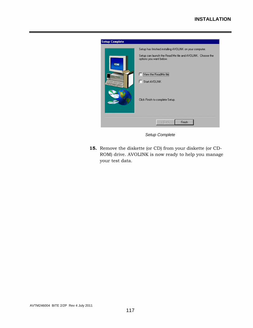
INSTALLATION
AVTM246004 BITE 2/2P Rev 4 July 2011
117
Setup Complete
15. Remove the diskette (or CD) from your diskette (or CD-ROM) drive. AVOLINK is now ready to help you manage your test data.

M
AVTM246004 BITE 2/2P Rev 4 July 2011
118
M

M
AVTM246004 BITE 2/2P Rev 4 July 2011
119
USING AVOLINK WITH THE BITE
Connecting the BITE to the PC The BITE is physically connected to the PC by means of a null-modem serial cable. You may power up the BITE before or after connection to the PC, but be sure the BITE is properly and securely connected to the PC before starting AVOLINK.
F WARNING
Make sure the BITE is disconnected from any battery under test before connecting the BITE to a PC.
For the BITE2 and the EBITE Receivers: Insert the plug of the null-modem cable (30648) into the 7-pin connector on the BITE receiver. Then insert the 9-pin end of the null-modem cable into the COM port on the PC.
NOTE: Refer to EBITE manual for transferring data from Transmitter.
For the MBITE: Connect a null-modem cable (33533) into the J5 connector on the MBITE connector panel. Insert the other end into the COM port of the PC.
Starting AVOLINK Before starting up the AVOLINK program, be sure that the PC and the BITE are securely connected by the null-modem cable.
1. Access the AVOLINK program by clicking on Start.
2. From the Programs menu, select AVOLINK and then, from the submenu, avolink.
AVOLINK automatically sets the communication parameters at 9600 baud, 8 data bits, 1 stop bit and no parity. If you need to change the parameters, use the Setup Serial Port button, as described under "Setup Serial Port" on page 132.

M
AVTM246004 BITE 2/2P Rev 4 July 2011
120
The AVOLINK Window
When you first access the AVOLINK program, the AVOLINK window displays with four tabs: Login, Send to…, Get From, and Maintenance.
AVOLINK Startup Screen
Only two tabs are active for the BITE. They are discussed in greater detail under "Transferring the BITE Test Data" on page 121.
Exit
Clicking on the button will close the AVOLINK program.
Help
Click on at any time to open the AVOLINK Help file. This is a Windows Help file, which contains Contents, Index and Find tabs to assist you with the program. The Help file also provides hypertext links to help you move among topics.
About
Click on for information regarding the version of AVOLINK that is installed on your computer.

USING AVOLINK WITH THE BITE
AVTM246004 BITE 2/2P Rev 4 July 2011
121
Transferring the BITE Test Data When you start the AVOLINK program to transfer BITE test data, the AVOLINK window displays with the Maintenance tab selected. Click on the Select Device drop-down list and select BITE. The Get From tab will now display as Import data. Click on the Import data tab.
Maintenance Tab
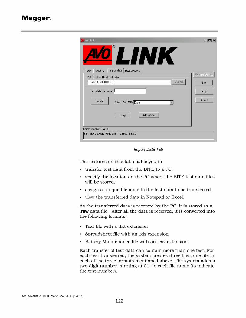
M
AVTM246004 BITE 2/2P Rev 4 July 2011
122
Import Data Tab
The features on this tab enable you to
• transfer test data from the BITE to a PC.
• specify the location on the PC where the BITE test data files will be stored.
• assign a unique filename to the test data to be transferred.
• view the transferred data in Notepad or Excel.
As the transferred data is received by the PC, it is stored as a .raw data file. After all the data is received, it is converted into the following formats:
• Text file with a .txt extension
• Spreadsheet file with an .xls extension
• Battery Maintenance file with an .csv extension
Each transfer of test data can contain more than one test. For each test transferred, the system creates three files, one file in each of the three formats mentioned above. The system adds a two-digit number, starting at 01, to each file name (to indicate the test number).
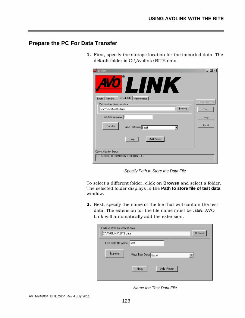
USING AVOLINK WITH THE BITE
AVTM246004 BITE 2/2P Rev 4 July 2011
123
Prepare the PC For Data Transfer
1. First, specify the storage location for the imported data. The default folder is C:\Avolink\BITE data.
Specify Path to Store the Data File
To select a different folder, click on Browse and select a folder. The selected folder displays in the Path to store file of test data window.
2. Next, specify the name of the file that will contain the test data. The extension for the file name must be .raw. AVO Link will automatically add the extension.
Name the Test Data File

M
AVTM246004 BITE 2/2P Rev 4 July 2011
124
Transfer Data
NOTE: Before transferring, you may want to disable your screen saver (if you are using a screen saver). If you have a screen saver running at the same time as the transfer, the screen saver may interrupt the transfer and cause it to abort.
1. To begin the transfer, click the Transfer button. The Transfer button toggles to Cancel, and the Communication Status window at the bottom of the AVOLINK window indicates it is waiting for data.
Transfer Button Pressed
2. Then, from the BITE, start sending the data. Each of the two following subsections describes how to send the data from one of the BITE devices.
• Sending data from the EBITE and BITE2 receivers
• Sending data from the MBITE

USING AVOLINK WITH THE BITE
AVTM246004 BITE 2/2P Rev 4 July 2011
125
Sending data from the EBITE and BITE2 Receivers
Since you connected the receiver to the PC before powering up the receiver, the display on the receiver will show the Transmit Data screen:
Y TRANSMIT DATA
N (Y/N) MENU
Transmit Data Menu
1. Press on the receiver to select Y. The receiver prompts you to select TRANSMITTER or PC.
TRANSMITTER PC MENU
Select PC
2. Press on the receiver to select PC. The screen on the receiver tells you to wait as the test results are transferred. When the transfer is complete, you are prompted to clear the data from the BITE.
Refer to the instruction manuals for the EBITE and BITE2 for information about deleting data after transferring.
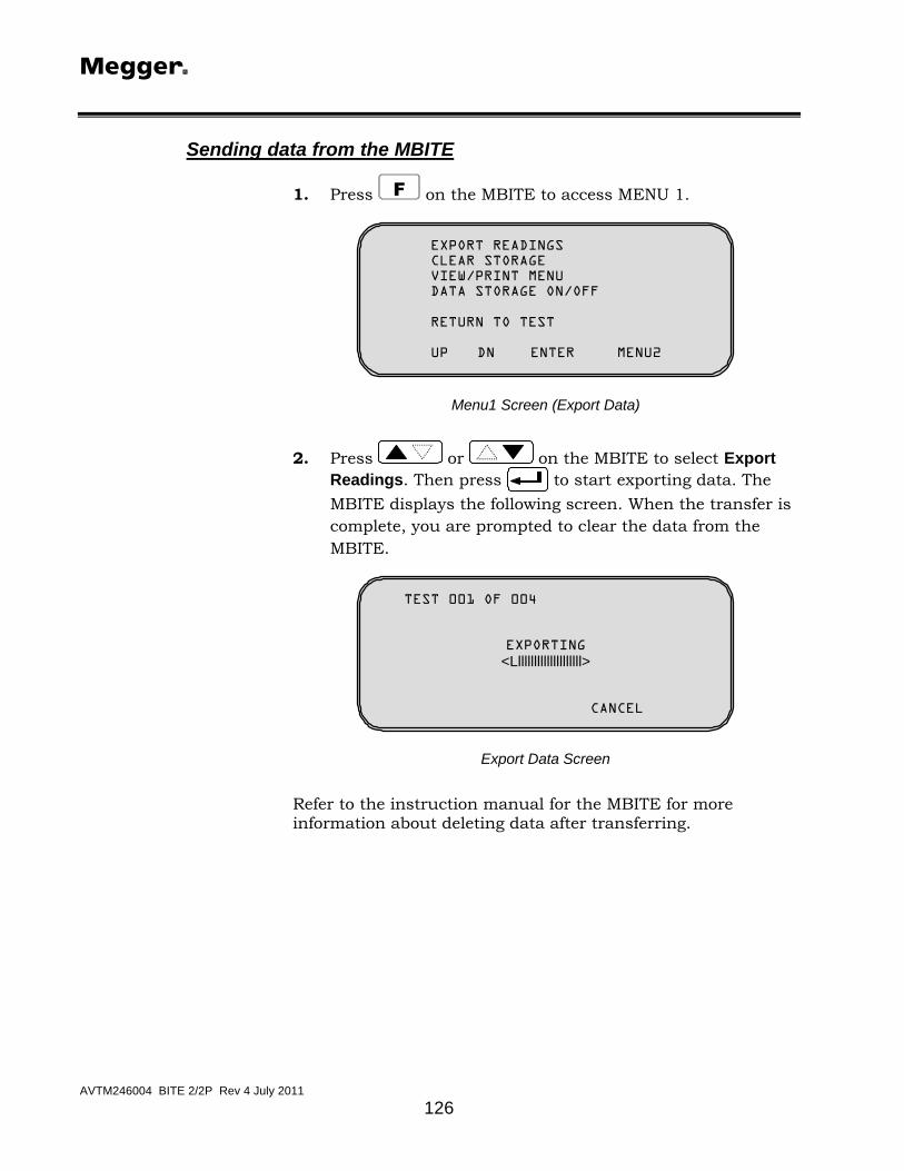
M
AVTM246004 BITE 2/2P Rev 4 July 2011
126
Sending data from the MBITE
1. Press F on the MBITE to access MENU 1.
EXPORT READINGS CLEAR STORAGE VIEW/PRINT MENU DATA STORAGE ON/OFF
RETURN TO TEST UP DN ENTER MENU2
Menu1 Screen (Export Data)
2. Press or on the MBITE to select Export Readings. Then press to start exporting data. The MBITE displays the following screen. When the transfer is complete, you are prompted to clear the data from the MBITE.
TEST 001 OF 004
EXPORTING <Lllllllllllllllllllll>
CANCEL
Export Data Screen
Refer to the instruction manual for the MBITE for more information about deleting data after transferring.

USING AVOLINK WITH THE BITE
AVTM246004 BITE 2/2P Rev 4 July 2011
127
Canceling a Transfer
To cancel a transfer, click Cancel on the AVOLINK Import Data tab. The Cancel button toggles to Transfer, and the Communication Status window indicates it is no longer waiting for data.
Cancel Button Pressed
If the data transfer is aborted, the .raw file will contain all the data that was transferred before the abort occurred. The .txt and .xls files will not be created.
Disconnect the BITE from the PC
After the transfer is complete, disconnect the null-modem cable from the BITE and from the PC.

M
AVTM246004 BITE 2/2P Rev 4 July 2011
128
Viewing and Printing Test Data To view the data files that you have transferred, click on the View Test Data drop-down list. When you select a program from the list, it automatically opens and is ready to display the data. Open the saved data file from within the viewing program.
Open Data File From Viewing Program (Excel Shown Here).
You can add a viewing program to the View Data List by clicking on Add Viewer. You can locate the viewing program in one of two ways.
Adding a Data Viewer

USING AVOLINK WITH THE BITE
AVTM246004 BITE 2/2P Rev 4 July 2011
129
AutoSearch for Viewer
1. Type the name of the viewing program in the Name of program box.
2. Click on Auto Search for Path. AVOLINK will search for the specified program and display the path to the program in the box.
3. Click OK.
Results of Auto Search
Browse for Path
1. Click on Browse for Path, then use the Select Path dialog box to find the desired viewing program.
2. Click OK.
3. Select the drive, folder and executable file for the viewing program.
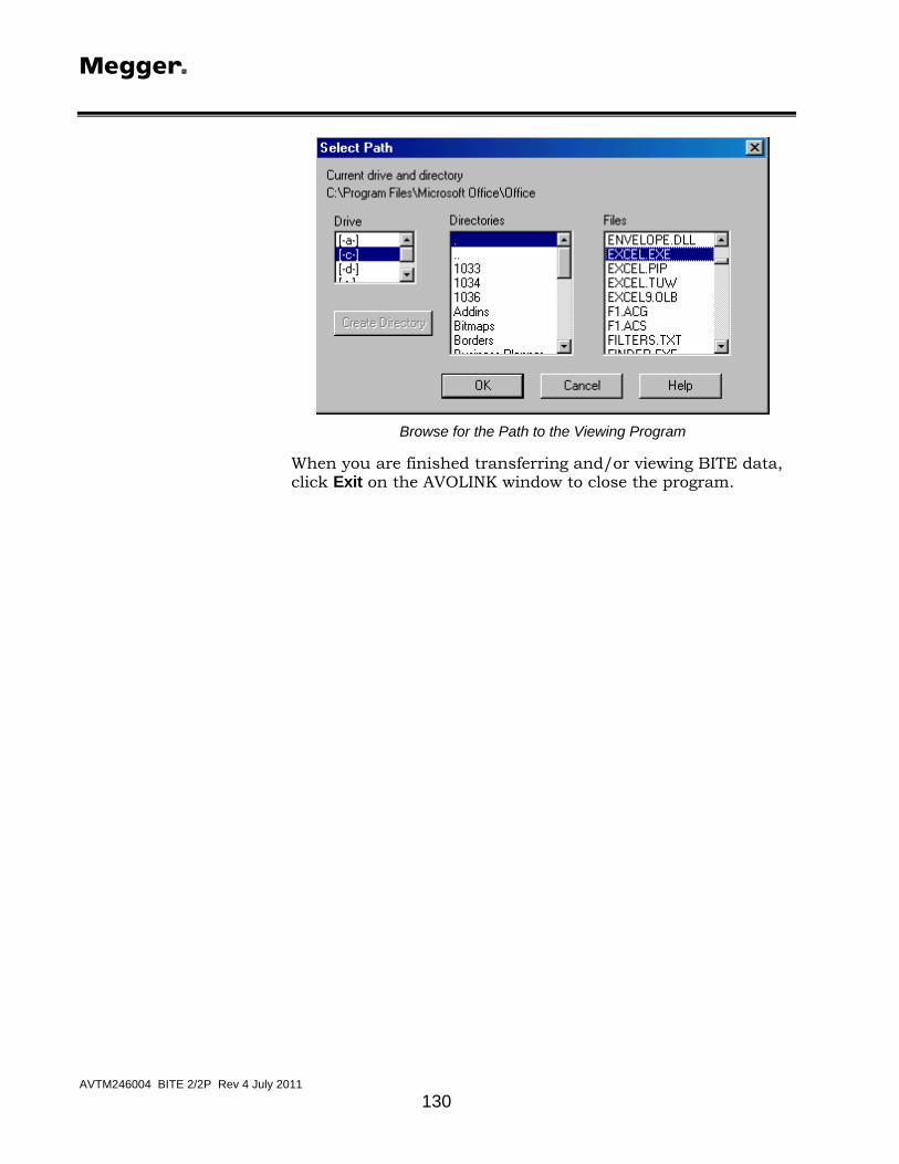
M
AVTM246004 BITE 2/2P Rev 4 July 2011
130
Browse for the Path to the Viewing Program
When you are finished transferring and/or viewing BITE data, click Exit on the AVOLINK window to close the program.

M
AVTM246004 BITE 2/2P Rev 4 July 2011
131
COMMUNICATIONS FUNCTIONS The remote device and the AVOLINK software must always operate with the same communications parameters. If you find it necessary to change the communications parameters for AVOLINK, you can do so from the Maintenance tab.
Click on Maintenance to display the Maintenance tab, and select BITE, TTR or DART from the Select Device drop-down list.
Maintenance Tab

M
AVTM246004 BITE 2/2P Rev 4 July 2011
132
Setup Serial Port When necessary, use this feature to adjust the communications parameters.
1. Click on Setup Serial Port.
Setup Serial Port
2. From the drop-down lists, pick the desired communications parameters. For the DART Analysis System, select a baud rate of 19200.
Select Baud Rate

COMMUNICATIONS FUNCTIONS
AVTM246004 BITE 2/2P Rev 4 July 2011
133
Select Parity
Select Stop Bits
Select Data Bits

M
AVTM246004 BITE 2/2P Rev 4 July 2011
134
• To save the new settings and initialize the serial port, click Save Settings.
• To leave the parameters as they were when you accessed the tab, click Restore Settings.
NOTE: Even if you have made changes and have clicked Save Settings, the settings will be restored to those in effect when you first accessed the tab.
If the Run in Test Mode check box is checked, the serial port is not used and the remote device cannot be accessed.
Run in Test Mode
The Test mode does not support all commands. The commands currently supported are.
SET.PASSWORD
SET.SETTINGS
SET.WAVEFORM (NO FILES ARE ACTUALLY TRANSFERRED)
LOGIN
LOGOUT
GET.SETTINGS
GET.PRINTERLIST
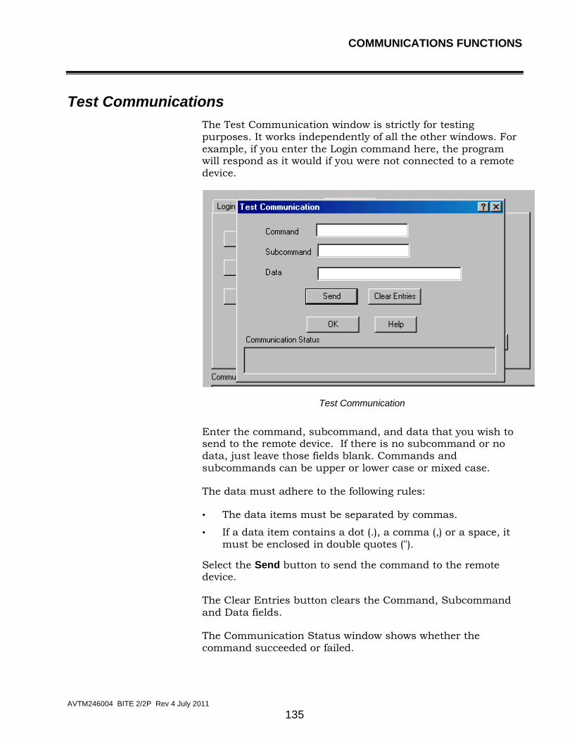
COMMUNICATIONS FUNCTIONS
AVTM246004 BITE 2/2P Rev 4 July 2011
135
Test Communications The Test Communication window is strictly for testing purposes. It works independently of all the other windows. For example, if you enter the Login command here, the program will respond as it would if you were not connected to a remote device.
Test Communication
Enter the command, subcommand, and data that you wish to send to the remote device. If there is no subcommand or no data, just leave those fields blank. Commands and subcommands can be upper or lower case or mixed case.
The data must adhere to the following rules:
• The data items must be separated by commas.
• If a data item contains a dot (.), a comma (,) or a space, it must be enclosed in double quotes (").
Select the Send button to send the command to the remote device.
The Clear Entries button clears the Command, Subcommand and Data fields.
The Communication Status window shows whether the command succeeded or failed.

M
AVTM246004 BITE 2/2P Rev 4 July 2011
136
Printer Setup Click on the Printer Setup button to display the print dialog box. The appearance of this box will vary depending on the type of printer that is connected to your PC.
Printer Setup
AVOCOM 32 AVOCOM32 provides the communication to the remote device. AVOLINK takes care of starting and terminating AVOCOM32. If you need to view the communication status, click on Start, Programs, Avolink, avocom32. The resulting window shows all commands and responses to commands going between AVOLINK, AVOCOM32 and the remote device. The following abbreviations indicate where the commands and responses are coming from:
RI: Response to command came from the remote device
RO: Command was sent to the remote device
CI: Command was received from the client (AVOLINK)