instruction manual circulator dc10 including all baths · pdf file ·...
TRANSCRIPT

Instruction ManualCirculator DC10
including all Baths
Part No. 003-30461-1-061-2 01.2002
Thermo Haake
(International)
Thermo Haake
(USA)
Thermo TemperatureControl BV(Benelux)
Dieselstraße 4 25 Nimble Hill Rd. Meerenakkerplein 31D-76227 Karlsruhe Newington, NH 03801 5652 BJ Eindhoven
Tel. +49(0)721 4094-444 Tel. 603 430 6329 Tel. 040 2300236Fax +49(0)721 4094-418 Fax 603 430 6330 Fax 040 [email protected] [email protected] [email protected] www.thermohaake.com

Table of Contents
1
1. Key to Symbols 4. . . . . . . . . . . . . . . . . . . . . . . . . . . . . 1.1 Symbols used in this manual 4. . . . . . . . . . . . . . . . . . 1.2 Symbols used on the unit 4. . . . . . . . . . . . . . . . . . . . . 1.3 Menu Tree 5. . . . . . . . . . . . . . . . . . . . . . . . . . . . . . . . . .
2. Quality Assurance 6. . . . . . . . . . . . . . . . . . . . . . . . . .
3. Your Contacts at Thermo Haake 6. . . . . . . . . . . . . .
4. Thermo Haake Test Certificate 7. . . . . . . . . . . . . . .
5. Safety Notes 8. . . . . . . . . . . . . . . . . . . . . . . . . . . . . . . .
6. Unit Description 10. . . . . . . . . . . . . . . . . . . . . . . . . . . . 6.1 Safety features 10. . . . . . . . . . . . . . . . . . . . . . . . . . . . . . 6.2 Applications 11. . . . . . . . . . . . . . . . . . . . . . . . . . . . . . . . . 6.3 Temperature ranges 11. . . . . . . . . . . . . . . . . . . . . . . . . . 6.4 Unit combinations 11. . . . . . . . . . . . . . . . . . . . . . . . . . . .
7. Unpacking / Setting Up 12. . . . . . . . . . . . . . . . . . . . . . 7.1 Transportation damage? 12. . . . . . . . . . . . . . . . . . . . . . 7.2 Ambient conditions according to DIN EN 61010 12. . 7.3 Resting time after transportation
(only for refrigerated circulators) 12. . . . . . . . . . . . . . . 7.4 Ventilation 12. . . . . . . . . . . . . . . . . . . . . . . . . . . . . . . . . . . 7.5 Information concerning the CE sign 13. . . . . . . . . . . .
8. Functional and Operating Elements 14. . . . . . . . . . 8.1 Temperature control module DC10 14. . . . . . . . . . . . . 8.2 Bath vessel “W” and integral bath ”P”
(example model) 15. . . . . . . . . . . . . . . . . . . . . . . . . . . . . 8.3 Bath vessel “B3” and integral bath ”P5” 16. . . . . . . . . 8.4 Bath vessel V15 / V26 17. . . . . . . . . . . . . . . . . . . . . . . . 8.5 Bath vessel K15 / K10 / K20 18. . . . . . . . . . . . . . . . . . .
9. Assembly 19. . . . . . . . . . . . . . . . . . . . . . . . . . . . . . . . . . 9.1 Immersion circulators with bracket mounting 21. . . . . 9.2 Open-bath circulators with angled mountings 22. . . . 9.3 Open-bath circulators with bath bridge and
stainless steel or polyacrylic baths 23. . . . . . . . . . . . . . 9.4 Open-bath cirulators with bath bridge H64 and bath vessel P14 and P21 24. . . . . . . . . . . . . . . . . . . . . . . . . . . 9.5 Open-bath cirulators with bath bridge and
bath vessel V15 and V26 25. . . . . . . . . . . . . . . . . . . . . . 9.6 Subsequently fitting a circulation set 26. . . . . . . . . . . . 9.7 Subsequently fitting a cooling coil 27. . . . . . . . . . . . . . 9.8 Fitting a lifting platform to the bridge 28. . . . . . . . . . . .

Table of Contents
2
9.9 Open-bath and heating circulators with bathbridge and polyacrylic bath W5P 29. . . . . . . . . . . . . . .
9.10 Open-bath and heating circulators with bathbridge and integral bath P5/U 29. . . . . . . . . . . . . . . . . .
9.11 Open-bath circulators with bath bridge and integral bath P5 30. . . . . . . . . . . . . . . . . . . . . . . . . . . . . .
10. Connecting Hoses 31. . . . . . . . . . . . . . . . . . . . . . . . . . 10.1 Plastic hoses 32. . . . . . . . . . . . . . . . . . . . . . . . . . . . . . . . 10.2 Tap water cooling 32. . . . . . . . . . . . . . . . . . . . . . . . . . . .
10.2.1 Connection to cooling (tap) water 32. . . . . . . . 10.3 External Cooling Devices 33. . . . . . . . . . . . . . . . . . . . . 10.4 Pressure pump 33. . . . . . . . . . . . . . . . . . . . . . . . . . . . . .
10.4.1 Temperature controlling an object in the internal bath 33. . . . . . . . . . . . . . . . . . . . . . . . . . .
10.4.2 Connection of external closed systems 33. . .
11. Filling with Bath Liquid 34. . . . . . . . . . . . . . . . . . . . . 11.1 Recommended bath liquids 34. . . . . . . . . . . . . . . . . . . . 11.2 Filling with heat transfer liquid 35. . . . . . . . . . . . . . . . .
12. Draining 36. . . . . . . . . . . . . . . . . . . . . . . . . . . . . . . . . . . .
13. Connecting Up 37. . . . . . . . . . . . . . . . . . . . . . . . . . . . . . 13.1 Connecting to the mains 37. . . . . . . . . . . . . . . . . . . . . .
13.1.1 Only for refrigerated baths K15, K10, K20, V15 and V26 37. . . . . . . . . . . . . . . . . . . . . . . . . .
13.2 Checking the liquid circuit 37. . . . . . . . . . . . . . . . . . . . . 13.3 Changing the mains plug (e.g. for Great Britain) 37. . 13.4 Fuses on the unit 38. . . . . . . . . . . . . . . . . . . . . . . . . . . .
14. Operating 39. . . . . . . . . . . . . . . . . . . . . . . . . . . . . . . . . . 14.1 Switching on 39. . . . . . . . . . . . . . . . . . . . . . . . . . . . . . . . 14.2 Heating control lamp 39. . . . . . . . . . . . . . . . . . . . . . . . . 14.3 Adjusting the variable set temperature 40. . . . . . . . . . 14.4 Adjusting the fixed temperatures F1 to F3
(facultative) 40. . . . . . . . . . . . . . . . . . . . . . . . . . . . . . . . .
15. Excess Temperature Protection 41. . . . . . . . . . . . . . 15.1 Excess temperature protection dial 41. . . . . . . . . . . . .
15.1.1 Setting the excess temperature 42. . . . . . . . . . 15.1.2 Testing the cut-off point 42. . . . . . . . . . . . . . . . .
16. Configuration 43. . . . . . . . . . . . . . . . . . . . . . . . . . . . . . . 16.1 Set value S and fixed temperatures F1 to F3 43. . . . 16.2 Adjusting the correction factors (RTA system) 44. . . . 16.3 Displaying the version of the operating software 46. . 16.4 Secured mode 46. . . . . . . . . . . . . . . . . . . . . . . . . . . . . . .

Table of Contents
3
16.5 Adjusting the LED display contrast 46. . . . . . . . . . . . . 16.6 Resolution of the temperature display 46. . . . . . . . . . . 16.7 Adjusting temperature limit values 47. . . . . . . . . . . . . .
17. Fault Displays 48. . . . . . . . . . . . . . . . . . . . . . . . . . . . . . 17.1 Excess temperature 48. . . . . . . . . . . . . . . . . . . . . . . . . . 17.2 Pump or motor overloading 48. . . . . . . . . . . . . . . . . . . . 17.3 Sensor breakage or short circuit 49. . . . . . . . . . . . . . . 17.4 Undefined fault 49. . . . . . . . . . . . . . . . . . . . . . . . . . . . . . 17.5 Fault eliminated? 49. . . . . . . . . . . . . . . . . . . . . . . . . . . . .
18. Testing the Safety Features 50. . . . . . . . . . . . . . . . . . 18.1 Excess temperature protection 50. . . . . . . . . . . . . . . . .
19. Cooling 51. . . . . . . . . . . . . . . . . . . . . . . . . . . . . . . . . . . .
20. Maintenance 52. . . . . . . . . . . . . . . . . . . . . . . . . . . . . . . . 20.1 Cleaning the fins of the liquefier 52. . . . . . . . . . . . . . . . 20.2 Discarding the unit: 52. . . . . . . . . . . . . . . . . . . . . . . . . . .
21. Disassembly for Servicing 53. . . . . . . . . . . . . . . . . . .
22. Technical specifications 54. . . . . . . . . . . . . . . . . . . . 22.1 Technical specifications of the temperature control
module DC10 according to DIN 58966 54. . . . . . . . . . 22.2 Fuse values 54. . . . . . . . . . . . . . . . . . . . . . . . . . . . . . . . . 22.3 Technical specifications of the refrigerated baths 55. 22.4 Fuse values 55. . . . . . . . . . . . . . . . . . . . . . . . . . . . . . . . . 22.5 Dimensions, material and the permissible
temperature ranges of the baths 56. . . . . . . . . . . . . . .

!
Key to Symbols
4
1. Key to Symbols
1.1 Symbols used in this manual
Warns the user of possible damage to the unit, drawsattention to the risk of injury or contains safety notesand warnings.
Denotes an important remark.
1 Indicates the next operating step to be carried outand…
⇒ …what happens as a result thereof.
1.2 Symbols used on the unit
Caution: Read the instruction manual!
Adjustment possibility for setting the cut-off point forexcess temperature protection
Menu selection
Value alteration ( ↓ ) higher / ( ↑ ) lower
Enter key
Reset button (for usage after a fault or interruption)
Key to
Sym
bo
ls
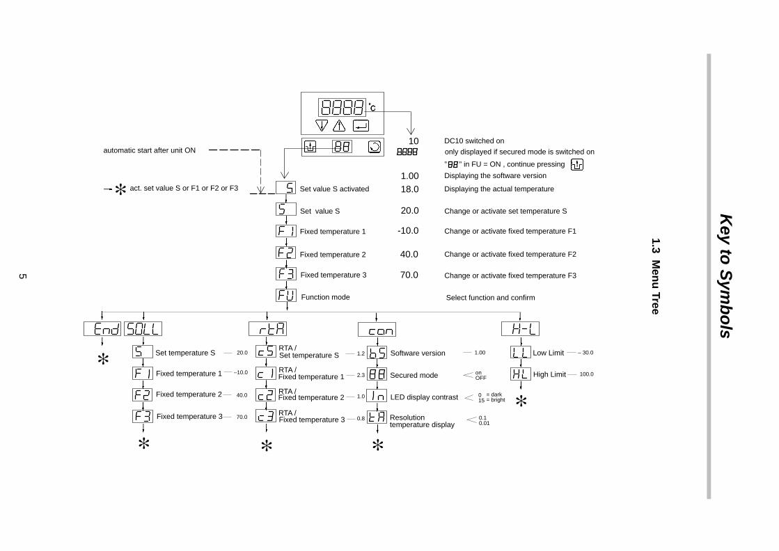
1.3 Men
u Tree
5
Fixed temperature 3
Fixed temperature 2
Fixed temperature 1Fixed temperature 1
Fixed temperature 2
Fixed temperature 3
∗ ” ” in FU = ON , continue pressing
DC10 switched on
only displayed if secured mode is switched on
Displaying the software version
Displaying the actual temperature
10
1.0018.0Set value S activated
Set value S
Set temperature SRTA /
RTA /
Software version
Secured mode
LED display contrast
Resolution
Low Limit
High Limit
– 30.0
100.0
0.10.01
015
= dark= bright
onOFF
1.001.2
2.3
1.0
0.8
20.0
–10.0
40.0
70.0
Change or activate set temperature S20.0
40.0
-10.0
70.0
Select function and confirm
act. set value S or F1 or F2 or F3
automatic start after unit ON
Fixed temperature 1
Function mode
RTA /
RTA /
∗∗
∗ ∗ ∗
Fixed temperature 2
Fixed temperature 3
Set temperature S
temperature display
Change or activate fixed temperature F1
Change or activate fixed temperature F2
Change or activate fixed temperature F3
Thermo�����TYP
V/Hz
Dieselstr. 4D–76227 KARLSRUHE
������������ � / Your Contacts at Thermo Haake
6
2. ������������ �
Dear customer,Thermo Haake implements a Quality Management Systemcertified according to EN 29001.This guarantees the presence of organizational structureswhich are necessary to ensure that our products are devel-oped, manufactured and managed according to our custom-ers expectations. Internal and external audits are carried outon a regular basis to ensure that our QMS system is fullyfunctional.We also check our products during the manufacturing pro-cess to certify that they are produced according to the speci-fications as well as to monitor correct functioning and to con-firm that they are safe. This is why we initiate this monitoringprocess of important characteristics already duringmanufacturing and record the results for future reference.
The “Final Test” label on the product is a sign that this unithas fulfilled all requirements at the time of final manufactur-ing.
Please inform us if, despite our precautionary measures,you should find any product defects. You can thus help us toavoid such faults in future.
3. Your Contacts at Thermo Haake
Please get in contact with us or the authorized agent whosupplied you with the unit if you have any further questions.
Thermo Haake (International) Thermo Haake (USA) Thermo TemperatureControl BV (Benelux)
Dieselstraße 4 25 Nimble Hill Rd. Meerenakkerplein 31D-76227 Karlsruhe, Germany Newington, NH 03801 5652 BJ EindhovenTel. +49(0)721 4094–0 Tel. 603–430–6329 Tel. 040 2300236Fax +49(0)721 4094–300 Fax 603–430–6330 Fax 040 2549485Hotline +49(0)18 05 04 22 53E-mail [email protected] [email protected] [email protected]
www.thermohaake.com www.thermohaake.com
The following specifications should be given when productenquiries are made:
– Unit name printed on the front of the unit,
– TYP as specified on the name plate.
– Version of the operating software (see chap. 16.3).

Test Certificate
7
4. Thermo Haake Test Certificate
This is to certify that the tempering device which you haveacquired and to which these instructions for operation referhas been tested and equilibrated by Thermo Haake in com-pliance with the regulations of a certified Quality AssuranceSystem according to DIN ISO 9001.Testing for constancy of temperature has been carried out inkeeping with DIN standard DIN 12876 for laboratory equip-ment. (follow–up standard to DIN standard 58966).The measuring equipment used in the testing process is re-gularly calibrated and can be traced back to the nationalnorms of the Physikalisch Technische Bundesanstalt (PTB)Deutschlands1 or to other national norms. In those caseswhere there are no norms and standards on a national level,the testing process is in keeping with currently valid technicalrules and regulations, norms and standards.All required measuring data are listed on this page of the TestCertificate.Measuring conditionsAmbient temperature: + 20°CPower supply / –frequency: 230V ± 5V / 50 Hz
respectively 115V ± 5V / 60HzSystem parametersVolume: 8 litreLiquid: WaterRated temperature: +70°CMeasuring processChecking constancy of temperature in bath according toDIN 12876, part 2 (follow–up standard to DIN 58966, part 2,paragraph 4.3)Measuring agentType of sensor used for measuring: Quartz Inexactitude
of measurement according to DIN IEC 751 +/– 0,1 KTest resultsConstancy of temperature (Width of control range): +/– 0,02 KStability of temperature (persistent): +/– 0,01 KAccuracy at +70°C: +/– 0,1 K
The individual test certificate for your thermostat will be pro-vided upon request.We and our partners shall gladly be at your disposal fora calibration of your thermostat at your premises. Justcontact us.

!
!
!
!!
!!
!
!
!
!
Safety Notes
8
5. Safety Notes
These notes are intended to draw your attention to riskswhich only YOU can recognize and avoid or overcome. Theyare intended to enhance your own safety consciousness.We have set the highest quality standards for ourselves andthis unit during development and production. Every unitmeets relevant safety regulations. The correct unit usageand proper handling is however solely your responsibility.The intended workplace should correspond to a laboratoryor pilot plant environment. The user should have an educa-tion level which is at least equivalent to a trained laboratoryworker or specialized chemist. The following list should beseen as an example.The device may not be operated if there are any doubtsregarding a safe operation due to the outer appearance(e.g. damages).A safe operation of the instrument cannot be guaran-teed if the user does not comply with this instructionmanual.Ensure that this manual is always at hand for every unitoperator.Only use this unit solely for the intended application.Repairs, alterations or modifications must only be car-ried out by specialist personnel. Consider the manufac-turer’s instruction manuals.Considerable damage can be caused by improper re-pairs. The Thermo Haake service department is at yourdisposal for repair work.Do not operate the unit with wet or oily hands.Do not expose the unit to spray water or immerse it inwater.Do not clean the unit with solvents (fire risk!), a wet clothsoaked in household detergent is normally sufficient.This device is not designed according to the standardEN 60601-1: 1990 (DIN VDE 0750-1 and IEC 601-1) andshould not be operated in rooms used for medical pur-poses and/or in the vicinity of patients.Do not move the unit from the position where it was setup during operation or when it is still hot. There is a highrisk of burns!Only use water or water with anti-freeze as bath liquid.

!
!
Safety Notes
9
The temperature controlling i.e. immersing of test tubes,Erlenmeyer flasks or similar objects directly within thecirculator constitutes normal circulator practise.We do not know which substances are contained withinthese vessels. Many substances are dangerous: • inflammable, easily ignited or explosive • hazardous to health • environmentally unsafe
You alone are responsible for the handling of these sub-stances! Our advice: • If in doubt, consult a safety specialist. • Read the product manufacturer’s or supplier’s EC
Safety Data Sheet according to directive 91/155/EEC. • Read relevant regulations concerning dangerous
materials. • Observe relevant guidelines for laboratories in your
country.
The following measures were taken for the protection ofthe operator:
• Protection Class I according to VDE 0106 T1i.e. protection against electric shocks by grounding allparts which carry the risk of electric contact.
The device must only be connected to mains recep-tacles with a protective ground.
• Protection IP 20 according to EN 60529i. e. regarding the protection against accidently touch-ing live parts and damage by foreign matter, it has beenensured that foreign bodies with a thickness or diame-ter of more than 12 mm cannot penetrate.
No special precautions were taken against the pe-netration of water and dust. The device should there-fore not be used in a dusty atmosphere or in the neigh-borhood of spray water.
Do not insert wires or tools in any of the openings.
Complete separation from the mains is requiredwhen:
• all dangers caused by this device are to beavoided,
• cleaning is carried out, • repairs or maintenance by specialist personnel is
about to be carried outComplete separation means:Pull out the mains plug!

Unit Description
10
6. Unit Description
This device contains safety elements according to categoryNFL making it suitable for unattended continuous operationwith non-combustible substances as bath liquid (water orwater with antifreeze).
The circulator pump motor is protected against thermal over-loading. Two pump speeds can be selected.
The safety element measures the surface temperature of theheating element. If this exceeds a certain temperature (dueto e.g. a leakage in the liquid circuit or a liquid shortage), thesafety element is triggered.
The DC10 circulators offer the possibility of setting this cut-off temperature variably.
6.1 Safety features
The comprehensive safety system is designed on the princi-ple of the concept of the “single fault” (EN 61010). This as-sumes that two separate faults do not occur simultaneously.This system therefore offers protection against one (single)fault. This one fault will effectively occur automatically ifyou...
• do not read this manual,
• do not correctly set the excess temperature protection,i.e. your safety reserves have already been used up.
Such faults can include e.g.:
Fault in the temperature control unit:⇒ Excess temperature ⇒ poss. fire danger
Leakage in the liquid circuit orEvaporation of heat transfer liquid:
⇒ Low liquid level ⇒ poss. fire danger,destruction ofpolyacrylic bath vessel
Pump blocked orGreat portion of antifreeze in the bath liquid:
⇒ Motor overheating ⇒ poss. fire danger
Or also:Excess temperature protection level not correctly set:
⇒ poss. fire danger

!
!
Unit Description
11
If a safety feature is triggered…
• Fault Indentification System (FIS) indicates the fault,
• the safety-relevant components of the heating unit(heating element and motor) are switched off immedi-ately i.e. the safety circuit transfers the unit to a stable,safe condition,
• the heat transfer liquid in the heating unit gradually ad-justs to ambient temperature, but…For units with switched on compressor cooling,this cooling remains functional and thus cools theheat transfer liquid to the lowest reachable temper-ature.
6.2 Applications
Open-bath circulators:
For temperature controlling samples within the circulator’sown bath.
Heating and refrigerated circulators:
For temperature controlling closed temperature control cir-cuits such reactors, heat exchangers or similar objects.Separate open vessels cannot be temperature controlled asthese circulators are only equipped with a pressure pump.
6.3 Temperature ranges
Working temperature range:
The temperature range of the circulator without additionalheating or cooling sources.
Operating temperature range:
The temperature range of the circulator which can bereached if additional heating or cooling sources are used.
Tap water can be used as a cooling source. In this case theminimum working temperature possible is approx. 3°Cabove that of the tap water temperature.
High operating temperatures mean the unit sur-faces heat up. Protective measures must be taken!
6.4 Unit combinations
A complete, ready-to-use circulator always consists of atemperature control module, a bath vessel (B3, K15, K20,W13, etc.) and a connecting element which attaches thetemperature control module to or on the bath.

!
26 !
Unpacking / Setting Up
12
7. Unpacking / Setting Up7.1 Transportation damage? • Notify carrier (forwarding merchant, railroad) etc. • Compile a damage report.
Before return delivery: • Inform dealer or manufacturer
(Small problems can often be dealt with on the spot).
7.2 Ambient conditions according to DIN EN 61010
• indoors, max. 2000 meters above sea level, • ambient temperature 5 ... 40° C, • relative humidity max. 80%/31°C (→ 50%/40°C) • excess voltage category II, contamination level 2
7.3 Resting time after transportation(only for refrigerated circulators)
As we can unfortunately not guarantee that our refrigeratedcirculators are always transported according to our recom-mendations (i.e. upright), lubrication oil can leak from thecompressor into the cooling circuit.If the refrigerated circulator is started up whilst still in thisstate, the compressor may be damaged to the lack of oil.
Therefore:
Rest the unit for 24 hours after setting up.
7.4 Ventilation
Keep all ventilation grids 26 free from obstruction to en-sure unhindered air circulation.
Blocked ventilation grids lead to increased unitheating which in turn reduces the cooling capacityand thus impairs correct functioning.

Information concerning the CE sign
13
7.5 Information concerning the CE sign
Thermo Haake measuring and control instruments carry theCE sign which confirms that they are compatible with the EUguideline 89/336/EEC (electromagnetic compatibility). Thetests are carried out according to module H (official sheetL380 of the European Community) as our quality assurancesystem is certified according to DIN / ISO 9001.
It was tested according to the strict EMV test requirementsof the EN61326-1/A1 (EMV requirements for electricalequipment for measuring technology, conduction techno-logy and laboratory usage). This means it was tested for in-terference resistance and interference emission accordingto public low-voltage mains (household and commercialusage).The following basic standards were applied in detail:
Interference resistance:EN61000–4–2 electrostatic dischargeEN61000–4–3 electromagnetic fields EN61000–4–4 fast transients EN61000–4–5 surge voltagesEN61000–4–6 wire–guided HF–signalsEN61000–4–8 magnetic field of mains frequencyEN61000–4–11 voltage drop/short–time interruption
Interference emission:CISPR16/class B wire–guided interference emission CISPR16/class B radiated interference emission
EN 61000–3–2 Voltage variations and flickering EN 61000–3–3 Over-compensation voltage flows
The application in industrial and commercial (public mains)environments is thus possible.A declaration of conformity is supplied with the ordered uniton request.
Our strict standards regarding operating quality and the re-sulting considerable amount of time and money spent on de-velopment and testing reflect our commitment to guaranteethe high level of quality of our products even under extremeelectromagnetic conditions. Practice however also showsthat even units which carry the CE sign such as monitors oranalytical instruments can be affected if their manufacturersaccept an interference (e.g. the flimmering of a monitor) asthe minimum operating quality under electromagnetic com-patibility conditions. For this reason we recommend you toobserve a minimum distance of approx. 1 m from such units.

Functional and Operating Elements
14
8. Functional and Operating Elements
8.1 Temperature control module DC10
�
�
�
� �
�
��
��
��
��
��
�
A Symbol: Read the instruction manual!
1 Mains switch 2 Reset button 3 Menu selection key
4 Heating control display 5 Menu position display 6 Set or actual temperature display 7 Value alteration (↓) higher (↑) lower 8 Enter key10 Pump outlet (depending on requirements, one of the
opening must be closed).11 Mains cable12 Fuses (if this fuse is triggered, see chap. 13.4)13 Excess temperature setting dial14 Speed reduction switch for TRS system

!
Functional and Operating Elements
15
8.2 Bath vessel “W” and integral bath ”P”(example model)
The working temperature must be limited to +100°C.
22
23
21
W13
P14
21a
21 Mounting screws for angled holderor bath bridge
21a Tapped holes for attaching the bath bridge22 Handle23 Drainage nozzle

!
!
Functional and Operating Elements
16
8.3 Bath vessel “B3” and integral bath ”P5”
The working temperature must be limited to +100°C.
4644
22
46
23
24
B3
44
25 24
P5
22 Handle23 Drainage nozzle24 Temperature control module with intermediate plate25 Bath opening (with plastic bath covering
as a standard feature)44 Pump connections
(front = to external object)(rear = return from external object)
46 Connections for tap water cooling (The flow direction can be chosen arbitrarily.)
Depending on the equipment variant, the content ofdelivery does not always include 44 and 46 but theseitems can be retro-fitted.

Functional and Operating Elements
17
8.4 Bath vessel V15 / V26
28
2930
22
23
27
V..
Rear Front
22 Handle23 Drainage nozzle27 Cooling unit mains switch28 Mains socket for temperature control unit29 Fuses (if this fuse is triggered, see chap.13.4)30 Mains cable
Functional and Operating Elements
18
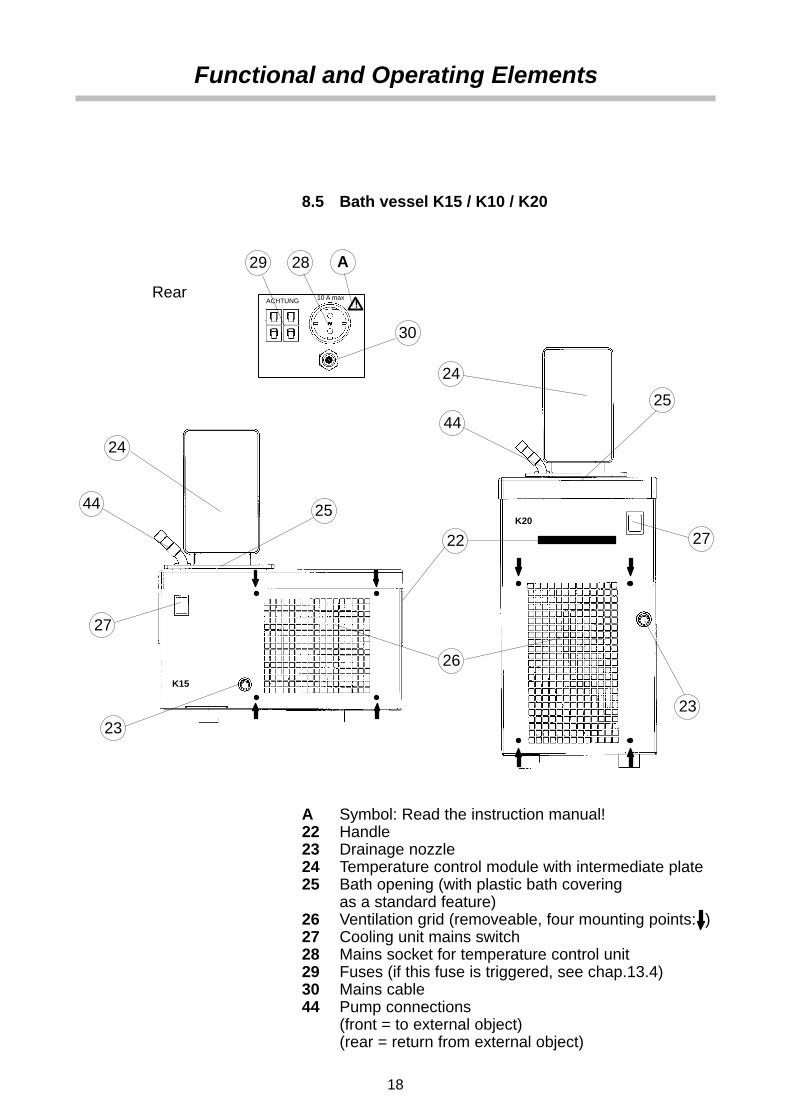
8.5 Bath vessel K15 / K10 / K20
K15
25
24
2829
23
27
!10 A maxACHTUNG
A
K20
25
24
27
23
26
22
44
44
30
Rear
A Symbol: Read the instruction manual!22 Handle23 Drainage nozzle24 Temperature control module with intermediate plate25 Bath opening (with plastic bath covering
as a standard feature)26 Ventilation grid (removeable, four mounting points: )27 Cooling unit mains switch28 Mains socket for temperature control unit29 Fuses (if this fuse is triggered, see chap.13.4)30 Mains cable44 Pump connections
(front = to external object)(rear = return from external object)

Assembly
19
9. AssemblyThe complete program is based on individual modular com-ponents which have all been separately tested to the higheststandards. In order to guarantee a high degree of availability,the components are kept on stock as separate units by us,our dealers and representatives, and grouped together justprior to shipment to our customers according to their order.These units are packed individually in order to ensure safetyduring transport. Therefore there are a few simple assemblysteps left to be carried out by the customer.
You require:1 screwdriver – size no. 2 (for Phillips screws)
As an immersion circulator with bracket mounting
see page 21
As an open-bath circulator with angled mounting and bathvessel with stainless steel W13 – W46
see page 22
As an open-bath circulator with bath bridge H62 and bathvessel with stainless steel W13 – W46 or polyacrylic bathW12P / W18P
see page 23

Assembly
20
As an open-bath circulator with bath bridge H64 and integral bats P14 / P21
see page 24
As an open-bath circulator with bath bridge H66 or H67and bath vessel V15 / V26
see page 25
As a combined open-bath and heating circulator withbath bridge H63 and polyacrylic bath W5P
see page 29
As a combined open-bath and heating circulator withbath bridge and Integral bath P5/U
see page 29/30

10
31
32
35
36
10a
!
!
Assembly
21
9.1 Immersion circulators with bracket mounting4
1 Screw angled nozzle onto pump outlet 10 and hexagonplug screw onto pump outlet 10a on the side.
Attach bracket mounting for bath vessel 32:2 Stand the temperature control module upside-down,
Dry unit first if necessary, in order to avoid expos-ing the electronics to water penetration.
3 Unscrew pair of screws 31 and remove spacers
4 Attach bracket mounting using these screws.
All containers which fulfill the following conditions can beused as the bath vessel:
• perpendicular walls, • corrosion-resistant, • minimum bath depth 150 mm (35), • wall thickness max. 26 mm (36).
Polyacrylic and other plastic vessels are instableat higher temperatures, therefore:
• Only use under supervision!
• Set the excess temperature protectionaccordingly(below 65°C for polyacrylic baths)!
• The usage of a bath bridge is highly recommendedin order to avoid a one-point load on the bath vessel!
Further on page 34 “Filling”.
An explanation on how to mount an optionalcooling coil can be found on page 27.Afterwards further on page 31.

31
33
21
33
1010a
!
Assembly
22
9.2 Open-bath circulators with angled mountings4
1 Screw angled nozzle onto pump outlet 10 and hexagonplug screw onto pump outlet 10a on the side.
Attach angled mounting for bath vessel 33:2 Stand the temperature control module upside-down,
Dry unit first if necessary, in order to avoid expos-ing the electronics to water penetration.
3 Unscrew pair of screws 31 and remove spacers,
4 Attach bracket mounting using these screws.
5 Attach the temperature control module to the rear sideof the bath using the thumbwheel screws 21.
Further on page 34 “Filling”.
An explanation on how to mount an optionalcooling coil can be found on page 27.Afterwards further on page 31.

21
31
41
40
42 37
34
38
!
Assembly
23
9.3 Open-bath circulators with bath bridge andstainless steel or polyacrylic baths4
Preparation:1 Stand the temperature control module upside-down,
Dry unit first if necessary, in order to avoid expos-ing the electronics to water penetration.
2 Unscrew and remove pair of screws 31 and hexagonplug screw 41 (pump outlet on the side),
Mounting the plate:3 Place the seal 34 onto plate 37 and slide the plate over
the shaft.
4 Insert the screws 31 through the plate 37 and screwtight.
5 Screw angled nozzle 40 onto pump outlet and hexagonplug screw 41 onto pump outlet on the side.
Mounting the bridge onto the bath vessel:6 Place the seal 42 under the plate 37.
7 Locate the plate with the attached temperature controlmodule on top of the bath vessel and secure using thefour sunken screws 38.
8 Attach the bridge to the bath vessel with the thumb-wheel screws 21 (bridge overlaps; only tighten screwslightly).
9 Fit the supplied conical bung in the thermometer holein the bridge.
Further on page 34 “Filling”.
An explanation on how to mount an optionalcooling coil can be found on page 27.Afterwards further on page 31.
An explanation on how to mount an optionallifting platform can be found on page 28.

21
31
41
40
42 37
34
38
!
Assembly
24
9.4 Open-bath cirulators with bath bridge H64 and bath vessel P14 and P214
Preparation:1 Stand the temperature control module upside-down,
Dry unit first if necessary, in order to avoid expos-ing the electronics to water penetration.
2 Unscrew and remove pair of screws 31 and hexagonplug screw 41 (pump outlet on the side),
Mounting the plate:3 Place the seal 34 onto plate 37 and slide the plate over
the shaft.
4 Insert the screws 31 through the plate 37 and screwtight.
5 Screw angled nozzle 40 onto pump outlet and hexagonplug screw 41 onto pump outlet on the side.
Mounting the bridge onto the bath vessel:6 Place the seal 42 under the plate 37.
7 Locate the plate with the attached temperature controlmodule on top of the bath vessel and secure using thefour sunken screws 38.
8 Attach the bridge to the bath vessel with the foursunken screws 21.
9 Fit the supplied conical bung in the thermometer holein the bridge.
Further on page 34 “Filling”.
An explanation on how to mount an optionalcooling coil can be found on page 27.Afterwards further on page 31.
An explanation on how to mount an optionallifting platform can be found on page 28.

21
31
41
40
42 37
34
38
38L
Q
!
Assembly
25
9.5 Open-bath cirulators with bath bridge andbath vessel V15 and V264
Preparation:1 Stand the temperature control module upside-down,
Dry unit first if necessary, in order to avoid expos-ing the electronics to water penetration.
2 Unscrew and remove pair of screws 31 and hexagonplug screw 41 (pump outlet on the side),
Mounting the plate:3 Place the seal 34 onto plate 37 and slide the plate over
the shaft.
4 Insert the screws 31 through the plate 37 and screwtight.
5 Screw angled nozzle 40 onto pump outlet and hexagonplug screw 41 onto pump outlet on the side.
Mounting the bridge onto the bath vessel:6 Place the seal 42 under the plate 37.
7 Locate the plate with the attached temperature controlmodule on the bath bridge L (standard version) or Q(special version) and secure using the four sunkenscrews 38.
8 Attach the bridge to the bath vessel with the thumb-wheel screws 21.
9 Fit the supplied conical bung in the thermometer holein the bridge.
Further on page 34 “Filling”.
An explanation on how to mount an optionalcooling coil can be found on page 27.Afterwards further on page 31.
An explanation on how to mount an optionallifting platform can be found on page 28.

37
38
44
43
44
41
a
a
bc
!
Assembly
26
9.6 Subsequently fitting a circulation set
1 Remove the temperature control module with platefrom the bath bridge (unscrew the four sunkenscrews 38).
2 Stand the temperature control module upside-down,
Dry unit first if necessary, in order to avoid expos-ing the electronics to water penetration.
3 Unscrew angled nozzle 40 from pump outlet and hexa-gon plug screw 41 from pump outlet on the side,
4 Remove the covering plate from the marked openings(↓↓).
5 Insert hexagon plug screw 41 into a and nozzle 43 intopump outlet b on the side.
6 From below insert circulation set 44 into the plate (↓↓)and fix with sunken screw.
7 Insert tube 44a through plate and circulation set intonozzle 43 and fix it with setscrew c (the required allenkey is supplied).
Mount the temperature control module with plate to the bathbridge.

A
B
37
Assembly
27
9.7 Subsequently fitting a cooling coil4
Open-bath circulators with bracket mounting A orangled mounting B
1 Remove the hexagon nuts from the cooling coil.
2 Insert cooling coil from below through the bracket orangled mounting as illustrated.
The cooling coil now surrounds the shaft of the temper-ature control module.
3 Adjust the cooling coil (it should be equally spacedaway from the shaft on all sides) and screw tight usinghexagon nuts.
4 Attach the cooling coil with the bracket or angledmounting to the unit according to the instructions onpages 21 and 22.
Open-bath circulators with a plate on a bath bridge:
1 Remove the covering plate from the marked openings(↓↓).
2 Insert cooling coil from below into the plate 37 as illus-trated.
The cooling coil now surrounds the shaft of the temper-ature control module.
3 Adjust the cooling coil (it should be equally spacedaway from the shaft on all sides) and screw tight usingusing the screw which previously held the coveringplate
50
51
54
53
52
55
Assembly
28
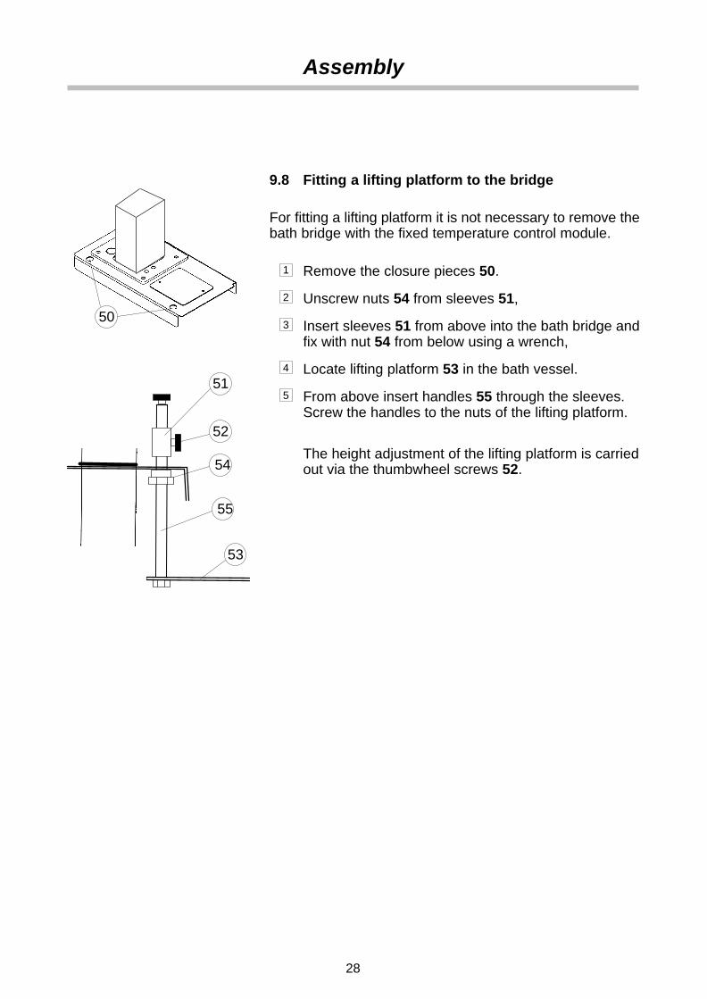
9.8 Fitting a lifting platform to the bridge4
For fitting a lifting platform it is not necessary to remove thebath bridge with the fixed temperature control module.
1 Remove the closure pieces 50.
2 Unscrew nuts 54 from sleeves 51,
3 Insert sleeves 51 from above into the bath bridge andfix with nut 54 from below using a wrench,
4 Locate lifting platform 53 in the bath vessel.
5 From above insert handles 55 through the sleeves.Screw the handles to the nuts of the lifting platform.
The height adjustment of the lifting platform is carriedout via the thumbwheel screws 52.

21
38
!
!
Assembly
29
9.9 Open-bath and heating circulators with bathbridge and polyacrylic bath W5P4
The highest working temperature must be limitedto +60°C.
Mounting the bridge onto the bath vessel:6 Attach the bridge to the bath vessel with the thumb-
wheel screws 21 (bridge overlaps; only tighten screwslightly).
7 Fit the supplied conical bungs in the thermometer holesin the bridge.
9.10 Open-bath and heating circulators with bathbridge and integral bath P5/U
The highest working temperature must be limitedto +120°C.
Mounting the bridge onto the bath vessel:1 Locate the plate with the attached temperature control
module on top of the bath vessel and secure it using thefour sunken screws 38.
2 Fit the supplied conical bung in the thermometer holein the bridge.
Further on page 34 “Filling”.
Further on page 31 “Connecting Hoses”.

21
31
41
40
37
34
!
!
Assembly
30
9.11 Open-bath circulators with bath bridge and integral bath P54
The highest working temperature must be limitedto +120°C.
Preparation:1 Stand the temperature control module upside-down,
Dry unit first if necessary, in order to avoid expos-ing the electronics to water penetration.
2 Unscrew and remove pair of screws 31 and hexagonplug screw 41 (pump outlet on the side),
Mounting the plate:3 Place the seal 34 onto plate 37 and slide the plate over
the shaft.
4 Insert the screws 31 through the plate 37 and screwtight.
5 Screw angled nozzle 40 onto pump outlet and hexagonplug screw 41 onto pump outlet on the side.
Mounting the bridge onto the bath vessel:6 Locate the plate 37 with the attached temperature con-
trol module on top of the bath vessel, .and secure usingthe four sunken screws 21.
7 Fit the supplied conical bung in the thermometer holein the bridge.
Further on page 34 “Filling”.
An explanation on how to mount an optionalcooling coil can be found on page 27.Afterwards further on page 31.
An explanation on how to mount an optionallifting platform can be found on page 28.

A
!
!
!
!
!
Connecting Hoses
31
10. Connecting Hoses4
Pump nozzle A:front: outlet to external object (pressure side)rear: return flow from external object
Hoses are normally used to connect the pump with an exter-nal vessel. If objects are to be temperature controlled in theinternal bath only, connect the pump nozzles A with a shorthose with a min. length of 50 cm in order to achieve a bettertemperature constancy.
General recommendations concerning the max. allowablelength of hoses cannot be given. It all depends largely on thesize, form and material of the external vessel to be tempera-ture controlled. It should be understood that the length of ahose and its diameter combined with the circulating capacityhave a large effect on the temperature control effectiveness.Whenever possible, the decision should be made in favor ofthe wider hose diameter and the vessel to be temperaturecontrolled should be placed as close as possible to the circu-lator.
High operating temperatures will lead to high tem-peratures on the hose surface, this is even more soat the metal nozzles. In this case: DO NOT TOUCH!The required hose material is dependent on theheat transfer liquid used.Hoses must not be folded or bent!A wide radius should be used if turns have to bemade!Hoses may become brittle after prolonged use orthey may get very soft. They should, therefore, bechecked regularly and exchanged if necessary!Secure all hose connections using hose clamps!
A
A
B
Connecting Hoses
32
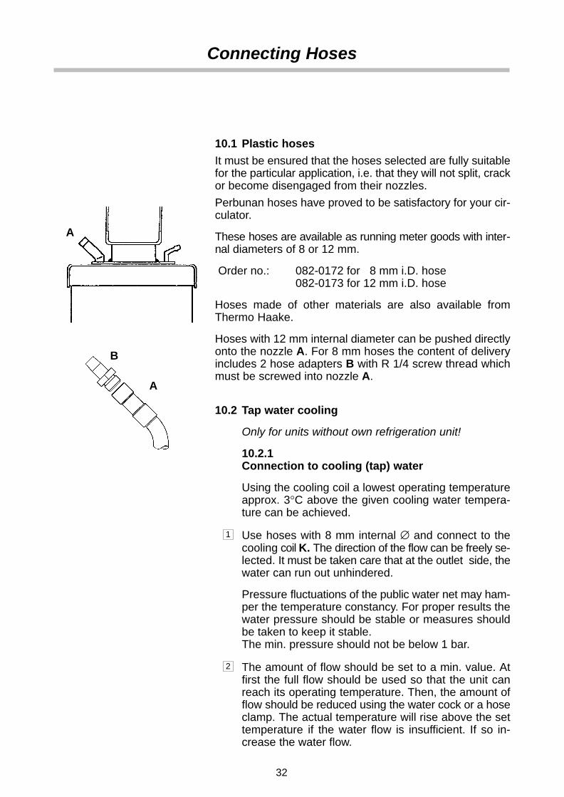
10.1 Plastic hoses
It must be ensured that the hoses selected are fully suitablefor the particular application, i.e. that they will not split, crackor become disengaged from their nozzles.
Perbunan hoses have proved to be satisfactory for your cir-culator.
These hoses are available as running meter goods with inter-nal diameters of 8 or 12 mm.
Order no.: 082-0172 for 8 mm i.D. hose 082-0173 for 12 mm i.D. hose
Hoses made of other materials are also available fromThermo Haake.
Hoses with 12 mm internal diameter can be pushed directlyonto the nozzle A. For 8 mm hoses the content of deliveryincludes 2 hose adapters B with R 1/4 screw thread whichmust be screwed into nozzle A.
10.2 Tap water cooling
Only for units without own refrigeration unit!
10.2.1Connection to cooling (tap) water
Using the cooling coil a lowest operating temperatureapprox. 3°C above the given cooling water tempera-ture can be achieved.
1 Use hoses with 8 mm internal ∅ and connect to thecooling coil K. The direction of the flow can be freely se-lected. It must be taken care that at the outlet side, thewater can run out unhindered.
Pressure fluctuations of the public water net may ham-per the temperature constancy. For proper results thewater pressure should be stable or measures shouldbe taken to keep it stable.The min. pressure should not be below 1 bar.
2 The amount of flow should be set to a min. value. Atfirst the full flow should be used so that the unit canreach its operating temperature. Then, the amount offlow should be reduced using the water cock or a hoseclamp. The actual temperature will rise above the settemperature if the water flow is insufficient. If so in-crease the water flow.

Heating / Open-bath circulator
ExternalObject
Flow-ThroughCooler
A
Heating / Open-bath circulator
ExternalObject
Connecting Hoses
33
10.3 External Cooling Devices
With immersion and flow-through coolers from ThermoHaake, the heat transfer liquid can be cooled down consider-ably below 0°C and the circulator can be rendered indepen-dent of tap water.
A flow-through cooler should be used for the circulator andbath B3. The flow-through cooler is hooked up into the returnflow line of the external vessel and from there to the circula-tor (see Fig.).
Immersion coolers have proven themselves especially suit-able for open-bath circulators with angled brackets or thebath bridge H62.The fitting opening is already provided in the bath bridgeH62.
The assembly and application are described in the instruc-tion manual of the cooler in detail.
10.4 Pressure pump
10.4.1Temperature controlling an object in the
internal bath
Connect pressure and return nozzle A with a shorthose.
10.4.2Connection of external closed systems
E.g. instruments with a pressure-tight temperaturejacket or coil or a heat exchanger.
Hose connection:From the pressure port (at the front) to the external ob-ject and then back to the return port (at the rear).
If it cannot be avoided that the external object is si-tuated higher than the circulator, the heat transfer willonly not flow back on the condition that the system iscompletely tight and leak-free. To be on the safe sideit may be considered necessary to fit stop cocks to theinlet and outlet hoses.

!
! Important !
Filling
34
11. Filling with Bath Liquid 4
11.1 Recommended bath liquids
5 to 95°C Distilled Water
• Normal tap water leads to calcareous deposits neces-sitating frequent unit decalcification.
Calcium tends to deposit itself on the heating ele-ment. The heating capacity is reduced and servicelife shortened!
• Water, of course, can be employed up to 95°C, howev-er above 80°C water vaporization reaches a levelwhich necessitates the liquid to be constantly replenis-hed.
–30 to 80°C Water with Antifreeze
In applications below 5°C the water has to be mixed with anantifreeze. In doing so, the amount of antifreeze addedshould cover a temperature range 5°C lower (but max.–30°C) than the operating temperature of the particularapplication. This will prevent the water from gelling (freezing)in the area of the evaporating coil the surface area of whichis much colder than the working temperature. An excess ofantifreeze deteriorates the temperature accuracy due to itshigh viscosity.
Thermo Haake takes no responsibility for damagescaused by the selection of an unsuitable bath liquid.

2
Filling
35
11.2 Filling with heat transfer liquid
Filling level of the interior bath:max. up to 2.0 cm below the cover plate,min. up to 5.0 cm below the cover plate.
When working with water or water with antifreeze:or with oil below ambient temperature:the filling level should be 2 cm below the deck plate.
When working with oil above 80°C:Keep level somewhat lower. Oil expands when beingheated. Rule of thumb: 10% volume increase per 100°C heatincrease.
External systems included within the circulating circuit haveto be filled with the same heat transfer liquid in order to avoidtoo much liquid being drawn from the internal bath.
The bath level should be checked when the preset tem-perature has been reached!
Quite often closed external systems cannot be prefilled assuggested. In this case the internal bath of the unit has to befilled to the max. level. After starting the unit, the pump willfeed the necessary liquid to the external system. Should thedemand be higher than the volume difference between highand low, the low liquid level sensor will be activated and thepump switched off.
In this case:
1 Replenish the liquid,
2 Reset the unit:Depress the key 2 (at the front).
⇒ The unit starts up again
3 Repeat this action if necessary.

23
!
Draining
36
12. Draining
The temp. control unit is drained at the nozzle 23.
1 Place a suitable vessel underneath nozzle.
Bear in mind that the liquid will run out in a slight arc.
2 Turn plug slowly until it becomes disengaged from thethread. A pin will prevent the liquid from running outright away.
3 Pull out plug (pin) in one quick motion. The liquid willstart to run out.
4 Possible residues can be drained by tilting the circula-tor slightly.
Hot heat transfer liquid should not be drained!When certain conditions make draining necessary,please act safety conscious: Wear protectiveclothing and protective gloves!

28
28
230 V
115 V
11
30
30
29
29
12
!
!
Connecting Up
37
13. Connecting Up
13.1 Connecting to the mains
Only attach this unit to mains sockets with a grounded earth.Compare the local mains voltage with the specifications writ-ten on the name plate. Voltage deviations of +/- 10% are per-missible. The socket must be rated as suitable for the totalpower consumption of the unit.
13.1.1 Only for refrigerated baths K15, K10, K20,V15 and V26
1 Insert the mains plug 11 of the temperature con-trol module into the socket 28 at the rear of the re-frigerated bath.
2 Connect the refrigerated bath’s mains plug 30 toa grounded mains socket.
Socket 28 is live as soon as this connectionhas been made whether the refrigerated bathhas been switched on at the mains switch ornot!
13.2 Checking the liquid circuit
Before switching on, check again to make sure that the pres-sure and suction ports are connected with each other – oralternatively if an external object is to be temperature con-trolled, that the hoses are connected correctly and secured(see chapter 10.4).
13.3 Changing the mains plug (e.g. for Great Britain)
This should only be carried out by qualified spe-cialist personnel!
The mains cable wires have the following colors:
Brown = Live
Blue = Neutral
Green/Yellow= Earth

!
!
Connecting Up
38
13.4 Fuses on the unit
All units are equipped with automatic thermally-triggeredfuses.
If the fuse (12/29) has triggered…
• the fuse does not have to be exchanged – resetting suf-fices;
• a white marking is visible;
• a certain cooling down time should be allowed (approx.5 min) before the (dip) switch can be pressed again.
Do not use tools; do not use force. Both destroy thefuse.
If the fuse should be triggered again after resetting,the unit probably has a defect. In this case the unitshould be sent in for servicing.
113
5
6
14
4
Operating
39
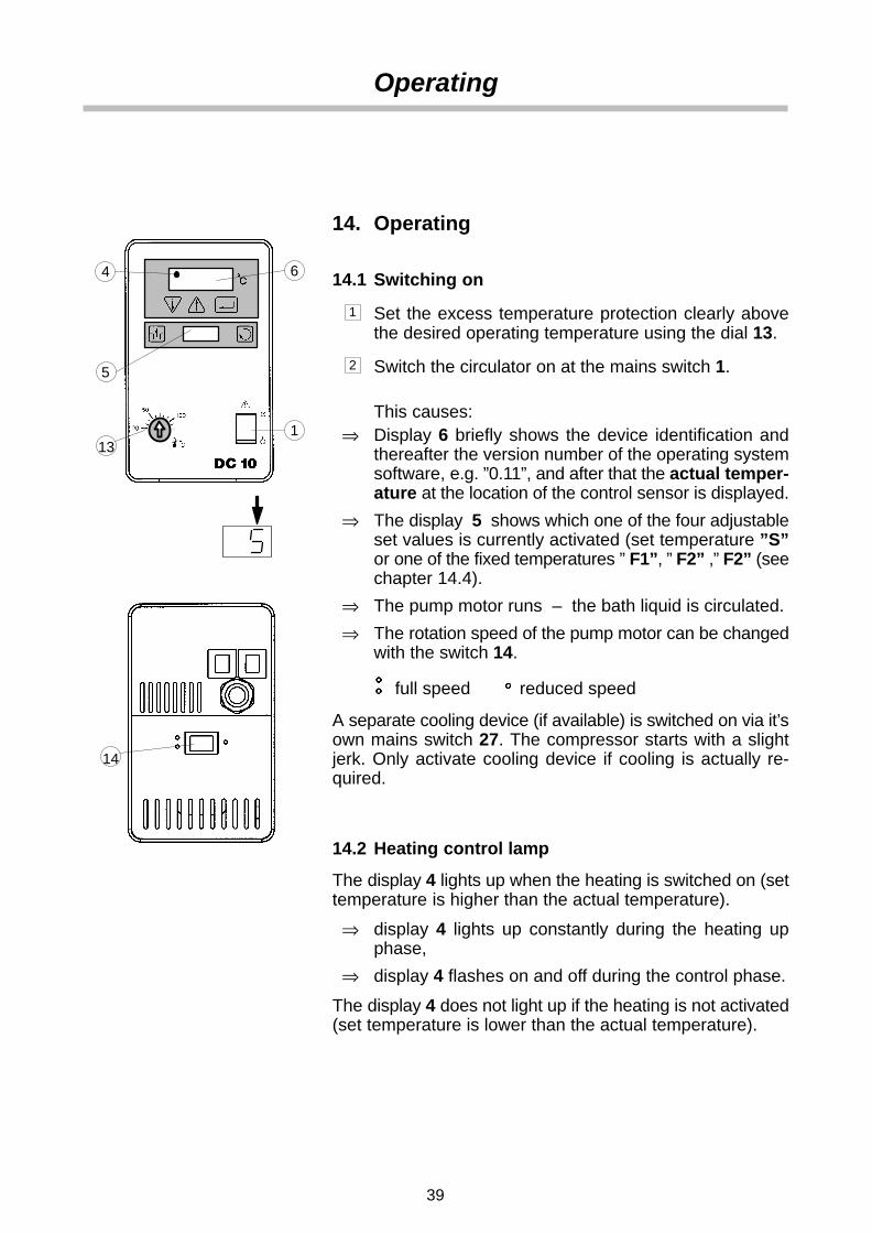
14. Operating
14.1 Switching on
1 Set the excess temperature protection clearly abovethe desired operating temperature using the dial 13.
2 Switch the circulator on at the mains switch 1.
This causes:⇒ Display 6 briefly shows the device identification and
thereafter the version number of the operating systemsoftware, e.g. ”0.11”, and after that the actual temper-ature at the location of the control sensor is displayed.
⇒ The display 5 shows which one of the four adjustableset values is currently activated (set temperature ”S”or one of the fixed temperatures ” F1”, ” F2” ,” F2” (seechapter 14.4).
⇒ The pump motor runs – the bath liquid is circulated.
⇒ The rotation speed of the pump motor can be changedwith the switch 14.
full speed reduced speed
A separate cooling device (if available) is switched on via it’sown mains switch 27. The compressor starts with a slightjerk. Only activate cooling device if cooling is actually re-quired.
14.2 Heating control lamp
The display 4 lights up when the heating is switched on (settemperature is higher than the actual temperature).
⇒ display 4 lights up constantly during the heating upphase,
⇒ display 4 flashes on and off during the control phase.
The display 4 does not light up if the heating is not activated(set temperature is lower than the actual temperature).

7
6
3
8
5
Operating
40
14.3 Adjusting the variable set temperature
1 Press the menu button 3:
⇒ A left-justified ”S” appears in the small display 5(for set temperature adjustment).
2 Increase ( ↑ ) or decrease ( ↓ ) the value shown in thedisplay 6 with the buttons 7 . The first degree of tem-perature change is thereby passed slowly and thereaf-ter the rate of temperature change in the display is fivetimes faster.
3 Press the enter button 8.
⇒ The selected value is stored as new set temperatureand activated.
The new value is not saved until the Enter buttonhas been pressed. The circulator continues to usethe old set value.
The display 6 automatically switches back to actual temper-ature display after a short time.
14.4 Adjusting the fixed temperatures F1 to F3(facultative)
This device permits permanent storage of three fixed tem-peratures which can be activated when required.
1 Press the menu button 3 :
⇒ The small display 5 shows F1 (for fixed temperature 1 ),F2 or F3 .
2 Press the buttons 7 to increase ( ↑ ) or decrease ( ↓ )the value shown in the display 6 .
3 Press the enter button 8 .
⇒ The selected value is stored as fixed temperature F1,F2 or F3 and activated as currently valid set value.
The display 6 automatically switches back to actual temper-ature display after a short time. At the same time the smalldisplay 5 shows whether the temperature set point S, F1,F2 or F3 is currently active.
To activate another set value, press the menu button 3 untilthe designator of the desired set point (e.g. ”S” ) is shown inthe display 5. Then press the button 8 to confirm withoutchanging the value.

13
6
2
13
7
Excess Temperature Protection
41
15. Excess Temperature Protection
If one of the safety devices is triggered:
• The fault cause is shown in the display 6 (see also chapter 17.).
• all voltage conducting unit components (the heatingelement and pump motor) are switched off immediatelyi.e. the safety circuit transfers the unit to a stable, safecondition.
The fault cause must be identified and remedied.
After the fault has been eliminated the unit can be startedagain by pressing the Reset key 2.
15.1 Excess temperature protection dial
It offers protection against dangers caused by an uncon-trolled heating up of the heat transfer liquid above the de-sired set temperature.
The cut-off temperature is adjusted with the excess temper-ature setting dial 13.
Proper protection can only be guaranteed if thecut-off point has been correctly set.
There are two main aims for correct setting:
• Safety (primary importance):Protection against ignition of the heat transfer liquid.The cut-off point must be set at least 25°C below thefire point of the bath liquid used.
• Protection of the object to be temperature con-trolled (secondary importance):Additional protection, e.g. of a biological sample. Thecut-off point should be set as close as possible to thedesired temperature value.

13
Excess Temperature Protection
42
15.1.1 Setting the excess temperature
The cut-off point is set with the excess temperature dial 13with a rough scale of temperature values arranged aroundit. This scale, of course, can only serve as an approximatesetting means for this cut-off point. However, the cut-off pointcan be determined to act exactly if the following procedureis adhered to:
If for instance a bath liquid has a fire point of 60°C the unitshould cut off after reaching 35°C at the latest:
1 First set the desired set value “ ” using keys 7 (↑) or(↓) to exactly 35°C.
2 After the circulator has reached this temperature, turnthe excess temperature dial 13 backwards very slowly(to the left) until the unit cuts off (fault message on dis-play 6).
3 Reset the unit via the Reset key 2 after the heat transferliquid has cooled down somewhat.
4 Then set the set temperature to the actual temperature(< 35°C).
⇒ The unit can now be used for temperatures below35°C. As soon as 35°C is reached, it is securelyswitched off.
15.1.2 Testing the cut-off point
Set the set temperature to a higher value than 35°C, set theunit to heat up and watch the digital display or thermometer.The value indicated when the alarm goes off is the real cut-off temperature. The reaching of the cut-off point is indicatedat the display by the following message:

7
6
3
8
5
Configuration
43
16. Configuration
The device is completely ready for operation after definingthe desired set temperature and adjusting the overtempera-ture protection. It is furthermore possible to adjust or call-upseveral functions in the function mode ”FU”.
SOLL RTA CON H–LEND
FU
Quit configu–ration mode
Adjust setvalues S andF1 to F3
Adjust correc-tion factors cSand c1 to c3
Version no.,temperatureresolution, etc.
High and lowtemperaturelimits
1 Switch to function mode by pressing the menu button 3 several times (until display 5 shows FU).
2 Switch to the desired function SOLL, RTA, CON or H–Lwith the arrow buttons 7. Press the enter button 8 toconfirm the selection made.
3 Move around through the submenus with the menubutton 3 (see chapter ”Menu Tree”).
4 A further press of the menu button 3 quits functionmode and returns to display of the actual temperature.
Display 6 always returns automatically to actual tem-perature display after a short time.
END is provided to skip function mode without makingany settings.
16.1 Set value S and fixed temperatures F1 to F3
The adjustment has already been made in chap. 14.3 and14.4. In the function mode it is also possible to adjust andchange these set values without activating them.
1 Press the arrow buttons 7 in the menu FU to changeto the SOLL function. Press the enter button 8 to con-firm this selection.
2 Press the menu button 3 to move through the subme-nus S, F1 to F3 (the procedure for making adjustmentsis the same as in chapter 14.3).
A correcting factor c should be associated with each value:S ⇔ cS, F1 ⇔ c1 ... (see chapter 16.2).

Configuration
44
16.2 Adjusting the correction factors (RTA system)
Display 6 shows the actual temperature at the control sensor.
This temperature does not correspond directly to the tem-perature in the circulator’s bath and even less to the temper-ature in the external connected system.
The temperature difference is determined by measuring theactual current temperature using a suitable measuring de-vice (calibrated or gauged thermometer).
This is how the correction factor c (RTA system) is enteredinto the circulator. It remains stored in the circulator and isautomatically assigned to the corresponding set tempera-ture.
The same as for the set values in chap. 14.4, four correctionfactors can be stored: cS , c1 , c2 and c3 , whereby, forexample, c1 is the correction value associated with F1.
The resolution of the correction factor according to the RTAsystem is 0.01°C and the possible range of variation is ±9.9°C.
Entry (see also the example on the next page):
1 Switch to the RTA function with the arrow buttons 7 inthe menu FU. Press the enter button 8 to confirm thisselection.
2 Press the menu button 3:
⇒ The small display 5 shows cS (correction factor forworking with the set temperature S ).
3 Set the determined temperature difference on the dis-play 6 with the buttons 7.
4 Press the enter button 8.
⇒ This confirms the value as new correction factor cS.
Proceed analogously as described for cS to adjust the cor-rection factors c1 to c3 for the set values F1 to F3.
The new value is not saved until the Enter buttonhas been pressed. The circulator continues to usethe old value.Warning: The correction factor ”c” may have to bedetermined again if the set temperature is altered!
The display 6 automatically switches back to actual temper-ature display after a short time.
After the Enter button 8 has been depressed, the correctionvalue (like the set value) remains stored even in case of apower failure.

Configuration
45
Example:
Set value programmed at the circulator Tset = 70.7°C
Actual temperature in bath / system Tact = 70.5°C
⇒ Deviation, calculated according to∆T = Tset – Tact
∆T = 0.2°C
⇒ Entry of the corrected value ∆T ascorrection factor “ ” = +0.2°C
The temperature control is thus internally altered so that thedesired 70.7°C is also attained in the external system. Thetemperature displayed at the circulator and that of the exter-nal system now correspond with each other.

!
Configuration
46
16.3 Displaying the version of the operating software
It is often necessary to know the version number of the soft-ware for service and other manufacturer inquiries.
1 Change to con in the menu FU and press button 8to confirm. Press button 3 to switch to BS . The versionnumber appears in the upper display 6 .
16.4 Secured mode
1 Change to con in the menu FU and press button 8to confirm. Press button 3 to switch to 88 .
2 Switch security mode ON or OFF with the arrow but-tons 7 and press button 8 to confirm.
Secured mode: ONThe temperature control module switches to the securedmode in case of a power failure or if it is switched on via themains switch. Display 6 flashes over all segments .Switching on again is only possible after the reset button 2has been pressed. This is due to safety reasons.The unit reacts in the same way if is switched on via a mainsswitch in the laboratory.
Secured mode: OFFAfter a power failure or if it is switched on via the mains switchthe temperature control module will switch on and start heat-ing corresponding to the stored values and the last tempera-ture used.
Please consider any possible resulting risks!
16.5 Adjusting the LED display contrast
1 Change to con in the menu FU and press button 8to confirm. Switch to In with button 3.
2 Press the arrow buttons 7 to change the display con-trast (0 to 15) and then press button 8 to confirm thesetting.
16.6 Resolution of the temperature display
1 Change to con in the menu FU and press button 8to confirm. Switch to tA with button 3 .
2 Choose the resolution (0.1 or 0.01 °C) with the but-tons 7 and then press the button 8 to confirm (0.01°Cresolution is available only in the display range from–9.5 to +99.5 °C).

!
Configuration
47
16.7 Adjusting temperature limit values
The setting range of the operating temperature of the circula-tor can be limited if the application requires this.
This is not a safety element but merely an aid tohelp avoid user faults when operating the unit. Theexcess temperature protection must be set sepa-rately.
1 Change to the function H–L with the arrow buttons 7in the menu FU. Then press the enter button 8 to con-firm the selection.
2 Press the menu button 3 :
⇒ The small display 5 shows LL (Low Limit temperaturevalue).
3 Set the desired limit value with the arrow buttons 7 (thelowest possible temperature is –30°C).
4 Press the enter button 8 .
⇒ The chosen value is stored as low limit value LL .
To set the high limit value HL, proceed analogously as des-cribed for LL.HL (High Limit): The highest possible temperature is 100°C.
The new value is not saved until the Enter key hasbeen pressed. The circulator continues to use theold value.
5 Press the menu button 3 again to quit function modeand return to display of the actual temperature.Or just wait until the displays 5 and 6 automaticallyreturn to actual temperature display mode after a shortdelay.

6
2
5
Fault Displays
48
17. Fault Displays
Display 6 shows the fault message ” XXXX ”.” ” is shown on display 5.The heating element and pump are completelyswitched off.
The following faults are possible:
= Excess temperature
= Pump or motor overloading
= Sensor breakage or short circuit
= Undefined fault
17.1 Excess temperature
The low liquid level protection can be triggered if:
• Excess temperature has been set too closely tothe desired working temperature
⇒ increase value slightly according to specifi-cations made in chapter 15.1.1.
• the control function is defective
⇒ Return unit for servicing.
17.2 Pump or motor overloading
The motor or pump is blocked:
⇒ It can take 10 min or longer, until the motor tem-perature has sunk far enough so that the unitcan be switched on again by pressing the resetkey 2. If the circulator switches off again after ashort time, return the unit for servicing!

Fault Displays
49
17.3 Sensor breakage or short circuit
The sensor must be exchanged by qualified servicepersonnel. Please return unit for repairs.
17.4 Undefined fault
This can be caused by fault which only occurs for ashort period of time, i.e. with a fluctuating bath levelwhen the filling level is very close to minimum.
Before returning the unit, top up with heat transfer liq-uid. This fault can often be remedied in this way!
In all other cases this unit must be checked by qualifiedservice personnel.
17.5 Fault eliminated?
After the fault has been eliminated, the cause of thefault is shown on the display 6 (e.g. ). The pre-ceding three zeros mean that the fault has been elimi-natedThe reset key 2 must be pressed in order to start upthe unit again.

Testing the Safety Features
50
18. Testing the Safety Features
The safety feature for excess temperature protection mustbe checked at regular intervals. The level of regularity ofchecking depends on the unit’s designated application andthe heat transfer liquid used (inflammable or non-inflam-mable). Practical experience has shown that between 6 to12 times a year is sufficient.
18.1 Excess temperature protection
Set a cut-off temperature (see chapter 15.1) that is lowerthan the desired set temperature. Switch on the circulatorand check if the circulator really does switch itself off at theset cut-off temperatureIf not follow the specifications detailed in chapter 15.1.1.
It may be deemed necessary to have the unit checked overby qualified service personnel.

Cooling
51
19. CoolingOnly for unit combinations with refrigerated bath
The refrigerated bath is used mainly for enabling lower thanambient or tap water temperatures in circulators or for cool-ing a heated bath down to a low temperature level veryquickly.
The working temperature range is shown in the technicalspecifications.
1 In this case switch the refrigerated bath off at the mainsswitch 27.
Switching the cooling compressor on for quick cooling downpurposes (even at working temperatures of 100°C) is how-ever permissible.

26 !
!
Maintenance
52
20. MaintenanceThe stainless steel surfaces of the bath vessel and of thehousing may after some time show spots and become tar-nished. Normal stainless steel cleaners as they are used inthe kitchen can be used. The bath vessel and built-in compo-nents should occasionally (at least every time the bath liquidis changed) be cleaned using a household cleaner. Vinegar-based cleaners have proved to be suitable used accordingto the manufacturers recommendations.
Do not use scouring powder!
The inside of the bath vessel must be kept clean in order toensure a long service life. Substances containing acidic oralkaline substances and metal shavings should be removedquickly as they could harm the surfaces causing corrosion.If corrosion (e.g. small rust marks) should occur in spite ofthis, cleaning with stainless steel caustic agents has provedto be suitable. These substances should be applied accord-ing to the manufacturers recommendations.
For cleaning the integral baths you must not useany substances which contain solvents!
20.1 Cleaning the fins of the liquefier
In order to maintain the cooling capacity of the unit, cleaninghas to be done two to four times per year, depending on thegrade of soiling.
Switch off the unit and pull out the mains plug.
Only for V15 and V26 bath:
1 Clean the fins with compressed air.For extreme soiling remove the cooling compressorcasing (only specialist personnel).
Only for K15 and K20:
1 Loosen ventilation grid 26: Rotate the mounting screws90° in any direction and remove grid.
2 Clean fins with brush or similar tool.
3 Replace grid and push screws back in (do not rotatescrews).
20.2 Discarding the unit:
One day the life span of your cooling unit will end.Therefore:
This unit contains ozone-friendly coolant R134a.The unit may however only be discarded by autho-rized personnel.

38
46
44
44
40
41
a
31
c
!
Disassembly for Servicing
53
21. Disassembly for Servicing
1 Remove the temperature control module from thebath bridge/cooling bath (unscrew the four sunkenscrews 38).
2 Stand the temperature control module upside-down,
Dry unit first if necessary, in order to avoid expos-ing the electronics to water penetration.
Circulation set3 Loosen the setscrew c of the circulation set 44,
4 Remove the tube 44a,
5 Loosen the screw of the circulation set 44 and removethe set upwards.
6 Unscrew and remove hexagon plug screw 41 andnozzle 40.
7 Unscrew and remove pair of screws 31,
8 Take off plate with seal and cooling coil upwards.
Cooling coil9 Unscrew and remove the screw of the cooling coil 46.
10 Take off the cooling coil upwards.

Technical Specifications
54
22. Technical specifications 22.1 Technical specifications of the temperature control
module DC10 according to DIN 58966
Operating temperature *) °C –30..100
Temperature accuracy +/– K 0.02
Heater capacity 230V / 115V W 2000 / 1200
Pump pressure max. mbar 300
Circulation capacity (open) l/min 17
Max. flow rate during circulation using12 mm ø hoses
l/min 12.5
Immersion depth from..to mm 85..140
Voltage V 230 ±10% or 115 ±10%
Frequency 230V / 115V Hz 50..60 / 60
Total wattage consumption 230V / 115V VA 2050 / 1250
Safety elements according to category NFL
Excess temp. protection variable
Motor overload protection yes
Alarm signalling optical
FIS-system yes
Temperature setting digital
Setting limitation yes
Temperature display LED green
RTA-system yes
Control type PID
Control sensor digital IC
* The working temperature range is dependant on the cooling selected.
22.2 Fuse valuesMains voltage Fuse(s) at the
rear panel230 V 2x10 A
115 V 1x15 A
100 V 1x15 A
Part no. 003-3046Subject to alterations Printed in Germany (FRG) 1.1.061.2–01.2002

Technical Specifications
55
22.3 Technical specifications of the refrigerated baths
K10 K15 K20 V15 V26
Voltage V 230 ± 10 %115 ± 10 %
230 ± 10 % or 115 ± 10 % or 100 ± 10 %
Frequency Hz 50 (230 V)60 (230 V)60 (115 V)
50 (230 V)60 (230 V)60 (115 V)
50–60 (100 V)
50 (230 V)60 (230 V)60 (115 V)
50–60 (100 V)
Total wattageconsumption
VA 2300 (230 V)1600 (115 V)
2600 (230 V)1600 (115 V)1600 (110 V)
2550 (230 V)1500 (115 V)1500 (110 V)
Additionalconnections
Mains socket for temperature control moduleNmax = 2100 VA(230 V)Nmax = 1300 VA(115 V)Nmax = 1300 VA(100 V)
22.4 Fuse values
Unit type Mains voltage Fuse(s) at therear panel
K10 230 V 2x10 A/2x5 A
115 V 1x12 A/1x6 A
K15 230 V 2x10 A/2x5 A115 V 1x12 A/1x6 A100 V 1x12 A/1x6 A
K20 230 V 2x10 A/2x5 A115 V 1x12 A/1x6 A
100 V 1x12 A/1x6 A
V15 230 V 2x10 A/2x5 A115 V 1x12 A/1x6 A100 V 1x12 A/1x6 A
V26 230 V 2x10 A/2x5 A115 V 1x12 A/1x6 A100 V 1x12 A/1x6 A

Technical Specifications
56
22.5 Dimensions, material and the permissibletemperature ranges of the baths
Bath Material Tempera- ture (°C)
Bath opening (mm) w. holder w. bridge
Bath depth(mm)
Volume (l)from..to
Dimensions(WxDxH) 1) (mm)
W5P P 0..60 – 120 x 240 150 4..6 170 x 400 x 340
W12P P 0..60 – 300 x 165 150 9..12 310 x 335 x 340
W18P P 0..60 – 300 x 340 150 15..19 310 x 510 x 340
W13 S ..200 300 x 325 300 x 175 150 7..12 335 x 360 x 350
W15 S ..200 300 x 325 300 x 175 200 10..15 335 x 360 x 400
W19 S ..200 300 x 500 300 x 350 150 12..19 335 x 535 x 350
W26 S ..200 300 x 500 300 x 350 200 20..26 335 x 535 x 400
W45 S ..200 – 300 x 500 300 37..42 360 x 540 x 510
W46 S ..200 – 300 x 700 200 26..44 360 x 910 x 410
P5 I 0..100 – 130 x 175 160 5 160 x 330 x 360
P14 I 0..100 – 300 x 190 160 14 330 x 380 x 360
P21 I 0..100 – 300 x 380 160 21 330 x 570 x 360
B3 S ..200 – 130 x 100 150 3 200 x 300 x 375
B5 S ..250 – 140 x 150 150 4.5 210 x 360 x 380
B7 S ..300 – 130 x 100 200 7 230 x 360 x 440
B12 S ..300 – 220 x 140 200 12 320 x 380 x 440
V15 S –5..150 300 x 325 300 x 175 200 10..15 340 x 540 x 400
V26 S –10..150 300 x 500 300 x 350 200 20..16 360 x 750 x 400
K10 S –10..150 – 130 x 100 150 3 195 x 355 x 570
K15 S –28..150 – 130 x 100 150 4.5 385 x 465 x 415
K20 S –28..150 – 130 x 100 150 4.5 230 x 460 x 590
P = Polyacryl, S = Stainless steel 1) Approx. height including temperature control module
I = Integral bath vessel made of PPO (modified)