instruction manual db50 - pkp.de · pkp offers no guarantee for the suitability for any other...
TRANSCRIPT
Instruction Manual
DB50Thermal Mass Flow Meter and Counter
for compressed air and non aggressive gases
PKP Prozessmesstechnik GmbHBorsigstraße 24
D-65205 Wiesbaden-NordenstadtTel.: ++49-(0)6122-7055-0Fax: ++49-(0)6122-7055-50
Email: [email protected]
Foreword
DB50 English V1.18 Seite 2
I. Foreword Dear customer, thank you very much for deciding in favour of the DB50. Please read this installation and operation manual carefully before mounting and initiating the device and follow our advice. A riskless operation and a correct functioning of the DB50 are only guaranteed in case of careful observation of the described instructions and notes. PKP ProzessmesstechnikBorsigstraße 24D-65205 Wiesbaden-NordenstadtTel.: +49 (0) 6122 7055-0Fax.: +49 (0) 6122 7055-50Mail: [email protected]: www.pkp.de

Table of Content
DB50 English V1.18 Seite 3
II. Table of content
I. Foreword ....................................................................................................................... 2
II. Table of content ......................................................................................................... 3
1 Safety instructions ........................................................................................................ 5
2 Instruments description ............................................................................................... 8
3 Technical data ............................................................................................................... 9
4 Installation ....................................................................................................................10
4.1 Pipe/tube requirements ....................................................................................................... 10
4.2 Inlet / outlet runs .................................................................................................................. 10
4.3 Installation DB50 .................................................................................................................. 11 4.3.1 ½“ welded nipple with ball valve ½“ ................................................................................. 11 4.3.2 Spot drilling collar with ball valve ..................................................................................... 11
4.4 Installation of the Sensor .................................................................................................... 12 4.4.1 Mounting DB50 onto the ball valve .................................................................................. 12
4.5 Display Head Position ......................................................................................................... 12
5 Measuring ranges ........................................................................................................13
5.1 Maximum Flow Ranges „Low Speed“ ................................................................................ 14
5.2 Maximum Flow Ranges „Standard“ ................................................................................... 16
5.3 Maximum Flow ranges „Max speed“ ................................................................................. 18
5.4 Maximum Flow ranges „High speed“ ................................................................................ 20
6 Dimension ....................................................................................................................22
7 Electrical wiring ...........................................................................................................23
7.1 Modbus RTU, 4..20mA, Pulse or MBus .............................................................................. 23
7.2 Ethernet (optional PoE) ...................................................................................................... 24

Table of Content
DB50 English V1.18 Seite 4
8 Operation ......................................................................................................................25
8.1 Initialization .......................................................................................................................... 26
8.2 Main menu ............................................................................................................................ 26
8.3 Settings ................................................................................................................................. 27 8.3.1 Sensor Setup ................................................................................................................... 28
8.3.1.1 Input / change tube diameter .................................................................................... 28 8.3.1.2 Input / change consumption counter ........................................................................ 29 8.3.1.3 Definition of the units for flow, velocity, temperature and pressure ......................... 29 8.3.1.4 Definition of the reference conditions ....................................................................... 30 8.3.1.5 Setting of Zeropoint and Low-flow cut off ................................................................. 32
8.3.2 Modbus Settings .............................................................................................................. 33 8.3.2.1 Modbus RTU Setup .................................................................................................. 33 8.3.2.2 Modbus TCP (Optional) ............................................................................................ 34
8.3.2.2.1 Network Setup DHCP ........................................................................................... 34 8.3.2.2.2 Network Settings static IP ..................................................................................... 35 8.3.2.2.3 Modbus TCP Settings ........................................................................................... 36
8.3.2.3 Modbus Settings Register (2001…2005) ............................................................... 37 8.3.2.4 Values Register (1001 …1500) ................................................................................ 37
8.3.3 Pulse /Alarm ..................................................................................................................... 39 8.3.3.1 Pulse output .............................................................................................................. 39
8.3.4 User Setup ....................................................................................................................... 40 8.3.4.1 Password .................................................................................................................. 40 8.3.4.2 Language .................................................................................................................. 40 8.3.4.3 Display / Touch ......................................................................................................... 41
8.3.5 Advanced ......................................................................................................................... 41 8.3.6 4 -20mA ........................................................................................................................... 42 8.3.7 DB50 Info ......................................................................................................................... 44
8.4 MBus...................................................................................................................................... 45 8.4.1 Default Settings communication ...................................................................................... 45 8.4.2 Default values transmitted ............................................................................................... 45
9 Status / Error messages ..............................................................................................46
9.1 Status messages .................................................................................................................. 46
9.2 Error messages .................................................................................................................... 47
Low Voltage ............................................................................................................................... 47
Heater Error ............................................................................................................................... 47
Internal Error ............................................................................................................................. 47
Temp out of Range ................................................................................................................... 47
10 Maintenance ..............................................................................................................48
11 Cleaning of the sensor head ....................................................................................48
12 Re-Calibration ...........................................................................................................48
13 Spare parts and repair ..............................................................................................48
14 Calibration .................................................................................................................48
15 Warranty ....................................................................................................................48
Safety Instructions
DB50 English V1.18 Seite 5
1 Safety instructions
Please read carefully before starting the device! Warning: Do not exceed the pressure range of 50 bar. Over 10 bar we recommend using the high-pressure protection for a safe installation and removal. Observe the measuring ranges of the sensor! Overheating destroys the sensor. Observe the admissible storage and transportation temperature as well as the permitted operating temperature (e.g. protect the instrument from direct insolation). Always observe the direction of flow when positioning the sensor! The safety ring at the sensor head must always remain undamaged and sit correctly in the destined slot. The screwed fixture must be pressure tight. The adapter sleeve must be tightened with a torque of 20 to 30 Nm. It is necessary to avoid condensation on the sensor element or water drops in the measuring air as they may cause faulty. The values of the inlet and outlet sections must not fall below the specified minimum values as this causes increased deviations in the measuring results. The manufacturer cannot be held liable for any damage that occurs because of non-observance or non-compliance with these instructions. Should the device be tampered with in any matter other than a procedure, which is described and specified in the manual, the warranty is cancelled and the manufacturer is exempt from liability. The device is destined exclusively for the described application. PKP offers no guarantee for the suitability for any other purpose and is not liable for errors that may have slipped into this operation manual. PKP is also not liable for consequential damage resulting from the delivery, capability or use of this device. We offer you to take back the instruments of the instruments family DB50 which you would like to dispose of. Qualified employees from the measurement and control technology branch should only carry out adjustments and calibrations.
!
Safety Instructions
DB50 English V1.18 Seite 6 von 52
Please read carefully before starting the device! The consumption sensor DB50 works according to the calorimetric measuring principle. Burnable gases If this consumption sensor is used for measurement of burnable gases (e.g. natural gas) we explicitly point out that the sensor has no DVGW (= German Technical Association for Gas and Water) admission, however, it can be used for natural gas. A DVGW admission is not mandatory. The consumption sensor DB50 corresponds with the latest state of technology and can generally be used for burnable and non-burnable gases. For the use in e.g. natural gas, the sensor will be calibrated in natural gas. The calibration protocol (inspection certificate) is included in the scope of delivery. The area outside the pipe (environment of the sensor) is not allowed to be an explosive area (Ex-area) . The installation has to be done by authorized expert staff.
!
Safety Instructions
DB50 English V1.18 Seite 7
Please read carefully before starting the device! The consumption sensor DB50 measures the flow velocity (calorimetric principle) in the center of the pipe. Please observe mounting instruction and inlet section = 15 x inner diameter and outlet section = 5 x inner diameter. The final values of the measuring ranges are as follows: DB50 standard version 92.7 m/s, please take the flow rates from the tables on pages 14-15 DB50 max. version 185 m/s, please take the flow rates from the tables on pages 16-17 DB50 high speed version 224 m/s, please take the flow rates from the tables on pages 18-19 1. DB50 with Display with 4… 20 mA analogue- and pulse output
Please enter inner diameter of the pipe! Values indicated in the display: Actual value in m³/h, m³/min etc. Counter in m³, l, cf as well as pulse output, 1 pulse per m³, l, cf are calculated according to the set diameter. Please take the analogue value for flow rate 4. 20 mA from the tables on pages 14 to 19 4 mA always corresponds with the starting value 0 m³/h, 0 m³/min. The final value 20 mA can be taken from the tables on pages 14 to 19. Example DB50 Standard: 1" with inner diameter 25.0 mm, 4 mA = 0 m³/h and 20 mA = 122.2 m³/h 2" with inner diameter 53.1 mm, 4 mA = 0 m³/h und 20 mA = 600.0 m³/h 2. DB50 without Display with 4… 20 mA analogue- and pulse output
No adjustments are necessary at the consumption sensor. The respective final values for the flow rate can be taken from the tables on the pages 14 to 19. Analogue start value 4 mA is always set as scaling value 0 m³/h, 0 m³/min etc. Analogue end value 20 mA is the final value, see tables pages 14 -19. Example DB50 Standard: 1" with inner diameter 25.0 mm, 4 mA = 0 m³/h and 20 mA = 122.2 m³/h 2" with inner diameter 53.1 mm, 4 mA = 0 m³/h und 20 mA = 600.0 m³/h
!
Instruments description
DB50 English V1.18 Seite 8
2 Instruments description
The DB50 is a compact consumption counter for compressed air and gases.
Special features:
- Optimum accuracy due to compact design - Intgrated Display showing Flow, consuption, velocity and temperature - Input inner tube diameter via display keys - Units free selectable. m³/h, m³/min, l/min, l/s, kg/h, kg/min, kg/s, cfm - Modbus RTU (RS485) Interface - Analogoutput 4..20mA - Pulse output galv. isolated.
Technical data
DB50 English V1.18 Seite 9
3 Technical data
Measurement: Flow, Consumption and Velocity
Reference: Standard settings ex works: DIN 1945, ISO 1217 at 20°C and 1000 mbar other standards can be adjusted by Display keys (optional)
Selectable Units: m³/h (Standard settings ex- factory) m³/min, l/min, l/s, ft/min, cfm, m/s, kg/h, kg/min, kg/s, °C, °F
Measuring principle: calorimetric measurement Sensor: Pt45, Pt1000
Measuring medium: Air, gases
Operating temperature: -20 ... 70°C housing
-30 ... 100°C probe tube
Relative humidity for measuring medium: < 95 % r.H (no condensation on the sensor element allowed) Operating pressure: up to 50 bar
Power supply: 18 to 36 VDC
Power consumption: max. 5W
Digital output: RS 485 (Modbus RTU)
Analog output: 4...20 mA (see tables page 13 -18), max. burden < 500 Ohm
Pulse output: pulse output potential free (dry contact)
passive: max. 48Vdc, 150mA
1 pulse pro m³ resp. pro l, Valency adjustable with the display keys
Accuracy: ± 1,5 % m.v.*, ± 0,3 % f.s.* Display: optional TFT 1.8“ Resolution 220 x 176
Mounting thread: G ½“, optional ½” NPT
Material: Stainless steel 1.4301 / 1.4404
Protection class IP65
‘* m.v. = measured values f.s. = full scale

Installation
DB50 English V1.18 Seite 10
4 Installation 4.1 Pipe/tube requirements
Correctly sized gaskets Correct aligned flanges and gaskets Diameter mismatch at the pipe junctions should be avoided but must be less than 1mm. For
further information see ISO 14511 Ensure clean pipes after installation .
4.2 Inlet / outlet runs In order to maintain the accuracy stipulated in the data sheets, the sensor must be inserted in the centre of a straight pip e section with an undisturbed flow progression. An undisturbed flow progression is achieved if the sections in front of the sensor (inlet) and behind the sensor (outlet) are sufficiently long, straight and without any obstructions such as edges, seams, curves etc. Therefore, it is necessary to ensure the recommended inlet and outlet runs. Table Inlet / Outlet runs
Flow obstruction before the measurement section
Min length Inlet run (L1)
Min length Outlet run (L2)
Slight curve (elbow < 90°) 12 x D 5 x D
Reduction (Pipe narrows to the measurement section) 15 x D 5 x D
Expansion (Pipe expands to the measurement section) 15 x D 5 x D
90° elbow or T-piece 15 x D 5 x D
2x elbow á 90° in einer Ebene 20 x D 5 x D
2x elbow á 90° 3-dimensional 35 x D 5 x D
Control valve 45 x D 5 x D
15 x D 5 x D
15 x D 5 x D15 x D
15 x D 5 x D
20 x D 5 x D35 x D 5 x D 5 x D45 x D
The values represent the min. lengths. In case the min. inlet / outlet runs could not be ensured, it must be expected to get increased or significant deviations of the measurement values.
Installation
DB50 English V1.18 Seite 11
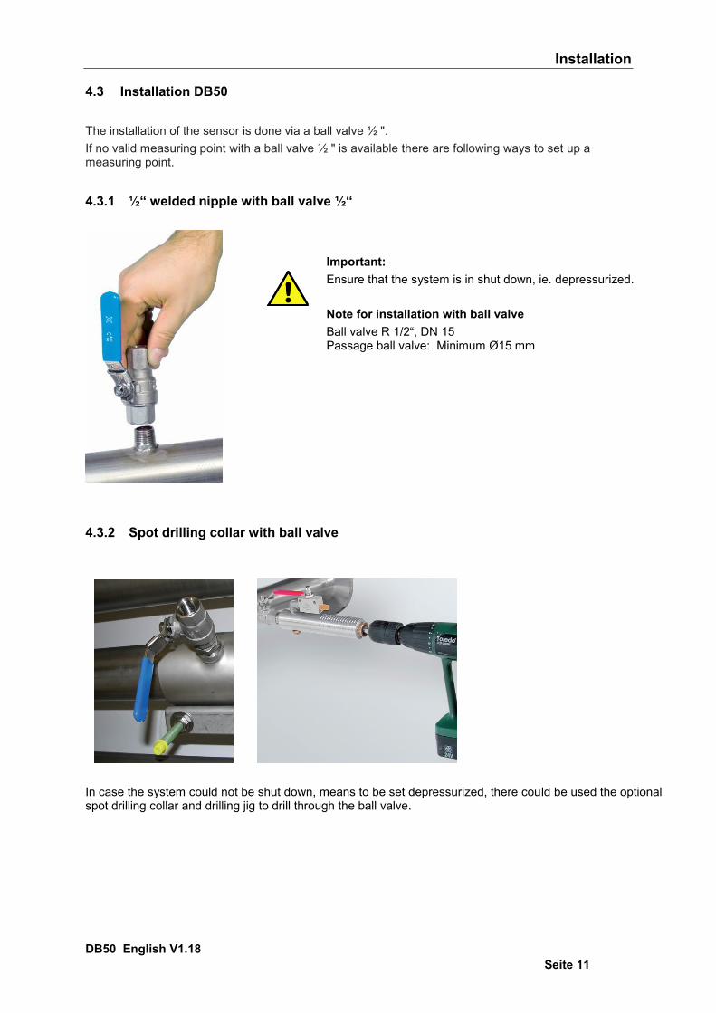
4.3 Installation DB50 The installation of the sensor is done via a ball valve ½ ". If no valid measuring point with a ball valve ½ " is available there are following ways to set up a measuring point.
4.3.1 ½“ welded nipple with ball valve ½“
4.3.2 Spot drilling collar with ball valve
In case the system could not be shut down, means to be set depressurized, there could be used the optionalspot drilling collar and drilling jig to drill through the ball valve.
Important: Ensure that the system is in shut down, ie. depressurized. Note for installation with ball valve Ball valve R 1/2“, DN 15 Passage ball valve: Minimum Ø15 mm
Installation
DB50 English V1.18 Seite 12
4.4 Installation of the Sensor 4.4.1 Mounting DB50 onto the ball valve
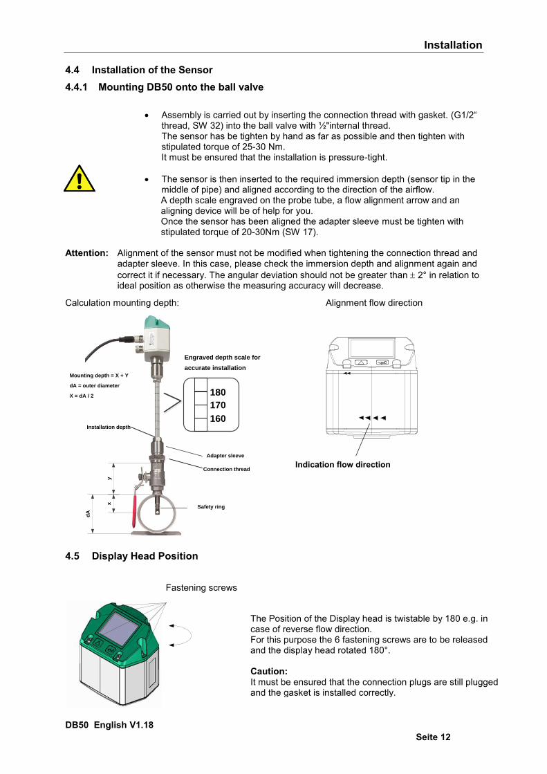
Assembly is carried out by inserting the connection thread with gasket. (G1/2“ thread, SW 32) into the ball valve with ½"internal thread. The sensor has be tighten by hand as far as possible and then tighten with stipulated torque of 25-30 Nm. It must be ensured that the installation is pressure-tight.
The sensor is then inserted to the required immersion depth (sensor tip in the middle of pipe) and aligned according to the direction of the airflow. A depth scale engraved on the probe tube, a flow alignment arrow and an aligning device will be of help for you. Once the sensor has been aligned the adapter sleeve must be tighten with stipulated torque of 20-30Nm (SW 17).
Attention: Alignment of the sensor must not be modified when tightening the connection thread and
adapter sleeve. In this case, please check the immersion depth and alignment again and correct it if necessary. The angular deviation should not be greater than 2° in relation to ideal position as otherwise the measuring accuracy will decrease.
Calculation mounting depth: Alignment flow direction
Mounting depth = X + Y
dA = outer diameter
X = dA / 2
y
dA
x
160
170
180
Installation depth
Engraved depth scale for
accurate installation
Safety ring
Adapter sleeve
Connection thread
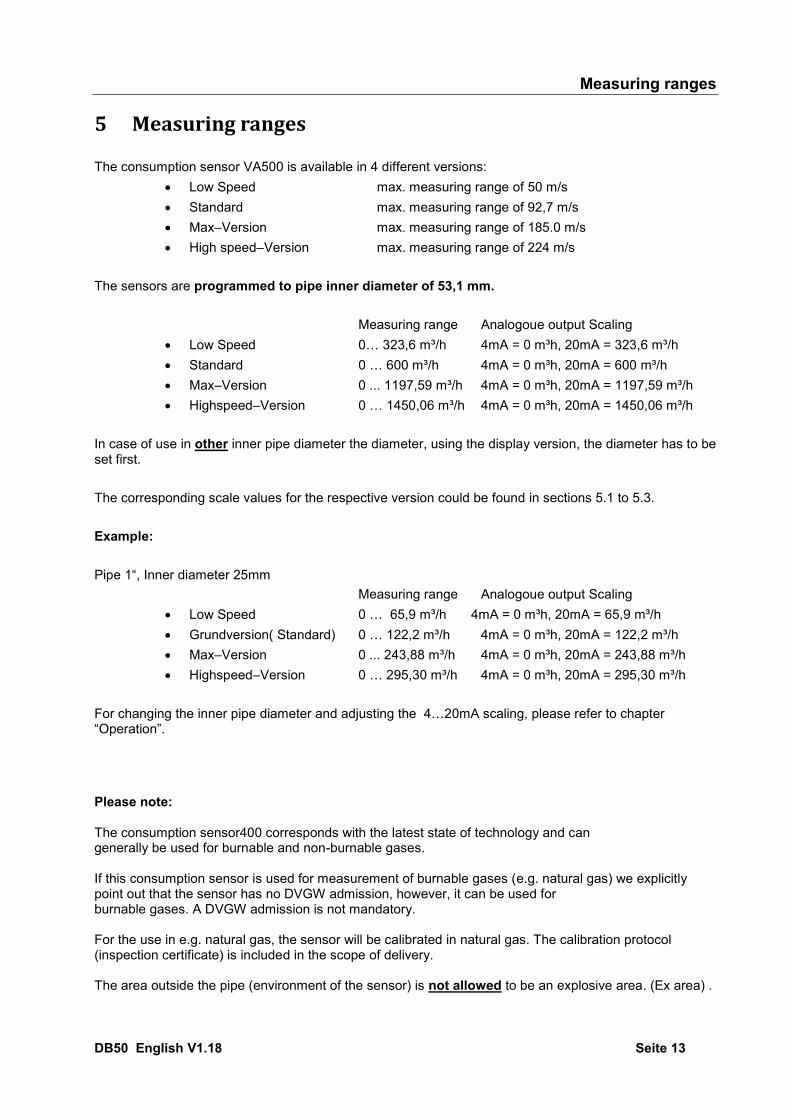
4.5 Display Head Position
The Position of the Display head is twistable by 180 e.g. in case of reverse flow direction. For this purpose the 6 fastening screws are to be released and the display head rotated 180°. Caution: It must be ensured that the connection plugs are still plugged and the gasket is installed correctly.
Fastening screws
Indication flow direction
Measuring ranges
DB50 English V1.18 Seite 13
5 Measuring ranges The consumption sensor VA500 is available in 4 different versions:
Low Speed max. measuring range of 50 m/s Standard max. measuring range of 92,7 m/s Max–Version max. measuring range of 185.0 m/s High speed–Version max. measuring range of 224 m/s
The sensors are programmed to pipe inner diameter of 53,1 mm.
Measuring range Analogoue output Scaling Low Speed 0… 323,6 m³/h 4mA = 0 m³h, 20mA = 323,6 m³/h Standard 0 … 600 m³/h 4mA = 0 m³h, 20mA = 600 m³/h Max–Version 0 ... 1197,59 m³/h 4mA = 0 m³h, 20mA = 1197,59 m³/h Highspeed–Version 0 … 1450,06 m³/h 4mA = 0 m³h, 20mA = 1450,06 m³/h
In case of use in other inner pipe diameter the diameter, using the display version, the diameter has to be set first. The corresponding scale values for the respective version could be found in sections 5.1 to 5.3. Example: Pipe 1“, Inner diameter 25mm
Measuring range Analogoue output Scaling Low Speed 0 … 65,9 m³/h 4mA = 0 m³h, 20mA = 65,9 m³/h Grundversion( Standard) 0 … 122,2 m³/h 4mA = 0 m³h, 20mA = 122,2 m³/h Max–Version 0 ... 243,88 m³/h 4mA = 0 m³h, 20mA = 243,88 m³/h Highspeed–Version 0 … 295,30 m³/h 4mA = 0 m³h, 20mA = 295,30 m³/h
For changing the inner pipe diameter and adjusting the 4…20mA scaling, please refer to chapter “Operation”. Please note: The consumption sensor400 corresponds with the latest state of technology and can generally be used for burnable and non-burnable gases. If this consumption sensor is used for measurement of burnable gases (e.g. natural gas) we explicitly point out that the sensor has no DVGW admission, however, it can be used for burnable gases. A DVGW admission is not mandatory. For the use in e.g. natural gas, the sensor will be calibrated in natural gas. The calibration protocol (inspection certificate) is included in the scope of delivery. The area outside the pipe (environment of the sensor) is not allowed to be an explosive area. (Ex area) .
Measuring ranges
DB50 English V1.18 Seite 14
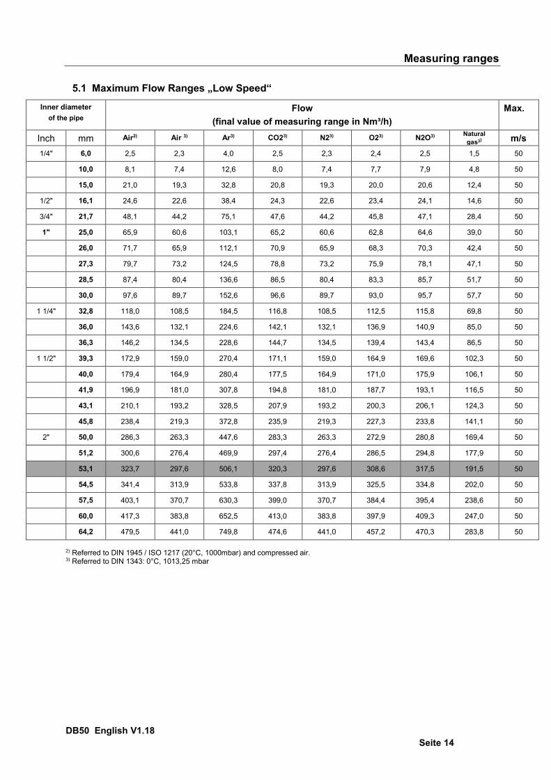
5.1 Maximum Flow Ranges „Low Speed“
Inner diameter of the pipe
Flow (final value of measuring range in Nm³/h)
Max.
Inch mm Air2) Air 3) Ar3) CO23) N23) O23) N2O3) Natural gas3)
Methan m/s
1/4" 6,0 2,5 2,3 4,0 2,5 2,3 2,4 2,5 1,5 50
10,0 8,1 7,4 12,6 8,0 7,4 7,7 7,9 4,8 50
15,0 21,0 19,3 32,8 20,8 19,3 20,0 20,6 12,4 50
1/2" 16,1 24,6 22,6 38,4 24,3 22,6 23,4 24,1 14,6 50
3/4" 21,7 48,1 44,2 75,1 47,6 44,2 45,8 47,1 28,4 50
1" 25,0 65,9 60,6 103,1 65,2 60,6 62,8 64,6 39,0 50
26,0 71,7 65,9 112,1 70,9 65,9 68,3 70,3 42,4 50
27,3 79,7 73,2 124,5 78,8 73,2 75,9 78,1 47,1 50
28,5 87,4 80,4 136,6 86,5 80,4 83,3 85,7 51,7 50
30,0 97,6 89,7 152,6 96,6 89,7 93,0 95,7 57,7 50
1 1/4" 32,8 118,0 108,5 184,5 116,8 108,5 112,5 115,8 69,8 50
36,0 143,6 132,1 224,6 142,1 132,1 136,9 140,9 85,0 50
36,3 146,2 134,5 228,6 144,7 134,5 139,4 143,4 86,5 50
1 1/2" 39,3 172,9 159,0 270,4 171,1 159,0 164,9 169,6 102,3 50
40,0 179,4 164,9 280,4 177,5 164,9 171,0 175,9 106,1 50
41,9 196,9 181,0 307,8 194,8 181,0 187,7 193,1 116,5 50
43,1 210,1 193,2 328,5 207,9 193,2 200,3 206,1 124,3 50
45,8 238,4 219,3 372,8 235,9 219,3 227,3 233,8 141,1 50
2" 50,0 286,3 263,3 447,6 283,3 263,3 272,9 280,8 169,4 50
51,2 300,6 276,4 469,9 297,4 276,4 286,5 294,8 177,9 50
53,1 323,7 297,6 506,1 320,3 297,6 308,6 317,5 191,5 50
54,5 341,4 313,9 533,8 337,8 313,9 325,5 334,8 202,0 50
57,5 403,1 370,7 630,3 399,0 370,7 384,4 395,4 238,6 50
60,0 417,3 383,8 652,5 413,0 383,8 397,9 409,3 247,0 50
64,2 479,5 441,0 749,8 474,6 441,0 457,2 470,3 283,8 50
2) Referred to DIN 1945 / ISO 1217 (20°C, 1000mbar) and compressed air. 3) Referred to DIN 1343: 0°C, 1013,25 mbar
Measuring ranges
DB50 English V1.18 Seite 15
Inner diameter
of the pipe Flow
(final value of measuring range in Nm³/h) Max.
Inch mm Air 2) Air 3) Ar3) CO23) N23) O23) N2O3) Natural gas3)
Methan m/s
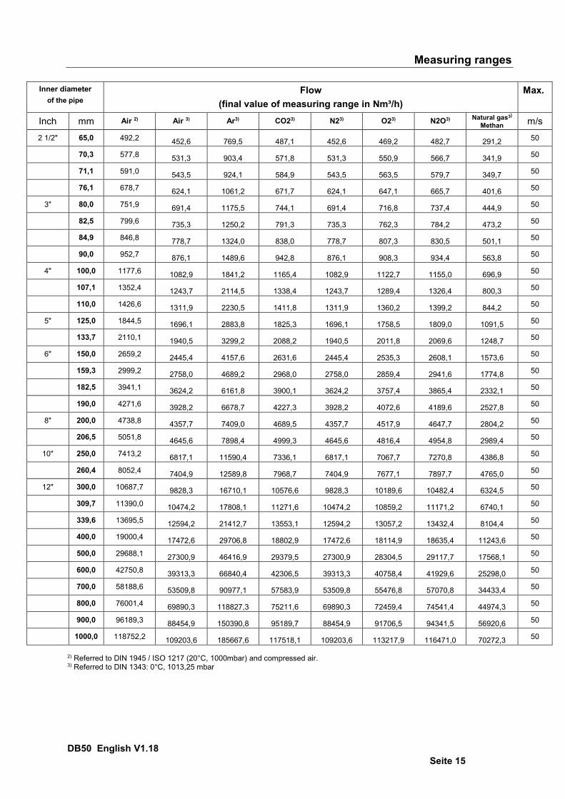
2 1/2" 65,0 492,2 452,6 769,5 487,1 452,6 469,2 482,7 291,2 50
70,3 577,8 531,3 903,4 571,8 531,3 550,9 566,7 341,9 50
71,1 591,0 543,5 924,1 584,9 543,5 563,5 579,7 349,7 50
76,1 678,7 624,1 1061,2 671,7 624,1 647,1 665,7 401,6 50
3" 80,0 751,9 691,4 1175,5 744,1 691,4 716,8 737,4 444,9 50
82,5 799,6 735,3 1250,2 791,3 735,3 762,3 784,2 473,2 50
84,9 846,8 778,7 1324,0 838,0 778,7 807,3 830,5 501,1 50
90,0 952,7 876,1 1489,6 942,8 876,1 908,3 934,4 563,8 50
4" 100,0 1177,6 1082,9 1841,2 1165,4 1082,9 1122,7 1155,0 696,9 50
107,1 1352,4 1243,7 2114,5 1338,4 1243,7 1289,4 1326,4 800,3 50
110,0 1426,6 1311,9 2230,5 1411,8 1311,9 1360,2 1399,2 844,2 50
5" 125,0 1844,5 1696,1 2883,8 1825,3 1696,1 1758,5 1809,0 1091,5 50
133,7 2110,1 1940,5 3299,2 2088,2 1940,5 2011,8 2069,6 1248,7 50
6" 150,0 2659,2 2445,4 4157,6 2631,6 2445,4 2535,3 2608,1 1573,6 50
159,3 2999,2 2758,0 4689,2 2968,0 2758,0 2859,4 2941,6 1774,8 50
182,5 3941,1 3624,2 6161,8 3900,1 3624,2 3757,4 3865,4 2332,1 50
190,0 4271,6 3928,2 6678,7 4227,3 3928,2 4072,6 4189,6 2527,8 50
8" 200,0 4738,8 4357,7 7409,0 4689,5 4357,7 4517,9 4647,7 2804,2 50
206,5 5051,8 4645,6 7898,4 4999,3 4645,6 4816,4 4954,8 2989,4 50
10" 250,0 7413,2 6817,1 11590,4 7336,1 6817,1 7067,7 7270,8 4386,8 50
260,4 8052,4 7404,9 12589,8 7968,7 7404,9 7677,1 7897,7 4765,0 50
12" 300,0 10687,7 9828,3 16710,1 10576,6 9828,3 10189,6 10482,4 6324,5 50
309,7 11390,0 10474,2 17808,1 11271,6 10474,2 10859,2 11171,2 6740,1 50
339,6 13695,5 12594,2 21412,7 13553,1 12594,2 13057,2 13432,4 8104,4 50
400,0 19000,4 17472,6 29706,8 18802,9 17472,6 18114,9 18635,4 11243,6 50
500,0 29688,1 27300,9 46416,9 29379,5 27300,9 28304,5 29117,7 17568,1 50
600,0 42750,8 39313,3 66840,4 42306,5 39313,3 40758,4 41929,6 25298,0 50
700,0 58188,6 53509,8 90977,1 57583,9 53509,8 55476,8 57070,8 34433,4 50
800,0 76001,4 69890,3 118827,3 75211,6 69890,3 72459,4 74541,4 44974,3 50
900,0 96189,3 88454,9 150390,8 95189,7 88454,9 91706,5 94341,5 56920,6 50
1000,0 118752,2 109203,6 185667,6 117518,1 109203,6 113217,9 116471,0 70272,3 50
2) Referred to DIN 1945 / ISO 1217 (20°C, 1000mbar) and compressed air. 3) Referred to DIN 1343: 0°C, 1013,25 mbar
Measuring ranges
DB50 English V1.18 Seite 16
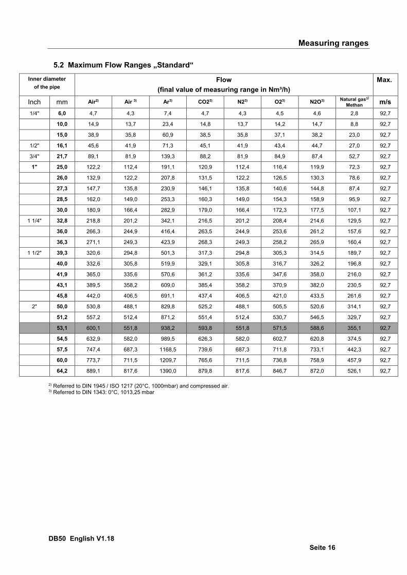
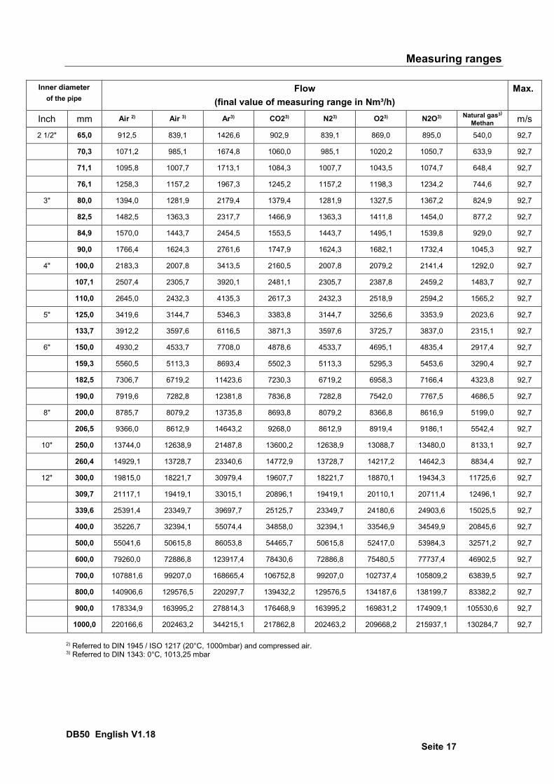
5.2 Maximum Flow Ranges „Standard“
Inner diameter of the pipe
Flow (final value of measuring range in Nm³/h)
Max.
Inch mm Air2) Air 3) Ar3) CO23) N23) O23) N2O3) Natural gas3)
Methan m/s 1/4" 6,0 4,7 4,3 7,4 4,7 4,3 4,5 4,6 2,8 92,7
10,0 14,9 13,7 23,4 14,8 13,7 14,2 14,7 8,8 92,7
15,0 38,9 35,8 60,9 38,5 35,8 37,1 38,2 23,0 92,7
1/2" 16,1 45,6 41,9 71,3 45,1 41,9 43,4 44,7 27,0 92,7
3/4" 21,7 89,1 81,9 139,3 88,2 81,9 84,9 87,4 52,7 92,7
1" 25,0 122,2 112,4 191,1 120,9 112,4 116,4 119,9 72,3 92,7
26,0 132,9 122,2 207,8 131,5 122,2 126,5 130,3 78,6 92,7
27,3 147,7 135,8 230,9 146,1 135,8 140,6 144,8 87,4 92,7
28,5 162,0 149,0 253,3 160,3 149,0 154,3 158,9 95,9 92,7
30,0 180,9 166,4 282,9 179,0 166,4 172,3 177,5 107,1 92,7
1 1/4" 32,8 218,8 201,2 342,1 216,5 201,2 208,4 214,6 129,5 92,7
36,0 266,3 244,9 416,4 263,5 244,9 253,6 261,2 157,6 92,7
36,3 271,1 249,3 423,9 268,3 249,3 258,2 265,9 160,4 92,7
1 1/2" 39,3 320,6 294,8 501,3 317,3 294,8 305,3 314,5 189,7 92,7
40,0 332,6 305,8 519,9 329,1 305,8 316,7 326,2 196,8 92,7
41,9 365,0 335,6 570,6 361,2 335,6 347,6 358,0 216,0 92,7
43,1 389,5 358,2 609,0 385,4 358,2 370,9 382,0 230,5 92,7
45,8 442,0 406,5 691,1 437,4 406,5 421,0 433,5 261,6 92,7
2" 50,0 530,8 488,1 829,8 525,2 488,1 505,5 520,6 314,1 92,7
51,2 557,2 512,4 871,2 551,4 512,4 530,7 546,5 329,7 92,7
53,1 600,1 551,8 938,2 593,8 551,8 571,5 588,6 355,1 92,7
54,5 632,9 582,0 989,5 626,3 582,0 602,7 620,8 374,5 92,7
57,5 747,4 687,3 1168,5 739,6 687,3 711,8 733,1 442,3 92,7
60,0 773,7 711,5 1209,7 765,6 711,5 736,8 758,9 457,9 92,7
64,2 889,1 817,6 1390,0 879,8 817,6 846,7 872,0 526,1 92,7
2) Referred to DIN 1945 / ISO 1217 (20°C, 1000mbar) and compressed air. 3) Referred to DIN 1343: 0°C, 1013,25 mbar
Measuring ranges
DB50 English V1.18 Seite 17
Inner diameter
of the pipe Flow
(final value of measuring range in Nm³/h) Max.
Inch mm Air 2) Air 3) Ar3) CO23) N23) O23) N2O3) Natural gas3)
Methan m/s
2 1/2" 65,0 912,5 839,1 1426,6 902,9 839,1 869,0 895,0 540,0 92,7
70,3 1071,2 985,1 1674,8 1060,0 985,1 1020,2 1050,7 633,9 92,7
71,1 1095,8 1007,7 1713,1 1084,3 1007,7 1043,5 1074,7 648,4 92,7
76,1 1258,3 1157,2 1967,3 1245,2 1157,2 1198,3 1234,2 744,6 92,7
3" 80,0 1394,0 1281,9 2179,4 1379,4 1281,9 1327,5 1367,2 824,9 92,7
82,5 1482,5 1363,3 2317,7 1466,9 1363,3 1411,8 1454,0 877,2 92,7
84,9 1570,0 1443,7 2454,5 1553,5 1443,7 1495,1 1539,8 929,0 92,7
90,0 1766,4 1624,3 2761,6 1747,9 1624,3 1682,1 1732,4 1045,3 92,7
4" 100,0 2183,3 2007,8 3413,5 2160,5 2007,8 2079,2 2141,4 1292,0 92,7
107,1 2507,4 2305,7 3920,1 2481,1 2305,7 2387,8 2459,2 1483,7 92,7
110,0 2645,0 2432,3 4135,3 2617,3 2432,3 2518,9 2594,2 1565,2 92,7
5" 125,0 3419,6 3144,7 5346,3 3383,8 3144,7 3256,6 3353,9 2023,6 92,7
133,7 3912,2 3597,6 6116,5 3871,3 3597,6 3725,7 3837,0 2315,1 92,7
6" 150,0 4930,2 4533,7 7708,0 4878,6 4533,7 4695,1 4835,4 2917,4 92,7
159,3 5560,5 5113,3 8693,4 5502,3 5113,3 5295,3 5453,6 3290,4 92,7
182,5 7306,7 6719,2 11423,6 7230,3 6719,2 6958,3 7166,4 4323,8 92,7
190,0 7919,6 7282,8 12381,8 7836,8 7282,8 7542,0 7767,5 4686,5 92,7
8" 200,0 8785,7 8079,2 13735,8 8693,8 8079,2 8366,8 8616,9 5199,0 92,7
206,5 9366,0 8612,9 14643,2 9268,0 8612,9 8919,4 9186,1 5542,4 92,7
10" 250,0 13744,0 12638,9 21487,8 13600,2 12638,9 13088,7 13480,0 8133,1 92,7
260,4 14929,1 13728,7 23340,6 14772,9 13728,7 14217,2 14642,3 8834,4 92,7
12" 300,0 19815,0 18221,7 30979,4 19607,7 18221,7 18870,1 19434,3 11725,6 92,7
309,7 21117,1 19419,1 33015,1 20896,1 19419,1 20110,1 20711,4 12496,1 92,7
339,6 25391,4 23349,7 39697,7 25125,7 23349,7 24180,6 24903,6 15025,5 92,7
400,0 35226,7 32394,1 55074,4 34858,0 32394,1 33546,9 34549,9 20845,6 92,7
500,0 55041,6 50615,8 86053,8 54465,7 50615,8 52417,0 53984,3 32571,2 92,7
600,0 79260,0 72886,8 123917,4 78430,6 72886,8 75480,5 77737,4 46902,5 92,7
700,0 107881,6 99207,0 168665,4 106752,8 99207,0 102737,4 105809,2 63839,5 92,7
800,0 140906,6 129576,5 220297,7 139432,2 129576,5 134187,6 138199,7 83382,2 92,7
900,0 178334,9 163995,2 278814,3 176468,9 163995,2 169831,2 174909,1 105530,6 92,7
1000,0 220166,6 202463,2 344215,1 217862,8 202463,2 209668,2 215937,1 130284,7 92,7
2) Referred to DIN 1945 / ISO 1217 (20°C, 1000mbar) and compressed air. 3) Referred to DIN 1343: 0°C, 1013,25 mbar
Measuring ranges
DB50 English V1.18 Seite 18
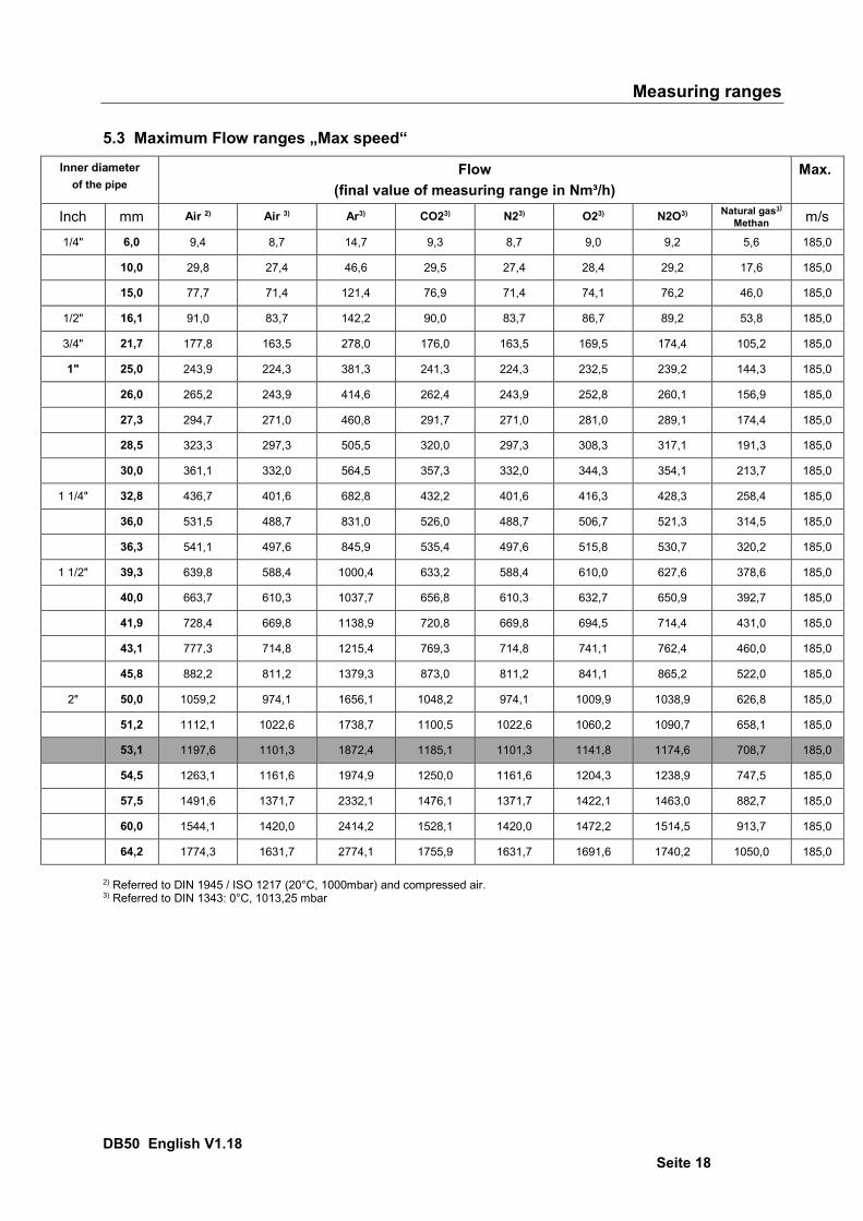
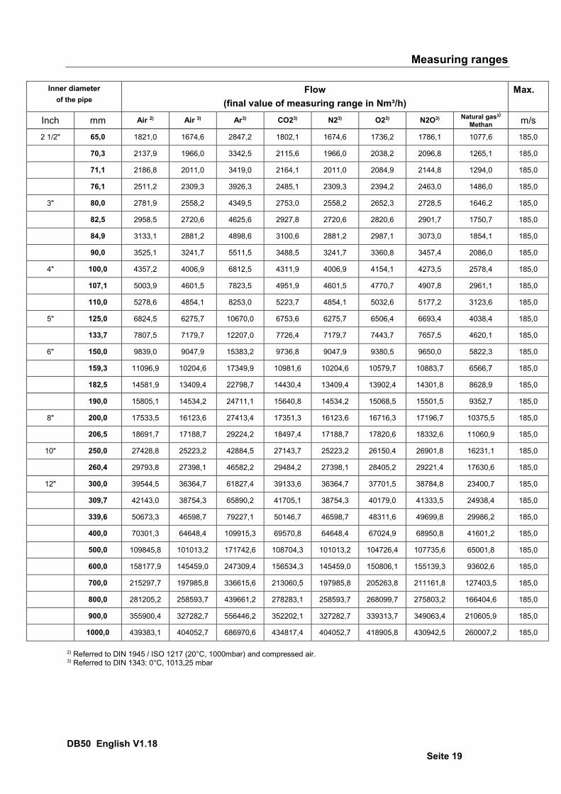
5.3 Maximum Flow ranges „Max speed“
Inner diameter of the pipe
Flow (final value of measuring range in Nm³/h)
Max.
Inch mm Air 2) Air 3) Ar3) CO23) N23) O23) N2O3) Natural gas3)
Methan m/s
1/4" 6,0 9,4 8,7 14,7 9,3 8,7 9,0 9,2 5,6 185,0
10,0 29,8 27,4 46,6 29,5 27,4 28,4 29,2 17,6 185,0
15,0 77,7 71,4 121,4 76,9 71,4 74,1 76,2 46,0 185,0
1/2" 16,1 91,0 83,7 142,2 90,0 83,7 86,7 89,2 53,8 185,0
3/4" 21,7 177,8 163,5 278,0 176,0 163,5 169,5 174,4 105,2 185,0
1" 25,0 243,9 224,3 381,3 241,3 224,3 232,5 239,2 144,3 185,0
26,0 265,2 243,9 414,6 262,4 243,9 252,8 260,1 156,9 185,0
27,3 294,7 271,0 460,8 291,7 271,0 281,0 289,1 174,4 185,0
28,5 323,3 297,3 505,5 320,0 297,3 308,3 317,1 191,3 185,0
30,0 361,1 332,0 564,5 357,3 332,0 344,3 354,1 213,7 185,0
1 1/4" 32,8 436,7 401,6 682,8 432,2 401,6 416,3 428,3 258,4 185,0
36,0 531,5 488,7 831,0 526,0 488,7 506,7 521,3 314,5 185,0
36,3 541,1 497,6 845,9 535,4 497,6 515,8 530,7 320,2 185,0
1 1/2" 39,3 639,8 588,4 1000,4 633,2 588,4 610,0 627,6 378,6 185,0
40,0 663,7 610,3 1037,7 656,8 610,3 632,7 650,9 392,7 185,0
41,9 728,4 669,8 1138,9 720,8 669,8 694,5 714,4 431,0 185,0
43,1 777,3 714,8 1215,4 769,3 714,8 741,1 762,4 460,0 185,0
45,8 882,2 811,2 1379,3 873,0 811,2 841,1 865,2 522,0 185,0
2" 50,0 1059,2 974,1 1656,1 1048,2 974,1 1009,9 1038,9 626,8 185,0
51,2 1112,1 1022,6 1738,7 1100,5 1022,6 1060,2 1090,7 658,1 185,0
53,1 1197,6 1101,3 1872,4 1185,1 1101,3 1141,8 1174,6 708,7 185,0
54,5 1263,1 1161,6 1974,9 1250,0 1161,6 1204,3 1238,9 747,5 185,0
57,5 1491,6 1371,7 2332,1 1476,1 1371,7 1422,1 1463,0 882,7 185,0
60,0 1544,1 1420,0 2414,2 1528,1 1420,0 1472,2 1514,5 913,7 185,0
64,2 1774,3 1631,7 2774,1 1755,9 1631,7 1691,6 1740,2 1050,0 185,0
2) Referred to DIN 1945 / ISO 1217 (20°C, 1000mbar) and compressed air. 3) Referred to DIN 1343: 0°C, 1013,25 mbar
Measuring ranges
DB50 English V1.18 Seite 19
Inner diameter
of the pipe Flow
(final value of measuring range in Nm³/h) Max.
Inch mm Air 2) Air 3) Ar3) CO23) N23) O23) N2O3) Natural gas3)
Methan m/s
2 1/2" 65,0 1821,0 1674,6 2847,2 1802,1 1674,6 1736,2 1786,1 1077,6 185,0
70,3 2137,9 1966,0 3342,5 2115,6 1966,0 2038,2 2096,8 1265,1 185,0
71,1 2186,8 2011,0 3419,0 2164,1 2011,0 2084,9 2144,8 1294,0 185,0
76,1 2511,2 2309,3 3926,3 2485,1 2309,3 2394,2 2463,0 1486,0 185,0
3" 80,0 2781,9 2558,2 4349,5 2753,0 2558,2 2652,3 2728,5 1646,2 185,0
82,5 2958,5 2720,6 4625,6 2927,8 2720,6 2820,6 2901,7 1750,7 185,0
84,9 3133,1 2881,2 4898,6 3100,6 2881,2 2987,1 3073,0 1854,1 185,0
90,0 3525,1 3241,7 5511,5 3488,5 3241,7 3360,8 3457,4 2086,0 185,0
4" 100,0 4357,2 4006,9 6812,5 4311,9 4006,9 4154,1 4273,5 2578,4 185,0
107,1 5003,9 4601,5 7823,5 4951,9 4601,5 4770,7 4907,8 2961,1 185,0
110,0 5278,6 4854,1 8253,0 5223,7 4854,1 5032,6 5177,2 3123,6 185,0
5" 125,0 6824,5 6275,7 10670,0 6753,6 6275,7 6506,4 6693,4 4038,4 185,0
133,7 7807,5 7179,7 12207,0 7726,4 7179,7 7443,7 7657,5 4620,1 185,0
6" 150,0 9839,0 9047,9 15383,2 9736,8 9047,9 9380,5 9650,0 5822,3 185,0
159,3 11096,9 10204,6 17349,9 10981,6 10204,6 10579,7 10883,7 6566,7 185,0
182,5 14581,9 13409,4 22798,7 14430,4 13409,4 13902,4 14301,8 8628,9 185,0
190,0 15805,1 14534,2 24711,1 15640,8 14534,2 15068,5 15501,5 9352,7 185,0
8" 200,0 17533,5 16123,6 27413,4 17351,3 16123,6 16716,3 17196,7 10375,5 185,0
206,5 18691,7 17188,7 29224,2 18497,4 17188,7 17820,6 18332,6 11060,9 185,0
10" 250,0 27428,8 25223,2 42884,5 27143,7 25223,2 26150,4 26901,8 16231,1 185,0
260,4 29793,8 27398,1 46582,2 29484,2 27398,1 28405,2 29221,4 17630,6 185,0
12" 300,0 39544,5 36364,7 61827,4 39133,6 36364,7 37701,5 38784,8 23400,7 185,0
309,7 42143,0 38754,3 65890,2 41705,1 38754,3 40179,0 41333,5 24938,4 185,0
339,6 50673,3 46598,7 79227,1 50146,7 46598,7 48311,6 49699,8 29986,2 185,0
400,0 70301,3 64648,4 109915,3 69570,8 64648,4 67024,9 68950,8 41601,2 185,0
500,0 109845,8 101013,2 171742,6 108704,3 101013,2 104726,4 107735,6 65001,8 185,0
600,0 158177,9 145459,0 247309,4 156534,3 145459,0 150806,1 155139,3 93602,6 185,0
700,0 215297,7 197985,8 336615,6 213060,5 197985,8 205263,8 211161,8 127403,5 185,0
800,0 281205,2 258593,7 439661,2 278283,1 258593,7 268099,7 275803,2 166404,6 185,0
900,0 355900,4 327282,7 556446,2 352202,1 327282,7 339313,7 349063,4 210605,9 185,0
1000,0 439383,1 404052,7 686970,6 434817,4 404052,7 418905,8 430942,5 260007,2 185,0
2) Referred to DIN 1945 / ISO 1217 (20°C, 1000mbar) and compressed air. 3) Referred to DIN 1343: 0°C, 1013,25 mbar

Measuring ranges
DB50 English V1.18 Seite 20
5.4 Maximum Flow ranges „High speed“ Inner diameter
of the pipe Flow
(final value of measuring range in Nm³/h) Max.
Inch mm Air 2) Air 3) Ar3) CO23) N23) O23) N2O3) Natural gas3)
Methan m/s
1/4" 6,0 11,4 10,5 17,8 11,3 10,5 10,9 11,2 6,7 224,0
10,0 36,1 33,2 56,4 35,7 33,2 34,4 35,4 21,4 224,0
15,0 94,1 86,5 147,0 93,1 86,5 89,7 92,2 55,7 224,0
1/2" 16,1 110,2 101,3 172,2 109,0 101,3 105,0 108,0 65,2 224,0
3/4" 21,7 215,3 198,0 336,7 213,1 198,0 205,3 211,2 127,4 224,0
1" 25,0 295,3 271,6 461,7 292,2 271,6 281,5 289,6 174,7 224,0
26,0 321,1 295,3 502,0 317,8 295,3 306,1 314,9 190,0 224,0
27,3 356,9 328,2 557,9 353,1 328,2 340,2 350,0 211,2 224,0
28,5 391,5 360,0 612,1 387,4 360,0 373,2 384,0 231,7 224,0
30,0 437,2 402,0 683,6 432,7 402,0 416,8 428,8 258,7 224,0
1 1/4" 32,8 528,7 486,2 826,7 523,3 486,2 504,1 518,6 312,9 224,0
36,0 643,5 591,8 1006,1 636,8 591,8 613,5 631,2 380,8 224,0
36,3 655,1 602,4 1024,3 648,3 602,4 624,6 642,5 387,7 224,0
1 1/2" 39,3 774,7 712,4 1211,3 766,7 712,4 738,6 759,8 458,5 224,0
40,0 803,6 739,0 1256,4 795,2 739,0 766,1 788,2 475,5 224,0
41,9 882,0 811,0 1378,9 872,8 811,0 840,9 865,0 521,9 224,0
43,1 941,2 865,5 1471,6 931,4 865,5 897,3 923,1 557,0 224,0
45,8 1068,1 982,2 1670,0 1057,0 982,3 1018,4 1047,6 632,1 224,0
2" 50,0 1282,5 1179,4 2005,2 1269,2 1179,4 1222,8 1257,9 758,9 224,0
51,2 1346,5 1238,2 2105,2 1332,5 1238,2 1283,7 1320,6 796,8 224,0
53,1 1450,1 1333,5 2267,1 1435,0 1333,5 1382,5 1422,2 858,1 224,0
54,5 1529,4 1406,4 2391,2 1513,5 1406,4 1458,1 1500,0 905,0 224,0
57,5 1806,1 1660,8 2823,8 1787,3 1660,8 1721,9 1771,4 1068,8 224,0
60,0 1869,6 1719,3 2923,2 1850,2 1719,3 1782,5 1833,7 1106,4 224,0
64,2 2148,4 1975,6 3359,0 2126,1 1975,6 2048,3 2107,1 1271,3 224,0
2) Referred to DIN 1945 / ISO 1217 (20°C, 1000mbar) and compressed air. 3) Referred to DIN 1343: 0°C, 1013,25 mbar

Measuring ranges
DB50 English V1.18 Seite 21
Inner diameter
of the pipe Flow
(final value of measuring range in Nm³/h) Max.
Inch mm Air 2) Air 3) Ar3) CO23) N23) O23) N2O3) Natural gas3)
Methan m/s
2 1/2" 65,0 2204,9 2027,6 3447,4 2182,0 2027,6 2102,2 2162,6 1304,8 224,0
70,3 2588,6 2380,4 4047,2 2561,7 2380,4 2467,9 2538,8 1531,8 224,0
71,1 2647,8 2434,9 4139,8 2620,3 2434,9 2524,4 2596,9 1566,8 224,0
76,1 3040,6 2796,1 4754,0 3009,0 2796,1 2898,9 2982,2 1799,3 224,0
3" 80,0 3368,4 3097,5 5266,4 3333,4 3097,5 3211,4 3303,7 1993,3 224,0
82,5 3582,2 3294,2 5600,7 3545,0 3294,2 3415,2 3513,4 2119,8 224,0
84,9 3793,6 3488,6 5931,3 3754,2 3488,6 3616,8 3720,8 2244,9 224,0
90,0 4268,2 3925,0 6673,3 4223,9 3925,0 4069,3 4186,2 2525,8 224,0
4" 100,0 5275,8 4851,5 8248,6 5220,9 4851,6 5029,9 5174,4 3122,0 224,0
107,1 6058,8 5571,6 9472,8 5995,8 5571,6 5776,4 5942,4 3585,3 224,0
110,0 6391,3 5877,4 9992,8 6324,9 5877,4 6093,5 6268,6 3782,1 224,0
5" 125,0 8263,2 7598,7 12919,4 8177,3 7598,8 7878,1 8104,4 4889,8 224,0
133,7 9453,4 8693,3 14780,3 9355,2 8693,3 9012,9 9271,8 5594,1 224,0
6" 150,0 11913,2 10955,3 18626,2 11789,4 10955,3 11358,0 11684,4 7049,7 224,0
159,3 13436,3 12355,9 21007,4 13296,6 12355,9 12810,1 13178,1 7951,0 224,0
182,5 17656,0 16236,3 27604,9 17472,5 16236,3 16833,1 17316,8 10448,0 224,0
190,0 19137,0 17598,2 29920,4 18938,1 17598,2 18245,1 18769,3 11324,4 224,0
8" 200,0 21229,7 19522,7 33192,4 21009,1 19522,7 20240,3 20821,9 12562,8 224,0
206,5 22632,1 20812,3 35385,0 22396,9 20812,3 21577,3 22197,3 13392,6 224,0
10" 250,0 33211,0 30540,6 51925,1 32865,9 30540,6 31663,2 32573,0 19652,8 224,0
260,4 36074,6 33173,9 56402,2 35699,7 33174,0 34393,4 35381,6 21347,3 224,0
12" 300,0 47880,9 44030,8 74861,2 47383,3 44030,9 45649,4 46961,1 28333,8 224,0
309,7 51027,2 46924,2 79780,5 50497,0 46924,3 48649,1 50047,0 30195,6 224,0
339,6 61355,7 56422,1 95929,0 60718,1 56422,3 58496,2 60177,1 36307,5 224,0
400,0 85121,6 78277,0 133086,6 84237,0 78277,2 81154,5 83486,4 50371,1 224,0
500,0 133002,5 122307,8 207947,8 131620,4 122308,1 126803,9 130447,5 78704,9 224,0
600,0 191523,6 176123,3 299444,9 189533,3 176123,7 182597,6 187844,3 113335,0 224,0
700,0 260684,8 239723,3 407577,7 257975,9 239724,0 248535,6 255677,0 154261,5 224,0
800,0 340486,3 313108,0 532346,4 336948,1 313108,8 324618,0 333945,5 201484,4 224,0
900,0 430928,0 396277,3 673750,9 426450,0 396278,4 410844,6 422649,7 255003,8 224,0
1000,0 532009,9 489231,3 831791,3 526481,5 489232,6 507215,6 521789,8 314819,5 224,0
2) Referred to DIN 1945 / ISO 1217 (20°C, 1000mbar) and compressed air. 3) Referred to DIN 1343: 0°C, 1013,25 mbar
Dimension
DB50 English V1.18 Seite 22
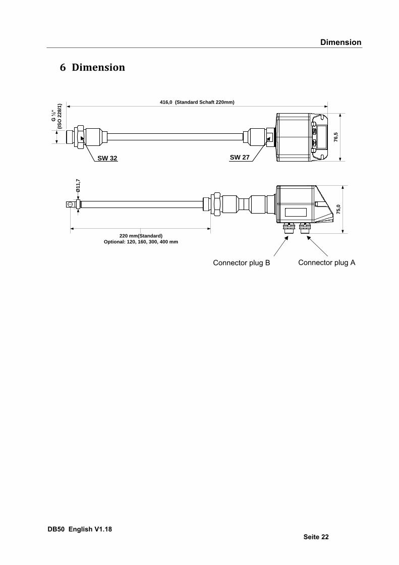
6 Dimension
416,0 (Standard Schaft 220mm)
76
,5
G ½
“
(IS
O 2
28
/1)
SW 32 SW 27
75
,0
220 mm(Standard)
Optional: 120, 160, 300, 400 mm
Ø1
1,7
Connector plug A Connector plug B
Electrical wiring
DB50 English V1.18 Seite 23
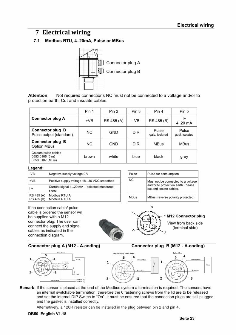
7 Electrical wiring 7.1 Modbus RTU, 4..20mA, Pulse or MBus
Attention: Not required connections NC must not be connected to a voltage and/or to protection earth. Cut and insulate cables.
Pin 1 Pin 2 Pin 3 Pin 4 Pin 5
Connector plug A +VB RS 485 (A) -VB RS 485 (B) I+ 4..20 mA
Connector plug B Pulse output (standard) NC GND DIR Pulse
galv. isolated Pulse
gavl. isolated
Connector plug B Option MBus
NC GND DIR MBus MBus
Colours pulse cables 0553 0106 (5 m) 0553.0107 (10 m)
brown white blue black grey
Legend: -VB Negative supply voltage 0 V Pulse Pulse for consumption
+VB Positive supply voltage 18...36 VDC smoothed NC Must not be connected to a voltage and/or to protection earth. Please cut and isolate cables. I + Current signal 4...20 mA – selected measured
signal
RS 485 (A) RS 485 (B)
Modbus RTU A Modbus RTU A MBus MBus (reverse polarity protected)
If no connection cable/ pulse cable is ordered the sensor will be supplied with a M12 connector plug. The user can connect the supply and signal cables as indicated in the connection diagram. .
M12 Connector plug
View from back side (terminal side)
Connector plug A (M12 - A-coding) Connector plug B (M12 - A-coding)
3
4
5
1
2
+ VB
- VB
4 … 20mA
+ -Grau / Grey
Blau / Blue
Weiss / White
Schwarz / Black
Modbus (B)Modbus (A)
Braun / Brown
Remark: If the sensor is placed at the end of the Modbus system a termination is required. The sensors have
an internal switchable termination, therefore the 6 fastening screws from the lid are to be released and set the internal DIP Switch to “On”. It must be ensured that the connection plugs are still plugged and the gasket is installed correctly.
Alternatively, a 120R resistor can be installed in the plug between pin 2 and pin 4.
3
45
1
2
Grau / Grey
Schwarz / Black
Impulsausgang / Pulse output
3
451
2
Grau / Grey
Schwarz / Black
MBus
Option MBus
Connector plug A Connector plug B

Electrical wiring
DB50 English V1.18 Seite 24
7.2 Ethernet (optional PoE) Connector plug B Connection cable M12 x-coded 8 pole M12 x-coded to RJ45
Data LINES: 1,2 und 3,4 PoE LINES: 5,6 und 7,8
2
81
3
5 4
6
7
M12 x 1
Connection cable: Cat 6. *PoE: Power over Ethernet
- Connector plug B (M12 X-coded 8 pole)
- Connector plug A
Operation
DB50 English V1.18 Seite 25
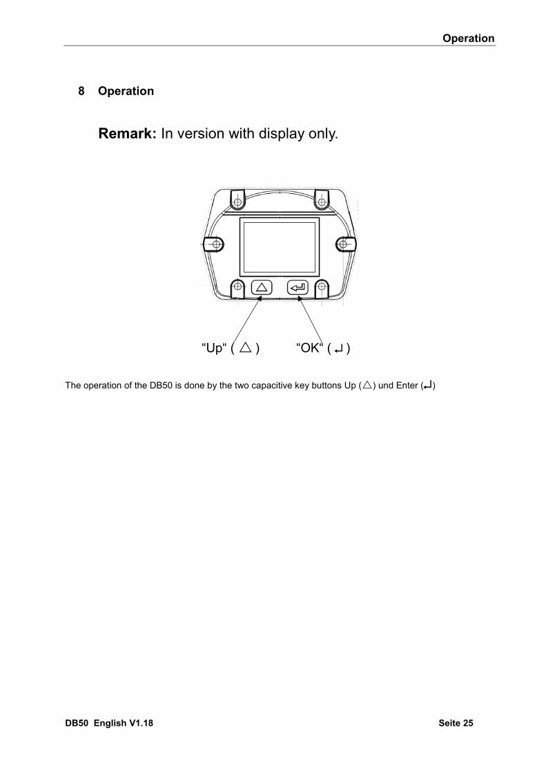
8 Operation
Remark: In version with display only.
“Up“ ( ) “OK“ ( )
The operation of the DB50 is done by the two capacitive key buttons Up () und Enter ()

^ Operation
DB50 English V1.18 Seite 26
8.1 Initialization
8.2 Main menu
HW VersionPage-No.
Gas /
Status Info
SW VersionModbus ID
*** ***
Switching to pages 2-4 or back by pressing key „ “
*** ***
391.23
391
1 minutes
410,34
1 minute
91,3282.46
AV-Time ( Period for average value calculation) could be changed under Sensor Setup.-Advanced– AV-Time
After switching on the DB50, the initialized screen is displayed followed by the main menu.

^ Operation
DB50 English V1.18 Seite 27
8.3 Settings The settings menu could accessed by pressing the key „OK“. But the access to the settings menu is password protected.
Selection of a menu item or to change a value is done with the key „ “, a final move to the chosen menu item or takeover of the value change needs the confirmation by pressing the key „OK“
Factory settings for password at the time of delivery: 0000 (4 times zero). If required the password could be changed at Setup–User setup-Password. .

^ Operation
DB50 English V1.18 Seite 28
8.3.1 Sensor Setup Setup Sensor Setup
53.1 mm
8.3.1.1 Input / change tube diameter
Settings Sensor Setup Diameter
.
For changes, first select the menu item with key „ “ and then confirm it with “OK“.
In order to change, e.g. the unit, first select by pressing key „ “ the field “Units” and then key “OK”. Select with the key „ “ the correct unit and then confirm selection by pressing 2x „OK“. Entering / changing the diameter via button „“ , select the respective position and activate the position with the "OK" button. By pressing „“ the position value is incremented by 1. Complete with "OK" and activate next number position. Confirm entry by pressing „OK“.
^ Operation
DB50 English V1.18 Seite 29
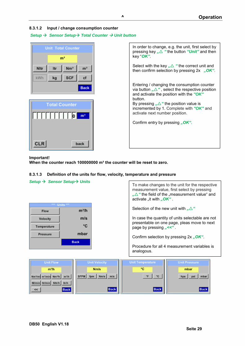
8.3.1.2 Input / change consumption counter
Setup Sensor Setup Total Counter Unit button
Important! When the counter reach 100000000 m³ the counter will be reset to zero.
8.3.1.3 Definition of the units for flow, velocity, temperature and pressure
Setup Sensor Setup Units
In order to change, e.g. the unit, first select by pressing key „ “ the button “Unit” and then key “OK”. Select with the key „ “ the correct unit and then confirm selection by pressing 2x „OK“. Entering / changing the consumption counter via button „“ , select the respective position and activate the position with the "OK" button. By pressing „“ the position value is incremented by 1. Complete with "OK" and activate next number position. Confirm entry by pressing „OK“.
To make changes to the unit for the respective measurement value, first select by pressing „“ the field of the „measurement value“ and activate „it with „OK“ . Selection of the new unit with „“ In case the quantity of units selectable are not presentable on one page, pleas move to next page by pressing „<<“ . Confirm selection by pressing 2x „OK“. Procedure for all 4 measurement variables is analogous.

^ Operation
DB50 English V1.18 Seite 30
8.3.1.4 Definition of the reference conditions
Here can be defined the desired measured media reference conditions for pressure and temperature and times for the filter and averaging.
Factory presetting for reference temperature and reference pressure are 20 °C, 1000 hPa All volume flow values (m³/h) and consumption values indicated in the display are
related to 20 °C and 1000 hPa (according to ISO 1217 intake condition) Alternatively 0 °C and 1013 hPa (=standard cubic meter) can also be entered as a reference. Do not enter the operation pressure or the operation temperature under reference
conditions! Setup Sensor Setup Advanced
Setup Sensor Setup Advanced Ref.Pref
Setup Sensor Setup Advanced Ref.Temp
Setup Sensor Setup Advanced Filtertime
To make changes, first select a menu with button „“ and confirm selection by pressing „OK“ .
In order to change, e.g. the unit, first select by pressing key „ “ the field “Units” and then key “OK”. Select with the key „ “ the correct unit and then confirm selection by pressing 2x „OK“. Input / change of the value by selecting the respective position with button „“and entering by pressing button „OK“ . By pressing „“ the position value is incremented by 1. Complete with "OK" and activate next number position. Procedure for changing the reference temperature is the same. Under point "Filtertime" together with the appropriate "Filter Grade" an attenuation can be defined. Input values of 0 -10000 in [ms] are possible.
^ Operation
DB50 English V1.18 Seite 31
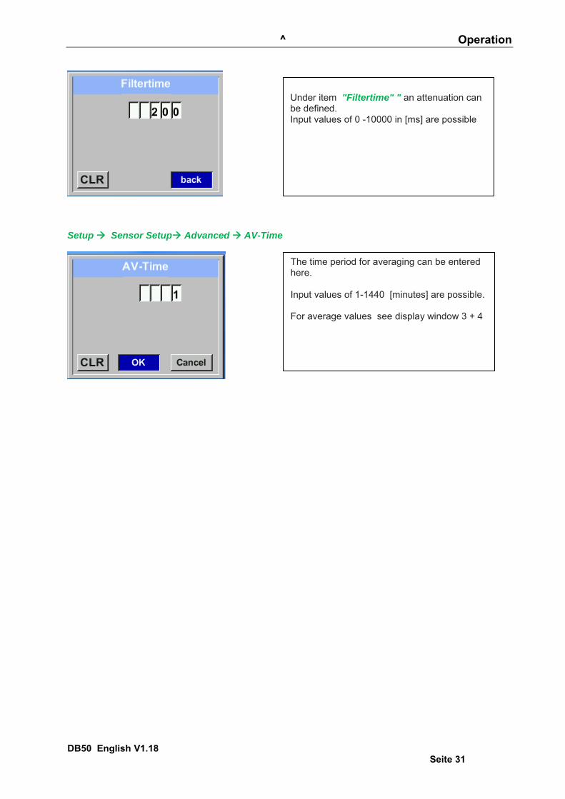
Setup Sensor Setup Advanced AV-Time
Under item "Filtertime" " an attenuation can be defined. Input values of 0 -10000 in [ms] are possible
The time period for averaging can be entered here. Input values of 1-1440 [minutes] are possible. For average values see display window 3 + 4
^ Operation
DB50 English V1.18 Seite 32
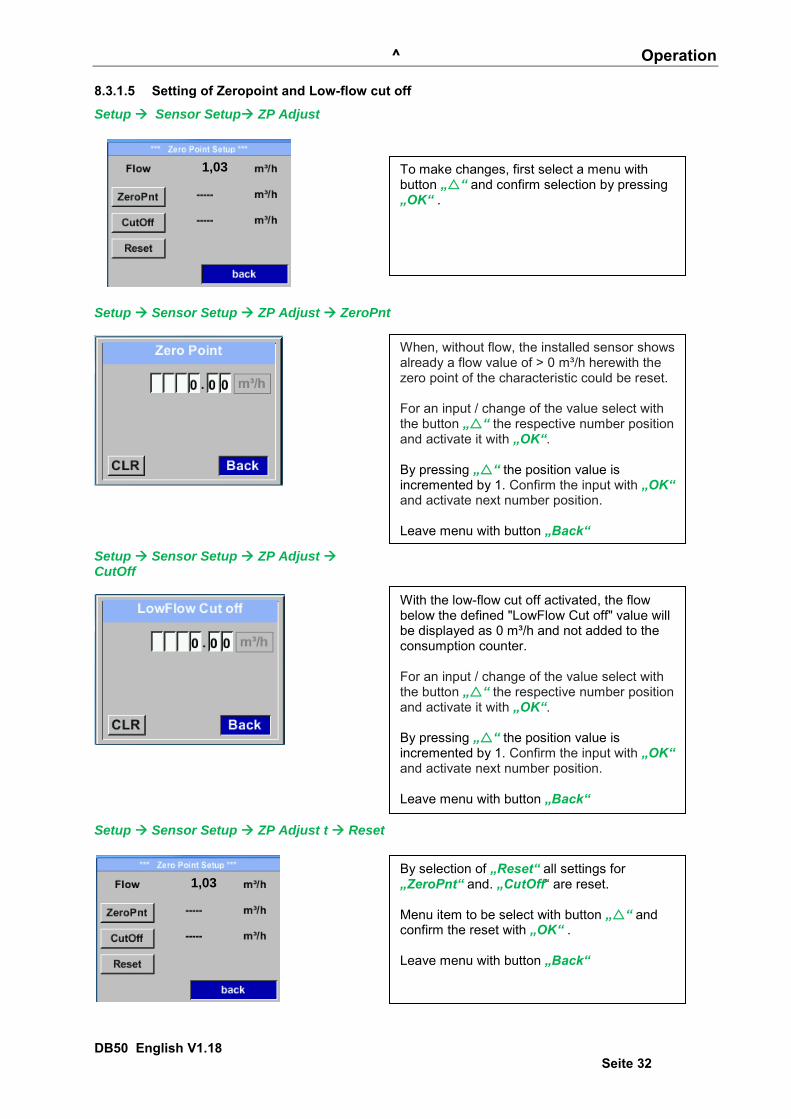
8.3.1.5 Setting of Zeropoint and Low-flow cut off
Setup Sensor Setup ZP Adjust
1,03
Setup Sensor Setup ZP Adjust ZeroPnt
Setup Sensor Setup ZP Adjust CutOff
Setup Sensor Setup ZP Adjust t Reset
1,03
To make changes, first select a menu with button „“ and confirm selection by pressing „OK“ .
When, without flow, the installed sensor shows already a flow value of > 0 m³/h herewith the zero point of the characteristic could be reset. For an input / change of the value select with the button „“ the respective number position and activate it with „OK“. By pressing „“ the position value is incremented by 1. Confirm the input with „OK“ and activate next number position. Leave menu with button „Back“ Menüpunkt mit Taste „“ anwählen und anschließend mit Taste „OK“ auswählen With the low-flow cut off activated, the flow below the defined "LowFlow Cut off" value will be displayed as 0 m³/h and not added to the consumption counter. For an input / change of the value select with the button „“ the respective number position and activate it with „OK“. By pressing „“ the position value is incremented by 1. Confirm the input with „OK“ and activate next number position. Leave menu with button „Back“
By selection of „Reset“ all settings for „ZeroPnt“ and. „CutOff“ are reset. Menu item to be select with button „“ and confirm the reset with „OK“ . Leave menu with button „Back“

^ Operation
DB50 English V1.18 Seite 33
8.3.2 Modbus Settings 8.3.2.1 Modbus RTU Setup
The Flow sensors DB50 comes with a Modbus RTU Interface. Before commissioning the sensor the communication parameters
Modbus ID, Baudrate, Parity und Stop bit must be set in order to ensure the communication with the Modbus master. Settings Modbus Setup
Default values out of factory: Modbus ID: 1
Baud rate: 19200 Stopbit: 1 Parity: even Byte Order: ABCD
Remark: If the sensor is placed at the end of the Modbus system a termination is required. The sensors have an internal switchable termination, therefore the 6 fastening screws from the lid are to be released and set the internal DIP Switch to “On”.
Alternatively, a 120R resistor can be installed in the plug between pin 2 and pin 4. It must be ensured that the connection plugs are still plugged and the gasket is installed correctly, see also chapter 4.5.
For changes, e.g. the sensor ID, first select by pressing key „“ the field “ID” and then key “OK”. Select the desired position by pressing the ">" and select with "OK" button. Change values by pressing the „“ values takeover by pressing "OK". Inputs for baudrate, stopbit and parity is done analogue. By means of the button "Byte Order" it is possible to change the data format (Word Order). Possible formats are "ABCD" (Little Endian) and "CDAB" (Middle Endian) Saving the changes by pressing "Save", therefore select it with key „“ and then confirm it with "OK". To set back to default values please press button “Set to Default”
^ Operation
DB50 English V1.18 Seite 34
8.3.2.2 Modbus TCP (Optional)
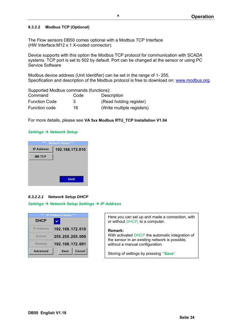
The Flow sensors DB50 comes optional with a Modbus TCP Interface (HW Interface:M12 x 1 X-coded connector). Device supports with this option the Modbus TCP protocol for communication with SCADA systems. TCP port is set to 502 by default. Port can be changed at the sensor or using PC Service Software Modbus device address (Unit Identifier) can be set in the range of 1- 255. Specification and description of the Modbus protocol is free to download on: www.modbus.org. Supported Modbus commands (functions): Command Code Description Function Code 3 (Read holding register) Function code 16 (Write multiple registers) For more details, please see VA 5xx Modbus RTU_TCP Installation V1.04 Settings Network Setup
8.3.2.2.1 Network Setup DHCP
Settings Network Setup Settings IP Address
Here you can set up and made a connection, with or without DHCP, to a computer. Remark: With activated DHCP the automatic integration of the sensor in an existing network is possible, without a manual configuration. Storing of settings by pressing “Save“
^ Operation
DB50 English V1.18 Seite 35
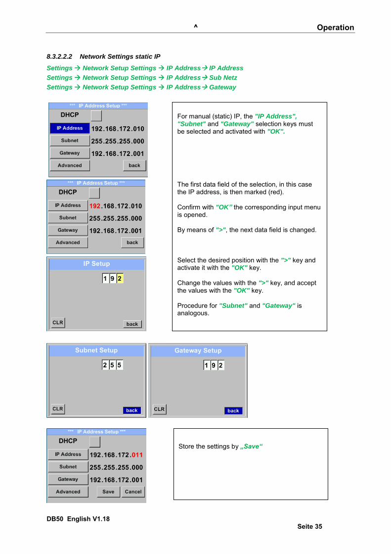
8.3.2.2.2 Network Settings static IP
Settings Network Setup Settings IP Address IP Address
Settings Network Setup Settings IP Address Sub Netz
Settings Network Setup Settings IP Address Gateway
For manual (static) IP, the "IP Address", "Subnet" and "Gateway" selection keys must be selected and activated with "OK". The first data field of the selection, in this case the IP address, is then marked (red). Confirm with "OK” the corresponding input menu is opened. By means of ">", the next data field is changed. Select the desired position with the ">" key and activate it with the "OK" key. Change the values with the ">" key, and accept the values with the "OK" key. Procedure for "Subnet" and "Gateway" is analogous.
Store the settings by „Save“

^ Operation
DB50 English V1.18 Seite 36
8.3.2.2.3 Modbus TCP Settings
Settings Network Setup Settings IP Address MB TCP
Settings Network Setup Settings IP Address ID
Settings Network Setup Settings IP Address Port
For changes, e.g. the sensor ID, first select by pressing key „>“ the field “ID” and then key “OK”. Select the desired position by pressing the ">" and select with "OK" button. Change values by pressing the „>“ values takeover by pressing "OK". Input for the port is done analogue. By means of the button "Byte Format" it is possible to change the data format (Word Order). Possible formats are "ABCD" (Little Endian) and "CDAB" (Middle Endian) Saving the changes by pressing "Save", therefore select it with key „>“ and then confirm it with "OK". Reset to the default settings by activating "Set to
Default"-

^ Operation
DB50 English V1.18 Seite 37
8.3.2.3 Modbus Settings Register (2001…2005)
Modbus Register
Register Address
No.of Byte
Data Type Description Default
Setting Read Write Unit /Comment
2001 2000 2 UInt16 Modbus ID 1 R/W Modbus ID 1…247
2002 2001 2 UInt16 Baudrate 4 R/W
0 = 1200 1 = 2400 2 = 4800 3 = 9600 4 = 19200 5 = 38400
2003 2002 2 UInt16 Parity 1 R/W 0 = none 1 = even 2 = odd
2004 2003 2 UInt16 Number of Stopbits R/W 0 = 1 Stop Bit 1 = 2 Stop Bit
2005 2004 2 UInt16 Word Order 0xABCD R/W 0xABCD = Big Endian 0xCDAB = Middle Endian
8.3.2.4 Values Register (1001 …1500)
Modbus Register
Register Address
No.of Byte Data Type Description Def
ault Read Write Unit /Comment
1101 1100 4 Float Flow in m³/h R
1109 1108 4 Float Flow in Nm³/h R
1117 1116 4 Float Flow in m³/min R
1125 1124 4 Float Flow in Nm³/min R
1133 1132 4 Float Flow in ltr/h R
1141 1140 4 Float Flow in Nltr/h R
1149 1148 4 Float Flow in ltr/min R
1157 1156 4 Float Flow in Nltr/min R
1165 1164 4 Float Flow in ltr/s R
1173 1172 4 Float Flow in Nltr/s R
1181 1180 4 Float Flow in cfm R
1189 1188 4 Float Flow in Ncfm R
1197 1196 4 Float Flow in kg/h R
1205 1204 4 Float Flow in kg/min R
1213 1212 4 Float Flow in kg/s R
1221 1220 4 Float Flow in kW R
^ Operation
DB50 English V1.18 Seite 38
Modbus Register
Register Address
No.of Byte
Data Type Description Default Read
Write Unit /Comment
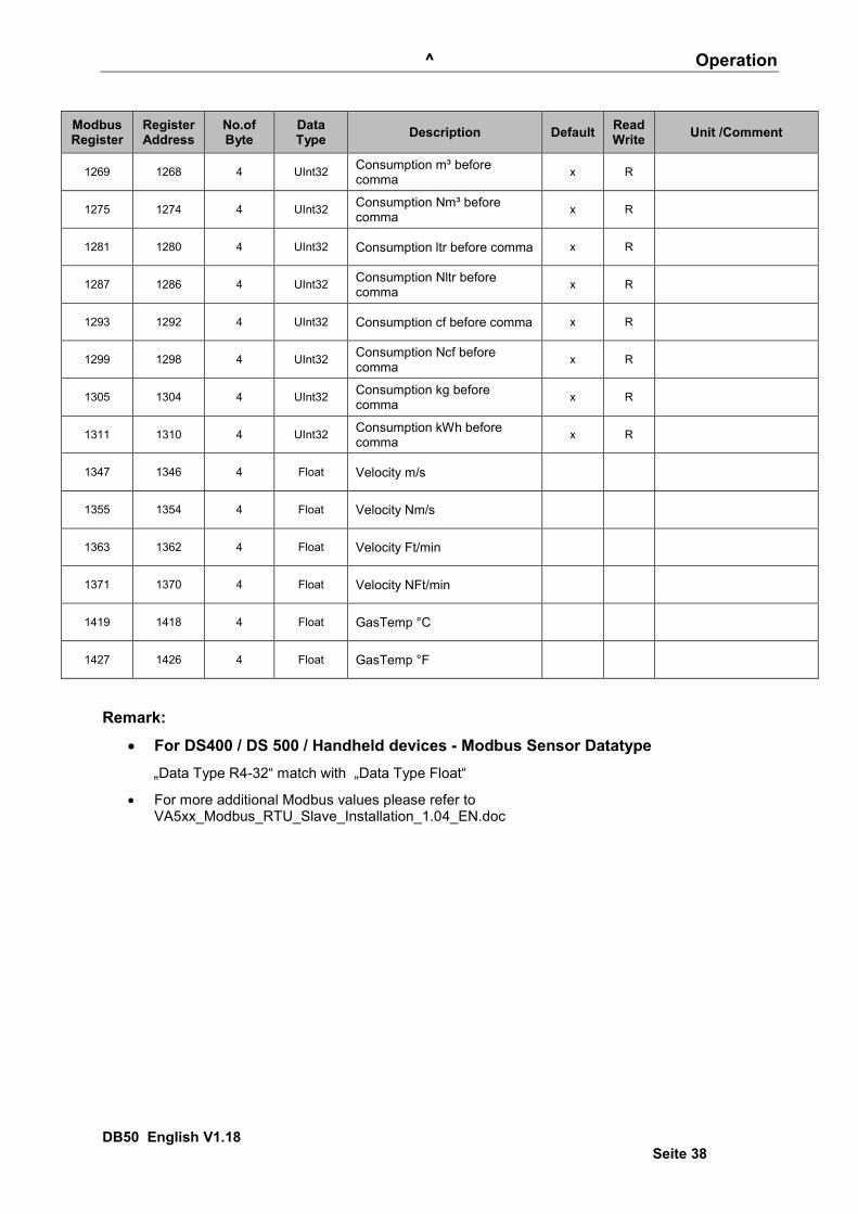
1269 1268 4 UInt32 Consumption m³ before comma x R
1275 1274 4 UInt32 Consumption Nm³ before comma x R
1281 1280 4 UInt32 Consumption ltr before comma x R
1287 1286 4 UInt32 Consumption Nltr before comma x R
1293 1292 4 UInt32 Consumption cf before comma x R
1299 1298 4 UInt32 Consumption Ncf before comma x R
1305 1304 4 UInt32 Consumption kg before comma x R
1311 1310 4 UInt32 Consumption kWh before comma x R
1347 1346 4 Float Velocity m/s
1355 1354 4 Float Velocity Nm/s
1363 1362 4 Float Velocity Ft/min
1371 1370 4 Float Velocity NFt/min
1419 1418 4 Float GasTemp °C
1427 1426 4 Float GasTemp °F
Remark:
For DS400 / DS 500 / Handheld devices - Modbus Sensor Datatype „Data Type R4-32“ match with „Data Type Float“
For more additional Modbus values please refer to VA5xx_Modbus_RTU_Slave_Installation_1.04_EN.doc
^ Operation
DB50 English V1.18 Seite 39
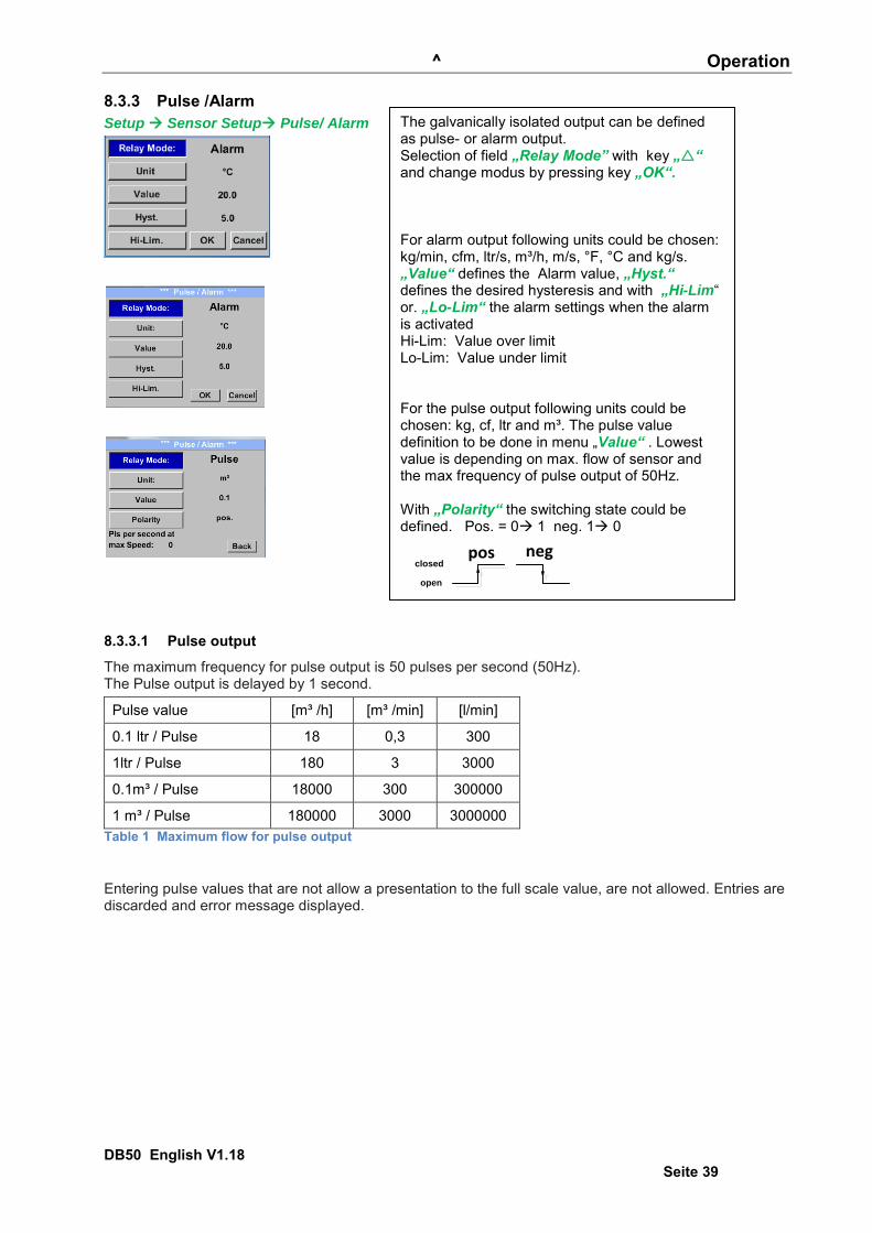
8.3.3 Pulse /Alarm Setup Sensor Setup Pulse/ Alarm
8.3.3.1 Pulse output
The maximum frequency for pulse output is 50 pulses per second (50Hz). The Pulse output is delayed by 1 second.
Pulse value [m³ /h] [m³ /min] [l/min]
0.1 ltr / Pulse 18 0,3 300
1ltr / Pulse 180 3 3000
0.1m³ / Pulse 18000 300 300000
1 m³ / Pulse 180000 3000 3000000 Table 1 Maximum flow for pulse output
Entering pulse values that are not allow a presentation to the full scale value, are not allowed. Entries are discarded and error message displayed.
The galvanically isolated output can be defined as pulse- or alarm output. Selection of field „Relay Mode” with key „“ and change modus by pressing key „OK“. For alarm output following units could be chosen: kg/min, cfm, ltr/s, m³/h, m/s, °F, °C and kg/s. „Value“ defines the Alarm value, „Hyst.“ defines the desired hysteresis and with „Hi-Lim“ or. „Lo-Lim“ the alarm settings when the alarm is activated Hi-Lim: Value over limit Lo-Lim: Value under limit For the pulse output following units could be chosen: kg, cf, ltr and m³. The pulse value definition to be done in menu „Value“ . Lowest value is depending on max. flow of sensor and the max frequency of pulse output of 50Hz. With „Polarity“ the switching state could be defined. Pos. = 0 1 neg. 1 0
pos neg
open
closed
^ Operation
DB50 English V1.18 Seite 40
8.3.4 User Setup
8.3.4.1 Password
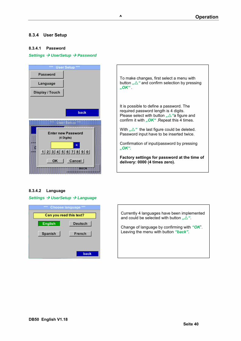
Settings UserSetup Password
8.3.4.2 Language
Settings UserSetup Language
To make changes, first select a menu with button „“ and confirm selection by pressing „OK“ . It is possible to define a password. The required password length is 4 digits. Please select with button „“a figure and confirm it with „OK“ .Repeat this 4 times. With „“ the last figure could be deleted. Password input have to be inserted twice. Confirmation of input/password by pressing „OK“. Factory settings for password at the time of delivery: 0000 (4 times zero).
Currently 4 languages have been implemented and could be selected with button „“. Change of language by confirming with “OK”. Leaving the menu with button “back”.

^ Operation
DB50 English V1.18 Seite 41
8.3.4.3 Display / Touch
Settings UserSetup Display / Touch
8.3.5 Advanced Settings Advanced
By pressing „Factory Reset“ the sensor is set back to the factory settings.
With the button „-“ and with button „+“ it is possible to adjust the backlight / display brightness.The actual / adjusted backlight brightness is showed in the graph „Backlight.“ By activation “Dimming after” and entering a time a display dimming could be set. With „Rotate Screen“ the display information could be rotated by 180°. By activation of „Key Lock“ the operation of the sensor locked. Unlocking the keyboard is only possible by restarting the sensor and calling the operating menu within the first 10s. To do this, use the "OK" button to enter the operating menu during this period
^ Operation
DB50 English V1.18 Seite 42
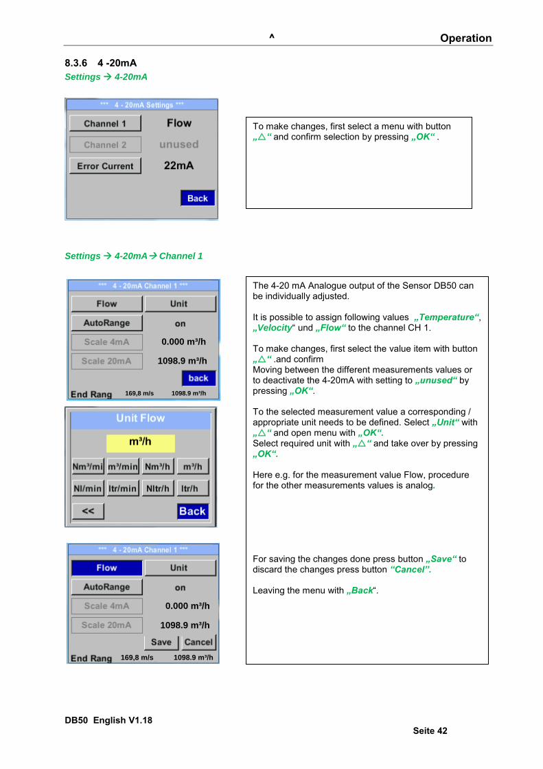
8.3.6 4 -20mA Settings 4-20mA
Settings 4-20mA Channel 1
0.000 m³/h
1098.9 m³/h
169,8 m/s 1098.9 m³/h
1098.9 m³/h
0.000 m³/h
169,8 m/s 1098.9 m³/h
To make changes, first select a menu with button „“ and confirm selection by pressing „OK“ .
The 4-20 mA Analogue output of the Sensor DB50 can be individually adjusted. It is possible to assign following values „Temperature“, „Velocity“ und „Flow“ to the channel CH 1. To make changes, first select the value item with button „“ .and confirm Moving between the different measurements values or to deactivate the 4-20mA with setting to „unused“ by pressing „OK“. To the selected measurement value a corresponding / appropriate unit needs to be defined. Select „Unit“ with „“ and open menu with „OK“. Select required unit with „“ and take over by pressing „OK“. Here e.g. for the measurement value Flow, procedure for the other measurements values is analog. For saving the changes done press button „Save“ to discard the changes press button “Cancel”. Leaving the menu with „Back“.

^ Operation
DB50 English V1.18 Seite 43
End Range 169,8m/s 1098,9 m³/h
1098,9 m³/h
Settings 4-20mA Error Current
The scaling of the 4-20mA channel can be done automatically "Auto Range = on" or manual "AutoRange = off" . With button „“ select the menu item „AutoRange“ select with „OK“ the desired scaling method. (Automatically or manually) In case of AutoRange = off with „Scale 4mA“ und „Scale 20mA“ the scale ranges needs to be defined. Select with button „“ the item „Scale 4mA“ or „Scale 20mA“ and confirm with „OK“ . Input of the scaling values will be analogous as described before for value settings. Using „CLR“ clears up the complete settings at once. For „Auto on“ , the max. scaling is calculated based on the inner tube diameter, max. measurement range and the reference conditions settings. Take over of the inputs with „Save“ and leaveing the menu with „Back“.
This determines what is output in case of an error at the analog output. 2 mA Sensor error / System error 22 mA Sensor error / System error None Output according Namur (3.8mA – 20.5 mA)
< 4mA to 3.8 mA Measuring range under range >20mA to 20.5 mA Measuring range exceeding
To make changes first select a menu item "Current Error" with button „“ and then select by pressing the „OK“ the desired mode For saving the changes done press button „Save“ to discard the changes press button “Cancel”. Leaving the menu with „Back“.
^ Operation
DB50 English V1.18 Seite 44 v
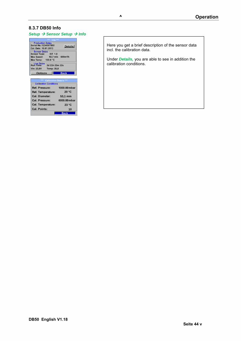
8.3.7 DB50 Info Setup Sensor Setup Info
Run Time: 2d 21h 23m 12s
Vin: 23,8V Temp: 35,8
92,7 m/s 600m³/h
20 °C
53,1 mm
23 °C
10
Here you get a brief description of the sensor data incl. the calibration data. Under Details, you are able to see in addition the calibration conditions.
^ Operation
DB50 English V1.18 Seite 45
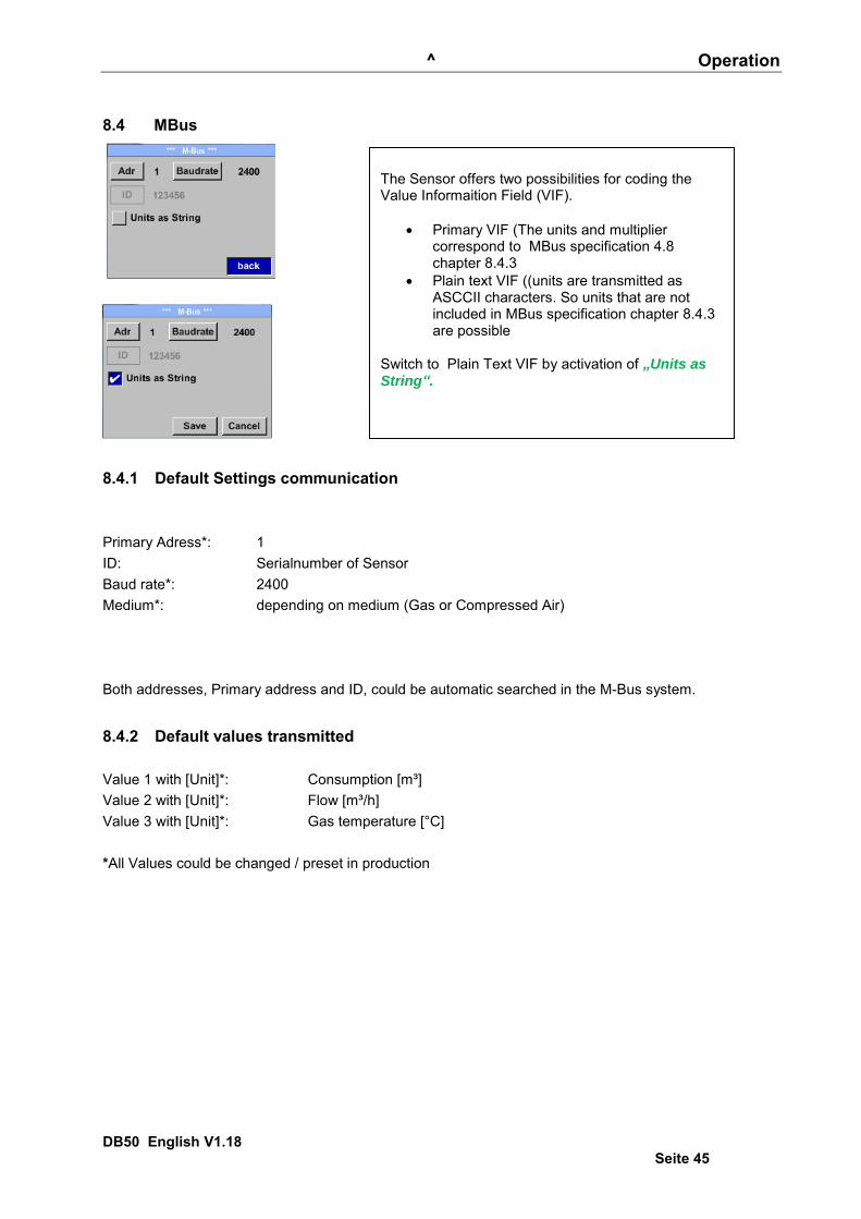
8.4 MBus
8.4.1 Default Settings communication Primary Adress*: 1 ID: Serialnumber of Sensor Baud rate*: 2400 Medium*: depending on medium (Gas or Compressed Air)
Both addresses, Primary address and ID, could be automatic searched in the M-Bus system.
8.4.2 Default values transmitted Value 1 with [Unit]*: Consumption [m³] Value 2 with [Unit]*: Flow [m³/h] Value 3 with [Unit]*: Gas temperature [°C] *All Values could be changed / preset in production
The Sensor offers two possibilities for coding the Value Informaition Field (VIF).
Primary VIF (The units and multiplier correspond to MBus specification 4.8 chapter 8.4.3
Plain text VIF ((units are transmitted as ASCCII characters. So units that are not included in MBus specification chapter 8.4.3 are possible
Switch to Plain Text VIF by activation of „Units as String“.

Status / Error messages
DB50 English V1.18 Seite 46
9 Status / Error messages
9.1 Status messages
CAL A regular re-calibration is recommended, see chapter 13.
At delivery, the date at which the next recalibration is recommended is internally entered. When this date is reached, a message appears in the display with the status message „CAL“. Note: The measurement will continue without interruption or restriction.
Direction When used in conjunction with a direction switch, the status message "Direction" is displayed in case of opposite flow direction and no measurement may take place. Status messages:
Direction
Status / Error messages
DB50 English V1.18 Seite 47
9.2 Error messages
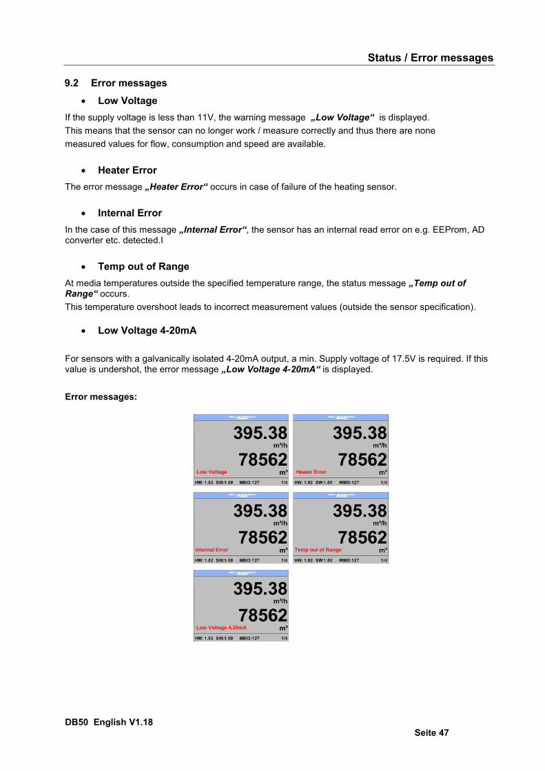
Low Voltage If the supply voltage is less than 11V, the warning message „Low Voltage“ is displayed. This means that the sensor can no longer work / measure correctly and thus there are none measured values for flow, consumption and speed are available.
Heater Error The error message „Heater Error“ occurs in case of failure of the heating sensor.
Internal Error In the case of this message „Internal Error“, the sensor has an internal read error on e.g. EEProm, AD converter etc. detected.I
Temp out of Range At media temperatures outside the specified temperature range, the status message „Temp out of Range“ occurs. This temperature overshoot leads to incorrect measurement values (outside the sensor specification).
Low Voltage 4-20mA For sensors with a galvanically isolated 4-20mA output, a min. Supply voltage of 17.5V is required. If this value is undershot, the error message „Low Voltage 4-20mA“ is displayed. Error messages:
*** VA 520 ***
Low Voltage
*** VA 520 ***
Heater Error
*** VA 520 ***
Internal Error
*** VA 520 ***
Temp out of Range
*** VA 520 ***
Low Voltage 4.20mA

Maitenance / Warranty
DB50 English V1.18 Seite 48
10 Maintenance The sensor head should be checked regularly for dirt and cleaned if necessary. Should dirt, dust or oil accumulate on the sensor element, a deviation will occur in the measuring value. An annual check is recommended. Should the compressed air be heavily soiled this interval must be shortened.
11 Cleaning of the sensor head The sensor head can be cleaned by carefully moving it back and forth in warm water with a small amount of washing-up liquid. Avoid physical intervention on the sensor (e.g. using a sponge or brush). If soiling cannot be removed, the manufacturer must carry out service and maintenance.
12 Re-Calibration If no customer specifications are given then we recommend carrying out calibration every 12 months. For this purpose, the sensor must be sent to the manufacturer.
13 Spare parts and repair For reasons of measuring accuracy spare parts are not available. If parts are faulty, they must be sent to the supplier for repair. If the measuring device is used in important company installations, we recommend keeping a spare measuring system ready.
14 Calibration According to DIN ISO certification of the measuring instruments we recommend to calibrate and if applicable to adjust the instruments regularly from the manufacturer. The calibration intervals should comply with your internal specification. According to DIN ISO we recommend a calibration interval of one year for the instrument DB50. On request and additional payment, calibration-certificates could be issued. The precision is given due to use DKD-certified flow meters and verifiable
15 Warranty If you have reason for complaint, we will of course repair any faults free of charge if it can be proven that they are manufacturing faults. The fault should be reported immediately after it has been found and within the warranty time guaranteed by us. Excluded from this warranty is damage caused by improper use and non-adherence to the instruction manual. The warranty is also cancelled once the instrument has been opened - as far as this has not been mentioned in the instruction manual for maintenance purposes - or if the serial number in the instrument has been changed, damaged or removed. The warranty time for the DB50 is 12 months. If no other definitions are given the accessory parts have a warranty time of 6 months. Warranty services do not extend the warranty time. If in addition to the warranty service necessary repairs, adjustments or similar are carried out the warranty services are free of charge but there is a charge for other services such as transport and packaging costs. Other claims, especially those for damage occurring outside the instrument, are not included unless responsibility is legally binding. After sales service after the warranty time has elapsed We are of course there for you even after the warranty time has elapsed. In case of malfunctions, please send us the instrument with a short-form description of the fault. Please do not forget to indicate your telephone number so that we can call you in case of any questions.

Flow Measurement and Monitoring
DB50Thermal Mass Flowmeter and Counter for Compressed Airand Non-Aggressive Gases
• insertion model
• available for DN 25 (1”) to DN 600 (24”) pipe sizes
• for flow velocities:0...92,7 m/s, 0...185 m/sor 0...224 m/s
• local LCD-display for flow rateand total optional
• output signals: 4...20 mA forflow rate and total
• for compressed air and non-aggressive gases
• zero balance possible at instrument
Description:
Model DB50 thermal mass flow meters and counters reportand measure mass flow rates and totals of non-aggressivegases, regardless of gas pressure and temperature. Process gas flows around a heated temperature sensor that isencapsulated in glass. As a result, the sensor dissipates heatwhich an electronics module returns to the sensor to maintainit at a constant temperature. The dissipated heat energy isproportional to the mass flow rate of the gas and is output asa 4 to 20 mA signal by the electronic utilizing calibrationcurves and process parameters stored in the instrument. The 4 to 20 mA signal is routed to secondary evaluation devi-ces and provides the flow rate information. An additional pulseoutput with a pre-defined pulse value is used for totalizingpurposes. Mass flow rate and total may also be displayed onan integrated back-lit display if required. The instruments aresupplied with a 1/2” thread compression fitting and can beinstalled and disassembled under pressurized conditions.
Typical applications:
Model DB50 thermal mass flow meters and counters provideflow measurement of non-aggressive gases in DN 25 toDN 600 pipe systems. Their rugged, heavy-duty design andeasy handling and operation make them the right choice formeasuring and monitoring compressed air consumptionlevels. They also provide measurements of other suitablegases such as: nitrogen oxygen, argon, helium and carbondioxide.
PKP Prozessmesstechnik GmbHBorsigstr. 24 • D-65205 Wiesbaden
S +49 (0) 6122-7055-0 • +49 (0) 6122 7055-50 [email protected] • www.pkp.de
PKP Process Instruments Inc.10 Brent Drive • Hudson, MA 01749
S +1-978-212-0006 • +1-978-568-0060 [email protected] • www.pkp-usa.com
160509

Models:DB50.S… standard-model, mass flow rate
0…92,7 m/s, G 1/2 male threadDB50.H1… mass flow rate 0…185 m/s,
G 1/2 male thread DB50.H2… mass flow rate 0…224 m/s,
G 1/2 male thread
Measuring ranges:The quoted measuring ranges are a rough guide only. The exactmeasuring ranges are calculated taking the actual insidediameter of the given pipe into account and are used duringproduction to calibrate the instruments.
Air: Nom-inalpipesize
Pipeinner
diameter[mm]
Measuring range end values (20mA)
[Nm³/h] -Air*
Probelength[mm]
DB50.S0…92,7
m/s
DB50.H10…185 m/s
DB50.H20...224 m/s
DN 25 27,3 148 295 357120
DN 32 36,0 266 531 644DN 40 41,9 366 728 882
160DN 50 53,1 600 1198 1450DN 65 71,1 1095 2187 2648DN 80 84,9 1569 3133 3794
DN 100 110,0 2644 5279 6391
220DN 125 133,7 3921 7808 9453DN 150 159,3 5579 11.097 13.436DN 200 200,0 8816 17.533 21.230DN 250 250,0 13.742 27.429 33.211
300DN 300 300,0 19.836 39.545 47.881DN 500 500,0 55.101 109.846 133.002
400DN 600 600,0 79345 158.178 191.524
* based on 20 °C and 1000 mbar
Gases:DB50.S: 0…92,7 m/s (standard)
Nom-inalpipe
size**
Measuring range end values* (20 mA)[Nm³/h]
Ar CO2 N2 O2 N2O Naturalgas
DN 25 231 146 131 141 145 87DN 32 416 263 237 254 261 157DN 40 571 361 324 348 358 216DN 50 938 594 533 572 588 355DN 65 1713 1084 974 1045 1075 648DN 80 2454 1553 1396 1497 1540 928DN 100 4134 2617 2351 2522 2594 1564DN 125 6115 3870 3478 3731 3836 2313DN 150 8692 5501 4943 5303 5453 3287DN 200 13.733 8691 7810 8378 8615 5194DN 250 21.483 13.596 12.217 13.107 13.477 8125DN 300 30.973 19.601 17.613 18.896 19.430 11.713DN 500 86.036 54.448 48.926 52.489 53.973 32.538DN 600 123.892 78.405 70.453 75.583 77.721 46.855
* based on 1013 mbar and 0 °C, ** pipe inner diameter as in the table „Air“, further gases on request
DB50.H1 = 0…185 m/sNom-inalpipe
size**
Measuring range end values* (20 mA)[Nm³/h]
Ar CO2 N2 O2 N2O Naturalgas
DN 25 461 292 262 281 289 174DN 32 831 526 473 507 521 314DN 40 1139 721 648 695 714 431DN 50 1872 1185 1065 1142 1174 708DN 65 3419 2164 1945 2085 2144 1293DN 80 4898 3101 2986 2988 3072 1853
DN 100 8252 5224 4694 5033 5176 3122DN 125 12.205 7727 6942 7445 7656 4617DN 150 17.347 10.983 9867 10.581 10.881 6562DN 200 27.409 17.353 15.591 16.718 17.192 10.368DN 250 42.878 27.147 24.389 26.154 26.895 16.220DN 300 61.818 39.138 35.163 37.706 38.775 23.385DN 500 171.716 108.718 97.674 104.739 107.708 64.958DN 600 247.271 156.553 140.650 150.825 155.100 93.539
* based on 1013 mbar and 0 °C** pipe inner diameter as in the table „Air“
further gases on request
DB50.H2 = 0…224 m/sNom-inalpipe
size**
Measuring range end values* (20 mA)[Nm³/h]
Ar CO2 N2 O2 N2O Erdgas
DN 25 558 353 317 340 350 211DN 32 1006 637 572 614 631 381DN 40 1379 873 784 841 865 522DN 50 2267 1435 1290 1383 1422 858DN 65 4140 2619 2355 2525 2597 1566DN 80 5931 3753 3374 3618 3721 2244DN 100 9992 6323 5684 6095 6269 3781DN 125 14.779 9352 8407 9015 9272 5592DN 150 21.006 13.292 11.949 12.812 13.178 7948DN 200 33.190 21.002 18.879 20.244 20.822 12.558DN 250 51.922 32.855 29.534 31.669 32.574 19.645DN 300 74.857 47.368 42.580 45.658 46.962 28.322DN 500 207.935 131.577 118.277 126.827 130.449 78.673DN 600 299.427 189.472 170.319 182.631 187.847 113.290
* based on1013 mbar and 0 °C** pipe inner diameter as in the table „Air“
further gases on request
PKP Prozessmesstechnik GmbHBorsigstr. 24 • D-65205 Wiesbaden
S +49 (0) 6122-7055-0 • +49 (0) 6122 7055-50 [email protected] • www.pkp.de
PKP Process Instruments Inc.10 Brent Drive • Hudson, MA 01749
S +1-978-212-0006 • +1-978-568-0060 [email protected] • www.pkp-usa.com

Display: (optional)
Display: TFT 1,8“ Resolution: 220 x 176Indication: 2 values simultaneous:
actual flow and totoal flow (counter rate)
Menu navigation: multilingualAdjustable via key at the display:
inner diameter of pipecounter resetunit selection4...20 mA scalingreference conditions (°C, mbar)pulse valuezero point balanceleak flow volume depression
Indication: rotatable at 180°
Electrical connection:
Pin 1 Pin 2 Pin 3 Pin 4 Pin 5
Connection plug A
+VB RS 485 (A)
-VB RS 485 (B)
I+ (4...20 mA)
Connection plug B(pulse output)
NC GND DIR pulse(galv. isolated)
pulse(galv. isolated)
Connection plug B(option MBus)
NC NC NC MBus MBus
Farben brown white blue black grey
Connection plug 5-pole:
Connection plug A:
Connection plug B (pulse output / MBus):
Technical Data:
Parameters: Nm³/h, Nl/minReference conditions : 20 °C, 1000 mbar (standard at
air)0 °C, 1013 mbar (standard at gases) other adjustable via key or factory-made
Adjustable units: m³/h (Standard) m³/min, l/min, l/s, ft/min, cfm, m/s, kg/h, kg/min, kg/s
Measuring medium: air, nitrogen, argon, nitrous oxide, CO2, oxigen, natural gas
Sensor: Pt45, Pt1000 T90: < 2 secondsOperating temperature: -30...110 °C (probe tube
-30 ... 80 °C (housing)Operating pressure: up to 50 bar Power supply: 18 bis 36 VDC Power consumption: max. 5 W Burden: < 500 OhmDigital output: RS 485 (Modbus RTU ) Analogue output: 4...20 mA for m³/h bzw. l/min
other scaling on requestPulse output: 1 pulse per m³ resp. per litre,
galvanically separated scaling adjustable via keys
Accuracy: ± 1,5 % of m.v., ± 0,3 % of f.s. ± 1 % of m.v., ± 0,3 % of f.s (optional)
Display (optional): TFT 1,8“Process connection: G ½“ Mounting position: anyMaterial: housing: Polycarbonate
st. st. 1.4301, Electrical protection: IP 65
Dimensions:
PKP Prozessmesstechnik GmbHBorsigstr. 24 • D-65205 Wiesbaden
S +49 (0) 6122-7055-0 • +49 (0) 6122 7055-50 [email protected] • www.pkp.de
PKP Process Instruments Inc.10 Brent Drive • Hudson, MA 01749
S +1-978-212-0006 • +1-978-568-0060 [email protected] • www.pkp-usa.com
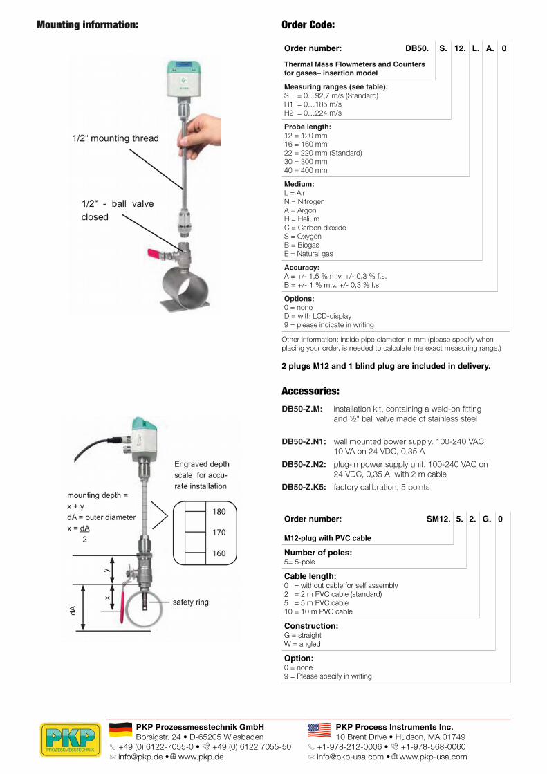
Mounting information: Order Code:
Order number: DB50.
Thermal Mass Flowmeters and Countersfor gases– insertion model
S. 12. L. A. 0
Measuring ranges (see table):S = 0…92,7 m/s (Standard)H1 = 0…185 m/sH2 = 0…224 m/sProbe length:12 = 120 mm16 = 160 mm22 = 220 mm (Standard)30 = 300 mm40 = 400 mmMedium:L = AirN = NitrogenA = ArgonH = HeliumC = Carbon dioxideS = OxygenB = BiogasE = Natural gasAccuracy:A = +/- 1,5 % m.v. +/- 0,3 % f.s.B = +/- 1 % m.v. +/- 0,3 % f.s.Options:0 = noneD = with LCD-display9 = please indicate in writing
Other information: inside pipe diameter in mm (please specify whenplacing your order, is needed to calculate the exact measuring range.)
2 plugs M12 and 1 blind plug are included in delivery.
Accessories:DB50-Z.M: installation kit, containing a weld-on fitting
and ½" ball valve made of stainless steel
DB50-Z.N1: wall mounted power supply, 100-240 VAC, 10 VA on 24 VDC, 0,35 A
DB50-Z.N2: plug-in power supply unit, 100-240 VAC on 24 VDC, 0,35 A, with 2 m cable
DB50-Z.K5: factory calibration, 5 points
Order number: SM12.
M12-plug with PVC cable
5. 2. G. 0
Number of poles:5= 5-pole
Cable length:0 = without cable for self assembly2 = 2 m PVC cable (standard)5 = 5 m PVC cable10 = 10 m PVC cable
Construction:G = straightW = angled
Option:0 = none9 = Please specify in writing
PKP Prozessmesstechnik GmbHBorsigstr. 24 • D-65205 Wiesbaden
S +49 (0) 6122-7055-0 • +49 (0) 6122 7055-50 [email protected] • www.pkp.de
PKP Process Instruments Inc.10 Brent Drive • Hudson, MA 01749
S +1-978-212-0006 • +1-978-568-0060 [email protected] • www.pkp-usa.com