instruction manual en 1298 – im – gb - scaffold tower · pdf fileif it is...
TRANSCRIPT
©
This document will provide all users of Lewis Access Towers a
complete guide to the erection of both the Lewis DW (Double
Width) and Lewis SW (Single Width) Aluminium Towers,
employing the 3T (Through the Trap) method.
The user should read the entire contents of this document
before commencing assembly and pay particular attention
to all of the safety instructions.
If the equipment is passed onto another party a copy of
these instructions should accompany the handover.
Two persons are necessary to carry out the erection of the equipment
detailed in this document
It is strongly recommended that the following items of personal protection
equipment be worn at all times: safety boots (EN345 or BS1870 / 4972);
safety helmet (EN397 or BS5240); gloves.
The SWL(Safe Working Load) for each platform is 275kg, evenly dispersed.
Additional items, such as steps or conventional ladders, must never be used
to gain further height from the platform.
The tower must be climbed from within the structure, on no occasions should
the tower be scaled from the outside.
Inspect all the tower components before each use. Pay particular attention to;
Castings - check for cracks
Welds - free from cracks
Tubes/Braces/Rungs - Straight and with indents less than 5mm
deep
Platforms - no damage, free from debris
Castors - moves freely, threads free from damage, brake working
Outriggers - straight, feet flat
Inspect the equipment for damage regularly, at least daily.
Ladder Frame
Toeboard
Platform
Trap and
Fixed
Horizontal
Brace
Diagonal
Brace
Ladder
Frame
2-Rung
Frame
Adjustable
Leg
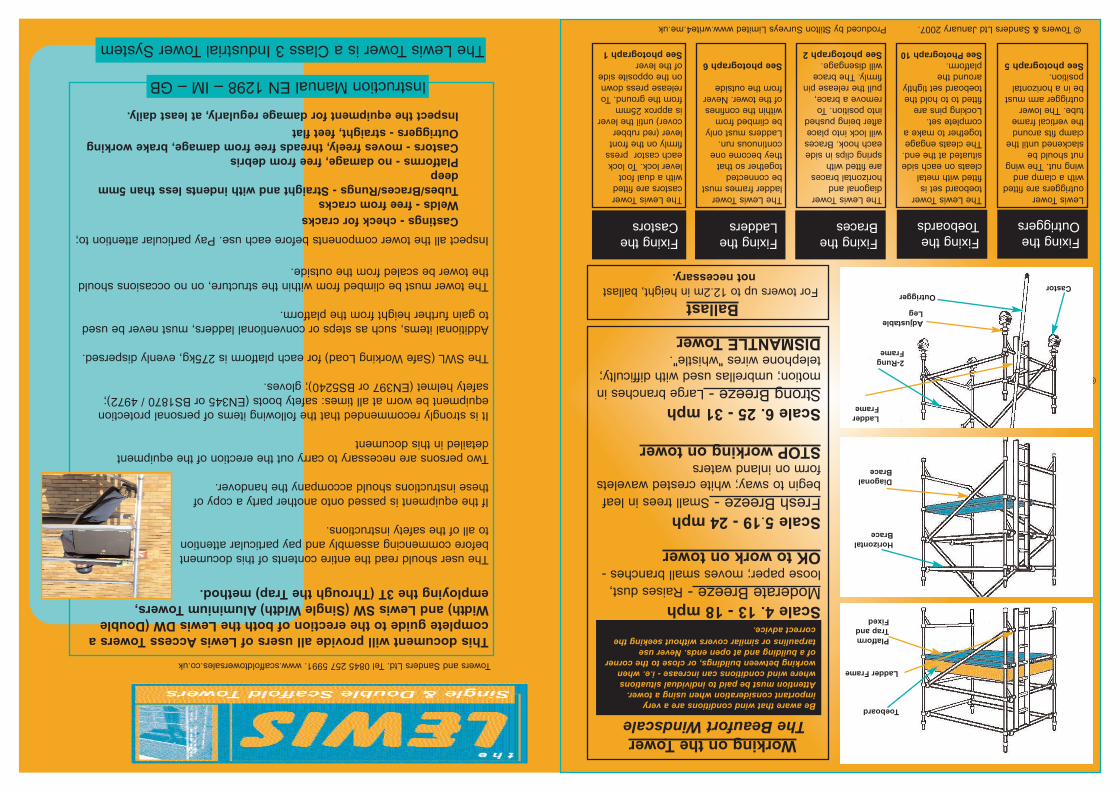
OutriggerCastor
Fixing the
Outriggers
Fixing the
Toeboards
Fixing the
Braces
Fixing the
Ladders
Fixing the
Castors
© Towers &Sanders Ltd January 2007.Produced by Stilton Surveys Limited www.write4.me.uk
Working on the Tower
The Beaufort Windscale
Scale 4. 13 - 18 mph
Moderate Breeze - Raises dust,
loose paper; moves small branches -
OK to work on tower
Scale 5.19 - 24 mph
Fresh Breeze - Small trees in leaf
begin to sway; white crested wavelets
form on inland waters
STOPworking on tower
Scale 6. 25 - 31 mph
Strong Breeze - Large branches in
motion; umbrellas used with difficulty;
telephone wires "whistle".
DISMANTLE Tower
Be aware that wind conditions are a veryimportant consideration when using a tower.Attention must be paid to individual situationswhere wind conditions can increase - i.e. whenworking between buildings, or close to the cornerof a building and at open ends. Never usetarpaulins or similar covers without seeking thecorrect advice.without seeking proper advice.
The Lewis Tower is a Class 3 Industrial Tower System
BallastFor towers up to 12.2m in height, ballast
not necessary.
The Lewis Tower
toeboard set is
fitted with metal
cleats on each side
situated at the end.
The cleats engage
together to make a
complete set.
Locking pins are
fitted to to hold the
toeboard set tightly
around the
platform.See Photograph 10
The Lewis Tower
diagonal and
horizontal braces
are fitted with
spring clips in side
each hook. Braces
will lock into place
after being pushed
into position. To
remove a brace,
pull the release pin
firmly. The brace
will disengage.
See photograph 2
The Lewis Tower
ladder frames must
be connected
together so that
they become one
continuous run.
Ladders must only
be climbed from
within the confines
of the tower. Never
from the outside
See photograph 6
The Lewis Tower
castors are fitted
with a dual foot
lever lock. To lock
each castor press
firmly on the front
lever (red rubber
cover) until the lever
is approx 25mm
from the ground. To
release press down
on the opposite side
of the lever
See photograph 1
Lewis Tower
outriggers are fitted
with a clamp and
wing nut. The wing
nut should be
slackened until the
clamp fits around
the vertical frame
tube. The lower
outrigger arm must
be in a horizontal
position.
See photograph 5
Instruction Manual EN 1298 – IM – GB
Towers and Sanders Ltd. Tel 0845 257 5991. www.scaffoldtowersales.co.uk
Check all components(see component list) are available and in usable condition. Damaged or incorrect
components should not be used. If damage should occur whilst in use, stop work immediately and isolate the
damaged items from the rest of the tower and contact your supplier.
Check the ground on which the tower is to be used is relatively flat, smooth and capable of supporting the tower.
The SWL(Safe Working Load) of the tower is 275kg per platform, inc the weight of the tower - evenly distributed, up
to a maximum of 950kgs per tower. Do not exceed the SWL.
Never attach safety harnessesor similar safety equipment to the tower whilst erecting or dismantling the tower.
During assembly, the tower should only be climbed from inside of the frame dimensions,do not scale the tower
from the outside. Tools and equipment must be loaded onto the platform within the confines of the tower dimensions.
Adjustable legs are to be used for levelling. Outriggersshould always be deployed when required.
If the area of operation means that the outriggers cannot be deployed in the recommended position – contact Lewis
Towers or your supplier for advice.
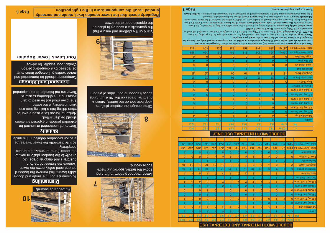
Attach trapdoor platform to 6th rung
above the ladder, approx 3.2 metre
above ground.
Fit toeboards securely
Climb through the trapdoor platform,
keep both feet on the ladder,. Attach 4
guard rail braces on the 7th & 8th rungs
above trapdoor to both sides of platform
Stand on the platform and ensure that
the guardrails are securely in place at
the opposite ends of the tower
7
8
9
10
DismantlingTo dismantle both the single and double
width towers, first remove the toeboard
set and send safely down the tower.
Remove the furthest of the four
guardrails and diagonal brace. Go
directly to the trapdoor platform next to
the ladder frame to remove the braces
completely.
To fully dismantle the tower reverse the
erection procedure detailed in this guide
StabilityTowers left unattended or unused for
extended periods in exposed situations
should be dismantled.
Horizontal forces i.e. pressure exerted
when drilling into a building face can
yield unstability in the tower.
The tower must not be used to gain
access to a neighbouring structure.
Tower are not intended to be suspended
Page 1Page 6
WH3.2m3.74.24.75.25.76.26.77.27.78.28.79.29.710.2
PH1.2m1.72.22.73.23.74.24.75.25.76.26.77.27.78.2
Castor444444444444444
Adjustable Leg444444444444444
2 Rung Lad Frame001001100110011
2 Rung End Frame021001100110011
3 Rung Lad Frame010101010101010
3 Rung End Frame010101010101010
4 Rung Lad Frame101121223233434
4 Rung End Frame101121223233434
Standard Platform111111111111111
Trap Platform111122233334444
Horizontal Brace66661010101414141418181818
Diagonal Brace223456789101112131415
Toeboard Set111111111111111
Fixed Stabiliser000444444440000
Adj Stabiliser000000000004444
Total Tower Wght 1.892kg97105128159161174181189201207237250260264
Total Tower Wght 2.5105k110119142179190195203211224230266279290295
DOUBLEWIDTHINTERNALAND EXTERNALUSE
DOUBLEWIDTHINTERNALUSE ONLY
WH10.7m11.211.712.212.713.213.714.2
PH8.7m9.29.710.210.711.211.712.2
Castor44444444
Adjustable Leg44444444
2 Rung Lad Frame00110011
2 Rung End Frame00110011
3 Rung Lad Frame10101010
3 Rung End Frame10101010
4 Rung Lad Frame45455656
4 Rung End Frame45455656
Standard Platform11111111
Trap Platform55556666
Horizontal Brace2222222226262626
Diagonal Brace1617181920212223
Toeboard Set11111111
Fixed Stabiliser00000000
Adj Stabiliser44444444
Large Stabiliser00000000
Total Tower Wght 1.8290kg298308313344351359366
Total Tower Wght 2.5237kg335346351388396404412
Your Lewis Tower Supplier
Regularly check that the tower remains level, stable and correctly
erected i.e. all the components are in the right position
Transport and StorageComponents should be transported and
stored vertically. Damaged items must
be repaired by a competent person.
Contact your supplier for advice.
If it is necessary to lift individual components whilst assembling the tower, a dependable knot should
fasten each item.
The tower shouldbe manoeuvred into position by hand by pushing it from the base frame. Never
attempt to use any mechanical equipment (i.e. a forklift etc.) to move the tower.
Be aware of overhead obstructions– pay particular attention to any live electrical cables.
Ensure that no persons, materials or tools are on the tower when it is being moved.
Additional care should be taken when moving the tower on uneven or inclining ground. The use of the
castor locks should be deployed when the tower is in position.
When moving the tower the outriggers should only be lifted 35mm from ground level.
Towers under 4m in height are the only towers that should be moved.
Ensure all spring clips
are located in the
locked position
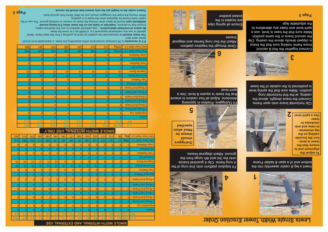
Insert a leg & castor assembly into the
bottom end of a span & ladder Frame
Clip horizontal brace onto span frame.
Connect the brace straight, above the
casting, at the first horizontal rung
position. Make sure that the spring lever
is positioned to the outside of the tower
Fit Outriggers. Position in opposing
directions. Adjust all four castors to ensure
that the tower is square & level. Use a
spirit level
Fit trapdoor platform onto 2nd rung of the
4 rung frame. Clip 4 guardrail braces
onto the 3rd and 4th rungs from the
ground. Attach diagonal braces.
Climb through the trapdoor platform.
Attach the four rung frames and diagonal
braces
Lewis Single Width Tower Erection Order
1
2
3
4
5
6
Page 2Page 5
Connect together the first & second
brace frame making sure that the brace
is clipped directly above the casting. Clip
the second brace in the same position.
Make sure that the base is level, use a
spirit level and make any alterations to
the adjustable legs
WH3.2m3.74.24.75.25.76.26.77.27.78.28.79.29.710.2
PH1.2m1.72.22.73.23.74.24.75.25.76.26.77.27.78.2
Castor444444444444444
Adjustable Leg444444444444444
2 Rung Lad Frame001001100110011
2 Rung End Frame021001100110010
3 Rung Lad Frame010101010101010
3 Rung End Frame010101010101010
4 Rung Lad Frame101121223233434
4 Rung End Frame101121223233434
Standard Platform000000000000000
Trap Platform111122233334444
Horizontal Brace66661010101414141418181818
Diagonal Brace223456789101112131415
Toeboard Set111111111111111
Fixed Stabiliser004444400000000
Adj Stabiliser000000044444444
Large Stabiliser000000000000444
Total Tower Wght 1.874kg77101107138146151160167176180215252286315
Total Tower Wght 2.583g86110117153163168177184194198240278313342
SINGLEWIDTHINTERNALAND EXTERNALUSE
WH10.7m11.211.712.212.713.213.714.2
PH8.7m9.29.710.210.711.211.712.2
Castor44444444
Adjustable Leg44444444
2 Rung Lad Frame00110011
2 Rung End Frame00110011
3 Rung Lad Frame10101010
3 Rung End Frame10101010
4 Rung Lad Frame45455656
4 Rung End Frame45455656
Standard Platform00000000
Trap Platform55556666
Horizontal Brace2222222226262626
Diagonal Brace1617181920212223
Toeboard Set11111111
Fixed Stabiliser00000000
Adj Stabiliser00000000
Large Stabiliser44444444
Total Tower Wght 1.8271kg277286290326332339346
Total Tower Wght 2.5304kg312321326366374381388
SINGLE WIDTHINTERNALUSE ONLY
Outriggers
should
always be
fitted when
specified
To adjust the
alignment and to
ensure that the
tower is level -
turn the knuckle
casting on the
leg clockwise -
to raise and anti-
clockwise to
lower.
Use a spirit level
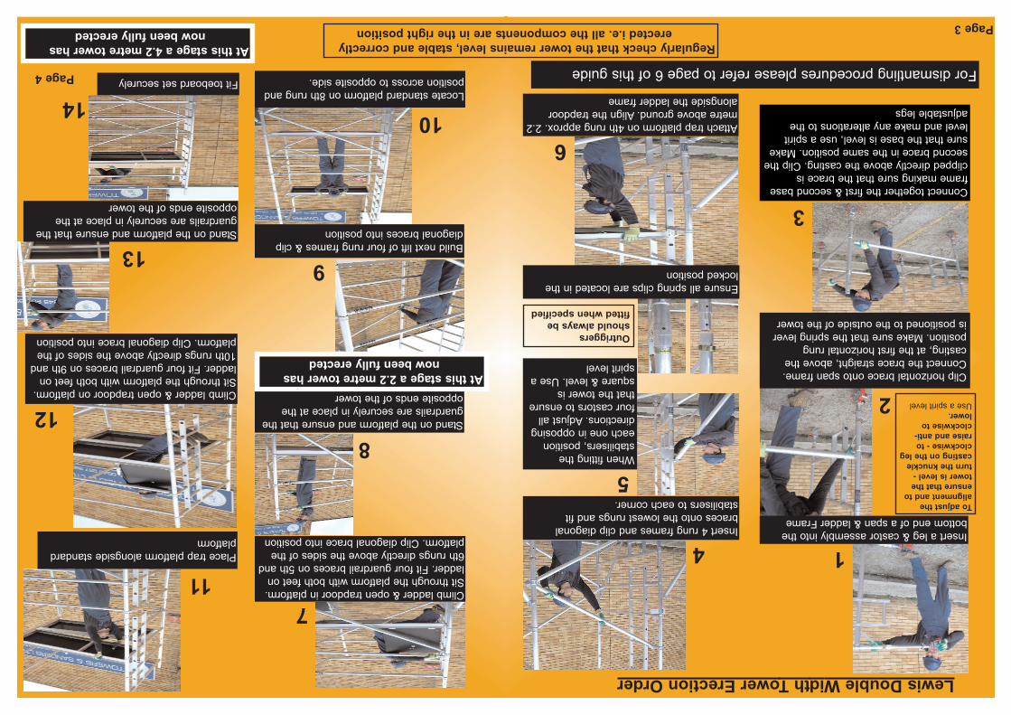
Insert a leg & castor assembly into the
bottom end of a span & ladder FrameInsert 4 rung frames and clip diagonal
braces onto the lowest rungs and fit
stabilisers to each corner.
Attach trap platform on 4th rung approx. 2.2
metre above ground. Align the trapdoor
alongside the ladder frame
Climb ladder & open trapdoor in platform.
Sit through the platform with both feet on
ladder. Fit four guardrail braces on 5th and
6th rungs directly above the sides of the
platform. Clip diagonal brace into position
Locate standard platform on 8th rung and
position across to opposite side.
Stand on the platform and ensure that the
guardrails are securely in place at the
opposite ends of the tower
Place trap platform alongside standard
platform
Stand on the platform and ensure that the
guardrails are securely in place at the
opposite ends of the tower
Fit toeboard set securely
Climb ladder & open trapdoor on platform.
Sit through the platform with both feet on
ladder. Fit four guardrail braces on 9th and
10th rungs directly above the sides of the
platform. Clip diagonal brace into position
Build next lift of four rung frames & clip
diagonal braces into position
Clip horizontal brace onto span frame.
Connect the brace straight, above the
casting, at the first horizontal rung
position. Make sure that the spring lever
is positioned to the outside of the tower
Connect together the first & second base
frame making sure that the brace is
clipped directly above the casting. Clip the
second brace in the same position. Make
sure that the base is level, use a spirit
level and make any alterations to the
adjustable legs
When fitting the
stabilisers, position
each one in opposing
directions. Adjust all
four castors to ensure
that the tower is
square & level. Use a
spirit level
Lewis Double Width Tower Erection Order
7
5
8
9
10
11
13
12
14
6
2
1
3
4
Ensure all spring clips are located in the
locked position
Page 3
Page 4 For dismantling procedures please refer to page 6 of this guideet
At this stage a 2.2 metre tower has
now been fully erected
At this stage a 4.2 metre tower has
now been fully erected
To adjust the
alignment and to
ensure that the
tower is level -
turn the knuckle
casting on the leg
clockwise - to
raise and anti-
clockwise to
lower.
Use a spirit level
Outriggers
should always be
fitted when specified
Regularly check that the tower remains level, stable and correctly
erected i.e. all the components are in the right position