instruction manual for direct-drive oil sealed rotary ... · instruction manual for direct-drive...
TRANSCRIPT

No.62500-2-01-3
Instruction Manual
for
Direct-Drive Oil Sealed Rotary Vacuum Pump
Model GLD-137CCGLD-202BB
Before using the product, be sure to read this manual. Keep this manual in a place where it can be referred to at any time and look after it carefully. The contents of this instruction manual are subject to change without prior notice due to improvements in performance and the functions of the product.
ULVAC KIKO,Inc.

(1/2)
Power Cable Selection Standards Thank you very much for your purchasing our vacuum pump.
This vacuum pump does not have any power cable attached as supplied.
It is up to the user to provide an appropriate power cable for your vacuum pump.
Please be advised of the standards and precautions that you should use to provide
the power cable.
1. Power Cable Selection Standards
The pump is equipped with a single-phase 100-120 V (50/60 Hz) and 200-240 V (50/60 Hz) motor.
Power cable selection standards vary with the working power supply voltage, 100-120V or 200-240V.
The power cable selection standards are shown in a table below.
Do not fail to select your power cable in accordance with the standards.
For a shape of the cable plug to be inserted in the pump motor power inlet, select Type IEC60320-C13.
Power Cable Selection Standards
Supply Voltage Voltage Rating Current Rating Temperature
Rating
100-120V 120V or more 13A or more instantaneous (5sec)
50A or more
200-240V 240V or more 7A or more instantaneous (5sec)
30A or more
70℃ or more
2. Precautions
2.1 Unplug-preventive hardware
Whenever you may operate the vacuum pump with your power cable, provide it with the
unplug-preventive hardware, which should be selected so as to fit the shape of the power cable.
The unplug-preventive hardware allows you to secure the power cable so that the motor may not
Accidentally have it unplugged.
For a procedure for installing the unplug-preventive hardware, refer to “2.2 How to Install
Unplug-preventive Hardware.”
Whenever you may operate the vacuum pump with the power cable, do not fail to secure
it with the unplug-preventive hardware.
Should you operate the vacuum pump without the unplug-preventive hardware, there
is a fear that the power cable may be unplugged during the operation. If so, the
vacuum pump will stop operating, bringing about possibilities, such as electric
shock, injury, fire or the like.
Warning

(2/2)
2.2 How to Install Unplug-preventive Hardware
Install the unplug-preventive hardware in accordance with the procedure as follows:
(1) Let one end of the unplug-preventive hardware
catch the hole to the side of the inlet in the interior.
(2) While pushing the unplug-preventive hardware at
the other end, let it catch the hole to the side of the
inlet in the interior.
(3) Raise the unplug-preventive hardware.
(4) Insert the power cable firmly enough.
(5) Lower the unplug-preventive hardware and
secure the power cable.
Now, the unplug-preventive hardware is completely installed.
(1)(2)
(3)
(4)(5)

EC Declaration of Conformity
We, ULVAC KIKO,Inc.
of 291-7 Chausubaru, Saito-city, Miyazaki, 881-0037. Japan
In accordance with the following Directive:
2006/42/EC Machinery Directive declare under our sole responsibility that the product,
Type of Product : Oil Sealed Rotary Vacuum Pump Model Name : GLD-040,GLD-136A,GLD-137AA, GLD-201A,GLD-202AA,GLD-280A,
GLD-136C,GLD-137CC,GLD-201B, GLD-202BB, GLD-280B
to which this declaration related is in conformity with the following standards:
EN 1012-2:1996+A1:2009 Compressors and vacuum pumps – Safety requirements, Part2. Vacuum pumps IEC/EN 61010-1:2010 Safety requirement for electrical equipment for measurement, control and
laboratory use - Part 1: General requirement IEC/EN 60034-1:2010 Rotating electrical machines
following the provisions of The person stated below will keep the following technical documentation: • operating and maintenance instructions • technical drawings • description of measures designed to ensure conformity • other technical documentation, e.g. quality assurance measures for design and production Person authorized to compile the technical file: ( Name and address) Takaaki Yamaguchi ULVAC Gmbh Parkring11,85748,Garching,Germany
06.Nov, 2013
Miyazaki , Japan Hirofumi Yanagita/ (date & place) (name & signature)

- 01 -
0. Introduction
0.1 Before using the vacuum pump
Thank you for purchasing our vacuum pump (hereinafter called “pump”). When you have received the pump, check that the delivered pump is as per your order and that it has not been damaged in transportation, etc.
In order to use the pump for as long as possible, read this instruction manual
thoroughly before performing installation, operation, inspection and
maintenance, and sufficiently understand the cautions for safety, the
specifications and operation methods of the pump.
No part of this instruction manual may be copied for use by a third party
without our permission.
Warning
Note

- 02 -
0.2 Safety symbols
In this instruction manual and on warning labels attached to the pump, the following symbols are used so that matters which must be strictly adhered to can be readily understood. These symbols are divided as shown below.
When mishandled, there is an imminent danger of the operator suffering a fatal
accident or serious injury.
When mishandled, there is a possibility of the operator suffering a fatal
accident or serious injury.
When mishandled, there is a possibility of the operator suffering an injury
(light or medium injury) or of damage occurring to property.
When mishandled, there is a possibility of the pump being damaged or
malfunctioning.
The Inlet pipe of the pump
The Outlet pipe of the pump
Caution
Note
Warning
Danger

- 03 -
0.3 Cautions for safety
This pump is for dry air or the dry nitrogen suck only.
Never allow people other than repair engineers to disassemble or repair the
pump. Failure to do so may result in ignition or malfunction, leading to injury
or electric shock.
Connect the earth wire correctly. It is recommended that a dedicated earth
leakage breaker should be installed. If the earth wire is not connected, there
is a possibility of electric shock occurring in the case of a malfunction
or electrical leakage.
There is a risk of explosion. Never block the outlet or operate the pump with
equipment mounted at the outlet side which blocks the passage of gas.
Otherwise, the internal pump pressure increases causing the pump to explode,
the oil level gauge to protrude or the motor to be overloaded.
This pump is not resistant to pressure. The internal pump pressure is limited
to 0.03 MPa (gauge pressure).
The Vacuum Pump Unit is device a built-in device. Do not install it without
adequate protection against heat hazard. The surface temperature of the
vacuum Pump Unit can exceed 90 degrees in case it is operated under high
pressure (atmospheric to 10kPa).
It gets an electric shock touching the motor energizing part. Please work
after pulling out the power plug without fail when wires electricity is
connected, it checks, and it transfers it.
Danger
Warning
Warning
Warning
Warning
Warning

- 04 -
Do not use the pump in an explosive atmosphere. Failure to do so will result
in injury or fire.
When shipping from the factory, the motor is set for 100-120V class. Do not
operate with 200-240V power supply voltage. In order to operate with 200-240V
class, the changeover switch in the terminal box must be changed into 200-240V
class as shown in fig.3.4“Changing the voltage class.”
Never touch the rotating section of the motor, shaft or coupling while the
pump is in operation. Failure to do so will result in injury.
Never place combustible materials around the motor or pump. There is a risk
of fire.
Also, do not place objects which block ventilation around the motor. Abnormal
heat generation may result in burns or fire.
Do not touch the motor while the pump is in operation or when the pump is
still hot immediately after it stops. Touching it will result in burns.
Arrange wires correctly in accordance with the “Electrical Equipment
Technical Standard” and “Wiring Regulations.” Incorrect wiring may result
in fire.
Warning
Caution
Caution
Caution
Caution
Warning
- 05 -
If the pump ceases operation or malfunctions, turn off the power switch
immediately to prevent accidents, and ask the company from which you purchased
the pump or the manufacturer for inspection and repair.
Do not operate the pump without adding pump oil. If it is operated in an
oil-less condition, the pump will be damaged.
Note
Caution

- 06 -
0.4 Acceptance and storage of the pump
0.4.1 Acceptance of the pump
Although the pump is delivered with great care, check the following after unpacking. ① The delivered pump is in accordance with your request. ② The specified accessories (enough pump oil to use the pump once; optional equipment) have
been provided. ③ No parts have been damaged in transportation. ④ Neither screws nor nuts have become loose nor were lost in transportation. If there are any problems, contact the company from which you purchased the pump or the sales
department of the manufacturer.
0.4.2 Environmental conditions for storage, installation and operation
Since this pump is precisely engineered, ensure that the following conditions be satisfied during storage, installation and operation.
① Ambient temperature, relative humidity: 7°C ~ 40°C, 85% RH or less ② Height above sea level during storage and installation: 1,000 m or less ③ Minimum required distances from the wall, 100mm ④ Other conditions for storage and operation
a) Free from corrosive and explosive gases b) No condensation c) Dust-free environment d) Indoors e) Do not place pumps on top of each other or place a pump on its side. f) Not subject to direct sunlight
g) Far from heat sources h) When you keep it for a long period of time, put pump oil into a pump and seal a
suction port with a cap. i) Don't keep it, where moisture is attracted.
Since the pump over 20 kg, do not lift or transport it by yourself. Doing
so may cause an injury. Wear safety shoes at the time of work. Perform such
work by two people as shown in 3.1 “Installation.” and wear safety shoes.
Do not subject the pump to shocks or place the pump on its side. Doing so
may damage the pump.
For indoors use only.
Note
Caution
Note
- 07 -
When you keep it, without using a pump for a long period of time, please put
pump oil into a pump and seal a suction port. Oil is not put into a pump, but if it is kept where a suction port is opened wide, water absorption may
expand vanes of a pump and a pump may stop rotating.
Please do not leave it, where moisture is sucked. If it is left with moisture
sucked, since water absorption expansion of vanes and the corrosion of pump
parts will be promoted, a pump may stop rotating.
0.5 Protective device
The pump is equipped with a single-phase 100-120 V (50/60 Hz) and 200-240 V (50/60 Hz) motor. An overload protector (Auto reset thermal protector) is incorporated. The use of another protective device (such as an earth leakage breaker) in addition to the overload protector is recommended.
This motor houses an automatic returning thermal protector, which may be
activated in case of trouble. The motor will restart automatically when the
temperature goes down to 78 ± 9℃.
If the thermal protector is activated, switch off the power immediately for safety
reason.
Use the pump only at the rated voltage. Use at other than the rated voltage
will interfere with correct operation of the overload protector, and result
in the motor burning out, or fire.
Note
Caution
Note
Note

Contents - 1
Contents
0. Introduction ·························· 01
0.1 Before using the vacuum pump ·························· 01
0.2 Safety symbols ·························· 02
0.3 Cautions for safety ·························· 03
0.4 Acceptance and storage of the pump ·························· 06
0.4.1 Acceptance of the pump ·························· 06
0.4.2 Environmental conditions for storage, installation and operation ·· 06
0.5 Protective device ·························· 07
1. For Safe Operation ·························· 1
1.1 Hazards peculiar to the pump and safety measures ······················· 1
1.1.1 Danger Disposal ························· 1
1.1.2 Warning Electric shock ·························· 1
1.1.3 Warning Explosion ·························· 1
1.1.4 Caution High temperature ·························· 2
1.2 Material Safety Data Sheet (MSDS) ·························· 2
2. Outline of the Pump ·························· 3
2.1 Specification ·························· 3
2.2 Dimensional drawing ·························· 4
3. Installation ·························· 6
3.1 Installation ·························· 6
3.2 Lubrication ·························· 7
3.3 Vacuum piping ·························· 8
3.4 Changing the voltage class ·························· 9
3.5 Electric wiring ·························· 10
3.6 Fluctuation in the power voltage and frequency ························· 12
4. Operation ·························· 13
4.1 Cautions for operation ·························· 13
4.2 Start of operation ·························· 14
4.3 Stopping the operation ·························· 14
4.4 Operation in cold climates ·························· 15
4.5 Backflow preventer ·························· 15
4.6 Thermal protector ·························· 16
4.7 Gas ballast valve ·························· 16
4.8 Installation of the oil mist trap (Option) ·························· 17
4.9 Restriction on operation when the oil mist trap is installed ·········· 17

Contents - 2
5. Pump Performance ·························· 18
5.1 Ultimate pressure ·························· 18
5.2 Pumping speed ·························· 18
5.3 Power requirement ·························· 18
6. Maintenance, Inspection and Repair ·························· 20
6.1 Maintenance ·························· 20
6.2 Periodic inspection ·························· 20
6.3 Replacement of the pump oil ·························· 22
6.4 Replacement of the coupling spider ·························· 24
6.5 Trouble check list ·························· 25
7. Disposal ·························· 27
8. Main Components Replaced during Overhaul ·························· 28
8.1 Main replaceable parts list ·························· 28
8.2 Disassembly drawing ·························· 29
Warranty
Material Safety Data Sheet (MSDS)
Pump Usage Check Sheet (Use this sheet for requesting an overhaul.)

Contents - 3
Figures and Tables
Fig. 1 Dimensional drawing of GLD-137CC oil sealed rotary vacuum pump ······· 4
Fig. 2 Dimensional drawing of GLD-202BB oil sealed rotary vacuum pump ······· 5
Fig. 3 Transportation method of the oil sealed rotary vacuum pump ··········· 6
Fig. 4 Lubrication of the oil sealed rotary vacuum pump ······················ 7
Fig. 5 Basic piping diagram to the vacuum chamber ·························· 8
Fig. 6 Changeover switch in the terminal box ··························· 9
Fig. 7 Electric wiring diagram ·························· 11
Fig. 8 An Inlet(EN60320) ·························· 11
Fig. 9 Change region of the voltage and frequency ·························· 12
Fig. 10 Pumping speed curve ·························· 19
Fig. 11 Replacement of the coupling spider ·························· 24
Fig. 12 Disassembly drawing of GLD-137CC/202BB oil sealed rotary vacuum pump · 29
Table 1 Specification ·························· 3
Table 2 Characteristics of the thermal protector ·························· 16
Table 3 Periodic inspection table ·························· 21
Table 4 Trouble check list ·························· 25
Table 5 Main replaceable parts list ·························· 28
Attached table: Material Safety Data Sheet for Vacuum Pump Oil SMR-100

- 1 -
1. For Safe Operation 1.1 Hazards peculiar to the pump and safety measures
Before operating or inspecting the pump, read this section carefully to fully understand potential hazards and prevention methods. The pump is not to be used with toxic of flammable gases.
1.1.1 Danger Disposal
Cause Prevention method and measures Injury due to touching toxic pump oil in the pump or harmful substances attached to the pump during inspection or disposal
⇒ ① Before overhauling and disposing of the pump, ask a waste disposal specialist to make it safe.
② Ask an authorized waste disposal specialist to carry out disposal.
1.1.2 Warning Electric shock
Cause Prevention method and measures The energized part of the motor was touched.
⇒ ① When connecting electric wires, always turn off the power and be sure to connect the earth wire.
② When inspecting and transferring the pump, always turn off the power.
③ Never insert hands, fingers, or thin objects through the motor opening.
Do not expose any part of the human body to vacuum.
1.1.3 Warning Explosion
Cause Prevention method and measures The pressure in the pump increased causing the pump to explode.
⇒ The maximum internal pump pressure is 0.03 MPa (gauge pressure). Measure the pressure at the outlet side and, if the pressure is 0.03 MPa or more (gauge pressure), remove objects which block the passage of gas from the outlet side. When an oil mist trap is adopted, replace or clean it so that it will not block the passage of gas.
Caution

- 2 -
1.1.4 Caution High temperature
Cause Prevention method and measures High temperatures caused burns.
⇒ ① The pump reaches a high temperature during operation.(Temperature increasing)
Pump main unit during non-load operation → 25K Motor during non-load operation → 25K Pump main unit during high-load operation → 75K Motor during high-load operation → 25K (High-load operation: Operation at a pressure of 1kPa ~ 10kPa)② If you use the pump in a high ambient temperature andhave a high gas throughput, the temperature of the pump-boby may exceed 90℃and you must fit suitable guards to prevent contact with hot surfaces. ③ Please be sure to protect and cool surface of vacuum pump and away from human body. Use this pump as built-in type. ④ Since the surface temperature is hot, touching the surface accidentally may result in burns. Never touch the pump during operation. When carrying out inspection, wait for 10 minutes until the pump has cooled down completely after it stops.
1.2 Material safety data sheet (MSDS)
The attached “Material Safety Data Sheet (MSDS)” shows chemical materials which may be used or touched when operating the pump. Read the MSDS carefully in order to understand the harmful properties of these materials. Contact us before using chemical materials (vacuum pump oil) other than those mentioned in this instruction manual.
MSDS is submitted as reference information to ensure safe handling of
hazardous and harmful materials. Personnel handling the pump oil should be
aware that proper measures must be taken depending on the conditions of use
as their responsibility. Keep in mind that the MSDS itself is not a warranty
for safety. Newest MSDS shall be used when the safety of material is
investigated.
Caution

- 3 -
2. Outline of the Pump 2.1 Specification
This oil sealed rotary vacuum pump is a rotary vane pump (hereinafter called Gaede type pump) in which the pump is directly driven by the motor. Since the pump is small, light, and quite simply constructed, it is easily maintained and repaired.
Table 1 Specification
GLD-137CC GLD-202BB Model Unit 50 Hz 60 Hz 50 Hz 60 Hz Type Rotary vane (2 vanes)
Pumping speed L/min 136 162 200 240 G.V. close 6.7×10⁻¹ Ultimate
pressure G.V. open Pa 6.7
Type 1-phase, 400W, 4 poles, fully-closed external fan
1-phase, 550W, 4 poles, fully-closed external fan Motor
Voltage V 100-120/ 200-240
100-120/ 200-240
100-120/ 200-240
100-120/ 200-240
Full-load current A
6.8 (100-120V)
3.5 (200-240V)
5.8 (100-120V)
2.9 (200-240V)
8.2 (100-120V)
4.1 (200-240V)
7.9 (100-120V)
3.9 (200-240V)
Motor speed r/min
1455 (100-120V)
1455 (200-240V)
1750 (100-120V)
1750 (200-240V)
1435 (100-120V)
1435 (200-240V)
1730 (100-120V)
1730 (200-240V)
Standard oil SMR-100
Oil Oil amount mL 1,000 1,100
Weight kg 29 31 Ambient temperature
range ℃ 7 ~ 40 (If the oil temperature is 7℃ or less, operation start-up may be difficult.)
Installation features Indoor Noise level dB (A) 57 or less(Ultimate pressure at 1m)
Inlet pipe diameter - KF-25 (NW-25) Max. size mm 170(W)×487.5(L)×249.5(H) 170(W)×515.5(L)×249.5(H)Leak rate Pa・m3/sec 1×10⁻⁶
Note 1: Ultimate pressure indication by Pirani gauge. Note 2: Vacuum pump oils have different steam pressures, viscosities, and oil properties depending
on the type. Always use the oil sealed rotary vacuum pump oil specified by us. The use of other oils will affect the pump’s performance.
Specified oil: SMR-100 Note 3: “G.V.” is an abbreviation for gas ballast valve. Note 4: The motor voltage is switched between 100-120V and 200-240V by the changeover switch
in the terminal box.

- 4 -
2.2 Dimensional drawing
Fig. 1 Dimensional drawing of GLD-137CC oil sealed rotary vacuum pump

- 5 -
Fig. 2 Dimensional drawing of GLD-202BB oil sealed rotary vacuum pump
- 6 -
3. Installation 3.1 Installation
The pump should be installed on a level surface in a location with minimal dust, dirt and humidity and be arranged with consideration given to ease of installation, removal, inspection and cleaning. Particular attention should be paid to the ambient temperature when building the pump into equipment. Use a rubber vibration isolator to separate the pump from other equipment and to isolate the pump from the vibrations of other equipment. See “0.4.2 Environmental conditions for installation, storage and operation” for details.
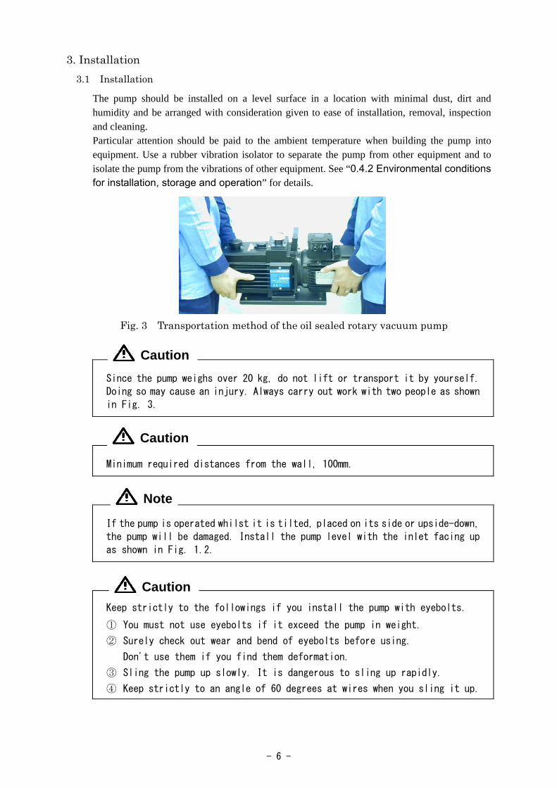
Fig. 3 Transportation method of the oil sealed rotary vacuum pump
Since the pump weighs over 20 kg, do not lift or transport it by yourself.
Doing so may cause an injury. Always carry out work with two people as shown
in Fig. 3.
Minimum required distances from the wall, 100mm.
If the pump is operated whilst it is tilted, placed on its side or upside-down,
the pump will be damaged. Install the pump level with the inlet facing up
as shown in Fig. 1.2.
Keep strictly to the followings if you install the pump with eyebolts.
① You must not use eyebolts if it exceed the pump in weight.
② Surely check out wear and bend of eyebolts before using.
Don't use them if you find them deformation.
③ Sling the pump up slowly. It is dangerous to sling up rapidly.
④ Keep strictly to an angle of 60 degrees at wires when you sling it up.
Note
Caution
Caution
Caution

- 7 -
3.2 Lubrication Remove the lubrication plug from the lubrication port, and add the pump oil which has been delivered together with the pump or the pump oil specified by us (SMR-100) up to the range marked with the line on the oil level gauge. When making the first lubrication, add oil near to the upper oil level limit shown on the oil level gauge. After lubrication, mount the lubrication plug to the pump (see Fig. 4). Always keep the oil level of the pump within the oil limit range shown on the oil level gauge during operation. If the amount of oil is incorrect, the performance of the pump will deteriorate resulting in the malfunctioning of the pump. When the amount of oil has reduced and the oil level has reached an area below the lower line which shows the lower limit on the oil level gauge such that the level cannot be seen, the ultimate pressure increases and exhausting sound may not cease. Remove rication plug from the lubrication port, and add the pump oil which has been delivered together with the pump or the pump oil specified by us (SMR-100) up to the range marked with the red line on the oil level gauge. When making the first lubrication, add oil near to the upper oil level limit shown on the oil level gauge. After lubrication, mount the lubrication plug to the pump (see Fig. 4). Always keep the oil level of the pump within the oil limit range shown on the oil level gauge during operation. If the amount of oil is incorrect, the performance of the pump will deteriorate resulting in the malfunctioning of the pump. When the amount of oil has reduced and the oil level has reached an area below the lower red line which shows the lower limit on the oil level gauge such that the level cannot be seen, the ultimate pressure increases and exhausting sound may not cease.
(1) Oil level shown on the oil level gauge (2) Lubrication method
Fig. 4 Lubrication of the oil sealed rotary vacuum pump
① Wear protective equipment such as rubber gloves and safety goggles.
② Be sure to read the attached “Material Safety Data Sheet” before adding
oil. If the oil accidentally comes into contact with your hands or enters
your eyes, take proper measures in accordance with the section “First-aid
treatment” shown in “Material Safety Data Sheet.”
Use only oils specified by us. If other oils are used, the pump performance
will deteriorate or its life will be shortened.
Note
Caution

- 8 -
3.3 Vacuum piping
(1) Before connecting the pipe to the pump, clean the inner walls of the vacuum chamber, piping and vacuum valve to completely eliminate moisture, fine particles, dust, dirt and rust.
If fine particles, dust or dirt, etc are evacuated, the pump may malfunction.
If moisture is evacuated, not only does the ultimate pressure increase but also
the inside of the pump becomes rusty causing the pump to malfunction.
(2) Mount vacuum valve (A) and leak valve (B) between the vacuum chamber and pump as shown in Fig. 5.
Fig. 5 Basic piping diagram to the vacuum chamber (3) Use a KF-25 (NW-25) flange for the connection to the inlet pipe.
The inlet filter in the inlet pipe has been adopted to prevent foreign matter
from entering the pump. Do not remove the inlet Filter.
Note
Vacu
um c
ham
ber
Vacuum valve (A)
Leak valve (B)
Pump
Note
- 9 -
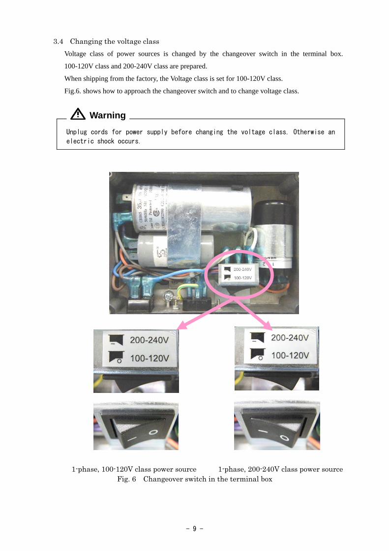
3.4 Changing the voltage class
Voltage class of power sources is changed by the changeover switch in the terminal box.
100-120V class and 200-240V class are prepared.
When shipping from the factory, the Voltage class is set for 100-120V class.
Fig.6. shows how to approach the changeover switch and to change voltage class.
Unplug cords for power supply before changing the voltage class. Otherwise an
electric shock occurs.
1-phase, 100-120V class power source 1-phase, 200-240V class power source Fig. 6 Changeover switch in the terminal box
Warning

- 10 -
3.5 Electric wiring
(1) The pump rotates in the clockwise direction as seen from the front of the pump (level gauge side).
(2) An inlet is suitable for standards of EN60320. (3) Insert an including plug cord into an Inlet as shown in fig.8. (4) Select an power cord which suitable for the voltage class. (5) An overload protector (auto reset thermal protector) is incorporated. (6) End-user has to make provisions for the installation of the over current protection of the
power circuit.
A start mode of this motor is condenser start / operating method. The switching
of the start / operation reaches by electronic governor switch. When I apply
voltage of the inverter control because I use an electron element for electronic
governor switch, malfunction of the electronic governor switch occurs and causes
the motor stumbling-block. Please never apply voltage of the inverter control.
Unplug cords for power supply before connecting wires. Otherwise an electric shock
occurs.
GROUNDING INSTRUCTIONS In the event of an electrical short circuit, grounding reduces the risk of electric shock by providing an escape wire for the electric current. This pump is equipped with a cord having a grounding wire with an appropriate grounding plug. The plug must be plugged into an outlet that is properly installed and grounded in accordance with all local codes and ordinances. If power code is not equipped (option) then appropriate grounding shall be provided upon installation.
Improper installation of the grounding plug is able to result in a risk of electric shock. When repair or replacement of the cord or plug is required, do not connect the grounding wire to either flat blade terminal. The wire with insulation having an outer surface that is green with or without yellow stripes is the grounding wire.
Check with a qualified electrician or serviceman when the grounding instructions are not completely understood, or when in doubt as to whether the product is properly grounded. Do not modify the plug provided; if it does not fit the outlet, have the proper outlet installed by a qualified electrician.
Note
Note
Warning
Warning
Warning

- 11 -
This pump must be connected to a grounded, metallic, permanent wiring system, or an equipment-grounding terminal or lead on the product.
Fig. 7 Electric wiring diagram
Fig. 8 An Inlet (EN60320)
Note

- 12 -
3.6 Fluctuations in the power voltage and frequency Standard: Rotation electricity machine general rules
IEC60034-1:2004 To the voltage change and frequency change in Domain A, in main rated values, it operates continuously, and can be used practically convenient, and to the voltage change and frequency change in Domain B, it shall operate with main rated values and shall be used practically convenient. However, operation with "it is convenient and safe is maintained on "practical use, it means not resulting in the grade which shortens a life remarkably, and the characteristic, a temperature rise, etc. do not apply correspondingly in the state of rating. Moreover, main rating shows rated torque (N・m).
Fig. 9 Change region of the voltage and frequency
Before connecting wires, turn off the power switch. Never perform wiring with the power supplied as an electric shock will occur. Connect the earth wire correctly. Failure to do so may result in electric shock if a failure or earth leakage occurs. Installation of a dedicated earth leakage breaker is also recommended.
Perform electric wiring correctly in accordance with the “Electric Equipment Technical Standard” and “Internal Wiring Regulation.” Incorrect wiring will result in fire.
Install an overload protector suitable for the capacity of the motor. If an overload protector is not installed, or if an overload protector that is unsuitable for the motor capacity is installed, the motor will be damaged leading to fire.
Caution
Warning
Caution

- 13 -
4. Operation 4.1 Cautions for operation
There is a risk of explosion. Never block the outlet or operate the pump with
equipment mounted at the outlet side which blocks the passage of gas.
Otherwise, the pump internal pressure increases causing the pump to explode,
the oil level gauge to protrude or the motor to be overloaded.
This pump is not resistant to pressure. The internal pump pressure is limited
to 0.03 MPa (gauge pressure).
① In the process of manufacturing semiconductors, pump oil may deteriorate
over a very short period of time. It is recommended that the pump oil should
be replaced within 10 days after starting use of the pump, and the
replacement frequency of the pump oil should be decided based on the
contamination level of the pump oil.
② If the pump evacuate a lot of moisture, replace the oil frequently. If
the pump is used with gas which contains a lot of moisture, water
absorption expands the vanes of the pump, the lubricity of the pump oil
deteriorates and corrosion of the pump’s components advance, causing the
pump to malfunction.
③ If chemicals including acid has been evacuated, the pump may become rusty
while it is not being operated (i.e. overnight), making operation
impossible. If such chemicals are evacuated, replace the pump oil
immediately.
④ Solvents which deteriorate the lubricity of the pump oil will cause
scoring, etc. If such a solvent is evacuated, replace the oil.
⑤ If operation is performed continuously at a high evacuation pressure of
10 kPa or more, a large amount of pump oil is consumed, causing a shortage
of oil and insufficient lubrication of the pump. If such a condition
continues, components will rapidly wear and become scored. Avoid
continuous operation at a high evacuation pressure as much as possible
and, without fail, add pump oil.
⑥ Do not block the flow of air to the motor fan as the temperature of the
motor and pump will increase.
Warning
Note

- 14 -
4.2 Start of operation To start operation, close leak valve (B), open vacuum valve (A) to the inlet port, and turn on the power switch. Then the pump starts beings to exhaust (see Fig. 5).
① The motor and pump become hot (temperature increase under non-load operation: 25K, temperature increase under high-load operation: 75K)
during operation of the pump. There is a risk of burns. Never touch the
motor or pump during operation.
② If operation is performed at high pressure, oil mist is generated at the
exhaust side. Install an oil mist trap or connect a duct to discharge the
oil mist outside the room. Or, install a ventilator.
When the pump does not rotate correctly, take the following measures.
a) Check the amount of oil, and adjust if necessary.
b) In an environment where the ambient temperature is low, if the pump is
left unused for a long time (three days or longer), the pump oil enters
the cylinder. (This phenomena cannot be avoided even if the pump pressure
is released to atmospheric pressure after last using the pump.) If the
pump is restarted in this condition, an overload is applied to the pump
and the overload protector may actuate. In such a case, turn the pump on
and off several times in short intervals.
The oil temperature in the pump increases 25 ~ 75K if operation continues
for several hours. If the oil temperature exceeds this range, there is a
possibility of the pump malfunctioning. Check the pump or contact us.
4.3 Stopping the operation To stop operation, close vacuum valve (A), open leak valve (B) quickly, and turn the power switch off (see Fig. 5). Please close a leak valve (B) and seal a suction side as much as possible, after making a suction side into atmospheric pressure.
The motor and pump become hot (temperature increase under non-load operation: 25K, temperature increase under high-load operation: 75K) during operation. There is a risk of burns. Never touch the motor or pump until they have cooled down completely after the pump is stopped.
Caution
Note
Note
Caution
- 15 -
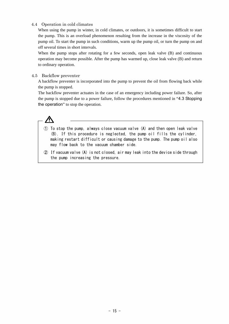
4.4 Operation in cold climates When using the pump in winter, in cold climates, or outdoors, it is sometimes difficult to start the pump. This is an overload phenomenon resulting from the increase in the viscosity of the pump oil. To start the pump in such conditions, warm up the pump oil, or turn the pump on and off several times in short intervals. When the pump stops after rotating for a few seconds, open leak valve (B) and continuous operation may become possible. After the pump has warmed up, close leak valve (B) and return to ordinary operation.
4.5 Backflow preventer
A backflow preventer is incorporated into the pump to prevent the oil from flowing back while the pump is stopped. The backflow preventer actuates in the case of an emergency including power failure. So, after the pump is stopped due to a power failure, follow the procedures mentioned in “4.3 Stopping the operation” to stop the operation.
① To stop the pump, always close vacuum valve (A) and then open leak valve
(B). If this procedure is neglected, the pump oil fills the cylinder,
making restart difficult or causing damage to the pump. The pump oil also
may flow back to the vacuum chamber side.
② If vacuum valve (A) is not closed, air may leak into the device side through
the pump increasing the pressure.

- 16 -
4.6 Thermal protector Auto reset thermal protector is incorporated in the motor in order to interrupt the power circuit
of the motor and prevent damage to the motor when an over current flows through the motor due to a stop in rotation or overload resulting from the pump malfunctioning during operation.
Table 2 Characteristics of the thermal protector
Operation temperature 120±5℃ Reset temperature 78±9℃
When the thermal protector has been actuated, turn off the switch and contact us. The motor is very hot when the thermal protector has actuated. Never touch it with your hand. When the cause of the malfunction has been eliminated, check that the motor has cooled down,
and restart operation (see “6.5 Trouble check list”).
The pump’s surface becomes hot (temperature increase under non-load operation: 25K, temperature increase under high-load operation: 75K). There is a risk of burns. Do not touch the motor or the main unit of the pump after the pump has stopped until it cools down completely.
4.7 Gas ballast valve The pump is equipped with a gas ballast valve in order to evacuate vapor and condensable gases such as solvent vapor. Evacuated condensable gas that liquefies in the compression and pressurization processes of the pump is mixed with the pump oil and starts circulating through the pump together with the oil. In such a case, the same effect as when oil of a high steam pressure is used is produced, and the ultimate pressure of the pump increases. Moreover, the lubricity of oil deteriorates and the service life of the shaft seal is shortened. If air or dry nitrogen enters through the gas ballast valve just before the compression and pressurization processes of the pump, condensable gas will not liquefy and will be exhausted together with air through the outlet valve. When the gas ballast valve is used, the “gas ballast effect” increases as the pump temperature becomes high. So, before evacuating condensable gas, perform operation for approximately 20 minutes with the gas ballast open, and after the pump temperature reaches approximately 50 ~ 65℃, open vacuum valve (A) and continue operation. If the temperature is low, a satisfactory “gas ballast effect” is not achieved. If the gas ballast valve is left open when condensable gas is not evacuated, not only does the pump oil scatter and power is lost, but also the ultimate pressure increases. Furthermore, since the gas ballast valve’s capacity to process condensable gas is limited, condensable gas remains in the pump oil when a lot of condensable gas is exhausted or when condensable gas (air and gas containing small amounts of moisture and other vapor which make the oil dirty) is exhausted without opening the gas ballast valve. In such a case, perform non-load operation with vacuum valve (A) closed and the gas ballast valve open. Then the oil temperature increases and the pump oil is purified due to the effect of the gas ballast valve. Continue non-load operation with the gas ballast valve closed until the specified pressure is reached. If the pump oil is not cleaned even a long time, replace the pump oil.
Caution
- 17 -
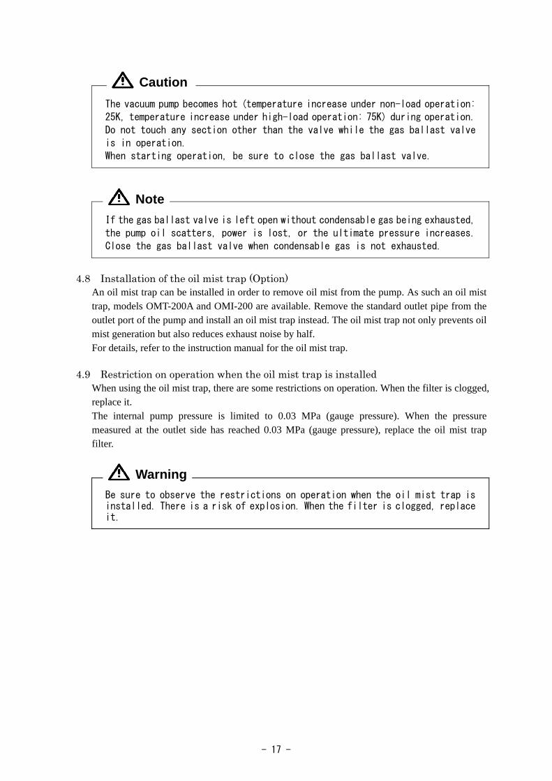
The vacuum pump becomes hot (temperature increase under non-load operation:
25K, temperature increase under high-load operation: 75K) during operation.
Do not touch any section other than the valve while the gas ballast valve
is in operation.
When starting operation, be sure to close the gas ballast valve.
If the gas ballast valve is left open without condensable gas being exhausted,
the pump oil scatters, power is lost, or the ultimate pressure increases.
Close the gas ballast valve when condensable gas is not exhausted.
4.8 Installation of the oil mist trap (Option)
An oil mist trap can be installed in order to remove oil mist from the pump. As such an oil mist trap, models OMT-200A and OMI-200 are available. Remove the standard outlet pipe from the outlet port of the pump and install an oil mist trap instead. The oil mist trap not only prevents oil mist generation but also reduces exhaust noise by half. For details, refer to the instruction manual for the oil mist trap.
4.9 Restriction on operation when the oil mist trap is installed
When using the oil mist trap, there are some restrictions on operation. When the filter is clogged, replace it. The internal pump pressure is limited to 0.03 MPa (gauge pressure). When the pressure measured at the outlet side has reached 0.03 MPa (gauge pressure), replace the oil mist trap filter.
Be sure to observe the restrictions on operation when the oil mist trap is installed. There is a risk of explosion. When the filter is clogged, replace it.
Caution
Note
Warning

- 18 -
5. Pump Performance 5.1 Ultimate pressure
The term “ultimate pressure” as employed in the catalogue and in this manual is defined as “the minimum pressure obtained by the pump without the introduction of gas from the pump inlet (i.e. the non-load condition).” For this pump, measurement is performed using the specified pump oil with only a Pirani vacuum gauge installed at the pump inlet port. Note that the Pirani gauge shows values approximately five to ten times higher than those shown by the McLeod gauge. This is because condensable gas components (mainly moisture) included in the measured air are removed when the McLeod gauge is used. Also, the actual ultimate pressure of the vacuum device becomes higher than that noted in the catalogue for the following reasons.
➀ The vacuum gauge is installed at a distance from the pump, and the steam and a variety of gases are generated by water droplets and rust on the inside walls of the pump and piping.
➁ Gasifying of volatile components which have dissolved in the pump oil. (Deterioration of pump oil)
➂ Existence of a gas supply source including vacuum leakage in the vacuum path.
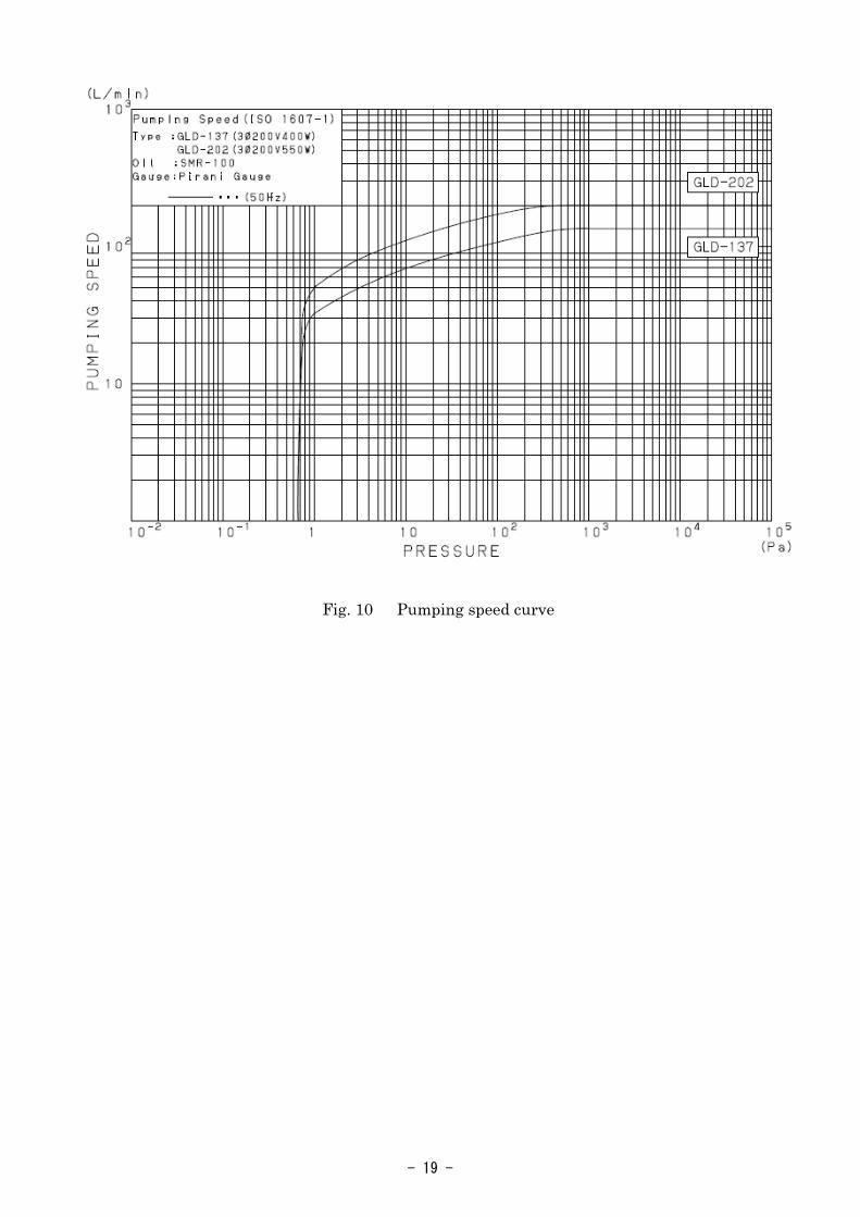
5.2 Pumping speed The pumping speed of the pump depends on the type and pressure of the gas to be evacuated. The pumping speed usually reaches the maximum at a high pressure range, and it gradually decreases as the pressure reduces. The nominal pumping speed of this pump is the maximum pumping speed when dry air is evacuated. Fig. 10 shows the relationship between the evacuation pressure and pumping speed.
5.3 Power requirement The power required to operate the pump is the total of the power required to overcome the rotational resistance of the pump (mechanical work) and the power required to compress the air (compression work), and reaches a maximum at an inlet evacuation pressure of around 2.7×10⁴
to 4×10⁴ Pa. If the inlet evacuation pressure has reduced to 13.3 Pa or less, the compression work is considerably reduced and more power is consumed in mechanical work.
- 19 -
Fig. 10 Pumping speed curve

- 20 -
6. Maintenance, Inspection and Repair 6.1 Maintenance
Check the following during operation at least once every three days. (1) Amount of pump oil (To be within the range shown with red lines on the oil level gauge) (2) Discoloration of the pump oil (3) Abnormal sound (4) Problem with the motor current value (5) Oil leak from the oil seal If there is any problem, take proper measures in accordance with “6.5 Trouble check list.”
6.2 Periodic inspection The items to be checked should be changed as necessary depending on the environment where the pump is used. However, always check the following in order to prevent a malfunction and to lengthen the service life of the pump.
① Pulled out the power plug before starting inspection and do not turn it on while inspection is in progress. Doing so will result in injury.
② The pump is very hot immediately after it is stopped. Wait for 10 minutes
until the pump has cooled down completely and then start inspection. There
is a risk of burns.
1) Periodic replacement of the pump oil The pump oil deteriorates with operation. Check the viscosity and level of contamination of
the pump oil with the oil level gauge, and replace the pump oil in good time. If the pump oil is replaced periodically, the deterioration of the pump oil is minimized and the service life of the pump is lengthened.
If operation is continued with a lot of moisture mixed with the pump oil, the ultimate pressure will not reach the standard value, the movement at the section where the mechanical friction is generated becomes slow, and the pump finally becomes damaged. Replace the pump oil in accordance with “6.3 Replacement of the pump oil.”
Caution

- 21 -
Table 3 Periodic inspection table
Frequency Item Details Measures Amount Refill the oil. Oil Color (Reddish brown, dark blown, and cloudy white are not good.)
Replace the oil.
Sound Abnormal sound Vibration Abnormal vibration
Check nuts and bolts for looseness. If not clear, contact us.
Once/3 days
Current value
Difference from the rated value Check the cause of an overload. If not clear, contact us.
Surface temperature
Surface temperature (The temperature higher than the room temperature by 75K or more is abnormal.)
Check the cause of an overload. If not clear, contact us.
Once/week
Oil leakage Oil leakage from the shaft seal section and plugs.
Replace seals, or contact us.
Inlet Filter Clogged with dust Clean the wire mesh. Once/3,000 operation hours or once/6 months
Oil Even if no problem is recognized, be sure to replace the oil.
Replace the oil.
Once/year Spider Damage or fracture Replace the spider. 2) Inspection of the amount of pump oil Refill the pump oil so that the pump oil level is kept within the range of the red lines
showing the upper and lower limits on the oil level gauge during operation. 3) Inspection of oil leakage When oil leaks from the shaft seal section or drain plug seal section, repair is required. Our
specified O-rings and seals are always available from the service departments shown at the back of this manual. When necessary, contact them.
4) Inspection of inlet filter If the wire mesh is clogged with dust included in the evacuated gas, the pump’s efficiency
may deteriorate. 5) Inspection of abnormal sounds and vibration Check the nuts and bolts for looseness.

- 22 -
6) Inspection of the coupling spider Check the spider of the coupling which connects the main pump unit and motor of the pump
for damage. If cracks or fractures are found on the spider, replace it in accordance with “6.4 Replacement of the coupling spider.”
7) Inspection of the oil mist trap When using the oil mist trap in replacement of the standard outlet pipe, pay attention to the
clogging of the filter in the oil mist trap. If the clogging advances, evacuated gas cannot be exhausted any longer, which causes the oil gauge to protrude and oil leakage from the shaft seal section or drain plug seal section. The maximum internal pump pressure is 0.03 MPa (gauge pressure).
When the pump is operated continuously for a long time or when the pump is extremely
contaminated with evacuated gas, overhaul is required. Contact the nearest sales or service department among those listed at the back of this manual.
When requesting the manufacturer’s service department to overhaul the pump,
always write the type of the vacuumed gas on the “Pump Usage Check Sheet”
attached at the back of this manual and submit it. Note that if toxic gases are
exhausted, both the pump itself and pump oil will become contaminated. Please
be sufficiently aware that use with some gases will preclude overhaul.
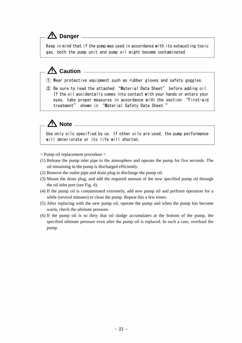
6.3 Replacement of the pump oil The pressure of the vacuum device may increase due to the deterioration of the pump oil. In such a case, close the inlet port of the pump and check that the specified ultimate pressure has been reached. If not, replace the pump oil. If substances having a high vapor pressure (such as moisture or solvents) are mixed with the pump oil, or if sludge is accumulated at the bottom of the pump, the ultimate pressure cannot be reached with only one replacement and the pump oil must be replaced several times. The deterioration of the pump oil is caused not only by the contamination due to evacuated gas but also by the changes in the properties of the pump oil itself (depending on the operation time). Periodic replacement in accordance with Table 3 showing an oil replacement guide is recommended.
Danger
- 23 -
Keep in mind that if the pump was used in accordance with its exhausting toxic
gas, both the pump unit and pump oil might become contaminated.
① Wear protective equipment such as rubber gloves and safety goggles.
② Be sure to read the attached “Material Data Sheet” before adding oil.
If the oil accidentally comes into contact with your hands or enters your
eyes, take proper measures in accordance with the section “First-aid
treatment” shown in “Material Safety Data Sheet.”
Use only oils specified by us. If other oils are used, the pump performance
will deteriorate or its life will shorten.
< Pump oil replacement procedure > (1) Release the pump inlet pipe to the atmosphere and operate the pump for five seconds. The
oil remaining in the pump is discharged efficiently. (2) Remove the outlet pipe and drain plug to discharge the pump oil. (3) Mount the drain plug, and add the required amount of the new specified pump oil through
the oil inlet port (see Fig. 4). (4) If the pump oil is contaminated extremely, add new pump oil and perform operation for a
while (several minutes) to clean the pump. Repeat this a few times. (5) After replacing with the new pump oil, operate the pump and when the pump has become
warm, check the ultimate pressure. (6) If the pump oil is so dirty that oil sludge accumulates at the bottom of the pump, the
specified ultimate pressure even after the pump oil is replaced. In such a case, overhaul the pump.
Danger
Caution
Note

- 24 -
6.4 Replacement of the coupling spider A rubber spider is used at the section connecting the pump main unit and the motor. It is
recommended that this spider be periodically inspected once a year or so. If the corner is chipped or cracked, replace it. If the pump is started and stopped hundreds of times a day, increase the inspection frequency.
To take out the spider, remove the four bolts which fix the motor to the pump main unit, and remove the motor. Then the coupling can be removed and the spider taken out. After inspecting the spider, mount the spider to either of the two coupling, and adjust the position so that both claws of the couplings are engaged with each other as shown in Fig. 11.
Fig. 11 Replacement of the coupling spider Connect the concave section (female) of the pump unit with the convex section (male) of the
motor, push the motor into the pump so that both connecting surfaces come completely into contact with each other, and fix the motor with bolts.

- 25 -
6.5 Trouble check list
Table 4 Trouble check list Problem Cause Measures Reference
① The pump is not connected to the power supply.
① Connect the pump to the power supply.
3.5
② The power switch is not turned on. ② Turn on the power switch. 4.2 ③ Problem with power supply voltage ③ Set the power supply voltage to
within ±10% of the rated voltage. 3.6
④ The overload protector has actuated.
④Wait till the temperature goes down to 78 ± 9℃.
4.6
⑤ The motor malfunctions. ⑤ Replace the motor. ⑥ Low ambient temperature has
increased the oil viscosity. ⑥ Increase the ambient temperature to
7℃ or more. 4.4
⑦ The entrance of foreign matter into the pump caused the rotor to burn out.
⑦ Overhaul (replace the cylinder and rotor).
6.2
⑧ Moisture or solvents were sucked in, forming rust inside the pump.
⑧ Overhaul (replace the cylinder and rotor).
6.2
⑨ Reaction product accumulated in the pump when the pump stops after exhausting reactive gas.
⑨ Overhaul (clean the pump inside and remove reaction products).
⑩Water absorption expands the vanes. ⑩Overhaul (replace the vanes)
The pump does not rotate.
⑪ Components inside the pump have burnt out.
⑪ Overhaul (replace the damaged components).
① Problem with power supply voltage ① Set the power supply voltage to within ±10% of the rated voltage.
3.6
② Defective wiring to the pump ② Perform wiring to the pump again. 3.5 ③ Low ambient temperature has
increased the oil viscosity. ③ Increase the ambient temperature to
7℃ or more. 4.4
The pump’s rotation is unstable.
④ Foreign matter has entered the pump.
④ Disassemble and clean the pump to eliminate foreign matter.
① The pump is too small for the volume of the vacuum chamber.
① Select another pump. 5.2
② The pressure measurement method is not correct.
② Measure the pressure correctly. 5.1
③ The vacuum gauge is not suitable. ③ Measure with a calibrated vacuum gauge suitable for the pressure range.
④ The pipe connected to the inlet port is small, or the piping distance is long.
④ Use pipes having a diameter larger than the inlet port diameter, or reduce the distance from the vacuum chamber.
5.1
The pressure does not decrease.
⑤ The wire mesh at the inlet port is clogged.
⑤Remove the piping from the upper section of the inlet port, and clean the wire mesh.
6.2

- 26 -
Problem Cause Measures Reference
⑥ The specified amount of oil has not been added.
⑥ Add the specified amount of oil. 3.2
⑦ The oil has deteriorated. ⑦ Replace the oil. 6.3 ⑧ Leakage occurs from the pipe
connected to the pump. ⑧ Locate the leakage with a leakage
detector and stop the leakage.
⑨ Our specified oil is not being used. ⑨ Overhaul the pump and replace with oil specified by us
6.3
The pressure does not decrease.
⑩ Oil does not circulate, or the oil hole of the cover is clogged.
⑩ Overhaul and clean the oil hole. 6.2
① Problem with power supply voltage ① Set the power supply voltage to within ±10% of the rated voltage.
3.6
② The motor malfunctions. ② Replace the motor. ③ Foreign matter has entered the
pump. ③ Eliminate the foreign matter and
overhaul the pump.
④ The specified amount of oil has not been added.
④ Add the specified amount of oil. 3.2
⑤ The coupling spider malfunctions. ⑤ Replace the coupling spider. 6.4 ⑥ Oil does not circulate, or the oil
hole of the cover is clogged. ⑥ Overhaul and clean the oil hole. 6.2
Abnormal sound is generated.
⑦ Components inside the pump have burnt out.
⑦ Overhaul (replace the damaged components).
① Continuous operation at high evacuation pressure
① If continuous operation is performed at a high evacuation pressure, the pump surface temperature increasing 75K.
Under 75K temperature increasing is not a serious problem.
② The specified amount of oil has not been added. (If the oil amount is not sufficient, the cooling effect of the pump will be reduced.)
② Add the specified amount of oil. 3.2
③ The temperature of the evacuated gas is high.
③ Mount cooling equipment such as a gas cooler at the inlet side.
Pump surfaces are extremely hot
④ Oil does not circulate, or the oil hole of the cover is clogged.
④ Overhaul and clean the oil hole. 6.2
① The pump is been filled in excess of the specified amount.
① Discharge the oil until it reduces to the specified amount.
3.2 A lot of oil splashes out from the outlet port.
② Continuous operation is performed at a high evacuation pressure.
② Install an oil mist trap at the outlet side.
4.8
The oil leaks outside the pump.
① Deterioration of the O-ring and the oil seal of the case and cover
① Check and replace the O-ring and oil seal.
6.2

- 27 -
7. Disposal Follow state law and local government regulations for disposal of the pump.
① In case a harmful toxic gas has been exhausted by accident, ask a
specialist for waste disposal. Not only the pump itself but also the pump
oil become toxic.
② For the disposal of pump oil, follow the instructions given under “Cautions for disposal” in “Material Safety Data Sheet.”
③ Delegate the disposing of inlet filters to venders for waste disposal.
Caution
- 28 -
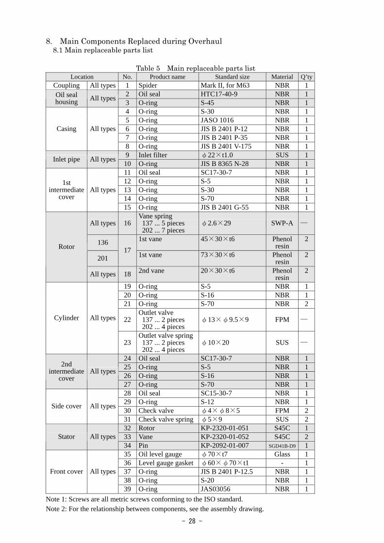
8. Main Components Replaced during Overhaul 8.1 Main replaceable parts list
Table 5 Main replaceable parts list
Location No. Product name Standard size Material Q’ty Coupling All types 1 Spider Mark II, for M63 NBR 1
2 Oil seal HTC17-40-9 NBR 1 Oil seal housing All types 3 O-ring S-45 NBR 1
4 O-ring S-30 NBR 1 5 O-ring JASO 1016 NBR 1 6 O-ring JIS B 2401 P-12 NBR 1 7 O-ring JIS B 2401 P-35 NBR 1
Casing All types
8 O-ring JIS B 2401 V-175 NBR 1 9 Inlet filter φ22×t1.0 SUS 1 Inlet pipe All types 10 O-ring JIS B 8365 N-28 NBR 1 11 Oil seal SC17-30-7 NBR 1 12 O-ring S-5 NBR 1 13 O-ring S-30 NBR 1 14 O-ring S-70 NBR 1
1st intermediate
cover All types
15 O-ring JIS B 2401 G-55 NBR 1
All types 16 Vane spring 137 ... 5 pieces 202 ... 7 pieces
φ2.6×29 SWP-A ─
136 1st vane 45×30×t6 Phenol resin
2
201 17 1st vane 73×30×t6 Phenol
resin 2
Rotor
All types 18 2nd vane 20×30×t6 Phenol resin
2
19 O-ring S-5 NBR 1 20 O-ring S-16 NBR 1 21 O-ring S-70 NBR 2
22 Outlet valve 137 ... 2 pieces 202 ... 4 pieces
φ13×φ9.5×9 FPM ─ Cylinder All types
23 Outlet valve spring 137 ... 2 pieces 202 ... 4 pieces
φ10×20 SUS ─
24 Oil seal SC17-30-7 NBR 1 25 O-ring S-5 NBR 1 26 O-ring S-16 NBR 1
2nd intermediate
cover All types
27 O-ring S-70 NBR 1 28 Oil seal SC15-30-7 NBR 1 29 O-ring S-12 NBR 1 30 Check valve φ4×φ8×5 FPM 2 Side cover All types
31 Check valve spring φ5×9 SUS 2 32 Rotor KP-2320-01-051 S45C 1 33 Vane KP-2320-01-052 S45C 2 Stator All types34 Pin KP-2092-01-007 SGD41B-D9 1 35 Oil level gauge φ70×t7 Glass 1 36 Level gauge gasket φ60×φ70×t1 - 1 37 O-ring JIS B 2401 P-12.5 NBR 1 38 O-ring S-20 NBR 1
Front cover All types
39 O-ring JAS03056 NBR 1 Note 1: Screws are all metric screws conforming to the ISO standard. Note 2: For the relationship between components, see the assembly drawing.

- 29 -
8.2 Disassembly drawing
Fig. 12 Disassembly drawing of GLD-137CC/202BB oil sealed rotary vacuum pump

Warranty
(1) The warranty for this pump extends for a period of one year from the date of shipment.
(2) Any malfunctions or defects which occur under normal usage conditions during the warranty
period will be repaired free of charge.
Note, the warranty stated here is an individual warranty covering the pump. In addition, the
scope of the warranty coverage concerning repairs is limited to the repair and/or replacement of
parts.
Normal usage conditions refer to the following:
a) Ambient temperature and humidity during operation: 7 - 40°C, below 85% RH
b) Operation in accordance with the user manual
(3) Repair fees will incur during the warranty period for the following cases:
a) Malfunctions due to a natural disaster or fire.
b) Malfunctions caused by special atmospheric conditions, such as salt damage, inflammable
gas, corrosive gas, radiation or pollution.
c) Malfunctions caused by usage conditions that differ from those stated in the user manual
(performance specifications, maintenance and inspection, etc.).
d) Malfunctions caused by modifications or repairs carried out by a party other than the
manufacturer, or by a service company not approved by the manufacturer.
e) Malfunctions caused by noise (electric disturbance).
f) Malfunctions that occur when not using a rated power supply.
g) Malfunctions that occur when there is an abnormal rise in internal pressure due to the pump
exhaust outlet being blocked during operation, etc.
h)Malfunctions that occur, when the pump is damaged as a result of being dropped or falling,
etc.
i) Malfunctions which are determined by the manufacturer’s technical personnel to be caused
by conditions that do not comply with the usage conditions for this vacuum pump.
j) Malfunctions due to the replacement of consumables.
(4) Disclaimer
a) We shall not be liable for any malfunctions of our products caused by the customer,
regardless if the malfunction does not fall within the warranty period, nor shall we be liable
for any loss of opportunity for the customer’s clients or for compensation for any damages to
other products, labor costs, production loss, transportation expenses and other related
work.
b) We shall not be liable for any claims and patent infringements, including secondary
damages, filed a claim by a third party against the customer.
Date Prepared: May 19, 2015 1KE
1/7
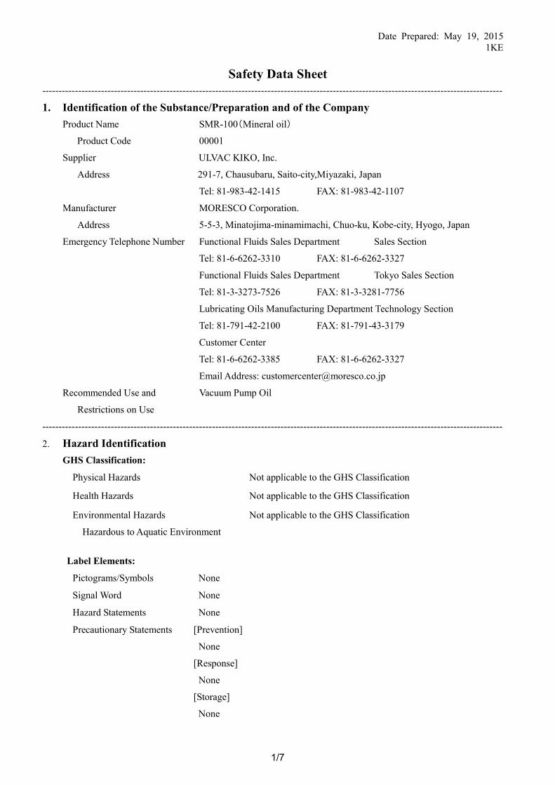
Safety Data Sheet --------------------------------------------------------------------------------------------------------------------------------------------- 1. Identification of the Substance/Preparation and of the Company
Product Name SMR-100(Mineral oil)
Product Code 00001
Supplier ULVAC KIKO, Inc.
Address 291-7, Chausubaru, Saito-city,Miyazaki, Japan
Tel: 81-983-42-1415 FAX: 81-983-42-1107
Manufacturer MORESCO Corporation.
Address 5-5-3, Minatojima-minamimachi, Chuo-ku, Kobe-city, Hyogo, Japan
Emergency Telephone Number Functional Fluids Sales Department Sales Section
Tel: 81-6-6262-3310 FAX: 81-6-6262-3327
Functional Fluids Sales Department Tokyo Sales Section
Tel: 81-3-3273-7526 FAX: 81-3-3281-7756
Lubricating Oils Manufacturing Department Technology Section
Tel: 81-791-42-2100 FAX: 81-791-43-3179
Customer Center
Tel: 81-6-6262-3385 FAX: 81-6-6262-3327
Email Address: [email protected]
Recommended Use and Vacuum Pump Oil
Restrictions on Use
--------------------------------------------------------------------------------------------------------------------------------------------- 2. Hazard Identification
GHS Classification:
Label Elements:
Pictograms/Symbols None
Signal Word None
Hazard Statements None
Precautionary Statements
[Prevention]
None
[Response]
None
[Storage]
None
Physical Hazards Not applicable to the GHS Classification
Health Hazards Not applicable to the GHS Classification
Environmental Hazards
Hazardous to Aquatic Environment
Not applicable to the GHS Classification

Date Prepared: May 19, 2015 1KE
2/7
[Disposal]
None
---------------------------------------------------------------------------------------------------------------------------------------------
3. Composition/Information on Ingredients Distinction between Substance and Mixture : Substance Chemical Name/Generic Name : Petro-hydrocarbons
Chemical Formula : Not identified
Ingredient and Concentration Lubricating base oil 100%
-----------------------------------------------------------------------------------------------------------------------------------------------
4. First-Aid Measures Inhalation: Remove victim to fresh air and let him rinse mouth thoroughly with water.
Wrapping a blanket and the like around him to keep warm for a rest, call a
doctor/physician immediately.
Skin Contact: Rinse skin with soap and water.
Eye Contact: Immediately rinse eyes with clean water for at least 15 minutes. Remove
contact lenses if present. Continue rinsing. If eye irritation persists, get medical
attention.
Ingestion: Call a doctor/physician immediately. Do not induce vomiting.
If affected, the mouth should be rinsed out thoroughly with water.
Expected Acute and If swallowed, may suffer from diarrhea and vomiting.
Delayed Symptoms, and May cause inflammation if in eyes.
Most Important Symptoms/ May cause inflammation if on skin.
Effects: May feel unwell if mist is inhaled.
------------------------------------------------------------------------------------------------------------------------------------------------
5. Fire-Fighting Measures Suitable Extinguishing Media Foggy reinforcing agent, foam, powder, or carbon dioxide
Unsuitable Extinguishing Media Jet water
Specific Hazards Currently there is no useful information.
Specific Fire-Fighting Measures Shut off the fire source.
Use powder or carbon dioxide extinguishers at the beginning of fire.
It is effective to intercept the air from a big fire with foam
extinguishers. Use of water may cause spreading of fire.
Cool the surrounding facilities with water spray.
Evacuate non essential personnel around the fire.
Special Protective Actions for
Fire-Fighting
Wearing protective glasses, protective clothing, and if necessary,
respiratory protective equipment, start to fight fire on the windward
side.
------------------------------------------------------------------------------------------------------------------------------------------------

Date Prepared: May 19, 2015 1KE
3/7
6. Accidental Release Measures Personal Precautions, Protective
Equipment and Emergency Procedures If skin or eye contact is possible, wear protective equipment. If mist
is produced, wear respiratory protective equipment to avoid
inhalation. Environmental Precautions Take up as much as possible to avoid soil contamination and water
pollution.
Avoid release to the environment. Collection/Neutralization
and Methods/Materials for Containment Eliminate the source of ignition of the surrounding.
In the case of a large amount: Dike ahead of liquid spill area to
minimize migration and then sweep into an empty container for
disposal in a safe place. After disposal, wash away with plenty of
water. In doing so, take care to prevent the high concentration of
wastes from entering public watercourses such as rivers.
In the case of a small amount: Take up into an empty container by
absorbing the spill with earth and sand or rags, and furthermore sop
up with rags thoroughly. Prevention of Secondary Hazards Remove all the ignition sources immediately. (Do not smoke nearby
and keep away from sparks and flames.)
Report to the related organs for help. ------------------------------------------------------------------------------------------------------------------------------------------------
7. Handling and Storage Handling:
Technical Measures
Before repairing machinery with remnant oils on, remove them
thoroughly in a safe place. Take precautionary measures against
static discharge and wear electro conductive clothing and shoes.
As vapors released from petroleum products are heavier than air,
they are liable to stagnate.
Due to it, attention should be paid to ventilation and fire.
Handle at room temperatures, paying attention to moisture and to
impurities not to mix with.
If skin or eye contact is possible, wear protective equipment. If mist
is produced, wear respiratory protective equipment to avoid
inhalation.
Use a pump and the like to take out of container.
Do not suck through a tube.
Do not weld, heat, hole, and cut off the container. Residues may
ignite involving explosion.
Local Exhaust Ventilation/
Full Ventilation System
Refer to ‘8. Exposure Controls/Personal Protection’.
Avoiding Contact Refer to ’10. Stability and Reactivity’.

Date Prepared: May 19, 2015 1KE
4/7
Precautions for Safe Handling Obtain special instructions before use.
Do not handle until all safety precautions have been read and
understood.
Be cautious not to use any naked fire.
As vapors released from petroleum products are heavier than air,
they are liable to stagnate.
Wash hands thoroughly after handling.
Use only outdoors or in a well-ventilated area.
Do not eat, drink or smoke when using this product.
Do not press an empty container. It may explode under pressure.
Do not drink.
Keep out of reach of children.
Storage:
Technical Measures
Avoid heat, sparks, flames, and static electricity.
Keep container tightly closed.
Incompatible Materials Refer to ’10. Stability and Reactivity’.
Conditions for Safe Storage Store in a well-ventilated area.
Store avoiding exposure to direct sunlight.
Store away from oxidizer.
Store locked up.
Materials for Containers/Packaging When replacing the container, use metal or glass container. Some
kinds of resin-treated container may melt.
Use airtight, anti-breakage type containers.
------------------------------------------------------------------------------------------------------------------------------------------------
8. Exposure Controls/Personal Protection Permissible Concentration (Exposure Limit, a biological exposure index):
Japan Society for Occupational Health (2010):
ACGIH (2010):
3mg/m3 (mineral oil mist) 1)
TWA 5mg/ m3 (mineral oil mist) 2)
Standards for Allowable Density of Hazardous Substances in Labor Operation Air: Not established
Engineering Controls: When mist and vapors are produced, seal off sources or provide exhaust
ventilation. Facilities for rinsing eyes and washing a body are required near the
workplace.
Personal Protective Equipment
Respiratory Protection:
Hand Protection:
Eye Protection:
Skin and Body Protection:
Wear appropriate respiratory protection.
If necessary, wear oil-resistant protective gloves.
If diffusion is possible, wear eye protection.
If necessary, wear protective clothing and face protection.
Hygienic Precautions: Wash hands thoroughly after handling.
Regularly inspect protective equipment according to the inspection table of

Date Prepared: May 19, 2015 1KE
5/7
protective equipment.
Do not eat, drink or smoke when using this product.
------------------------------------------------------------------------------------------------------------------------------------------------
9. Physical and Chemical Properties Physical State:
Appearance
Color
Odor
pH
Melting/Freezing Point
Boiling Point
Flash Point
Explosive Range (Explosive Limits)
Vapor Pressure
Vapor Density (air=1)
Specific Gravity (Density)
Solubility
Partition Coefficient: n-octanol/water
Auto-ignition Temperature
Pour point
Volatility
Liquid
Light yellow
Slight Oily odor
Not applicable
Not applicable
165℃/13Pa(0.1mmHg)
≧200℃(COC)
Upper limit: 7% Lower limit: 1% (estimated value)
No data available
No data available
0.88g/cm3 (15℃)
Insoluble in water
No data available
No data available
≦-15℃
None (at room temperatures)
------------------------------------------------------------------------------------------------------------------------------------------------
10. Stability and Reactivity Stability Stable
Possibility of Hazardous Reactions Reacts with strong oxidizer.
Conditions to Avoid No data available (Hazardous reactions will not occur under normal
use)
Incompatible Materials Strong oxidizer
Hazardous Decomposition Products None
--------------------------------------------------------------------------------------------------------------------------------------------
11. Toxicological Information Acute Toxicity:
Oral
Dermal
Inhalation
Skin Corrosion/Irritation
Serious Eye Damage/Eye Irritation
Respiratory or Skin Sensitization
Germ Cell Mutagenicity
ATEmix(Oral)>5000mg/kg
ATEmix(Dermal)>5000mg/kg
ATEmix(Inhalation)>5mg/L
Information is not classified as Skin Corrosion/Irritation.
Information is not classified as Serious Eye Damage/Eye Irritation.
Information is not classified as Respiratory or Skin Sensitization.
Information is not classified as Germ Cell Mutagenicity.

Date Prepared: May 19, 2015 1KE
6/7
Carcinogenicity
Reproductive Toxicity
STOT/Systemic Toxicity -
Single Exposure
STOT/Systemic Toxicity –
Repeated Exposure
Aspiration Hazard
Information is not classified as Carcinogenicity.
Information is not classified as Reproductive Toxicity.
Information is not classified as Specific Target Organ Toxicity/
Systemic Toxicity (Single Exposure).
Information is not classified as Specific Target Organ Toxicity/
Systemic Toxicity (Repeated Exposure).
Information is not classified as Aspiration Hazard.
------------------------------------------------------------------------------------------------------------------------------------------------
12. Ecological Information Ecotoxicity Information is not classified as Aquatic Toxicity.
Persistence and Degradability
Bioaccumulative Potential
Mobility in Soil
Hazardous to the ozone layer
Other Adverse Effects
Environmental Criteria
No information available
No information available
No information available
No information available
No information available
No information available
------------------------------------------------------------------------------------------------------------------------------------------------ 13. Disposal Considerations
Waste Residues Dispose the waste according to national and local regulations.
Do not dump.
Contaminated Containers Contaminated or empty container/packaging are to be disposed according to
and Packaging national and local regulations.
------------------------------------------------------------------------------------------------------------------------------------------------
14. Transport Information International Regulation
UN Classification
Not applicable
Special Precautions Load the containers in a manner that they are certain not to result in direct
sunlight exposure, damage, corrosion, leak, while being transported.
Do not place heavy load on top of the container.
------------------------------------------------------------------------------------------------------------------------------------------------
15. Regulatory Information No Information
------------------------------------------------------------------------------------------------------------------------------------------------
16. Other Information References: 1) Recommendation of Occupational Exposure Limits by Japan Society for Occupational Health
2) Thresholds limit values for chemical substances and physical agents and biological exposure
indices by ACGIH
3) SDS of raw materials
Date Prepared: May 19, 2015 1KE
7/7
1. As evaluations on hazards are not necessary satisfactory, special attention should be paid for use.
2. This SDS, summarizing matters to be attended to, is required for proper use of the product and is intended for
normal use.
3. Referring to this SDS, properly use and handle this product on the user’s own responsibility.
4. The contents of this SDS are based on information available as of today and our knowledge. The information,
data, and evaluations herein are not guaranteed, and in addition, may be revised due to revision of laws or
knowledge newly obtained.

Usage Status Check Sheet (for use in Operation Manual)
* For the purpose of safety control of repair personnel, fill in within the heavy line frame and attach the sheet to the item of which repair is requested. * In case this sheet were not attached or filled in, your request of repair and service may not be accepted. * In accordance with the Private Information Protection Law, the provided information will be used only for determining the cause of failure and whether detoxifying washing should be conducted. It will never be provided to any third person.
Model Name: _______________ Manufacturer’s Serial No.:________________
1. Inhaled Gas * Please be sure to fill in. (1) Whether there is harmful effect on human bodies Yes No (Sing your name below.) (2) Whether there is unusual smell Yes No (3) Type and Name of Gas:______________________________ * Industrial Safety and Health Law designates particular substances as the materials to be notified. 2. Usage Status Operation Method: Approx. ( ) hours per day, ( ) years and ( ) months □ Continuous Operation □ Intermittent Operation Usage:__________________________________ 3. Failure Status □Unusual Noise □Abnormal Pressure □Abnormal Actuation
□Oil Leakage Other Symptoms:_______________________________
4. Detail of Request □Repair (Overhaul) □Regular Checks 5. Others:_____________________________ Company Name: Personnel in charge: Address: Tel: Fax: E-mail: Agent Name; Personnel in charge: Address: Tel: Fax: * In case you do not have any direct transaction with us, please be sure to fill in the agent name. 6. Confirmation The gas and substance used in this pump or unit is harmless to human bodies, or it is not contaminated by any substance harmful to human bodies. Signed (seal) Date: * In order to avoid a trouble during transportation, please evacuate oil from any oil pump before shipping.
* You are requested to ship the package to our Service Division (CS Center). (See the attached list of addresses.)

No.62400-2-02-4
Sales, service agency, and the where to make contact
<Sales Office> Sales Division & Overseas Division & Yokohama Branch
1-10-4, Kitashinyokohama, Kohoku-ku, Yokohama-shi, Kanagawa Prf. Japan
Yokohama branch: TEL (81) 45-533-0203 FAX (81) 45-533-0204
Overseas Division: TEL (81) 45-533-0206 FAX (81) 45-533-0204
Osaka Branch
3-3-31 Miyahara, Yodogawa-ku, Osaka-shi, Osaka-fu Japan
TEL(81)6-6350-2166 FAX(81)6-6350-2169
Nagoya Branch
3-11-31 Sakae, Naka-ku, Nagoya-shi, Aichi Prf. Japan
TEL(81)52-249-5121 FAX(81)52-249-5122
<Service Office> Yokohama Branch
1-10-4, Kitashinyokohama, Kohoku-ku, Yokohama-shi, Kanagawa Prf. Japan
TEL(81)45-533-0509 FAX(81)45-533-0512
Miyazaki Branch
291-7 Chausubaru, Saito-shi, Miyazaki Prf. Japan
TEL(81)983-42-4135 FAX(81)983-43-2159
ULVAC GmbH
Parkring 11, 85748, Garching, Germany
TEL(49)89-96-0909-0 FAX(49)89-96-0909-96
ULVAC KIKO,Inc. www.ulvac-kiko.com
HEAD OFFICE/ Miyazaki Plan
291-7 Chausubaru, Saito-shi, Miyazaki Prf. Japan
TEL : (81)983-42-1411
FAX : (81) 983-42-1422