instruction manual - forsíða · vlt® 2800 series introduction to vlt 2800 vlt 2800 series...
TRANSCRIPT

VLT® 2800
Instruction Manual


VLT® 2800 Series
■ Contents
Introduction to VLT 2800 ............................................................................... 3Software version ....................................................................................................... 3High voltage warning ................................................................................................ 5These rules concern your safety ............................................................................... 5Warning against unintended start ............................................................................. 5
Installation ........................................................................................................... 6Mechanical dimensions ............................................................................................ 6Mechanical installation ............................................................................................ 10General information about electrical installation ...................................................... 11EMC-correct electrical installation ........................................................................... 12Grounding of shielded/armoured control cables ..................................................... 13Diagram ................................................................................................................. 14Electrical installation ............................................................................................... 15Safety clamp .......................................................................................................... 17Input fuses ............................................................................................................. 17AC line connection ................................................................................................. 17Motor connection ................................................................................................... 17Direction of motor rotation ...................................................................................... 17Motor thermal protection ........................................................................................ 17Parallel connection of motors ................................................................................. 18Motor cables .......................................................................................................... 18Brake connection ................................................................................................... 18Ground connection ................................................................................................ 18Load sharing .......................................................................................................... 19Tightening Torque, Power Terminals ....................................................................... 19Calculation of brake resistance ............................................................................... 19Access to control terminals .................................................................................... 19Electrical installation, control circuitry ...................................................................... 20Tightening torques, control cables .......................................................................... 21Electrical installation, control terminals .................................................................... 21Relay connection .................................................................................................... 21VLT Software Dialog ............................................................................................... 22Connection examples ............................................................................................. 23Control unit ............................................................................................................ 25Manual initialization ................................................................................................. 25Automatic motor tuning .......................................................................................... 26Display readout ...................................................................................................... 28Hand / Auto mode operation .................................................................................. 28Warnings/alarms .................................................................................................... 29Special conditions .................................................................................................. 30Temperature-related switching frequency ............................................................... 30Derating for long motor cables .............................................................................. 30VLT 2800 start-up .................................................................................................. 30
Programming .................................................................................................... 32
MG.28.A9.22 - VLT is a registered Danfoss trademark 1

VLT® 2800 Series
Operation & Display ................................................................................................ 32Load and Motor ..................................................................................................... 40References & Limits ................................................................................................ 50Inputs and Outputs ................................................................................................ 57Special functions .................................................................................................... 67Serial communication ............................................................................................. 75Technical functions ................................................................................................. 85
All about VLT 2800 ......................................................................................... 90Warnings/alarm messages and corrective actions .................................................. 90Warning words, extended status words and alarmwords ....................................... 94Special conditions .................................................................................................. 95Extreme environments ............................................................................................ 95Galvanic isolation (PELV) ......................................................................................... 95UL Standard ........................................................................................................... 95General technical data ............................................................................................ 97Technical data, mains supply 1 x 220 - 240 V/3 x 200-240V ................................ 101Technical data, AC line supply 3 x 380 - 480 V ..................................................... 102Available literature ................................................................................................. 103Supplied with the unit ........................................................................................... 103
Index .................................................................................................................... 111
MG.28.A9.22 - VLT is a registered Danfoss trademark2

VLT® 2800 Series
Intr
oduc
tion
to V
LT28
00
195NA009.17
VLT 2800 Series
Instruction ManualSoftware version: 2.8x
This Instruction Manual can be used for all VLT 2800 Seriesadjustable frequency drives (AFD) with software version 2.8x.The software version number can be seen from parameter640 Software Version.
MG.28.A9.22 - VLT is a registered Danfoss trademark 3

VLT® 2800 Series
195NA139.10
Warning:It can be extremely dangerous to touch the electrical parts even when the AC linesupply has been disconnected.Also ensure that other voltage inputs are disconnected from load sharing through theDC bus.Wait at least 4 minutes after the input power has been removed before servicing the
drive.
MG.28.A9.22 - VLT is a registered Danfoss trademark4

VLT® 2800 Series
■ High voltage warning
The voltage of the adjustable frequencydrive is dangerous whenever the drive isconnected to electrical current. Incorrect
fitting of the motor or adjustable frequency drive maycause damage to the equipment, serious injury ordeath. Consequently, it is essential to comply withthe instructions in this manual as well as local andnational rules and safety regulations.
■ These rules concern your safety1. The adjustable frequency drive must be
disconnected from AC line if repair work is to becarried out. Check that the line supply has beendisconnected and that the prescribed time haspassed before removing motor and AC line plugs.
2. The [STOP/RESET] key on the control panel of theadjustable frequency drive does not disconnectthe equipment from AC line and is thus notto be used as a safety switch.
3. The unit must be properly connected to ground,the user must be protected against the supplyvoltage, and the motor must be protectedagainst overloading pursuant to prevailingnational and local regulations.
4. The ground leakage currents are higher than 3.5 mA.5. Protection against motor overload is not included
in the factory setting. If this function is required,set parameter 128 Motor thermal protection todata value ETR trip or data value ETR warning. Forthe North American market: The ETR functionsprovide overload protection of the motor, class20, in accordance with NEC.
6. Do not remove the plugs for the motor - and ACline supply while the adjustable frequency drive is
connected to AC line. Check that the line supply hasbeen disconnected and that the prescribed time haspassed before removing motor and AC line plugs.
7. Note that the adjustable frequency drive has morevoltage inputs than L1, L2, and L3 when the DC busterminals are used. Check that all voltage inputsare disconnected and that the prescribed time haspassed before repair work is commenced.
■ Warning against unintended start1. The motor can be brought to a stop by means of
digital commands, bus commands, references,or a local stop, while the adjustable frequencydrive is connected to AC line. If personal safetyconsiderations make it necessary to ensurethat no unintended start occurs, these stopfunctions are not sufficient.
2. While parameters are being changed, themotor may start. Consequently, the stop key[STOP/RESET] must always be activated, followingwhich data can be modified.
3. A motor that has been stopped may start if faultsoccur in the electronics of the adjustable frequencydrive, or if a temporary overload or a fault in thesupply line or the motor connection ceases.
■ Motor overload protectionThe electronic thermal relay (ETR) in UL listedVLTs provides Class 20 motor overload protectionin accordance with the NEC in single motorapplications when parameter 128 is set for "ETRTRIP" and parameter 105 Motor current is setfor the rated motor current.
195NA139.10
Warning:It can be extremely dangerous to touch the electrical parts even when the AC linesupply has been disconnected.Also ensure that other voltage inputs are disconnected from load sharing through theDC bus.Wait at least 4 minutes after the input power has been removed before servicing the
drive.
MG.28.A9.22 - VLT is a registered Danfoss trademark 5
Intr
oduc
tion
to V
LT28
00

VLT® 2800 Series
■ Mechanical dimensionsThe drawings below give the mechanical dimensions.All dimensions are in mm.
VLT 2803-2815 200-240 VoltVLT 2805-2815 380-480 Volt
The drawing below gives the mechanical dimensions ofVLT 2822 (3 HP) 200-240 Volts and VLT 2822-2840 (3- 5 HP) 380-480 Volts. All dimensions are in inches.
VLT 2822 200-240 VoltVLT 2822-2840 380-480 Volt
The drawing below gives the mechanical dimensions ofVLT 2840 (5 HP) 200-240 Volt and VLT 2855-2875 (7 -10HP) 380-480 Volt. All dimensions are in inches.
VLT 2840 200-240 VoltVLT 2855-2875 380-480 Volt
VLT 2880-82 380-480V
MG.28.A9.22 - VLT is a registered Danfoss trademark6

VLT® 2800 Series
Inst
alla
tion
■ Motor coils (195N3110)
■ RFI 1B filter (195N3103)
■ Terminal coverThe drawing below gives the dimensions for NEMA1 terminal covers for VLT 2803-2875.Dimension ’a’ depends on the unit type.
■ IP 21 solution
MG.28.A9.22 - VLT is a registered Danfoss trademark 7

VLT® 2800 Series
Dimensions
Type Code number A B CVLT 2803-2815 200-240 V, VLT 2805-2815 380-480 V 195N2118 47 80 170VLT 2822 200-240 V, VLT 2822-2840 380-480 V 195N2119 47 95 170VLT 2840 200-240 V, VLT 2855-2875 380-480 V 195N2120 47 145 170VLT 2880-2882 380-480 V 195N2126 47 205 245
■ EMC filter for long motor cables
192H4719
MG.28.A9.22 - VLT is a registered Danfoss trademark8

VLT® 2800 Series
192H4720
192H4893
MG.28.A9.22 - VLT is a registered Danfoss trademark 9
Inst
alla
tion
VLT® 2800 Series
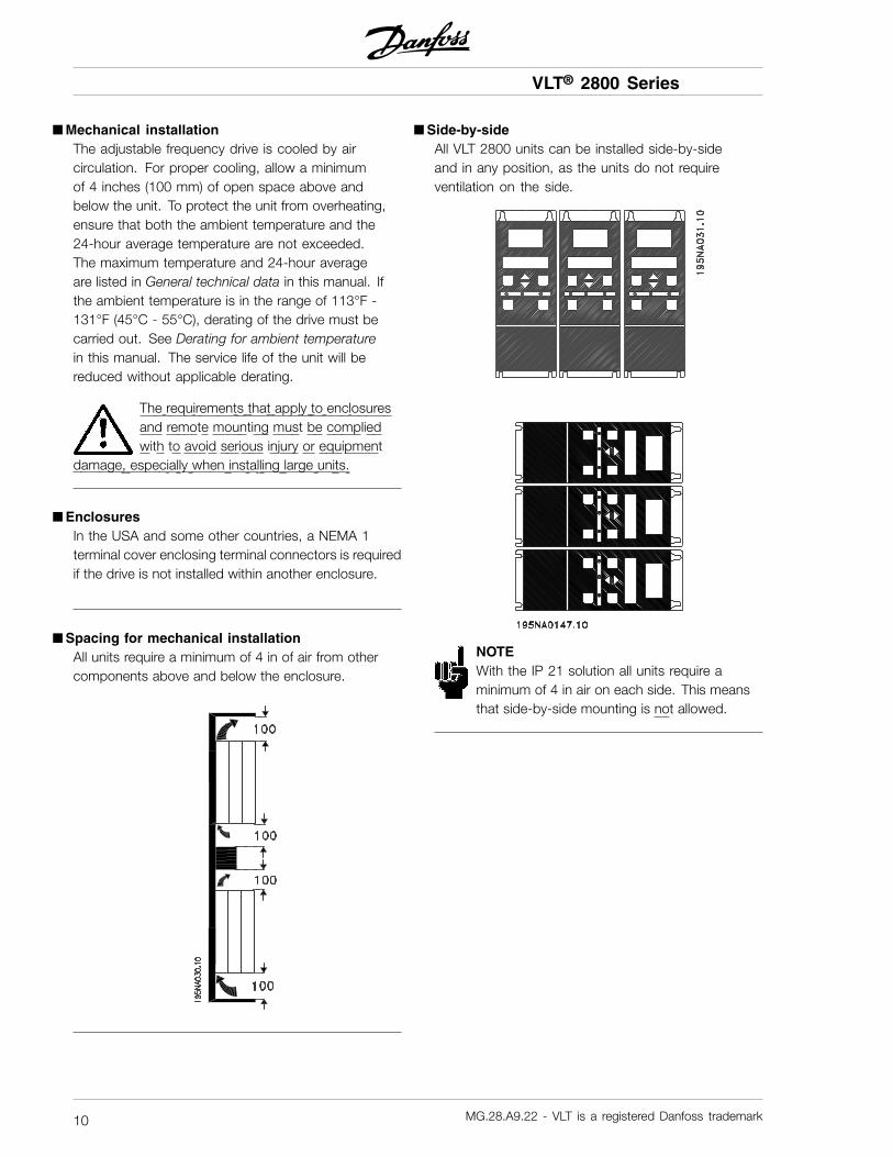
■ Mechanical installationThe adjustable frequency drive is cooled by aircirculation. For proper cooling, allow a minimumof 4 inches (100 mm) of open space above andbelow the unit. To protect the unit from overheating,ensure that both the ambient temperature and the24-hour average temperature are not exceeded.The maximum temperature and 24-hour averageare listed in General technical data in this manual. Ifthe ambient temperature is in the range of 113°F -131°F (45°C - 55°C), derating of the drive must becarried out. See Derating for ambient temperaturein this manual. The service life of the unit will bereduced without applicable derating.
The requirements that apply to enclosuresand remote mounting must be compliedwith to avoid serious injury or equipment
damage, especially when installing large units.
■ EnclosuresIn the USA and some other countries, a NEMA 1terminal cover enclosing terminal connectors is requiredif the drive is not installed within another enclosure.
■ Spacing for mechanical installationAll units require a minimum of 4 in of air from othercomponents above and below the enclosure.
■ Side-by-sideAll VLT 2800 units can be installed side-by-sideand in any position, as the units do not requireventilation on the side.
NOTEWith the IP 21 solution all units require aminimum of 4 in air on each side. This meansthat side-by-side mounting is not allowed.
MG.28.A9.22 - VLT is a registered Danfoss trademark10

VLT® 2800 Series
■ General information about electrical installation
■ High voltage warning
The voltage of the adjustable frequencydrive is dangerous whenever the driveis connected to the AC line. Incorrect
installation of the motor or drive may cause damageto the equipment, serious injury or death. Complywith the safety instructions in this manual as wellas local and national rules and safety regulations.Touching electrical parts may be fatal - even after theequipment has been disconnected from the AC line.Wait at least 4 minutes for current to dissipate.
NOTEIt is the responsibility of the user or installerto ensure correct grounding and protection inaccordance with national and local standards.
■ GroundingComply with the following at installation:
• Safety grounding: The drive has a high leakagecurrent and must be grounded properly for safety.Follow all local safety regulations.
• High frequency grounding: Keep groundingcables as short as possible.
Connect all grounds to ensure the lowest possibleconductor impedance. The lowest possible conductorimpedance is achieved by keeping the conductor asshort as possible and by grounding with the greatestpossible surface area. If multiple drives are installedin a cabinet, the cabinet backplate, which must bemade of metal, should be used as a joint groundreference plate. The drives must be fitted to thebackplate at the lowest possible impedance.
To achieve low impedance, connect the drive to thebackplate with the drive fastening bolts. Removeall paint from the contact points.
■ High voltage testA high voltage test can be performed by short-circuitingterminals U, V, W, L1, L2 and L3, and applyingmax. 2160 V DC in 1 sec. between thisshort-circuit and terminal 95.
MG.28.A9.22 - VLT is a registered Danfoss trademark 11
Inst
alla
tion

VLT® 2800 Series
■ EMC-correct electrical installationGeneral points to be observed to ensureEMC-correct electrical installation.
- Use only shielded/armoured motor cables andshielded/armoured control cables.
- Connect the screen to ground at both ends.- Avoid installation with twisted shield ends (pigtails),
since this ruins the shielding effect at highfrequencies. Use cable clamps instead.
- It is important to ensure good electrical contact fromthe installation plate through the installation screwsto the metal cabinet of the variable frequency drive.
- Use starwashers and galvanically conductiveinstallation plates.
- Do not use unshielded/unarmoured motorcables in the installation cabinets.
The illustration below shows EMC-correct electricalinstallation, in which the variable frequencydrive has been fitted in an installation cabinetand connected to a PLC.
MG.28.A9.22 - VLT is a registered Danfoss trademark12

VLT® 2800 Series
■ Grounding of shielded/armoured control cablesIn general control cables must be shielded/armoured,and the shield must be connected to the unit’s metalcabinet with a cable clamp at each end.
The drawing below shows the correct way to performthe grounding, and what to do when in doubt.
1. Correct groundingControl cables and cables for serialcommunication must be attached with cableclamps at both ends to ensure maximumpossible electrical contact.
2. Incorrect groundingDo not use twisted shield ends that areplaited together (pigtails), as these increase shieldimpedance at higher frequencies.
3. Protection with respect to groundpotential between PLC and VLTf the ground potential between the VLTvariable frequency drive and the PLC (etc.)is different, electric noise may occur that willdisturb the whole system. This problem canbe solved by fitting an equalising cable, to beplaced next to the control cable. Minimum cablecross-section: 6 AWG (16 mm2).
4. n the event of a 50/60 Hz ground loopIf very long control cables are used, 50/60 Hzground loops can arise, and these can interferewith the whole system. This problem is resolvedby attaching one end of the shield to the groundvia a 100 nF capacitor (short pin length).
MG.28.A9.22 - VLT is a registered Danfoss trademark 13
Inst
alla
tion

VLT® 2800 Series
■ Diagram
* Integrated 1A RFI filter and brake is an option.** VLT 2803-2815 200-240 V is not suppliedwith intermediate circuit coils.
MG.28.A9.22 - VLT is a registered Danfoss trademark14

VLT® 2800 Series
Inst
alla
tion
■ Electrical installation
See also the section Brake Connection.
VLT 2803-2815 200-240 V, 2805-2815 380-480 V
VLT 2822 200-240 V, 2822-2840 380-480 V
MG.28.A9.22 - VLT is a registered Danfoss trademark 15
Inst
alla
tion

VLT® 2800 Series
VLT 2840 200-240 V, 2855-2875 380-480 V
VLT 2880-2882 380-480 V
Please note that the units will be suppliedwith two bottom plates; one for metric glandsand one for conduits.
MG.28.A9.22 - VLT is a registered Danfoss trademark16

VLT® 2800 Series
■ Safety clampTo maintain the galvanic isolation (PELV) betweenthe control terminals and high-voltage terminals, theaccompanying safety clamp must be attached toVLT 2803-2815, 200-240 V, and VLT 2805-2815,380-480 V. Attach the safety clamp to the strainrelief plate with the two screws provided.
■ Input fusesFor all unit types, external fuses must be fitted in theAC line supply to the drive. For UL/cUL applicationswith an AC voltage of 200-240 Volts, use fuses typeBussmann KTN-R (200-240 Volts) or Ferraz Shawmuttype ATMR (max. 30A). For UL/ cUL applicationswith an AC voltage of 380-480 Volts, use fuses typeBussmann KTS-R (380-480 Volts). See Technical datain this manual for correct dimensioning of fuses.
It is the responsibility of the installer oruser to insure proper external AC powerinput fusing to the drive.
■ AC line connection
All drives that are equipped with an RFIfilter cannot be connected to a groundedDELTA or IT mains/AC line system.
NOTECheck that the AC voltage matches the voltagerating of the drive. The drive rating is on thedrive nameplate. See Technical data in this
manual for correct dimensioning of cable cross-section.
For single phase 220-240 Volts input, attach theneutral wire to terminal N (L2) and connect thephase wire to terminal L1 (L1).
No. N(L2) L1(L1) (L3) AC line voltage 1 x 220-240 VN L1
No. 95 Ground connection
No. N(L2) L1(L1) (L3) AC line voltage 3 x 220-240 VL2 L1 L3
No. 95 Ground connection
No. 91 92 93 AC line voltage 3 x 380-480 VL1 L2 L3
No. 95 Ground connection
380-460 Volt units with RFI-filters may notbe connected to AC line supplies in whichthe voltage between phase and ground is
more than 300 Volts. Please note that for the AC linefor IT and the delta ground the AC line voltage canexceed 300 Volts between phase and ground. Unitswith type code R5 can be connected to mains supplieswith up to 400 V between phase and ground.
See Technical data for correct dimensioningof cable cross-section.
■ Motor connection
NOTEIt is recommended that an LC filter beconnected to the output of the drive for motorswithout phase insulation paper.
See Technical data in this manual for correctdimensioning for cable cross-section. All typesof three-phase asynchronous standard motorscan be connected to a drive.
Connect the motor to terminals 96, 97, 98.Connect ground to terminal 99.
N0. 96 97 98 Motor voltage 0-100%U V W of AC line voltage.
N0. 99 Ground connection
See Technical data for correct dimensioningof cable cross-section.
Ensure that the motor is wired for the line voltagebefore connecting to the drive.
■ Direction of motor rotationTo change the direction of motor rotation, switch anytwo phases at the drive output or at motor terminals.
■ Motor thermal protectionThe electronic thermal relay in UL approved variablefrequency drives has received the UL approval for singlemotor protection, when parameter 128 Motor thermalprotection has been set for ETR Trip and parameter
MG.28.A9.22 - VLT is a registered Danfoss trademark 17
Inst
alla
tion

VLT® 2800 Series
105 Motor current, IM, N has been programmed tothe rated motor current (see motor nameplate).
■ Parallel connection of motors
The adjustable frequency drive is able to controlseveral motors connected in parallel. The combinedtotal current consumption of the motors is not toexceed the maximum rated output current (IINV) forthe adjustable frequency drive. If the motors are tohave different rpm values, use motors with differentrated rpm values. Motor frequency is changedsimultaneously, which means that the ratio betweenthe rated rpm values is maintained.
Problems may arise at start-up and when operatingat low rpm if the motor sizes are widely different.This is because the small motors’ relatively highresistance in the stator calls for a higher voltageat the start-up and at low rpm.
In systems with motors connected inparallel, the electronic thermal relay (ETR)of the adjustable frequency drive cannot
be used as motor protection for the individual motor.Protection must be provided individually for each motor.
■ Motor cablesSee Technical data for correct sizing of motor cablecross-section and length. Always comply with nationaland local regulations on cable cross-section.
NOTEIf an unshielded/unarmoured cable is used,some EMC requirements are not complied with,see EMC test results in the Design Guide.
If the EMC specifications regarding emission areto be complied with, the motor cable must beshielded/armoured, unless otherwise stated for theRFI filter in question. It is important to keep themotor cable as short as possible so as to reduce thenoise level and leakage currents to a minimum. Themotor cable shield must be connected to the metalcabinet of the variable frequency drive and to the metalcabinet of the motor. The shield connections are tobe made with the biggest possible surface area (cableclamp). This is enabled by different installation devicesin different variable frequency drives. Mounting withtwisted shield ends (pigtails) is to be avoided, sincethese spoil the shielding effect at high frequencies. Ifit is necessary to break the shield to install a motorisolator or motor relay, the shield must be continuedat the lowest possible HF impedance.
■ Brake connection
NOTEVoltages up to 850 VDC occur on the terminals.
No. 81 82 Brake resistorR- R+ terminals
Connect the brake resistor wiring to drive terminals 81and 82. The connection cable to the brake resistormust be shielded/armored. Connect the shield toboth the ground of the drive and the brake resistor bymeans of cable clamps. Dimension the cross-sectionof the brake cable to match the brake torque.
■ Ground connectionSince the leakage currents to ground may be higherthan 3.5 mA, the adjustable frequency drive mustalways be connected to ground in accordance withapplicable national and local regulations. To ensurethat the ground cable has good mechanical connectionto terminal 95, the cable cross section must be aminimum 7 AWG (10 mm2). To improve protection
MG.28.A9.22 - VLT is a registered Danfoss trademark18

VLT® 2800 Series
even further, a Recidual Current Device (RCD) can befitted to ensure that the adjustable frequency drivecuts out when the leakage currents get too high. Alsosee RCD Application note MN.90.GX.02.
■ Load sharingLoad sharing provides the facility to connect severaladjustable frequency drives’ DC intermediate circuits.This requires that the installation is extended using
extra fuses and AC coils (see drawing below).For load sharing, parameter 400 Brake functionmust be set to Load sharing [5].Use 0.25 in (6.3 mm) Faston Plugs for DC(Load Sharing).Contact Danfoss or see instructions no. MI.50.NX.02for further information.
No. 88 89 Load sharing- +
Note that voltage levels of up to 850 V DCmay occur between terminals 88 and 89.
■ Tightening Torque, Power TerminalsPower and ground terminals must be tightenedwith the following torques:
VLT Terminals Torque [Nm]Power AC line brake 0.5-0.62803-
2875 Ground 2-3Power AC line brake 1.2-1.52880-
2882 Ground 2-3
■ Calculation of brake resistanceIn lifting/lowering applications you need to be ableto control an electromagnetic brake. The brake iscontrolled using a relay output or digital output (terminal46). The output must be kept closed (voltage-free)for the period of time during which the variablefrequency drive is not able to ’support’ the motor,for example due to the load being too great. SelectMechanical brake control in parameter 323 or 341 forapplications with an electromagnetic brake.When the output frequency exceeds the brake cutout value set in par. 138, the brake is released if themotor current exceeds the preset value in parameter
140. When stopping the brake is engaged when theoutput frequency is less than the brake engagingfrequency, which is set in par. 139.If the variable frequency drive is placed at alarmstatus or in an overvoltage situation the mechanicalbrake is cut in immediately.
NOTEThis application is only for lifting/loweringwithout a counterbalance.
■ Access to control terminalsAll control terminals are located underneath theprotective plate on the front of the adjustablefrequency drive. Remove the protective plate bysliding it downwards (see drawing).
MG.28.A9.22 - VLT is a registered Danfoss trademark 19
Inst
alla
tion

VLT® 2800 Series
■ Electrical installation, control circuitry
NOTEUsing unshielded/unarmored cable may notcomply with some EMI/RFI requirements.
Control wires must be shielded/armored. Connect theshield to the drive chassis with a clamp. Normally,the shield must also be connected to the chassis ofthe controlling device. (See the instructions for thespecific device.) In analog signals or connections usingvery long wires, 50/60 Hz ground loops may occurbecause of noise transmitted from the AC line. It maybe necessary to break the shield and insert a 100 µFcapacitor between the shield and the chassis.
MG.28.A9.22 - VLT is a registered Danfoss trademark20

VLT® 2800 Series
■ Tightening torques, control cablesControl wires must be connected with a tighteningtorque of 0.22–0.25 Nm.
■ Electrical installation, control terminals
NOTEUsing unshielded/unarmored cable may notcomply with some EMC/RFI requirements.
Refer to the following table for VLT 2800 terminaldesignations and their functional descriptions.
No. Function01-03 Relay outputs 01-03 can be used for
indicating status and alarms/warnings.12 24 VDC voltage supply.18-33 Digital inputs.20, 55 Common frame for input
and output terminals.42 Analog output for displaying frequency,
reference, current or torque.461 Digital output for displaying status,
warnings or alarms, as well asfrequency output.
50 +10 VDC supplyvoltage for potentiometer or thermistor.
53 Analog voltage input 0 - 10 V DC.60 Analog current input 0/4 - 20 mA.671 + 5 VDC supply voltage
to Profibus.68,691
RS-485, Serial communication.
701 Frame for terminals 67, 68 and 69.Normally this terminal is not to be used.
1. The terminals are not valid for DeviceNet. See theDeviceNet manual, MG.90.BX.YY for further details.
NOTETo supply internal 24 VDC voltage to thedigital input terminals, jumper terminal12 to terminal 27.
■ Relay connectionSee parameter 323, Relay output for programmingof relay output.
No. 01 - 02 1 - 2 make (normally open)01 - 03 1 - 3 break (normally closed)
NOTEThe cable jacket for the relay must coverthe first row of control card terminals -otherwise the galvanic isolation (PELV)
cannot be maintained. Maximum cable diameter:0-160 in (4 mm). See drawing.
■ Profibus DIP switches setting
The dip switch is only on the control card with ProfibusDP communication. The switch position shown is thefactory setting. Switches 1 and 2 are used as cabletermination for the RS-485 interface. If the adjustablefrequency drive is located as the first or last (or only)unit in the bus system, switches 1 and 2 must be ON.On the remaining adjustable frequency drives, switches1 and 2 must be OFF. Switches 3 and 4 are not applied.
MG.28.A9.22 - VLT is a registered Danfoss trademark 21
Inst
alla
tion

VLT® 2800 Series
■ VLT Software DialogConnection to terminals 68-70 orSub D:- PIN 3 GND- PIN 8 P-RS 485- PIN 9 N-RS 485
■ Sub D plug
An LCP 2 control unit can be connected to the Sub Dplug on the control card. Ordering number: 175N0131.LCP control units with ordering number 175Z0401are not to be connected.
MG.28.A9.22 - VLT is a registered Danfoss trademark22

VLT® 2800 Series
■ Connection examples
■ Start/stopStart/stop using terminal 18 and coastingstop using terminal 27.
Par. 302 Digital input = Start [7]Par. 304 Digital input = Coasting stop inverted [2]
For Precise start/stop the following settings are made:Par. 302 Digital input = Precise start/stop [27]Par. 304 Digital input = Coasting stop inverted [2]
■ Pulse start/stopPulse start using terminal 18 and pulse stopusing terminal 19. In addition, the jog frequencyis activated via terminal 29.
Par. 302 Digital input = Pulse start [8]Par. 303 Digital input = Stop inverted [6]Par. 304 Digital input = Coasting stop inverted [2]Par. 305 Digital input = Jog [13]
■ Speed up/slow downSpeed up/slow down using terminals 29/33.
Par. 302 Digital input = Start [7]Par. 303 Digital input = Freeze reference [14]Par. 305 Digital input = Speed up [16]Par. 307 Digital input = Slow down [17]
■ Potentiometer referenceVoltage reference via a potentiometer.
Par. 308 Analog input = Reference [1]Par. 309 Terminal 53, min. scaling = 0 VoltPar. 310 Terminal 53, max. scaling = 10 Volt
■ Connection of a 2-wire transmitterConnection of a 2-wire transmitter as feedbackto terminal 60.
MG.28.A9.22 - VLT is a registered Danfoss trademark 23
Inst
alla
tion

VLT® 2800 Series
Par. 314 Analog input = Feedback [2]Par. 315 Terminal 60, min. scaling = 4 mAPar. 316 Terminal 60, max. scaling = 20 mA
MG.28.A9.22 - VLT is a registered Danfoss trademark24

VLT® 2800 Series
■ Control unitOn the front of the variable frequency drivethere is a control panel.
The control panel is divided into five functional groups:1. Status LED2. Keys for changing parameters and shifting
display function.3. LEDs.4. Keys for local operation.
All displays of data are in the form of a six-digit LEDdisplay capable of showing one item of operatingdata continuously during normal operation. As asupplement to the display, there are three LEDsfor indication of electrical connection (ON), warning(WARNING) and alarm (ALARM). Most of thevariable frequency drive’s parameter Setups can bechanged immediately via the control panel, unlessthis function has been programmed as Locked [1]via parameter 018 Lock for data changes.
■ Control keys[QUICK MENU] allows access to the parametersused for the Quick menu.The[QUICK MENU] key is also used if a change to aparameter value is not to be implemented.See also [QUICK MENU] + [+].
[CHANGE DATA] is used for changing a setting.
The [CHANGE DATA] key is also used for confirminga change of parameter settings.
[+] / [-] are used for selecting parameters andfor changing parameter values.These keys are also used in Display mode for selectingthe display of an operating value.
The [QUICK MENU] + [+] keys must bepressed at the same time to give access to allparameters. See Menu mode.
[STOP/RESET] is used for stopping theconnected motor or for resetting the variablefrequency drive after a trip.Can be selected as Active [1] or Not active [0] viaparameter 014 Local stop/reset. In Display mode, thedisplay will flash if the stop function is activated.
NOTEIf the [STOP/RESET] key is set at Not active[0] in parameter 014 Local stop/reset,andthere is no stop command via the digital
inputs or serial communication, the motor canonly be stopped by disconnecting the electricalvoltage to the variable frequency drive.
[START] is used for starting the variable frequencydrive. It is always active, but the [START] keycannot override a stop command.
■ Manual initializationTo manually initialize the adjustable frequency drive tofactory default settings, first disconnect AC line voltage.Hold the [QUICK MENU] and [+] and [CHANGE DATA]keys down while simultaneously reconnecting the ACline voltage. Release the keys. The drive has nowbeen programmed for factory settings.
MG.28.A9.22 - VLT is a registered Danfoss trademark 25
Inst
alla
tion

VLT® 2800 Series
■ Display readout statesDisplay mode
In normal operation, one item of operating data canbe displayed continuously at the operator’s ownchoice. By means of the [+/-] keys, the followingoptions can be selected in Display mode:- Output frequency [Hz]- Output current [A]- Output voltage [V]- Intermediate circuit voltage [V]- Output power [kW]- Scaled output frequency fout x p008
Menu mode
In order to enter the Menu mode [QUICK MENU] +[+] must be activated at the same time.In Menu mode, most of the adjustable frequencydrive parameters can be changed. Scroll through theparameters using the [+/-] keys. While scrolling in theMenu mode proceeds, the parameter number will flash.
The display shows that the setting in parameter102 Motor power PM,N is 0.75. In order to changethe value of 0.75, [CHANGE DATA] must firstbe activated; the parameter value can then bechanged using the [+/-] keys.
If for a given parameter the display shows threedots at the right, it means that the parametervalue has more than three digits. In order to seethe value, activate [CHANGE DATA].
The display shows that in parameter 128 Motor thermalprotection the selection made is Thermistor trip [2].
Quick menu
Using the [QUICK MENU] key, it is possible to accessthe 12 most important parameters of the adjustablefrequency drive. After programming, the adjustablefrequency drive is in most cases ready for operation.When the [QUICK MENU] key is activated in Displaymode, the Quick menu starts. Scroll through the quickmenu using the [+/-] keys and change the data valuesby first pressing [CHANGE DATA] and then changingthe parameter value with the [+/-] keys.The Quick menu parameters are:• Par. 100 Configuration• Par. 101 Torque characteristic• Par. 102 Motor power PM,N
• Par. 103 Motor voltage UM,N
• Par. 104 Motor frequency fM,N
• Par. 105 Motor current IM,N
• Par. 106 Rated motor speed nM,N
• Par. 107 Automatic motor adaptation• Par. 202 Output frequency high limit fMAX
• Par. 203 Reference range• Par. 204 Minimum reference RefMIN
• Par. 205 Maximum reference RefMAX
• Par. 207 Ramp-up time• Par. 208 Ramp-down time• Par. 002 Local/remote operation• Par. 003 Local reference
Parameter 102 - 106 can be read out fromthe motor’s nameplate.
Automatic motor tuningAutomatic motor tuning (AMT) is performed as follows:
1. In parameter 107 Automatic motor tuning,select data value [2]. "107" will now flash,and "2" will not flash.
MG.28.A9.22 - VLT is a registered Danfoss trademark26

VLT® 2800 Series
2. AMT is activated by pressing start. "107" willnow flash and dashes will move from left toright in the data value field.
3. When "107" appears once more with the datavalue [0], AMT is complete. Press [STOP/RESET]to save the motor data.
4. "107" will then continue to flash with the datavalue [0]. You can now proceed.
NOTEVLT 2880-2882 do not have AMT function.
MG.28.A9.22 - VLT is a registered Danfoss trademark 27
Inst
alla
tion
VLT® 2800 Series
■ Display readoutFrThe variable frequency drive shows the presentoutput frequency in Hertz [Hz].
IoThe variable frequency drive shows the presentoutput current in Amps [A].
UoThe variable frequency drive shows the presentoutput voltage in Volt [V].
UdThe variable frequency drive shows the intermediatecircuit voltage in Volt [V].
PoThe variable frequency drive shows the calculatedoutput in kilowatt [kW].
notrunThis message is shown if an attempt is made to changea parameter value while the motor is running. Stopthe motor to change the parameter value.
LCPThis message is shown if an LCP 2 control unit isfitted and the [QUICK MENU] or [CHANGE DATA]key is activated. If an LCP 2 control unit is fittedyou can only change parameters with that.
HaThe variable frequency drive shows the present Handmode reference frequency in Herz (Hz).
SCThe variable frequency drive shows scaledoutput frequency (the present output frequencyx parameter 008).
■ Hand / Auto mode operationDuring Auto mode operation, the adjustable frequencydrive receives an external reference through the controlterminals as analog or digital signals. In Auto mode, usethe [+] and [-] keys to scroll through the display of drivestatus messages. In Hand mode, it is possible to controlthe speed of the drive locally through the keypad.
On the control terminals, the following control signalswill remain active when Hand mode is activated:• Hand Start (LCP2)• Off Stop (LCP2)• Auto Start (LCP2)• Reset• Coasting Stop Inverse• Reset and Coasting Stop Inverse• Quick Stop Inverse• Stop Inverse• Reversing• DC Braking Inverse• Setup Select LSB• Setup Select MSB• Thermistor• Precise Stop Inverse• Precise Stop/Start• Jog• Stop Command Via Serial Comm.
Switching between Auto and Hand mode:To switch between operational modes, pressthe [Change Data] key. The display will indicatethe current mode of operation.
Use the [+] and [-] keys to toggle between Handand Auto mode. Press the [Change Data] keyagain to activate the selected mode, otherwisethe mode displayed will take effect automaticallyin about three seconds.
Operation in Hand mode:When the adjustable frequency drive is running normallyin Hand mode, the display will show HA to indicateHand mode along with the drive output frequency.
MG.28.A9.22 - VLT is a registered Danfoss trademark28

VLT® 2800 Series
In Hand mode, the local speed reference can beincreased or decreased with the [+] and [-] keys:
In Hand mode, the [+] and [-] keys are also used totoggle through status messages. Press and hold the[Change Data] key for approximately 3 seconds. Whenthe display begins to flash, use the [+] and [-] keysto change the drive status display. The displays aretemporary and will default back to output frequency.
NOTEParameter 020 can be used to disableHand mode operation.
■ Warnings/alarmsWarnings or alarms appear in the LED display as anumerical code [Err. xx]. A warning is displayed untilthe fault has been corrected, while an alarm will flashuntil the [STOP/RESET] key is pressed. The table inWarnings/alarms messages in this manual explainsthe various warnings and alarms, and whether a faultlocks the adjustable frequency drive. After a Triplocked fault, cut off the AC line supply and correct thefault. Then reconnect the AC line supply and pressthe [STOP/RESET] key. The adjustable frequencydrive is now reset and ready. See Warnings/alarmsmessages in this manual for more detail.
MG.28.A9.22 - VLT is a registered Danfoss trademark 29
Inst
alla
tion

VLT® 2800 Series
■ Special conditions
■ Derating for ambient temperatureThe ambient temperature (TAMB,MAX) is the maximumtemperature allowed. The average (TAMB,AVG)measured over 24 hours must be at least 9°F (5 °C)lower. If the adjustable frequency drive operates attemperatures above 113 °F (45 °C), a derating ofthe rated output current is necessary.
■ Temperature-related switching frequencyThis function ensures the highest possible switchingfrequency without the adjustable frequency drivebecoming thermally overloaded. The internaltemperature determines the switching frequency basedon the load, the ambient temperature, the supplyvoltage and the cable length. The function ensures thatthe drive automatically adjusts the switching frequencybetween the minimum and maximum switchingfrequency (parameter 411), see drawing below.
When using the LC filter the minimum switchfrequency is 4.5 kHz.
■ Derating for long motor cablesThe adjustable frequency drive has been designedfor a 240 ft (75 m) unscreened/unarmored cableor a 80 ft (25 m) screened/armored cable anda motor cable with a rated cross-section. If acable with a larger cross-section is required, it isrecommended to reduce the output current by5% for each step that the cable cross-section isincreased. (Increased cable cross-section leadsto increased capacitance to ground, and thus toan increased ground leakage current.)
■ VLT 2800 start-upPre-installation checks1. Compare drive model number to what was ordered.2. Ensure each of following are rated for same voltage:
• Drive• Power line• Motor
3. Record following motor data:• Voltage• Frequency• Full load current• Full load speed• Power - convert HP to kW (See conversion tablein parameter 102, Motor Power, in this manual.)
4. Ensure that rated drive current is equal to orgreater than total full load current.• Drive can be at most one size smaller than motor.• For multiple motor operations, add full loadcurrent ratings of all motors.• If drive rating is less than motor(s), full motoroutput cannot be achieved.
5. Check motor wiring:• Any disconnect between drive and motorshould be interlocked to drive safety interlockcircuit to avoid unwanted drive trips.• No power factor correction capacitors can beconnected between drive and motor.• Two speed motors must be wiredpermanently for full speed.• Y-start, -run motors must be wiredpermanently for run.
MG.28.A9.22 - VLT is a registered Danfoss trademark30

VLT® 2800 Series
Installation checks1. Input fusing in power supply for all drives
must be provided.2. Environmental concerns - for standard
NEMA 1 drive:• Clean air supply• Dry air (5% to 85% relative humidity,non-condensing)• 32°F (0°C) to 104°F (40°C) ambient temperatureoperating range, or as rated• 1000m (3,300 ft) maximum elevationwith no derating• Keep any construction dirt out of drive.
3. Wiring• Wire drive in accordance with instructionsand diagrams received with drive.• Separate conduits must be provided to drive forinput power, output power, and control wiring.• Protect signal wires from noise.• Ground each drive individually.• Double check input and output powerwiring for correct location.
Setting up drive for motor startEnsure that all warnings provided in this manual havebeen adhered to. Apply power to the unit. Enter motornameplate data into drive through Quick Menu.1. Parameter 102, MOTOR POWER (in kW) (See
conversion table in parameter 102, MotorPower, in this manual.)
2. Parameter 103, MOTOR VOLTAGE3. Parameter 104, MOTOR FREQUENCY4. Parameter 105, MOTOR CURRENT5. Parameter 106, MOTOR SPEED6. Parameter 107, select AUTOMATIC
MOTOR TUNING
Operational tests - HAND1. Check motor rotation from drive. If incorrect,
disconnect input power from drive and reversetwo leads between drive and motor.
2. Accelerate motor quickly to full speedand verify operation.
3. Decelerate motor quickly to stop andverify operation.
4. Operate motor over entire speed range whileclosely checking for resonance.
Operational tests - AUTO1. Ensure that drive follows run/stop and safety
interlock commands from system.2. Ensure drive follows speed reference, or
feedback, from system.
MG.28.A9.22 - VLT is a registered Danfoss trademark 31
Inst
alla
tion

VLT® 2800 Series
■ Operation & Display
001 Language
(LANGUAGE)
Value:✭English (ENGLISH) [0]
German (DEUTSCH) [1]French (FRANCAIS) [2]Danish (DANSK) [3]Spanish (ESPANOL) [4]Italian (ITALIANO) [5]
Function:This parameter is used to choose the languageto be shown in the display whenever the LCPcontrol unit is connected.
Description of choice:
There is a choice of the languages shown. Thefactory setting may vary.
002 Local/remote operation
(OPERATION SITE)
Value:✭Remote operation (REMOTE) [0]
Local operation (LOCAL) [1]
Function:There is a choice of two different modes of operationof the variable frequency drive. Remote operation [0]or Local operation [1]. See also parameter 013 Localcontrol if Local operation [1] is selected.
Description of choice:
If Remote operation [0] is selected, the variablefrequency drive is controlled via:1. the control terminals or via serial communication.2. the [START] key. This cannot, however, override
stop commands transmitted via the digital inputsor via serial communication.
3. the [STOP/RESET] and [JOG] keys, on thecondition that these are active.
If Local operation [1], is selected, the variablefrequency drive is controlled via:1. the [START] key. This cannot, however, override
stop commands via the digital inputs (seeparameter 013 Local control).
2. the [STOP/RESET] and [JOG] keys, on thecondition that these are active.
3. the [FWD/REV] key, on the condition that is hasbeen selected as active in parameter 016 Localreversing, and that parameter 013 Local controlis set at Local control and open loop [1] or Localcontrol as parameter 100 [3]. Parameter 200Output frequency range is set at Both directions.
4. parameter 003 Local reference where the referencecan be set using the [+] and [-] keys.
5. an external control command that can beconnected to the digital inputs (see parameter013 Local control).
NOTEThe [JOG] and [FWD/REV] keys are locatedon the LCP control unit.
003 Local reference(LOCAL REFERENCE)
Value:Par. 013 Local control must be set to [1] or [2]:0 - fMAX (par. 202) ✭ 50 Hz
Par. 013 Local control must be set to [3] or [4].RefMIN - Ref MAX (par. 204-205) ✭ 0,0
Function:In this parameter, the local reference can be setmanually. The unit of the local reference depends on theconfiguration selected in parameter 100 Configuration.
Description of choice:
In order to protect the local reference, parameter002 Local/remote operation must be set toLocal operation [1]. Local reference cannot beset via serial communication.
004 Active Setup
(ACTIVE SETUP)
Value:Factory Setup (FACTORY SETUP) [0]
✭setup 1 (SETUP 1) [1]
✭ = factory setting. () = display text [] = value for use in communication via serial communication port
MG.28.A9.22 - VLT is a registered Danfoss trademark32

VLT® 2800 Series
Pro
gram
min
g
setup 2 (SETUP 2) [2]Setup 3 (SETUP 3) [3]setup 4 (SETUP 4) [4]Multi Setup (MULTI SETUP) [5]
Function:The active parameter Setup is selected here. Allparameters can be programmed in four individualparameter Setups. Shifts between Setups canbe made in this parameter via a digital inputor via serial communication.
Description of choice:
Factory Setup [0] contains the factory-set parametervalues. Setup 1-4 [1]-[4] are four individualSetups which can be selected as required. MultiSetup [5] is used where remote-controlled shiftsbetween the four Setups via a digital input or viaserial communication is required.
005 Programming Setup
(EDIT SETUP)
Value:Factory Setup (FACTORY SETUP) [0]Setup 1 (SETUP 1) [1]Setup 2 (SETUP 2) [2]Setup 3 (SETUP 3) [3]Setup 4 (SETUP 4) [4]
✭Active Setup (ACTIVE SETUP) [5]
Function:You can select which Setup you want to programduring operation (applies both via the control paneland the serial communication port). It is, for example,possible to program Setup 2 [2], while the active Setupis set to Setup 1 [1] in parameter 004 Active Setup .
Description of choice:
Factory Setup [0] contains the factory-set data and canbe used as a source of data if the other Setups are to bereset to a known status. Setup 1-4 [1]-[4] are individualSetups that can be programmed freely during operation.If Active Setup [5] is selected, the programming Setupwill be equal to parameter 004 Active Setup.
NOTEIf data is modified or copied to the activeSetup, the modifications have an immediateeffect on the unit’s operation.
006 Setup copying
(SETUP COPY)
Value:✭No copying (NO COPY) [0]
Copy to Setup 1 from #(COPY TO SETUP 1) [1]Copy to Setup 2 from #(COPY TO SETUP 2) [2]Copy to Setup 3 from #(COPY TO SETUP 3) [3]Copy to Setup 4 from #(COPY TO SETUP 4) [4]Copy to all Setups from # (COPY TO ALL) [5]
Function:You can copy from the selected active Setup inparameter 005 Programming setup to the selectedSetup or Setups in this parameter.
NOTECopying is only possible in Stop (motor stoppedin connection with a stop command).
Description of choice:
Copying begins when the required copying functionhas been selected and the [OK]/[CHANGE DATA]key has been pushed. The display indicateswhen copying is in progress.
007 LCP copy
(LCP COPY)
Value:✭No copying (NO COPY) [0]
Upload all parameters (UPL. ALL PAR.) [1]Download all parameters (DWNL. ALL PAR.) [2]Download size-independent parameters(DWNL.OUTPIND.PAR.) [3]
Function:Parameter 007 LCP copy is used if you want to usethe LCP 2 control panel’s integral copy function. Thefunction is used if you want to copy all parametersetups from one variable frequency drive to anotherby moving the LCP 2 control panel.
Description of choice:
Select Upload all parameters [1] if you want allparameter values to be transferred to the control panel.Select Download all parameters [2] if all parameter
✭ = factory setting. () = display text [] = value for use in communication via serial communication port
MG.28.A9.22 - VLT is a registered Danfoss trademark 33

VLT® 2800 Series
values transferred are to be copied to the frequencyconverter to which the control panel is attached. SelectDownload size-independent par. [3] if you only wantto downloade the size-independent parameters. Thisis used when downloading to a variable frequencydrive with a different rated power size than that fromwhich the parameter setup originates.
NOTEUpload/download can only be performedin stop mode. Download can only beperformed to a frequency converter with
the same software version number, see parameter626 Database identification no.
008 Display scaling of output frequency
(FREQUENCY SCALE)
Value:0.01 - 100.00 ✭ 1.00
Function:In this parameter, the factor is selected by which theoutput frequency is to be multiplied. The value is shownin the display, provided parameters 009-012 Displayreadout have been set to Output frequency x scaling [5].
Description of choice:
Set the required scaling factor.
009 Large display readout
(DISPLAY LINE 2)
Value:No readout (NONE) [0]Resulting reference [%](REFERENCE %) [1]Resulting reference [unit](REFERENCE [UNIT]) [2]Feedback [unit] (FEEDBACK [UNIT]) [3]
✭Frequency [Hz] (FREQUENCY [HZ]) [4]Output frequency x scaling(FREQUENCY X SCALE) [5]Motor current [A] (MOTOR CURRENT [A]) [6]Torque [%] (TORQUE [%]) [7]Power[kW] (POWER[KW]) [8]Power [HP] (POWER [HP][US]) [9]Motor voltage [V](MOTOR VOLTAGE [V]) [11]DC link voltage [V]
(DC LINK VOLTAGE [V]) [12]Thermal load motor [%](MOTOR THERMAL [%]) [13]Thermal load [%](FC. THERMAL[%]) [14]Running hours [Hours](RUNNING HOURS]) [15]Digital input [Bin](DIGITAL INPUT[BIN]) [16]analog input 53 [V](ANALOG INPUT 53 [V]) [17]Analog input 60 [mA](ANALOG INPUT 60 [MA]) [19]Pulse reference [Hz](PULSE REF. [HZ]) [20]External reference [%](EXTERNAL REF. [%]) [21]Status word [Hex] (STATUS WORD [HEX]) [22]Heatsink temperature [°C](HEATSINK TEMP [°C]) [25]Alarm word [Hex] (ALARM WORD [HEX]) [26]Control word [Hex] (CONTROL WORD [HEX]) [27]Warning word [Hex](WARNING WORD [HEX]) [28]Extended status word [Hex](EXT. STATUS [HEX]) [29]Communication option card warning(COMM OPT WARN [HEX]) [30]Pulse count(PULSE COUNTER) [31]
Function:In this parameter you can select the data value thatyou wish to display in the LCP control unit displayline 2 when the variable frequency drive is switchedon. The display will also be included in the scrollbarin display mode. In parameters 010-012 Displayreadout you can select a further three data values,which are displayed in display line 1.
Description of choice:
No readout can only be selected in parameters010-012 Small display readout.
Resulting reference [%] gives, as a percentage,the resulting reference in the range from Minimumreference, RefMIN to Maximum reference, RefMAX.
Reference [unit] gives the resulting reference with unitHz in Open loop. In Closed loop the reference unitis selected in parameter 416 Process units.
✭ = factory setting. () = display text [] = value for use in communication via serial communication port
MG.28.A9.22 - VLT is a registered Danfoss trademark34

VLT® 2800 Series
Feedback [unit] gives the resulting signal valueusing the unit/scaling selected in parameter 414Minimum feedback, FBLOW, 415 Maximum feedback,FBHIGH and 416 Process units.
Frequency [Hz] gives the output frequency ofthe variable frequency drive.
Output frequency x scaling [-] equals the present outputfrequency fM multiplied by the factor set in parameter008 Display scaling of output frequency .
Motor current [A] gives the phase current of themotor measured as an effective value.
Torque [%] denotes the motor’s present load inrelation to the motor’s rated torque.
Power [kW] gives the present power that themotor is absorbing in kW.
Power [HP] gives the present power that themotor is absorbing in HP.
Motor voltage[V] gives the voltage supplied to the motor.
DC link voltage [V] gives the intermediate circuitvoltage of the variable frequency drive.
Thermal load motor [%] gives the calculated/estimatedload on the motor. 100% is the cut-out limit.
Thermal load [%] gives the calculated/estimatedthermal load on the variable frequency drive.100% is the cut-out limit.
Running hours [Hours] gives the number of hours thatthe motor has tun since the last reset in parameter619 Reset of running hours counter.
Digital input [Binary code] gives the signal statusfrom the 5 digital inputs (18, 19, 27, 29 and 33).Terminal 18 corresponds to the bit on the extremeleft. ‘0’ = no signal, ‘1’ = signal connected.
Analog input 53 [V] gives the voltage value of terminal 53.
Analog input 60 [mA] gives the present valueof terminal 60.
Pulse reference [Hz] gives the reference in Hzconnected to terminal 33.
External reference [%] gives the sum of externalreferences as a percentage (sum of analog/pulse/serial
communication) in the range from Minimum reference,RefMIN to Maximum reference, RefMAX.
Status word [Hex] gives one or several statusconditions in a Hex code. See Serial communicationin the Design Guide for further information.
Heatsink temp.[°C] gives the present heatsinktemperature of the variable frequency drive. Thecut-out limit is 195-212 °F (90-100°C), while cuttingback in occurs at 160 ± 5% (70 ± 5°C).
Alarm word [Hex] gives one or several alarmsin hex code. See Serial communication in theDesign Guide for further information.
Control word [Hex] gives the control word for thevariable frequency drive. See Serial communicationin the Design Guide for further information.
Warning word [Hex] gives one or several warningsin hex code. See Serial communication in theDesign Guide for further information.
Extended status word [Hex] gives one or several statusmodes in Hex code. See Serial communication inthe Design Guide for further information.
Communication option card warning [Hex] gives awarning word if there is a fault in the communicationbus. Only active if communication options are installed.If there are no communication options 0Hex is displayed.
Pulse count gives the number of pulses thatthe unit has registered.
010 Small display line 1.1
(DISPLAY LINE 1.1)
Value:See par. 009 Large display readout
✭ Analog input 53 [V] [17]
Function:In this parameter, the first of three data valuescan be selected that is to be displayed in the LCPcontrol unit display, line 1, position 1. This is a usefulfunction, e.g. when setting the PID regulator, asit gives a view of process reactions to referencechanges. The display readout is activated bypushing the [DISPLAY STATUS] key.
✭ = factory setting. () = display text [] = value for use in communication via serial communication port
MG.28.A9.22 - VLT is a registered Danfoss trademark 35
Pro
gram
min
g

VLT® 2800 Series
Description of choice:
See parameter 009 Large display readout.
011 Small display readout 1.2
(DISPLAY LINE 1.2)
Value:See parameter 009 Large display readout
✭ Motor current [A][6]
Function:See the functional description given under parameter010 Small display readout.
Description of choice:
See parameter 009 Large display readout.
012 Small display readout 1.3
(DISPLAY LINE 1.3)
Value:See parameter 009 Large display readout
✭ Feedback [unit] [3]
Function:See the functional description given under parameter010 Small display readout.
Description of choice:
See parameter 009 Large display readout.
013 Local control(LOC CTRL/CONFIG.)
Value:Local not active (DISABLE) [0]Local control and open-loop without slip
compensation(LOC CTRL/OPEN LOOP) [1]Remote-operated control and open-loop
without slip compensation(LOC+DIG CTRL) [2]Local control as parameter 100(LOC CTRL/AS P100) [3]
✭Remote-operated control as parameter 100(LOC+DIG CTRL/AS P100) [4]
Function:This is where the required function is selected if,in parameter 002 Local/remote operation, Localoperation [1] has been chosen.
Description of choice:
If Local not active [0] is selected, it is not possible toset a reference via parameter 003 Local reference.In order to enable a shift to Local not active [0],parameter 002 Local/remote operation must beset to Remote operation [0].
Local control and open loop [1] is used if the motorspeed is to be set via parameter 003 Local reference.When this choice is made, parameter 100 Configurationautomatically shifts to Speed regulation, open loop [0].
Remote-operated control and open loop [2] functionsin the same way as Local control and open loop[1]; however, the adjustable frequency drive canalso be controlled via the digital inputs.
Local control as parameter 100 [3] is used when themotor speed is to be set via parameter 003 Localreference, but without parameter 100 Configurationautomatically shifting to Speed regulation, open loop [0].
Remote-operated control as parameter 100 [4] worksthe same way as Local control as parameter 100[3]; however, the adjustable frequency drive canalso be controlled via the digital inputs.
Shifting from Remote operation to Local operationin parameter 002 Local/remote operation, while thisparameter has been set to Remote-operated controland open loop [1]: The present motor frequency anddirection of rotation will be maintained. If the presentdirection of rotation does not respond to the reversingsignal (negative reference), the reference will be set to 0.
Shifting from Local operation to Remote operationin parameter 002 Local/remote control, whilethis parameter has been set to Remote-operatedcontrol and open loop [1]: The configurationselected in parameter 100 Configuration will beactive. The shift will be smooth.
Shifting from Remote control to Local control inparameter 002 Local/remote operation, while thisparameter has been set to Remote-operated controlas parameter 100 [4]: the present reference willbe maintained. If the reference signal is negative,the local reference will be set to 0.
✭ = factory setting. () = display text [] = value for use in communication via serial communication port
MG.28.A9.22 - VLT is a registered Danfoss trademark36

VLT® 2800 Series
Shifting from Local operation to Remote operationin parameter 002 Local/remote operation, whilethis parameter has been set to Remote operation:The local reference will be replaced by theremote-operated reference signal.
014 Local stop
(LOCAL STOP)
Value:Not active (DISABLE) [0]
✭Active (ENABLE) [1]
Function:In this parameter, the local [STOP]-key can beengaged or disengaged on the control paneland on the LCP control panel.
Description of choice:
If Not active [0] is selected in this parameter,the [STOP]-key will be inactive.
NOTEIf Not active [0] is selected, the motor cannotbe stopped by means of the [STOP]-key.
015 Local jog
(LOCAL JOGGING)
Value:✭Not active (DISABLE) [0]
Active (ENABLE) [1]
Function:In this parameter, the jog function on the LCP controlpanel can be engaged/disengaged.
Description of choice:
If Not active [0] is selected in this parameter,the [JOG]-key will be inactive.
016 Local reverse(LOCAL REVERSE)
Value:✭Not active (DISABLE) [0]
Active (ENABLE) [1]
Function:In this parameter you can select/deselect the reversefunction on the LCP control panel. The key can onlybe used if parameter 002 Local/remote operationis set to Local operation [1] and parameter 013Localcontrol to Local control, open loop [1] orLocal control as parameter 100 [3].
Description of choice:
If Disable [0] is selected in this parameter, the[FWD/REV] key will be disabled. See also parameter200 Output frequency range.
017 Local reset of trip
(LOCAL RESET)
Value:Not active (DISABLE) [0]
✭Active (ENABLE) [1]
Function:In this parameter, the reset function on the controlpanel can be engaged/disengaged.
Description of choice:
If Not active [0] is selected in this parameter, thereset function will be inactive.
NOTESelect Not active [0], only if an external resetsignal has been connected via the digital inputs.
018 Lock for data changes
(DATA CHANGE LOCK)
Value:✭Not locked (NOT LOCKED) [0]
Locked (LOCKED) [1]
Function:In this parameter, it is possible to ’lock’ the controlsto disable data changes via the control keys.
Description of choice:
If Locked [1] is selected, data changes in theparameters cannot be made; however, it willstill be possible to make data changes via serialcommunication. Parameter 009-012 Display readoutcan be changed via the control panel.
✭ = factory setting. () = display text [] = value for use in communication via serial communication port
MG.28.A9.22 - VLT is a registered Danfoss trademark 37
Pro
gram
min
g

VLT® 2800 Series
019 Operating mode at power-up, localoperation
(POWER UP ACTION)
Value:Auto restart, use saved reference(AUTO RESTART) [0]
✭Forced stop, use saved reference(LOCAL=STOP) [1]Forced stop, set ref. to 0(LOCAL=STOP, REF=0) [2]
Function:Setting of the required operating mode when theelectrical voltage is engaged This function can onlybe active if Local operation [1] has been selected inparameter 002 Local/remote operation.
Description of choice:
Auto restart, use saved ref. [0] is selected if the variablefrequency drive is to start using the local reference (setin parameter 003 Local reference) and the start/stopstate given via the control keys immediately priorto the electrical voltage being cut out.Forced stop, use saved ref. [1] is selected if the variablefrequency drive is to remain stopped when the electricalvoltage is engaged, until the [START]-key is activated.After a start command the motor speed is ramped up tothe saved reference in parameter 003 Local reference.Forced stop, set ref. to 0 [2] is selected if thevariable frequency drive is to remain stopped whenthe electrical voltage is cut back in. Parameter003 Local reference is to be zeroed.
NOTEIn remote operation (parameter 002Local/remote operation) the start/stop state atthe time of electrical connection will depend
on the external control signals. If Pulse start [8] isselected in parameter 302 Digital input, the motor willremain stopped after electrical connection.
020 Hand operation
(HAND OPERATION)
Value:✭Not active (DISABLE) [0]
Active (ENABLE) [1]
Function:In this parameter you can select whether it should bepossible or not to switch between Auto- and Hand
mode. In Auto mode the variable frequency drive iscontrolled by external signals whereas the variablefrequency drive in Hand mode is controlled via a localreference directly from the control unit.
Description of choice:
If Not active [0] is selected in this parameter, the Handmode function will be inactive. If Active [1] is selectedyou can switch between Auto- and Hand mode. Forfurther information, see the Control Unit section.
024 User-defined Quick Menu(USER QUICK MENU)
Value:✭Not active (DISABLE) [0]
Active (ENABLE) [1]
Function:In this parameter you can select the standardsetup of the Quick menu key on the control paneland the LCP 2 control panel.Using this function, in parameter 025 Quick Menusetup the user can select up to 20 parametersfor the Quick Menu key.
Description of choice:
If not active [0] is selected, the standard setupof the Quick Menu key is active.If Active [1] is selected, the user-definedQuick Menu is active.
025 Quick Menu setup
(QUICK MENU SETUP)
Value:[Index 1 - 20] Value: 0 - 999 ✭ 000
Function:In this parameter you define which parameters arerequired in the Quick Menu when parameter 024User-defined Quick Menu is set to Active [1].́Up to 20 parameters can be selected for theuser-defined Quick Menu.
NOTEPlease note that this parameter can only be setusing an LCP 2 control panel. See Order form.
✭ = factory setting. () = display text [] = value for use in communication via serial communication port
MG.28.A9.22 - VLT is a registered Danfoss trademark38

VLT® 2800 Series
Description of choice:
The Quick Menu is set up as follows:1. Select parameter 025 Quick Menu setup
and press [CHANGE DATA].2. Index 1 indicates the first parameter in Quick
Menu. You can scroll between the index numbersusing the [+ / -] keys. Select Index 1.
3. Using [< >] you can scroll between thethree figures. Press the [<] key once adthe last number in the parameter numbercan be selected using the [+ / -] keys.Set Index 1 to 100 for parameter 100 Configuration.
4. Press [OK] when Index 1 has been set to 100.5. Repeat steps 2 - 4 until all parameters required
have been set to the Quick Menu key.6. Press [OK] to complete the Quick Menu setup.If parameter 100 Configuration is selected at Index1, Quick Menu will start with this parameter everytime Quick Menu is activated.
Please note that parameter 024 User-defined QuickMenu and parameter 025 Quick Menu setup are resetto the factory setting during initialisation.
✭ = factory setting. () = display text [] = value for use in communication via serial communication port
MG.28.A9.22 - VLT is a registered Danfoss trademark 39
Pro
gram
min
g

VLT® 2800 Series
■ Load and Motor
100 Configuration
(CONFIGURATION)
Value:✭Speed control, open loop
(SPEED OPEN LOOP) [0]Speed control, closed loop(SPEED CLOSED LOOP) [1]Process control, closed loop(PROCESS CLOSED LOOP) [3]
Function:This parameter is used to select the configurationto which the variable frequency drive is to beadapted. This makes adaptation to a given applicationsimple, since the parameters not used in a givenconfiguration are hidden (not active).
Description of choice:
If Speed control, open loop [0] is selected, normalspeed control is obtained (without feedbacksignal) with automatic load and slip compensationto ensure a constant speed at varying loads.Compensations are active, but may be disabled inparameter 134 Load compensation and parameter136 Slip compensation as required.
If Speed control, closed loop [1] is selected, betterspeed accuracy is obtained. A feedback signal mustbe added, and the PID regulator must be set inparameter group 400 Special functions.
If Process control, closed loop [3] is selected, theinternal process regulator is activated to enable precisecontrol of a process in relation to a given processsignal. The process signal can be set to the relevantprocess unit or as a percentage. A feedback signalmust be added from the process and the processregulator must be set in parameter group 400 Specialfunctions. Process closed loop is not active if aDeviceNet card is mounted and Instance 20/70 or21/71 is chosen in parameter 904 Instance types.
101 Torque characteristic
(TORQUE CHARACT)
Value:✭Constant torque
(CONSTANT TORQUE) [1]Variable torque low(TORQUE: LOW) [2]Variable torque medium(TORQUE: MED) [3]Variable torque high(TORQUE: HIGH) [4]Variable torque low with CT start(VT LOW CT START) [5]Variable torque medium with CT start(VT MED CT START) [6]Variable torque high with CT start(VT HIGH CT START) [7]Special motor mode(SPECIAL MOTOR MODE) [8]
CT = Constant torque
Function:This parameter enables a choice of principlefor adaptation of the U/f ratio of the variablefrequency drive to the torque characteristic ofthe load. See par. 135 U/f ratio.
Description of choice:
If Constant torque [1] is selected, a load-dependent U/fcharacteristic is obtained, in which output voltage andoutput frequency are increased at increasing loads inorder to maintain constant magnetization of the motor.
Select Variable torque low [2], Variable torquemedium [3] or Variable torque high [4], if the loadis square (centrifugal pumps, fans).Variable torque - low with CT start [5], - medium withCT start [6] or high with CT start [7], are selected ifyou need a greater breakaway torque than can beachieved with the three first characteristics.
NOTELoad and slip compensation are not activeif variable torque or special motor modehave been selected.
✭ = factory setting. () = display text [] = value for use in communication via serial communication port
MG.28.A9.22 - VLT is a registered Danfoss trademark40

VLT® 2800 Series
Select Special motor mode [8], if a special U/f settingis needed that is to be adapted to the presentmotor. The break points are set in parameters423-428 Voltage/frequency .
NOTEIf a value set in the name-plate parameters102-106 is changed, parameters 108 Statorresistance and 109 Stator reactance change
automatically. Enter motor name plate data insequence from parameter 102 to 106. The relationshipbetween values are interdependent.
102 Motor power PM,N
(MOTOR POWER)
Value:0.25 - 22 kW ✭ Depends on unit
Function:Here you must set a power value [kW] PM,N,corresponding to the motor’s rated power.
Description of choice:
Set a value that matches the nameplate data on themotor. Settings between one size below and onesize over the factory setting are possible.
North American HP to kWConversion Chart
HP kW1/2 0.373/4 0.551 0.75
1 1/2 1.12 1.53 2.24 3.05 4
7 1/2 5.510 7.5
103 Motor voltage UM,N
(MOTOR VOLTAGE)
Value:For 200 V units: 50 - 999 V ✭ 230 V
For 400 V units: 50 - 999 V ✭ 400 V
Function:This is where to set the rated motor voltage.
Description of choice:
Select a value that corresponds to the nameplatedata on the motor, regardless of the adjustablefrequency drive’s AC line voltage.
104 Motor frequency fM,N
(MOTOR FREQUENCY)
Value:24-1000 Hz ✭ 50 Hz
Function:This is where to select the rated motor frequency fM,N.
Description of choice:
Select a value that corresponds to the nameplatedata on the motor.
✭ = factory setting. () = display text [] = value for use in communication via serial communication port
MG.28.A9.22 - VLT is a registered Danfoss trademark 41
Pro
gram
min
g

VLT® 2800 Series
105 Motor current IM,N
(MOTOR CURRENT)
Value:0,01 - IMAX ✭ Depends on choice of motor
Function:The nominal, rated current of the motor IM,N forms partof the variable frequency drive calculation of featuressuch as torque and motor thermal protection.
Description of choice:
Set a value that corresponds to the nameplate dataon the motor. Set the motor current IM,N takinginto account whether the motor is star-connectedY or delta-connected .
106 Rated motor speed
(MOTOR NOM. SPEED)
Value:100 - fM,N x 60 (max. 60000 rpm)✭ Depends on parameter 104 Motor frequency, fM,N
Function:This is where to set the value that correspondsto the rated motor speed nM,N that can be seenfrom the nameplate data.
Description of choice:
Select a value that corresponds to the nameplatedata on the motor.
NOTEThe max. value equals fM,N x 60. fM,N to be setin parameter 104 Motor frequency, fM,N.
107 Automatic motor tuning, AMT
(AUTO MOTOR TUN.)
Value:✭Optimisation off (AMT OFF) [0]
Optimisation on (AMT START) [2]
Function:
NOTEAMT is not possible on VLT 2880-82.
- For AMT to define the motor parametersacccurately, the correct nameplate data for themotor connected to the adjustable frequency drivemust be keyed into parameters 102 to 106.
- Alarms will appear in the display if faults ariseduring tuning of the motor. See Warnings/alarmsmessages in this manual.
- As a rule, the AMT function can measure the RS
values for motors that are 1-2 sizes larger or smallerthan the adjustable frequency drive’s nominal size.
- If you wish to interrupt automatic motor tuning,press the [STOP/RESET] key.
NOTEAMT may not be performed on motorsconnected in parallel, nor may setup changesbe made while AMT is running.
See Automatic motor tuning in this manualfor the AMT procedure.
Description of choice:
Select Optimization on [2] as part of the AMTprocedure if you want the adjustable frequency driveto perform automatic motor tuning.
108 Stator resistance RS
(STATOR RESISTAN)
Value:0.000 - X.XXX
✭ Depends on choice of motor
Function:After setting of parameters 102-106 Nameplate data,a number of adjustments of various parameters iscarried out automatically, including stator resistanceRS. A manually entered RS must apply to a coldmotor. The shaft performance can be improved byfine-tuning RS and XS, see procedure below.
NOTEParameters 108 Stator resistance RS and 109Stator reactance XS are normally not to bechanged if nameplate data has been set.
Description of choice:
RS can be set as follows:
✭ = factory setting. () = display text [] = value for use in communication via serial communication port
MG.28.A9.22 - VLT is a registered Danfoss trademark42

VLT® 2800 Series
1. Use the factory settings of RS which the adjustablefrequency drive itself chooses on the basisof the motor nameplate data.
2. The value is stated by the motor supplier.3. The value is obtained through manual
measurements: RS can be calculated by measuringthe resistance RPHASE-PHASE between two phaseterminals. Where RPHASE-PHASE is lower than 1-2Ohms (typical for motors > 7.5 HP, 400 V), a specialOhm-meter should be used (Thomson-bridge orsimilar). RS = 0.5 x RPHASE-PHASE.
4. RS is set automatically when AMT has beencompleted. See parameter 107 Auto motor tuning.
109 Stator reactance XS
(STATOR REACTANCE)
Value:0.00 - X,XX
✭ Depends on choice of motor
Function:After setting of parameters 102-106 Nameplate data,a number of adjustments of various parametersare made automatically, including stator reactanceXS. The shaft performance can be improved byfine-tuning RS and XS, see procedure below.
Description of choice:
XS can be set as follows:
1. The value is stated by the motor supplier.2. The value is obtained through manual
measurements. XS is obtained by connecting amotor to AC line and measuring the phase-phasevoltage U M and the idle current .
XL: See parameter 142.
3. Use the factory settings of XS which the adjustablefrequency drive itself chooses on the basisof the motor nameplate data.
117 Resonance damping
(RESONANCE DAMPING)
Value:OFF 100 [OFF 100]
✭Off [OFF]
Function:It is possible to optimize the resonance dampingin CT mode. The grade of the influence isadjusted in this parameter.The value may be set between 0% (OFF) and 100%.100% corresponds to 50% reduction of U/F ratio.Default value is OFF.
Internal settings (fixed):The resonance filter is active from 10% ofnominal speed and above.In this case 5Hz and above.Speed to go from 0 to nominal flux level: 500msSpeed to go from nominal to 0 flux level: 500 ms
Description of functionality:The filter monitors the active motor current andchanges the motor voltage according to thefigure below. The filter reacts on levels referringto the nominal motor current.
If the active motor current is below 10%, the motorvoltage will be decreased by the speed mentionedabove until the voltage reaches the setting for Par. 117.If the active motor current comes over 20% the voltagewill be increased by the above-mentioned speed. If theactive motor current reaches 40% the motor voltagewill be increased immediately to normal motor voltage.The reduction in motor voltage depends onthe parameter 117 setting.
Description of choice:
Set the grade of Motor current [Imact] influenceon the U/F ratio between 0% (OFF) and 100%.100% corresponds to 50% reduction of U/Fratio. Default value is OFF.
✭ = factory setting. () = display text [] = value for use in communication via serial communication port
MG.28.A9.22 - VLT is a registered Danfoss trademark 43
Pro
gram
min
g

VLT® 2800 Series
119 High start torque
(HIGH START TORQ.)
Value:0.0 - 0.5 sec. ✭ 0.0 sec.
Function:To ensure a high start torque approx. 1.8 x IINV. can bepermitted for max. 0.5 sec. The current is, however,limited by the variable frequency drive’s (inverter’s)safety limit. 0 sec. corresponds to no high start torque.
Description of choice:
Set the necessary time for which a high starttorque is required.
120 Start delay
(START DELAY)
Value:0.0 - 10.0 sec. ✭ 0.0 sec.
Function:This parameter enables a delay of the start-up timeafter the conditions for start have been fulfilled.When the time has passed, the output frequencywill start by ramping up to the reference.
Description of choice:
Set the necessary time before commencingto accelerate.
121 Start function(START FUNCTION)
Value:DC hold during start delay time(DC HOLD/DELAY TIME) [0]DC brake during start delay time(DC BRAKE/DELAY TIME) [1]
✭Coasting during start delay time(COAST/DELAY TIME) [2]Start frequency/voltage clockwise(CLOCKWISE OPERATION) [3]Start frequency/voltage in reference direction(VERTICAL OPERATION) [4]
Function:This is where to choose the required mode during thestart delay time (parameter 120 Start delay time).
Description of choice:
Select DC hold during start delay time [0] to energizethe motor with a DC hold voltage during the start delaytime. Set voltage in parameter 137 DC hold voltage.
Choose DC brake during start delay time [1] to energizethe motor with a DC brake voltage during the start delaytime. Set voltage in parameter 132 DC brake voltage.
Choose Coasting during start delay time [2] and themotor will not be controlled by the variable frequencydrive during the start delay time (inverter turned off).
Choose Start frequency/voltage clockwise [3] toobtain the function described in parameter 130Start frequency and 131 Voltage at start during startdelay time. Regardless of the value assumed bythe reference signal, the output frequency equalsthe setting in parameter 130 Start frequency andthe output voltage will correspond to the settingin parameter 131 Voltage at start .This functionality is typically used in hoist applications.It is used in particular in applications in which a coneanchor motor is applied, where the direction of rotationis to start clockwise followed by the reference direction.
Select Start frequency/voltage in reference direction[4] to obtain the function described in parameter130 Start frequency and 131 Voltage at startduring the start delay time.The direction of rotation of the motor will alwaysfollow in the reference direction. If the reference signalequals zero, the output frequency will equal 0 Hz,while the output voltage will correspond to the settingin parameter 131 Voltage at start. If the referencesignal is different from zero, the output frequency willequal parameter 130 Start frequency and the outputvoltage will equal parameter 131 Voltage at start. Thisfunctionality is used typically for hoist applications withcounterweight. It is used in particular for applicationsin which a cone anchor motor is applied. The coneanchor moto r can break away using parameter 130Start frequency and parameter 131 Voltage at start.
122 Function at stop
(FUNCTION AT STOP)
Value:✭Coasting (COAST) [0]
DC hold (DC HOLD) [1]
✭ = factory setting. () = display text [] = value for use in communication via serial communication port
MG.28.A9.22 - VLT is a registered Danfoss trademark44

VLT® 2800 Series
Function:This is where to choose the function of the variablefrequency drive after the output frequency has becomelower than the value in parameter 123 The min.frequency for activation of function at stop or aftera stop command and when the output frequencyhas been ramped down to 0 Hz.
Description of choice:
Select Coasting [0] if the variable frequency drive isto ’let go’ of the motor (inverter turned off).
Select DC hold [1] if parameter 137 DC holdvoltage is to be activated.
123 Min. frequency for activation offunction at stop
(MIN.F.FUNC.STOP)
Value:0,1 - 10 Hz ✭ 0,1 Hz
Function:In this parameter, the output frequency is set atwhich the function selected in parameter 122Function at stop is to be activated.
Description of choice:
Set the required output frequency.
NOTEIf parameter 123 is set higher than parameter130, then the start delay function (parameter120 and 121) will be skipped.
NOTEIf parameter 123 is set too high, and DChold has been chosen in parameter 122,the output frequency will jump to the value
in parameter 123 without ramping up. This maycause an overcurrent warning / alarm.
126 DC brake time(DC BRAKING TIME)
Value:0 - 60 sec. ✭ 10 sec
Function:In this parameter, the DC brake time is set at whichparameter 132 DC brake voltage is to be active.
Description of choice:
Set the required time.
127 DC brake cut-in frequency
(DC BRAKE CUT-IN)
Value:0.0 (OFF) - par. 202
Output frequency high limit, fMAX ✭ OFF
Function:In this parameter, the DC brake cut-in frequencyis set at which the DC brake is to be activated inconnection with a stop command.
Description of choice:
Set the required frequency.
128 Thermal motor protection
(MOT.THERM PROTEC)
Value:✭No protection (NO PROTECTION) [0]
Thermistor warning(THERMISTOR WARN) [1]Thermistor trip (THERMISTOR TRIP) [2]ETR warning 1 (ETR WARNING 1) [3]ETR trip 1 (ETR TRIP 1) [4]ETR warning 2 (ETR WARNING 2) [5]ETR trip 2 (ETR TRIP 2) [6]ETR warning 3 (ETR WARNING 3) [7]ETR trip 3 (ETR TRIP 3) [8]ETR warning 4 (ETR WARNING 4) [9]ETR trip 4 (ETR TRIP 4) [10]
Function:The adjustable frequency drive can monitor themotor temperature in two different ways:
- Via a PTC thermistor that is mounted on the motor.The thermistor is connected between terminal 50(+10V) and one of the digital input terminals 18, 19,27 or 29. See parameter 300 Digital inputs.
- Thermal load calculation (ETR - ElectronicThermal Relay), based on present load andtime. This is compared with the rated motorcurrent IM,N and rated motor frequency f M,N.The calculations take into account the need for
✭ = factory setting. () = display text [] = value for use in communication via serial communication port
MG.28.A9.22 - VLT is a registered Danfoss trademark 45
Pro
gram
min
g

VLT® 2800 Series
lower loading at low speeds due to the motor’sinternal ventilation being reduced.
ETR functions 1-4 do not begin to calculate the loaduntil you switch to the Setup in which they have beenselected. This means that you can use the ETR functioneven when changing between two or more motors.
Description of choice:
Select No protection [0] if you do not want a warningor trip when a motor is overloaded.Select Thermistor warning [1] if you want a warningwhen the connected thermistor becomes too hot.Select Thermistor trip [2] if you want a trip when theconnected thermistor becomes too hot.Select ETR warning 1-4 if you want a warning whenthe motor is overloaded according to the calculations.You can also program the adjustable frequency driveto give a warning signal via one of the digital outputs.Select ETR Trip 1-4 if you want a trip when the motoris overloaded according to the calculations.
NOTEThis function cannot protect the individualmotors in the case of motors linked in parallel.
130 Start frequency
(START FREQUENCY)
Value:0.0 - 10.0 Hz ✭ 0.0 Hz
Function:The start frequency is active for the time set inparameter 120 Start delay, after a start command.The output frequency will ’jump’ to the next presetfrequency. Certain motors, such as conical anchormotors, need an extra voltage/start frequency(boost) at start to disengage the mechanical brake.
To achieve this parameters 130 Start frequencyand 131 Initial voltage are used.
Description of choice:
Set the required start frequency. It is a preconditionthat parameter 121 Start function, is set toStart frequency/voltage clockwise [3] or Startfrequency voltage in reference direction [4] andthat in parameter 120 Start delay a time is setand a reference signal is present.
NOTEIf parameter 123 is set higher than parameter130, the start delay function (parameter120 and 121) will be skipped.
131 Initial voltage
(INITIAL VOLTAGE)
Value:0.0 - 200.0 V ✭ 0.0 V
Function:Initial voltage is active for the time set in parameter120 Start delay , after a start command. Thisparameter can be used for example for lifting/droppingapplications (conical anchor motors).
Description of choice:
Set the required voltage necessary to cut out themechanical brake. It is assumed that parameter121 Start function, is set to Start frequency/voltageclockwise [3] or Start frequency/voltage in referencedirection [4] and that in parameter 120 Start delay atime is set, and that a reference signal is present.
132 DC brake voltage
(DC BRAKE VOLTAGE)
Value:0 - 100% of max. DC brake voltage ✭ 0%
Function:In this parameter, the DC brake voltage is set which isto be activated at stop when the DC brake frequencyset in parameter 127 DC brake cut-in frequency isreached, or if DC braking inverse is active via a digitalinput or via serial communication. Subsequently,the DC brake voltage will be active for the timeset in parameter 126 DC brake time.
✭ = factory setting. () = display text [] = value for use in communication via serial communication port
MG.28.A9.22 - VLT is a registered Danfoss trademark46

VLT® 2800 Series
Description of choice:
To be set as a percentage value of the max. DCbrake voltage, which depends on the motor.
133 Start voltage
(START VOLTAGE)
Value:0.00 - 100.00 V ✭ Depends on unit
Function:A higher start torque can be obtained by increasingthe start voltage. Small motors (< 1.0 HP) normallyrequire a high start voltage.
Description of choice:
The factory setting will be suitable for mustapplications, the value may need to be increasegradually for high torque application.
Warning: If the use of start voltageis exaggerated, this may lead toover-energizing and overheating of the
motor and the variable frequency drive may cut out.
134 Load compensation
(LOAD COMPENSATIO)
Value:0.0 - 300.0% ✭ 100.0%
Function:In this parameter, the load characteristic is set. Byincreasing the load compensation, the motor is given anextra voltage and frequency supplement at increasingloads. This is used e.g. in motors/applications inwhich there is a big difference between the full-loadcurrent and idle-load current of the motor.
NOTEIf this value is set too high, the variable frequencydrive may cut out because of overcurrent.
Description of choice:
If the factory setting is not adequate, loadcompensation must be set to enable the motorto start at the given load.
Warning: Should be set to 0% inconnection with synchronous andparallel-coupled motors and in the
case of quick load changes. Too high loadcompensation may lead to instability.
135 U/f-ratio(U/F RATIO)
Value:0.00 - 20.00 at Hz ✭ Depends on unit
Function:This parameter enables a linear shift in the ratiobetween output voltage (V) and output frequency(f) to ensure correct energizing of the motor andthus optimum dynamics, accuracy and efficiency.The V/f-ratio only affects the voltage characteristic ifConstant torque [1] has been selected in parameter101 Torque characteristic .
Description of choice:
Change the V/f-ratio only if it is not possible to setthe correct motor data in parameters 102-109.The value programmed in the factory settingsis based on idle operation.
136 Slip compensation
(SLIP COMP.)
Value:-500 - +500% of rated slip compensation
✭ 100%
Function:Slip compensation is calculated automatically, onthe basis of such data as the rated motor speednM,N. In this parameter, the slip compensation can befine-tuned, thereby compensating for tolerances onthe value for nM,N. Slip compensation is only active ifa selection has been made of Speedregulation, openloop [0] in parameter 100 Configuration and Constanttorque [1] in parameter 101 Torque characteristic.
✭ = factory setting. () = display text [] = value for use in communication via serial communication port
MG.28.A9.22 - VLT is a registered Danfoss trademark 47
Pro
gram
min
g

VLT® 2800 Series
Description of choice:
Key in a % value.
137 DC hold voltage
(DC HOLD VOLTAGE)
Value:0 - 100% of max. DC hold voltage ✭ 0%
Function:This parameter is used to keep the motor(holding torque) at start/stop.
Description of choice:
This parameter can only be used if a selection hasbeen made of DC hold in parameter 121 Startfunction or 122 Function at stop . To be set asa percentage value of the max. DC hold voltage,which depends on the choice of motor.
138 Brake cut out value(BRAKE CUT OUT)
Value:0.5 - 132.0/1000.0 Hz ✭ 3.0 Hz
Function:Select the frequency at which the external brake isreleased, via the output defined in parameter 323 Relayoutput 1-3 or 341 Digital output, terminal 46.
Description of choice:
Set the required frequency.
139 Brake cut in frequency
(BRAKE CUT IN)
Value:0.5 - 132.0/1000.0 Hz ✭ 3.0 Hz
Function:Select the frequency at which the external brakeis activated; this takes place via the outputdefined in parameter 323 Relay output 1-3 or341 Digital output terminal 46.
Description of choice:
Set the required frequency.
140 Current, minimum value
(CURRENT MIN VAL)
Value:0 % - 100 % of inverter output current ✭ 0 %
Function:This is where the user selects the minimum motorcurrent running for the mechanical brake to bereleased. Current monitoring is only active from stopuntil the point when the brake is released.
Description of choice:
This is an extra safety precaution, aimed atguaranteeing that the load is not lost during startof a lifting/lowering operation.
142 Leakage reactance XL
(LEAK. REACTANCE)
Value:0.000 - XXX,XXX
✭ Depends on choice of motorXL is sum of rotor and stator leakage reactance.
Function:After setting of parameters 102-106 Nameplate data,a number of adjustments of various parameters ismade automatically, including the leakage reactanceXL. The shaft performance can be improved byfine-tuning the leakage reactance XL.
NOTEParameter 142 Leakage reactance XL isnormally not to be changed if the nameplatedata have been set, parameters 102-106.
Description of choice:
XL can be set as follows:
1. The value is stated by the motor supplier.2. Use the factory settings of XL which the adjustable
frequency drive itself chooses on the basisof the motor nameplate data.
143 Internal fan control(FAN CONTROL)
Value:✭Automatic (AUTOMATIC) [0]
Always switched on (ALWAYS ON) [1]Always switched off (ALWAYS OFF) [2]
✭ = factory setting. () = display text [] = value for use in communication via serial communication port
MG.28.A9.22 - VLT is a registered Danfoss trademark48

VLT® 2800 Series
Function:This parameter can be set so that the internal fan isautomatically switched on and off. You can also set theinternal fan to be permanently switched on or off.
Description of choice:
If Automatic [0] is selected, the internal fan is switchedon or off depending on the ambient temperature andthe loading of the adjustable frequency drive.If Always switched on [1] or Always switched off[2] is selected, the internal fan will be permanentlyswitched on or off, respectively.
NOTEIf Always switched off [2] is selected incombination with high switch frequency,long motor cables or high output power, the
adjustable frequency drive’s life span is reduced. Thisapplies in particular to 1.5, 2, 4 and 5 HP units.
144 Gain AC brake(GAIN AC BRAKE)
Value:1.00 - 1.50 ✭ 1.30
Function:This parameter is used to set the AC brake. Using par.144 it is possible to adjust the size of the generatortorque that can be applied to the motor without theintermediate circuit voltage exceeding the warning level.
Description of choice:
The value is increased if a greater possible braketorque is required. If 1.0 is selected, this correspondsto the AC brake being inactive.
NOTEIf the value in par. 144 is increased, themotor current will simultaneously increasesignificantly when generator loads are applied.
The parameter should therefore only be changed ifit is guaranteed during measurement that the motorcurrent in all operating situations will never exceed themaximum permitted current in the motor. Please note:that the current cannot be read out from the display.
146 Reset voltage vector
(RESET VECTOR)
Value:*Off (OFF) [0]Reset (RESET) [1]
Function:When the voltage vector is reset it is set to the samestarting point each time a new process commences.
Description of choice:
Select reset (1) when running unique processes eachtime they arise. This will enable repetitive precisionwhen stopping to be improved. Select Off (0) forexample for lifting/lowering operations or synchronousmotors. It is an advantage that the motor and thevariable frequency drive are always synchronized.
✭ = factory setting. () = display text [] = value for use in communication via serial communication port
MG.28.A9.22 - VLT is a registered Danfoss trademark 49
Pro
gram
min
g

VLT® 2800 Series
■ References & Limits
200 Output frequency range
(OUT FREQ. RNG/ROT)
Value:✭Only clockwise, 0 - 132 Hz
(132 HZ CLOCKWISE) [0]Both directions, 0 - 132 Hz(132 HZ BOTH DIRECT) [1]Anti-clockwise only, 0 - 132 Hz(132 HZ COUNTER CLOCK) [2]Clockwise only, 0 - 1000 Hz(1000 HZ CLOCK WISE) [3]Both directions, 0 - 1000 Hz(1000 HZ BOTH DIRECT) [4]Counter-clockwise only, 0 - 1000 Hz(1000 HZ COUNTER CLOCK) [5]
Function:This parameter guarantees protection againstunwanted reverse. Furthermore, the maximum outputfrequency can be selected that is to apply regardlessof the settings of other parameters. This parameterhas no function if Process regulation, closed loop hasbeen selected in parameter 100 Configuration.
Description of choice:
Select the required direction of rotation as well asthe maximum output frequency. Please note that ifClockwise only [0]/[3] or Counter-clockwise only [2]/[5]is selected, the output frequency will be limited to therange fMIN-fMAX. If Both directions [1]/[4] is selected,the output frequency will be limited to the range ± fMAX
(the minimum frequency is of no significance).
201 Output frequency low limit, fMIN
(MIN OUTPUT FREQ)
Value:0.0 - fMAX ✭ 0.0 Hz
Function:In this parameter, a minimum motor frequency limit canbe selected that corresponds to the minimum speedat which the motor is allowed to run. If Both directionshas been selected in parameter 200 Output frequencyrange, the minimum frequency is of no significance.
Description of choice:
The value chosen can range from 0.0 Hz tothe frequency set in parameter 202 Outputfrequency high limit, fMAX.
202 Output frequency high limit, fMAX
(MAX. OUTPUT FREQ)
Value:fMIN - 132/1000 Hz (par. 200 Output frequency range)
✭ 132 Hz
Function:In this parameter, a maximum output frequency limitcan be selected that corresponds to the highestspeed at which the motor is allowed to run.
NOTEThe output frequency of the variablefrequency drive can never assume a valuehigher than 1/10 of the switching frequency
(parameter 411 Switching frequency).
Description of choice:
A value can be selected from fMIN to the value chosenin parameter 200 Output frequency range.
203 Reference range
(REFERENCE RANGE)
Value:✭Min. reference - Max reference (MIN - MAX) [0]
-Max. reference - Max. reference(-MAX - +MAX) [1]
Function:In this parameter you select whether the referencesignal must be positive or whether it can be both
✭ = factory setting. () = display text [] = value for use in communication via serial communication port
MG.28.A9.22 - VLT is a registered Danfoss trademark50

VLT® 2800 Series
positive and negative. The minimum limit may be anegative value, unless in parameter 100 Configurationa selection has been made of Speed regulation,closed loop. You should select Min ref. - Max. ref.[0], if Process regulation, closed loop [3] has beenselected in parameter 100 Configuration.
Description of choice:
Select the required range.
204 Minimum reference, RefMIN
(MIN.REFERENCE)
Value:Par. 100 Config. = Open loop [0].-100,000.000 - par. 205 RefMAX ✭ 0.000 Hz
Par. 100 Config. = Closed loop [1]/[3].-Par. 414 Minimum feedback - par. 205 RefMAX
✭ 0.000 rpm/par 416
Function:Minimum reference is an expression of the minimumpossible value of the total of all references. If inparameter 100 Configuration, Speed regulation,closed loop [1] or Process regulation, closed loop[3] is selected, the minimum reference is limited byparameter 414 Minimum feedback. Minimum referenceis ignored if the local reference is active.
The reference unit can be defined from thefollowing table:
Par. 100 Configuration UnitOpen loop [0] HzSpeed reg, closed loop [1] rpmProcess reg, closed loop [3] Par. 416
Description of choice:
The minimum reference is preset if the motorhas to run at a minimum speed, regardless ofwhether the resulting reference is 0.
205 Maximum reference, RefMAX
(MAX.REFERENCE)
Value:Par. 100 Config. = Open loop [0].Par. 204 RefMIN - 1000.000 Hz ✭ 50.000 Hz
Par. 100 Config. = Closed loop [1]/[3].Par. 204 RefMIN - Par. 415 Max. feedback
✭ 50.000 rpm/par 416
Function:The maximum reference gives the highest value thatcan be assumed by the sum of all references. If Closedloop [1]/[3] is selected in parameter 100 Configurationthe maximum reference cannot exceed the valuein parameter 415 Maximum feedback.Maximum reference is ignored if the localreference is active.
The reference unit can be defined from thefollowing table:
Par. 100 Configuration UnitOpen loop [0] HzSpeed reg, closed loop [1] rpmProcess reg, closed loop [3] Par. 416
Description of choice:
Maximum reference is set, if the speed of themotor is to be max. the set value, regardlessof the whether the resulting reference is greaterthan the maximum reference.
206 Ramp type
(RAMP TYPE)
Value:✭Linear (LINEAR) [0]
Sine shaped (S-SHAPED) [1]Sine2 shaped (S-SHAPED 2) [2]
Function:You can choose between a linear, a sine-shapedand a sine2-shaped ramp process.
Description of choice:
Select the required ramp type depending onrequirementsfor the acceleration/deceleration process.
✭ = factory setting. () = display text [] = value for use in communication via serial communication port
MG.28.A9.22 - VLT is a registered Danfoss trademark 51
Pro
gram
min
g

VLT® 2800 Series
207 Ramp-up time 1
(RAMP-UP TIME 1)
Value:0.02 - 3600.00 sec ✭ 3.00 sec (VLT 2803-2875)
10.00 sec (VLT 2880-2882)
Function:The ramp-up time is the acceleration time from 0Hz to the rated motor frequency fM,N (parameter104 Motor frequency, fM,N). It is assumed that theoutput current will not reach the current limit (setin parameter 221 Current limit ILIM).
Description of choice:
Set the required ramp-up time.
208 Ramp-down time 1
(RAMP DOWN TIME 1)
Value:0.02 - 3600.00 sec ✭ 3.00 sec (VLT 2803-2875)
10.00 sec (VLT 2880-2882)
Function:The ramp-down time is the deceleration timefrom the rated motor frequency fM,N (parameter104 Motor frequency, f M,N) to 0 Hz, providedno overvoltage arises in the inverter because ofgenerating operation of the motor.
Description of choice:
Set the required ramp-down time.
209 2 Ramp-up time
(2 RAMP-UP TIME)
Value:0.02 - 3600.00 sec. ✭ 3.00 sec (VLT 2803-2875)
10.00 sec (VLT 2880-2882)
Function:See description of parameter 207 Ramp-up time 1.
Description of choice:
Set the required ramp-up time. Shift from ramp 1 toramp 2 by activating Ramp 2 via a digital input.
210 2 Ramp-down time
(RAMP DOWN TIME 2)
Value:0.02 - 3600.00 sec. ✭ 3.00 sec (VLT 2803-2875)
10.00 sec (VLT 2880-2882)
Function:See description of parameter 208 Ramp-down time 1.
Description of choice:
Set the required ramp-down time. Shift from ramp 1 toramp 2 by activating Ramp 2 via a digital input.
✭ = factory setting. () = display text [] = value for use in communication via serial communication port
MG.28.A9.22 - VLT is a registered Danfoss trademark52

VLT® 2800 Series
211 Jog ramp time
(JOG RAMP TIME)
Value:0.02 - 3600.00 sec. ✭ 3.00 sec (VLT 2803-2875)
10.00 sec (VLT 2880-2882)
Function:The jog ramp time is the acceleration/decelerationtime from 0 Hz to the rated motor frequency fM,N
(parameter 104 Motor frequency, fM,N). It is assumedthat the output current will not reach the current limit(set in parameter 221 Current limit ILIM).
The jog ramp time starts if a jog-signal is givenvia the LCP control panel, one of the digital inputsor the serial communication port.
Description of choice:
Set the required ramp time.
212 Quick stop ramp-down time
(Q STOP RAMP TIME)
Value:0.02 - 3600.00 sec. ✭ 3.00 sec (VLT 2803-2875)
10.00 sec (VLT 2880-2882)
Function:The quick-stop ramp-down time is the decelerationtime from the rated motor frequency to 0 Hz, providedno overvoltage arises in the inverter because ofgenerating operation of the motor, or if the generatedcurrent exceeds the current limit in parameter 221Current limit ILIM. Quick stop is activated via one ofthe digital inputs or the serial communication.
Description of choice:
Set the required ramp-down time.
213 Jog frequency
(JOG FREQUENCY)
Value:0.0 - Par. 202 Output frequency high limit, fMAX
✭ 10.0 Hz
Function:Jog frequency fJOG means a fixed output frequencythat the variable frequency drive supplies to the motorwhen the Jog function is activated. Jog can beactivated via the digital inputs, serial communicationor via the LCP control panel, on the condition thatthis is active in parameter 015 Local jog.
Description of choice:
Set the required frequency.
214 Reference function(REF FUNCTION)
Value:✭Sum (SUM) [0]
Relative (RELATIVE) [1]External/preset (EXTERNAL/PRESET) [2]
Function:It is possible to define how preset references are tobe added to the other references; for this purpose,use Sum or Relative. It is also possible by using theExternal/preset to select whether a shift betweenexternal references and preset references is required.External reference is the sum of the analogreferences, pulse references and any referencesfrom serial communication.
Description of choice:
If Sum [0] is selected, one of the adjustedpreset references (parameters 215-218 Presetreference) is summarized as a percentage ofthe reference range (RefMIN - RefMAX), added tothe other external references.If Relative [1] is selected, one of the added presetreferences (parameters 215-218 Preset reference)is summarized as a percentage of the sum ofpresent external references.If External/preset [2] is selected, it is possible viaa digital input to shift between external referencesor preset references. Preset references will be apercentage value of the reference range.
✭ = factory setting. () = display text [] = value for use in communication via serial communication port
MG.28.A9.22 - VLT is a registered Danfoss trademark 53
Pro
gram
min
g

VLT® 2800 Series
NOTEIf Sum or Relative is selected, one of thepreset references will always be active. If thepreset references are to be without influence,
they must be set to 0% (factory setting).
215 Preset reference 1 (PRESET REF. 1)
216 Preset reference 2 (PRESET REF. 2)
217 Preset reference 3 (PRESET REF. 3)
218 Preset reference 4 (PRESET REF. 4)
Value:-100.00% - +100.00% ✭ 0.00%of the reference range/external reference
Function:Four different preset references can be programmedin parameters 215-218 Preset reference.The preset reference is stated as a percentage of thereference range (RefMIN - RefMAX) or as a percentageof the other external references, depending on thechoice made in parameter 214 Reference function.The choice between preset references can be madevia the digital inputs or via serial communication.
Preset ref., msb Preset ref. lsb0 0 Preset ref. 10 1 Preset ref. 21 0 Preset ref. 31 1 Preset ref. 4
Description of choice:
Set the preset reference(s) that is/are to be the options.
219 Catch up/ Slow down reference
(CATCH UP/SLW DWN)
Value:0.00 - 100% of the given reference ✭ 0.00%
Function:In this parameter, the percentage value can be setwhich will either be added to or deducted fromthe remote-controlled references.The remote-controlled reference is the sum of presetreferences, analog references, pulse reference andany references from serial communication.
Description of choice:
If Catch up is active via a digital input, the percentagevalue in parameter 219 Catch up/Slow down referencewill be added to the remote-controlled reference.If Slow down is active via a digital input, the percentagevalue in parameter 219 Catch up/Slow down referencewill be deducted from the remote-controlled reference.
221 Current limit, ILIM
(CURRENT LIMIT)
Value:0 - XXX.X % of par. 105 ✭ 160 %
Function:In this parameter, the maximum output current ILIM isset. The factory-set value corresponds to the maximumoutput current IMAX. If the current limit is to be usedas motor protection, set the rated motor current. fthe current limit is set above 100% (the rated outputcurrent of the variable frequency drive, IINV.), the variablefrequency drive can only handle a load intermittently,i.e. for short periods at a time. After the load has beenhigher than IINV., it must be ensured that for a period theload is lower than IINV. Please note that if the currentlimit is set at a lower value than IINV., the accelerationtorque will be reduced to the same extent.
Description of choice:
Set the required maximum output current ILIM.
223 Warning: Low current, ILOW
(WARN. CURRENT LO)
Value:0.0 - par. 224 Warning: High current, IHIGH ✭ 0.0 A
Function:If the output current falls below the preset limitILOW a warning is given.Parameters 223-228 Warning functions are out offunction during ramp-up after a start command andafter a stop command or during stop. The warningfunctions are activated when the output frequencyreaches the resulting reference. The signal outputscan be programmed to give a warning signal viaterminal 46 and via the relay output.
✭ = factory setting. () = display text [] = value for use in communication via serial communication port
MG.28.A9.22 - VLT is a registered Danfoss trademark54

VLT® 2800 Series
Description of choice:
The lower signal limit of the output currentILOW must be programmed within the normalworking range of the unit.
224 Warning: High current, IHIGH
(WARN. CURRENT HI)
Value:0 - IMAX ✭ IMAX
Function:If the output current exceeds the preset limitIHIGH a warning is given.Parameters 223-228 Warning functions do notwork during ramp-up after a start command andafter stop command or during stop. The warningfunctions are activated when the output frequencyhas reached the resulting reference. The signaloutputs can be programmed to give a warning signalvia terminal 46 and via the relay output.
Description of choice:
The output current’s upper signal limit IHIGH must beprogrammed within the variable frequency drive’snormal operating range. See drawing at parameter223 Warning: Low current, ILOW.
225 Warning: Low frequency, fLOW
(WARN.FREQ. LOW)
Value:0.0 - par. 226
Warn.: High frequency, fHIGH ✭ 0.0 Hz
Function:If the output frequency falls below the presetlimit fLOW, a warning is given.Parameters 223-228 Warning functions are out offunction during ramp-up after a start command andafter stop command or during stop. The warningfunctions are activated when the output frequencyhas reached the resulting reference. The signaloutputs can be programmed to give a warning signalvia terminal 46 and via the relay output.
Description of choice:
The lower signal limit of the output frequency fLOW
must be programmed within the normal operatingrange of the variable frequency drive. See drawingat parameter 223 Warning: Low current, ILOW.
226 Warning: High frequency fHIGH
(WARN.FREQ.HIGH)
Value:Par. 200 Frequency range = 0-132 Hz [0]/[1].par. 225 fLOW - 132 Hz ✭ 132.0 Hz
Par. 200 Frequency range = 0-1000 Hz [2]/[3].par. 225 fLOW - 1000 Hz ✭ 132.0 Hz
Function:If the output frequency exceeds the preset limitfHIGH a warning is given.Parameters 223-228 Warning functions do notwork during ramp-up after a start command andafter stop command or during stop. The warningfunctions are activated when the output frequencyhas reached the resulting reference. The signaloutputs can be programmed to give a warning signalvia terminal 46 and via the relay output.
Description of choice:
The output frequency’s upper signal limit fHIGH mustbe programmed within the variable frequency drive’s
✭ = factory setting. () = display text [] = value for use in communication via serial communication port
MG.28.A9.22 - VLT is a registered Danfoss trademark 55
Pro
gram
min
g

VLT® 2800 Series
normal operating range. See drawing at parameter223 Warning: Low current, ILOW.
227 Warning: Low feedback, FBLOW
(WARN.FEEDB. LOW)
Value:-100,000.000 - par. 228 Warn.: FBHIGH✭ -4000.000
Function:If the feedback signal falls below the preset limitFBLOW, a warning is given.Parameters 223-228 Warning functions are out offunction during ramp-up after a start command andafter a stop command or during stop. The warningfunctions are activated when the output frequency hasreached the resulting reference.The signal outputs canbe programmed to give a warning signal via terminal 46and via the relay output.The unit for feedback in Closedloop is programmed in parameter 416 Process units.
Description of choice:
Set the required value within the feedback range(parameter 414 Minimum feedback, FBMIN and415 Maximum feedback, FBMAX).
228 Warning: High feedback, FBHIGH
(WARN.FEEDB HIGH)
Value:Par. 227 Warn.: FBLOW - 100,000.000 ✭ 4000.000
Function:If the feedback signal gets above the presetlimit FBHIGH, a warning is given.Parameters 223-228 Warning functions are out offunction during ramp-up after a start command andafter a stop command or during stop. The warningfunctions are activated when the output frequency hasreached the resulting reference. The signal outputs canbe programmed to give a warning signal via terminal 46and via the relay output. The unit for feedback in Closedloop is programmed in parameter 416 Process units.
Description of choice:
Set the required value within the feedback range(parameter 414 Minimum feedback, FBMIN and415 Maximum feedback, FBMAX).
229 Frequence bypass, bandwidth
(FREQ BYPASS B.W.)
Value:0 (OFF) - 100 Hz ✭ 0 Hz
Function:Some systems call for some output frequenciesto be avoided because of mechanical resonanceproblems in the system. In parameters 230-231Frequency bypass these output frequencies can beprogrammed. In this parameter a bandwidth can bedefined on either side of these frequencies.
Description of choice:
The frequency set in this parameter will be centeredaround parameters 230 Frequency bypass 1and 231 Frequency bypass 2.
230 Frequency bypass 1 (FREQ. BYPASS 1)
231 Frequency bypass 2 (FREQ. BYPASS 2)
Value:0 - 1000 Hz ✭ 0.0 Hz
Function:Some systems call for some output frequenciesto be avoided because of mechanical resonanceproblems in the system.
Description of choice:
Enter the frequencies to be avoided. See alsoparameter 229 Frequency bypass, bandwidth.
✭ = factory setting. () = display text [] = value for use in communication via serial communication port
MG.28.A9.22 - VLT is a registered Danfoss trademark56

VLT® 2800 Series
■ Inputs and Outputs
Digital inputs Term. no. 18{su-per}1{/su-per}
19{su-per}1{/su-per}
27 29 33
par. no. 302 303 304 305 307Value:No function (NO OPERATION) [0] [0] [0] [0] ✭[0]Reset RESET [1] [1] [1] [1] [1]Coasting stop inverse (MOTOR COAST INVERSE) [2] [2] [2] [2] [2]Reset and coasting inverse (RESET AND COAST INV.) [3] [3] ✭[3] [3] [3]Quick-stop inverse Quick-stop inverse [4] [4] [4] [4] [4]DC braking inverse (DC-BRAKE INVERSE) [5] [5] [5] [5] [5]Stop inverse (STOP INVERSE) [6] [6] [6] [6] [6]Start Start ✭[7] [7] [7] [7] [7]Pulse start (LATCHED START) [8] [8] [8] [8] [8]Reverse Reverse [9] ✭[9] [9] [9] [9]Reverse and start (START REVERSE) [10] [10] [10] [10] [10]Start clockwise (ENABLE FORWARD) [11] [11] [11] [11] [11]Start counter-clockwise (ENABLE REVERSE) [12] [12] [12] [12] [12]Jog (JOGGING) [13] [13] [13] ✭[13] [13]Freeze reference Freeze reference [14] [14] [14] [14] [14]Freeze output frequency (FREEZE OUTPUT) [15] [15] [15] [15] [15]Speed up (SPEED UP) [16] [16] [16] [16] [16]Slow down (SPEED DOWN) [17] [17] [17] [17] [17]Catch-up (CATCH-UP) [19] [19] [19] [19] [19]Slow-down Slow-down [20] [20] [20] [20] [20]Ramp 2 (RAMP 2) [21] [21] [21] [21] [21]Preset ref, LSB (PRESET REF, LSB) [22] [22] [22] [22] [22]Preset ref., msb Preset ref., msb [23] [23] [23] [23] [23]Preset reference on (PRESET REFERENCE ON) [24] [24] [24] [24] [24]Thermistor (THERMISTOR) [25] [25] [25] [25]Precise stop, inverse (PRECISE STOP INV.) [26] [26]Precise start/stop (PRECISE START/STOP) [27] [27]Pulse reference (PULSE REFERENCE) [28]Pulse feedback (PULSE FEEDBACK) [29]Pulse input (PULSE INPUT) [30]Selection of Setup, lsb Select Setup (lsb) [31] [31] [31] [31] [31]Selection of Setup, msb (SETUP SELECT MSB) [32] [32] [32] [32] [32]Reset and start (RESET AND START) [33] [33] [33] [33] [33]Pulse counter start (PULSE COUNTER START) [34] [34]
1. All functions on terminal 18 and 19 arecontrolled by an interrupter, which means thatthe repetitive accuracy of the response time isconstant. Can be used for start/stop, setup switchand especially for changing digital preset, i.e. toobtain a reproduceable stop point when usingcreep speed. For further information see VLT 2800Precise Stop Instruction, MI.28.CX.02.
✭ = factory setting. () = display text [] = value for use in communication via serial communication port
MG.28.A9.22 - VLT is a registered Danfoss trademark 57
Pro
gram
min
g

VLT® 2800 Series
Function:In these parameters 302-307 Digital inputs it is possibleto choose between the different enabled functionsrelated to the digital inputs (terminals 18-33).
Description of choice:
No operation is selected if the variable frequency driveis not to react to signals transmitted to the terminal.
Reset resets the variable frequency drive after analarm; however, a few alarms cannot be reset (triplocked) without first disconnecting the electricalsupply and reconnecting it. See table under Listof warnings and alarms. Reset is activated onthe leading edge of the signal.
Coasting stop inverse is used for making the variablefrequency drive "let go" of the motor immediately (outputtransistors are "turned off"), which means that the motorruns freely to stop. Logic ’0’ leads to coasting to stop.
Reset and coasting inverse are used to activatemotor coast simultaneously with reset. Logical’0’ means motor coast stop and reset. Resetis activated on the falling edge.
Quick stop inverse is used for activating the quick-stopramp down set in parameter 212 Quick stopramp-down time. Logic ’0’ leads to quick stop.
DC-braking inverse is used for stopping the motor byenergizing it with a DC voltage for a given time, seeparameters 126, 127 and 132 DC brake. Please notethat this function is only active if the value in parameter126 DC braking time and 132 DC brake voltage isdifferent from 0. Logic ’0’ leads to DC braking.
Stop inverse, a logic ’0’ means that the motor speedis ramped down to stop via the selected ramp.
None of the stop commands mentionedabove are to be used as repair switches.Note that the variable frequency drive has
more voltage inputs than L1, L2 and L3 when the DCbus terminals are used. Check that all voltage inputsare disconnected and that the prescribed time (4 mins.)has passed before repair work is commenced.
Start is selected if a start/stop command is required.Logic ’1’ = start, logic ’0’ = stop.
Latched start, if a pulse is applied for min. 14 ms, thevariable frequency drive will start the motor, providedno stop command has been given. The motor canbe stopped by briefly activating Stop inverse.
Reversing is used for changing the direction ofrotation of the motor shaft. Logic ’0’ will not lead toreverse. Logic ’1’ will lead to reverse. The reversesignal only changes the direction of rotation, itdoes not activate the start. Is not active at Processregulation, closed loop . See also parameter 200Output frequency range/direction.
Reverse and start is used for start/stop and for reversewith the same signal. No active start command isallowed at the same time. Acts as latch start reverse,provided latch start has been chosen for terminal 18. Isnot active for Process regulation, closed loop. See alsoparameter 200 Output frequency range/direction.
Start clockwise is used if you want the motor shaft onlyto be able to rotate clockwise when started. Shouldnot be used for Process regulation, closed loop.
Start counterclockwise is used if you want the motorshaft only to be able to rotate counterclockwisewhen started. Should not be used for Processregulation, closed loop. See also parameter 200Output frequency range/direction.
Jog is used to override the output frequencyto the jog frequency set in parameter 213 Jogfrequency. Jog is active regardless of whether astart command has been given, yet not when Coaststop, Quick-stop or DC braking are active.
Freeze reference freezes the present reference.The reference can now only be changed viaSpeed up and Slow down. If freeze referenceis active, it will be saved after a stop commandand in the event of electrical failure.
✭ = factory setting. () = display text [] = value for use in communication via serial communication port
MG.28.A9.22 - VLT is a registered Danfoss trademark58

VLT® 2800 Series
Freeze output freezes the present output frequency(in Hz). The output frequency can now only bechanged via Speed up and Slow down .
NOTEIf Freeze output is active the variablefrequency drive can only be stopped ifyou select Motor coast, Quick stop or
DC braking via a digital input.
Speed up and Slow down are selected if digitalcontrol of the speed up/slow down is required. Thisfunction is only active if Freeze reference or Freezeoutput frequency has been selected.If Speed up is active the reference or output frequencywill be increased, and if Speed down is active thereference or output frequency will be reduced. Theoutput frequency is changed via the preset ramptimes in parameters 209-210 Ramp 2.One pulse (logic ’1’ minimum high for 14 msand a minimum break time of 14 ms) will leadto a speed change of 0.1 % (reference) or 0.1Hz (output frequency). Example:
Term.29
Term.33
Freeze ref/freeze outp.
Function
0 0 1 No speed change0 1 1 Speed up1 0 1 Slow down1 1 1 Slow down
Freeze reference can be changed even if the variablefrequency drive has stopped. The reference will alsobe saved if the AC lines are disconnected
Catch-up/Slow-down is selected if the referencevalue is to be increased or reduced by aprogrammable percentage value set in parameter219 Catch-up/Slow-down reference .
Slow-down Catch-up Function0 0 Unchanged speed0 1 Increase by % value1 0 Reduce by % value1 1 Reduce by % value
Ramp 2 is selected if a shift between ramp 1(parameters 207-208) and ramp 2 (parameters209-210) is required. Logic ’0’ leads to ramp 1and logic ’1’ leads to ramp 2.
Preset reference, lsb and Preset reference, msbmakes it possible to select one of the four presetreferences, see the table below:
Preset ref.msb
Preset ref.lsb
Function
0 0 Preset ref. 10 1 Preset ref. 21 0 Preset ref. 31 1 Preset ref. 4
Preset reference on is used for shifting betweenremote-controlled reference and preset reference.It is assumed that External/preset [2] has beenselected in parameter 214 Reference function. Logic’0’ = remote-controlled references are active, logic’1’ = one of the four preset references is active,as can be seen from the table above.
Thermistor is to be selected if a possibly integratedthermistor in the motor is to be able to stop thevariable frequency drive if the motor overheats.The cut-out value is 3 k .
If a motor features a Klixon thermal switch instead, thiscan also be connected to the input. If motors operatein parallel, the thermistors/thermal switches can beconnected in series (total resistance lower than 3 k ).Parameter 128 Motor thermal protection must beprogrammed for Thermistor warning [1] or Thermistortrip [2] and the thermistor is to be connected betweena digital input and terminal 50 (+ 10 V supply).
✭ = factory setting. () = display text [] = value for use in communication via serial communication port
MG.28.A9.22 - VLT is a registered Danfoss trademark 59
Pro
gram
min
g

VLT® 2800 Series
Precise stop, inverse is selected to obtain a highdegree of accuracy when a stop command is repeated.A logic 0 means that the motor speed is rampeddown to stop via the selected ramp.
Precise start/stop is selected to obtain a high degree ofaccuracy when a start and stop command is repeated.
Pulse reference is selected if the referencesignal applied is a pulse train (frequency). 0 Hzcorresponds to parameter 204 Minimum reference,RefMIN. The frequency set in parameter 327 Pulsereference/feedback corresponds to parameter205 Maximum reference RefMAX.
Pulse feedback is selected if the feedback signalused is a pulse train (frequency). In parameter327 Pulse reference/feedback the maximumpulse feedback frequency is set.
Pulse input is selected if a specific number of pulsesmust lead to a Precise stop, see parameter 343Precise stop and parameter 344 Counter value.
Selection of Setup, lsb and Selection of Setup,msb gives the possibility to select one of thefour setups. It is, however, a condition thatparameter 004 is set to Multisetup.
Reset and start can be used as a start function. If 24V are connected to the digital input, this will causethe variable frequency drive to reset and the motorwill ramp up to the preset reference.
Pulse counter start is used to start a counter stopsequence with a pulse signal. The pulse width must atleast be 14 ms and not longer than the count period.See also parameter 343 and the instruction, MI28CXYY.
308 Terminal 53, analogue input voltage
(AI [V]53FUNCT.)
Value:No function (NO OPERATION) [0]
✭Reference (REFERENCE) [1]Feedback (FEEDBACK) [2]Wobble (WOBB.DELTA FREQ [%]) [10]
Function:In this parameter, it is possible to select the functionrequired to be connected to terminal 53. Scaling of the
input signal is made in parameter 309 Terminal 53, min.scaling and parameter 310 Terminal 53, max. scaling.
Description of choice:
No function [0]. Is selected if the adjustable frequencydrive is not to react to signals connected to the terminal.Reference [1]. If this function is selected, the referencecan be changed by means of an analog referencesignal. If reference signals are connected to more thanone input, these reference signals must be added up.If a voltage feedback signal is connected, selectFeedback [2] on terminal 53.Wobble [10]The delta frequency can be controlled by the analoginput. If WOBB.DELTA FREQ is selected as analoginput (par. 308 or par. 314) the value selected inpar. 702 equals 100 % analog input.Example: Analog input = 4-20 mA, Delta freq. par.702 = 5 Hz → 4 mA = 0 Hz and 20 mA = 5 Hz.If this function is chosen, see Wobble InstructionMI28JXYY for further information.
309 Terminal 53 Min. scaling
(AI 53 SCALE LOW)
Value:0.0 - 10.0 Volt ✭ 0.0 Volt
Function:This parameter is used for setting the signal valuethat is to correspond to the minimum reference orthe minimum feedback, parameter 204 Minimumreference, RefMIN / 414 Minimum feedback, FBMIN.
Description of choice:
Set the required voltage value. For reasons of accuracy,compensation should be made for voltage loss in longsignal cables. If the Time out function is to be used(parameter 317 Time out and 318 Function after timeout), the value set must be higher than 1 Volt.
310 Terminal 53 Max. scaling
(AI 53 SCALE HIGH)
Value:0 - 10.0 Volt ✭ 10.0 Volt
Function:This parameter is used for setting the signal valuethat is to correspond to the maximum reference value
✭ = factory setting. () = display text [] = value for use in communication via serial communication port
MG.28.A9.22 - VLT is a registered Danfoss trademark60

VLT® 2800 Series
or maximum feedback, parameter 205 Maximumreference, RefMAX / 414 Maximum feedback, FBMAX.
Description of choice:
Set the required voltage value. For reasons ofaccuracy, compensation should be made forvoltage losses in long signal cables.
314 Terminal 60, analogue input current
(AI [MA] 60 FUNCT)
Value:No function (NO OPERATION) [0]Reference (REFERENCE) [1]
✭Feedback (FEEDBACK) [2]Wobble (WOBB.DELTA FREQ [%]) [10]
Function:This parameter allows a choice between thedifferent functions available for the input, terminal 60.Scaling of the input signal is effected in parameter315 Terminal 60, min. scaling and parameter316 Terminal 60, max. scaling.
Description of choice:
No function [0]. Is selected if the adjustable frequencydrive is not to react to signals connected to the terminal.Reference [1]. If this function is selected, the referencecan be changed by means of an analog referencesignal. If reference signals are connected to more thanone input, these reference signals must be added up.If one current feedback signal is connected, selectFeedback [2] on terminal 60.Wobble [10]The delta frequency can be controlled by the analoginput. If WOBB.DELTA FREQ is selected as analoginput (par. 308 or par. 314) the value selected inpar. 702 equals 100 % analog input.Example: Analog input = 4-20 mA, Delta freq. par.702 = 5 Hz → 4 mA = 0 Hz and 20 mA = 5 Hz.If this function is chosen, see Wobble InstructionMI28JXYY for further information.
315 Terminal 60 Min. scaling
(AI 60 SCALE LOW)
Value:0.0 - 20.0 mA ✭ 4.0 mA
Function:In this parameter, you can set the signal value that willcorrespond to the minimum reference or minimumfeedback, parameter 204 Minimum reference, RefMIN
/ 414 Minimum feedback, FBMIN.
Description of choice:
Set the required current value. If the Timeout function isto be used (parameter 317 Time out and 318 Functionafter time out ), the value set must be higher than 2 mA.
316 Terminal 60 Max. scaling
(AI 60 SCALE HIGH)
Value:0.0 - 20.0 mA ✭ 20.0 mA
Function:This parameter is used for setting the signal value thatis to correspond to the maximum reference value,parameter 205 Maximum reference value, RefMAX.
Description of choice:
Set the required current value.
317 Time out(LIVE ZERO TIME O)
Value:1 - 99 sec. ✭ 10 sec.
Function:If the signal value of the reference or feedback signalconnected to one of the input terminals 53 or 60 fallsbelow 50 % of the minimum scaling for a period longerthan the time set, the function selected in parameter318 Function after time out will be activated. Thisfunction is only active if in parameter 309 Terminal53, min. scaling a value higher than 1 Volt has beenselected, or if in parameter 315 Terminal 60, min.scaling a value higher than 2 mA has been selected.
✭ = factory setting. () = display text [] = value for use in communication via serial communication port
MG.28.A9.22 - VLT is a registered Danfoss trademark 61
Pro
gram
min
g

VLT® 2800 Series
Description of choice:
Set the required time.
318 Function after time out(LIVE ZERO FUNCT.)
Value:✭No operation (NO OPERATION) [0]
Freeze output frequency(FREEZE OUTPUT FREQ.) [1]Stop (STOP) [2]Jog (JOG) [3]Max. speed (MAX SPEED) [4]Stop and trip (STOP AND TRIP) [5]
Function:This parameter allows a choice of the function to beactivated after the expiration of the Time out (parameter317 Time out ). If a time-out function occurs at thesame time as a bus time-out function (parameter513 Bus time interval function ), the time-out functionin parameter 318 will be activated.
Description of choice:
The output frequency of the variable frequencydrive can be:- frozen at the present frequency [1]- overruled to stop [2]- overruled to jog frequency [3]- overruled to max. output frequency [4]- overruled to stop with subsequent trip [5]
319 Analog output terminal 42
(AO 42 FUNCTION)
Value:No function (NO OPERATION) [0]External reference min.-max. 0-20 mA(REF MIN-MAX = 0-20 MA) [1]External reference min.-max. 4-20 mA(REF MIN-MAX = 4-20 MA) [2]Feedback min.-max. 0-20 mA(FB MIN-MAX = 0-20 MA) [3]Feedback min.-max. 4-20 mA(FB MIN-MAX = 4-20 MA) [4]Output frequency 0-max 0-20 mA(0-FMAX = 0-20 MA) [5]Output frequency 0-max 4-20 mA(0-FMAX = 4-20 MA) [6]
✭Output current 0-IINV 0-20 mA(0-IMAX = 0-20 MA) [7]Output current 0-IIINV 4-20 mA(0-PNOM = 4-20 MA) [8]Output power 0-PM,N 0-20 mA(0-PNOM = 0-20 MA) [9]Output power 0-PM,N 4-20 mA(0-PNOM = 4-20 MA) [10]Inverter temperature 68-212 °F (20-100 °C) 0-20 mA(TEMP 20-100 C=0-20 MA) [11]Inverter temperature 68-212 °F (20-100 °C) 4-20 mA(TEMP 20-100 C=0-20 MA) [12]
Function:The analog output can be used for stating a processvalue. It is possible to choose two types of outputsignals 0 - 20 mA or 4 - 20 mA.If used as a voltage output (0 - 10 V), a pull-downresistor of 500 must be fitted to common(terminal 55). If the output is used as a currentoutput the resulting resistance from the equipmentconnected may not exceed 500 .
Description of choice:
No function. Is selected if the analog outputis not to be used.
External RefMIN - RefMAX 0-20 mA/4-20 mA.An output signal is obtained, which is proportionalto the resulting reference value in the intervalMinimum reference, RefMIN - Maximum reference,RefMAX (parameters 204/205).
FBMIN-FBMAX 0-20 mA/ 4-20 mA.An output signal is obtained, which is proportional to thefeedback value in the interval Minimum feedback, FBMIN
- Maximum feedback, FBMAX (parameter 414/415).
0-fMAX 0-20 mA/4-20 mA.An output signal is obtained, which is proportional tothe output frequency in the interval 0 - fMAX (parameter202 Output frequency, high limit, fMAX).
0 - IINV 0-20 mA/4-20 mA.An output signal is obtained, which is proportionalto the output current in the interval 0 - IINV
0 - PM,N 0-20 mA/4-20 mA.An output signal is obtained, which is proportional tothe present output power. 20 mA corresponds to thevalue set in parameter 102 Motor power, PM,N.
✭ = factory setting. () = display text [] = value for use in communication via serial communication port
MG.28.A9.22 - VLT is a registered Danfoss trademark62

VLT® 2800 Series
0 - Temp.MAX 0-20 mA/4-20 mA.An output signal is obtained, which is proportional tothe present heatsink temperature. 0/4 mA correspondsto a heatsink temperature of less than 68 °F (20 °C),and 20 mA corresponds to 212 °F (20 °C).
323 Relay output 1-3
(RELAY 1-3 FUNCT.)
Value:No function (NO OPERATION) [0]
✭Unit ready (UNIT READY) [1]Enable/no warning (ENABLE/NO WARNING) [2]Running (RUNNING) [3]Running in reference, no warning( RUN ON REF/NO WARN) [4]Running, no warnings(RUNNING/NO WARNING) [5]Running in reference range, no warnings(RUN IN RANGE/ NO WARN) [6]Ready - AC line voltage within range(RDY NO OVER/UNDERVOL) [7]Alarm or warning(ALARM OR WARNING) [8]Current higher than current limit, par. 221(CURRENT LIMIT) [9]Alarm (ALARM) [10]Output frequency higher than fLOW par. 225(ABOVE FREQUENCY LOW) [11]Output frequency lower than fHIGH par. 226(BELOW FREQUENCY HIGH) [12]Output current higher than ILOW par. 223(ABOVE CURRENT LOW) [13]Output current lower than IHIGH par. 224(BELOW CURRENT HIGH) [14]Feedback higher than FBLOW par. 227(ABOVE FEEDBACK LOW) [15]Feedback lower than FBHIGH par. 228(UNDER FEEDBACK HIGH) [16]Relay 123 (RELAY 123) [17]Reversing (REVERSE) [18]Thermal warning (THERMAL WARNING) [19]Local operation (LOCAL MODE) [20]Out of frequency range par. 225/226(OUT OF FREQ RANGE) [22]Out of current range(OUT OF CURRENT RANGE) [23]Out of feedback range(OUT OF FDBK. RANGE) [24]
Mechanical brake control(MECH. BRAKE CONTROL) [25]Control word bit 11(CONTROL WORD BIT 11) [26]
Function:The relay output can be used for giving the presentstatus or warning. The output is activated (1-2make) when a given condition is fulfilled.
Description of choice:
No function. Is selected if the adjustable frequencydrive is not to react to signals.
Unit ready, there is a supply voltage on the control cardof the adjustable frequency drive, and the adjustablefrequency drive is ready for operation.
Enable, no warning, the adjustable frequency driveis ready for operation, but no start commandhas been given. No warning.
Running is active when there is a start commandor the output frequency is above 0.1 Hz. Alsoactive during ramp-down.
Running in reference, no warning speedaccording to reference.
Running, no warning, a start command hasbeen given. No warning.
Ready - mains voltage within range, the adjustablefrequency drive is ready for use; the control cardis receiving a supply voltage; and there are noactive control signals on the inputs. The AC linevoltage lies within the voltage limits.
Alarm or warning, the output is activated byan alarm or warning.
Current limit, the output current is higher than the valueprogrammed in parameter 221 Current limit I LIM.
Alarm, The output is activated by an alarm.
Output frequency higher than fLOW, the outputfrequency is higher than the value set in parameter225 Warning: Low frequency, fLOW.
Output frequency lower than fHIGH, the outputfrequency is lower than the value set in parameter226 Warning: High frequency, fHIGH.
✭ = factory setting. () = display text [] = value for use in communication via serial communication port
MG.28.A9.22 - VLT is a registered Danfoss trademark 63
Pro
gram
min
g

VLT® 2800 Series
Output current higher than ILOW, the output currentis higher than the value set in parameter 223Warning: Low current, ILOW.
Output current lower than IHIGH, the output currentis lower than the value set in parameter 224Warning: High current, IHIGH.
Feedback higher than FBLOW, the feedback valueis higher than the value set in parameter 227Warning: Low feedback, FBLOW.
Feedback lower than FBHIGH, the feedback valueis lower than the value set in parameter 228Warning: High current, IHIGH.
Relay 123 is only used in connection with Profidrive.
Reversing, The relay output is activated when thedirection of motor rotation is counterclockwise.When the direction of motor rotation is clockwise,the value is 0 V DC.
Thermal warning, above the temperature limit in eitherthe motor or the adjustable frequency drive, or froma thermistor connected to a digital input.
Local operation, the output is active when inparameter 002 Local/remote operation, Localoperation [1] has been selected.
Out of the frequency range, the output frequencyis out of the programmed frequency range inparameters 225 and 226.
Out of the current range, the motor current is out of theprogrammed range in parameters 223 and 224.
Out of the feedback range, the feedback signal is outof the programmed range in parameters 227 and 228.
Mechanical brake control, enables you to control anexternal mechanical brake (see section about controlof mechanical brake in the Design Guide).
327 Pulse/reference feedback(PULSE REF/FB MAX)
Value:150 - 67600 Hz ✭ 5000 Hz
Function:This parameter is used for setting the signal valuethat corresponds to the maximum value set inparameter 205 Maximum reference, RefMAX or tothe maximum feedback value set in parameter415 Maximum feedback, FBMAX.
Description of choice:
Set the required pulse reference or pulse feedbackto be connected to terminal 33.
328 Maximum Pulse 29(MAX PULSE 29)
Value:150 - 67600 Hz ✭ 5000 Hz
Function:This parameter is used for setting the signal valuethat corresponds to the maximum value set inparameter 205 Maximum reference, RefMAX or tothe maximum feedback value set in parameter415 Maximum feedback, FBMAX.
NOTEOnly relevant for DeviceNet. See MG90BXYYfor further information.
341 Digital / pulse output terminal 46
(DO 46 FUNCTION)
Value:Unit ready (UNIT READY) [0]Parameter [0] - [20] see parameter 323Pulse reference (PULSE REFERENCE) [21]Parameter [22] - [25] see parameter 323Pulse feedback (PULSE FEEDBACK) [26]Output frequency (PULSE OUTPUTFREQ) [27]Pulse current (PULSE CURRENT) [28]Pulse power (PULSE POWER) [29]Pulse temperature (PULSE TEMP) [30]
Function:The digital output can be used for giving the presentstatus or warning. The digital output (terminal 46) gives
✭ = factory setting. () = display text [] = value for use in communication via serial communication port
MG.28.A9.22 - VLT is a registered Danfoss trademark64
VLT® 2800 Series
a 24 V DC signal when a given condition is fulfilled.Terminal can also be used for frequency output.Parameter 342 sets the maximum pulse frequency.
Description of choice:
Pulse reference RefMIN - Ref MAX
An output signal is obtained, which is proportionalto the resulting reference value in the intervalMinimum reference, Ref MIN - Maximum reference,RefMAX (parameters 204/205).
Pulse feedback FBMIN-FBMAX .An output signal is obtained, which is proportional to thefeedback value in the interval Minimum feedback, FBMIN
- Maximum feedback, FBMAX (parameter 414/415).
Output frequency 0-fMAX.An output signal is obtained, which is proportional tothe output frequency in the interval 0 - fMAX (parameter202 Output frequency, high limit, fMAX).
Pulse current 0 - IINV..An output signal is obtained, which is proportionalto the output current in the interval 0 - IINV.
Pulse power 0 - PM,N.An output signal is obtained, which is proportional tothe present output power. Par. 342 corresponds to thevalue set in parameter 102 Motor power, PM,N.
Pulse temperature 0 - Temp.MAX.An output signal is obtained, which is proportional tothe present heatsink temperature. 0 Hz correspondsto a heatsink temperature of less than 68 °F (20° C),and 20 mA corresponds to 212 °F (100° C).
NOTEOutput terminal 46 is not available onDeviceNet. Minimum output frequency atfrequency output = 16 Hz
342 Terminal 46, max. pulse scaling
(DO 46 MAX. PULS)
Value:150 - 10000 Hz ✭ 5000 Hz
Function:This parameter is used for setting the pulse outputsignal’s maximum frequency.
Description of choice:
Set the required frequency.
343 Precise stop function
(PRECISE STOP)
Value:✭Precise ramp stop (NORMAL) [0]
Counter stop with reset(COUNT STOP RESET) [1]Counter stop without reset(COUNT STOP NO RESET) [2]Speed-compensated stop (SPD CMP STOP) [3]Speed-compensated counter stop with reset(SPD CMP CSTOP W. RES) [4]Speed-compensated counter stop without reset(SPD CMP CSTOP NO RES) [5]
Function:In this parameter you select which stop function isperformed in response to a stop command. All sixdata selections contain a precise stop routine, thusensuring a high level of repeat accuracy.The selections are a combination of thefunctions described below.
NOTEPulse start [8] may not be used togetherwith the precise stop function.
Description of choice:
Precise ramp stop [0] is selected to achieve highrepetitive precision at the stopping point.Counter stop. Once it has received a pulse start signalthe adjustable frequency drive runs until the number ofpulses programmed by the user have been received atinput terminal 33. In this way an internal stop signal willactivate the normal ramp down time (parameter 208).The counter function is activated (starts timing)at the flank of the start signal (when it changesfrom stop to start).Speed compensated stop. To stop at preciselythe same point, regardless of the present speed,a stop signal received is delayed internally whenthe present speed is lower than the maximumspeed (set in parameter 202).
✭ = factory setting. () = display text [] = value for use in communication via serial communication port
MG.28.A9.22 - VLT is a registered Danfoss trademark 65
Pro
gram
min
g

VLT® 2800 Series
Reset. Counter stop and Speed-compensated stopcan be combined with or without reset.Counter stop with reset [1]. After each precisestop the number of pulses counted duringramp down 0 Hz is reset.Counter stop without reset [2]. The number of pulsescounted during ramp down to 0 Hz is deductedfrom the counter value in parameter 344.
344 Counter value(PULSE COUNT PRE.)
Value:0 - 999999 ✭ 100000 pulses
Function:In this parameter you can select the countervalue to be used in the integrated precise stopfunction (parameter 343).
Description of choice:
The factory setting is 100000 pulses. The highestfrequency (max. resolution) that can be registeredat terminal 33 is 67.6 kHz.
349 Speed comp delay
(SPEED COMP DELAY)
Value:0 ms - 100 ms ✭ 10 ms
Function:In this parameter the user can set the system’sdelay time (Sensor, PLC, etc.). If you are runningspeed-compensated stop, the delay time atdifferent frequencies has a major influence onthe way in which you stop.
Description of choice:
The factory setting is 10 ms. This means that it isassumed that the total delay from the Sensor, PLCand other hardware corresponds to this setting.
NOTEOnly active for speed-compensated stop.
✭ = factory setting. () = display text [] = value for use in communication via serial communication port
MG.28.A9.22 - VLT is a registered Danfoss trademark66

VLT® 2800 Series
■ Special functions
400 Brake function(BRAKE FUNCTION)
Value:Off (OFF) [0]Resistor brake (RESISTOR) [1]AC brake (AC BRAKE) [4]Load sharing (LOAD SHARING) [5]
Factory setting depends on unit type.
Function:Resistor brake [1] is selected if the adjustablefrequency drive has an integral brake transistorand the brake resistor is connected to terminals81, 82. A higher intermediate circuit voltage ispermitted during braking (generated operation)when a brake resistor is connected.AC brake [4] can be selected to improve brakingwithout using brake resistors. Please note that ACbrake [4] is not as effective as Resistor brake [1].
Description of choice:
Select Resistor brake [1] if a brake resistor is connected.Select AC brake [4] if short-term generated loads occur.See parameter 144 Gain AC brake to set the brake.
Select Load sharing [5] if this is used.
NOTEA change of selection will not becomeactive until the AC line voltage has beendisconnected and reconnected.
405 Reset function(RESET MODE)
Value:✭Manual reset (MANUAL RESET) [0]
Automatic reset x 1(AUTOMATIC X 1) [1]Automatic reset x 3(AUTOMATIC X 3) [3]Automatic reset x 10(AUTOMATIC X 10) [10]Reset at power-up(RESET AT POWER UP) [11]
Function:This parameter makes it possible to select whetherreset and restart after a trip are to be manual orwhether the variable frequency drive is to be reset andrestarted automatically. Furthermore, it is possibleto select the number of times a restart is to beattempted. The time between each attempt is setin parameter 406 Automatic restart time.
Description of choice:
If Manual reset [0] is selected, reset is to be carriedout via the [STOP/RESET] key, a digital input orserial communication. If the variable frequency driveis to carry out an automatic reset and restart aftera trip, select data value [1], [3] or [10].If Reset at power-up [11] is selected, the variablefrequency drive will carry out a reset if there has beena fault in connection with the AC line failure.
The motor may start without warning.
406 Automatic restart time(AUTORESTART TIME)
Value:0 - 10 sec. ✭ 5 sec.
Function:This parameter allows setting of the time fromtripping until the automatic reset function begins. Itis assumed that automatic reset has been selectedin parameter 405 Reset function.
Description of choice:
Set the required time.
409 Trip delay overcurrent, ILIM
(TRIP DELAY CUR.)
Value:0 - 60 sec. (61=OFF) ✭ OFF
Function:When the variable frequency drive registers thatthe output current has reached the current limitILIM (parameter 221 Current limit) and remainsthere for the preset time, it is disconnected. Can
✭ = factory setting. () = display text [] = value for use in communication via serial communication port
MG.28.A9.22 - VLT is a registered Danfoss trademark 67
Pro
gram
min
g

VLT® 2800 Series
be used to protect the application, like the ETRwill protect the motor if selected.
Description of choice:
Select how long the variable frequency drive shouldmaintain the output current at the current limitILIM before it disconnects. At OFF parameter 409Trip delay overcurrent, ILIM is not working, i.e.disconnection will not take place.
411 Switching frequency
(SWITCH FREQ.)
Value:3000 - 14000 Hz (VLT 2803-75) ✭ 4500 Hz3000 - 10000 Hz (VLT 2880-82) ✭ 4500 Hz
Function:The set value determines the switching frequency of theinverter. If the switching frequency is changed, this mayhelp to minimize possible acoustic noise from the motor.
NOTEThe output frequency of the adjustablefrequency drive can never assume a valuehigher than 1/10 of the switching frequency.
Description of choice:
When the motor is running, the switching frequencyis adjusted in parameter 411 Switching frequencyuntil the frequency has been obtained at which themotor is as low-noise as possible.
NOTEThe switching frequency is reducedautomatically as a function of the load.See Temperature-Dependent Switching
Frequency under Special Conditions .When LC-filter connected is selected in parameter412, the switching frequency is 4.5 kHz.
412 Variable switching frequency
(VAR CARRIER FREQ.)
Value:✭Without LC-filter (WITHOUT LC-FILTER) [2]
LC-filter connected(LC-FILTER CONNECTED) [3]
Function:The parameter must be set to LC-filter connectedif an LC-filter is connected between the adjustablefrequency drive and the motor.
Description of choice:
Select LC-filter connected [3] when an LC-filteris connected between the adjustable frequencydrive and the motor.
NOTEWhen the LC filter is selected, the switchingfrequency is changed to 4.5 kHz.
413 Overmodulation function(OVERMODULATION)
Value:Off (OFF) [0]
✭On (ON) [1]
Function:This parameter allows connection of theovermodulation function for the output voltage.
Description of choice:
Off [0] means that there is no overmodulationof the output voltage, which means that torqueripple on the motor shaft is avoided. This canbe a good feature, e.g. on grinding machines.On [1] means that an output voltage can be obtainedwhich is greater than the AC line voltage (up to 5 %).
414 Minimum feedback, FBMIN
(MIN. FEEDBACK)
Value:-100,000.000 - par. 415 FBMAX ✭ 0.000
Function:Parameter 414 Minimum feedback, FBMIN and 415Maximum feedback, FBMAX are used to scale thedisplay text to make it show the feedback signal in aprocess unit proportionally to the signal on the input.
Description of choice:
Set the value to be shown on the display as theminimum feedback signal value on the selectedfeedback input (parameters 308/314 Analog inputs).
✭ = factory setting. () = display text [] = value for use in communication via serial communication port
MG.28.A9.22 - VLT is a registered Danfoss trademark68

VLT® 2800 Series
415 Maximum feedback, FBMAX
(MAX. FEEDBACK)
Value:FBMIN - 100,000.000 ✭ 1500.000
Function:See description of parameter 414 Minimumfeedback, FBMIN.
Description of choice:
Set the value to be shown on the display when themaximum feedback has been obtained on the selectedfeedback input (parameter 308/314 Analog inputs).
416 Process units(REF/FEEDB. UNIT)
Value:✭No unit (NO UNIT) [0]
% (%) [1]ppm (PPM) [2]rpm (RPM) [3]bar (BAR) [4]Cycles/min (CYCLE/MI) [5]Pulses/s (PULSE/S) [6]Units/s (UNITS/S) [7]Units/min. (UNITS/MI) [8]Units/h (UNITS/H) [9]°C (°C) [10]Pa (PA) [11]l/s (L/S) [12]m3/s (M3/S) [13]l/min. (L/M) [14]m3/min. (M3/MIN) [15]l/h (L/H) [16]m3/h (M3/H) [17]Kg/s (KG/S) [18]Kg/min. (KG/MIN) [19]Kg/hour (KG/H) [20]Tons/min. (T/MIN) [21]Tons/hour (T/H) [22]Metres (M) [23]Nm (NM) [24]m/s (M/S) [25]m/min. (M/MIN) [26]°F (°F) [27]In wg (IN WG) [28]gal/s (GAL/S) [29]Ft3/s (FT3/S) [30]
Gal/min. (GAL/MIN) [31]Ft3/min. (FT3/MIN) [32]Gal/h (GAL/H) [33]Ft3/h (FT3/H) [34]Lb/s (LB/S) [35]Lb/min. (LB/MIN) [36]Lb/hour (LB/H) [37]Lb ft (LB FT) [38]Ft/s (FT/S) [39]Ft/min. (FT/MIN) [40]
Function:Select among different units to be shown on the display.The unit is read out if an LCP control unit can beconnected, and if Reference [unit] [2] or Feedback [unit][3] has been selected in one of parameters 009-012Display read-out, and in Display mode. The unit is usedin Closed loop also as a unit for Minimum/Maximumreference and Minimum/Maximum feedback.
Description of choice:
Select the required unit for the reference/feed-back signal.
NOTEParameters 417-421 are only used, if inparameter 100 Configuration the selectionmade is Speed regulation, closed loop [1].
417 Speed PID proportional gain
(SPEED PROP GAIN)
Value:0.000 (OFF) - 1.000 ✭ 0.010
Function:Proportional gain indicates how many times thefault (deviation between the feedback signal andthe setpoint) is to be amplified.
Description of choice:
Quick regulation is obtained at high amplification,but if the amplification is too high, the process maybecome unstable in the case of overshooting.
✭ = factory setting. () = display text [] = value for use in communication via serial communication port
MG.28.A9.22 - VLT is a registered Danfoss trademark 69
Pro
gram
min
g

VLT® 2800 Series
418 Speed PID integral time
(SPEED INT. TIME)
Value:20.00 - 999.99 ms (1000 = OFF) ✭ 100 ms
Function:The integral time determines how long the PIDregulator takes to correct the error. The greaterthe error, the quicker the integrator frequencycontribution will increase. The integral time is thetime the integrator needs to achieve the samechange as the proportional amplification.
Description of choice:
Quick regulation is obtained through a short integraltime. However, if this time is too short, it can makethe process unstable. If the integral time is long,major deviations from the required reference mayoccur, since the process regulator will take longto regulate if an error has occurred.
419 Speed PID differential time
(SPEED DIFF. TIME)
Value:0.00 (OFF) - 200.00 ms ✭ 20.00 ms
Function:The differentiator does not react to a constant error.It only makes a contribution when the error changes.The quicker the error changes, the stronger the gainfrom the differentiator will be. The contribution isproportional to the speed at which errors change.
Description of choice:
Quick control is obtained by a long differential time.However, if this time is too long, it can make theprocess unstable. When the differential time is0 ms, the D-function is not active.
420 Speed PID D- gain limit
(SPEED D-GAIN LIM)
Value:5.0 - 50.0 ✭ 5.0
Function:It is possible to set a limit for the gain provided by thedifferentiator. Since the D-gain increases at higher
frequencies, limiting the gain may be useful. Thisenables obtaining a pure D-gain at low frequenciesand a constant D-gain at higher frequencies.
Description of choice:
Select the required gain limit.
421 Speed PID lowpass filter time
(SPEED FILT. TIME)
Value:20 - 500 ms ✭ 100 ms
Function:Noise in the feedback signal is dampened by a firstorder lowpass filter to reduce the noise’s impact on theregulation. This might be an advantage, e.g. if there isa great amount of noise on the signal. See drawing.
Description of choice:
If a time constant (t) of 100 ms is programmed, thecut-off frequency for the lowpass filter will be 1/0.1 =10 RAD/sec., corresponding to (10 / 2 x π) = 1.6 Hz.The PID regulator will then only regulate a feedbacksignal that varies with a frequency of less than 1.6 Hz.If the feedback signal varies by a higher frequency than1.6 Hz, it will be dampened by the lowpass filter.
✭ = factory setting. () = display text [] = value for use in communication via serial communication port
MG.28.A9.22 - VLT is a registered Danfoss trademark70

VLT® 2800 Series
423 U1 voltage
(U1 VOLTAGE)
Value:0.0 - 999.0 V ✭ par. 103
Function:Parameters 423-428 are used when in parameter101Torque characteristic a selection has been madeof Special motor characteristic [8]. It is possible todetermine a U/f characteristic on the basis of fourdefinable voltages and three frequencies. The voltageat 0 Hz is set in parameter 133 Start voltage.
Description of choice:
Set the output voltage (U1) that is to match the firstoutput frequency (F1), parameter 424 F1 frequency.
424 F1 frequency
(F1 FREQUENCY)
Value:0.0 - par. 426 F2 frequency
✭ Par. 104 Motor frequency
Function:See parameter 423 U1 voltage .
Description of choice:
Set the output frequency (F1) that is to match the firstoutput voltage (U1), parameter 423 U1 voltage .
425 U2 voltage
(U2 VOLTAGE)
Value:0.0 - 999.0 V ✭ par. 103
Function:See parameter 423 U1 voltage.
Description of choice:
Set the output voltage (U2) that is to match the secondoutput frequency (F2), parameter 426 F2 frequency.
426 F2 frequency
(F2 FREQUENCY)
Value:Par. 424 F1 frequency - par. 428 F3 frequency
✭ Par. 104 Motor frequency
Function:See parameter 423 U1 voltage.
Description of choice:
Set the output frequency (F2) that is to match thesecond output voltage (U2), parameter 425 U2 voltage .
427 U3 voltage
(U3 VOLTAGE)
Value:0.0 - 999.0 V ✭ par. 103
Function:See parameter 423 U1 voltage.
Description of choice:
Set the output voltage (U3) that is to match the thirdoutput frequency (F3), parameter 428 F3 frequency .
428 F3 frequency
(F3 FREQUENCY)
Value:Par. 426 F2 frequency - 1000 Hz
✭ Par. 104 Motor frequency
Function:See parameter 423 U1 voltage.
Description of choice:
Set the output frequency (F3) that is to match the thirdoutput voltage (U3), parameter 427 U3 voltage .
✭ = factory setting. () = display text [] = value for use in communication via serial communication port
MG.28.A9.22 - VLT is a registered Danfoss trademark 71
Pro
gram
min
g

VLT® 2800 Series
NOTEParameters 437-444 are only usedif in parameter 100 Configuration aselection has been made of Process
regulation, closed loop. [3].
437 Process PID normal/inverse control(PROC NO/INV CTRL)
Value:✭Normal (NORMAL) [0]
Inverse (INVERSE) [1]
Function:It is possible to choose whether the process regulatoris to increase/reduce the output frequency if thereis a deviation between the reference/setpointand the actual process mode.
Description of choice:
If the variable frequency drive is to reducethe output frequency in case the feed-back signal increases, select Normal [0].If the variable frequency drive is to increase theoutput frequency in case the feedback signalincreases, select Inverse [1].
438 Proces PID anti windup
(PROC ANTI WINDUP)
Value:Not active (DISABLE) [0]
✭Active (ENABLE) [1]
Function:It is possible to select whether the process regulator isto continue regulating on a deviation even if it is notpossible to increase/reduce the output frequency.
Description of choice:
The factory setting is Enable [1], which means thatthe integration link is initialized in relation to theactual output frequency if either the current limit, thevoltage limit or the max./min. frequency has beenreached. The process regulator will not engage againuntil either the error is zero or its sign has changed.Select Disable [0] if the integrator is to continueintegrating on the deviation, even if it is not possibleto remove the fault by such control.
NOTEIf Disable [0] is selected, it will mean that whenthe deviation changes its sign, the integratorwill first have to integrate down from the level
obtained as a result of the former error, before anychange in output frequency occurs.
439 Process PID start frequency
(PROC START VALUE)
Value:fMIN - fMAX (parameter 201/202)
✭ Par. 201 Output frequency, low limit, fMIN
Function:When the start signal comes, the variable frequencydrive will react in the form of Open loop and will notchange to Closed loop until the programmed startfrequency is reached. This makes it possible to set afrequency that corresponds to the speed at which theprocess normally runs, which will enable the requiredprocess conditions to be reached sooner.
Description of choice:
Set the required start frequency.
NOTEIf the variable frequency drive is running a thecurrent limit before the required start frequencyis obtained, the process regulator will not be
activated. For the regulator to be activated anyway, thestart frequency must be lower to the required outputfrequency. This can be done during operation.
440 Proces PID proportioanl gain
(PROC. PROP. GAIN)
Value:0.0 - 10.00 ✭ 0.01
Function:The proportional gain indicates the number oftimes the deviation between the setpoint and thefeedback signal is to be applied.
Description of choice:
Quick regulation is obtained by a high gain, butif the gain is too high, the process may becomeunstable due to overshoot.
✭ = factory setting. () = display text [] = value for use in communication via serial communication port
MG.28.A9.22 - VLT is a registered Danfoss trademark72

VLT® 2800 Series
441 Process PID integration time
(PROC. INTEGR. T.)
Value:0.01 - 9999.99 (OFF) ✭ OFF
Function:The integrator provides an increasing gain at a constanterror between the reference/setpoint and the feedbacksignal. The greater the error, the quicker the integratorfrequency contribution will increase.The integral timeis the time needed by the integrator to make thesame change as the proportional gain.
Description of choice:
Quick regulation is obtained at a short integral time.However, this time may become too short, which canmake the process unstable due to overswing. If theintegral time is long, major deviations from the requiredsetpoint may occur, since the process regulator willtake a long time to regulate in relation to a given error.
442 Process PID differentiation time(PROC. DIFF. TIME)
Value:0.00 (OFF) - 10.00 sec. ✭ 0.00 sec.
Function:The differentiator does not react to a constant error.It only makes a gain when an error changes. Thequicker the deviation changes, the stronger the gainfrom the differentiator. The gain is proportional tothe speed at which the deviation changes.
Description of choice:
Quick regulation is obtained with a long differentiationtime. However, this time may become too long, whichcan make the process unstable due to overswing.
443 Process PID diff. gain limit
(PROC. DIFF.GAIN)
Value:5.0 - 50.0 ✭ 5.0
Function:It is possible to set a limit for the differentiator gain.The differentiator gain will increase if there are fastchanges, which is why it can be beneficial to limit thisgain. Thereby a pure differentiator gain is obtained
at slow changes and a constant differentiator gainwhere quick changes to the deviation occur.
Description of choice:
Select a differentiator gain limit as required.
444 Process PID lowpass filter time
(PROC FILTER TIME)
Value:0.02 - 10.00 ✭ 0.02
Function:Noise in the feedback signal is dampened by a firstorder lowpass filter to reduce the noise’s impact onthe process regulation. This can be an advantagee.g. if there is a lot of noise on the signal.
Description of choice:
Select the required time constant (t). If a time constant(t) of 0.1 s is programmed, the cut-off frequencyfor the lowpass filter will be 1/0.1 = 10 RAD/sec.,corresponding to (10 / 2 x π) = 1.6 Hz. The processregulator will thus only regulate a feedback signalthat varies by a frequency lower than 1.6 Hz. If thefeedback signal varies by a higher frequency than 1.6Hz, it will be dampened by the lowpass filter.
445 Flying start
(FLYING START)
Value:✭Off (DISABLE) [0]
OK - same direction(OK-SAME DIRECTION) [1]OK - both directions(OK-BOTH DIRECTIONS) [2]DC brake and start(DC-BRAKE BEF. START) [3]
Function:This function makes it possible to ’catch’ a rotatingmotor shaft, which is no longer controlled by thevariable frequency drive, e.g. because of an AC linedrop-out. The function is activated each time a startcommand is enabled. For the variable frequencydrive to be able to ’catch’ the rotating motor shaft,the motor speed must be lower than the frequency
✭ = factory setting. () = display text [] = value for use in communication via serial communication port
MG.28.A9.22 - VLT is a registered Danfoss trademark 73
Pro
gram
min
g

VLT® 2800 Series
that corresponds to the frequency in parameter202 Output frequency, high limit, fMAX.
Description of choice:
Select Disable [0] if this function is not required.
Select OK - same direction [1] if the motor shaftis only able to rotate in the same direction whencutting in. OK - same direction [1] should beselected if in parameter 200 Output frequency rangea selection has been of Clockwise only .
Select OK - both directions [2] if the motor is ableto rotate in both directions when cutting in.
Select DC brake and start [3] if the frequency converteris to be able to brake the motor using the DC brakefirst, followed by start. It is assumed that parameters126-127/132 DC brake are enabled. In the case ofhigher ’Windmilling’ (rotating motor) effects, the variablefrequency drive is not able to ’catch’ a rotating motorwithout selecting DC brake and start .
Limitations:- Too low inertia will lead to load acceleration, which
can be dangerous or prevent correct catching ofa rotating motor. Use the DC brake instead.
- If the load is driven, e.g. by ’Windmilling’(rotating motor) effects, the unit may cut outbecause of overvoltage.
- Flying start does not work at lower valuesthan 250 rpm.
451 Speed PID feedforward factor
(FEEDFORWARD FACT)
Value:0 - 500 % ✭ 100 %
Function:This parameter is only active if in parameter 100Configuration the selection made is Speed regulation,closed loop. The FF function sends a larger or smallerpart of the reference signal outside the PID controllerin such a way that the PID controller only has aninfluence on part of the control signal. Any changeto the set point will thus have a direct effect on themotor speed. The FF factor provides high dynamismwhen changing the set point and less overswing.
Description of choice:
The required % value can be selected in the intervalfMIN - fMAX. Values over 100 % are used if theset point variations are only small.
452 Controller range
(PID CONTR. RANGE)
Value:0 - 200 % ✭ 10 %
Function:This parameter is only active if in parameter100 Configuration the selection made is Speedregulation, closed loop.The controller range (bandwidth) limits the output fromthe PID controller as a % of motor frequency fM,N.
Description of choice:
The required % value can be selected for motorfrequency fM,N. If the controller range is reduced thespeed variations will be less during initial tuning.
456 Brake Voltage Reduce
(BRAKE VOL REDUCE)
Value:0 - 25 V if 200 V device ✭ 00 - 50 V if 400 V device ✭ 0
Function:The user sets the voltage by which the level forresistor braking is reduced. It is only active whenresistor in parameter 400 is selected.
Description of choice:
The greater the reduction value, the faster the reactionto a generator overload. Should only be used if there areproblems with overvoltage in the intermediate circuit.
✭ = factory setting. () = display text [] = value for use in communication via serial communication port
MG.28.A9.22 - VLT is a registered Danfoss trademark74

VLT® 2800 Series
■ Serial communication
500 Address(BUS ADDRESS)
Value:Parameter 500 Protocol = FC protolkol [0]0 - 247 ✭ 1
Parameter 500 Protocol = Metasys N2 [1]1 - 255 ✭ 1
Parameter 500 Protocol = MODBUS RTU [3]1 - 247 ✭ 1
Function:This parameter allows the allocation of anaddress to each variable frequency drive in aserial communication network.
Description of choice:
The individual variable frequency drive must beallocated a unique address.If the number of units connected (variablefrequency drives + master) is higher than 31,a repeater must be used.Parameter 500 Address cannot be selected via the serialcommunication, but must be preset via the control unit.
501 Baudrate(BAUDRATE)
Value:300 Baud (300 BAUD) [0]600 Baud (600 BAUD) [1]1200 Baud (1200 BAUD) [2]2400 Baud (2400 BAUD) [3]4800 Baud (4800 BAUD) [4]
✭9600 Baud (9600 BAUD) [5]
Function:This parameter is for programming the speed at whichdata is transmitted via the serial port. Baud rate isdefined as the number of bits transmitted per second.
Description of choice:
The variable frequency drive’s transmission speedmust be set at a value corresponding to thetransmission speed of the master.Parameter 501 Baudrate cannot be selected via theserial port, but must be preset via the operating unit.
502 Coasting Stop
(COASTING SELECT)
Value:Digital input (DIGITAL INPUT) [0]Serial port (SERIAL PORT) [1]Logic and (LOGIC AND) [2]
✭Logic or (LOGIC OR) [3]
Function:Parameters 502-508 allow a choice betweencontrolling the variable frequency drive via the digitalinputs and/or via the serial port.If Serial port [1] is selected, the relevantcommand can only be activated if a commandis given via the serial port.In the case of Logic and [2] the function mustalso be activated via a digital input.
Description of choice:
The table below shows when the motor is runningand when it is coasting, when each of thefollowing is selected: Digital input [0], Serial port[1], Logic and [2] or Logic or [3].
NOTENote that Coasting stop and Bit 03 in thecontrol word are active at logic ’0’.
Digital input [0]Dig. input Ser. port Function
0 0 Coasting0 1 Coasting1 0 Motor running1 1 Motor running
Serial port [1]Dig. input Ser. port Function
0 0 Coasting0 1 Motor running1 0 Coasting1 1 Motor running
Logic and [2]Dig. input Ser. port Function
0 0 Coasting0 1 Motor running1 0 Motor running1 1 Motor running
✭ = factory setting. () = display text [] = value for use in communication via serial communication port
MG.28.A9.22 - VLT is a registered Danfoss trademark 75
Pro
gram
min
g

VLT® 2800 Series
Logic or [3]Dig. input Ser. port Function
0 0 Coasting0 1 Coasting1 0 Coasting1 1 Motor running
✭ = factory setting. () = display text [] = value for use in communication via serial communication port
MG.28.A9.22 - VLT is a registered Danfoss trademark76

VLT® 2800 Series
503 Quick-stop
(Q STOP SELECT)
Value:Digital input (DIGITAL INPUT) [0]Serial port (SERIAL PORT) [1]Logic and (LOGIC AND) [2]
✭Logic or (LOGIC OR) [3]
Function:See function description for parameter 502Coasting stop.
Description of choice:
The table below shows when the motor is runningand when it is in Quick stop mode, when each ofthe following is selected: Digital input [0], Serialport [1], Logic and [2] or Logic or [3].
NOTENote that Quick stop inverse and Bit 04 in thecontrol word are active at logic ’0’.
Digital input [0]Dig. input Serial port Function
0 0 Quick stop0 1 Quick stop1 0 Motor running1 1 Motor running
Serial port [1]Dig. input Serial port Function
0 0 Quick stop0 1 Motor running1 0 Quick stop1 1 Motor running
Logic and [2]Dig. input Serial port Function
0 0 Quick stop0 1 Motor running1 0 Motor running1 1 Motor running
Logic or [3]Dig. input Serial port Function
0 0 Quick stop0 1 Quick stop1 0 Quick stop1 1 Motor running
504 DC brake(DC BRAKE SELECT)
Value:Digital input (DIGITAL INPUT) [0]Serial port (SERIAL PORT) [1]Logic and (LOGIC AND) [2]
✭Logic or (LOGIC OR) [3]
Function:See function description for parameter 502Coasting stop.
Description of choice:
The table below shows when the motor isrunning and the DC braking when each of thefollowing is selected Digital input [0], Serial port[1], Logic and [2] or Logic or [3].
NOTENote that DC braking inverse and Bit 02 in thecontrol word are active at logic ’0’.
Digital input [0]Dig. input Ser. port Function
0 0 DC braking0 1 DC braking1 0 Motor running1 1 Motor running
Serial port [1]Dig. input Ser. port Function
0 0 DC braking0 1 Motor running1 0 DC braking1 1 Motor running
Logic and [2]Dig. input Ser. port Function
0 0 DC braking0 1 Motor running1 0 Motor running1 1 Motor running
Logic or [3]Dig. input Ser. port Function
0 0 DC braking0 1 DC braking1 0 DC braking1 1 Motor running
✭ = factory setting. () = display text [] = value for use in communication via serial communication port
MG.28.A9.22 - VLT is a registered Danfoss trademark 77
Pro
gram
min
g

VLT® 2800 Series
505 Start(START SELECT)
Value:Digital input (DIGITAL INPUT) [0]Serial port (SERIAL PORT) [1]Logic and (LOGIC AND) [2]
✭Logic or (LOGIC OR) [3]
Function:See function description for parameter 502Coasting stop.
Description of choice:
The table below shows when the motor has stoppedand when the variable frequency drive has a startcommand when each of the following is selected: Digitalinput [0], Serial port [1], Logic and [2] or Logic or [3].
Digital input [0]Dig. input Ser. port Function
0 0 Stop0 1 Stop1 0 Start1 1 Start
Serial port [1]Dig. input Ser. port Function
0 0 Stop0 1 Start1 0 Stop1 1 Start
Logic and [2]Dig. input Ser. port Function
0 0 Stop0 1 Stop1 0 Stop1 1 Start
Logic or [3]Dig. input Ser. port Function
0 0 Stop0 1 Start1 0 Start1 1 Start
506 Reverse(REVERSE SELECT)
Value:Digital input (DIGITAL INPUT) [0]Serial port (SERIAL PORT) [1]Logic and (LOGIC AND) [2]
✭Logic or (LOGIC OR) [3]
Function:See function description for parameter 502Coasting stop.
Description of choice:
The table below shows when the motor is runningclockwise and counter-clockwise when each ofthe following is selected: Digital input [0], Serialport [1], Logic and [2] or Logic or [3].
Digital input [0]Dig. input Ser. port Function
0 0 Clockwise0 1 Clockwise1 0 Counter-clockwise1 1 Counter-clockwise
Serial port [1]Dig. input Ser. port Function
0 0 Clockwise0 1 Counter-clockwise1 0 Clockwise1 1 Counter-clockwise
Logic and [2]Dig. input Ser. port Function
0 0 Clockwise0 1 Clockwise1 0 Clockwise1 1 Counter-clockwise
Logic or [3]Dig. input Ser. port Function
0 0 Clockwise0 1 Counter-clockwise1 0 Counter-clockwise1 1 Counter-clockwise
✭ = factory setting. () = display text [] = value for use in communication via serial communication port
MG.28.A9.22 - VLT is a registered Danfoss trademark78

VLT® 2800 Series
507 Selection of Setup
(SETUP SELECT)
Value:Digital input (DIGITAL INPUT) [0]Serial communication (SERIAL PORT) [1]Logic and (LOGIC AND) [2]
✭Logic or (LOGIC OR) [3]
Function:See function description of parameter 502Coasting stop.
Description of choice:
The table below shows which Setup (parameter004 Active Setup) is selected for each of thefollowing: Digital input [0], Serial communication[1], Logic and [2] or Logic or [3].
Digital input [0]Setup msb Setup lsb Function
0 0 Setup 10 1 Setup 21 0 Setup 31 1 Setup 4
Serial communication [1]Setup msb Setup lsb Function
0 0 Setup 10 1 Setup 21 0 Setup 31 1 Setup 4
Logic and [2]Bus
Setupmsb
BusSetup
lsb
Dig.Setupmsb
Dig.Setup
lsb
Setupno.
0 0 0 0 10 0 0 1 10 0 1 0 10 0 1 1 10 1 0 0 10 1 0 1 20 1 1 0 10 1 1 1 21 0 0 0 11 0 0 1 11 0 1 0 31 0 1 1 31 1 0 0 11 1 0 1 21 1 1 0 31 1 1 1 4
Logic or [3]Bus
Setupmsb
BusSetup
lsb
Dig.Setupmsb
Dig.Setup
lsb
Setupno.
0 0 0 0 10 0 0 1 20 0 1 0 30 0 1 1 40 1 0 0 20 1 0 1 20 1 1 0 40 1 1 1 41 0 0 0 31 0 0 1 41 0 1 0 31 0 1 1 41 1 0 0 41 1 0 1 41 1 1 0 41 1 1 1 4
✭ = factory setting. () = display text [] = value for use in communication via serial communication port
MG.28.A9.22 - VLT is a registered Danfoss trademark 79
Pro
gram
min
g

VLT® 2800 Series
508 Selection of preset ref.
(PRES.REF. SELECT)
Value:Digital input (DIGITAL INPUT) [0]Serial comunication (SERIAL PORT) [1]Logic and (LOGIC AND) [2]
✭Logic or (LOGIC OR) [3]
Function:See function description of parameter 502Coasting stop.
Description of choice:
Preset references via serial communication areactive when parameter 512 Telegram profileis set to FC protocol [1].
509 Bus jog 1 (BUS JOG 1 FREQ.)
510 Bus jog 2 (BUS JOG 2 FREQ.)
Value:0.0 - par. 202 Output frequency high limit
✭ 10,0 Hz
Function:If parameter 512 Telegram Profile shows the selectionProfidrive [0], two fixed speeds (Jog 1 or Jog 2)can be selected via the serial port.The function is the same as in parameter213 Jog frequency .
Description of choice:
Jog frequency fJOG can be selected between0 Hz and fMAX.
512 Telegram Profile
(TELEGRAM PROFILE)
Value:Profidrive (PROFIDRIVE) [0]
✭FC protocol (FC PROTOCOL) [1]
Function:It is possible to choose between two differentcontrol word profiles.
Description of choice:
Select the desired control word profile.
See Serial port for VLT 2800 for further detailsof control word profiles.
513 Bus time interval(BUS TIMEOUT TIME)
Value:1 - 99 sec. ✭ 1 sec.
Function:In this parameter it is possible to preset the maximumtime expected to elapse between receipt of twoconsecutive telegrams. If this time is exceeded, theserial communication is assumed to have stoppedand the desired reaction is preset in parameter514 Bus time interval function.
Description of choice:
Preset the required time.
514 Bus time interval function(BUS TIMEOUT FUNC)
Value:✭Off (OFF) [0]
Freeze output frequency (FREEZE OUTPUT) [1]Stop (STOP) [2]Jogging (JOGGING) [3]Max. speed (MAX SPEED) [4]Stop and trip (STOP AND TRIP) [5]
Function:In this parameter you can select the required reactionfor the variable frequency drive when the presettime in parameter 513 Bus time interval has beenexceeded. If choices [1] to [5] are activated theoutput relay will be deactivated.
Description of choice:
The output frequency of the variable frequency drivecan be frozen at the present value, stop the motor,be frozen at parameter 213 Jogging frequency, befrozen at parameter 202 Output frequency, highlimit fMAX or stop and activate a cut out.
✭ = factory setting. () = display text [] = value for use in communication via serial communication port
MG.28.A9.22 - VLT is a registered Danfoss trademark80

VLT® 2800 Series
515-544 Data readoutValue:Par.no.
Description Display text Unit Updateinterval
515 Res. reference (REFERENCE %) %516 Res. reference [Unit] (REFERENCE [UNIT]) Hz, rpm517 Feedback [Unit] (FEEDBACK [UNIT]) Par. 416518 Frequency (FREQUENCY) Hz519 Frequency x scale (FREQUENCY X SCALE) Hz520 Motor current (MOTOR CURRENT) Amp521 Torque (TORQUE) %522 Power[kW] (POWER (KW)) kW523 Power[HP] (POWER (HP)) HP524 Motor voltage (MOTOR VOLTAGE) V525 DC-link voltage (DC LINK VOLTAGE) V526 Thermal load motor (MOTOR THERMAL) %527 Thermal load inverter (INV. THERMAL) %528 Digital input (DIGITAL INPUT) Bin529 Term.53, analog input (ANALOG INPUT 53) V531 Term.60, analog input (ANALOG INPUT 60) mA532 Pulse reference (PULSE REFERENCE) Hz533 External ref. (EXT. REF.%) %534 Status word, Hex (STATUS WORD) Hex535 Bus feedback 1 (BUS FEEDBACK1) Hex537 Inverter temperature (INVERTER TEMP.) °C538 Alarm word (ALARM WORD) Hex539 Control word (CONTROL WORD) Hex540 Warning word (WARN. WORD) Hex541 Extended status word (STATUS WORD) Hex544 Pulse count (PULSE COUNT)
Function:These parameters can be read out via the serialcommunication port and the LCP display. See alsoparameters 009-012 Display readout.
NOTEParameters 515-541 can only be read outvia an LCP control unit.
Description of choice:
Parameter 515, Resulting reference %:Gives the resulting reference as a percentage in therange from Minimum reference, RefMIN to Maximumreference, RefMAX. See also Handling of References.
Parameter 516, Resulting reference [unit]:Gives the resulting reference in Hz in closed loop(parameter 100). In closed loop the reference unitin parameter 416 Process units is selected.
Parameter 517, Feedback [unit]:
Gives the resulting feedback value with the unit/scalingthat is selected in parameters 414, 415 and 416.See also handling of feedback.
Parameter 518, Frequency [Hz]:Gives the output frequency from the adjustablefrequency drive.
Parameter 519, Frequency x scaling [-]:Corresponds to the present output frequency fMmultiplied by the factor preset in parameter 008Display scaling of output frequency .
Parameter 520, Motor current [A]:Gives the motor’s phase current measuredas an effective value.
Parameter 521, Torque [Nm]:Gives the motor’s present load in relation tothe motor’s rated torque.
Parameter 522, Power [kW]:
✭ = factory setting. () = display text [] = value for use in communication via serial communication port
MG.28.A9.22 - VLT is a registered Danfoss trademark 81
Pro
gram
min
g

VLT® 2800 Series
Gives the motor’s present power in kW whichthe motor absorbs.
Parameter 523, Power [HP]:Gives the motor’s present voltage in HP whichthe motor absorbs.
Parameter 524, Motor voltage:Gives the voltage supplied to the motor.
Parameter 525, DC link voltage:Gives the intermediate circuit voltage in theadjustable frequency drive.
Parameter 526, Thermal load, motor [%]:Gives the calculated/estimated thermal load on themotor. 100% is the trip point. See also parameter128 Thermal motor protection.
Parameter 527, Thermal load INV [%]:Gives the calculated/estimated thermal load on theadjustable frequency drive. 100% is the cut-out limit.
Parameter 528, Digital input:Gives the signal status from the 5 digital inputs (18, 19,27, 29 and 33). Input 18 corresponds to the bit on theextreme left. ’0’ = no signal, ’1’ = connected signal.
Parameter 529, Terminal 53 analog input [V]:Gives the voltage value for the signal on terminal 53.
Parameter 531, Terminal 60 analog input [mA]:Gives the current value for the signal on terminal 60.
Parameter 532, Pulse reference [Hz]:Gives a pulse frequency in Hz connected to terminal 33.
Parameter 533, External reference:Gives the sum of external references as a percentage(sum of analog/pulse/serial communication) inthe range from Minimum reference, RefMIN toMaximum reference, RefMAX.
Parameter 534, Status word:Gives the present status word for the adjustablefrequency drive in Hex. See Serial communicationfor the VLT 2800.
Parameter 535, Bus feedback:Allows wrinting of a bus feedback value which willthen form part of the feedback handling.
Parameter 537, Inverter temperature:
Gives the heatsink temperature on the adjustablefrequency drive. The trip limit is 194°F - 212°F (90°C- 100°C), with reset at 158°F ± 9°F (70 ± 5 °C).
Parameter 538, Alarm word:Gives in Hex code which alarm is on the adjustablefrequency drive. See Warning word, extendedstatus word and alarm word.
Parameter 539, Control word:Gives the present control word on the adjustablefrequency drive in Hex. See Serial communicationfor the VLT 2800.
Parameter 540, Warning word:Gives whether there is a warning on the adjustablefrequency drive in Hex. See Warning word, extendedstatus word and alarm word.
Parameter 541, Extended status word:Gives whether there is a warning on the adjustablefrequency drive in Hex code. See Warning word,extended status word and alarm word.
Parameter 544, Pulse count:This parameter can be read out via the LCP display(009-012). When you run with counter stop, thisparameter enables you, either with or without reset, toread the number of pulses registered by the device.The highest frequency is 67.6 kHz, while the lowest is 5Hz. The counter is reset when counter stop is restarted.
560 N2 Override release time(N2 OVER.REL.TIME)
Value:1 - 65534 (OFF) sec. ✭ OFF
Function:In this parameter, the maximum time is set whichis expected to pass between the receipt of two N2telegrams in a row. If this time is exceeded, the serialcommunication is assumed to have stopped andall points in the N2 point-map which are overriddenwill be released in the order below:1. Release Analog Outputs from point
address (NPA) 0 to 255.2. Release Binary Outputs from point address
(NPA) 0 to 255.
✭ = factory setting. () = display text [] = value for use in communication via serial communication port
MG.28.A9.22 - VLT is a registered Danfoss trademark82

VLT® 2800 Series
3. Release Internal Floating Points from pointaddress (NPA) 0 to 255.
4. Release Internal Integer Points from pointaddress (NPA) 0 to 255.
5. Release Internal Byte points from pointaddress (NPA) 0 to 255.
Description of choice:
Set the required time.
561 Protocol(PROTOCOL)
Value:✭FC protocol (FC PROTOKOL) [0]
Metasys N2 (METASYS N2) [1]Modbus RTU [3]
Function:There is a choice of three different protocols.
Description of choice:
Select the required control word protocol.
For further information about using the Metasys N2Protocol, see MG91CX; for Modbus RTU, see MG10SX.
570 Modbus parity and message framing
(M.BUS PAR./FRAME)
Value:(EVEN/1 STOPBIT) [0](ODD/1 STOPBIT) [1]
✭ (NO PARITY/1 STOPBIT) [2](NO PARITY/2 STOPBIT) [3]
Function:This parameter sets up the drive’s Modbus RTUinterface to communicate properly with the mastercontroller. The parity (EVEN, ODD, or NO PARITY) mustbe set to match the setting of the master controller.
Description of choice:
Select the parity that matches the setting for theModbus master controller. Even or odd parity issometimes used to allow a transmitted word to bechecked for errors. Because Modbus RTU usesthe more efficient CRC (Cyclic Redundancy Check)
method of checking for errors, parity checking isseldom used in Modbus RTU networks.
571 Modbus communications timeout(M.BUS COM.TIME.)
Value:10 ms - 2000 ms ✭ 100 ms
Function:This parameter determines the maximum amountof time that the drive’s Modbus RTU will waitbetween characters that are sent by the mastercontroller. When this amount of time expires, thedrive’s Modbus RTU interface will assume that ithas received the entire message.
Description of choice:
Generally, the value of 100 ms is sufficient for ModbusRTU networks, although some Modbus RTU networksmay operate on a timeout value as short as 35 ms.If this value is set too short, the drive’s Modbus RTUinterface may miss a part of the message. Since theCRC check will not be valid, the drive will ignore themessage. The resulting retransmissions of messageswill slow communications on the network.If this value is set too long, the drive will wait longerthan necessary to determine that the message iscompleted. This will delay the drive’s response to themessage and possibly cause the master controller totime out. The resulting retransmissions of messageswill slow communications on the network.
580-582 Defined parameters
(DEFINED PNU’S)
Value:Read only
Function:The three parameters hold a list of all the parametersthat are defined in the VLT 2800. It is possible to readsingle elements of the list by using the correspondingsubindex. The subindexes start at 1 and followthe order of the parameter numbers.
Each parameter holds up to 116 elements(parameter numbers).
✭ = factory setting. () = display text [] = value for use in communication via serial communication port
MG.28.A9.22 - VLT is a registered Danfoss trademark 83
Pro
gram
min
g

VLT® 2800 Series
When a 0 is returned as parameter number the list ends.
✭ = factory setting. () = display text [] = value for use in communication via serial communication port
MG.28.A9.22 - VLT is a registered Danfoss trademark84

VLT® 2800 Series
■ Technical functions
600-605 Operating DataValue:Par. no. Description Display text Unit Range600 Operating hours (OPERATING HOURS) Hours 0-130,000.0601 Hours run (RUNNING HOURS) Hours 0-130,000.0602 kWh counter (KWH COUNTER) kWh Depends on unit603 Number of power-ups (POWER UPS) Number of times 0-9999604 Number of
overtemperatures(OVER TEMPS) Number of times 0-9999
605 Number of overvoltages (OVER VOLTS) Number of times 0-9999
Function:These parameters can be read out via the serialcommunication port and the LCP control unit.
Description of choice:
Parameter 600, Operating hours:Gives the number of hours the adjustable frequencydrive has been operating. The value is savedevery hour and when there is an AC line failure.This value cannot be reset.
Parameter 601, Hours run:Gives the number of hours the motor has beenoperating since the reset in parameter 619 Reset ofhours-run counter. The value is saved every hourand when there is an AC line failure.
Parameter 602, kWh counter:Gives the adjustable frequency drive’s output energyin kWh. The calculation is based on the mean kWvalue over one hour. This value can be reset usingparameter 618 Reset of kWh counter.Range: 0 - depends on unit.
Parameter 603, Number of power-ups:Gives the number of power-ups of the supply voltageundertaken on the adjustable frequency drive.
Parameter 604, Number of overtemperatures:Gives the number of overtemperature faultsthat have been registered on the adjustablefrequency drive’s heatsink.
Parameter 605, Number of overvoltages:Gives the number of overvoltages of the intermediatecircuit voltage in the adjustable frequency drive. This isonly counted when Alarm 7 Overvoltage is active.
NOTEParameters 615-617 Fault log cannot be readout via the integral control unit.
615 Fault log: Error code
(F.LOG: ERROR COD)
Value:[Index 1 - 10] Error code: 0 - 99
Function:In this parameter it is possible to see the reasonfor a trip (cut-out of the variable frequency drive)occurring. 10 [1-10] log values are defined.The lowest log number [1] contains the latest/mostrecently saved data value. The highest log number [10]contains the oldest data value saved. If a trip occurs,it is possible to see the cause, time and a possiblevalue of the output current or output voltage.
Description of choice:
Given as a fault code, in which the number refers to atable. See the table in Warnings/alarm messages.
616 Fault log: Time
(F.LOG: TIME)
Value:[Index 1 - 10] Hours: 0 - 130,000.0
Function:In this parameter it is possible to see the total numberof operating hours in connection with the last 10 trips.10 [1-10] log values are denoted. The lowestlog number [1] contains the latest/most recently
✭ = factory setting. () = display text [] = value for use in communication via serial communication port
MG.28.A9.22 - VLT is a registered Danfoss trademark 85
Pro
gram
min
g

VLT® 2800 Series
saved data value, and the highest log number[10] contains the oldest data value.
Description of choice:
Read out as one value.
617 Fault log: Value
(F.LOG: VALUE)
Value:[Index 1 - 10] Value: 0 - 9999
Function:In this parameter it is possible to see at which value atrip occurred. The unit of the value depends on whichalarm is active in parameter 615 Fault log: Fault code .
Description of choice:
Read out as one value.
618 Reset of kWh counter(RESET KWH COUNT)
Value:✭No reset (DO NOT RESET) [0]
Reset (RESET COUNTER) [1]
Function:Resetting parameter 602 kWh counter to zero.
Description of choice:
If Reset [1]is selected and you press the [OK]key, the variable frequency drive’s kWh counteris reset to zero. This parameter cannot beselected via serial communication.
NOTEWhen the [OK] key is activated, thecounter is reset to zero.
619 RESET RUNNING HOURS COUNTER(RESET RUN. HOUR)
Value:✭No reset (DO NOT RESET) [0]
Reset (RESET COUNTER) [1]
Function:Resetting of parameter 601 Hours run to zero.
Description of choice:
If Reset [1] is selected and you press the [OK] key,the variable frequency drive’s parameter 601 isreset to zero Hours run. This parameter cannotbe selected via serial communication.
NOTEWhen the [OK] key is activated theparameter is reset to zero.
620 Operation Mode
(OPERATION MODE)
Value:✭Normal operation (NORMAL OPERATION) [0]
Control card test (CONTROL CARD TEST) [2]Initialize (INITIALIZE) [3]
Function:In addition to its normal function, this parametercan be used to test the control card.There is also the opportunity to perform aninitialization at the factory setting for all parametersin all Setups, with the exception of parameters500 Address, 501 Baudrate, 600-605 Operatingdata and 615-617 Fault log.
Description of choice:
Normal function [0] is used for normaloperation of the motor.
Control card test [2] is selected if you wish to checkthe control card’s analog/digital inputs, analog/digitaloutputs, relay outputs and 10 V and 24 V voltages.The test is performed as follows:27 - 29 - 33 - 46 are connected.50 - 53 are connected.42 - 60 are connected.12 - relay terminal 01 is connected.18 - relay terminal 02 is connected.19 - relay terminal 03 is connected.
See also the DeviceNet manual MG.90.BX.YYfor further details.
✭ = factory setting. () = display text [] = value for use in communication via serial communication port
MG.28.A9.22 - VLT is a registered Danfoss trademark86

VLT® 2800 Series
Use the following procedure for the control card test:1. Select control card test.2. Disconnect the AC line voltage and wait until the
light in the display has disappeared.3. Mount according to drawing and description.4. Connect the AC line voltage.5. The adjustable frequency drive automatically
undertakes a test of the control card.
If the adjustable frequency drive displays a fault codefrom 37-45, the control card test has failed. Change thecontrol card to start up the adjustable frequency drive.If the adjustable frequency drive comes into Displaymode, the test is OK. Remove the test connectorand the adjustable frequency drive is ready foroperation. Parameter 620 Operating mode isautomatically set to Normal operation [0].
Initialization [3] is selected if you wish to usethe unit’s factory setting.Procedure for initialization:1. Select Initialization [3].2. Disconnect the AC line voltage and wait until the
light in the display has disappeared.3. Connect the AC line voltage.4. An initialization is performed in all parameters
in all Setups, with the exception of parameters500 Address, 501 Baudrate, 600-605 Operatingdata and 615-617 Fault log.
✭ = factory setting. () = display text [] = value for use in communication via serial communication port
MG.28.A9.22 - VLT is a registered Danfoss trademark 87
Pro
gram
min
g

VLT® 2800 Series
621-642 NameplateValue:Par.no
DescriptionNameplate
Display text
621 Unit type (DRIVE TYPE)624 Software version (SOFTWARE VERSION)625 LCP identification no. (LCP VERSION)626 Database identification no. (DATABASE VER.)627 Power parts version (POWER UNIT DB ID)628 Application option type (APP. OPTION)630 Communication option type (COM. OPTION)632 BMC software identification (BMC-SOFTWARE ID)634 Unit identification for communication (UNIT ID)635 Software parts no. (SW. PART NO.)640 Software version (SOFTWARE VERSION)641 BMC-software identification (BMC2 SW)642 Power card identification (POWER ID)
Function:The unit’s main data can be read out from parameters621 to 635 Nameplate using the optional LCP 2 controlunit or serial communication. Parameters 640 - 642can also be seen on the unit’s integral display.
Description of choice:
Parameter 621 Nameplate: Unit type:Gives unit size and AC line voltage.Example: VLT 2811 380-480 V.
Parameter 624 Nameplate: Software version no.:The unit’s present software version numberappears here.Example: V 1.00
Parameter 625 Nameplate: LCP ID number:The ID number of the unit’s LCP appears here.Example: ID 1.42 2 kB
Parameter 626 Nameplate: Database ID number:The ID number of the software’s database appears here.Example: ID 1.14.
Parameter 627 Nameplate: Power section version:The ID number of the unit’s power section appears here.Example: ID 1.15.
Parameter 628 Nameplate: Application option type:Here you can see which types of application optionsare installed in the adjustable frequency drive.
Parameter 630 Nameplate: Communicationoption type:
Here you can see which types of communicationoptions are installed in the adjustable frequency drive.
✭ = factory setting. () = display text [] = value for use in communication via serial communication port
MG.28.A9.22 - VLT is a registered Danfoss trademark88

VLT® 2800 Series
Parameter 632 Nameplate: BMC softwareidentification:The ID number of the BMC software appears here.
Parameter 634 Nameplate: Unit identificationfor communication:The ID number for communication appears here.
Parameter 635 Nameplate: Software section no.:The software section number appears here.
Parameter 640 Nameplate: Software version:The unit’s present software version numberappears here. Example: 1.00
Parameter 641 Nameplate: BMC softwareidentification:The ID number of the BMC software appears here.
Parameter 642 Nameplate: Power card identification:The ID number of the unit’s power part appearshere. Example: 1.15
✭ = factory setting. () = display text [] = value for use in communication via serial communication port
MG.28.A9.22 - VLT is a registered Danfoss trademark 89

VLT® 2800 Series
■ Warnings/alarm messages and corrective actionsThe table below gives the drive’s warnings andalarms and indicates whether the fault trip locks thedrive. After a Trip Lock Fault, the input power mustbe removed, the cause of the fault corrected, andinput power restored to reset the drive. A Trip canbe reset manually in any one of three ways.
1. Pressing the keypad key RESET2. A digital input3. Serial communication
In addition, an automatic reset may be selectedin parameter 405, Reset function which willreset all non-trip lock faults.
Wherever an "X" is placed under both Warning andAlarm in the table below, this means that a Warningprecedes the Alarm. It can also mean that it is possibleto program whether a given fault is to result in aWarning or an Alarm. This is possible, for example,through parameter 128, Motor thermal protection.After a trip, the motor will be coasting and the drive’sAlarm and Warning indications will flash. If the fault isremoved, only the Alarm will flash. After a reset, thedrive will be ready to start operation again.
In the following detailed descriptions of warningand alarm messages, corrective actions to resolvethe condition are recommended.
No. Description Warning Alarm Triplocked
2 Live zero error (LIVE ZERO ERROR) X X X4 AC line phase loss (AC LINE PHASE LOSS) X X X5 Voltage warning high (DC LINK VOLTAGE HIGH) X6 Voltage warning low (DC LINK VOLTAGE LOW) X7 Overvoltage (DC LINK OVERVOLT) X X X8 Undervoltage (DC LINK UNDERVOLT) X X X9 Inverter overload (INVERTER TIME) X X10 Motor overloaded ( MOTOR, TIME) X X11 Motor thermistor (MOTOR THERMISTOR) X X12 Current limit (CURRENT LIMIT) X X13 Overcurrent (OVERCURRENT) X X X14 Ground fault (GROUND FAULT) X X15 Switch mode fault (SWITCH MODE FAULT) X X16 Short-circuit (CURR. SHORT CIRCUIT) X X17 Serial communication timeout (STD BUS TIMEOUT) X X18 HPFB bus timeout (HPFB TIMEOUT) X X33 Out of frequency range (OUT FREQ RNG/ROT LIM) X34 HPFB communication fault (PROFIBUS OPT. FAULT) X X35 Inrush fault (INRUSH FAULT) X X36 Overtemperature (OVERTEMPERATURE) X X37-45 Internal fault (INTERNAL FAULT) X X50 AMT not possible X51 AMT fault re. nameplate data (AMT TYPE.DATA FAULT) X54 AMT wrong motor (AMT WRONG MOTOR) X55 AMT timeout (AMT TIMEOUT) X56 AMT warning during AMT (AMT WARN. DURING AMT) X99 Locked (LOCKED) X
LED indicationWarning yellowAlarm red
Trip locked yellow and red
MG.28.A9.22 - VLT is a registered Danfoss trademark90
Pro
gram
min
g

VLT® 2800 Series
All
abou
t VLT
2800
WARNING/ALARM 2: Live zero faultThe voltage or current signal on terminal 53 or60 is below 50% of the preset value in parameter309 or 315 Terminal, min. scaling.
WARNING/ALARM 4: AC line phase faultMissing phase on AC line supply side.
Check the supply voltage to the adjustable frequencydrive. This fault is only active in 3-phase AC line.
WARNING 5: Voltage warning highIf the DC bus voltage (VDC) is higher thanVoltage warning high, the adjustable frequencydrive will give a warning and the motor willcontinue to operate unchanged.
Check whether the supply voltage matches the ratingof the adjustable frequency drive. (See Technical data.)If the VDC remains above the voltage warning limit, theinverter will trip after a fixed period of time. The timedepends on the unit and is set at 5 - 10 sec.
NOTE: The adjustable frequency drive will trip withan alarm 7 (overvoltage). A voltage warning can alsooccur if the motor frequency is reduced too quicklydue to the ramp down time being too short.
WARNING 6: Voltage warning lowIf the DC bus voltage (VDC) is lower than Voltage warnlow, the adjustable frequency drive will give a warningand the motor will continue to operate unchanged.
Check whether the supply voltage matches the ratingof the adjustable frequency drive. (See Technical data.)
NOTE: The adjustable frequency drive will trip withan alarm 5 (undervoltage). When the adjustablefrequency drive is switched off, a warning 6 (andwarning 8) is displayed briefly.
WARNING/ALARM 7: OvervoltageIf the DC bus voltage (VDC) is higher than the inverter’sOvervoltage limit, the inverter will switch off until theVDC once more falls below the overvoltage limit. If theVDC remains above the overvoltage limit, the inverterwill trip after a fixed period of time. The time dependson the unit and is set at 5 - 10 sec. When the inverteris switched off a trip reset is generated.
NOTE: Voltage warning high (warning 5) will thus alsobe able to generate an alarm 7. An overvoltage in the
DC bus can occur if the motor frequency is reducedtoo quickly due to ramp-down time being too short.
WARNING/ALARM 8: UndervoltageIf the DC bus voltage is lower than the inverter’sUndervoltage limit, the inverter will switch off until theVDC once more goes above the undervoltage limit.
Check whether the supply voltage fits the adjustablefrequency drive. (See Technical data.) If the VDCremains under the undervoltage limit, the inverter willtrip after a fixed period of time. The time depends onthe unit and is set at 1 - 3 sec. When the adjustablefrequency drive is switched off an alarm 8 (and warning6) is displayed briefly and a trip reset is generated.
NOTE: Voltage warning low (warning 6) will thusalso be able to generate an alarm 8.
WARNING/ALARM 9: Inverter overloadElectronic thermal inverter protection indicates that theadjustable frequency drive is close to disconnecting dueto overloading (output current too high for too long). Thecounter for electronic thermal inverter protection givesa warning at 98% and trips at 100% giving an alarm.
The adjustable frequency drive cannot be resetuntil the counter is below 90%. Remove theoverload condition to the drive.
WARNING/ALARM 10: Motor overloadedAccording to the electronic thermal inverter protectionthe motor is too hot. In parameter 128 the user canselect whether the VLT adjustable frequency driveshould emit a warning or an alarm when the counterreaches 100%. This fault is due to the motor beingoverloaded by more than 100% for too long.
Check that motor parameters 102-106 are set correctly.
WARNING/ALARM 11: Motor thermistorThe motor is too hot or the thermistor/thermistorconnection is cut off. Parameter 128 Motor thermalprotection allows a choice of whether the adjustablefrequency drive is to give a warning or an alarm.
Check that the PTC thermistor has been correctlyconnected between terminal 18, 19, 27 or 29 (digitalinput) and terminal 50 (+10 V supply).
MG.28.A9.22 - VLT is a registered Danfoss trademark 91

VLT® 2800 Series
WARNING/ALARM 12: Current limitThe output current is greater than the value inparameter 221 Current Limit ILIM.
The adjustable frequency drive will trip after aset period of time, as selected in parameter409 Trip delay overcurrent .
WARNING/ALARM 13: OvercurrentThe inverter’s peak current limit (approx. 200% ofrated output current) has been exceeded. The warningwill last for approx. 1-2 secs, and the adjustablefrequency drive will then trip and give an alarm.
Switch off the adjustable frequency drive and checkthat the motor shaft can be turned and that the motorsize fits the adjustable frequency drive.
ALARM: 14: Ground faultThere is a discharge from the output phases to ground,either in the cable between the adjustable frequencydrive and the motor, or in the motor.
Turn off the adjustable frequency drive andremove the ground fault.
ALARM: 15: Switch mode faultFault in switch mode power supply (internal supply).
Contact your Danfoss supplier.
ALARM: 16: Short-circuitThere is a short-circuit on the motor terminalsor in the motor.
Disconnect the AC line supply to the adjustablefrequency drive and remove the short-circuit.
WARNING/ALARM 17: Serial commu-nication timeoutThere is no serial communication to theadjustable frequency drive.
The warning will only be active when parameter 514 Bustime interval function has been set to a value other thanOFF. If parameter 514 Bus time interval function hasbeen set to Stop and trip [5], it will first give a warningand then until it trips and issues an alarm. Parameter513 Bus time interval could possibly be increased.
WARNING/ALARM 18: HPFB bus timeoutThere is no serial communication to the adjustablefrequency drive’s communication option card.
The warning will only be active when parameter 804 Bustime interval function has been set to a value other thanOFF. If parameter 804 Bus time interval function hasbeen set to Stop and trip, it will first give a warning andthen ramp down, trip and issue an alarm. Parameter803 Bus time interval could possibly be increased.
WARNING 33: Out of frequency rangeThis warning is active if the output frequency hasreached Output frequency low limit (parameter 201)or Output frequency high limit (parameter 202).
If the VLT adjustable frequency drive is in a mode otherthan Process regulation, closed loop (parameter 100)the warning will be active in the display. If the VLTadjustable frequency drive is in a mode other thanProcess regulation, closed loop bit 008000 Out offrequency range in the extended status word will beactive, but there will be no warning in the display.
WARNING/ALARM: 34: HPFB communication faultCommunication fault only occurs in Profibus versions.
ALARM 35: Inrush faultThis alarm appears when the adjustable frequencydrive has been connected to the AC line supplytoo many times within 1 minute.
WARNING/ALARM 36: OvertemperatureIf the temperature of the heatsink moves above167°F - 185°F (75° - 85°C), depending on the unit,the adjustable frequency drive gives a warning,and the motor continues to operate unchanged.If the temperature continues to rise, the switchingfrequency is reduced automatically.
See Temperature-dependent switching frequency .If the temperature of the heatsink rises above 199°F- 212°F (92 - 100 °C), depending on the unit, theadjustable frequency drive will trip.
The temperature fault cannot be reset until thetemperature of the heatsink has dropped to below158°F (70 °C). The tolerance is ±9°F (±5 °C). Thetemperature can be caused by the following:- Ambient temperature too high.- Motor cable too long.
MG.28.A9.22 - VLT is a registered Danfoss trademark92

VLT® 2800 Series
- AC line voltage too high.
ALARMS 37-45: Internal faultsALARM 37: Internal fault number 0Communication fault between control card and BMC2.
ALARM 38: Internal fault number 1Flash EEPROM fault on control card.
ALARM 39: Internal fault number 2RAM fault on control card.
ALARM 40: Internal fault number 3Calibration constant error in EEPROM.
ALARM 41: Internal fault number 4Data values error in EEPROM.
ALARM 42: Internal fault number 5Fault in motor parameter database.
ALARM 43: Internal fault number 6General power card fault.
ALARM 44: Iinternal fault number 7Minimum software version of control card or BMC2.
ALARM 45: Internal fault number 8I/O fault (digital input/output, relay or analoginput/output).
NOTEWhen restarting after an alarm 38-45,the VLT adjustable frequency drive willdisplay an alarm 37. In parameter 615 the
actual alarm code can be read.
ALARMS 50-56: AMT faultsALARM 50: AMT not possibleOne of the following three possibilities can occur:- The calculated RS value falls outside permitted limits.- The motor current in at least one of the
motor phases is too low.- The motor in use is too small for AMT
calculations to be performed.
ALARM 51: AMT Fault re. nameplate dataThere is inconsistency in the registered motor data.
Check the motor data for the relevant setup.
ALARM 52: AMT faulty motor phaseThe motor current in at least one of the motorphases is too low.
ALARM 55: AMT timeoutThe calculations are taking too long, possiblydue to noise in the motor cables.
ALARM 56: AMT warning during AMTAn adjustable frequency drive warning is givenwhile AMT is being performed.
WARNING 99: LockedThe control panel functions have been lockedvia parameter 018.
Alarm/warning limits:Without brake With brake Without brake With brake
VLT 2800 1 / 3 x 200 - 240 V[VDC]
1 / 3 x 200 - 240 V[VDC]
3 x 380 - 480 V[VDC]
3 x 380 - 480 V[VDC]
Undervoltage 215 215 410 410Voltage warning low 230 230 440 440Voltage warning high 385 400 765 800Overvoltage 410 410 820 820
The voltages stated are the intermediate circuitvoltage of the frequency converter with a tolerance
of ± 5 %. The corresponding line voltage is theintermediate circuit voltage divided by 1.35.
MG.28.A9.22 - VLT is a registered Danfoss trademark 93
All
abou
t VLT
2800

VLT® 2800 Series
■ Warning words, extended status wordsand alarmwordsWarning words, status words and alarm words appearin the display in Hex format. If there are severalwarnings, status words or alarms, a total of all will bedisplayed. Warning words, status words and alarmwords can also be read out using the serial bus inparameters 540, 541 and 538 respectively.
Bit (Hex) Warning words000008 HPFB bus timeout000010 Standard bus timeout000040 Current limit000080 Motor thermistor000100 Motor overload000200 Inverter overload000400 Undervolt000800 Overvolt001000 Voltage warning low002000 Voltage warning high004000 Phase loss010000 Live zero error400000 Out of frequency range800000 Profibus communication fault40000000 Switch mode warning80000000 Heat sink temperature high
Bit (Hex) Extended status words000001 Ramping000002 AMT running000004 Start forw./reverse000008 Slow down000010 Catch-up000020 Feedback high000040 Feedback low000080 Output current high000100 Output current low000200 Output frequency high000400 Output frequency low002000 Braking008000 Out of frequency range
Bit (Hex) Alarm words000002 Triplock000004 AMT tuning fail000040 HPFB bus timeout000080 Standard bus timeout000100 Curr. short circuit000200 Switch mode fault000400 Ground fault000800 Overcurrent002000 Motor thermistor004000 Motor overload008000 Inverter overload010000 Undervolt020000 Overvolt040000 Phase loss080000 Live zero error100000 Heat sink temperature too high2000000 Profibus communication fault8000000 Inrush fault10000000 Internal fault
MG.28.A9.22 - VLT is a registered Danfoss trademark94

VLT® 2800 Series
■ Special conditions
■ Extreme environmentsAn adjustable frequency drive contains a numberof mechanical and electronic components whichare vulnerable to environmental impact.
Do not install the adjustable frequency drivein environments where liquids, particlesor gases in the air would damage the
electronics of the drive. Take all necessary measuresto protect the drive. There is a risk of fault tripsand reduced service life of the drive.
Liquids carried through the air can condense in theadjustable frequency drive. Liquids may facilitategalvanic corrosion of components and metal parts.Steam, oil and brine may also cause corrosion ofcomponents and metal parts. In these areas, itis recommended to install units in cabinets. As aminimum, cabinets should meet NEMA 12.
Particles in the air, such as dust, may lead tomechanical, electrical and thermal faults in theadjustable frequency drive. A typical indicatorof too many particles in the air is dust aroundthe fan. In very dusty areas, mounting the drivein a cabinet is recommended. As a minimum,cabinets should meet NEMA 12.
Aggressive gases, such as sulfur, nitrogen andchlorine compounds, together with high humidity andtemperature, facilitate possible chemical processeson the components of the adjustable frequencydrive. These chemical processes quickly damage theelectronics. In these areas, mounting in a cabinet withfresh-air circulation is recommended, thereby ensuringthat aggressive gases are kept away from the drive.
NOTEInstallation of adjustable frequency drivesin extreme environments increases the riskof down-time, and considerable reduction
of the service life of the drive.
Before the adjustable frequency drive is installed, checkwhether there are liquids, particles or gases in the air.Examine existing installations in the same environment.Typical indicators of harmful airborne liquids are water oroil on metal parts or corrosion. Too many dust particlesare typically observed on top of cabinets. Indication
of aggressive gases in the air are black copper railsand cable ends on existing electrical installations.
■ Galvanic isolation (PELV)PELV (Protective Extra-Low Voltage) separation isachieved with galvanic separators between controlcircuits and circuits connected to the AC line potential.These separators meet the requirements for increasedisolation in standard EN 50 178. Installation must be inaccordance with local and national PELV regulations.
All control terminals, terminals for serial communicationand relay terminals are safely separated from theAC line potential, i.e. they comply with the PELVrequirements. Circuits that are connected to controlterminals 12, 18, 19, 20, 27, 29, 33, 42, 46, 50, 55,53 and 60 are galvanically connected to one another.Serial communication connected to terminals 67 -70 is galvanically isolated from the control terminals,although this is only a functional isolation.The relay contacts in terminals 1 - 3 are separatedfrom the other control circuits with increased isolation,i.e. these comply with PELV even if there is ACline potential in the relay terminals.
The circuit elements described below form the safeelectric separation. They fulfill the requirementsfor increased isolation and associated testingpursuant to EN 50 178.1. Optical isolation between basic motor control
and control card.2. Optical isolation between basic motor control
and control card.3. Isolation between the control card and
the power part.4. Relay contacts and terminals relating to other
circuits on the control card.
PELV isolation of the control card is guaranteedunder the following conditions:- TT network with maximum 300 Vrms between
phase and ground.- TN network with maximum 300 Vrms between
phase and ground.- IT network with maximum 400 Vrms between
phase and ground.At higher voltages only SELV is achieved.
MG.28.A9.22 - VLT is a registered Danfoss trademark 95
All
abou
t VLT
2800
VLT® 2800 Series
■ UL StandardThis device is UL-approved.
MG.28.A9.22 - VLT is a registered Danfoss trademark96

VLT® 2800 Series
■ General technical data
Line supply (L1, L2, L3):
Supply voltage VLT 2803-2815 220-240 V (N, L1) ......................................................... 1 x 220/230/240 V ±10%Supply voltage VLT 2803-2840 200-240 V ....................................................... 3 x 200/208/220/230/240 V ±10%Supply voltage VLT 2805-2882 380-480 V ....................................................... 3 x 380/400/415/440/480 V ±10%Supply voltage VLT 2805-2840 (R5) .................................................................................................. 400 V + 10 %Supply frequency .......................................................................................................................... 50/60 Hz ± 3 HzMax. imbalance on supply voltage .......................................................................... ± 2.0% of rated supply voltageTrue Power Factor (λ) ..................................................................................................... 0.90 nominal at rated loadDisplacement Power Factor (cos ϕ) ............................................................................................ near unity (> 0.98)Number of connections at supply input L1, L2, L3 ............................................................................. 2 times/min.Max. short circuit value .......................................................................................................................... 100,000 ASee Special Conditions section in the Design Guide
Output data (U, V, W):
Output voltage .............................................................................................................. 0 - 100% of supply voltageOutput frequency ........................................................................................................... 0.2 - 132 Hz, 1 - 1000 HzRated motor voltage, 200-240 V units .............................................................................. 200/208/220/230/240 VRated motor voltage, 380-480 V units ...................................................................... 380/400/415/440/460/480 VRated motor frequency ............................................................................................................................ 50/60 HzSwitching on output ................................................................................................................................. UnlimitedRamp times .................................................................................................................................. 0.02 - 3600 sec.
Torque characteristics:
Starting torque (parameter 101 Torque characteristic = Continuous torque) .................................. 160% in 1 min.*
Starting torque (parameter 101 Torque characteristics = Variable torque) ...................................... 160% in 1 min.*
Starting torque (parameter 119 High starting torque ) ................................................................ 180% for 0.5 sec.*
Overload torque (parameter 101 Torque characteristic = Continuous torque) ............................................... 160%*
Overload torque (parameter 101 Torque characteristic = Variable torque) ..................................................... 160%*
*Percentage relates to adjustable frequency drive’s nominal current.
Control card, digital inputs:
Number of programmable digital inputs ................................................................................................................ 5Terminal number ......................................................................................................................... 18, 19, 27, 29, 33Voltage level ........................................................................................................... 0 - 24 VDC (PNP positive logic)Voltage level, logic ’0’ ................................................................................................................................ < 5 VDCVoltage level, logic ’1’ .............................................................................................................................. > 10 VDCMaximum voltage on input ......................................................................................................................... 28 VDCInput resistance, Ri (terminals 18, 19, 27, 29) .................................................................................... approx. 4 kInput resistance, Ri (terminal 33) ...................................................................................................... approx. 2 kAll digital inputs are galvanically isolated from the supply voltage (PELV) and other high-voltageterminals. See section entitled Galvanic Isolation.
MG.28.A9.22 - VLT is a registered Danfoss trademark 97
All
abou
t VLT
2800

VLT® 2800 Series
Control card, analog inputs:
Number of analog voltage inputs .................................................................................................................. 1 pcs.Terminal number ................................................................................................................................................. 53Voltage level .......................................................................................................................... 0 - 10 V DC (scalable)Input resistance, Ri ........................................................................................................................ approx. 10 kMax. voltage ................................................................................................................................................... 20 VNumber of analog current inputs ................................................................................................................... 1 pcs.Terminal number ................................................................................................................................................. 60Current level ........................................................................................................................ 0/4 - 20 mA (scalable)Input resistance, Ri ......................................................................................................................... approx. 300Max. current ................................................................................................................................................ 30 mAResolution for analog inputs ........................................................................................................................... 10 bitAccuracy of analog inputs .............................................................................................. Max. error 1% of full scaleScan interval .......................................................................................................................................... 13.3 msecThe analog inputs are galvanically isolated from the supply voltage (PELV) and other high-voltage terminals. See section entitled Galvanic Isolation.
Control card, pulse inputs:
Number of programmable pulse inputs ................................................................................................................. 1Terminal number ................................................................................................................................................. 33Max. frequency on terminal 33 ............................................................................................... 67.6 kHz (Push-pull)Max. frequency on terminal 33 ............................................................................................. 5 kHz (open collector)Min. frequency on terminal 33 ........................................................................................................................ 4 HzVoltage level ........................................................................................................... 0 - 24 VDC (PNP positive logic)Voltage level, logic ’0’ ................................................................................................................................ < 5 VDCVoltage level, logic ’1’ .............................................................................................................................. > 10 VDCMaximum voltage on input ......................................................................................................................... 28 VDCInput resistance, Ri .......................................................................................................................... approx. 2 kScan interval .......................................................................................................................................... 13.3 msecResolution ..................................................................................................................................................... 10 bitAccuracy (100 Hz - 1 kHz) terminal 33 ....................................................................... Max. error: 0.5% of full scaleAccuracy (1 kHz - 67.6 kHz) terminal 33 .................................................................... Max. error: 0.1% of full scaleThe pulse input (terminal 33) is galvanically isolated from the supply voltage (PELV) and otherhigh-voltage terminals. See section entitled Galvanic Isolation.
Control card, digital/frequency output:
Number of programmable digital/pulse outputs ........................................................................................... 1 pcs.Terminal number ................................................................................................................................................. 46Voltage level at digital/frequency output ............................................................................. 0 - 24 V DC (O.C PNP)Max. output current at digital/frequency output ......................................................................................... 25 mA.Max. load at digital/frequency output ............................................................................................................ 1 kMax. capacity at frequency output ................................................................................................................ 10 nFMinimum output frequency at frequency output ........................................................................................... 16 HzMaximum output frequency at frequency output ......................................................................................... 10 kHzAccuracy on frequency output ................................................................................. Max. error: 0.2 % of full scaleResolution on frequency output ..................................................................................................................... 10 bitThe digital output is galvanically isolated from the supply voltage (PELV) and other high-voltageterminals. See section entitled Galvonic Isolation.
MG.28.A9.22 - VLT is a registered Danfoss trademark98

VLT® 2800 Series
Control card, analog output:
Number of programmable analog outputs ............................................................................................................. 1Terminal number ................................................................................................................................................. 42Current range at analog output ............................................................................................................ 0/4 - 20 mAMax. load to common at analog output ....................................................................................................... 500Accuracy on analog output ....................................................................................... Max. error: 1.5 % of full scaleResolution on analog output .......................................................................................................................... 10 bitThe analog output is galvonically isolated from the supply voltage (PELV) and other high-voltage terminals. See section entitled Galvonic Isolation.
Control card, 24 V DC supply:
Terminal number ................................................................................................................................................. 12Max. load .................................................................................................................................................. 130 mAThe 24 VDC supply is galvanically isolated from the supply voltage (PELV) , but has the same potential asthe analog and digital inputs and outputs. See section entitled Galvanic Isolation.
Control card, 10 V DC output:
Terminal number ................................................................................................................................................. 50Output voltage .................................................................................................................................. 10.5 V ±0.5 VMax. load .................................................................................................................................................... 15 mAThe 10 V DC supply is galvanically isolated from the supply voltage (PELV) and other high-voltage terminals. See section entitled Galvanic Isolation.
Control card, RS 485 serial communication:
Terminal number ......................................................................................................... 68 (TX+, RX+), 69 (TX-, RX-)Terminal number 67 ....................................................................................................................................... + 5 VTerminal number 70 ..................................................................................... Common for terminals 67, 68 and 69Full galvanic isolation. See section entitled Galvanic Isolation.For DeviceNet units, see VLT 2800 DeviceNet manual, MG.90.BX.YY.
Relay outputs:1)
Number of programmable relay outputs ................................................................................................................ 1Terminal number, control card (resistive and inductive load) ................................................. 1-3 (break), 1-2 (make)Max. terminal load (AC1) on 1-3, 1-2, control card ............................................................ 250 V AC, 2 A, 500 VAMax. terminal load (DC1 (IEC 947)) on 1-3, 1-2, control card ............................. 25 V DC, 2 A /50 V DC, 1A, 50WMin. terminal load (AC/DC) on 1-3, 1-2, control card ........................................ 24 V DC 10 mA, 24 V AC 100 mAThe relay contact is separated from the rest of the circuit by strengthened isolation.See section entitled Galvanic Isolation.
Note: Rated values resistive load - cosphi >0.8 for up to 300,000 operations.Inductive loads at cosphi 0.25 approximately 50% load or 50% life time.
Cable lengths and cross sections:
Max. motor cable length, screened/armored cable ............................................................................ 130 ft (40 m)Max. motor cable length, unscreened/unarmored cable .................................................................... 250 ft (75 m)Max. motor cable length, screened/armored cable and motor coil .................................................... 325 ft (100 m)Max. motor cable length, unscreened/unarmored cable and motor coil ........................................... 650 ft (200 m)Max. motor cable length, screened/armored cable and RFI/1B filter ..................................... 200 V, 325 ft (100 m)
MG.28.A9.22 - VLT is a registered Danfoss trademark 99
All
abou
t VLT
2800
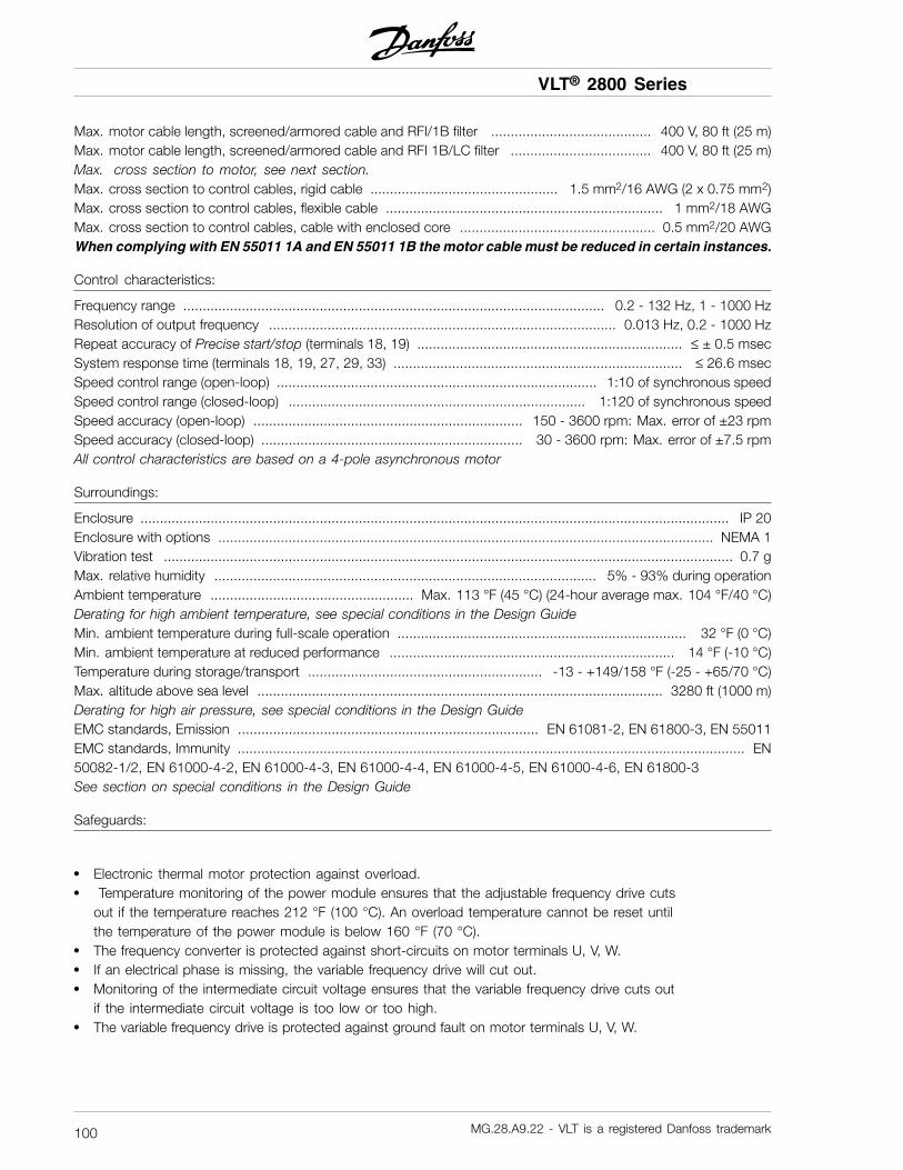
VLT® 2800 Series
Max. motor cable length, screened/armored cable and RFI/1B filter ......................................... 400 V, 80 ft (25 m)Max. motor cable length, screened/armored cable and RFI 1B/LC filter .................................... 400 V, 80 ft (25 m)Max. cross section to motor, see next section.Max. cross section to control cables, rigid cable ................................................ 1.5 mm2/16 AWG (2 x 0.75 mm2)Max. cross section to control cables, flexible cable ....................................................................... 1 mm2/18 AWGMax. cross section to control cables, cable with enclosed core .................................................. 0.5 mm2/20 AWGWhen complying with EN 55011 1A and EN 55011 1B the motor cable must be reduced in certain instances.
Control characteristics:
Frequency range ............................................................................................................ 0.2 - 132 Hz, 1 - 1000 HzResolution of output frequency ......................................................................................... 0.013 Hz, 0.2 - 1000 HzRepeat accuracy of Precise start/stop (terminals 18, 19) .................................................................... ≤ ± 0.5 msecSystem response time (terminals 18, 19, 27, 29, 33) .......................................................................... ≤ 26.6 msecSpeed control range (open-loop) .................................................................................. 1:10 of synchronous speedSpeed control range (closed-loop) ............................................................................ 1:120 of synchronous speedSpeed accuracy (open-loop) ..................................................................... 150 - 3600 rpm: Max. error of ±23 rpmSpeed accuracy (closed-loop) ................................................................... 30 - 3600 rpm: Max. error of ±7.5 rpmAll control characteristics are based on a 4-pole asynchronous motor
Surroundings:
Enclosure ....................................................................................................................................................... IP 20Enclosure with options ............................................................................................................................... NEMA 1Vibration test .................................................................................................................................................. 0.7 gMax. relative humidity .................................................................................................. 5% - 93% during operationAmbient temperature .................................................... Max. 113 °F (45 °C) (24-hour average max. 104 °F/40 °C)Derating for high ambient temperature, see special conditions in the Design GuideMin. ambient temperature during full-scale operation .......................................................................... 32 °F (0 °C)Min. ambient temperature at reduced performance ......................................................................... 14 °F (-10 °C)Temperature during storage/transport ............................................................ -13 - +149/158 °F (-25 - +65/70 °C)Max. altitude above sea level ........................................................................................................ 3280 ft (1000 m)Derating for high air pressure, see special conditions in the Design GuideEMC standards, Emission ............................................................................. EN 61081-2, EN 61800-3, EN 55011EMC standards, Immunity .................................................................................................................................. EN50082-1/2, EN 61000-4-2, EN 61000-4-3, EN 61000-4-4, EN 61000-4-5, EN 61000-4-6, EN 61800-3See section on special conditions in the Design Guide
Safeguards:
• Electronic thermal motor protection against overload.• Temperature monitoring of the power module ensures that the adjustable frequency drive cuts
out if the temperature reaches 212 °F (100 °C). An overload temperature cannot be reset untilthe temperature of the power module is below 160 °F (70 °C).
• The frequency converter is protected against short-circuits on motor terminals U, V, W.• If an electrical phase is missing, the variable frequency drive will cut out.• Monitoring of the intermediate circuit voltage ensures that the variable frequency drive cuts out
if the intermediate circuit voltage is too low or too high.• The variable frequency drive is protected against ground fault on motor terminals U, V, W.
MG.28.A9.22 - VLT is a registered Danfoss trademark100

VLT® 2800 Series
■ Technical data, mains supply 1 x 220 -240 V/3 x 200-240V
According to international standards Type 22803 2805 2807 2811 2815 2822 2840Output current IINV. [A] 2.2 3.2 4.2 6.0 6.8 9.6 16(3 x 200-240V) IMAX (60s) [A] 3.5 5.1 6.7 9.6 10.8 15.3 25.6Output power (230 V) SINV. [KVA] 0.9 1.3 1.7 2.4 2.7 3.8 6.4Typical shaft output PM,N [kW] 0.37 0.55 0.75 1.1 1.5 2.2 3.7Typical shaft output PM,N [HP] 0.5 0.75 1.0 1.5 2.0 3.0 5.0Max. cable crosssection, motor
[mm2/AWG] 1) 4/10 4/10 4/10 4/10 4/10 4/10 4/10
Input current IL,N [A] 5.9 8.3 10.6 14.5 15.2 - -(1 x 220-240 V) IL,MAX (60s) [A] 9.4 13.3 16.7 23.2 24.3 - -Input current IL,N [A] 2.9 4.0 5.1 7.0 7.6 8.8 14.7(3 x 200-240 V) IL,MAX (60s) [A] 4.6 6.4 8.2 11.2 12.2 14.1 23.5Max. cable crosssection, power
[mm2/AWG] 1) 4/10 4/10 4/10 4/10 4/10 4/10 4/10
Max. pre-fuses IEC/UL2) [A] 20/20 20/20 20/20 20/20 20/20 20/20 25/25Efficiency3) [%] 95 95 95 95 95 95 95Power loss at 100%load
[W] 24 35 48 69 94 125 231
Weight [lb]/[kg] 4.4/2.0 4.4/2.0 4.4/2.0 4.4/2.0 4.4/2.0 8.2/3.7 13.2/6.0Enclosure4 type IP 20 IP 20 IP 20 IP 20 IP 20 IP 20 IP 20
1. American Wire Gauge. Max. cable crosssection is the largest cable cross section that canbe attached to the terminals. Always observenational and local regulations.2. Type gG pre-fuses must be used for installationaccording to IEC rules. If you want to maintain UL/cULyou must use pre-fuses of the type Bussmann KTN-R200 V, KTS-R 500 V or Ferraz Shawmut, type ATMR(max. 30A). The fuses must be placed for protectionin a circuit that is capable of supplying a maximum of100,000 amps RMS (symmetrical), 500 V maximum.3. Measured using a 65.5 ft (25 m) shielded/armouredmotor cable with a rated load and rated frequency.4. IP20 is standard for VLT 2805-2875, whereasNEMA 1 is an option.
MG.28.A9.22 - VLT is a registered Danfoss trademark 101
All
abou
t VLT
2800

VLT® 2800 Series
■ Technical data, AC line supply 3 x 380 - 480 V
According to international standards Type 22805 2807 2811 2815 2822 2830
Output current IINV. [A] 1.7 2.1 3.0 3.7 5.2 7.0
(3 x 380-480V) IMAX (60s) [A] 2.7 3.3 4.8 5.9 8.3 11.2
Output power (400 V) SINV. [KVA] 1.1 1.7 2.0 2.6 3.6 4.8
Typical shaft output PM,N [kW] 0.55 0.75 1.1 1.5 2.2 3.0
Typical shaft output PM,N [HP] 0.75 1.0 1.5 2.0 3.0 4.0
Max. cable cross
section, motor
[mm2/AWG] 1) 4/10 4/10 4/10 4/10 4/10 4/10
Input current IL,N [A] 1.6 1.9 2.6 3.2 4.7 6.1
(3 x 380-480 V) IL,MAX(60s)[A] 2.6 3.0 4.2 5.1 7.5 9.8
Max. cable cross
section, power
[mm2/AWG] 1) 4/10 4/10 4/10 4/10 4/10 4/10
Max. pre-fuses IEC/UL2) [A] 20/20 20/20 20/20 20/20 20/20 20/20
Efficiency3) [%] 96 96 96 96 96 96
Power loss at 100%
load
[W] 28 38 55 75 110 150
Weight [lb]/[kg] 4.6/2.1 4.6/2.1 4.6/2.1 4.6/2.1 8.2/3.7 8.2/3.7
Enclosure4 type IP 20 IP 20 IP 20 IP 20 IP 20 IP 20
According to international standards Type 22840 2855 2875 2880 2881 2882
Output current IINV. [A] 9.1 12 16 24 32.0 37.5
(3 x 380-480V) IMAX (60s) [A] 14.5 19.2 25.6 38.4 51.2 60.0
Output power (400 V) SINV. [KVA] 6.3 8.3 11.1 16.6 22.2 26.0
Typical shaft output PM,N [kW] 4.0 5.5 7.5 11.0 15.0 18.5
Typical shaft output PM,N [HP] 5.0 7.5 10.0 15.0 20.0 25.0
Max. cable cross
section, motor
[mm2/AWG] 1) 4/10 4/10 4/10 16/6 16/6 16/6
Input current IL,N [A] 8.1 10.6 14.9 24.0 32.0 37.5
(3 x 380-480 V) IL,MAX(60s)[A] 13.0 17.0 23.8 38.4 51.2 60
Max. cable cross
section, power
[mm2/AWG] 1) 4/10 4/10 4/10 16/6 16/6 16/6
Max. pre-fuses IEC/UL2) [A] 20/20 25/25 25/25 50/50 50/50 50/50
Efficiency3) [%] 96 96 96 97 97 97
Power loss at 100%
load
[W] 200 275 372 412 562 693
Weight [lb]/[kg] 3.7/8.2 13.2/6.0 13.2/6.0 40.8/18.5 40.8/18.5 40.8/18.5
Enclosure4 type IP20 IP20 IP20 IP20/
NEMA 1
IP20/
NEMA 1
IP20/
NEMA 1
1. American Wire Gauge. Max. cable crosssection is the largest cable cross section that canbe attached to the terminals. Always observenational and local regulations.2. Type gG pre-fuses must be used for installationaccording to IEC rules. If you want to maintain UL/cULyou must use pre-fuses of the type Bussmann KTN-R200 V, KTS-R 500 V or Ferraz Shawmut, type ATMR(max. 30A). The fuses must be placed for protection
in a circuit that is capable of supplying a maximum of100,000 amps RMS (symmetrical), 500 V maximum.3. Measured using a 65.5 ft (25 m) shielded/armouredmotor cable with a rated load and rated frequency.4. IP20 is standard for VLT 2805-2875, whereasNEMA 1 is an option.
MG.28.A9.22 - VLT is a registered Danfoss trademark102

VLT® 2800 Series
■ Available literature
■ Supplied with the unitBelow is a list of the literature available for VLT2800. It must be noted that there may be deviationsfrom one country to the next.
Supplied with the unit:
Operating instructions ....................................................................................................................... MG.28.AX.YY
Various literature for VLT 2800:
Data sheet ....................................................................................................................................... MD.28.AX.YY
Instructions for VLT 2800:
LCP remote-mounting kit .................................................................................................................... MI.56.AX.51Filter instruction .................................................................................................................................. MI.28.B1.02VLT 2800 DeviceNet cable ................................................................................................................... MI.28.F1.02Cold plate ........................................................................................................................................... MI.28.D1.02Precise stop ........................................................................................................................................ MI.28.C1.02
Communication with VLT 2800:
Profibus manual ................................................................................................................................ MG.90.AX.YYVLT 2800 DeviceNet manual ............................................................................................................. MG.90.BX.YYX = version numberYY = language version
MG.28.A9.22 - VLT is a registered Danfoss trademark 103
All
abou
t VLT
2800

VLT® 2800 Series
■ Parameter list with factory settings
PNU#
Parameterdescription
Factory setting 4-setup Conv.index
Datatype
001 Language English No 0 5002 Local/remote operation Remote-controlled Yes 0 5003 Local reference 000,000.000 Yes -3 4004 Active Setup setup 1 No 0 5005 Programming Setup Active Setup No 0 5006 Setup copying No copying No 0 5007 LCP copy No copying No 0 5008 Display scaling 1.00 Yes -2 6009 Large display readout Frequency [Hz] Yes 0 5010 Small display line 1.1 REFERENCE % Yes 0 5011 Small display line 1.2 Motor current [A] Yes 0 5012 Small display line 1.3 Power[kW] Yes 0 5013 Local control Remote control
as par. 100Yes 0 5
014 Local stop/reset Active Yes 0 5015 Local jog Not active Yes 0 5016 Local reverse Not active Yes 0 5017 Local reset of trip Active Yes 0 5018 Data change lock Not locked Yes 0 5019 Operating status at
power upForced stop,use saved ref.
Yes 0 5
020 Lock for Hand mode Active No 0 5024 User-defined Quick Menu Not active No 0 5025 Quick Menu Setup 000 No 0 6
4-Setup:’Yes’ means that the parameter can be programmedindividually in each of the four Setups, i.e. one singleparameter can have four different data values. ’No’means that the data value will be the same in all Setups.
Conversion index:This number refers to a conversion figure to be usedwhen writing or reading via serial communicationwith a variable frequency drive.See Data character in Serial communicationin the Design Guide.
Data type:Data type shows the type and length of the telegram.
Data type Description3 Integer 164 Integer 325 Unsigned 86 Unsigned 167 Unsigned 329 Text string
MG.28.A9.22 - VLT is a registered Danfoss trademark104

VLT® 2800 Series
PNU#
Parameterdescription
Factory setting 4-setup Conv.index
Data-type
100 Configuration Speed reg., open loop Yes 0 5101 Torque characteristics Constant torque Yes 0 5102 Motor power PM,N depends on unit Yes 1 6103 Motor voltage UM,N depends on unit Yes -2 6104 Motor frequency fM,N 50 Hz Yes -1 6105 Motor current IM,N depends on motor selected Yes -2 7106 Rated motor speed depends on par. 102 Yes 0 6107 Automatic motor adjustment Optimization off Yes 0 5108 Stator resistance RS depends on motor selected Yes -3 7109 Stator reactance XS depends on motor selected Yes -2 7117 Resonance damping OFF Yes 0 6119 High start torque 0.0 sec Yes -1 5120 Start delay 0.0 sec Yes -1 5121 Start function Coast in start del. Yes 0 5122 Function at stop Coast Yes 0 5123 Min. freq. for activation of
par. 1220.1 Hz Yes -1 5
126 DC braking time 10 sec. Yes -1 6127 DC brake engaging frequency OFF Yes -1 6128 Thermal motor protection No protection Yes 0 5130 Start frequency 0.0 Hz Yes -1 5131 Voltage at start 0.0 V Yes -1 6132 DC brake voltage 0% Yes 0 5133 Start voltage depends on unit Yes -2 6134 Load compensation 100 % Yes -1 6135 U/f-ratio depends on unit Yes -2 6136 Slip compensation 100 % Yes -1 3137 DC hold voltage 0% Yes 0 5138 Brake cut out value 3.0 Hz Yes -1 6139 Brake cut in frequency 3.0 Hz Yes -1 6140 Current, minimum value 0% Yes 0 5142 Leak reactance depends on motor selected Yes -3 7143 Internal ventilator control Automatic Yes 0 5144 AC brake factor 1.30 Yes -2 5146 Reset voltage vector Off Yes 0 5
MG.28.A9.22 - VLT is a registered Danfoss trademark 105
All
abou
t VLT
2800

VLT® 2800 Series
PNU#
Parameterdescription
Factory setting 4-setup Conv.index
Datatype
200 Output frequency range Clockwise only, 0-132 Hz Yes 0 5201 Output frequency,
low limit fMIN
0.0 Hz Yes -1 6
202 Output frequency,high limit fMAX
132 Hz Yes -1 6
203 Reference range Min ref.-Max ref. Yes 0 5204 Minimum ref RefMIN 0.000 Hz Yes -3 4205 Maximum ref RefMAX 50.000 Hz Yes -3 4206 Ramp type Linear Yes 0 5207 Ramp-up time 1 3.00 sec. Yes -2 7208 Ramp-down time 1 3.00 sec. Yes -2 7209 Ramp-up time 2 3.00 sec. Yes -2 7210 Ramp-down time 2 3.00 sec. Yes -2 7211 Jog ramp time 3.00 sec. Yes -2 7212 Quick stop ramp-down time 3.00 sec. Yes -2 7213 Jog frequency 10.0 Hz Yes -1 6214 Reference function Sum Yes 0 5215 Preset reference 1 0.00% Yes -2 3216 Preset reference 2 0.00% Yes -2 3217 Preset reference 3 0.00% Yes -2 3218 Preset reference 4 0.00% Yes -2 3219 Catch up/slow down
reference0.00% Yes -2 6
221 Current limit 160 % Yes -1 6223 Warn. Low current 0.0 A Yes -1 6224 Warn. High current IMAX Yes -1 6225 Warn. Low frequency 0.0 Hz Yes -1 6226 Warn. High frequency 132.0 Hz Yes -1 6227 Warn. Low Feedback -4000.000 Yes -3 4228 Warn. High Feedback 4000.000 Yes -3 4229 Frequency bypass,
bandwidth0 Hz (OFF) Yes 0 6
230 Frequency bypass 1 0.0 Hz Yes -1 6231 Frequency bypass 2 0.0 Hz Yes -1 6
MG.28.A9.22 - VLT is a registered Danfoss trademark106

VLT® 2800 Series
PNU#
Parameterdescription
Factory setting 4-setup Conv.index
Datatype
302 Digital input, term. 18 Start Yes 0 5303 Digital input, term. 19 Reverse Yes 0 5304 Digital input, term. 27 Reset and coast
inverseYes 0 5
305 Digital input, term. 29 Jog Yes 0 5307 Digital input, term. 33 No function Yes 0 5308 Term. 53, analog input voltage REFERENCE % Yes 0 5309 Term. 53, min scaling 0.0 V Yes -1 6310 Term. 53, max scaling 10.0 V Yes -1 6314 Term. 60, analog input current No function Yes 0 5315 Term. 60, min scaling 0.0 mA Yes -4 6316 Term. 60, max scaling 20.0 mA Yes -4 6317 Time out 10 sec. Yes -1 5318 Function after timeout No function Yes 0 5319 Term. 42, analog output 0-IMAX = 0-20 mA Yes 0 5323 Relay output Control ready Yes 0 5327 Pulse ref./FB 5000 Hz Yes 0 7341 Term. 46 digital output Control ready Yes 0 5342 Term. 46 Max. pulse output 5000 Hz Yes 0 6343 Precise stop function Normal ramp stop Yes 0 5344 Counter value 100000 pulses Yes 0 7349 Speed comp delay 10 ms Yes -3 6
4-Setup:’Yes’ means that the parameter can be programmedindividually in each of the four Setups, i.e. one singleparameter can have four different data values. ’No’means that the data value will be the same in all Setups.
Conversion index:This number refers to a conversion figure to be usedwhen writing or reading via serial communicationwith a variable frequency drive.See Data character in Serial communicationin the Design Guide.
Data type:Data type shows the type and length of the telegram.
Data type Description3 Integer 164 Integer 325 Unsigned 86 Unsigned 167 Unsigned 329 Text string
MG.28.A9.22 - VLT is a registered Danfoss trademark 107
All
abou
t VLT
2800

VLT® 2800 Series
PNU#
Parameterdescription
Factory setting 4-setup Conv.index
Datatype
400 Brake function Depends on unit type No 0 5405 Reset function Manual reset Yes 0 5406 Aut. restart time 5 sec. Yes 0 5409 Trip delay overcurrent Off (61 sec.) Yes 0 5411 Switching frequency 4.5 kHz Yes 0 6412 Var. carrier frequency No LC-filter Yes 0 5413 Overmodulation function On Yes 0 5414 Min. feedback 0.000 Yes -3 4415 Max. feedback 1500.000 Yes -3 4416 Process units No unit Yes 0 5417 Speed PID propor.ampl. 0.010 Yes -3 6418 Speed PID intergra. 100 ms Yes -5 7419 Speed PID differentiation time 20.00 ms Yes -5 7420 Speed PID diff. amplification
limit5.0 Yes -1 6
421 Speed PID lowpass filter 20 ms Yes -3 6423 U1 voltage par. 103 Yes -1 6424 F1 frequency Par. 104 Yes -1 6425 U2 voltage par. 103 Yes -1 6426 F2 frequency par. 104 Yes -1 6427 U3 voltage par. 103 Yes -1 6428 F3 frequency par. 104 Yes -1 6437 Proc. PID no/inv. Normal Yes 0 5438 Proc. PID anti wind. Active Yes 0 5439 Proc. PID start frequency Par. 201 Yes -1 6440 Proc. PID start
proportional ampl.0.01 Yes -2 6
441 Proc. PID integration time Off (9999.99 s) Yes -2 7442 Proc. PID differentiation time Off (0.00 s). Yes -2 6443 Proc. PID diff. ampl. limit 5.0 Yes -1 6444 Proc. PID lowpass filter time 0.02 s Yes -2 6445 Flying start Not possible Yes 0 5451 Speed PID feedforward factor 100% Yes 0 6452 Controller range 10 % Yes -1 6456 Brake voltage reduce 0 Yes 0 5461 Feedback conversion Linear Yes 0 5
MG.28.A9.22 - VLT is a registered Danfoss trademark108

VLT® 2800 Series
PNU # Parameter description Factory setting 4-setup Conv.index Datatype
500 Address 1 No 0 5
501 Baudrate 9600 Baud No 0 5
502 Coasting stop Logic or Yes 0 5
503 Quick stop Logic or Yes 0 5
504 DC brake Logic or Yes 0 5
505 Start Logic or Yes 0 5
506 Reversing Logic or Yes 0 5
507 Selection of Setup Logic or Yes 0 5
508 Selection of preset ref. Logic or Yes 0 5
509 Bus jog 1 10.0 Hz Yes -1 6
510 Bus jog 2 10.0 Hz Yes -1 6
512 Telegram profile FC protocol Yes 0 5
513 Bus time interval 1 sec. Yes 0 5
514 Bus time interval function Off Yes 0 5
515 Data readout: Reference % No -1 3
516 Data readout: Reference [unit] No -3 4
517 Data readout: Feedback [unit] No -3 4
518 Data readout: Frequency No -1 3
519 Data readout: Frequency x scaling No -1 3
520 Data readout: Motor current No -2 7
521 Data readout: Torque No -1 3
522 Data readout: Power [kW] No -2 7
523 Data readout: Power [HP] No -2 7
524 Data readout: Motor voltage [V] No -1 6
525 Data readout: DC Link voltage No 0 6
526 Data readout: Motor thermal load No 0 5
527 Data readout: Inverter thermal load No 0 5
528 Data readout: Digital input No 0 5
529 Data readout: Analog input, term. 53 No -1 5
531 Data readout: Analog input, term. 60 No -4 5
532 Data readout: Pulse reference No -1 7
533 Data readout: External reference No -1 6
534 Data readout: Status word No 0 6
537 Data readout: Inverter temperature No 0 5
538 Data readout: Alarm word No 0 7
539 Data readout: Control word No 0 6
540 Data readout: Warning word No 0 7
541 Data readout: Extended status word No 0 7
544 Data readout: Pulse Count No 0 7
MG.28.A9.22 - VLT is a registered Danfoss trademark 109
All
abou
t VLT
2800

VLT® 2800 Series
PNU#
Parameterdescription
Factory setting 4-setup Conv.index
Datatype
600 Operating hours No 73 7601 Hours run No 73 7602 kWh counter No 2 7603 Number of cut ins No 0 6604 Number of overheatings No 0 6605 Number of overvoltages No 0 6615 Fault log: Error code No 0 5616 Fault log: TIME No 0 7617 Fault log: Value: No 0 3618 Reset of kWh counter No reset No 0 7619 Reset of running hours counter No reset No 0 5620 Operation mode Normal operation No 0 5621 Nameplate: Unit type No 0 9624 Nameplate: Software version No 0 9625 Nameplate: LCP identification no. No 0 9626 Nameplate: Database identification no. No -2 9627 Nameplate: Power parts version No 0 9628 Nameplate: Application option type No 0 9630 Nameplate: Communication option type No 0 9632 Nameplate: BMC software identification No 0 9634 Nameplate: Unit identification for communication No 0 9635 Nameplate: Software parts no. No 0 9640 Software version No -2 6641 BMC software identification No -2 6642 Power card identification No -2 6
4-Setup:’Yes’ means that the parameter can be programmedindividually in each of the four Setups, i.e. one singleparameter can have four different data values. No’means that the data value will be the same in all Setups.
Conversion index:This number refers to a conversion figure to be usedwhen writing or reading via serial communicationwith a variable frequency drive.See Data character in Serial communicationin the Design Guide.
Data type:Data type shows the type and length of the telegram.
Data type Description3 Integer 164 Integer 325 Unsigned 86 Unsigned 167 Unsigned 329 Text string
MG.28.A9.22 - VLT is a registered Danfoss trademark110

VLT® 2800 Series
Inde
x
■ Index
AAC brake .................................................................... 67
AC line connection ........................................................ 17
Active Setup ................................................................ 32
Address...................................................................... 75
Analog output .............................................................. 62
Analogue input ............................................................. 60
Automatic motor tuning............................................. 26, 42
BBaudrate..................................................................... 75
Brake connection.......................................................... 18
Brake cut in frequency ................................................... 48
Brake cut out value ....................................................... 48
Brake function.............................................................. 67
Brake resistance........................................................... 19
Brake Voltage Reduce ................................................... 74
Bus jog....................................................................... 80
Bus time interval ........................................................... 80
Ccontrol panel................................................................ 25
Catch up .................................................................... 54
CHANGE DATA ............................................................ 25
Connection of a 2-wire transmitter .................................... 23
Constant torque ........................................................... 40
Control keys ................................................................ 25
Control terminals .......................................................... 19
Control unit ................................................................. 25
Control wires ............................................................... 20
Counter value .............................................................. 66
Current limit, ................................................................ 54
Current, minimum value.................................................. 48
DDC brake time.............................................................. 45
DC brake voltage .......................................................... 46
DC hold voltage............................................................ 48
Derating for ambient temperature ..................................... 30
Diagram...................................................................... 14
Digital / pulse output...................................................... 64
Digital inputs................................................................ 58
Dimensions ................................................................... 6
Direction of motor rotation .............................................. 17
Display mode............................................................... 26
Display readout ....................................................... 26, 28
Display scaling of output frequency ................................... 34
EElectrical installation ...................................................... 15
Electrical installation, control circuitry ................................. 20
EMC-correct electrical installation ..................................... 12
ETR - Electronic Thermal Relay ........................................ 45
Extreme environments ................................................... 95
FFan control .................................................................. 48
Fault log ..................................................................... 85
Feedback,................................................................... 68
Flying start .................................................................. 73
Four Setups................................................................. 33
Frequence bypass, bandwidth ......................................... 56
Function at stop ........................................................... 44
GGain AC brake ............................................................. 49
Galvanic isolation (PELV)................................................. 95
Ground connection ....................................................... 18
Grounding................................................................... 11
Grounding of shielded/armoured control cables ................... 13
HHand / Auto mode operation ........................................... 28
Hand mode ................................................................. 38
High voltage test........................................................... 11
High voltage warning ..................................................5, 11
IInitialize....................................................................... 86
Input fuses .................................................................. 17
IP 21 solution................................................................. 7
JJog frequency .............................................................. 53
Jog ramp time.............................................................. 53
L
MG.28.A9.22 - VLT is a registered Danfoss trademark 111

VLT® 2800 Series
Language.................................................................... 32
Large display readout .................................................... 34
LCP copy.................................................................... 33
Leakage reactance........................................................ 48
Literature ...................................................................103
Load compensation....................................................... 47
Load sharing................................................................ 19
Local reference............................................................. 32
Lock for data changes ................................................... 37
MMains supply ..............................................................101
Manual initialization........................................................ 25
Maximum Pulse 29........................................................ 64
Mechanical installation ................................................... 10
Menu mode............................................................ 26, 26
Motor cables ............................................................... 18
Motor coils .................................................................... 7
Motor connection ......................................................... 17
Motor current............................................................... 42
Motor frequency ........................................................... 41
Motor power................................................................ 41
Motor thermal protection ................................................ 17
Motor voltage............................................................... 41
OOperating mode at power-up, local operation...................... 38
Output frequency.......................................................... 50
Overmodulation function ................................................ 68
PParallel connection of motors........................................... 18
Parameter list with factory settings...................................104
Potentiometer reference ................................................. 23
Precise stop function ..................................................... 65
Preset reference ........................................................... 54
Process control, closed loop ........................................... 40
Process PID ................................................................ 72
Process units ............................................................... 69
Programming Setup ...................................................... 33
Protocol...................................................................... 83
Pulse start/stop ............................................................ 23
Pulse/reference feedback ............................................... 64
QQUICK MENU .................................................... 25, 26, 26
Quick Menu setup......................................................... 38
Quick menu, userdefined ................................................ 38
Quick stop ramp-down time ........................................... 53
Rreverse ....................................................................... 58
Ramp type .................................................................. 51
Ramp-down time.......................................................... 52
Ramp-up time.............................................................. 52
Rated motor speed ....................................................... 42
Recidual Current Device ................................................. 19
Reference function ........................................................ 53
Reference, .................................................................. 51
Relative ...................................................................... 53
Relay connection .......................................................... 21
Relay output 1-3........................................................... 63
Reset function.............................................................. 67
Reset voltage vector ...................................................... 49
Resonance damping...................................................... 43
RFI 1B filter ................................................................... 7
SSlow down .................................................................. 54
Setup copying.............................................................. 33
Side-by-side ................................................................ 10
Slip compensation ........................................................ 47
Spacing for mechanical installation.................................... 10
Special motor mode ...................................................... 40
Speed comp delay ........................................................ 66
Speed control, closed loop ............................................. 40
Speed control, open loop ............................................... 40
Speed PID .................................................................. 69
Speed up/slow down..................................................... 23
Start .......................................................................... 73
Start delay................................................................... 44
Start frequency............................................................. 46
Start function ............................................................... 44
Start torque ................................................................. 44
Start voltage ................................................................ 47
Start/stop ................................................................... 23
Stator reactance ........................................................... 43
Stator resistance........................................................... 42
Status LED.................................................................. 25
STOP/RESET............................................................... 25
Sub D plug.................................................................. 22
Sum .......................................................................... 53
Switching frequency ...................................................... 68
MG.28.A9.22 - VLT is a registered Danfoss trademark112

VLT® 2800 Series
Inde
x
TTelegram Profile ............................................................ 80
Temperature-related switching frequency............................ 30
Terminal 42.................................................................. 62
Terminal 46.................................................................. 64
Terminal 53.................................................................. 60
Terminal 60.................................................................. 61
Terminal cover................................................................ 7
Terminals .................................................................... 23
Thermal motor protection ............................................... 45
Thermistor.............................................................. 46, 59
Tightening Torque, Power Terminals .................................. 19
Time out ..................................................................... 61
Torque characteristic ..................................................... 40
UU/f-ratio ...................................................................... 47
UL Standard ................................................................ 95
VVariable torque ............................................................. 40
VLT 2800 start-up ......................................................... 30
VLT Software Dialog ...................................................... 22
WWarning functions ........................................................ 54
Warning words, extended status words and alarmwords ....... 94
Warnings/alarm messages and ....................................... 90
Warnings/alarms........................................................... 29
MG.28.A9.22 - VLT is a registered Danfoss trademark 113

Rev. 2005-11-17
www.danfoss.com/drives
195R0027 MG28A922
*MG28A922*