instruction manual - grieve corp information/component s/danf… · vlt 2800 instruction manual...
TRANSCRIPT
MG
27A222
VLT ®
2800In
structio
nM
anu
al
VLT® 2800
Instruction Manual

Contents
Introduction to VLT 2800 3
Software version 3
High voltage warning 4
These rules concern your safety. 4
Warning against unintended start 4
Installation 6
Mechanical dimensions 6
Mechanical installation 10
General information about electrical installation 11
EMC-correct electrical installation 12
Grounding of shielded/armored control cables 13
Diagram 14
Electrical installation 15
Safety clamp 17
Prefuses 17
AC line connection 17
Motor connection 18
Direction of motor rotation 19
Motor thermal protection 19
Parallel connection of motors 19
Motor cables 19
Brake connection 20
Ground connection 20
Load sharing 20
Tightening Torque, Power Terminals 21
Calculation of brake resistance 21
Access to control terminals 21
Electrical installation, control circuitry 21
Tightening torques, control cables 22
Electrical installation, control terminals 22
Relay connection 23
VLT Software Dialog 23
Connection examples 24
Control unit 26
Manual initialization 26
Automatic motor tuning 27
Display readout 29
Hand Auto 29
Warnings/alarms 30
Special conditions 31
Temperature-related switching frequency 31
Derating for long motor cables 31
VLT® 2800 Series
MG.27.A2.22 - VLT® is a registered Danfoss trademark 1
VLT 2800 start-up 31
Programming 33
Operation & Display 33
Load and Motor 41
References & Limits 52
Inputs and Outputs 59
Special functions 69
Enhanced Sleep Mode 79
Serial communication 84
Technical functions 93
All about VLT 2800 98
Warnings/alarm messages 98
Warning words, extended status words and alarmwords 102
Special conditions 103
Extreme environments 103
Galvanic Isolation (PELV) 103
UL Standard 104
General technical data 105
Technical data, mains supply 1 x 220 - 240 V/3 x 200-240V 110
Technical data, mains supply 3 x 380 - 480 V 111
Available literature 112
Supplied with the unit 112
VLT® 2800 Series
2 MG.27.A2.22 - VLT® is a registered Danfoss trademark
VLT 2800Instruction Manual
Software version: 3.1x
This Design Guide can be used for all VLT 2800 series adjustable frequency drives with software version 3.1x.The software version number is indicated in parameter 640.
WarningIt can be extremely dangerous to touch the electrical parts, even when the line supply has been disconnected.Also ensure that other voltage inputs are disconnected from load sharing through the DC bus.Wait at least 4 minutes after the input power has been removed before servicing the drive.
VLT® 2800 Series
MG.27.A2.22 - VLT® is a registered Danfoss trademark 3
Intr
oduc
tion
to V
LT 2
800
High voltage warning
The voltage of the frequency converter isdangerous whenever the converter is con-nected to mains. Incorrect fitting of themotor or frequency converter may causedamage to the equipment, serious injuryor death. Consequently, it is essential tocomply with the instructions in this manualas well as local and national rules andsafety regulations.
The Protective Extra Low Voltage (PELV)requirements stated in IEC 61800-5-1 arenot fulfilled at altitudes above 2000 m(6562 ft.). For 200V frequency convertersthe requirements are not fulfilled at alti-tudes above 5000 m (16 404 ft.). Pleasecontact Danfoss Drives for further infor-mation.
These rules concern your safety.
1. The adjustable frequency drive must be dis-connected from AC line if repair work is to becarried out. Ensure that the line supply hasbeen disconnected and that the prescribedtime has passed before removing motor andAC line plugs.
2. The [STOP/RESET] key on the control panelof the adjustable frequency drive does notdisconnect the equipment from line powerand is therefore not to be used as a safetyswitch.
3. The unit must be properly grounded, the usermust be protected against the supply voltage,and the motor must be protected againstoverloading in accordance with prevailing na-tional and local regulations.
4. The ground leakage currents are higher than3.5 mA.
5. Protection against motor overload is not in-cluded in the factory setting. If this function isrequired, set parameter 128 Motor thermalprotection to data value ETR trip or data valueETR warning. For the North American market:The ETR functions provide overload protec-
tion of the motor, class 20, in accordance withNEC.
6. Do not remove either the plugs for the motoror line supply while the adjustable frequencydrive is connected to line power. Ensure thatthe line supply has been disconnected andthat the prescribed time has passed beforeremoving motor and AC line plugs.
7. Note that the adjustable frequency drive hasmore voltage inputs than L1, L2 and L3 whenthe DC bus terminals are used. Check that allvoltage inputs are disconnected and that theprescribed time has passed before repairwork is commenced.
Warning against unintended start
1. The motor can be brought to a stop by meansof digital commands, bus commands, refer-ences or a local stop, while the frequencyconverter is connected to mains. If personalsafety considerations make it necessary toensure that no unintended start occurs, thesestop functions are not sufficient.
2. While parameters are being changed, themotor may start. Consequently, the stop key[STOP/RESET] must always be activated,following which data can be modified.
3. A motor that has been stopped may start iffaults occur in the electronics of the frequen-cy converter, or if a temporary overload or afault in the supply mains or the motor con-nection ceases.
VLT® 2800 Series
4 MG.27.A2.22 - VLT® is a registered Danfoss trademark
Motor overload protection
The electronic thermal relay (ETR) in UL listed VLTsprovides Class 20 motor overload protection in ac-cordance with the NEC in single motor applicationswhen parameter 128 is set for "ETR TRIP" and pa-
rameter 105 Motor current is set for the rated motorcurrent.
WarningIt can be extremely dangerous to touch the electrical parts, even when the line supply has been disconnected.Also ensure that other voltage inputs are disconnected from load sharing through the DC bus.Wait at least 4 minutes after the input power has been removed before servicing the drive.
VLT® 2800 Series
MG.27.A2.22 - VLT® is a registered Danfoss trademark 5
Intr
oduc
tion
to V
LT 2
800
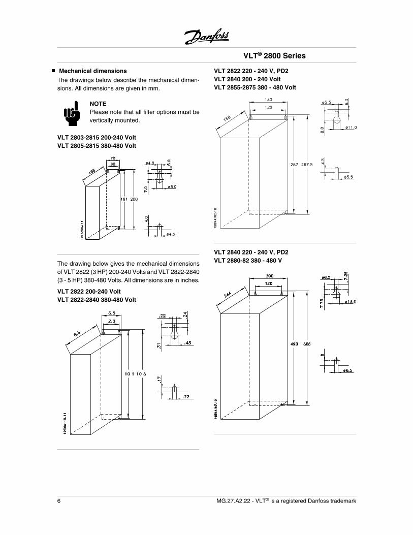
Mechanical dimensions
The drawings below describe the mechanical dimen-sions. All dimensions are given in mm.
NOTEPlease note that all filter options must bevertically mounted.
VLT 2803-2815 200-240 VoltVLT 2805-2815 380-480 Volt
The drawing below gives the mechanical dimensionsof VLT 2822 (3 HP) 200-240 Volts and VLT 2822-2840(3 - 5 HP) 380-480 Volts. All dimensions are in inches.
VLT 2822 200-240 VoltVLT 2822-2840 380-480 Volt
VLT 2822 220 - 240 V, PD2VLT 2840 200 - 240 VoltVLT 2855-2875 380 - 480 Volt
VLT 2840 220 - 240 V, PD2VLT 2880-82 380 - 480 V
VLT® 2800 Series
6 MG.27.A2.22 - VLT® is a registered Danfoss trademark
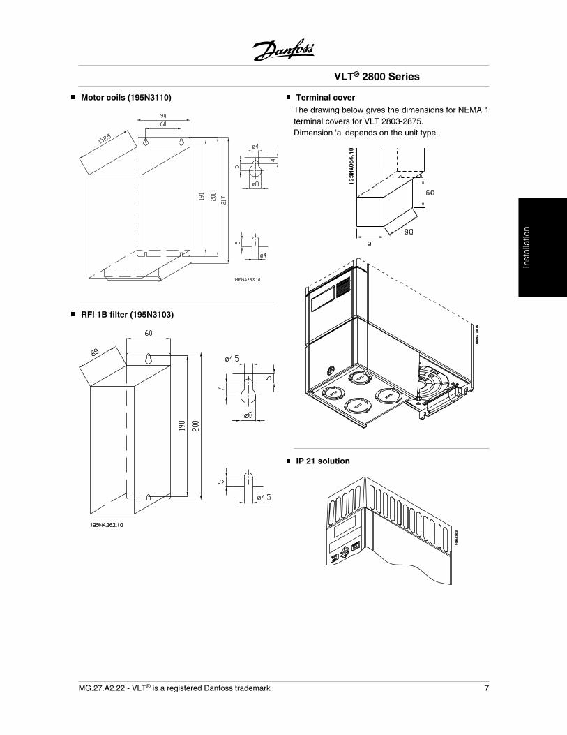
Motor coils (195N3110)
RFI 1B filter (195N3103)
Terminal cover
The drawing below gives the dimensions for NEMA 1terminal covers for VLT 2803-2875.Dimension 'a' depends on the unit type.
IP 21 solution
VLT® 2800 Series
MG.27.A2.22 - VLT® is a registered Danfoss trademark 7
Inst
alla
tion

Dimensions
Type Code number A B CVLT 2803-2815 200-240 V, VLT 2805-2815 380-480 V 195N2118 47 80 170VLT 2822 200-240 V, VLT 2822-2840 380-480 V 195N2119 47 95 170VLT 2840 200-240 V, VLT 2822 PD2, TR1 2855-2875380-480 V
195N2120 47 145 170
TR1 2880-2882 380-480 V, VLT 2840 PD2 195N2126 47 205 245
EMC filter for long motor cables
192H4719
VLT® 2800 Series
8 MG.27.A2.22 - VLT® is a registered Danfoss trademark
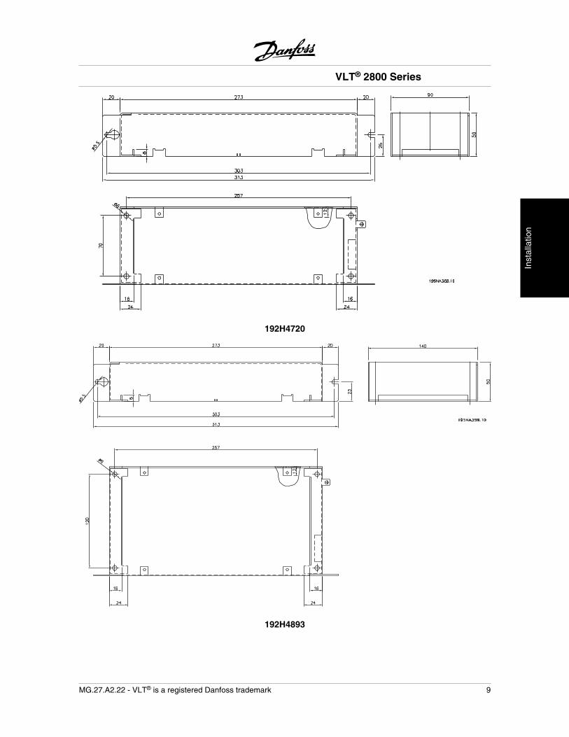
192H4720
192H4893
VLT® 2800 Series
MG.27.A2.22 - VLT® is a registered Danfoss trademark 9
Inst
alla
tion
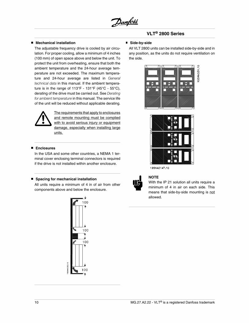
Mechanical installation
The adjustable frequency drive is cooled by air circu-lation. For proper cooling, allow a minimum of 4 inches(100 mm) of open space above and below the unit. Toprotect the unit from overheating, ensure that both theambient temperature and the 24-hour average tem-perature are not exceeded. The maximum tempera-ture and 24-hour average are listed in Generaltechnical data in this manual. If the ambient tempera-ture is in the range of 113°F - 131°F (45°C - 55°C),derating of the drive must be carried out. See Deratingfor ambient temperature in this manual. The service lifeof the unit will be reduced without applicable derating.
The requirements that apply to enclosuresand remote mounting must be compliedwith to avoid serious injury or equipmentdamage, especially when installing largeunits.
Enclosures
In the USA and some other countries, a NEMA 1 ter-minal cover enclosing terminal connectors is requiredif the drive is not installed within another enclosure.
Spacing for mechanical installation
All units require a minimum of 4 in of air from othercomponents above and below the enclosure.
Side-by-side
All VLT 2800 units can be installed side-by-side and inany position, as the units do not require ventilation onthe side.
NOTEWith the IP 21 solution all units require aminimum of 4 in air on each side. Thismeans that side-by-side mounting is notallowed.
VLT® 2800 Series
10 MG.27.A2.22 - VLT® is a registered Danfoss trademark
General information about electrical installation
High voltage warning
The voltage of the adjustable frequencydrive is dangerous whenever the drive isconnected to the AC line. Incorrect instal-lation of the motor or drive may causedamage to the equipment, serious injuryor death. Comply with the safety instruc-tions in this manual as well as local andnational rules and safety regulations.Touching electrical parts may be fatal -even after the equipment has been dis-connected from the AC line. Wait at least4 minutes for current to dissipate.
NOTEIt is the responsibility of the user or instal-ler to ensure correct grounding and pro-tection in accordance with national andlocal standards.
Earthing
Comply with the following at installation:
• Safety earthing: The drive has a high leakagecurrent and must be earthed properly forsafety. Follow all local safety regulations.
• High frequency earthing: Keep earthing con-nections as short as possible.
Connect all earthing SYSTEMs to ensure the lowestpossible conductor impedance. The lowest possibleconductor impedance is achieved by keeping the con-ductor as short as possible and by grounding with thegreatest possible surface area. If multiple drives areinstalled in a cabinet, the cabinet backplate, whichmust be made of metal, should be used as a joint earthreference plate. The drives must be fitted to the back-plate at the lowest possible impedance.
To achieve low impedance, connect the drive to thebackplate with the drive fastening bolts. Remove allpaint from the contact points.
High voltage test
A high voltage test can be performed by short-circuit-ing terminals U, V, W, L1, L2 and L3, and applying amax. of 2,160 V DC in 1 sec. between this short-circuitand terminal 95.
Do not perform a high voltage test be-tween the control terminals and the chas-sis, because the voltage potential of thecontrol card cannot exceed approximately100 volts with respect to chassis due to avoltage limiting circuitry.The terminals are protected against directhazardous access through barriers.
VLT® 2800 Series
MG.27.A2.22 - VLT® is a registered Danfoss trademark 11
Inst
alla
tion
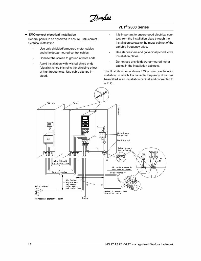
EMC-correct electrical installation
General points to be observed to ensure EMC-correctelectrical installation.
- Use only shielded/armoured motor cablesand shielded/armoured control cables.
- Connect the screen to ground at both ends.
- Avoid installation with twisted shield ends(pigtails), since this ruins the shielding effectat high frequencies. Use cable clamps in-stead.
- It is important to ensure good electrical con-tact from the installation plate through theinstallation screws to the metal cabinet of thevariable frequency drive.
- Use starwashers and galvanically conductiveinstallation plates.
- Do not use unshielded/unarmoured motorcables in the installation cabinets.
The illustration below shows EMC-correct electrical in-stallation, in which the variable frequency drive hasbeen fitted in an installation cabinet and connected toa PLC.
VLT® 2800 Series
12 MG.27.A2.22 - VLT® is a registered Danfoss trademark
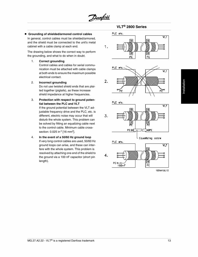
Grounding of shielded/armored control cables
In general, control cables must be shielded/armored,and the shield must be connected to the unit's metalcabinet with a cable clamp at each end.
The drawing below shows the correct way to performthe grounding, and what to do when in doubt.
1. Correct groundingControl cables and cables for serial commu-nication must be attached with cable clampsat both ends to ensure the maximum possibleelectrical contact.
2. Incorrect groundingDo not use twisted shield ends that are plai-ted together (pigtails), as these increaseshield impedance at higher frequencies.
3. Protection with respect to ground poten-tial between the PLC and VLTIf the ground potential between the VLT ad-justable frequency drive and the PLC, etc. isdifferent, electric noise may occur that willdisturb the whole system. This problem canbe solved by fitting an equalizing cable nextto the control cable. Minimum cable cross-
section: 0.025 in 2 [16 mm2].
4. In the event of a 50/60 Hz ground loopIf very long control cables are used, 50/60 Hzground loops can arise, and these can inter-fere with the whole system. This problem isresolved by attaching one end of the shield tothe ground via a 100 nF capacitor (short pinlength).
VLT® 2800 Series
MG.27.A2.22 - VLT® is a registered Danfoss trademark 13
Inst
alla
tion
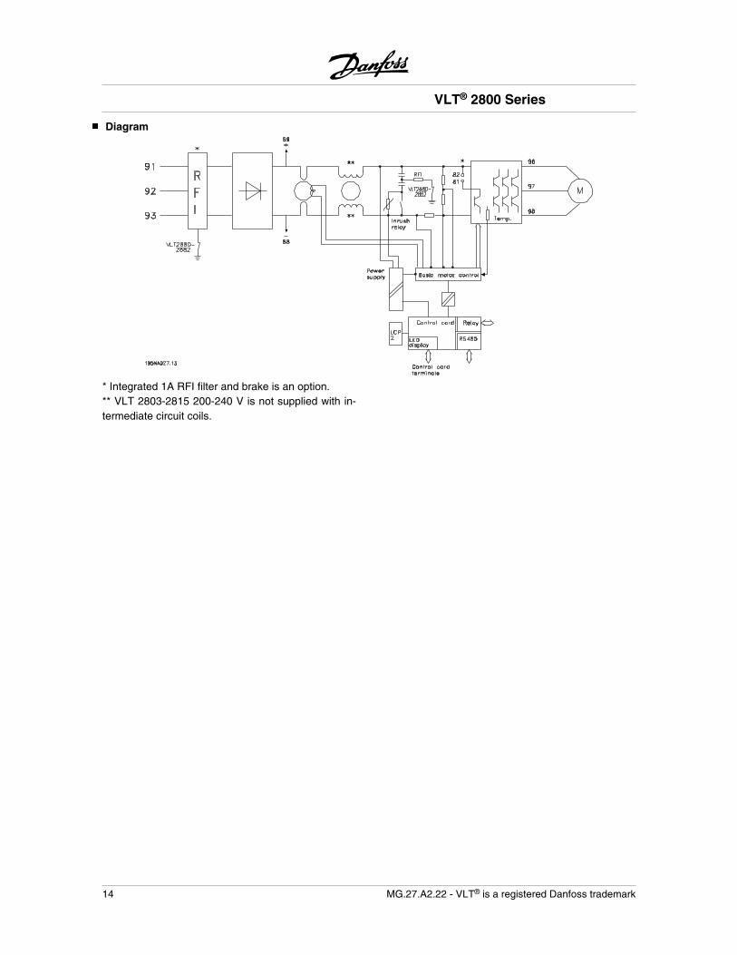
Diagram
* Integrated 1A RFI filter and brake is an option.** VLT 2803-2815 200-240 V is not supplied with in-termediate circuit coils.
VLT® 2800 Series
14 MG.27.A2.22 - VLT® is a registered Danfoss trademark
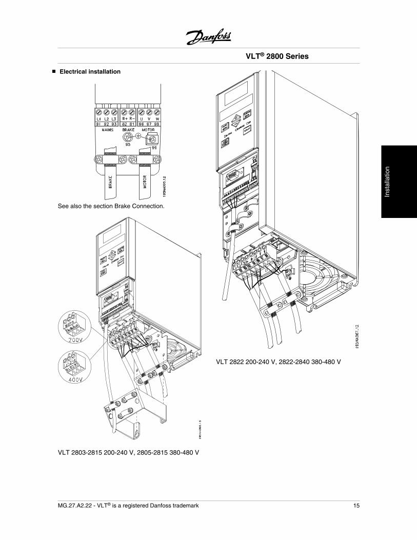
Electrical installation
See also the section Brake Connection.
VLT 2803-2815 200-240 V, 2805-2815 380-480 V
VLT 2822 200-240 V, 2822-2840 380-480 V
VLT® 2800 Series
MG.27.A2.22 - VLT® is a registered Danfoss trademark 15
Inst
all
n
Inst
alla
tion
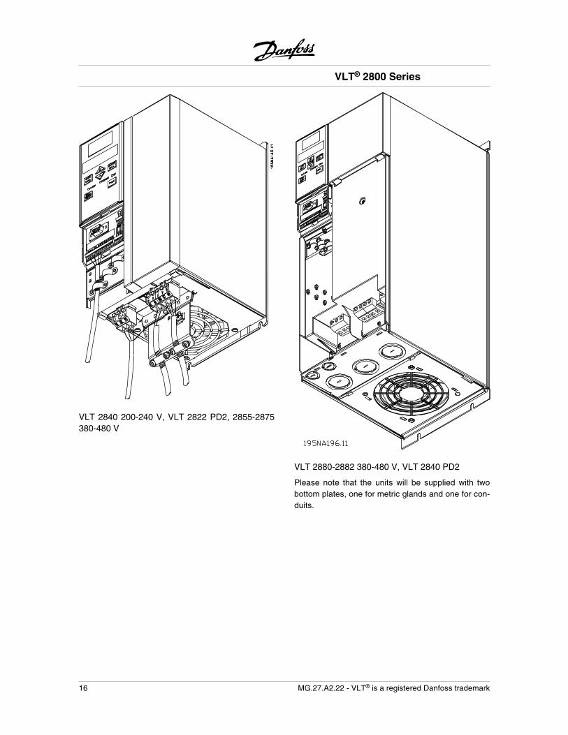
VLT 2840 200-240 V, VLT 2822 PD2, 2855-2875380-480 V
VLT 2880-2882 380-480 V, VLT 2840 PD2
Please note that the units will be supplied with twobottom plates, one for metric glands and one for con-duits.
VLT® 2800 Series
16 MG.27.A2.22 - VLT® is a registered Danfoss trademark
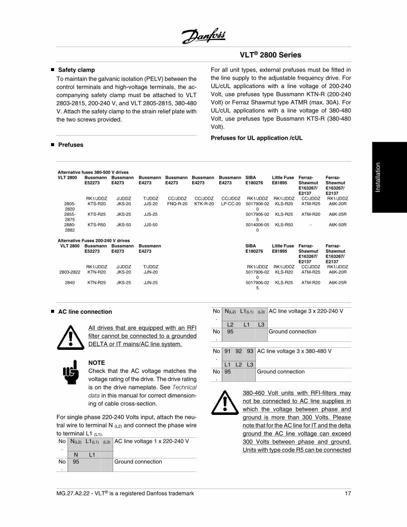
Safety clamp
To maintain the galvanic isolation (PELV) between thecontrol terminals and high-voltage terminals, the ac-companying safety clamp must be attached to VLT2803-2815, 200-240 V, and VLT 2805-2815, 380-480V. Attach the safety clamp to the strain relief plate withthe two screws provided.
Prefuses
For all unit types, external prefuses must be fitted inthe line supply to the adjustable frequency drive. ForUL/cUL applications with a line voltage of 200-240Volt, use prefuses type Bussmann KTN-R (200-240Volt) or Ferraz Shawmut type ATMR (max. 30A). ForUL/cUL applications with a line voltage of 380-480Volt, use prefuses type Bussmann KTS-R (380-480Volt).
Prefuses for UL application /cUL
Alternative fuses 380-500 V drivesVLT 2800 Bussmann
E52273BussmannE4273
BussmannE4273
BussmannE4273
BussmannE4273
BussmannE4273
SIBAE180276
Little FuseE81895
Ferraz-ShawmutE163267/E2137
Ferraz-ShawmutE163267/E2137
RK1/JDDZ J/JDDZ T/JDDZ CC/JDDZ CC/JDDZ CC/JDDZ RK1/JDDZ RK1/JDDZ CC/JDDZ RK1/JDDZ2805-2820
KTS-R20 JKS-20 JJS-20 FNQ-R-20 KTK-R-20 LP-CC-20 5017906-020
KLS-R20 ATM-R25 A6K-20R
2855-2875
KTS-R25 JKS-25 JJS-25 5017906-025
KLS-R25 ATM-R20 A6K-25R
2880-2882
KTS-R50 JKS-50 JJS-50 5014006-050
KLS-R50 - A6K-50R
Alternative Fuses 200-240 V drives
VLT 2800 BussmannE52273
BussmannE4273
BussmannE4273
SIBAE180276
Little FuseE81895
Ferraz-ShawmutE163267/E2137
Ferraz-ShawmutE163267/E2137
RK1/JDDZ J/JDDZ T/JDDZ RK1/JDDZ RK1/JDDZ CC/JDDZ RK1/JDDZ2803-2822 KTN-R20 JKS-20 JJN-20 5017906-02
0KLS-R20 ATM-R25 A6K-20R
2840 KTN-R25 JKS-25 JJN-25 5017906-025
KLS-R25 ATM-R20 A6K-25R
AC line connection
All drives that are equipped with an RFIfilter cannot be connected to a groundedDELTA or IT mains/AC line system.
NOTECheck that the AC voltage matches thevoltage rating of the drive. The drive ratingis on the drive nameplate. See Technicaldata in this manual for correct dimension-ing of cable cross-section.
For single phase 220-240 Volts input, attach the neu-tral wire to terminal N (L2) and connect the phase wireto terminal L1 (L1).No.
N(L2) L1(L1) (L3) AC line voltage 1 x 220-240 V
N L1No.
95 Ground connection
No.
N(L2) L1(L1) (L3) AC line voltage 3 x 220-240 V
L2 L1 L3No.
95 Ground connection
No.
91 92 93 AC line voltage 3 x 380-480 V
L1 L2 L3No.
95 Ground connection
380-460 Volt units with RFI-filters maynot be connected to AC line supplies inwhich the voltage between phase andground is more than 300 Volts. Pleasenote that for the AC line for IT and the deltaground the AC line voltage can exceed300 Volts between phase and ground.Units with type code R5 can be connected
VLT® 2800 Series
MG.27.A2.22 - VLT® is a registered Danfoss trademark 17
Inst
alla
tion
to mains supplies with up to 400 V be-tween phase and ground.
See Technical data for correct dimensioning of cablecross-section.
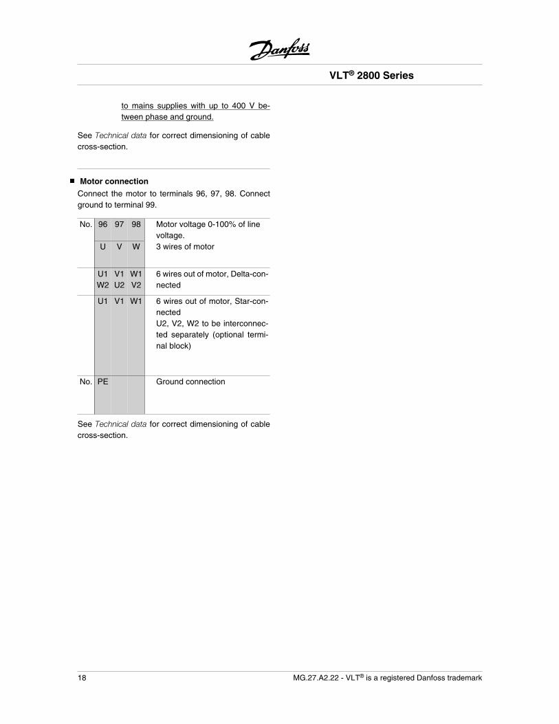
Motor connection
Connect the motor to terminals 96, 97, 98. Connectground to terminal 99.
No. 96 97 98 Motor voltage 0-100% of linevoltage.
U V W 3 wires of motor
U1W2
V1U2
W1V2
6 wires out of motor, Delta-con-nected
U1 V1 W1 6 wires out of motor, Star-con-nectedU2, V2, W2 to be interconnec-ted separately (optional termi-nal block)
No. PE Ground connection
See Technical data for correct dimensioning of cablecross-section.
VLT® 2800 Series
18 MG.27.A2.22 - VLT® is a registered Danfoss trademark
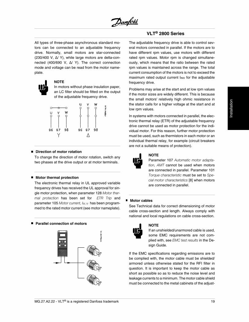
All types of three-phase asynchronous standard mo-tors can be connected to an adjustable frequencydrive. Normally, small motors are star-connected(230/400 V, / Y), while large motors are delta-con-nected (400/690 V, / Y). The correct connectionmode and voltage can be read from the motor name-plate.
NOTEIn motors without phase insulation paper,an LC filter should be fitted on the outputof the adjustable frequency drive.
Direction of motor rotation
To change the direction of motor rotation, switch anytwo phases at the drive output or at motor terminals.
Motor thermal protection
The electronic thermal relay in UL approved variablefrequency drives has received the UL approval for sin-gle motor protection, when parameter 128 Motor ther-mal protection has been set for ETR Trip andparameter 105 Motor current, IM, N has been program-med to the rated motor current (see motor nameplate).
Parallel connection of motors
The adjustable frequency drive is able to control sev-eral motors connected in parallel. If the motors are tohave different rpm values, use motors with differentrated rpm values. Motor rpm is changed simultane-ously, which means that the ratio between the ratedrpm values is maintained across the range. The totalcurrent consumption of the motors is not to exceed themaximum rated output current IINV for the adjustablefrequency drive.
Problems may arise at the start and at low rpm valuesif the motor sizes are widely different. This is becausethe small motors' relatively high ohmic resistance inthe stator calls for a higher voltage at the start and atlow rpm values.
In systems with motors connected in parallel, the elec-tronic thermal relay (ETR) of the adjustable frequencydrive cannot be used as motor protection for the indi-vidual motor. For this reason, further motor protectionmust be used, such as thermistors in each motor or anindividual thermal relay, for example (circuit breakersare not a suitable means of protection).
NOTEParameter 107 Automatic motor adapta-tion, AMT cannot be used when motorsare connected in parallel. Parameter 101Torque characteristic must be set to Spe-cial motor characteristics [8] when motorsare connected in parallel.
Motor cables
See Technical data for correct dimensioning of motorcable cross-section and length. Always comply withnational and local regulations on cable cross-section.
NOTEIf an unshielded/unarmored cable is used,some EMC requirements are not com-plied with, see EMC test results in the De-sign Guide.
If the EMC specifications regarding emissions are tobe complied with, the motor cable must be shielded/armored unless otherwise stated for the RFI filter inquestion. It is important to keep the motor cable asshort as possible so as to reduce the noise level andleakage currents to a minimum. The motor cable shieldmust be connected to the metal cabinets of the adjust-
VLT® 2800 Series
MG.27.A2.22 - VLT® is a registered Danfoss trademark 19
Inst
alla
tion
able frequency drive and the motor. The shield con-nections are to be made with the largest possiblesurface area (cable clamp). This is enabled by differentinstallation devices in different adjustable frequencydrives. Connecting with twisted shield ends (pigtails)is to be avoided, as these spoil the shielding effect athigh frequencies. If it is necessary to break the shieldto install a motor isolator or motor relay. The shieldmust be continued at the lowest possible HF impe-dance.
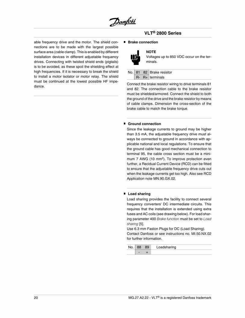
Brake connection
NOTEVoltages up to 850 VDC occur on the ter-minals.
No. 81 82 Brake resistorR- R+ terminals
Connect the brake resistor wiring to drive terminals 81and 82. The connection cable to the brake resistormust be shielded/armored. Connect the shield to boththe ground of the drive and the brake resistor by meansof cable clamps. Dimension the cross-section of thebrake cable to match the brake torque.
Ground connection
Since the leakage currents to ground may be higherthan 3.5 mA, the adjustable frequency drive must al-ways be connected to ground in accordance with ap-plicable national and local regulations. To ensure thatthe ground cable has good mechanical connection toterminal 95, the cable cross section must be a mini-mum 7 AWG (10 mm2). To improve protection evenfurther, a Recidual Current Device (RCD) can be fittedto ensure that the adjustable frequency drive cuts outwhen the leakage currents get too high. Also see RCDApplication note MN.90.GX.02.
Load sharing
Load sharing provides the facility to connect severalfrequency converters' DC intermediate circuits. Thisrequires that the installation is extended using extrafuses and AC coils (see drawing below). For load shar-ing parameter 400 Brake function must be set to Loadsharing [5].Use 6.3 mm Faston Plugs for DC (Load Sharing).Contact Danfoss or see instructions no. MI.50.NX.02for further information.
No. 88 89 Loadsharing- +
VLT® 2800 Series
20 MG.27.A2.22 - VLT® is a registered Danfoss trademark
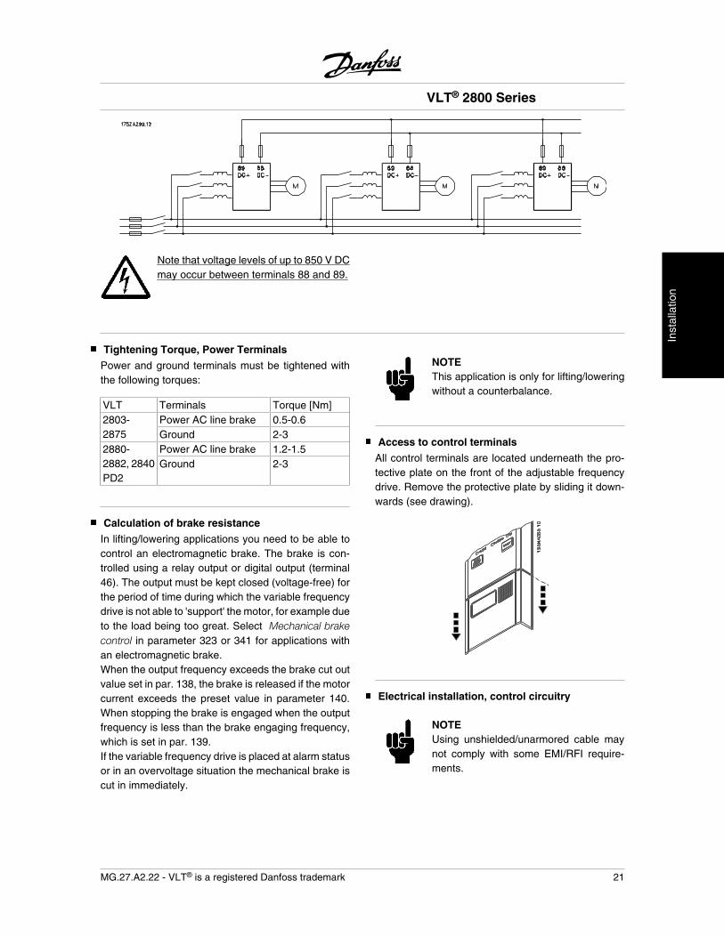
Note that voltage levels of up to 850 V DCmay occur between terminals 88 and 89.
Tightening Torque, Power Terminals
Power and ground terminals must be tightened withthe following torques:
VLT Terminals Torque [Nm]2803-2875
Power AC line brake 0.5-0.6Ground 2-3
2880-2882, 2840PD2
Power AC line brake 1.2-1.5Ground 2-3
Calculation of brake resistance
In lifting/lowering applications you need to be able tocontrol an electromagnetic brake. The brake is con-trolled using a relay output or digital output (terminal46). The output must be kept closed (voltage-free) forthe period of time during which the variable frequencydrive is not able to 'support' the motor, for example dueto the load being too great. Select Mechanical brakecontrol in parameter 323 or 341 for applications withan electromagnetic brake.When the output frequency exceeds the brake cut outvalue set in par. 138, the brake is released if the motorcurrent exceeds the preset value in parameter 140.When stopping the brake is engaged when the outputfrequency is less than the brake engaging frequency,which is set in par. 139.If the variable frequency drive is placed at alarm statusor in an overvoltage situation the mechanical brake iscut in immediately.
NOTEThis application is only for lifting/loweringwithout a counterbalance.
Access to control terminals
All control terminals are located underneath the pro-tective plate on the front of the adjustable frequencydrive. Remove the protective plate by sliding it down-wards (see drawing).
Electrical installation, control circuitry
NOTEUsing unshielded/unarmored cable maynot comply with some EMI/RFI require-ments.
VLT® 2800 Series
MG.27.A2.22 - VLT® is a registered Danfoss trademark 21
Inst
alla
tion
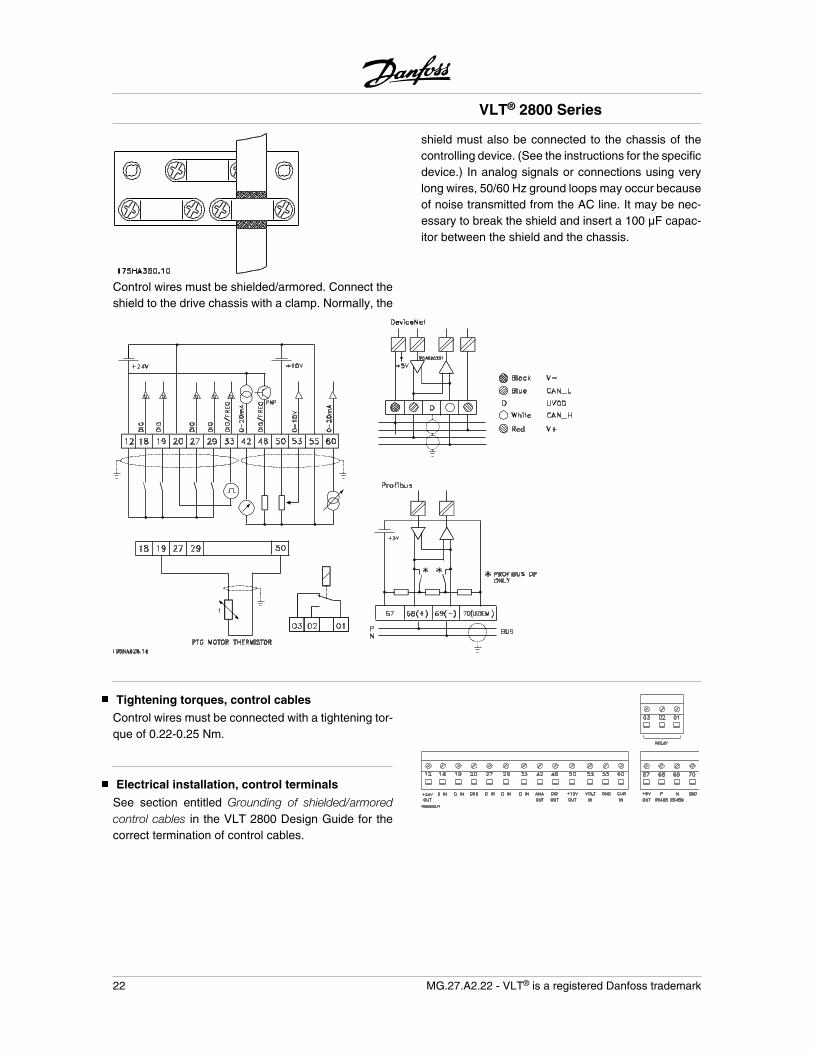
Control wires must be shielded/armored. Connect theshield to the drive chassis with a clamp. Normally, the
shield must also be connected to the chassis of thecontrolling device. (See the instructions for the specificdevice.) In analog signals or connections using verylong wires, 50/60 Hz ground loops may occur becauseof noise transmitted from the AC line. It may be nec-essary to break the shield and insert a 100 F capac-itor between the shield and the chassis.
Tightening torques, control cables
Control wires must be connected with a tightening tor-que of 0.22-0.25 Nm.
Electrical installation, control terminals
See section entitled Grounding of shielded/armoredcontrol cables in the VLT 2800 Design Guide for thecorrect termination of control cables.
VLT® 2800 Series
22 MG.27.A2.22 - VLT® is a registered Danfoss trademark
No. Function01-03 Relay outputs 01-03 can be used for
indicating status and alarms/warnings.12 24 V DC voltage supply.18-33 Digital inputs.20, 55 Common frame for input
and output terminals.42 Analog output for displaying frequency,
reference, current or torque.461 Digital output for displaying status,
warnings or alarms, as well asfrequency output.
50 +10 V DC supplyvoltage for potentiometer or thermistor.
53 Analogue voltage input 0-10 V DC.60 Analogue current input 0/4 - 20 mA.671 + 5 V DC supply voltage
to Profibus.68, 691 RS-485, Serial communication.701 Frame for terminals 67, 68 and 69.
Normally, this terminal is not to be used.
1. The terminals are not valid for DeviceNet/CANopen.See also the DeviceNet manual, MG.90.BX.YY for fur-ther details.
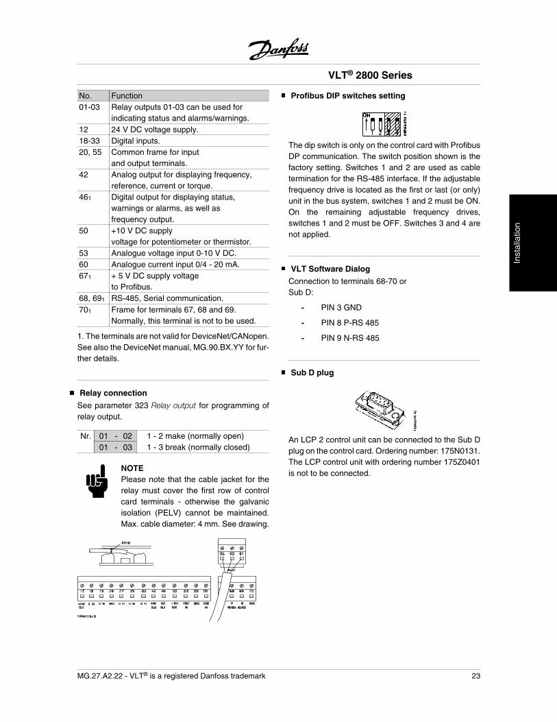
Relay connection
See parameter 323 Relay output for programming ofrelay output.
Nr. 01 - 02 1 - 2 make (normally open)01 - 03 1 - 3 break (normally closed)
NOTEPlease note that the cable jacket for therelay must cover the first row of controlcard terminals - otherwise the galvanicisolation (PELV) cannot be maintained.Max. cable diameter: 4 mm. See drawing.
Profibus DIP switches setting
The dip switch is only on the control card with ProfibusDP communication. The switch position shown is thefactory setting. Switches 1 and 2 are used as cabletermination for the RS-485 interface. If the adjustablefrequency drive is located as the first or last (or only)unit in the bus system, switches 1 and 2 must be ON.On the remaining adjustable frequency drives,switches 1 and 2 must be OFF. Switches 3 and 4 arenot applied.
VLT Software Dialog
Connection to terminals 68-70 orSub D:
- PIN 3 GND
- PIN 8 P-RS 485
- PIN 9 N-RS 485
Sub D plug
An LCP 2 control unit can be connected to the Sub Dplug on the control card. Ordering number: 175N0131.The LCP control unit with ordering number 175Z0401is not to be connected.
VLT® 2800 Series
MG.27.A2.22 - VLT® is a registered Danfoss trademark 23
Inst
alla
tion
Connection examples
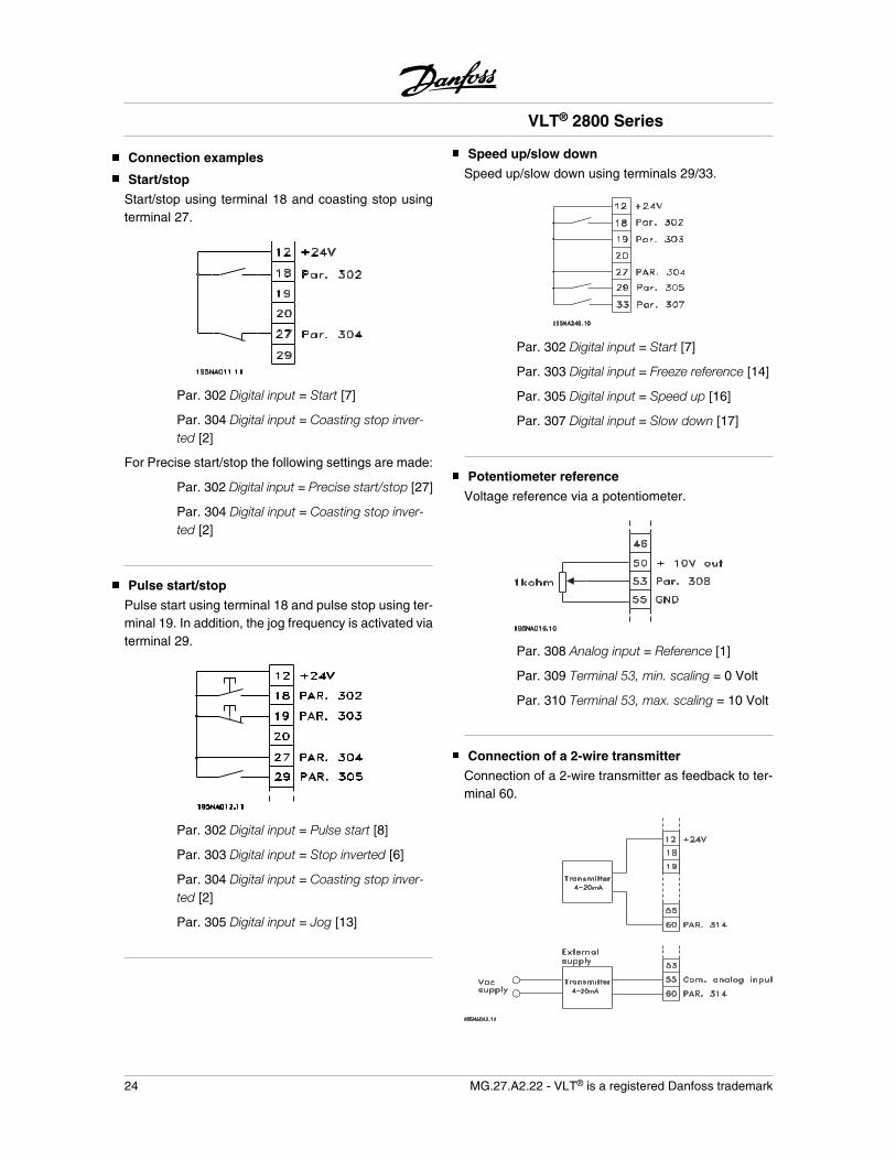
Start/stop
Start/stop using terminal 18 and coasting stop usingterminal 27.
Par. 302 Digital input = Start [7]
Par. 304 Digital input = Coasting stop inver-ted [2]
For Precise start/stop the following settings are made:
Par. 302 Digital input = Precise start/stop [27]
Par. 304 Digital input = Coasting stop inver-ted [2]
Pulse start/stop
Pulse start using terminal 18 and pulse stop using ter-minal 19. In addition, the jog frequency is activated viaterminal 29.
Par. 302 Digital input = Pulse start [8]
Par. 303 Digital input = Stop inverted [6]
Par. 304 Digital input = Coasting stop inver-ted [2]
Par. 305 Digital input = Jog [13]
Speed up/slow down
Speed up/slow down using terminals 29/33.
Par. 302 Digital input = Start [7]
Par. 303 Digital input = Freeze reference [14]
Par. 305 Digital input = Speed up [16]
Par. 307 Digital input = Slow down [17]
Potentiometer reference
Voltage reference via a potentiometer.
Par. 308 Analog input = Reference [1]
Par. 309 Terminal 53, min. scaling = 0 Volt
Par. 310 Terminal 53, max. scaling = 10 Volt
Connection of a 2-wire transmitter
Connection of a 2-wire transmitter as feedback to ter-minal 60.
VLT® 2800 Series
24 MG.27.A2.22 - VLT® is a registered Danfoss trademark

Par. 314 Analog input = Feedback [2]
Par. 315 Terminal 60, min. scaling = 4 mA
Par. 316 Terminal 60, max. scaling = 20 mA
VLT® 2800 Series
MG.27.A2.22 - VLT® is a registered Danfoss trademark 25
Inst
alla
tion
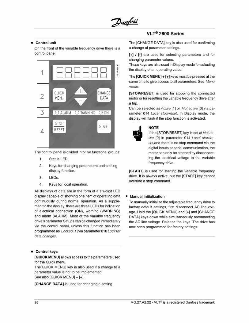
Control unit
On the front of the variable frequency drive there is acontrol panel.
The control panel is divided into five functional groups:
1. Status LED
2. Keys for changing parameters and shiftingdisplay function.
3. LEDs.
4. Keys for local operation.
All displays of data are in the form of a six-digit LEDdisplay capable of showing one item of operating datacontinuously during normal operation. As a supple-ment to the display, there are three LEDs for indicationof electrical connection (ON), warning (WARNING)and alarm (ALARM). Most of the variable frequencydrive's parameter Setups can be changed immediatelyvia the control panel, unless this function has beenprogrammed as Locked [1] via parameter 018 Lock fordata changes.
Control keys
[QUICK MENU] allows access to the parameters usedfor the Quick menu.The[QUICK MENU] key is also used if a change to aparameter value is not to be implemented.See also [QUICK MENU] + [+].
[CHANGE DATA] is used for changing a setting.
The [CHANGE DATA] key is also used for confirminga change of parameter settings.
[+] / [-] are used for selecting parameters and forchanging parameter values.These keys are also used in Display mode for selectingthe display of an operating value.
The [QUICK MENU] + [+] keys must be pressed at thesame time to give access to all parameters. See Menumode.
[STOP/RESET] is used for stopping the connectedmotor or for resetting the variable frequency drive aftera trip.Can be selected as Active [1] or Not active [0] via pa-rameter 014 Local stop/reset. In Display mode, thedisplay will flash if the stop function is activated.
NOTEIf the [STOP/RESET] key is set at Not ac-tive [0] in parameter 014 Local stop/re-set,and there is no stop command via thedigital inputs or serial communication, themotor can only be stopped by disconnect-ing the electrical voltage to the variablefrequency drive.
[START] is used for starting the variable frequencydrive. It is always active, but the [START] key cannotoverride a stop command.
Manual initialization
To manually initialize the adjustable frequency drive tofactory default settings, first disconnect AC line volt-age. Hold the [QUICK MENU] and [+] and [CHANGEDATA] keys down while simultaneously reconnectingthe AC line voltage. Release the keys. The drive hasnow been programmed for factory settings.
VLT® 2800 Series
26 MG.27.A2.22 - VLT® is a registered Danfoss trademark
Display readout states
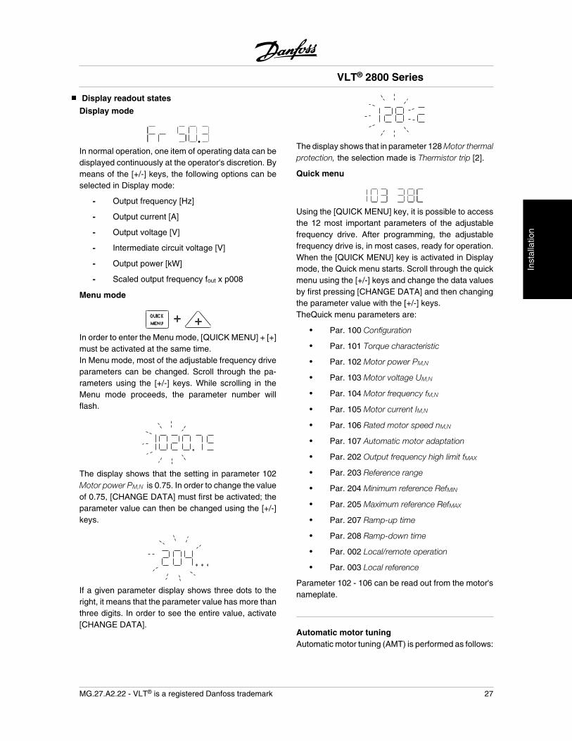
Display mode
In normal operation, one item of operating data can bedisplayed continuously at the operator's discretion. Bymeans of the [+/-] keys, the following options can beselected in Display mode:
- Output frequency [Hz]
- Output current [A]
- Output voltage [V]
- Intermediate circuit voltage [V]
- Output power [kW]
- Scaled output frequency fout x p008
Menu mode
In order to enter the Menu mode, [QUICK MENU] + [+]must be activated at the same time.In Menu mode, most of the adjustable frequency driveparameters can be changed. Scroll through the pa-rameters using the [+/-] keys. While scrolling in theMenu mode proceeds, the parameter number willflash.
The display shows that the setting in parameter 102Motor power PM,N is 0.75. In order to change the valueof 0.75, [CHANGE DATA] must first be activated; theparameter value can then be changed using the [+/-]keys.
If a given parameter display shows three dots to theright, it means that the parameter value has more thanthree digits. In order to see the entire value, activate[CHANGE DATA].
The display shows that in parameter 128 Motor thermalprotection, the selection made is Thermistor trip [2].
Quick menu
Using the [QUICK MENU] key, it is possible to accessthe 12 most important parameters of the adjustablefrequency drive. After programming, the adjustablefrequency drive is, in most cases, ready for operation.When the [QUICK MENU] key is activated in Displaymode, the Quick menu starts. Scroll through the quickmenu using the [+/-] keys and change the data valuesby first pressing [CHANGE DATA] and then changingthe parameter value with the [+/-] keys.TheQuick menu parameters are:
• Par. 100 Configuration
• Par. 101 Torque characteristic
• Par. 102 Motor power PM,N
• Par. 103 Motor voltage UM,N
• Par. 104 Motor frequency fM,N
• Par. 105 Motor current IM,N
• Par. 106 Rated motor speed nM,N
• Par. 107 Automatic motor adaptation
• Par. 202 Output frequency high limit fMAX
• Par. 203 Reference range
• Par. 204 Minimum reference RefMIN
• Par. 205 Maximum reference RefMAX
• Par. 207 Ramp-up time
• Par. 208 Ramp-down time
• Par. 002 Local/remote operation
• Par. 003 Local reference
Parameter 102 - 106 can be read out from the motor'snameplate.
Automatic motor tuningAutomatic motor tuning (AMT) is performed as follows:
VLT® 2800 Series
MG.27.A2.22 - VLT® is a registered Danfoss trademark 27
Inst
alla
tion
1. In parameter 107 Automatic motor tuning, se-lect data value [2]. "107" will now flash, and"2" will not flash.
2. AMT is activated by pressing start. "107" willnow flash and dashes will move from left toright in the data value field.
3. When "107" appears once more with the datavalue [0], AMT is complete. Press [STOP/RESET] to save the motor data.
4. "107" will then continue to flash with the datavalue [0]. You can now proceed.
NOTEVLT 2880-2882 do not have AMT func-tion.
VLT® 2800 Series
28 MG.27.A2.22 - VLT® is a registered Danfoss trademark
Display readout
FrThe variable frequency drive shows the present outputfrequency in Hertz [Hz].
IoThe variable frequency drive shows the present outputcurrent in Amps [A].
UoThe variable frequency drive shows the present outputvoltage in Volt [V].
UdThe variable frequency drive shows the intermediatecircuit voltage in Volt [V].
PoThe variable frequency drive shows the calculated out-put in kilowatt [kW].
notrunThis message is shown if an attempt is made tochange a parameter value while the motor is running.Stop the motor to change the parameter value.
LCPThis message is shown if an LCP 2 control unit is fittedand the [QUICK MENU] or [CHANGE DATA] key isactivated. If an LCP 2 control unit is fitted you can onlychange parameters with that.
HaThe variable frequency drive shows the present Handmode reference frequency in Herz (Hz).
SCThe variable frequency drive shows scaled output fre-quency (the present output frequency x parameter008).
Hand Auto
During normal operation the adjustable frequencydrive is in auto mode, where the reference signal isgiven externally, analog or digital via the control ter-minals. However, in hand mode, it is possible to givethe reference signal locally via the control panel.
On the control terminals, the following control signalswill remain active when hand mode is activated:
• Hand Start (LCP2)
• Off Stop (LCP2)
• Auto Start (LCP2)
• Reset
• Coasting Stop Inverse
• Reset and Coasting Stop Inverse
• Quick Stop Inverse
• Stop Inverse
• Reversing
• DC Braking Inverse
• Set-up Select LSB
• Set-up Select MSB
• Thermistor
• Precise Stop Inverse
• Precise Stop/Start
• Jog
• Stop Command Via Serial Comm.
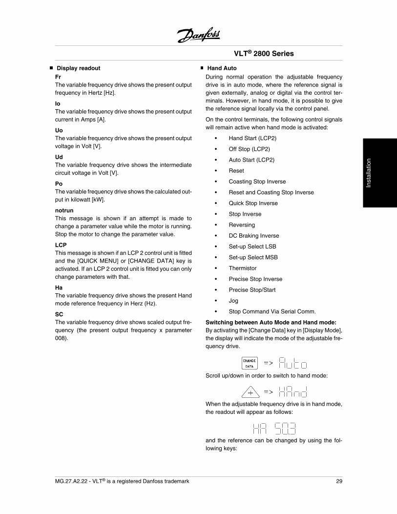
Switching between Auto Mode and Hand mode:By activating the [Change Data] key in [Display Mode],the display will indicate the mode of the adjustable fre-quency drive.
Scroll up/down in order to switch to hand mode:
When the adjustable frequency drive is in hand mode,the readout will appear as follows:
and the reference can be changed by using the fol-lowing keys:
VLT® 2800 Series
MG.27.A2.22 - VLT® is a registered Danfoss trademark 29
Inst
alla
tion
NOTEPlease note that parameter 020 may blockthe choice of mode.
Warnings/alarms
Warnings or alarms appear in the LED display as anumerical code [Err. xx]. A warning is displayed untilthe fault has been corrected, while an alarm will flashuntil the [STOP/RESET] key is pressed. The table inWarnings/alarms messages in this manual explains thevarious warnings and alarms, and whether a fault locksthe adjustable frequency drive. After a Trip lockedfault, cut off the AC line supply and correct the fault.Then reconnect the AC line supply and press the[STOP/RESET] key. The adjustable frequency drive isnow reset and ready. See Warnings/alarms messagesin this manual for more detail.
VLT® 2800 Series
30 MG.27.A2.22 - VLT® is a registered Danfoss trademark
Special conditions
Derating for ambient temperature
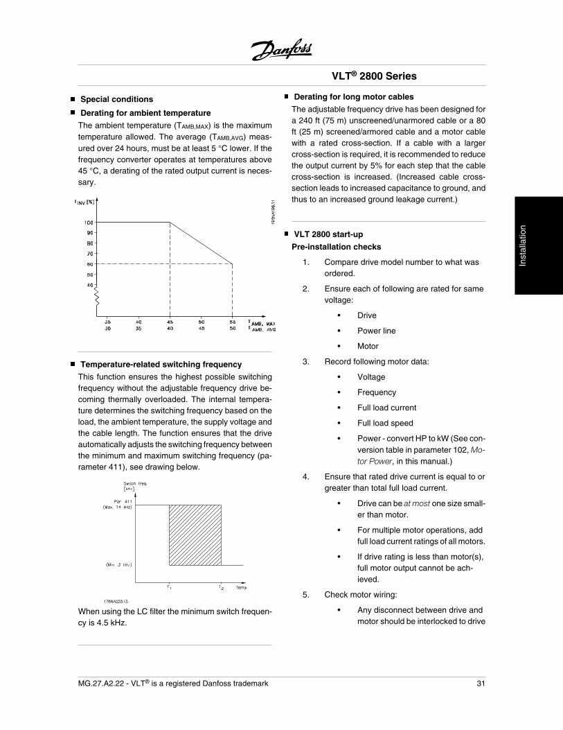
The ambient temperature (TAMB,MAX) is the maximumtemperature allowed. The average (TAMB,AVG) meas-ured over 24 hours, must be at least 5 °C lower. If thefrequency converter operates at temperatures above45 °C, a derating of the rated output current is neces-sary.
Temperature-related switching frequency
This function ensures the highest possible switchingfrequency without the adjustable frequency drive be-coming thermally overloaded. The internal tempera-ture determines the switching frequency based on theload, the ambient temperature, the supply voltage andthe cable length. The function ensures that the driveautomatically adjusts the switching frequency betweenthe minimum and maximum switching frequency (pa-rameter 411), see drawing below.
When using the LC filter the minimum switch frequen-cy is 4.5 kHz.
Derating for long motor cables
The adjustable frequency drive has been designed fora 240 ft (75 m) unscreened/unarmored cable or a 80ft (25 m) screened/armored cable and a motor cablewith a rated cross-section. If a cable with a largercross-section is required, it is recommended to reducethe output current by 5% for each step that the cablecross-section is increased. (Increased cable cross-section leads to increased capacitance to ground, andthus to an increased ground leakage current.)
VLT 2800 start-up
Pre-installation checks
1. Compare drive model number to what wasordered.
2. Ensure each of following are rated for samevoltage:
• Drive
• Power line
• Motor
3. Record following motor data:
• Voltage
• Frequency
• Full load current
• Full load speed
• Power - convert HP to kW (See con-version table in parameter 102, Mo-tor Power, in this manual.)
4. Ensure that rated drive current is equal to orgreater than total full load current.
• Drive can be at most one size small-er than motor.
• For multiple motor operations, addfull load current ratings of all motors.
• If drive rating is less than motor(s),full motor output cannot be ach-ieved.
5. Check motor wiring:
• Any disconnect between drive andmotor should be interlocked to drive
VLT® 2800 Series
MG.27.A2.22 - VLT® is a registered Danfoss trademark 31
Inst
alla
tion
safety interlock circuit to avoid un-wanted drive trips.
• No power factor correction capaci-tors can be connected betweendrive and motor.
• Two speed motors must be wiredpermanently for full speed.
• Y-start, -run motors must be wiredpermanently for run.
Installation checks
1. Input fusing in power supply for all drivesmust be provided.
2. Environmental concerns - for standardNEMA 1 drive:
• Clean air supply
• Dry air (5% to 85% relative humidity,non-condensing)
• 32°F (0°C) to 104°F (40°C) ambienttemperature operating range, or asrated
• 1000m (3,300 ft) maximum eleva-tion with no derating
• Keep any construction dirt out ofdrive.
3. Wiring
• Wire drive in accordance with in-structions and diagrams receivedwith drive.
• Separate conduits must be provi-ded to drive for input power, outputpower, and control wiring.
• Protect signal wires from noise.
• Ground each drive individually.
• Double check input and output pow-er wiring for correct location.
Setting up drive for motor startEnsure that all warnings provided in this manual havebeen adhered to. Apply power to the unit. Enter motornameplate data into drive through Quick Menu.
1. Parameter 102, MOTOR POWER (in kW)(See conversion table in parameter 102, Mo-tor Power, in this manual.)
2. Parameter 103, MOTOR VOLTAGE
3. Parameter 104, MOTOR FREQUENCY
4. Parameter 105, MOTOR CURRENT
5. Parameter 106, MOTOR SPEED
6. Parameter 107, select AUTOMATIC MOTORTUNING
Operational tests - HAND
1. Check motor rotation from drive. If incorrect,disconnect input power from drive and re-verse two leads between drive and motor.
2. Accelerate motor quickly to full speed andverify operation.
3. Decelerate motor quickly to stop and verifyoperation.
4. Operate motor over entire speed range whileclosely checking for resonance.
Operational tests - AUTO
1. Ensure that drive follows run/stop and safetyinterlock commands from system.
2. Ensure drive follows speed reference, orfeedback, from system.
VLT® 2800 Series
32 MG.27.A2.22 - VLT® is a registered Danfoss trademark
Operation & Display
001 Language
(language)
Value:
English (english) [0]
German (deutsch) [1]
French (francais) [2]
Danish (dansk) [3]
Spanish (espanol) [4]
Italian (italiano) [5]
Function:This parameter is used to choose the language to beshown in the display whenever the LCP control unit isconnected.
Description of choice:There is a choice of the languages shown. The factorysetting may vary.
002 Local/remote operation
(OPERATION SITE)
Value:
Remote operation (REMOTE) [0]
Local operation (LOCAL) [1]
Function:There is a choice of two different modes of operationof the adjustable frequency drive; Remote operation [0]or Local operation [1]. See also parameter 013 Localcontrol if Local operation [1] is selected.
Description of choice:If Remote operation [0] is selected, the adjustable fre-quency drive is controlled via:
1. the control terminals or via serial communi-cation.
2. the [START] key. This cannot, however,override stop commands transmitted via thedigital inputs or via serial communication.
3. the [STOP/RESET] and [JOG] keys, on thecondition that these are active.
If Local operation [1], is selected, the adjustable fre-quency drive is controlled via:
1. the [START] key. This cannot, however,override stop commands via the digital inputs(see parameter 013 Local control).
2. the [STOP/RESET] and [JOG] keys, on thecondition that these are active.
3. the [FWD/REV] key, on the condition that ishas been selected as active in parameter 016Local reversing, and that parameter 013 Localcontrol is set at Local control and open loop[1] or Local control as parameter 100 [3]. Pa-rameter 200 Output frequency range is setat Both directions.
4. parameter 003 Local reference where the ref-erence can be set using the [+] and [-] keys.
5. an external control command that can beconnected to the digital inputs (see parame-ter 013 Local control).
NOTEThe [JOG] and [FWD/REV] keys are lo-cated on the LCP control unit.
003 Local reference
(LOCAL REFERENCE)
Value:Par. 013 Local control must be set to [1]or [2]:0 - fMAX (par. 205) 50 Hz
Par. 013 Local control must be set to [3] or[4].RefMIN - Ref MAX (par. 204-205) 0,0
Function:In this parameter, the local reference can be set man-ually. The unit of the local reference depends on theconfiguration selected in parameter 100 Configura-tion.
Description of choice:In order to protect the local reference, parameter 002Local/remote operation must be set to Local opera-tion [1]. Local reference cannot be set via serial com-munication.
VLT® 2800 Series
= factory setting, () = display text, [] = value for use in communication via serial communication port
MG.27.A2.22 - VLT® is a registered Danfoss trademark 33
Pro
gram
min
g
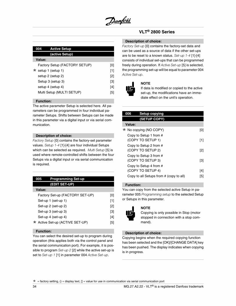
004 Active Setup
(active Setup)
Value:
Factory Setup (FACTORY SETUP) [0]
setup 1 (setup 1) [1]
setup 2 (setup 2) [2]
Setup 3 (setup 3) [3]
setup 4 (setup 4) [4]
Multi Setup (MULTI SETUP) [5]
Function:The active parameter Setup is selected here. All pa-rameters can be programmed in four individual pa-rameter Setups. Shifts between Setups can be madein this parameter via a digital input or via serial com-munication.
Description of choice:Factory Setup [0] contains the factory-set parametervalues. Setup 1-4 [1]-[4] are four individual Setupswhich can be selected as required. Multi Setup [5] isused where remote-controlled shifts between the fourSetups via a digital input or via serial communicationis required.
005 Programming Set-up
(EDIT SET-UP)
Value:
Factory Set-up (FACTORY SET-UP) [0]
Set-up 1 (set-up 1) [1]
Set-up 2 (set-up 2) [2]
Set-up 3 (set-up 3) [3]
Set-up 4 (set-up 4) [4]
Active Set-up (ACTIVE SET-UP) [5]
Function:You can select the desired set-up to program duringoperation (this applies both via the control panel andthe serial communication port). For example, it is pos-sible to program Set-up 2 [2] while the active set-up isset to Set-up 1 [1] in parameter 004 Active Set-up.
Description of choice:Factory Set-up [0] contains the factory-set data andcan be used as a source of data if the other set-upsare to be reset to a known status. Set-up 1-4 [1]-[4]consists of individual set-ups that can be programmedfreely during operation. If Active Set-up [5] is selected,the programming set-up will be equal to parameter 004Active Set-up.
NOTEIf data is modified or copied to the activeset-up, the modifications have an imme-diate effect on the unit's operation.
006 Setup copying
(SETUP COPY)
Value:
No copying (NO COPY) [0]
Copy to Setup 1 from #(COPY TO SETUP 1) [1]
Copy to Setup 2 from #(COPY TO SETUP 2) [2]
Copy to Setup 3 from #(COPY TO SETUP 3) [3]
Copy to Setup 4 from #(COPY TO SETUP 4) [4]
Copy to all Setups from # (copy to all) [5]
Function:You can copy from the selected active Setup in pa-rameter 005 Programming setup to the selected Setupor Setups in this parameter.
NOTECopying is only possible in Stop (motorstopped in connection with a stop com-mand).
Description of choice:Copying begins when the required copying functionhas been selected and the [OK]/[CHANGE DATA] keyhas been pushed. The display indicates when copyingis in progress.
VLT® 2800 Series
= factory setting, () = display text, [] = value for use in communication via serial communication port
34 MG.27.A2.22 - VLT® is a registered Danfoss trademark
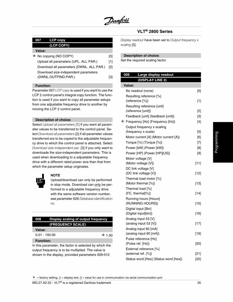
007 LCP copy
(LCP COPY)
Value:
No copying (NO COPY) [0]
Upload all parameters (UPL. ALL PAR.) [1]
Download all parameters (DWNL. ALL PAR.) [2]
Download size-independent parameters(DWNL.OUTPIND.PAR.) [3]
Function:Parameter 007 LCP copy is used if you want to use theLCP 2 control panel's integral copy function. The func-tion is used if you want to copy all parameter setupsfrom one adjustable frequency drive to another bymoving the LCP 2 control panel.
Description of choice:Select Upload all parameters [1] if you want all param-eter values to be transferred to the control panel. Se-lect Download all parameters [2] if all parameter valuestransferred are to be copied to the adjustable frequen-cy drive to which the control panel is attached. SelectDownload size-independent par. [3] if you only want todownloade the size-independent parameters. This isused when downloading to a adjustable frequencydrive with a different rated power size than that fromwhich the parameter setup originates.
NOTEUpload/download can only be performedin stop mode. Download can only be per-formed to a adjustable frequency drivewith the same software version number,see parameter 626 Database identificationno.
008 Display scaling of output frequency
(FREQUENCY SCALE)
Value:0.01 - 100.00 1.00
Function:In this parameter, the factor is selected by which theoutput frequency is to be multiplied. The value isshown in the display, provided parameters 009-012
Display readout have been set to Output frequency xscaling [5].
Description of choice:Set the required scaling factor.
009 Large display readout
(DISPLAY LINE 2)
Value:
No readout (none) [0]
Resulting reference [%](reference [%]) [1]
Resulting reference [unit](reference [unit]) [2]
Feedback [unit] (feedback [unit]) [3]
Frequency [Hz] (Frequency [Hz]) [4]
Output frequency x scaling(frequency x scale) [5]
Motor current [A] (Motor current [A]) [6]
Torque [%] (Torque [%]) [7]
Power [kW] (Power [kW]) [8]
Power [HP] (Power [HP][US]) [9]
Motor voltage [V](Motor voltage [V]) [11]
DC link voltage [V](DC link voltage [V]) [12]
Thermal load motor [%](Motor thermal [%]) [13]
Thermal load [%](FC. thermal[%]) [14]
Running hours [Hours](RUNNING HOURS]) [15]
Digital input [Bin](Digital input[bin]) [16]
Analog input 53 [V](analog input 53 [V]) [17]
Analog input 60 [mA](analog input 60 [mA]) [19]
Pulse reference [Hz](Pulse ref. [Hz]) [20]
External reference [%](external ref. [%]) [21]
Status word [Hex] (Status word [hex]) [22]
VLT® 2800 Series
= factory setting, () = display text, [] = value for use in communication via serial communication port
MG.27.A2.22 - VLT® is a registered Danfoss trademark 35
Pro
gram
min
g
Heatsink temperature [°C](Heatsink temp [°C]) [25]
Alarm word [Hex] (Alarm word [hex]) [26]
Control word [Hex] (Control word [Hex]) [27]
Warning word [Hex](warning word [Hex]) [28]
Extended status word [Hex](Ext. status [hex]) [29]
Communication option card warning(COMM OPT WARN [HEX]) [30]
Pulse count(PULSE COUNTER) [31]
Function:In this parameter you can select the data value thatyou wish to display in the LCP 2 control unit displayline 2 when the adjustable frequency drive is switchedon. The display will also be included in the scrollbar indisplay mode. In parameters 010-012 Display readoutyou can select a further three data values, which aredisplayed in display line 1.
Description of choice:No readout can only be selected in parameters010-012 Small display readout.
Resulting reference [%] gives, as a percentage, the re-sulting reference in the range from Minimum refer-ence, RefMIN to Maximum reference, RefMAX.
Reference [unit] gives the resulting reference with unitHz in Open loop. In Closed loop the reference unit isselected in parameter 416 Process units.
Feedback [unit] gives the resulting signal value usingthe unit/scaling selected in parameter 414 Minimumfeedback, FBLOW , 415 Maximum feedback, FBHIGH and416 Process units.
Frequency [Hz] gives the output frequency of the ad-justable frequency drive.
Output frequency x scaling [-] equals the present outputfrequency fM multiplied by the factor set in parameter008 Display scaling of output frequency .
Motor current [A] gives the phase current of the motormeasured as an effective value.
Torque [%] denotes the motor's present load in relationto the motor's rated torque.
Power [kW] gives the present power that the motor isabsorbing in kW.
Power [HP] gives the present power that the motor isabsorbing in HP.
Motor voltage[V] gives the voltage supplied to the mo-tor.
DC link voltage [V] gives the intermediate circuit voltageof the adjustable frequency drive.
Thermal load motor [%] gives the calculated/estimatedload on the motor. 100 % is the cut-out limit.
Thermal load [%] gives the calculated/estimated ther-mal load on the adjustable frequency drive. 100 % isthe cut-out limit.
Running hours [Hours] gives the number of hours thatthe motor has tun since the last reset in parameter 619Reset of running hours counter.
Digital input [Binary code] gives the signal status fromthe 5 digital inputs (18, 19, 27, 29 and 33). Terminal18 corresponds to the bit on the extreme left. `0' = nosignal, `1' = signal connected.
Analog input 53 [V] gives the voltage value of terminal53.
Analog input 60 [mA] gives the present value of termi-nal 60.
Pulse reference [Hz] gives the reference in Hz connec-ted to terminal 33.
External reference [%] gives the sum of external refer-ences as a percentage (sum of analogue/pulse/serialcommunication) in the range from Minimum reference,RefMIN to Maximum reference, RefMAX.
Status word [Hex] gives one or several status condi-tions in a Hex code. See Serial communication in theVLT 2800 Design Guide for further information.
Heatsink temp.[°C] gives the present heatsink temper-ature of the adjustable frequency drive. The cut-outlimit is 90-100°C, while cutting back in occurs at 70 ±5°C.
Alarm word [Hex] gives one or several alarms in hexcode. See Serial communication in the VLT 2800 De-sign Guide for further information.
Control word [Hex] gives the control word for the ad-justable frequency drive. See Serial communication inthe VLT 2800 Design Guide for further information.
VLT® 2800 Series
= factory setting, () = display text, [] = value for use in communication via serial communication port
36 MG.27.A2.22 - VLT® is a registered Danfoss trademark
Warning word [Hex] gives one or several warnings inhex code. See Serial communication in the VLT 2800Design Guide for further information.
Extended status word [Hex] gives one or several statusmodes in Hex code. See Serial communication in theVLT 2800 Design Guide for further information.
Communication option card warning [Hex] gives awarning word if there is a fault in the communicationbus. Only active if communication options are instal-led.If there are no communication options 0 Hex is dis-played.
Pulse count gives the number of pulses that the unithas registered.
010 Small display line 1.1
(DISPLAY LINE 1.1)
Value:See par. 009 Large displayreadout
Analog input 53[V] [17]
Function:In this parameter, the first of three data values can beselected that is to be displayed in the LCP control unitdisplay, line 1, position 1. This is a useful function, e.g.when setting the PID regulator, as it gives a view ofprocess reactions to reference changes. The displayreadout is activated by pushing the [DISPLAY STA-TUS] key.
Description of choice:See parameter 009 Large display readout.
011 Small display readout 1.2
(DISPLAY LINE 1.2)
Value:See parameter 009 Large displayreadout
Motor cur-rent [A][6]
Function:See the functional description given under parameter010 Small display readout.
Description of choice:See parameter 009 Large display readout.
012 Small display readout 1.3
(DISPLAY LINE 1.3)
Value:See parameter 009 Large displayreadout
Feedback[unit] [3]
Function:See the functional description given under parameter010 Small display readout.
Description of choice:See parameter 009 Large display readout.
013 Local control
(LOC CTRL/CONFIG.)
Value:
Local not active (DISABLE) [0]
Local control and open loop without slip com-pensation(LOC CTRL/OPEN LOOP) [1]
Remote-operated control and open loop with-out slip compensation(LOC+DIG CTRL) [2]
Local control as parameter 100(LOC CTRL/AS P100) [3]
Remote-operated control as parameter 100(LOC+DIG CTRL/AS P100) [4]
Function:This is where the required function is selected if, inparameter 002 Local/remote operation, Local opera-tion [1] has been chosen.
Description of choice:If Local not active [0] is selected, it is not possible toset a reference via parameter 003 Local reference.In order to enable a shift to Local not active [0], param-eter 002 Local/remote operation must be set to Remoteoperation [0].
Local control and open loop [1] is used if the motorspeed is to be set via parameter 003 Local reference.When this choice is made, parameter 100 Configura-tion automatically shifts to Speed regulation, openloop [0].
Remote-operated control and open loop [2] functionsin the same way as Local control and open loop [1];
VLT® 2800 Series
= factory setting, () = display text, [] = value for use in communication via serial communication port
MG.27.A2.22 - VLT® is a registered Danfoss trademark 37
Pro
gram
min
g
however, the adjustable frequency drive can also becontrolled via the digital inputs.
For selections [1-2] control is shifted to open loop, noslip compensation.
Local control as parameter 100 [3] is used when themotor speed is to be set via parameter 003 Local ref-erence, but without parameter 100 Configuration auto-matically shifting to Speed regulation, open loop [0].
Remote-operated control as parameter 100 [4] worksthe same way as Local control as parameter 100 [3];however, the adjustable frequency drive can also becontrolled via the digital inputs.
Shifting from Remote operation to Local operation inparameter 002 Local/remote operation, while this pa-rameter has been set to Remote-operated control andopen loop [1]: The present motor frequency and direc-tion of rotation will be maintained. If the present direc-tion of rotation does not respond to the reversing signal(negative reference), the reference will be set to 0.
Shifting from Local operation to Remote operation inparameter 002 Local/remote control, while this param-eter has been set to Remote-operated control and openloop [1]: The configuration selected in parameter 100Configuration will be active. The shift will be smooth.
Shifting from Remote control to Local control in param-eter 002 Local/remote operation, while this parameterhas been set to Remote-operated control as parameter100 [4]: the present reference will be maintained. If thereference signal is negative, the local reference will beset to 0.
Shifting from Local operation to Remote operation inparameter 002 Local/remote operation, while this pa-rameter has been set to Remote operation: The localreference will be replaced by the remote-operated ref-erence signal.
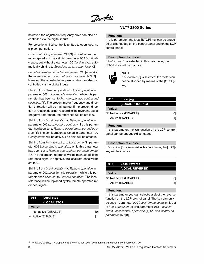
014 Local stop
(LOCAL STOP)
Value:
Not active (DISABLE) [0]
Active (ENABLE) [1]
Function:In this parameter, the local [STOP]-key can be engag-ed or disengaged on the control panel and on the LCPcontrol panel.
Description of choice:If Not active [0] is selected in this parameter, the[STOP]-key will be inactive.
NOTEIf Not active [0] is selected, the motor can-not be stopped by means of the [STOP]-key.
015 Local jog
(LOCAL JOGGING)
Value:
Not active (DISABLE) [0]
Active (ENABLE) [1]
Function:In this parameter, the jog function on the LCP controlpanel can be engaged/disengaged.
Description of choice:If Not active [0] is selected in this parameter, the [JOG]-key will be inactive.
016 Local reverse
(LOCAL REVERSE)
Value:
Not active (DISABLE) [0]
Active (ENABLE) [1]
Function:In this parameter you can select/deselect the reversefunction on the LCP control panel. The key can onlybe used if parameter 002 Local/remote operation is setto Local operation [1] and parameter 013 Localcon-trol to Local control, open loop [1] or Local control asparameter 100 [3].
VLT® 2800 Series
= factory setting, () = display text, [] = value for use in communication via serial communication port
38 MG.27.A2.22 - VLT® is a registered Danfoss trademark
Description of choice:If Disable [0] is selected in this parameter, the [FWD/REV] key will be disabled. See also parameter 200Output frequency range.
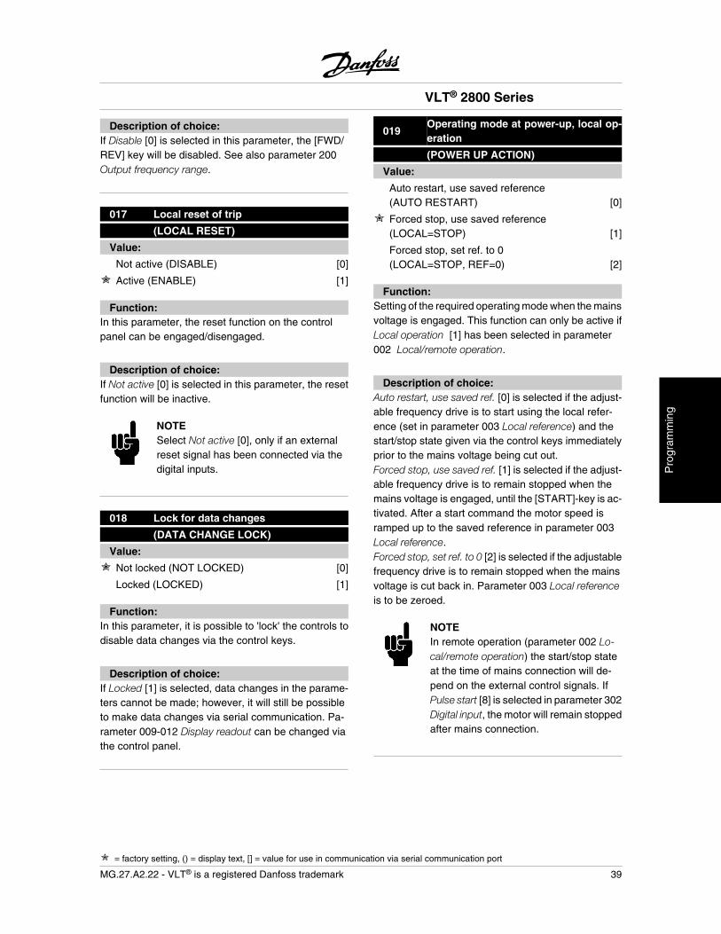
017 Local reset of trip
(LOCAL RESET)
Value:
Not active (DISABLE) [0]
Active (ENABLE) [1]
Function:In this parameter, the reset function on the controlpanel can be engaged/disengaged.
Description of choice:If Not active [0] is selected in this parameter, the resetfunction will be inactive.
NOTESelect Not active [0], only if an externalreset signal has been connected via thedigital inputs.
018 Lock for data changes
(DATA CHANGE LOCK)
Value:
Not locked (NOT LOCKED) [0]
Locked (LOCKED) [1]
Function:In this parameter, it is possible to 'lock' the controls todisable data changes via the control keys.
Description of choice:If Locked [1] is selected, data changes in the parame-ters cannot be made; however, it will still be possibleto make data changes via serial communication. Pa-rameter 009-012 Display readout can be changed viathe control panel.
019Operating mode at power-up, local op-eration
(POWER UP ACTION)
Value:
Auto restart, use saved reference(AUTO RESTART) [0]
Forced stop, use saved reference(LOCAL=STOP) [1]
Forced stop, set ref. to 0(LOCAL=STOP, REF=0) [2]
Function:Setting of the required operating mode when the mainsvoltage is engaged. This function can only be active ifLocal operation [1] has been selected in parameter002 Local/remote operation.
Description of choice:Auto restart, use saved ref. [0] is selected if the adjust-able frequency drive is to start using the local refer-ence (set in parameter 003 Local reference) and thestart/stop state given via the control keys immediatelyprior to the mains voltage being cut out.Forced stop, use saved ref. [1] is selected if the adjust-able frequency drive is to remain stopped when themains voltage is engaged, until the [START]-key is ac-tivated. After a start command the motor speed isramped up to the saved reference in parameter 003Local reference.Forced stop, set ref. to 0 [2] is selected if the adjustablefrequency drive is to remain stopped when the mainsvoltage is cut back in. Parameter 003 Local referenceis to be zeroed.
NOTEIn remote operation (parameter 002 Lo-cal/remote operation) the start/stop stateat the time of mains connection will de-pend on the external control signals. IfPulse start [8] is selected in parameter 302Digital input, the motor will remain stoppedafter mains connection.
VLT® 2800 Series
= factory setting, () = display text, [] = value for use in communication via serial communication port
MG.27.A2.22 - VLT® is a registered Danfoss trademark 39
Pro
gram
min
g
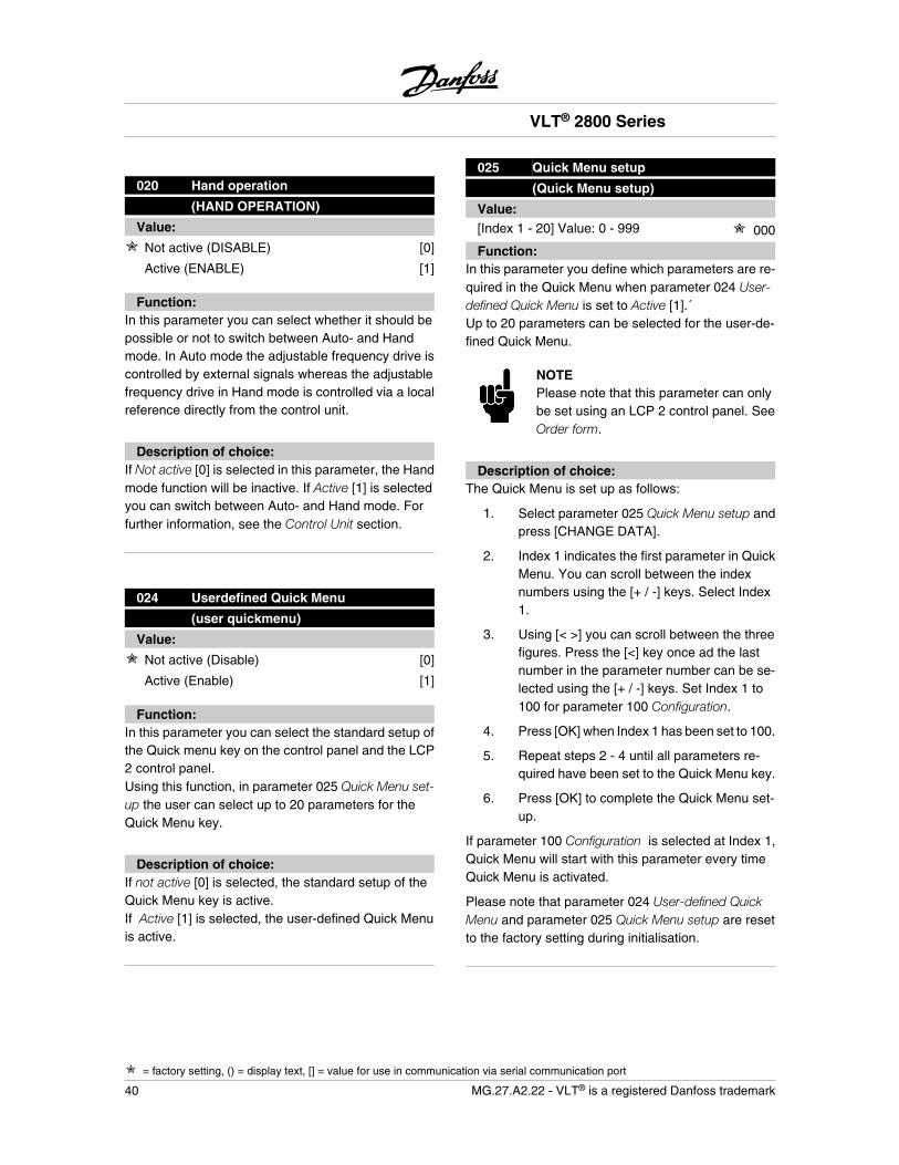
020 Hand operation
(HAND OPERATION)
Value:
Not active (DISABLE) [0]
Active (ENABLE) [1]
Function:In this parameter you can select whether it should bepossible or not to switch between Auto- and Handmode. In Auto mode the adjustable frequency drive iscontrolled by external signals whereas the adjustablefrequency drive in Hand mode is controlled via a localreference directly from the control unit.
Description of choice:If Not active [0] is selected in this parameter, the Handmode function will be inactive. If Active [1] is selectedyou can switch between Auto- and Hand mode. Forfurther information, see the Control Unit section.
024 Userdefined Quick Menu
(user quickmenu)
Value:
Not active (Disable) [0]
Active (Enable) [1]
Function:In this parameter you can select the standard setup ofthe Quick menu key on the control panel and the LCP2 control panel.Using this function, in parameter 025 Quick Menu set-up the user can select up to 20 parameters for theQuick Menu key.
Description of choice:If not active [0] is selected, the standard setup of theQuick Menu key is active.If Active [1] is selected, the user-defined Quick Menuis active.
025 Quick Menu setup
(Quick Menu setup)
Value:[Index 1 - 20] Value: 0 - 999 000
Function:In this parameter you define which parameters are re-quired in the Quick Menu when parameter 024 User-defined Quick Menu is set to Active [1].´Up to 20 parameters can be selected for the user-de-fined Quick Menu.
NOTEPlease note that this parameter can onlybe set using an LCP 2 control panel. SeeOrder form.
Description of choice:The Quick Menu is set up as follows:
1. Select parameter 025 Quick Menu setup andpress [CHANGE DATA].
2. Index 1 indicates the first parameter in QuickMenu. You can scroll between the indexnumbers using the [+ / -] keys. Select Index1.
3. Using [< >] you can scroll between the threefigures. Press the [<] key once ad the lastnumber in the parameter number can be se-lected using the [+ / -] keys. Set Index 1 to100 for parameter 100 Configuration.
4. Press [OK] when Index 1 has been set to 100.
5. Repeat steps 2 - 4 until all parameters re-quired have been set to the Quick Menu key.
6. Press [OK] to complete the Quick Menu set-up.
If parameter 100 Configuration is selected at Index 1,Quick Menu will start with this parameter every timeQuick Menu is activated.
Please note that parameter 024 User-defined QuickMenu and parameter 025 Quick Menu setup are resetto the factory setting during initialisation.
VLT® 2800 Series
= factory setting, () = display text, [] = value for use in communication via serial communication port
40 MG.27.A2.22 - VLT® is a registered Danfoss trademark
Load and Motor
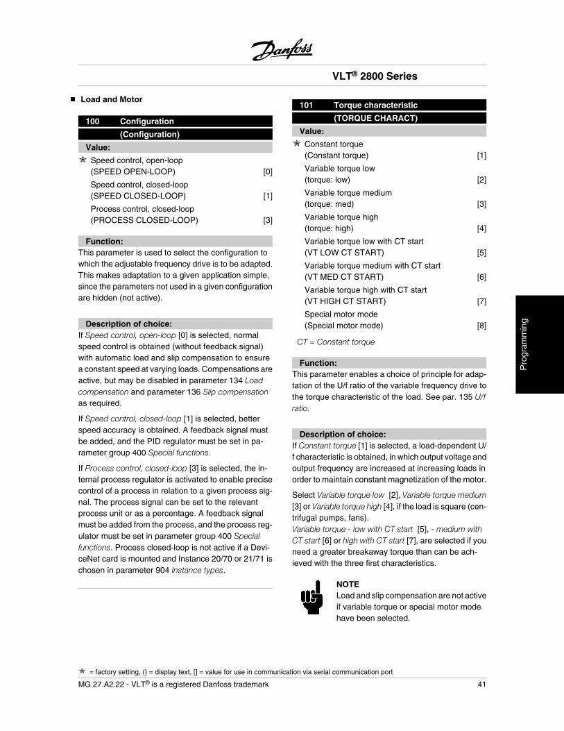
100 Configuration
(Configuration)
Value:
Speed control, open-loop(SPEED OPEN-LOOP) [0]
Speed control, closed-loop(SPEED CLOSED-LOOP) [1]
Process control, closed-loop(PROCESS CLOSED-LOOP) [3]
Function:This parameter is used to select the configuration towhich the adjustable frequency drive is to be adapted.This makes adaptation to a given application simple,since the parameters not used in a given configurationare hidden (not active).
Description of choice:If Speed control, open-loop [0] is selected, normalspeed control is obtained (without feedback signal)with automatic load and slip compensation to ensurea constant speed at varying loads. Compensations areactive, but may be disabled in parameter 134 Loadcompensation and parameter 136 Slip compensationas required.
If Speed control, closed-loop [1] is selected, betterspeed accuracy is obtained. A feedback signal mustbe added, and the PID regulator must be set in pa-rameter group 400 Special functions.
If Process control, closed-loop [3] is selected, the in-ternal process regulator is activated to enable precisecontrol of a process in relation to a given process sig-nal. The process signal can be set to the relevantprocess unit or as a percentage. A feedback signalmust be added from the process, and the process reg-ulator must be set in parameter group 400 Specialfunctions. Process closed-loop is not active if a Devi-ceNet card is mounted and Instance 20/70 or 21/71 ischosen in parameter 904 Instance types.
101 Torque characteristic
(TORQUE CHARACT)
Value:
Constant torque(Constant torque) [1]
Variable torque low(torque: low) [2]
Variable torque medium(torque: med) [3]
Variable torque high(torque: high) [4]
Variable torque low with CT start(VT LOW CT START) [5]
Variable torque medium with CT start(VT MED CT START) [6]
Variable torque high with CT start(VT HIGH CT START) [7]
Special motor mode(Special motor mode) [8]
CT = Constant torque
Function:This parameter enables a choice of principle for adap-tation of the U/f ratio of the variable frequency drive tothe torque characteristic of the load. See par. 135 U/fratio.
Description of choice:If Constant torque [1] is selected, a load-dependent U/f characteristic is obtained, in which output voltage andoutput frequency are increased at increasing loads inorder to maintain constant magnetization of the motor.
Select Variable torque low [2], Variable torque medium[3] or Variable torque high [4], if the load is square (cen-trifugal pumps, fans).Variable torque - low with CT start [5], - medium withCT start [6] or high with CT start [7], are selected if youneed a greater breakaway torque than can be ach-ieved with the three first characteristics.
NOTELoad and slip compensation are not activeif variable torque or special motor modehave been selected.
VLT® 2800 Series
= factory setting, () = display text, [] = value for use in communication via serial communication port
MG.27.A2.22 - VLT® is a registered Danfoss trademark 41
Pro
gram
min
g
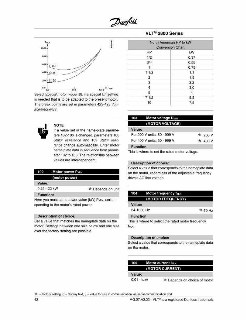
Select Special motor mode [8], if a special U/f settingis needed that is to be adapted to the present motor.The break points are set in parameters 423-428 Volt-age/frequency .
NOTEIf a value set in the name-plate parame-ters 102-106 is changed, parameters 108Stator resistance and 109 Stator reac-tance change automatically. Enter motorname plate data in sequence from param-eter 102 to 106. The relationship betweenvalues are interdependent.
102 Motor power PM,N
(motor power)
Value:0.25 - 22 kW Depends on unit
Function:Here you must set a power value [kW] PM,N, corre-sponding to the motor's rated power.
Description of choice:Set a value that matches the nameplate data on themotor. Settings between one size below and one sizeover the factory setting are possible.
North American HP to kWConversion Chart
HP kW1/2 0.373/4 0.551 0.75
1 1/2 1.12 1.53 2.24 3.05 4
7 1/2 5.510 7.5
103 Motor voltage UM,N
(MOTOR VOLTAGE)
Value:For 200 V units: 50 - 999 V 230 V
For 400 V units: 50 - 999 V 400 V
Function:This is where to set the rated motor voltage.
Description of choice:Select a value that corresponds to the nameplate dataon the motor, regardless of the adjustable frequencydrive's AC line voltage.
104 Motor frequency fM,N
(MOTOR FREQUENCY)
Value:24-1000 Hz 50 Hz
Function:This is where to select the rated motor frequencyfM,N.
Description of choice:Select a value that corresponds to the nameplate dataon the motor.
105 Motor current IM,N
(MOTOR CURRENT)
Value:0,01 - IMAX Depends on choice of motor
VLT® 2800 Series
= factory setting, () = display text, [] = value for use in communication via serial communication port
42 MG.27.A2.22 - VLT® is a registered Danfoss trademark
Function:The nominal, rated current of the motor IM,N forms partof the variable frequency drive calculation of featuressuch as torque and motor thermal protection.
Description of choice:Set a value that corresponds to the nameplate data onthe motor. Set the motor current IM,N taking into ac-count whether the motor is star-connected Y or delta-connected .
106 Rated motor speed
(MOTOR NOM. SPEED)
Value:100 - fM,N x 60(max. 60000rpm)
Depends on parameter 104 Mo-tor frequency, fM,N
Function:This is where to set the value that corresponds to therated motor speed nM,N that can be seen from thenameplate data.
Description of choice:Select a value that corresponds to the nameplate dataon the motor.
NOTEThe max. value equals fM,N x 60. fM,N to beset in parameter 104 Motor frequency,fM,N .
107 Automatic motor tuning, AMT
(auto motor tun.)
Value:
Optimisation off (AMT off) [0]
Optimisation on (AMT start) [2]
Function:
NOTEAMT is not possible on VLT 2880-82.
- For AMT to define the motor parameters ac-ccurately, the correct nameplate data for themotor connected to the adjustable frequencydrive must be keyed into parameters 102 to106.
- Alarms will appear in the display if faults ariseduring tuning of the motor. See Warnings/alarms messages in this manual.
- As a rule, the AMT function can measure theRS values for motors that are 1-2 sizes largeror smaller than the adjustable frequencydrive’s nominal size.
- If you wish to interrupt automatic motor tun-ing, press the [STOP/RESET] key.
NOTEAMT may not be performed on motorsconnected in parallel, nor may setupchanges be made while AMT is running.
See Automatic motor tuning in this manual for the AMTprocedure.
Description of choice:Select Optimization on [2] as part of the AMT procedureif you want the adjustable frequency drive to performautomatic motor tuning.
108 Stator resistance RS
(STATOR RESISTAN)
Value:0.000 - X.XXX Depends on choice of motor
Function:After setting of parameters 102-106 Nameplate data, anumber of adjustments of various parameters is car-ried out automatically, including stator resistance RS.A manually entered RS must apply to a cold motor. Theshaft performance can be improved by fine-tuning RS
and XS, see procedure below.
NOTEParameters 108 Stator resistance RS and109 Stator reactance XS are normally notto be changed if nameplate data has beenset.
VLT® 2800 Series
= factory setting, () = display text, [] = value for use in communication via serial communication port
MG.27.A2.22 - VLT® is a registered Danfoss trademark 43
Pro
gram
min
g
Description of choice:RS can be set as follows:
1. Use the factory settings of RS which the ad-justable frequency drive itself chooses on thebasis of the motor nameplate data.
2. The value is stated by the motor supplier.
3. The value is obtained through manual meas-urements: RS can be calculated by measur-ing the resistance RPHASE-PHASE between twophase terminals. Where RPHASE-PHASE is low-er than 1-2 Ohms (typical for motors > 7.5HP, 400 V), a special Ohm-meter should beused (Thomson-bridge or similar). RS = 0.5 xRPHASE-PHASE .
4. RS is set automatically when AMT has beencompleted. See parameter 107 Auto motortuning.
109 Stator reactance XS
(STATOR REACTANCE)
Value:0.00 - X,XX Depends on choice of motor
Function:After parameters 102-106 Nameplate data are set, anumber of parameters are adjusted automatically, in-cluding stator reactance XS. The shaft performancecan be improved by fine-tuning RS and XS; see proce-dure below.
Description of choice:XS can be set as follows:
1. The value is stated by the motor supplier.
2. The value is obtained through manual meas-urements; XS is obtained by connecting amotor to line power and measuring thephase-phase voltage U M and the idle current.
Xs =UM
3 × IXL2
XL: See parameter 142.3. Use the factory settings of XS, which the ad-
justable frequency drive itself chooses on thebasis of the motor nameplate data.
117 Resonance damping
(resonance damping)
Value:
OFF 100 [OFF 100]
Off [OFF]
Function:It is possible to optimize the resonance damping in CTmode. The grade of the influence is adjusted in thisparameter.The value may be set between 0% (OFF) and 100%.100% corresponds to 50% reduction of U/F ratio.Default value is OFF.
Internal settings (fixed):The resonance filter is active from 10% of nominalspeed and above.In this case 5Hz and above.Speed to go from 0 to nominal flux level: 500msSpeed to go from nominal to 0 flux level: 500 ms
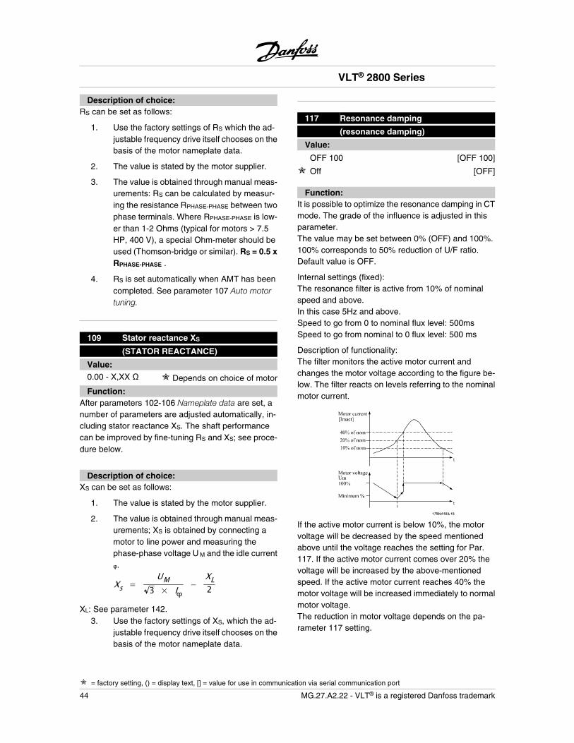
Description of functionality:The filter monitors the active motor current andchanges the motor voltage according to the figure be-low. The filter reacts on levels referring to the nominalmotor current.
If the active motor current is below 10%, the motorvoltage will be decreased by the speed mentionedabove until the voltage reaches the setting for Par.117. If the active motor current comes over 20% thevoltage will be increased by the above-mentionedspeed. If the active motor current reaches 40% themotor voltage will be increased immediately to normalmotor voltage.The reduction in motor voltage depends on the pa-rameter 117 setting.
VLT® 2800 Series
= factory setting, () = display text, [] = value for use in communication via serial communication port
44 MG.27.A2.22 - VLT® is a registered Danfoss trademark
Description of choice:Set the grade of Motor current [Imact] influence on theU/F ratio between 0% (OFF) and 100%. 100% corre-sponds to 50% reduction of U/F ratio. Default value isOFF.
119 High start torque
(High start torq.)
Value:0.0 - 0.5 sec. 0.0 sec.
Function:To ensure a high start torque approx. 1.8 x IINV. can bepermitted for max. 0.5 sec. The current is, however,limited by the variable frequency drive's (inverter's)safety limit. 0 sec. corresponds to no high start torque.
Description of choice:Set the necessary time for which a high start torque isrequired.
120 Start delay
(START DELAY)
Value:0.0 - 10.0 sec. 0.0 sec.
Function:This parameter enables a delay of the start-up timeafter the conditions for start have been fulfilled. Whenthe time has passed, the output frequency will start byramping up to the reference.
Description of choice:Set the necessary time before commencing to accel-erate.
121 Start function
(START FUNCTION)
Value:
DC hold during start delay time(DC HOLD/DELAY TIME) [0]
DC brake during start delay time(DC BRAKE/DELAY TIME) [1]
Coasting during start delay time [2]
(COAST/DELAY TIME)
Start frequency/voltage clockwise(CLOCKWISE OPERATION) [3]
Start frequency/voltage in reference direction(VERTICAL OPERATION) [4]
Function:This is where to choose the required mode during thestart delay time (parameter 120 Start delay time).
Description of choice:Select DC hold during start delay time [0] to energizethe motor with a DC hold voltage during the start delaytime. Set voltage in parameter 137 DC hold voltage.
Choose DC brake during start delay time [1] to energizethe motor with a DC brake voltage during the start de-lay time. Set voltage in parameter 132 DC brake volt-age.
Choose Coasting during start delay time [2] and themotor will not be controlled by the adjustable frequen-cy drive during the start delay time (inverter turned off).
Choose Start frequency/voltage clockwise [3] to obtainthe function described in parameter 130 Start frequen-cy and 131 Voltage at start during start delay time.Regardless of the value assumed by the referencesignal, the output frequency equals the setting in pa-rameter 130 Start frequency and the output voltage willcorrespond to the setting in parameter 131 Voltage atstart .This functionality is typically used in hoist applications.It is used in particular in applications in which a coneanchor motor is applied, where the direction of rotationis to start clockwise followed by the reference direc-tion.
Select Start frequency/voltage in reference direction [4]to obtain the function described in parameter 130 Startfrequency and 131 Voltage at start during the start de-lay time.The direction of rotation of the motor will always followin the reference direction. If the reference signalequals zero, the output frequency will equal 0 Hz, whilethe output voltage will correspond to the setting in pa-rameter 131 Voltage at start. If the reference signal isdifferent from zero, the output frequency will equal pa-rameter 130 Start frequency and the output voltage willequal parameter 131 Voltage at start. This functionalityis used typically for hoist applications with counter-
VLT® 2800 Series
= factory setting, () = display text, [] = value for use in communication via serial communication port
MG.27.A2.22 - VLT® is a registered Danfoss trademark 45
Pro
gram
min
g
weight. It is used in particular for applications in whicha cone anchor motor is applied. The cone anchor mo-tor can break away using parameter 130 Start frequen-cy and parameter 131 Voltage at start.
122 Function at stop
(FUNCTION AT STOP)
Value:
Coasting (COAST) [0]
DC hold (DC HOLD) [1]
Function:This is where to choose the function of the variablefrequency drive after the output frequency has becomelower than the value in parameter 123 The min. fre-quency for activation of function at stop or after a stopcommand and when the output frequency has beenramped down to 0 Hz.
Description of choice:Select Coasting [0] if the variable frequency drive is to'let go' of the motor (inverter turned off).
Select DC hold [1] if parameter 137 DC hold voltage isto be activated.
123Min. frequency for activation of func-tion at stop
(MIN.F.FUNC.STOP)
Value:0,1 - 10 Hz 0,1 Hz
Function:In this parameter, the output frequency is set at whichthe function selected in parameter 122 Function atstop is to be activated.
Description of choice:Set the required output frequency.
NOTEIf parameter 123 is set higher than param-eter 130, then the start delay function (pa-rameter 120 and 121) will be skipped.
NOTEIf parameter 123 is set too high, and DChold has been chosen in parameter 122,the output frequency will jump to the valuein parameter 123 without ramping up. Thismay cause an overcurrent warning /alarm.
126 DC brake time
(DC BRAKING TIME)
Value:0 - 60 sec. 10 sec
Function:In this parameter, the DC brake time is set at whichparameter 132 DC brake voltage is to be active.
Description of choice:Set the required time.
127 DC brake cut-in frequency
(DC BRAKE CUT-IN)
Value:0.0 (OFF) - par. 202Output frequency high limit, fMAX OFF
Function:In this parameter, the DC brake cut-in frequency is setat which the DC brake is to be activated in connectionwith a stop command.
Description of choice:Set the required frequency.
128 Thermal motor protection
(MOT.THERM PROTEC)
Value:
No protection (NO PROTECTION) [0]
Thermistor warning(THERMISTOR WARN) [1]
Thermistor trip (THERMISTOR TRIP) [2]
ETR warning 1 (ETR WARNING 1) [3]
ETR trip 1 (ETR TRIP 1) [4]
VLT® 2800 Series
= factory setting, () = display text, [] = value for use in communication via serial communication port
46 MG.27.A2.22 - VLT® is a registered Danfoss trademark

ETR warning 2 (ETR WARNING 2) [5]
ETR trip 2 (ETR TRIP 2) [6]
ETR warning 3 (ETR WARNING 3) [7]
ETR trip 3 (ETR TRIP 3) [8]
ETR warning 4 (ETR WARNING 4) [9]
ETR trip 4 (ETR TRIP 4) [10]
Function:The adjustable frequency drive can monitor the motortemperature in two different ways:
- Via a PTC thermistor that is mounted on themotor. The thermistor is connected betweenterminal 50 (+10V) and one of the digital inputterminals 18, 19, 27 or 29. See parameter300 Digital inputs.
- Thermal load calculation (ETR - ElectronicThermal Relay), based on present load andtime. This is compared with the rated motorcurrent IM,N and rated motor frequency f M,N.The calculations take into account the needfor lower loading at low speeds due to themotor's internal ventilation being reduced.
ETR functions 1-4 do not begin to calculate the loaduntil you switch to the Setup in which they have beenselected. This means that you can use the ETR func-tion even when changing between two or more motors.
Description of choice:Select No protection [0] if you do not want a warningor trip when a motor is overloaded.Select Thermistor warning [1] if you want a warningwhen the connected thermistor becomes too hot.Select Thermistor trip [2] if you want a trip when theconnected thermistor becomes too hot.
Select ETR warning 1-4 if you want a warning when themotor is overloaded according to the calculations. Youcan also program the adjustable frequency drive togive a warning signal via one of the digital outputs.Select ETR Trip 1-4 if you want a trip when the motoris overloaded according to the calculations.
NOTEThis function cannot protect the individualmotors in the case of motors linked in par-allel.
130 Start frequency
(Start frequency)
Value:0.0 - 10.0 Hz 0.0 Hz
Function:The start frequency is active for the time set in param-eter 120 Start delay, after a start command. The outputfrequency will 'jump' to the next preset frequency. Cer-tain motors, such as conical anchor motors, need anextra voltage/start frequency (boost) at start to disen-gage the mechanical brake. To achieve this parame-ters 130 Start frequency and 131 Initial voltage areused.
Description of choice:Set the required start frequency. It is a preconditionthat parameter 121 Start function, is set to Start fre-quency/voltage clockwise [3] or Start frequency voltagein reference direction [4] and that in parameter 120 Startdelay a time is set and a reference signal is present.
NOTEIf parameter 123 is set higher than param-eter 130, the start delay function (param-eter 120 and 121) will be skipped.
131 Initial voltage
(INITIAL VOLTAGE)
Value:0.0 - 200.0 V 0.0 V
VLT® 2800 Series
= factory setting, () = display text, [] = value for use in communication via serial communication port
MG.27.A2.22 - VLT® is a registered Danfoss trademark 47
Pro
gram
min
g
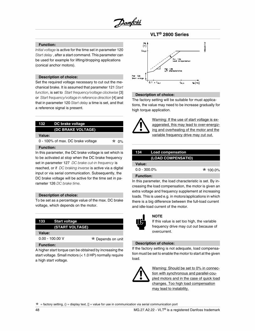
Function:Initial voltage is active for the time set in parameter 120Start delay , after a start command. This parameter canbe used for example for lifting/dropping applications(conical anchor motors).
Description of choice:Set the required voltage necessary to cut out the me-chanical brake. It is assumed that parameter 121 Startfunction, is set to Start frequency/voltage clockwise [3]or Start frequency/voltage in reference direction [4] andthat in parameter 120 Start delay a time is set, and thata reference signal is present.
132 DC brake voltage
(DC BRAKE VOLTAGE)
Value:0 - 100% of max. DC brake voltage 0%
Function:In this parameter, the DC brake voltage is set which isto be activated at stop when the DC brake frequencyset in parameter 127 DC brake cut-in frequency isreached, or if DC braking inverse is active via a digitalinput or via serial communication. Subsequently, theDC brake voltage will be active for the time set in pa-rameter 126 DC brake time.
Description of choice:To be set as a percentage value of the max. DC brakevoltage, which depends on the motor.
133 Start voltage
(START VOLTAGE)
Value:0.00 - 100.00 V Depends on unit
Function:A higher start torque can be obtained by increasing thestart voltage. Small motors (< 1.0 HP) normally requirea high start voltage.
Description of choice:The factory setting will be suitable for must applica-tions, the value may need to be increase gradually forhigh torque application.
Warning: If the use of start voltage is ex-aggerated, this may lead to over-energiz-ing and overheating of the motor and thevariable frequency drive may cut out.
134 Load compensation
(LOAD COMPENSATIO)
Value:0.0 - 300.0% 100.0%
Function:In this parameter, the load characteristic is set. By in-creasing the load compensation, the motor is given anextra voltage and frequency supplement at increasingloads. This is used e.g. in motors/applications in whichthere is a big difference between the full-load currentand idle-load current of the motor.
NOTEIf this value is set too high, the variablefrequency drive may cut out because ofovercurrent.
Description of choice:If the factory setting is not adequate, load compensa-tion must be set to enable the motor to start at the givenload.
Warning: Should be set to 0% in connec-tion with synchronous and parallel-cou-pled motors and in the case of quick loadchanges. Too high load compensationmay lead to instability.
VLT® 2800 Series
= factory setting, () = display text, [] = value for use in communication via serial communication port
48 MG.27.A2.22 - VLT® is a registered Danfoss trademark
135 U/f-ratio
(U/f RATIO)
Value:0.00 - 20.00 at Hz Depends on unit
Function:This parameter enables a linear shift in the ratio be-tween output voltage (V) and output frequency (f) toensure correct energizing of the motor and thus opti-mum dynamics, accuracy and efficiency. The V/f-ratioonly affects the voltage characteristic if Constant tor-que [1] has been selected in parameter 101 Torquecharacteristic .
Description of choice:Change the V/f-ratio only if it is not possible to set thecorrect motor data in parameters 102-109. The valueprogrammed in the factory settings is based on idleoperation.
136 Slip compensation
(SLIP COMP.)
Value:-500 - +500% of rated slip compensation 100%
Function:Slip compensation is calculated automatically, on thebasis of such data as the rated motor speed nM,N. Inthis parameter, the slip compensation can be fine-tuned, thereby compensating for tolerances on thevalue for nM,N. Slip compensation is only active if a se-lection has been made of Speedregulation, openloop [0] in parameter 100 Configuration and Constanttorque [1] in parameter 101 Torque characteristic.
Description of choice:Key in a % value.
137 DC hold voltage
(DC HOLD VOLTAGE)
Value:0 - 100% of max. DC hold voltage 0%
Function:This parameter is used to keep the motor (holding tor-que) at start/stop.
Description of choice:This parameter can only be used if a selection hasbeen made of DC hold in parameter 121 Start func-tion or 122 Function at stop . To be set as a percentagevalue of the max. DC hold voltage, which depends onthe choice of motor.
138 Brake cut out value
(Brake cut out)
Value:0.5 - 132.0/1000.0 Hz 3.0 Hz
Function:Select the frequency at which the external brake is re-leased, via the output defined in parameter 323 Relayoutput 1-3 or 341 Digital output, terminal 46.
Description of choice:Set the required frequency.
139 Brake cut in frequency
(Brake cut in)
Value:0.5 - 132.0/1000.0 Hz 3.0 Hz
Function:Select the frequency at which the external brake is ac-tivated; this takes place via the output defined in pa-rameter 323 Relay output 1-3 or 341 Digital outputterminal 46.
Description of choice:Set the required frequency.
140 Current, minimum value
(CURRENT MIN VAL)
Value:0 % - 100 % of inverter output current 0 %
VLT® 2800 Series
= factory setting, () = display text, [] = value for use in communication via serial communication port
MG.27.A2.22 - VLT® is a registered Danfoss trademark 49
Pro
gram
min
g
Function:This is where the user selects the minimum motor cur-rent running for the mechanical brake to be released.Current monitoring is only active from stop until thepoint when the brake is released.
Description of choice:This is an extra safety precaution, aimed at guaran-teeing that the load is not lost during start of a lifting/lowering operation.
142 Leakage reactance XL
(LEAK. REACTANCE)
Value:0.000 - XXX,XXX Depends on choice of mo-
torXL is the sum of rotor and sta-
tor leakage reactance.
Function:After setting of parameters 102-106 Nameplate data, anumber of adjustments of various parameters is madeautomatically, including the leakage reactance XL. Theshaft performance can be improved by fine-tuning theleakage reactance XL.
NOTEParameter 142 The leakage reactance XL
is normally not to be changed if the name-plate data has been set, parameters102-106.
Description of choice:XL can be set as follows:
1. The value is stated by the motor supplier.
2. Use the factory settings of XL, which the ad-justable frequency drive itself chooses on thebasis of the motor nameplate data.
143 Internal fan control
(fan control)
Value:
Automatic (automatic) [0]
Always switched on (always on) [1]
Always switched off (always off) [2]
Function:This parameter can be set so that the internal fan isautomatically switched on and off. You can also set theinternal fan to be permanently switched on or off.
Description of choice:If Automatic [0] is selected, the internal fan is switchedon or off depending on the ambient temperature andthe loading of the adjustable frequency drive.If Always switched on [1] or Always switched off [2] isselected, the internal fan will be permanently switchedon or off, respectively.
NOTEIf Always switched off [2] is selected incombination with high switch frequency,long motor cables or high output power,the adjustable frequency drive's life spanis reduced. This applies in particular to1.5, 2, 4 and 5 HP units.
144 Gain AC brake
(Gain AC brake)
Value:1.00 - 1.50 1.30
Function:This parameter is used to set the AC brake. Using par.144 it is possible to adjust the size of the generatortorque that can be applied to the motor without the in-termediate circuit voltage exceeding the warning level.
Description of choice:The value is increased if a greater possible brake tor-que is required. If 1.0 is selected, this corresponds tothe AC brake being inactive.
NOTEIf the value in par. 144 is increased, themotor current will simultaneously increasesignificantly when generator loads are ap-plied. The parameter should therefore on-ly be changed if it is guaranteed duringmeasurement that the motor current in all
VLT® 2800 Series
= factory setting, () = display text, [] = value for use in communication via serial communication port
50 MG.27.A2.22 - VLT® is a registered Danfoss trademark
operating situations will never exceed themaximum permitted current in the motor.Please note: that the current cannot beread out from the display.
146 Reset voltage vector
(RESET VECTOR)
Value:
*Off (OFF) [0]
Reset (RESET) [1]
Function:When the voltage vector is reset it is set to the samestarting point each time a new process commences.
Description of choice:Select reset (1) when running unique processes eachtime they arise. This will enable repetitive precisionwhen stopping to be improved. Select Off (0) for ex-ample for lifting/lowering operations or synchronousmotors. It is an advantage that the motor and the var-iable frequency drive are always synchronized.
VLT® 2800 Series
MG.27.A2.22 - VLT® is a registered Danfoss trademark 51
Pro
gram
min
g
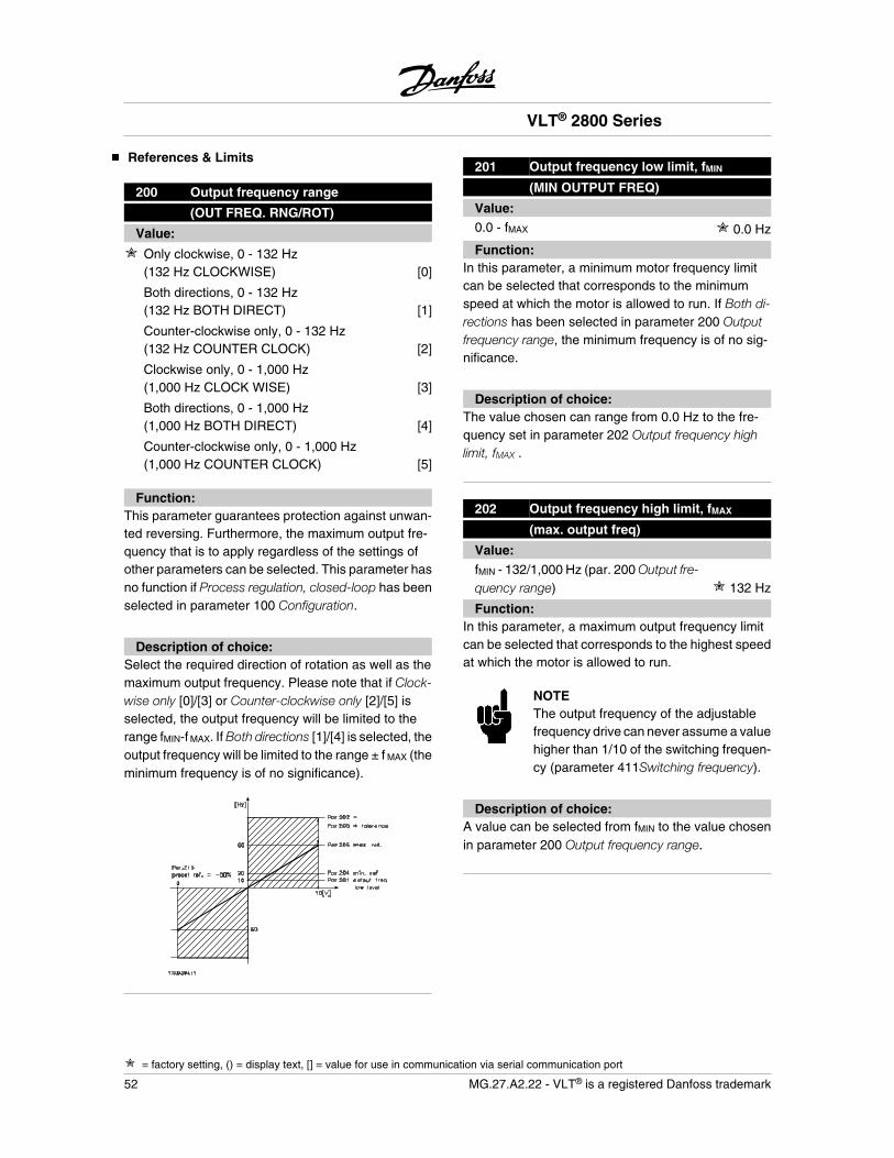
References & Limits
200 Output frequency range
(OUT FREQ. RNG/ROT)
Value:
Only clockwise, 0 - 132 Hz(132 Hz CLOCKWISE) [0]
Both directions, 0 - 132 Hz(132 Hz BOTH DIRECT) [1]
Counter-clockwise only, 0 - 132 Hz(132 Hz COUNTER CLOCK) [2]
Clockwise only, 0 - 1,000 Hz(1,000 Hz CLOCK WISE) [3]
Both directions, 0 - 1,000 Hz(1,000 Hz BOTH DIRECT) [4]
Counter-clockwise only, 0 - 1,000 Hz(1,000 Hz COUNTER CLOCK) [5]
Function:This parameter guarantees protection against unwan-ted reversing. Furthermore, the maximum output fre-quency that is to apply regardless of the settings ofother parameters can be selected. This parameter hasno function if Process regulation, closed-loop has beenselected in parameter 100 Configuration.
Description of choice:Select the required direction of rotation as well as themaximum output frequency. Please note that if Clock-wise only [0]/[3] or Counter-clockwise only [2]/[5] isselected, the output frequency will be limited to therange fMIN-f MAX. If Both directions [1]/[4] is selected, theoutput frequency will be limited to the range ± f MAX (theminimum frequency is of no significance).
201 Output frequency low limit, fMIN
(MIN OUTPUT FREQ)
Value:0.0 - fMAX 0.0 Hz
Function:In this parameter, a minimum motor frequency limitcan be selected that corresponds to the minimumspeed at which the motor is allowed to run. If Both di-rections has been selected in parameter 200 Outputfrequency range, the minimum frequency is of no sig-nificance.
Description of choice:The value chosen can range from 0.0 Hz to the fre-quency set in parameter 202 Output frequency highlimit, fMAX .
202 Output frequency high limit, fMAX
(max. output freq)
Value:fMIN - 132/1,000 Hz (par. 200 Output fre-quency range) 132 Hz
Function:In this parameter, a maximum output frequency limitcan be selected that corresponds to the highest speedat which the motor is allowed to run.
NOTEThe output frequency of the adjustablefrequency drive can never assume a valuehigher than 1/10 of the switching frequen-cy (parameter 411Switching frequency).
Description of choice:A value can be selected from fMIN to the value chosenin parameter 200 Output frequency range.
VLT® 2800 Series
= factory setting, () = display text, [] = value for use in communication via serial communication port
52 MG.27.A2.22 - VLT® is a registered Danfoss trademark
203 Reference range
(REFERENCE RANGE)
Value:
Min. reference - Max reference (min - max) [0]
-Max. reference - Max. reference(-max - +max) [1]
Function:In this parameter you select whether the referencesignal must be positive or whether it can be both pos-itive and negative. The minimum limit may be a nega-tive value, unless in parameter 100 Configuration aselection has been made of Speed regulation, closedloop. You should select Min ref. - Max. ref. [0], if Proc-ess regulation, closed loop [3] has been selected inparameter 100 Configuration.
Description of choice:Select the required range.
204 Minimum reference, RefMIN
(Min.reference)
Value:Par. 100 Config. = Open loop[0].-100,000.000 - par. 205 RefMAX 0.000 Hz
Par. 100 Config. = Closed loop [1]/[3].-Par. 414 Minimum feedback - par. 205RefMAX
0.000rpm/par 416
Function:Minimum reference is an expression of the minimumpossible value of the total of all references. If in pa-rameter 100 Configuration, Speed regulation, closedloop [1] or Process regulation, closed loop [3] is selec-ted, the minimum reference is limited by parameter414 Minimum feedback. Minimum reference is ignoredif the local reference is active.
The reference unit can be defined from the followingtable:
Par. 100 Configuration UnitOpen loop [0] HzSpeed reg, closed loop [1] rpmProcess reg, closed loop [3] Par. 416
Description of choice:The minimum reference is preset if the motor has torun at a minimum speed, regardless of whether theresulting reference is 0.
205 Maximum reference, RefMAX
(max.reference)
Value:Par. 100 Config. = Open loop[0].Par. 204 RefMIN - 1000.000 Hz 50.000 Hz
Par. 100 Config. = Closed loop [1]/[3]. Par. 204 RefMIN - Par. 415 Max.feedback
50.000rpm/par 416
Function:The maximum reference gives the highest value thatcan be assumed by the sum of all references. If Closedloop [1]/[3] is selected in parameter 100 Configurationthe maximum reference cannot exceed the value inparameter 415 Maximum feedback.Maximum reference is ignored if the local reference isactive.
The reference unit can be defined from the followingtable:
Par. 100 Configuration UnitOpen loop [0] HzSpeed reg, closed loop [1] rpmProcess reg, closed loop [3] Par. 416
Description of choice:Maximum reference is set, if the speed of the motor isto be max. the set value, regardless of the whether theresulting reference is greater than the maximum ref-erence.
206 Ramp type
(Ramp type)
Value:
Linear (Linear) [0]
Sine shaped (S-SHAPED) [1]
Sine2 shaped (S-SHAPED 2) [2]
VLT® 2800 Series
= factory setting, () = display text, [] = value for use in communication via serial communication port
MG.27.A2.22 - VLT® is a registered Danfoss trademark 53
Pro
gram
min
g
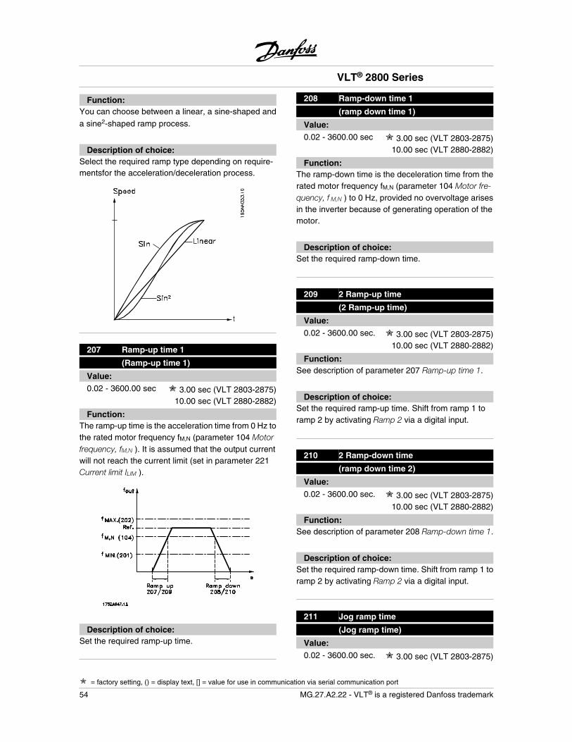
Function:You can choose between a linear, a sine-shaped and
a sine2-shaped ramp process.
Description of choice:Select the required ramp type depending on require-mentsfor the acceleration/deceleration process.
207 Ramp-up time 1
(Ramp-up time 1)
Value:0.02 - 3600.00 sec 3.00 sec (VLT 2803-2875)
10.00 sec (VLT 2880-2882)
Function:The ramp-up time is the acceleration time from 0 Hz tothe rated motor frequency fM,N (parameter 104 Motorfrequency, fM,N ). It is assumed that the output currentwill not reach the current limit (set in parameter 221Current limit ILIM ).
Description of choice:Set the required ramp-up time.
208 Ramp-down time 1
(ramp down time 1)
Value:0.02 - 3600.00 sec 3.00 sec (VLT 2803-2875)
10.00 sec (VLT 2880-2882)
Function:The ramp-down time is the deceleration time from therated motor frequency fM,N (parameter 104 Motor fre-quency, f M,N ) to 0 Hz, provided no overvoltage arisesin the inverter because of generating operation of themotor.
Description of choice:Set the required ramp-down time.
209 2 Ramp-up time
(2 Ramp-up time)
Value:0.02 - 3600.00 sec. 3.00 sec (VLT 2803-2875)
10.00 sec (VLT 2880-2882)
Function:See description of parameter 207 Ramp-up time 1.
Description of choice:Set the required ramp-up time. Shift from ramp 1 toramp 2 by activating Ramp 2 via a digital input.
210 2 Ramp-down time
(ramp down time 2)
Value:0.02 - 3600.00 sec. 3.00 sec (VLT 2803-2875)
10.00 sec (VLT 2880-2882)
Function:See description of parameter 208 Ramp-down time 1.
Description of choice:Set the required ramp-down time. Shift from ramp 1 toramp 2 by activating Ramp 2 via a digital input.
211 Jog ramp time
(Jog ramp time)
Value:0.02 - 3600.00 sec. 3.00 sec (VLT 2803-2875)
VLT® 2800 Series
= factory setting, () = display text, [] = value for use in communication via serial communication port
54 MG.27.A2.22 - VLT® is a registered Danfoss trademark
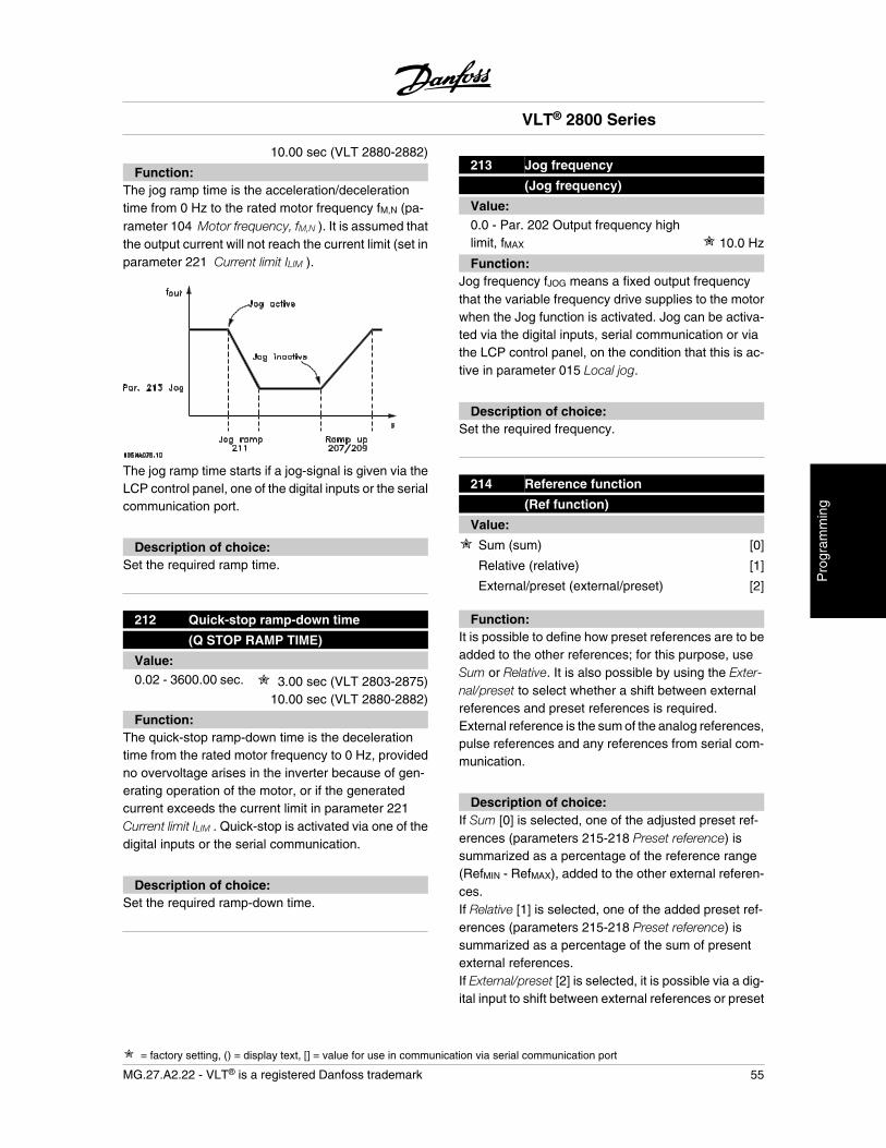
10.00 sec (VLT 2880-2882)
Function:The jog ramp time is the acceleration/decelerationtime from 0 Hz to the rated motor frequency fM,N (pa-rameter 104 Motor frequency, fM,N ). It is assumed thatthe output current will not reach the current limit (set inparameter 221 Current limit ILIM ).
The jog ramp time starts if a jog-signal is given via theLCP control panel, one of the digital inputs or the serialcommunication port.
Description of choice:Set the required ramp time.
212 Quick-stop ramp-down time
(Q STOP RAMP TIME)
Value:0.02 - 3600.00 sec. 3.00 sec (VLT 2803-2875)
10.00 sec (VLT 2880-2882)
Function:The quick-stop ramp-down time is the decelerationtime from the rated motor frequency to 0 Hz, providedno overvoltage arises in the inverter because of gen-erating operation of the motor, or if the generatedcurrent exceeds the current limit in parameter 221Current limit ILIM . Quick-stop is activated via one of thedigital inputs or the serial communication.
Description of choice:Set the required ramp-down time.
213 Jog frequency
(Jog frequency)
Value:0.0 - Par. 202 Output frequency highlimit, fMAX 10.0 Hz
Function:Jog frequency fJOG means a fixed output frequencythat the variable frequency drive supplies to the motorwhen the Jog function is activated. Jog can be activa-ted via the digital inputs, serial communication or viathe LCP control panel, on the condition that this is ac-tive in parameter 015 Local jog.
Description of choice:Set the required frequency.
214 Reference function
(Ref function)
Value:
Sum (sum) [0]
Relative (relative) [1]
External/preset (external/preset) [2]
Function:It is possible to define how preset references are to beadded to the other references; for this purpose, useSum or Relative. It is also possible by using the Exter-nal/preset to select whether a shift between externalreferences and preset references is required.External reference is the sum of the analog references,pulse references and any references from serial com-munication.
Description of choice:If Sum [0] is selected, one of the adjusted preset ref-erences (parameters 215-218 Preset reference) issummarized as a percentage of the reference range(RefMIN - RefMAX), added to the other external referen-ces.If Relative [1] is selected, one of the added preset ref-erences (parameters 215-218 Preset reference) issummarized as a percentage of the sum of presentexternal references.If External/preset [2] is selected, it is possible via a dig-ital input to shift between external references or preset
VLT® 2800 Series
= factory setting, () = display text, [] = value for use in communication via serial communication port
MG.27.A2.22 - VLT® is a registered Danfoss trademark 55
Pro
gram
min
g
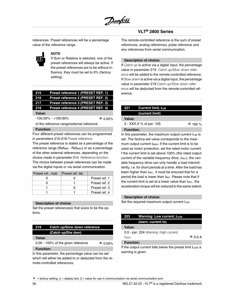
references. Preset references will be a percentagevalue of the reference range.
NOTEIf Sum or Relative is selected, one of thepreset references will always be active. Ifthe preset references are to be without in-fluence, they must be set to 0% (factorysetting).
215 Preset reference 1 (PRESET REF. 1)216 Preset reference 2 (PRESET REF. 2)217 Preset reference 3 (PRESET REF. 3)218 Preset reference 4 (PRESET REF. 4)
Value:-100.00% - +100.00% 0.00%
of the reference range/external reference
Function:Four different preset references can be programmedin parameters 215-218 Preset reference.The preset reference is stated as a percentage of thereference range (RefMIN - RefMAX) or as a percentageof the other external references, depending on thechoice made in parameter 214 Reference function.The choice between preset references can be madevia the digital inputs or via serial communication.
Preset ref., msb Preset ref. lsb0 0 Preset ref. 10 1 Preset ref. 21 0 Preset ref. 31 1 Preset ref. 4
Description of choice:Set the preset reference(s) that is/are to be the op-tions.
219 Catch up/Slow down reference
(Catch up/Slw dwn)
Value:0.00 - 100% of the given reference 0.00%
Function:In this parameter, the percentage value can be setwhich will either be added to or deducted from the re-mote-controlled references.
The remote-controlled reference is the sum of presetreferences, analog references, pulse reference andany references from serial communication.
Description of choice:If Catch up is active via a digital input, the percentagevalue in parameter 219 Catch up/Slow down refer-ence will be added to the remote-controlled reference.If Slow down is active via a digital input, the percentagevalue in parameter 219 Catch up/Slow down refer-ence will be deducted from the remote-controlled ref-erence.
221 Current limit, ILIM
(current limit)
Value:0 - XXX.X % of par. 105 160 %
Function:In this parameter, the maximum output current ILIM isset. The factory-set value corresponds to the maxi-mum output current IMAX. If the current limit is to beused as motor protection, set the rated motor current.f the current limit is set above 100% (the rated outputcurrent of the variable frequency drive, IINV.), the vari-able frequency drive can only handle a load intermit-tently, i.e. for short periods at a time. After the load hasbeen higher than IINV., it must be ensured that for aperiod the load is lower than IINV. Please note that ifthe current limit is set at a lower value than IINV., theacceleration torque will be reduced to the same extent.
Description of choice:Set the required maximum output current ILIM.
223 Warning: Low current, ILOW
(warn. current lo)
Value:0.0 - par. 224 Warning: High current,IHIGH 0.0 A
Function:If the output current falls below the preset limit ILOW awarning is given.
VLT® 2800 Series
= factory setting, () = display text, [] = value for use in communication via serial communication port
56 MG.27.A2.22 - VLT® is a registered Danfoss trademark
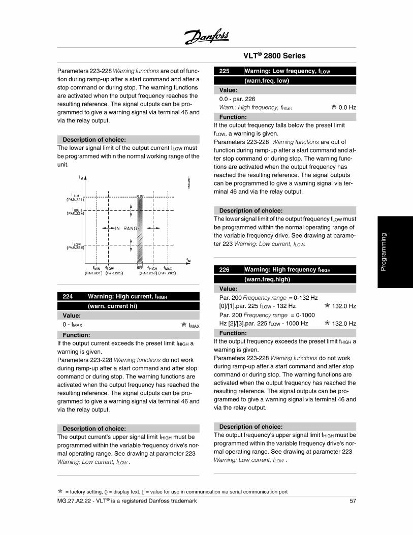
Parameters 223-228 Warning functions are out of func-tion during ramp-up after a start command and after astop command or during stop. The warning functionsare activated when the output frequency reaches theresulting reference. The signal outputs can be pro-grammed to give a warning signal via terminal 46 andvia the relay output.
Description of choice:The lower signal limit of the output current ILOW mustbe programmed within the normal working range of theunit.
224 Warning: High current, IHIGH
(warn. current hi)
Value:0 - IMAX IMAX
Function:If the output current exceeds the preset limit IHIGH awarning is given.Parameters 223-228 Warning functions do not workduring ramp-up after a start command and after stopcommand or during stop. The warning functions areactivated when the output frequency has reached theresulting reference. The signal outputs can be pro-grammed to give a warning signal via terminal 46 andvia the relay output.
Description of choice:The output current's upper signal limit IHIGH must beprogrammed within the variable frequency drive's nor-mal operating range. See drawing at parameter 223Warning: Low current, ILOW .
225 Warning: Low frequency, fLOW
(warn.freq. low)
Value:0.0 - par. 226Warn.: High frequency, fHIGH 0.0 Hz
Function:If the output frequency falls below the preset limitfLOW, a warning is given.Parameters 223-228 Warning functions are out offunction during ramp-up after a start command and af-ter stop command or during stop. The warning func-tions are activated when the output frequency hasreached the resulting reference. The signal outputscan be programmed to give a warning signal via ter-minal 46 and via the relay output.
Description of choice:The lower signal limit of the output frequency fLOW mustbe programmed within the normal operating range ofthe variable frequency drive. See drawing at parame-ter 223 Warning: Low current, ILOW.
226 Warning: High frequency fHIGH
(warn.freq.high)
Value:Par. 200 Frequency range = 0-132 Hz[0]/[1].par. 225 fLOW - 132 Hz 132.0 Hz
Par. 200 Frequency range = 0-1000Hz [2]/[3].par. 225 fLOW - 1000 Hz 132.0 Hz
Function:If the output frequency exceeds the preset limit fHIGH awarning is given.Parameters 223-228 Warning functions do not workduring ramp-up after a start command and after stopcommand or during stop. The warning functions areactivated when the output frequency has reached theresulting reference. The signal outputs can be pro-grammed to give a warning signal via terminal 46 andvia the relay output.
Description of choice:The output frequency's upper signal limit fHIGH must beprogrammed within the variable frequency drive's nor-mal operating range. See drawing at parameter 223Warning: Low current, ILOW .
VLT® 2800 Series
= factory setting, () = display text, [] = value for use in communication via serial communication port
MG.27.A2.22 - VLT® is a registered Danfoss trademark 57
Pro
gram
min
g
227 Warning: Low feedback, FBLOW
(warn.feedb. low)
Value:-100,000.000 - par. 228 Warn.:FBHIGH -4000.000
Function:If the feedback signal falls below the preset limitFBLOW, a warning is given.Parameters 223-228 Warning functions are out offunction during ramp-up after a start command and af-ter a stop command or during stop. The warning func-tions are activated when the output frequency hasreached the resulting reference.The signal outputscan be programmed to give a warning signal via ter-minal 46 and via the relay output.The unit for feedbackin Closed loop is programmed in parameter 416 Proc-ess units.
Description of choice:Set the required value within the feedback range (pa-rameter 414 Minimum feedback, FBMIN and 415 Max-imum feedback, FBMAX ).
228 Warning: High feedback, FBHIGH
(warn.feedb high)
Value:Par. 227 Warn.: FBLOW - 100,000.000 4000.000
Function:If the feedback signal gets above the preset limitFBHIGH, a warning is given.Parameters 223-228 Warning functions are out offunction during ramp-up after a start command and af-ter a stop command or during stop. The warning func-tions are activated when the output frequency hasreached the resulting reference. The signal outputscan be programmed to give a warning signal via ter-minal 46 and via the relay output. The unit for feedbackin Closed loop is programmed in parameter 416 Proc-ess units.
Description of choice:Set the required value within the feedback range (pa-rameter 414 Minimum feedback, FBMIN and 415 Max-imum feedback, FBMAX ).
229 Frequency bypass, bandwidth
(FREQ BYPASS B.W.)
Value:0 (OFF) - 100 Hz 0 Hz
Function:Some systems call for some output frequencies to beavoided because of mechanical resonance problemsin the system. In parameters 230-231 Frequency by-pass, these output frequencies can be programmed.In this parameter, a bandwidth can be defined on eitherside of these frequencies.
Description of choice:The frequency set in this parameter will be centeredaround parameters 230 Frequency bypass 1 and 231Frequency bypass 2.
230 Frequency bypass 1 (FREQ. BYPASS 1)231 Frequency bypass 2 (FREQ. BYPASS 2)
Value:0 - 1000 Hz 0.0 Hz
Function:Some systems call for some output frequencies to beavoided because of mechanical resonance problemsin the system.
Description of choice:Enter the frequencies to be avoided. See also param-eter 229 Frequency bypass, bandwidth.
VLT® 2800 Series
= factory setting, () = display text, [] = value for use in communication via serial communication port
58 MG.27.A2.22 - VLT® is a registered Danfoss trademark

Inputs and Outputs
Digital inputs Term. no. 181 191 27 29 33
par. no. 302 303 304 305 307Value:No function (NO OPERATION) [0] [0] [0] [0] [0]Reset (RESET) [1] [1] [1] [1] [1]Coasting stop inverse (MOTOR COAST INVERSE) [2] [2] [2] [2] [2]Reset and coasting inverse (RESET AND COAST INV.) [3] [3] [3] [3] [3]
Quick-stop inverse (QUICK-STOP INVERSE) [4] [4] [4] [4] [4]DC braking inverse (DC BRAKE INVERSE) [5] [5] [5] [5] [5]Stop inverse (STOP INVERSE) [6] [6] [6] [6] [6]Start (START) [7] [7] [7] [7] [7]
Pulse start (LATCHED START) [8] [8] [8] [8] [8]Reversing (REVERSING) [9] [9] [9] [9] [9]
Reversing and start (START REVERSING) [10] [10] [10] [10] [10]Start clockwise (ENABLE FORWARD) [11] [11] [11] [11] [11]Start counter-clockwise (ENABLE REVERSE) [12] [12] [12] [12] [12]Jog (JOGGING) [13] [13] [13]
[13][13]
Freeze reference (FREEZE REFERENCE) [14] [14] [14] [14] [14]Freeze output frequency (FREEZE OUTPUT) [15] [15] [15] [15] [15]Speed up (SPEED UP) [16] [16] [16] [16] [16]Slow (SLOW) [17] [17] [17] [17] [17]Catch-up (CATCH-UP) [19] [19] [19] [19] [19]Slow-down (SLOW-DOWN) [20] [20] [20] [20] [20]Ramp 2 (RAMP 2) [21] [21] [21] [21] [21]Preset ref, LSB (PRESET REF, LSB) [22] [22] [22] [22] [22]Preset ref, MSB (PRESET REF, MSB) [23] [23] [23] [23] [23]Preset reference on (PRESET REFERENCE ON) [24] [24] [24] [24] [24]Thermistor (THERMISTOR) [25] [25] [25] [25]Precise stop, inverse (PRECISE STOP INV.) [26] [26]Precise start/stop (PRECISE START/STOP) [27] [27]Pulse reference (PULSE REFERENCE) [28]Pulse feedback (PULSE FEEDBACK) [29]Pulse input (PULSE INPUT) [30]Selection of Set-up, lsb (SET-UP SELECT LSB) [31] [31] [31] [31] [31]Selection of Set-up, msb (SET-UP SELECT MSB) [32] [32] [32] [32] [32]Reset and start (RESET AND START) [33] [33] [33] [33] [33]Pulse counter start (PULSE COUNTER START) [34] [34]
1. All functions on terminals 18 and 19 are controlledby an interrupter, which means that the repetitive ac-curacy of the response time is constant. Can be usedfor start/stop, set-up switch, and especially for chang-ing digital preset, i.e., to obtain a reproducible stoppoint when using creep speed. For further information,see VLT 2800 Precise Stop Instruction, MI.28.CX.02.
Function:In these parameters, 302-307 Digital inputs, it is pos-sible to choose between the different enabled func-tions related to the digital inputs (terminals 18-33).
VLT® 2800 Series
= factory setting, () = display text, [] = value for use in communication via serial communication port
MG.27.A2.22 - VLT® is a registered Danfoss trademark 59
Pro
gram
min
g
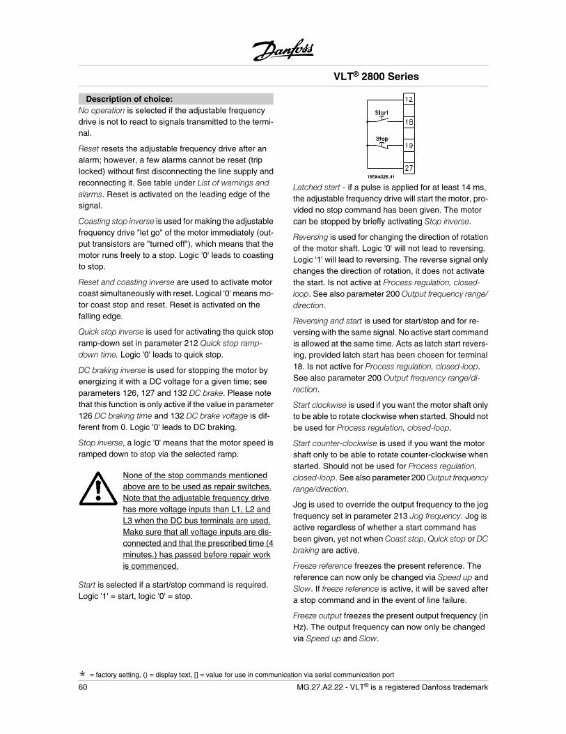
Description of choice:No operation is selected if the adjustable frequencydrive is not to react to signals transmitted to the termi-nal.
Reset resets the adjustable frequency drive after analarm; however, a few alarms cannot be reset (triplocked) without first disconnecting the line supply andreconnecting it. See table under List of warnings andalarms. Reset is activated on the leading edge of thesignal.
Coasting stop inverse is used for making the adjustablefrequency drive "let go" of the motor immediately (out-put transistors are "turned off"), which means that themotor runs freely to a stop. Logic '0' leads to coastingto stop.
Reset and coasting inverse are used to activate motorcoast simultaneously with reset. Logical '0' means mo-tor coast stop and reset. Reset is activated on thefalling edge.
Quick stop inverse is used for activating the quick stopramp-down set in parameter 212 Quick stop ramp-down time. Logic '0' leads to quick stop.
DC braking inverse is used for stopping the motor byenergizing it with a DC voltage for a given time; seeparameters 126, 127 and 132 DC brake. Please notethat this function is only active if the value in parameter126 DC braking time and 132 DC brake voltage is dif-ferent from 0. Logic '0' leads to DC braking.
Stop inverse, a logic '0' means that the motor speed isramped down to stop via the selected ramp.
None of the stop commands mentionedabove are to be used as repair switches.Note that the adjustable frequency drivehas more voltage inputs than L1, L2 andL3 when the DC bus terminals are used.Make sure that all voltage inputs are dis-connected and that the prescribed time (4minutes.) has passed before repair workis commenced.
Start is selected if a start/stop command is required.Logic '1' = start, logic '0' = stop.
Latched start - if a pulse is applied for at least 14 ms,the adjustable frequency drive will start the motor, pro-vided no stop command has been given. The motorcan be stopped by briefly activating Stop inverse.
Reversing is used for changing the direction of rotationof the motor shaft. Logic '0' will not lead to reversing.Logic '1' will lead to reversing. The reverse signal onlychanges the direction of rotation, it does not activatethe start. Is not active at Process regulation, closed-loop. See also parameter 200 Output frequency range/direction.
Reversing and start is used for start/stop and for re-versing with the same signal. No active start commandis allowed at the same time. Acts as latch start revers-ing, provided latch start has been chosen for terminal18. Is not active for Process regulation, closed-loop.See also parameter 200 Output frequency range/di-rection.
Start clockwise is used if you want the motor shaft onlyto be able to rotate clockwise when started. Should notbe used for Process regulation, closed-loop.
Start counter-clockwise is used if you want the motorshaft only to be able to rotate counter-clockwise whenstarted. Should not be used for Process regulation,closed-loop. See also parameter 200 Output frequencyrange/direction.
Jog is used to override the output frequency to the jogfrequency set in parameter 213 Jog frequency. Jog isactive regardless of whether a start command hasbeen given, yet not when Coast stop, Quick stop or DCbraking are active.
Freeze reference freezes the present reference. Thereference can now only be changed via Speed up andSlow. If freeze reference is active, it will be saved aftera stop command and in the event of line failure.
Freeze output freezes the present output frequency (inHz). The output frequency can now only be changedvia Speed up and Slow.
VLT® 2800 Series
= factory setting, () = display text, [] = value for use in communication via serial communication port
60 MG.27.A2.22 - VLT® is a registered Danfoss trademark
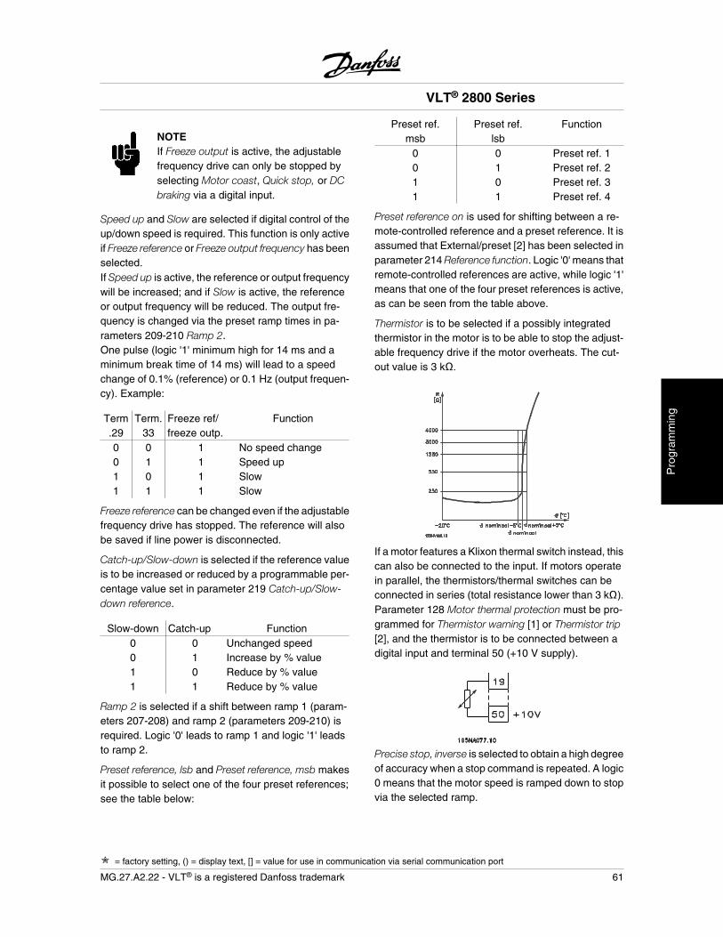
NOTEIf Freeze output is active, the adjustablefrequency drive can only be stopped byselecting Motor coast, Quick stop, or DCbraking via a digital input.
Speed up and Slow are selected if digital control of theup/down speed is required. This function is only activeif Freeze reference or Freeze output frequency has beenselected.If Speed up is active, the reference or output frequencywill be increased; and if Slow is active, the referenceor output frequency will be reduced. The output fre-quency is changed via the preset ramp times in pa-rameters 209-210 Ramp 2.One pulse (logic '1' minimum high for 14 ms and aminimum break time of 14 ms) will lead to a speedchange of 0.1% (reference) or 0.1 Hz (output frequen-cy). Example:
Term.29
Term.33
Freeze ref/freeze outp.
Function
0 0 1 No speed change0 1 1 Speed up1 0 1 Slow1 1 1 Slow
Freeze reference can be changed even if the adjustablefrequency drive has stopped. The reference will alsobe saved if line power is disconnected.
Catch-up/Slow-down is selected if the reference valueis to be increased or reduced by a programmable per-centage value set in parameter 219 Catch-up/Slow-down reference.
Slow-down Catch-up Function0 0 Unchanged speed0 1 Increase by % value1 0 Reduce by % value1 1 Reduce by % value
Ramp 2 is selected if a shift between ramp 1 (param-eters 207-208) and ramp 2 (parameters 209-210) isrequired. Logic '0' leads to ramp 1 and logic '1' leadsto ramp 2.
Preset reference, lsb and Preset reference, msb makesit possible to select one of the four preset references;see the table below:
Preset ref.msb
Preset ref.lsb
Function
0 0 Preset ref. 10 1 Preset ref. 21 0 Preset ref. 31 1 Preset ref. 4
Preset reference on is used for shifting between a re-mote-controlled reference and a preset reference. It isassumed that External/preset [2] has been selected inparameter 214 Reference function. Logic '0' means thatremote-controlled references are active, while logic '1'means that one of the four preset references is active,as can be seen from the table above.
Thermistor is to be selected if a possibly integratedthermistor in the motor is to be able to stop the adjust-able frequency drive if the motor overheats. The cut-out value is 3 k .
If a motor features a Klixon thermal switch instead, thiscan also be connected to the input. If motors operatein parallel, the thermistors/thermal switches can beconnected in series (total resistance lower than 3 k ).Parameter 128 Motor thermal protection must be pro-grammed for Thermistor warning [1] or Thermistor trip[2], and the thermistor is to be connected between adigital input and terminal 50 (+10 V supply).
Precise stop, inverse is selected to obtain a high degreeof accuracy when a stop command is repeated. A logic0 means that the motor speed is ramped down to stopvia the selected ramp.
VLT® 2800 Series
= factory setting, () = display text, [] = value for use in communication via serial communication port
MG.27.A2.22 - VLT® is a registered Danfoss trademark 61
Pro
gram
min
g
Precise start/stop is selected to obtain a high degreeof accuracy when a start and stop command is repea-ted.
Pulse reference is selected if the reference signal ap-plied is a pulse train (frequency). 0 Hz corresponds toparameter 204 Minimum reference, RefMIN . The fre-quency, set in parameter 327 Pulse reference/feed-back, corresponds to parameter 205 Maximum refer-ence RefMAX .
Pulse feedback is selected if the feedback signal usedis a pulse train (frequency). In parameter 327 Pulsereference/feedback, the maximum pulse feedback fre-quency is set.
Pulse input is selected if a specific number of pulsesmust lead to a Precise stop; see parameter 343 Precisestop and parameter 344 Counter value.
Selection of Set-up, lsb and Selection of Set-up, msbprovides the option of selecting one of the four set-ups.It is, however, a condition that parameter 004 is set toMulti-set-up.
Reset and start can be used as a start function. If 24 Vare connected to the digital input, this will cause theadjustable frequency drive to reset, and the motor willramp up to the preset reference.
Pulse counter start is used to start a counter stop se-quence with a pulse signal. The pulse width must beat least 14 ms and not longer than the count period.See also parameter 343 and the instruction,MI28CXYY.
308 Terminal 53, analogue input voltage
(AI [V]53FUNCT.)
Value:
No function (NO OPERATION) [0]
Reference (reference) [1]
Feedback (feedback) [2]
Wobble (WOBB.DELTA FREQ [%]) [10]
Function:In this parameter, it is possible to select the functionrequired to be connected to terminal 53. Scaling of theinput signal is made in parameter 309 Terminal 53, min.scaling and parameter 310 Terminal 53, max. scaling.
Description of choice:No function [0]. Is selected if the adjustable frequencydrive is not to react to signals connected to the termi-nal. Reference [1]. If this function is selected, the ref-erence can be changed by means of an analogreference signal. If reference signals are connected tomore than one input, these reference signals must beadded up.If a voltage feedback signal is connected,select Feedback [2] on terminal 53.Wobble [10]The delta frequency can be controlled by the analoginput. If WOBB.DELTA FREQ is selected as analog in-put (par. 308 or par. 314) the value selected in par. 702equals 100 % analog input.Example: Analog input = 4-20 mA, Delta freq. par. 702= 5 Hz • 4 mA = 0 Hz and 20 mA = 5 Hz. If this functionis chosen, see Wobble Instruction MI28JXYY for fur-ther information.
309 Terminal 53 Min. scaling
(AI 53 SCALE LOW)
Value:0.0 - 10.0 Volt 0.0 Volt
Function:This parameter is used for setting the signal value thatis to correspond to the minimum reference or the min-imum feedback, parameter 204 Minimum reference,RefMIN / 414 Minimum feedback, FBMIN.
Description of choice:Set the required voltage value. For reasons of accu-racy, compensation should be made for voltage lossin long signal cables. If the Time out function is to beused (parameter 317 Time out and 318 Function aftertime out), the value set must be higher than 1 Volt.
310 Terminal 53 Max. scaling
(AI 53 SCALE HIGH)
Value:0 - 10.0 Volt 10.0 Volt
Function:This parameter is used for setting the signal value thatis to correspond to the maximum reference value or
VLT® 2800 Series
= factory setting, () = display text, [] = value for use in communication via serial communication port
62 MG.27.A2.22 - VLT® is a registered Danfoss trademark
maximum feedback, parameter 205 Maximum refer-ence, RefMAX / 414 Maximum feedback, FBMAX .
Description of choice:Set the required voltage value. For reasons of accu-racy, compensation should be made for voltage lossesin long signal cables.
314 Terminal 60, analogue input current
(AI [mA] 60 FUNCT)
Value:
No function (no operation) [0]
Reference (reference) [1]
Feedback (feedback) [2]
Wobble (WOBB.DELTA FREQ [%]) [10]
Function:This parameter allows a choice between the differentfunctions available for the input, terminal 60. Scalingof the input signal is effected in parameter 315 Terminal60, min. scaling and parameter 316 Terminal 60, max.scaling.
Description of choice:No function [0]. Is selected if the adjustable frequencydrive is not to react to signals connected to the termi-nal. Reference [1]. If this function is selected, the ref-erence can be changed by means of an analogreference signal. If reference signals are connected tomore than one input, these reference signals must beadded up.If one current feedback signal is connected, selectFeedback [2] on terminal 60.Wobble [10]The delta frequency can be controlled by the analoginput. If WOBB.DELTA FREQ is selected as analog in-put (par. 308 or par. 314) the value selected in par. 702equals 100 % analog input.Example: Analog input = 4-20 mA, Delta freq. par. 702= 5 Hz • 4 mA = 0 Hz and 20 mA = 5 Hz. If this functionis chosen, see Wobble Instruction MI28JXYY for fur-ther information.
315 Terminal 60 Min. scaling
(AI 60 SCALE LOW)
Value:0.0 - 20.0 mA 4.0 mA
Function:In this parameter, you can set the signal value that willcorrespond to the minimum reference or minimumfeedback, parameter 204 Minimum reference, RefMIN /414 Minimum feedback, FBMIN .
Description of choice:Set the required current value. If the Timeout functionis to be used (parameter 317 Time out and 318 Func-tion after time out ), the value set must be higher than2 mA.
316 Terminal 60 Max. scaling
(AI 60 SCALE HIGH)
Value:0.0 - 20.0 mA 20.0 mA
Function:This parameter is used for setting the signal value thatis to correspond to the maximum reference value, pa-rameter 205 Maximum reference value, RefMAX .
Description of choice:Set the required current value.
317 Time out
(LIVE ZERO TIME O)
Value:1 - 99 sec. 10 sec.
Function:If the signal value of the reference or feedback signalconnected to one of the input terminals 53 or 60 fallsbelow 50 % of the minimum scaling for a period longerthan the time set, the function selected in parameter318 Function after time out will be activated. This func-tion is only active if in parameter 309 Terminal 53, min.scaling a value higher than 1 Volt has been selected,or if in parameter 315 Terminal 60, min. scaling a valuehigher than 2 mA has been selected.
VLT® 2800 Series
= factory setting, () = display text, [] = value for use in communication via serial communication port
MG.27.A2.22 - VLT® is a registered Danfoss trademark 63
Pro
gram
min
g
Description of choice:Set the required time.
318 Function after time out
(LIVE ZERO FUNCT.)
Value:
No operation (NO OPERATION) [0]
Freeze output frequency(FREEZE OUTPUT FREQ.) [1]
Stop (stop) [2]
Jog (jog) [3]
Max. speed (MAX SPEED) [4]
Stop and trip (STOP AND TRIP) [5]
Function:This parameter allows a choice of the function to beactivated after the expiry of the Time out (parameter317 Time out ). If a time-out function occurs at the sametime as a bus time-out function (parameter 513 Bustime interval function ), the time-out function in param-eter 318 will be activated.
Description of choice:The output frequency of the adjustable frequency drivecan be:
- frozen at the present frequency [1]
- overruled to stop [2]
- overruled to jog frequency [3]
- overruled to max. output frequency [4]
- overruled to stop with subsequent trip [5]
319 Analog output terminal 42
(AO 42 FUNCTION)
Value:
No function (NO OPERATION) [0]
External reference min.-max. 0-20 mA(ref min-max = 0-20 mA) [1]
External reference min.-max. 4-20 mA(ref min-max = 4-20 mA) [2]
Feedback min.-max. 0-20 mA(fb min-max = 0-20 mA) [3]
Feedback min.-max. 4-20 mA [4]
(fb min-max = 4-20 mA)
Output frequency 0-max 0-20 mA(0-fmax = 0-20 mA) [5]
Output frequency 0-max 4-20 mA(0-fmax = 4-20 mA) [6]
Output current 0-IINV 0-20 mA(0-iinv = 0-20 mA) [7]
Output current 0-IIINV 4-20 mA(0-iinv = 4-20 mA) [8]
Output power 0-PM,N 0-20 mA(0-Pnom = 0-20 mA) [9]
Output power 0-PM,N 4-20 mA(0-Pnom = 4-20 mA) [10]
Inverter temperature 68-212 °F [20-100 °C]0-20 mA(TEMP 20-100 C=0-20 mA) [11]
Inverter temperature 68-212 °F [20-100 °C]4-20 mA(TEMP 20-100 C=4-20 mA) [12]
Function:The analog output can be used for stating a processvalue. It is possible to choose two types of output sig-nals 0-20 mA or 4-20 mA.If used as a voltage output (0-10 V), a pull-down re-sistor of 500 must be fitted to common (terminal 55).If the output is used as a current output, the resultingresistance from the equipment connected may not ex-ceed 500 .
Description of choice:No function. Is selected if the analog output is not to beused.
External RefMIN - RefMAX 0-20 mA/4-20 mA.An output signal is obtained, which is proportional tothe resulting reference value in the interval Minimumreference, RefMIN - Maximum reference, RefMAX (pa-rameters 204/205).
FBMIN-FBMAX 0-20 mA/ 4-20 mA.An output signal is obtained, which is proportional tothe feedback value in the interval Minimum feedback,FBMIN - Maximum feedback, FBMAX (parameter414/415).
0-fMAX 0-20 mA/4-20 mA.
VLT® 2800 Series
= factory setting, () = display text, [] = value for use in communication via serial communication port
64 MG.27.A2.22 - VLT® is a registered Danfoss trademark
An output signal is obtained, which is proportional tothe output frequency in the interval 0 - fMAX (parameter202 Output frequency, high limit, fMAX ).
0 - IINV 0-20 mA/4-20 mA.An output signal is obtained, which is proportional tothe output current in the interval 0 - IINV
0 - PM,N 0-20 mA/4-20 mA.An output signal is obtained, which is proportional tothe present output power. 20 mA corresponds to thevalue set in parameter 102 Motor power, PM,N.
0 - Temp.MAX 0-20 mA/4-20 mA.An output signal is obtained, which is proportional tothe present heatsink temperature. 0/4 mA corre-sponds to a heatsink temperature of less than 68 °F[20 °C], and 20 mA corresponds to 100 °C.
323 Relay output 1-3
(RELAY 1-3 FUNCT.)
Value:
No function (no operation) [0]
Unit ready (unit ready) [1]
Enable/no warning (enable/no warning) [2]
Running (RUNNING) [3]
Running in reference, no warning(run on ref/no warn) [4]
Running, no warnings(RUNNING/NO WARNING) [5]
Running in reference range, no warnings(RUN IN RANGE/ NO WARN) [6]
Ready - AC line voltage within range(RDY NO OVER/UNDERVOL) [7]
Alarm or warning(ALARM OR WARNING) [8]
Current higher than current limit, par. 221(Current limit) [9]
Alarm (ALARM) [10]
Output frequency higher than fLOW par. 225(above frequency low) [11]
Output frequency lower than fHIGH par. 226(below frequency high) [12]
Output current higher than ILOW par. 223(above current low) [13]
Output current lower than IHIGH par. 224(below current high) [14]
Feedback higher than FBLOW par. 227(above feedback low) [15]
Feedback lower than FBHIGH par. 228(under feedback high) [16]
Relay 123 (RELAY 123) [17]
Reversing (REVERSE) [18]
Thermal warning (THERMAL WARNING) [19]
Local operation (LOCAL MODE) [20]
Out of frequency range par. 225/226(out of freq. range) [22]
Out of current range(out of current range) [23]
Out of feedback range(out of fdbk. range) [24]
Mechanical brake control(Mech. brake control) [25]
Control word bit 11(control word bit 11) [26]
Function:The relay output can be used for giving the presentstatus or warning. The output is activated (1-2 make)when a given condition is fulfilled.
Description of choice:No function is selected if the adjustable frequency driveis not to react to signals.
Unit ready: there is a supply voltage on the control cardof the adjustable frequency drive, and the adjustablefrequency drive is ready for operation.
Enable, no warning: the adjustable frequency drive isready for operation, but no start command has beengiven. No warning.
Running is active when there is a start command or theoutput frequency is above 0.1 Hz. Also active duringramp-down.
Running in reference, no warning: speed according toreference.
Running, no warning: a start command has been given.No warning.
Ready - line voltage within range: the adjustable fre-quency drive is ready for use, the control card is re-ceiving supply voltage, and there are no active controlsignals on the inputs. The AC line voltage lies withinthe voltage limits.
VLT® 2800 Series
= factory setting, () = display text, [] = value for use in communication via serial communication port
MG.27.A2.22 - VLT® is a registered Danfoss trademark 65
Pro
gram
min
g
Alarm or warning: the output is activated by an alarmor warning.
Current limit: the output current is higher than the valueprogrammed in parameter 221 Current limit I LIM.
Alarm: the output is activated by an alarm.
Output frequency higher than fLOW: the output frequen-cy is higher than the value set in parameter 225Warning: Low frequency, fLOW .
Output frequency lower than fHIGH : the output frequen-cy is lower than the value set in parameter 226 Warn-ing: High frequency, fHIGH .
Output current higher than ILOW : the output current ishigher than the value set in parameter 223 Warning:Low current, ILOW .
Output current lower than IHIGH : the output current islower than the value set in parameter 224 Warning:High current, IHIGH .
Feedback higher than FBLOW : the feedback value ishigher than the value set in parameter 227 Warning:Low feedback, FBLOW .
Feedback lower than FBHIGH : the feedback value islower than the value set in parameter 228 Warning:High current, IHIGH .
Relay 123 is only used in connection with Profidrive.
Reversing: the relay output is activated when the di-rection of motor rotation is counter-clockwise. Whenthe direction of motor rotation is clockwise, the valueis 0 V DC.
Thermal warning: above the temperature limit in eitherthe motor or the adjustable frequency drive, or from athermistor connected to a digital input.
Local operation: the output is active when in parameter002 Local/remote operation, Local operation [1] hasbeen selected.
Out of the frequency range: the output frequency is outof the programmed frequency range in parameters225 and 226.
Out of the current range: the motor current is out of theprogrammed range in parameters 223 and 224.
Out of the feedback range: the feedback signal is outof the programmed range in parameters 227 and 228.
Mechanical brake control: enables you to control anexternal mechanical brake (see section about controlof mechanical brake in the VLT 2800 Design Guide).
327 Pulse/reference feedback
(PULSE REF/FB MAX)
Value:150 - 67600 Hz 5000 Hz
Function:This parameter is used for setting the signal value thatcorresponds to the maximum value set in parameter205 Maximum reference, RefMAX or to the maximumfeedback value set in parameter 415 Maximum feed-back, FBMAX .
Description of choice:Set the required pulse reference or pulse feedback tobe connected to terminal 33.
328 Maximum Pulse 29
(MAX PULSE 29)
Value:150 - 67600 Hz 5000 Hz
Function:This parameter is used for setting the signal value thatcorresponds to the maximum value set in parameter205 Maximum reference, RefMAX or to the maximumfeedback value set in parameter 415 Maximum feed-back, FBMAX .
NOTEOnly relevant for DeviceNet. SeeMG90BXYY for further information.
341 Digital / pulse output terminal 46
(DO 46 FUNCTION)
Value:
Unit ready (Unit ready) [0]
Parameter [0] - [20] see parameter 323
Pulse reference (PULSE REFERENCE) [21]
Parameter [22] - [25] see parameter 323
VLT® 2800 Series
= factory setting, () = display text, [] = value for use in communication via serial communication port
66 MG.27.A2.22 - VLT® is a registered Danfoss trademark
Pulse feedback (PULSE FEEDBACK) [26]
Output frequency (PULSE OUTPUTFREQ) [27]
Pulse current (PULSE CURRENT) [28]
Pulse power (PULSE POWER) [29]
Pulse temperature (PULSE TEMP) [30]
Function:The digital output can be used for giving the presentstatus or warning. The digital output (terminal 46) givesa 24 V DC signal when a given condition is fulfilled.Terminal can also be used for frequency output.Parameter 342 sets the maximum pulse frequency.
Description of choice:Pulse reference RefMIN - Ref MAX
An output signal is obtained, which is proportional tothe resulting reference value in the interval Minimumreference, Ref MIN - Maximum reference, RefMAX (pa-rameters 204/205).
Pulse feedback FBMIN-FBMAX .An output signal is obtained, which is proportional tothe feedback value in the interval Minimum feedback,FBMIN - Maximum feedback, FBMAX (parameter414/415).
Output frequency 0-fMAX.An output signal is obtained, which is proportional tothe output frequency in the interval 0 - fMAX (parameter202 Output frequency, high limit, fMAX ).
Pulse current 0 - IINV..An output signal is obtained, which is proportional tothe output current in the interval 0 - IINV.
Pulse power 0 - PM,N.An output signal is obtained, which is proportional tothe present output power. Par. 342 corresponds to thevalue set in parameter 102 Motor power, PM,N.
Pulse temperature 0 - Temp.MAX.An output signal is obtained, which is proportional tothe present heatsink temperature. 0 Hz correspondsto a heatsink temperature of less than 68 °F (20° C),and 20 mA corresponds to 212 °F (100° C).
NOTEOutput terminal 46 is not available on De-viceNet. Minimum output frequency at fre-quency output = 16 Hz
342 Terminal 46, max. pulse scaling
(DO 46 MAX. PULS)
Value:150 - 10000 Hz 5000 Hz
Function:This parameter is used for setting the pulse output sig-nal's maximum frequency.
Description of choice:Set the required frequency.
343 Precise stop function
(Precise stop)
Value:
Precise ramp stop (normal) [0]
Counter stop with reset(Count stop reset) [1]
Counter stop without reset(Count stop no reset) [2]
Speed-compensated stop (Spd cmp stop) [3]
Speed-compensated counter stop with reset(Spd cmp cstop w. res) [4]
Speed-compensated counter stop without re-set(Spd cmp cstop no res) [5]
Function:In this parameter you select which stop function is per-formed in response to a stop command. All six dataselections contain a precise stop routine, thus ensur-ing a high level of repeat accuracy.The selections are a combination of the functions de-scribed below.
NOTEPulse start [8] may not be used togetherwith the precise stop function.
Description of choice:Precise ramp stop [0] is selected to achieve high re-petitive precision at the stopping point.Counter stop. Once it has received a pulse start signalthe adjustable frequency drive runs until the number ofpulses programmed by the user have been receivedat input terminal 33. In this way an internal stop signal
VLT® 2800 Series
= factory setting, () = display text, [] = value for use in communication via serial communication port
MG.27.A2.22 - VLT® is a registered Danfoss trademark 67
Pro
gram
min
g
will activate the normal ramp down time (parameter208).The counter function is activated (starts timing) at theflank of the start signal (when it changes from stop tostart).Speed compensated stop. To stop at precisely thesame point, regardless of the present speed, a stopsignal received is delayed internally when the presentspeed is lower than the maximum speed (set in pa-rameter 202).Reset. Counter stop and Speed-compensated stop canbe combined with or without reset.Counter stop with reset [1]. After each precise stop thenumber of pulses counted during ramp down 0 Hz isreset.Counter stop without reset [2]. The number of pulsescounted during ramp down to 0 Hz is deducted fromthe counter value in parameter 344.
344 Counter value
(Pulse count pre.)
Value:0 - 999999 100,000 pulses
Function:In this parameter, you can select the counter value tobe used in the integrated precise stop function (pa-rameter 343).
Description of choice:The factory setting is 100,000 pulses. The highest fre-quency (max. resolution) that can be registered atterminal 33 is 67.6 kHz.
349 Speed comp delay
(SPEED COMP DELAY)
Value:0 ms - 100 ms 10 ms
Function:In this parameter the user can set the system's delaytime (Sensor, PLC, etc.). If you are running speed-compensated stop, the delay time at different frequen-cies has a major influence on the way in which youstop.
Description of choice:The factory setting is 10 ms. This means that it is as-sumed that the total delay from the Sensor, PLC andother hardware corresponds to this setting.
NOTEOnly active for speed-compensated stop.
VLT® 2800 Series
= factory setting, () = display text, [] = value for use in communication via serial communication port
68 MG.27.A2.22 - VLT® is a registered Danfoss trademark
Special functions
400 Brake function
(Brake function)
Value:
Off (off) [0]
Resistor brake(Resistor) [1]
AC brake (AC Brake) [4]
Load sharing (load sharing) [5]
Factory setting depends on unit type.
Function:Resistor brake [1] is selected if the adjustable frequen-cy drive has an integral brake transistor and brakeresistor is connected to terminals 81, 82. A higher in-termediate circuit voltage is permitted during braking(generated operation) when a brake resistor is con-nected.AC brake [4] can be selected to improve braking with-out using brake resistors. Please note that AC brake[4] is not as effective as Resistor brake [1].
Description of choice:Select Resistor brake [1] if a brake resistor is connec-ted.Select AC brake [4] if short-term generated loads oc-cur. See parameter 144 Gain AC brake to set the brake.
Select Load sharing [5] if this is used.
NOTEA change of selection will not become ac-tive until the mains voltage has been dis-connected and reconnected.
405 Reset function
(reset mode)
Value:
Manual reset (manual reset) [0]
Automatic reset x 1(AUTOMATIC x 1) [1]
Automatic reset x 3(AUTOMATIC x 3) [3]
Automatic reset x 10 [10]
(AUTOMATIC x 10)
Reset at power-up(RESET AT POWER UP) [11]
Function:This parameter makes it possible to select whether re-set and restart after a trip are to be manual or whetherthe adjustable frequency drive is to be reset and re-started automatically. Furthermore, it is possible toselect the number of times a restart is to be attempted.The time between each attempt is set in parameter 406Automatic restart time.
Description of choice:If Manual reset [0] is selected, reset is to be carried outvia the [STOP/RESET] key, a digital input or serialcommunication. If the adjustable frequency drive is tocarry out an automatic reset and restart after a trip,select data value [1], [3] or [10].If Reset at power-up [11] is selected, the adjustablefrequency drive will carry out a reset if there has beena fault in connection with the mains failure.
The motor may start without warning.
406 Automatic restart time
(autorestart time)
Value:0 - 10 sec. 5 sec.
Function:This parameter allows setting of the time from trippinguntil the automatic reset function begins. It is assumedthat automatic reset has been selected in parameter405 Reset function.
Description of choice:Set the required time.
409 Trip delay overcurrent, ILIM
(trip delay cur.)
Value:0 - 60 sec. (61=OFF) OFF
VLT® 2800 Series
= factory setting, () = display text, [] = value for use in communication via serial communication port
MG.27.A2.22 - VLT® is a registered Danfoss trademark 69
Pro
gram
min
g
Function:When the adjustable frequency drive registers that theoutput current has reached the current limit ILIM (pa-rameter 221 Current limit) and remains there for thepreset time, it is disconnected. Can be used to protectthe application, like the ETR will protect the motor ifselected.
Description of choice:Select how long the adjustable frequency drive shouldmaintain the output current at the current limit ILIM be-fore it disconnects. At OFF parameter 409 Trip delayovercurrent, ILIM is not working, i.e. disconnection willnot take place.
411 Switching frequency
(Switch freq.)
Value:3000 - 14000 Hz (VLT 2803 - 2875) 4500 Hz
3000 - 10000 Hz (VLT 2880 - 2882) 4500 Hz
Function:The set value determines the switching frequency ofthe inverter. If the switching frequency is changed, thismay help to minimise possible acoustic noise from themotor.
NOTEThe output frequency of the adjustablefrequency drive can never assume a valuehigher than 1/10 of the switching frequen-cy.
Description of choice:When the motor is running, the switching frequency isadjusted in parameter 411 Switching frequency untilthe frequency has been obtained at which the motor isas low-noise as possible.
NOTEThe switching frequency is reduced auto-matically as a function of the load. SeeTemperature-Dependent Switching Fre-quency under Special Conditions .When LC-filter connected is selected inparameter 412, the minimum switchingfrequency is 4.5 kHz.
412 Variable switching frequency
(Var carrier freq.)
Value:
Without LC-filter (WITHOUT LC-FILTER) [2]
LC-filter connected(LC-filter connected) [3]
Function:The parameter must be set to LC-filter connected if anLC-filter is connected between the adjustable frequen-cy drive and the motor.
Description of choice:The LC-filter connected [3] must be used if an LC-filteris connected between the adjustable frequency driveand the motor, as otherwise the adjustable frequencydrive cannot protect the LC-filter.
NOTEWhen the LC filter is selected the switch-ing frequency is changed to 4.5 kHz.
413 Overmodulation function
(OVERMODULATION)
Value:
Off (off) [0]
On (on) [1]
Function:This parameter allows connection of the overmodula-tion function for the output voltage.
Description of choice:Off [0] means that there is no overmodulation of theoutput voltage, which means that torque ripple on themotor shaft is avoided. This can be a good feature, e.g.on grinding machines. On [1] means that an outputvoltage can be obtained which is greater than themains voltage (up to 5 %).
VLT® 2800 Series
= factory setting, () = display text, [] = value for use in communication via serial communication port
70 MG.27.A2.22 - VLT® is a registered Danfoss trademark
414 Minimum feedback, FBMIN
(Min. feedback)
Value:-100,000.000 - par. 415 FBMAX 0.000
Function:Parameter 414 Minimum feedback, FBMIN and 415Maximum feedback, FBMAX are used to scale the dis-play text to make it show the feedback signal in aprocess unit proportionally to the signal on the input.
Description of choice:Set the value to be shown on the display as the mini-mum feedback signal value on the selected feedbackinput (parameters 308/314 Analog inputs).
415 Maximum feedback, FBMAX
(Max. feedback)
Value:FBMIN - 100,000.000 1500.000
Function:See description of parameter 414 Minimum feedback,FBMIN .
Description of choice:Set the value to be shown on the display when themaximum feedback has been obtained on the selectedfeedback input (parameter 308/314 Analog inputs).
416 Process units
(REF/FEEDB. UNIT)
Value:
No unit (No unit) [0]
% (%) [1]
ppm (ppm) [2]
rpm (rpm) [3]
bar (bar) [4]
Cycles/min. (CYCLE/MIN.) [5]
Pulses/sec. (PULSE/SEC.) [6]
Units/sec. (UNITS/SEC.) [7]
Units/min. (UNITS/MIN.) [8]
Units/h (Units/h) [9]
°C (°C) [10]
Pa (pa) [11]
l/s (l/s) [12]
m3/s (m3/s) [13]
l/min. (l/min.) [14]
m3/min. (m3/min) [15]
l/h (l/h) [16]
m3/h (m3/h) [17]
kg/sec. (kg/sec.) [18]
kg/min. (kg/min.) [19]
kg/hour (kg/h) [20]
tons/min. (T/min) [21]
tons/hour (T/h) [22]
Meters (m) [23]
Nm (nm) [24]
m/sec. (m/sec.) [25]
m/min. (m/min) [26]
°F (°F) [27]
In wg (in wg) [28]
gal/sec. (gal/sec.) [29]
ft3/sec. (ft3/sec.) [30]
gal/min. (gal/min) [31]
ft3/min. (ft3/min) [32]
gal/h (gal/h) [33]
ft3/h (ft3/h) [34]
lb/sec. (lb/sec.) [35]
lb/min. (lb/min.) [36]
lb/hour (lb/h) [37]
lb ft (lb ft) [38]
ft/s (ft/s) [39]
ft/min. (ft/min.) [40]
psi (psi) [41]
Function:Select which of the different units are to be shown onthe display. The unit is read out if an LCP control unitcan be connected, and if Reference [unit] [2] or Feed-back [unit] [3] has been selected in one of parameters009-012 Display readout, and in display mode. The unitis used in Closed-loop also as a unit for minimum/maximum reference and minimum/maximum feed-back.
VLT® 2800 Series
= factory setting, () = display text, [] = value for use in communication via serial communication port
MG.27.A2.22 - VLT® is a registered Danfoss trademark 71
Pro
gram
min
g
Description of choice:Select the required unit for the reference/feedback sig-nal.
NOTEParameters 417-421 are only used, if inparameter 100 Configuration the selectionmade is Speed regulation, closed loop [1].
417 Speed PID proportional gain
(SPEED PROP GAIN)
Value:0.000 (OFF) - 1.000 0.010
Function:Proportional gain indicates how many times the fault(deviation between the feedback signal and the set-point) is to be amplified.
Description of choice:Quick regulation is obtained at high amplification, butif the amplification is too high, the process may be-come unstable in the case of overshooting.
418 Speed PID integral time
(SPEED int. time)
Value:20.00 - 999.99 ms (1000 = OFF) 100 ms
Function:The integral time determines how long the PID regu-lator takes to correct the error. The greater the error,the quicker the integrator frequency contribution willincrease. The integral time is the time the integratorneeds to achieve the same change as the proportionalamplification.
Description of choice:Quick regulation is obtained through a short integraltime. However, if this time is too short, it can make theprocess unstable. If the integral time is long, major de-viations from the required reference may occur, sincethe process regulator will take long to regulate if anerror has occurred.
419 Speed PID differential time
(SPEED diff. time)
Value:0.00 (OFF) - 200.00 ms 20.00 ms
Function:The differentiator does not react to a constant error. Itonly makes a contribution when the error changes.The quicker the error changes, the stronger the gainfrom the differentiator will be. The contribution is pro-portional to the speed at which errors change.
Description of choice:Quick control is obtained by a long differential time.However, if this time is too long, it can make the proc-ess unstable. When the differential time is 0 ms, the D-function is not active.
420 Speed PID D- gain limit
(SPEED D-GAIN LIM)
Value:5.0 - 50.0 5.0
Function:It is possible to set a limit for the gain provided by thedifferentiator. Since the D-gain increases at higher fre-quencies, limiting the gain may be useful. This enablesobtaining a pure D-gain at low frequencies and a con-stant D-gain at higher frequencies.
Description of choice:Select the required gain limit.
421 Speed PID lowpass filter time
(speed filt. time)
Value:20 - 500 ms 100 ms
Function:Noise in the feedback signal is dampened by a firstorder lowpass filter to reduce the noise's impact on theregulation. This might be an advantage, e.g. if there isa great amount of noise on the signal. See drawing.
VLT® 2800 Series
= factory setting, () = display text, [] = value for use in communication via serial communication port
72 MG.27.A2.22 - VLT® is a registered Danfoss trademark
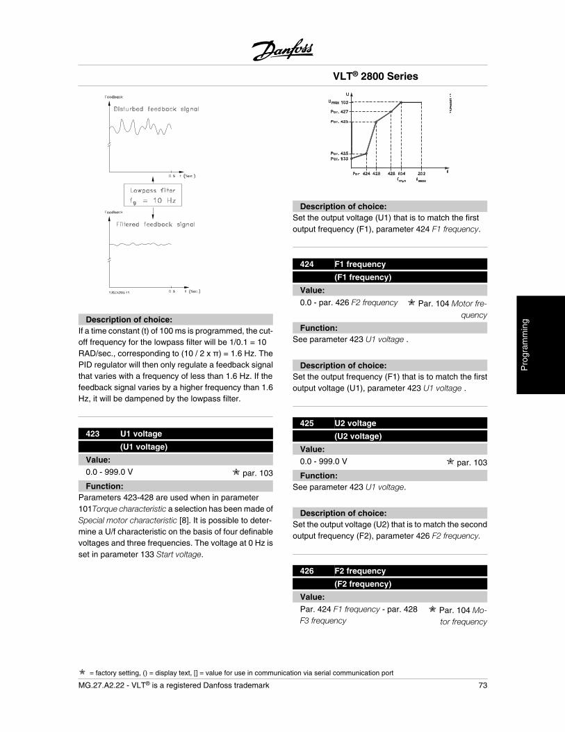
Description of choice:If a time constant (t) of 100 ms is programmed, the cut-off frequency for the lowpass filter will be 1/0.1 = 10RAD/sec., corresponding to (10 / 2 x ) = 1.6 Hz. ThePID regulator will then only regulate a feedback signalthat varies with a frequency of less than 1.6 Hz. If thefeedback signal varies by a higher frequency than 1.6Hz, it will be dampened by the lowpass filter.
423 U1 voltage
(U1 voltage)
Value:0.0 - 999.0 V par. 103
Function:Parameters 423-428 are used when in parameter101Torque characteristic a selection has been made ofSpecial motor characteristic [8]. It is possible to deter-mine a U/f characteristic on the basis of four definablevoltages and three frequencies. The voltage at 0 Hz isset in parameter 133 Start voltage.
Description of choice:Set the output voltage (U1) that is to match the firstoutput frequency (F1), parameter 424 F1 frequency.
424 F1 frequency
(F1 frequency)
Value:0.0 - par. 426 F2 frequency Par. 104 Motor fre-
quency
Function:See parameter 423 U1 voltage .
Description of choice:Set the output frequency (F1) that is to match the firstoutput voltage (U1), parameter 423 U1 voltage .
425 U2 voltage
(U2 voltage)
Value:0.0 - 999.0 V par. 103
Function:See parameter 423 U1 voltage.
Description of choice:Set the output voltage (U2) that is to match the secondoutput frequency (F2), parameter 426 F2 frequency.
426 F2 frequency
(F2 frequency)
Value:Par. 424 F1 frequency - par. 428F3 frequency
Par. 104 Mo-tor frequency
VLT® 2800 Series
= factory setting, () = display text, [] = value for use in communication via serial communication port
MG.27.A2.22 - VLT® is a registered Danfoss trademark 73
Pro
gram
min
g

Function:See parameter 423 U1 voltage.
Description of choice:Set the output frequency (F2) that is to match the sec-ond output voltage (U2), parameter 425 U2 voltage.
427 U3 voltage
(U3 voltage)
Value:0.0-999.0 V par. 103
Function:See parameter 423 U1 voltage.
Description of choice:Set the output voltage (U3) that is to match the thirdoutput frequency (F3), parameter 428 F3 frequency .
428 F3 frequency
(F3 frequency)
Value:Par. 426 F2 frequency - 1000Hz
Par. 104 Motorfrequency
Function:See parameter 423 U1 voltage.
Description of choice:Set the output frequency (F3) that is to match the thirdoutput voltage (U3), parameter 427 U3 voltage .
NOTEParameters 437-444 are only used if inparameter 100 Configuration a selectionhas been made of Process regulation,closed loop. [3].
437 Process PID normal/inverse control
(proc no/inv ctrl)
Value:
Normal (normal) [0]
Inverse (inverse) [1]
Function:It is possible to choose whether the process regulatoris to increase/reduce the output frequency if there is adeviation between the reference/setpoint and the ac-tual process mode.
Description of choice:If the adjustable frequency drive is to reduce the outputfrequency in case the feedback signal increases, se-lect Normal [0].If the adjustable frequency drive is toincrease the output frequency in case the feedbacksignal increases, select Inverse [1].
438 Proces PID anti windup
(proc anti windup)
Value:
Not active (DISABLE) [0]
Active (ENABLE) [1]
Function:It is possible to select whether the process regulator isto continue regulating on a deviation even if it is notpossible to increase/reduce the output frequency.
Description of choice:The factory setting is Enable [1], which means that theintegration link is initialised in relation to the actual out-put frequency if either the current limit, the voltage limitor the max./min. frequency has been reached. Theprocess regulator will not engage again until either theerror is zero or its sign has changed. Select Disable [0]if the integrator is to continue integrating on the devi-ation, even if it is not possible to remove the fault bysuch control.
NOTEIf Disable [0] is selected, it will mean thatwhen the deviation changes its sign, theintegrator will first have to integrate downfrom the level obtained as a result of theformer error, before any change in outputfrequency occurs.
VLT® 2800 Series
= factory setting, () = display text, [] = value for use in communication via serial communication port
74 MG.27.A2.22 - VLT® is a registered Danfoss trademark
439 Process PID start frequency
(PROC START VALUE)
Value:fMIN - fMAX (pa-rameter201/202)
Par. 201 Output frequency, lowlimit, fMIN
Function:When the start signal comes, the adjustable frequencydrive will react in the form of Open loop and will notchange to Closed loop until the programmed start fre-quency is reached. This makes it possible to set afrequency that corresponds to the speed at which theprocess normally runs, which will enable the requiredprocess conditions to be reached sooner.
Description of choice:Set the required start frequency.
NOTEIf the adjustable frequency drive is runninga the current limit before the required startfrequency is obtained, the process regu-lator will not be activated. For the regulatorto be activated anyway, the start frequen-cy must be lower to the required outputfrequency. This can be done during oper-ation.
440 Proces PID proportioanl gain
(PROC. PROP. GAIN)
Value:0.0 - 10.00 0.01
Function:The proportional gain indicates the number of timesthe deviation between the setpoint and the feedbacksignal is to be applied.
Description of choice:Quick regulation is obtained by a high gain, but if thegain is too high, the process may become unstable dueto overshoot.
441 Process PID integration time
(PROC. INTEGR. T.)
Value:0.01 - 9999.99 (OFF) OFF
Function:The integrator provides an increasing gain at a con-stant error between the reference/setpoint and thefeedback signal. The greater the error, the quicker theintegrator frequency contribution will increase.The in-tegral time is the time needed by the integrator to makethe same change as the proportional gain.
Description of choice:Quick regulation is obtained at a short integral time.However, this time may become too short, which canmake the process unstable due to overswing. If the in-tegral time is long, major deviations from the requiredsetpoint may occur, since the process regulator willtake a long time to regulate in relation to a given error.
442 Process PID differentiation time
(PROC. DIFF. time)
Value:0.00 (OFF) - 10.00 sec. 0.00 sec.
Function:The differentiator does not react to a constant error. Itonly makes a gain when an error changes. The quickerthe deviation changes, the stronger the gain from thedifferentiator. The gain is proportional to the speed atwhich the deviation changes.
Description of choice:Quick regulation is obtained with a long differentiationtime. However, this time may become too long, whichcan make the process unstable due to overswing.
443 Process PID diff. gain limit
(PROC. DIFF.GAIN)
Value:5.0 - 50.0 5.0
VLT® 2800 Series
= factory setting, () = display text, [] = value for use in communication via serial communication port
MG.27.A2.22 - VLT® is a registered Danfoss trademark 75
Pro
gram
min
g
Function:It is possible to set a limit for the differentiator gain. Thedifferentiator gain will increase if there are fastchanges, which is why it can be beneficial to limit thisgain. Thereby a pure differentiator gain is obtained atslow changes and a constant differentiator gain wherequick changes to the deviation occur.
Description of choice:Select a differentiator gain limit as required.
444 Process PID lowpass filter time
(proc filter time)
Value:0.02 - 10.00 0.02
Function:Noise in the feedback signal is dampened by a firstorder lowpass filter to reduce the noise's impact on theprocess regulation. This can be an advantage e.g. ifthere is a lot of noise on the signal.
Description of choice:Select the required time constant (t). If a time constant(t) of 0.1 s is programmed, the cut-off frequency for thelowpass filter will be 1/0.1 = 10 RAD/sec., correspond-ing to (10 / 2 x ) = 1.6 Hz. The process regulator willthus only regulate a feedback signal that varies by afrequency lower than 1.6 Hz. If the feedback signalvaries by a higher frequency than 1.6 Hz, it will bedampened by the lowpass filter.
445 Flying start
(flyingstart)
Value:
Off (DISABLE) [0]
OK - same direction(OK-same direction) [1]
OK - both directions(OK-both directions) [2]
DC brake and start(DC-BRAKE BEF. START) [3]
Function:This function makes it possible to 'catch' a rotatingmotor shaft, which is no longer controlled by the ad-justable frequency drive, e.g. because of a mains drop-out. The function is activated each time a startcommand is enabled. For the adjustable frequencydrive to be able to 'catch' the rotating motor shaft, themotor speed must be lower than the frequency thatcorresponds to the frequency in parameter 202 Outputfrequency, high limit, f MAX .
Description of choice:Select Disable [0] if this function is not required.
Select OK - same direction [1] if the motor shaft is onlyable to rotate in the same direction when cutting in. OK- same direction [1] should be selected if in parameter200 Output frequency range a selection has been ofClockwise only .
Select OK - both directions [2] if the motor is able torotate in both directions when cutting in.
Select DC brake and start [3] if the adjustable frequen-cy drive is to be able to brake the motor using the DCbrake first, followed by start. It is assumed that param-eters 126-127/132 DC brake are enabled. In the caseof higher 'Windmilling' (rotating motor) effects, the ad-justable frequency drive is not able to 'catch' a rotatingmotor without selecting DC brake and start .
Limitations:
- Too low inertia will lead to load acceleration,which can be dangerous or prevent correctcatching of a rotating motor. Use the DCbrake instead.
- If the load is driven, e.g. by 'Windmilling' (ro-tating motor) effects, the unit may cut outbecause of overvoltage.
- Flying start does not work at lower valuesthan 250 rpm.
451 Speed PID feedforward factor
(feedforward fact)
Value:0 - 500 % 100 %
VLT® 2800 Series
= factory setting, () = display text, [] = value for use in communication via serial communication port
76 MG.27.A2.22 - VLT® is a registered Danfoss trademark
Function:This parameter is only active if in parameter 100 Con-figuration the selection made is Speed regulation,closed loop. The FF function sends a larger or smallerpart of the reference signal outside the PID controllerin such a way that the PID controller only has an influ-ence on part of the control signal. Any change to theset point will thus have a direct effect on the motorspeed. The FF factor provides high dynamism whenchanging the set point and less overswing.
Description of choice:The required % value can be selected in the interval f
MIN - fMAX. Values over 100 % are used if the set pointvariations are only small.
452 Controller range
(pid contr. range)
Value:0 - 200 % 10 %
Function:This parameter is only active if Speed regulation,closed-loop is made in parameter 100 Configuration.The controller range (bandwidth) limits the output fromthe PID controller as a % of motor frequency fM,N.
Description of choice:The required % value can be selected for motor fre-quency fM,N. If the controller range is reduced, thespeed variations will be less during initial tuning.
455 Frequency range monitor
(MON. FREQ. RANGE)
Value:
Disable [0]
Enable [1]
Function:This parameter is used if warning 33 Out of frequencyrange must be turned off in the display in process con-trol closed-loop. This parameter does not affect theextended status word.
Description of choice:Select Enable [1] to enable the readout in the displayif warning 33 Out of frequency range occurs. SelectDisable [0] to disable the readout in the display if warn-ing 33 Out of frequency range occurs.
456 Brake Voltage Reduce
(BRAKE VOL REDUCE)
Value:0 - 25 V if 200 V device 0
0 - 50 V if 400 V device 0
Function:The user sets the voltage by which the level for resistorbraking is reduced. It is only active when resistor inparameter 400 is selected.
Description of choice:The greater the reduction value, the faster the reactionto a generator overload. Should only be used if thereare problems with overvoltage in the intermediate cir-cuit.
457 Phase loss function
(PHASE LOSS FUNCT)
Value:
Trip (TRIP) [0]
Autoderate & warning (AUTODERATE &WARNING) [1]
Warning (WARNING) [2]
Function:Select the function which is to be activated if the mainsimbalance becomes too high or if a phase is missing.
Description of choice:At Trip [0] the adjustable frequency drive will stop themotor within a few seconds (depending on drive size).If Autoderate & warning [1] is selected, the drive willexport a warning and reduce the output current to 50% of IVLT,N to maintain operation.At Warning [2] only a warning will be exported when amains failure occurs, but in severe cases, other ex-treme conditions might result in a trip.
VLT® 2800 Series
= factory setting, () = display text, [] = value for use in communication via serial communication port
MG.27.A2.22 - VLT® is a registered Danfoss trademark 77
Pro
gram
min
g
NOTEIf Warning has been selected, the life ex-pectancy of the drive will be reduced whenthe mains failure persists.
461 Feedback conversion
(FEEDBACK CONV.)
Value:
Linear (LINEAR) [0]
Square root (SQUARE ROOT) [1]
Function:In this parameter, a function is selected which convertsa connected feedback signal from the process to afeedback value that equals the square root of the con-nected signal. For example, this is used when flow(volume) regulation is required on the basis of pres-sure as feedback signal (flow = constant x
pressure ). This conversion makes it possible to setthe reference in such a way that there is a linear con-nection between the reference and the flow required.
Description of choice:If Linear [0] is selected, the feedback signal and thefeedback value will be proportional. If Square root [1]is selected, the adjustable frequency drive translatesthe feedback signal to a squared feedback value.
VLT® 2800 Series
78 MG.27.A2.22 - VLT® is a registered Danfoss trademark
Enhanced Sleep Mode
The enhanced sleep mode has been developed towork under all conditions and to overcome problemswhen using pumps with flat pump curves, or whensuction pressure varies. Enhanced sleep mode pro-vides excellent control for shutting down the pump atlow-flow, thus saving energy.
If operating with constant pressure control in the SYS-TEM, for instance a drop in the suction pressure willlead to an increase in frequency to maintain pressure.Consequently there is a situation, where the frequencywill vary independent of the flow. This can lead to in-appropriate activation of sleep mode or wake-up of theadjustable frequency drive.
Flat pump curves leads to a situation where there willbe little or no change in frequency in response to flowvariation. Consequently, the adjustable frequencydrive might not reach the sleep frequency when settingit at a low value.
Enhanced sleep mode is based on power/frequencymonitoring and works in closed loop only. Stop due tothe enhanced sleep mode function is initiated underthe following conditions:
• Power consumption is below the no/low flowpower curve and stays there for a certain time(parameter 462 Enhanced sleep mode timer)or
• The pressure feedback is above the refer-ence when running at minimum speed andstays there for a certain time (parameter 462Enhanced sleep mode timer).
If the feedback pressure falls below the wakeup pres-sure (Parameter 464 Wakeup pressure), the adjustablefrequency drive restarts the motor.
Dry Run Detection
For most pumps, especially submersible bore-holepumps, it must be assured that the pump is stopped incase of dry run. This is assured by the Dry run detec-tion feature.
How Does It Work?Dry run detection is based on power/frequency moni-toring and works in both closed and open loop.
Stop (trip) due to dry run is initiated under followingconditions:Closed loop:
• The adjustable frequency drive is running atmaximum frequency (parameter 202 Outputfrequency high limit, fMAX) and
• Feedback is below minimum reference (pa-rameter 204 Minimum reference, Ref,MIN) and
• Power consumption is below the no/low flowpower curve for a certain time (parameter470 Dry run time out)
Open loop:• Whenever the power consumption is below
the no/low flow power curve for a certain time(parameter 470 Dry run time out) the adjust-able frequency drive will trip.
The adjustable frequency drive can be set up for eithermanual or automatic restart after stop (parameters 405Reset function and 406 Automatic restart time).
• Enhanced Sleep Mode and Dry Run Detec-tion can be enabled and disabled independ-ently. This is done in parameter 462Enhanced sleep mode timer and parameter470 Dry run timeout.
Centrifugal pumps with radial impellers show a clearone-to-one relation between power consumption andflow, which is utilized to detect a no or low flow situa-tion.It is only necessary to enter two sets of values for pow-er and frequency (min and max) at no or low flow. Theadjustable frequency drive then automatically calcu-lates all data in-between those two sets of values andgenerates the no/low flow power curve.If the power consumption falls below the power curve,the adjustable frequency drive enters Sleep-mode ortrips due to dry run, depending on the configuration.
VLT® 2800 Series
MG.27.A2.22 - VLT® is a registered Danfoss trademark 79
Pro
gram
min
g
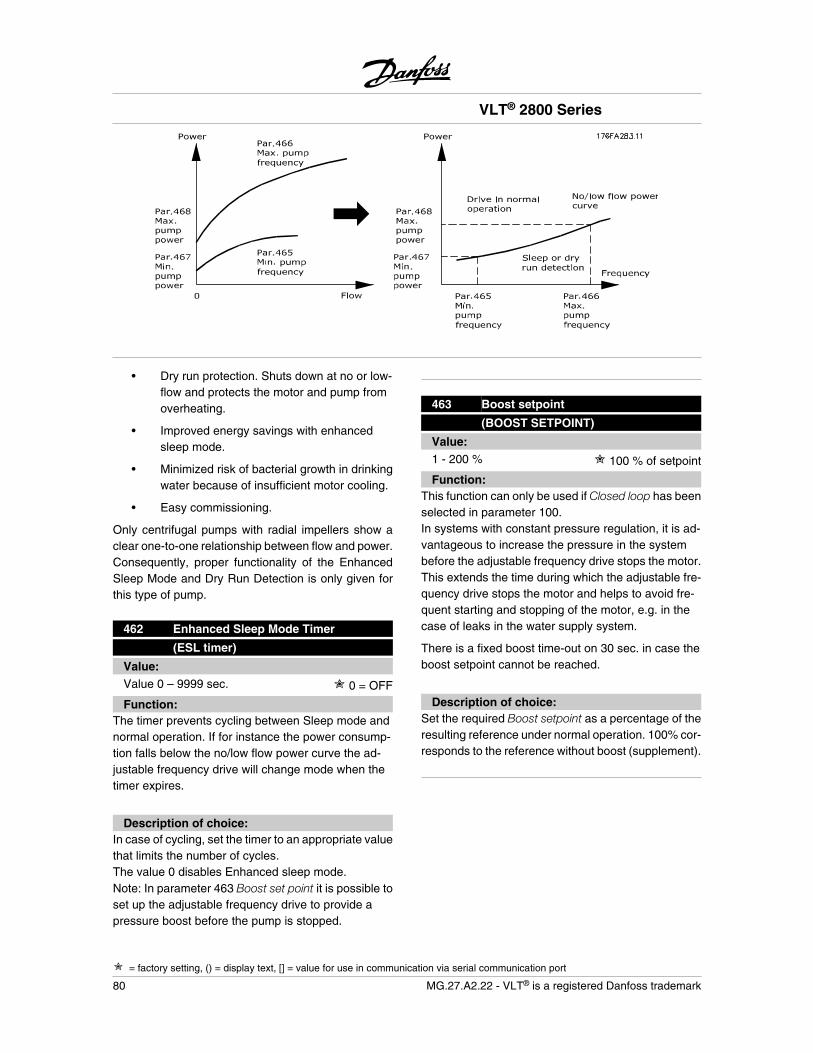
• Dry run protection. Shuts down at no or low-flow and protects the motor and pump fromoverheating.
• Improved energy savings with enhancedsleep mode.
• Minimized risk of bacterial growth in drinkingwater because of insufficient motor cooling.
• Easy commissioning.
Only centrifugal pumps with radial impellers show aclear one-to-one relationship between flow and power.Consequently, proper functionality of the EnhancedSleep Mode and Dry Run Detection is only given forthis type of pump.
462 Enhanced Sleep Mode Timer
(ESL timer)
Value:Value 0 – 9999 sec. 0 = OFF
Function:The timer prevents cycling between Sleep mode andnormal operation. If for instance the power consump-tion falls below the no/low flow power curve the ad-justable frequency drive will change mode when thetimer expires.
Description of choice:In case of cycling, set the timer to an appropriate valuethat limits the number of cycles.The value 0 disables Enhanced sleep mode.Note: In parameter 463 Boost set point it is possible toset up the adjustable frequency drive to provide apressure boost before the pump is stopped.
463 Boost setpoint
(BOOST SETPOINT)
Value:1 - 200 % 100 % of setpoint
Function:This function can only be used if Closed loop has beenselected in parameter 100.In systems with constant pressure regulation, it is ad-vantageous to increase the pressure in the systembefore the adjustable frequency drive stops the motor.This extends the time during which the adjustable fre-quency drive stops the motor and helps to avoid fre-quent starting and stopping of the motor, e.g. in thecase of leaks in the water supply system.
There is a fixed boost time-out on 30 sec. in case theboost setpoint cannot be reached.
Description of choice:Set the required Boost setpoint as a percentage of theresulting reference under normal operation. 100% cor-responds to the reference without boost (supplement).
VLT® 2800 Series
= factory setting, () = display text, [] = value for use in communication via serial communication port
80 MG.27.A2.22 - VLT® is a registered Danfoss trademark
464 Wakeup Pressure
(Wakeup Pressure)
Value:Par. 204 RefMIN – par. 215 - 218 Setpoint 0
Function:When in Sleep mode the adjustable frequency drivewill wake up when the pressure is below the Wakeuppressure for the time set in parameter 462 Enhancedsleep mode timer.
Description of choice:Set an appropriate value for the system. The unit is setin parameter 416.
465 Minimum pump frequency
(Pump min. freq.)
Value:Value par. 201 fMIN – par. 202 fMAX (Hz) 20
Function:This parameter is linked to parameter 467 MinimumPower and is used for no/low-flow power curve.
Description of choice:Enter a value equal or close to the desired minimumfrequency set in parameter 201 Output frequency lowlimit, fMIN . Please note that the extension of the no/low-flow power curve is limited by parameters 201 and 202,and not by parameters 465 and 466.
466 Maximum Pump Frequency
(Pump max. freq)
Value:Value par. 201 fMIN - par. 202 fMAX (Hz) 50
Function:This parameter is linked to parameter 468 Maximumpump power and is used for the no/low-flow powercurve.
Description of choice:Enter a value equal or close to the desired maximumfrequency set in parameter 202 Output frequency highlimit, fMAX .
467 Minimum Pump Power
(Min. pump power)
Value:0–500.000 W 0
Function:The associated power consumption at the frequencyentered in parameter 465 Minimum pump frequency.
Description of choice:Enter the no/low-flow power reading at minimum pumpfrequency entered in parameter 465.
Depending on pump size or curve, select W or kW inpar. 009 index [32] and [8] for fine tuning.
468 Maximum Pump Power
(Max. pump power)
Value:0–500.000 W 0
Function:The associated power consumption at the frequencyentered in parameter 466 Minimum pump frequency.
Description of choice:Enter the no/low-flow power reading at maximumpump frequency entered in parameter 466.
Depending on pump size or curve, select W or kW inpar. 009 index [32] and [8] for fine tuning.
469 No Flow Power Compensation
(NF power comp)
Value:0.01 - 2 1.2
Function:This function is used for an off-set of the no/low-flowpower curve, which can be used as a safety factor orfor fine tuning the system.
Description of choice:Description The factor is multiplied to the power val-ues. E.g., 1.2 will increase the power value with 1.2over the whole frequency range.
VLT® 2800 Series
= factory setting, () = display text, [] = value for use in communication via serial communication port
MG.27.A2.22 - VLT® is a registered Danfoss trademark 81
Pro
gram
min
g
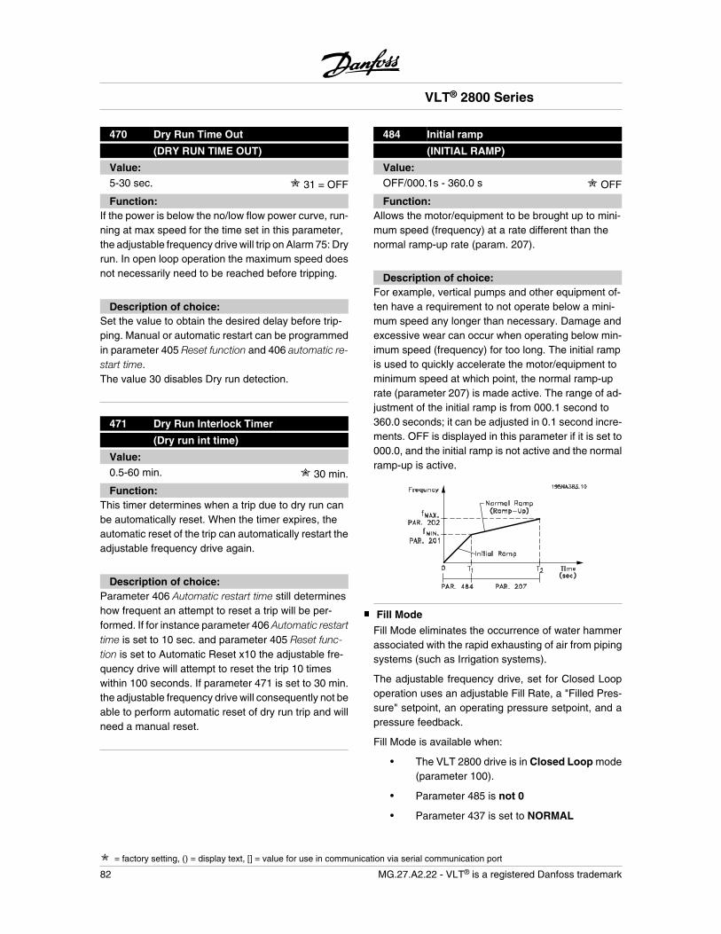
470 Dry Run Time Out
(DRY RUN TIME OUT)
Value:5-30 sec. 31 = OFF
Function:If the power is below the no/low flow power curve, run-ning at max speed for the time set in this parameter,the adjustable frequency drive will trip on Alarm 75: Dryrun. In open loop operation the maximum speed doesnot necessarily need to be reached before tripping.
Description of choice:Set the value to obtain the desired delay before trip-ping. Manual or automatic restart can be programmedin parameter 405 Reset function and 406 automatic re-start time.The value 30 disables Dry run detection.
471 Dry Run Interlock Timer
(Dry run int time)
Value:0.5-60 min. 30 min.
Function:This timer determines when a trip due to dry run canbe automatically reset. When the timer expires, theautomatic reset of the trip can automatically restart theadjustable frequency drive again.
Description of choice:Parameter 406 Automatic restart time still determineshow frequent an attempt to reset a trip will be per-formed. If for instance parameter 406 Automatic restarttime is set to 10 sec. and parameter 405 Reset func-tion is set to Automatic Reset x10 the adjustable fre-quency drive will attempt to reset the trip 10 timeswithin 100 seconds. If parameter 471 is set to 30 min.the adjustable frequency drive will consequently not beable to perform automatic reset of dry run trip and willneed a manual reset.
484 Initial ramp
(INITIAL RAMP)
Value:OFF/000.1s - 360.0 s OFF
Function:Allows the motor/equipment to be brought up to mini-mum speed (frequency) at a rate different than thenormal ramp-up rate (param. 207).
Description of choice:For example, vertical pumps and other equipment of-ten have a requirement to not operate below a mini-mum speed any longer than necessary. Damage andexcessive wear can occur when operating below min-imum speed (frequency) for too long. The initial rampis used to quickly accelerate the motor/equipment tominimum speed at which point, the normal ramp-uprate (parameter 207) is made active. The range of ad-justment of the initial ramp is from 000.1 second to360.0 seconds; it can be adjusted in 0.1 second incre-ments. OFF is displayed in this parameter if it is set to000.0, and the initial ramp is not active and the normalramp-up is active.
Fill Mode
Fill Mode eliminates the occurrence of water hammerassociated with the rapid exhausting of air from pipingsystems (such as Irrigation systems).
The adjustable frequency drive, set for Closed Loopoperation uses an adjustable Fill Rate, a "Filled Pres-sure" setpoint, an operating pressure setpoint, and apressure feedback.
Fill Mode is available when:
• The VLT 2800 drive is in Closed Loop mode(parameter 100).
• Parameter 485 is not 0
• Parameter 437 is set to NORMAL
VLT® 2800 Series
= factory setting, () = display text, [] = value for use in communication via serial communication port
82 MG.27.A2.22 - VLT® is a registered Danfoss trademark
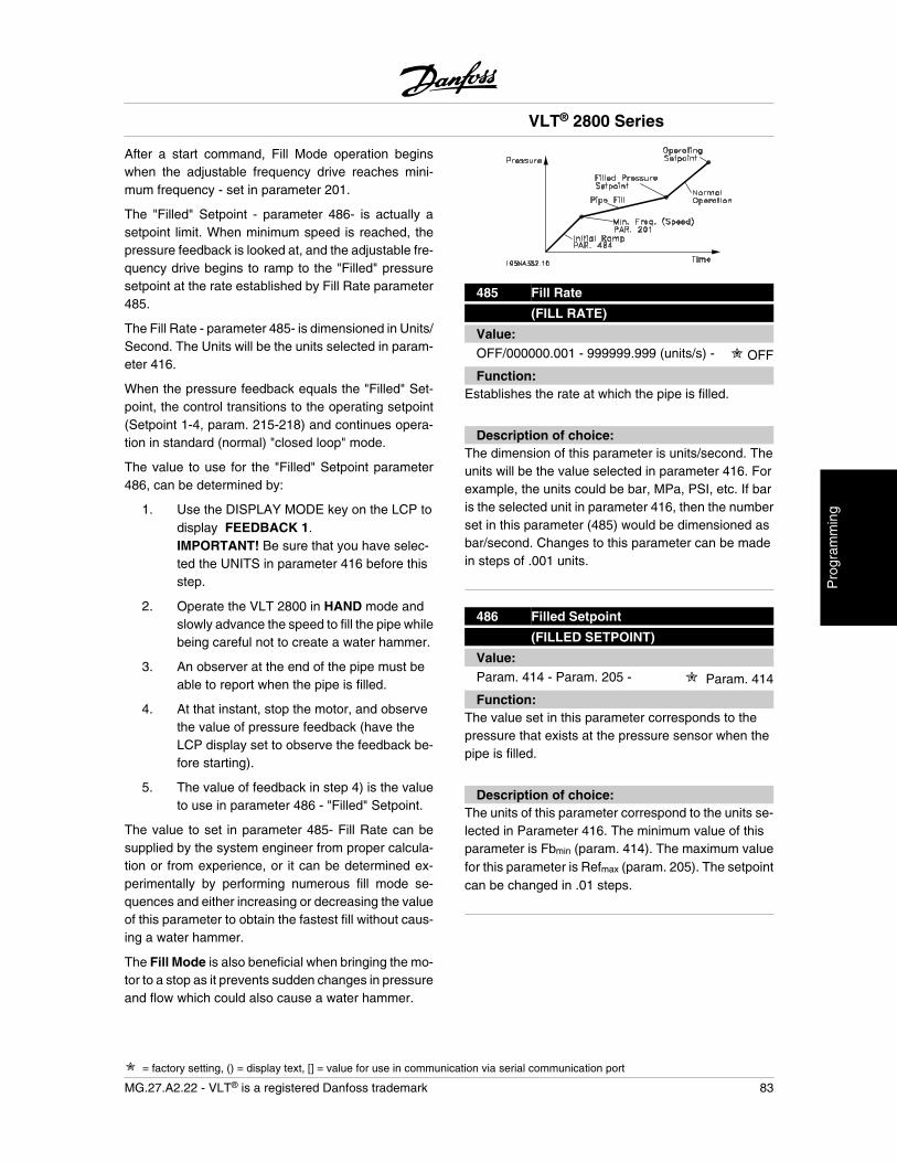
After a start command, Fill Mode operation beginswhen the adjustable frequency drive reaches mini-mum frequency - set in parameter 201.
The "Filled" Setpoint - parameter 486- is actually asetpoint limit. When minimum speed is reached, thepressure feedback is looked at, and the adjustable fre-quency drive begins to ramp to the "Filled" pressuresetpoint at the rate established by Fill Rate parameter485.
The Fill Rate - parameter 485- is dimensioned in Units/Second. The Units will be the units selected in param-eter 416.
When the pressure feedback equals the "Filled" Set-point, the control transitions to the operating setpoint(Setpoint 1-4, param. 215-218) and continues opera-tion in standard (normal) "closed loop" mode.
The value to use for the "Filled" Setpoint parameter486, can be determined by:
1. Use the DISPLAY MODE key on the LCP todisplay FEEDBACK 1.IMPORTANT! Be sure that you have selec-ted the UNITS in parameter 416 before thisstep.
2. Operate the VLT 2800 in HAND mode andslowly advance the speed to fill the pipe whilebeing careful not to create a water hammer.
3. An observer at the end of the pipe must beable to report when the pipe is filled.
4. At that instant, stop the motor, and observethe value of pressure feedback (have theLCP display set to observe the feedback be-fore starting).
5. The value of feedback in step 4) is the valueto use in parameter 486 - "Filled" Setpoint.
The value to set in parameter 485- Fill Rate can besupplied by the system engineer from proper calcula-tion or from experience, or it can be determined ex-perimentally by performing numerous fill mode se-quences and either increasing or decreasing the valueof this parameter to obtain the fastest fill without caus-ing a water hammer.
The Fill Mode is also beneficial when bringing the mo-tor to a stop as it prevents sudden changes in pressureand flow which could also cause a water hammer.
485 Fill Rate
(FILL RATE)
Value:OFF/000000.001 - 999999.999 (units/s) - OFF
Function:Establishes the rate at which the pipe is filled.
Description of choice:The dimension of this parameter is units/second. Theunits will be the value selected in parameter 416. Forexample, the units could be bar, MPa, PSI, etc. If baris the selected unit in parameter 416, then the numberset in this parameter (485) would be dimensioned asbar/second. Changes to this parameter can be madein steps of .001 units.
486 Filled Setpoint
(FILLED SETPOINT)
Value:Param. 414 - Param. 205 - Param. 414
Function:The value set in this parameter corresponds to thepressure that exists at the pressure sensor when thepipe is filled.
Description of choice:The units of this parameter correspond to the units se-lected in Parameter 416. The minimum value of thisparameter is Fbmin (param. 414). The maximum valuefor this parameter is Refmax (param. 205). The setpointcan be changed in .01 steps.
VLT® 2800 Series
= factory setting, () = display text, [] = value for use in communication via serial communication port
MG.27.A2.22 - VLT® is a registered Danfoss trademark 83
Pro
gram
min
g
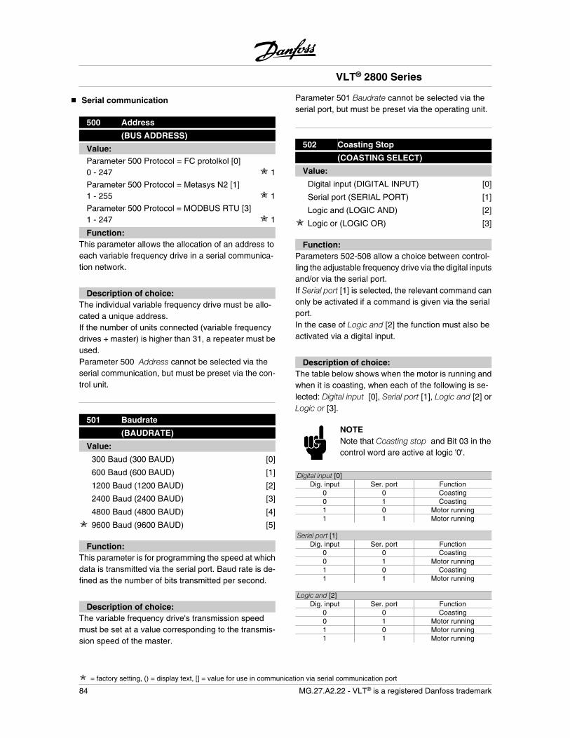
Serial communication
500 Address
(BUS ADDRESS)
Value:Parameter 500 Protocol = FC protolkol [0]0 - 247 1
Parameter 500 Protocol = Metasys N2 [1]1 - 255 1
Parameter 500 Protocol = MODBUS RTU [3]1 - 247 1
Function:This parameter allows the allocation of an address toeach variable frequency drive in a serial communica-tion network.
Description of choice:The individual variable frequency drive must be allo-cated a unique address.If the number of units connected (variable frequencydrives + master) is higher than 31, a repeater must beused.Parameter 500 Address cannot be selected via theserial communication, but must be preset via the con-trol unit.
501 Baudrate
(BAUDRATE)
Value:
300 Baud (300 BAUD) [0]
600 Baud (600 BAUD) [1]
1200 Baud (1200 BAUD) [2]
2400 Baud (2400 BAUD) [3]
4800 Baud (4800 BAUD) [4]
9600 Baud (9600 BAUD) [5]
Function:This parameter is for programming the speed at whichdata is transmitted via the serial port. Baud rate is de-fined as the number of bits transmitted per second.
Description of choice:The variable frequency drive's transmission speedmust be set at a value corresponding to the transmis-sion speed of the master.
Parameter 501 Baudrate cannot be selected via theserial port, but must be preset via the operating unit.
502 Coasting Stop
(COASTING SELECT)
Value:
Digital input (DIGITAL INPUT) [0]
Serial port (SERIAL PORT) [1]
Logic and (LOGIC AND) [2]
Logic or (LOGIC OR) [3]
Function:Parameters 502-508 allow a choice between control-ling the adjustable frequency drive via the digital inputsand/or via the serial port.If Serial port [1] is selected, the relevant command canonly be activated if a command is given via the serialport.In the case of Logic and [2] the function must also beactivated via a digital input.
Description of choice:The table below shows when the motor is running andwhen it is coasting, when each of the following is se-lected: Digital input [0], Serial port [1], Logic and [2] orLogic or [3].
NOTENote that Coasting stop and Bit 03 in thecontrol word are active at logic '0'.
Digital input [0]Dig. input Ser. port Function
0 0 Coasting0 1 Coasting1 0 Motor running1 1 Motor running
Serial port [1]Dig. input Ser. port Function
0 0 Coasting0 1 Motor running1 0 Coasting1 1 Motor running
Logic and [2]Dig. input Ser. port Function
0 0 Coasting0 1 Motor running1 0 Motor running1 1 Motor running
VLT® 2800 Series
= factory setting, () = display text, [] = value for use in communication via serial communication port
84 MG.27.A2.22 - VLT® is a registered Danfoss trademark
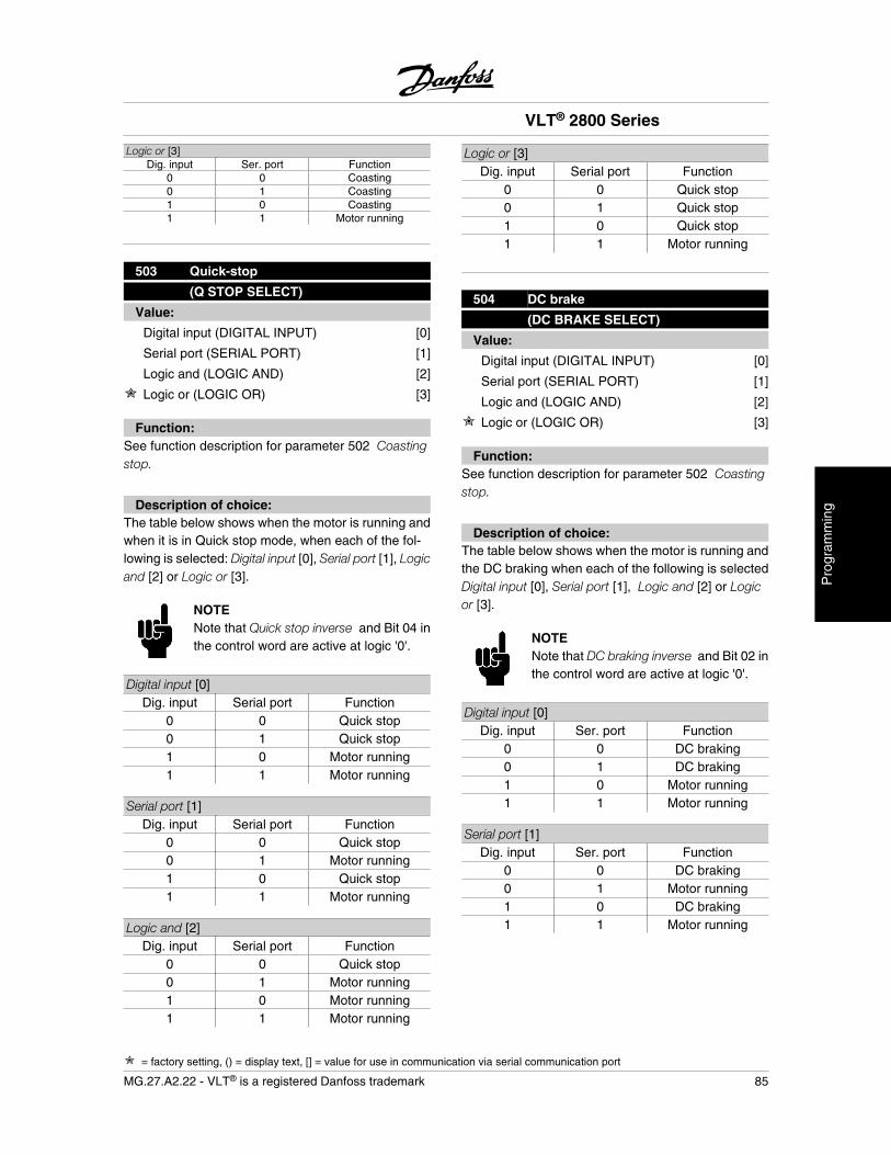
Logic or [3]Dig. input Ser. port Function
0 0 Coasting0 1 Coasting1 0 Coasting1 1 Motor running
503 Quick-stop
(Q STOP SELECT)
Value:
Digital input (DIGITAL INPUT) [0]
Serial port (SERIAL PORT) [1]
Logic and (LOGIC AND) [2]
Logic or (LOGIC OR) [3]
Function:See function description for parameter 502 Coastingstop.
Description of choice:The table below shows when the motor is running andwhen it is in Quick stop mode, when each of the fol-lowing is selected: Digital input [0], Serial port [1], Logicand [2] or Logic or [3].
NOTENote that Quick stop inverse and Bit 04 inthe control word are active at logic '0'.
Digital input [0]Dig. input Serial port Function
0 0 Quick stop0 1 Quick stop1 0 Motor running1 1 Motor running
Serial port [1]Dig. input Serial port Function
0 0 Quick stop0 1 Motor running1 0 Quick stop1 1 Motor running
Logic and [2]Dig. input Serial port Function
0 0 Quick stop0 1 Motor running1 0 Motor running1 1 Motor running
Logic or [3]Dig. input Serial port Function
0 0 Quick stop0 1 Quick stop1 0 Quick stop1 1 Motor running
504 DC brake
(DC BRAKE SELECT)
Value:
Digital input (DIGITAL INPUT) [0]
Serial port (SERIAL PORT) [1]
Logic and (LOGIC AND) [2]
Logic or (LOGIC OR) [3]
Function:See function description for parameter 502 Coastingstop.
Description of choice:The table below shows when the motor is running andthe DC braking when each of the following is selectedDigital input [0], Serial port [1], Logic and [2] or Logicor [3].
NOTENote that DC braking inverse and Bit 02 inthe control word are active at logic '0'.
Digital input [0]Dig. input Ser. port Function
0 0 DC braking0 1 DC braking1 0 Motor running1 1 Motor running
Serial port [1]Dig. input Ser. port Function
0 0 DC braking0 1 Motor running1 0 DC braking1 1 Motor running
VLT® 2800 Series
= factory setting, () = display text, [] = value for use in communication via serial communication port
MG.27.A2.22 - VLT® is a registered Danfoss trademark 85
Pro
gram
min
g
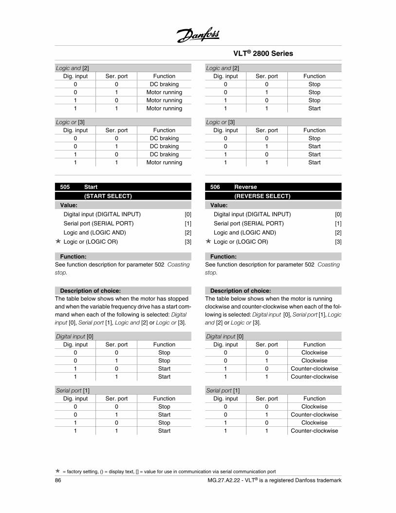
Logic and [2]Dig. input Ser. port Function
0 0 DC braking0 1 Motor running1 0 Motor running1 1 Motor running
Logic or [3]Dig. input Ser. port Function
0 0 DC braking0 1 DC braking1 0 DC braking1 1 Motor running
505 Start
(START SELECT)
Value:
Digital input (DIGITAL INPUT) [0]
Serial port (SERIAL PORT) [1]
Logic and (LOGIC AND) [2]
Logic or (LOGIC OR) [3]
Function:See function description for parameter 502 Coastingstop.
Description of choice:The table below shows when the motor has stoppedand when the variable frequency drive has a start com-mand when each of the following is selected: Digitalinput [0], Serial port [1], Logic and [2] or Logic or [3].
Digital input [0]Dig. input Ser. port Function
0 0 Stop0 1 Stop1 0 Start1 1 Start
Serial port [1]Dig. input Ser. port Function
0 0 Stop0 1 Start1 0 Stop1 1 Start
Logic and [2]Dig. input Ser. port Function
0 0 Stop0 1 Stop1 0 Stop1 1 Start
Logic or [3]Dig. input Ser. port Function
0 0 Stop0 1 Start1 0 Start1 1 Start
506 Reverse
(REVERSE SELECT)
Value:
Digital input (DIGITAL INPUT) [0]
Serial port (SERIAL PORT) [1]
Logic and (LOGIC AND) [2]
Logic or (LOGIC OR) [3]
Function:See function description for parameter 502 Coastingstop.
Description of choice:The table below shows when the motor is runningclockwise and counter-clockwise when each of the fol-lowing is selected: Digital input [0], Serial port [1], Logicand [2] or Logic or [3].
Digital input [0]Dig. input Ser. port Function
0 0 Clockwise0 1 Clockwise1 0 Counter-clockwise1 1 Counter-clockwise
Serial port [1]Dig. input Ser. port Function
0 0 Clockwise0 1 Counter-clockwise1 0 Clockwise1 1 Counter-clockwise
VLT® 2800 Series
= factory setting, () = display text, [] = value for use in communication via serial communication port
86 MG.27.A2.22 - VLT® is a registered Danfoss trademark
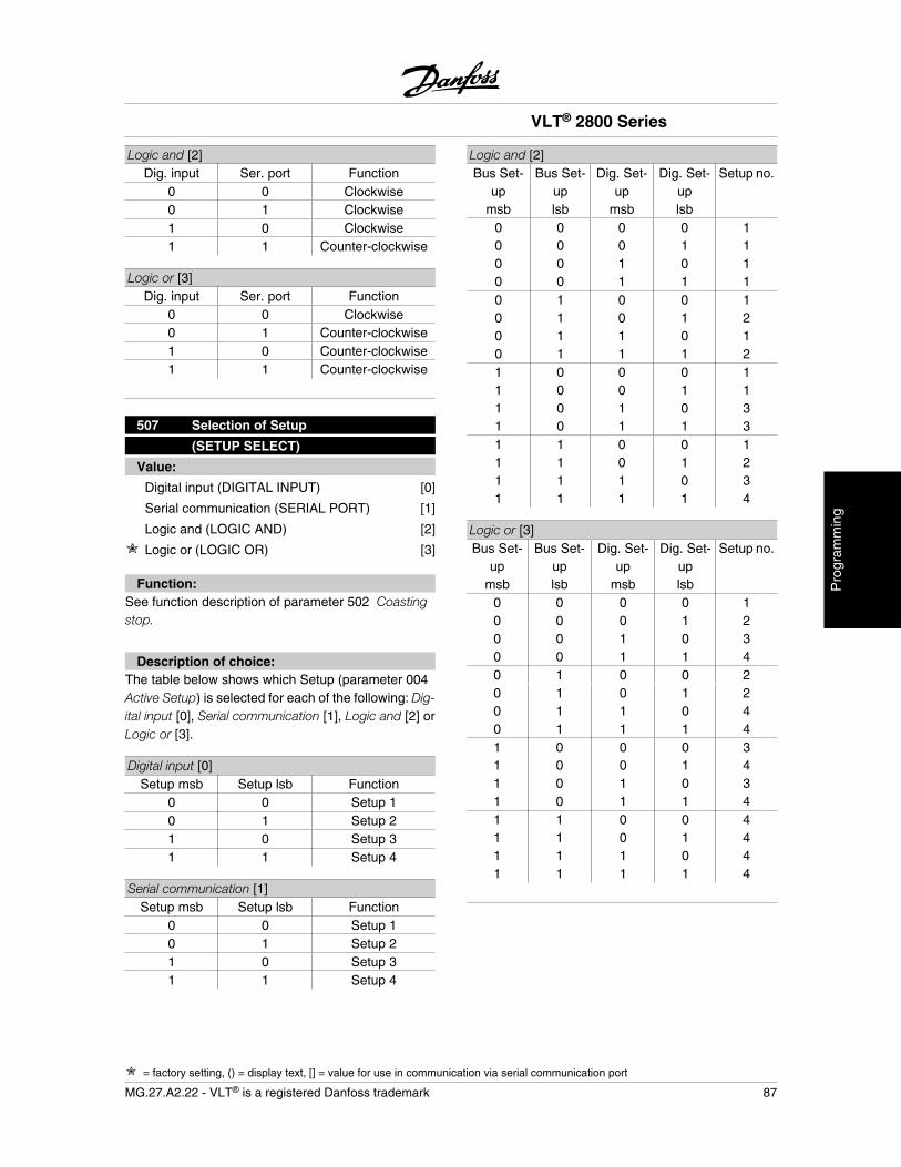
Logic and [2]Dig. input Ser. port Function
0 0 Clockwise0 1 Clockwise1 0 Clockwise1 1 Counter-clockwise
Logic or [3]Dig. input Ser. port Function
0 0 Clockwise0 1 Counter-clockwise1 0 Counter-clockwise1 1 Counter-clockwise
507 Selection of Setup
(SETUP SELECT)
Value:
Digital input (DIGITAL INPUT) [0]
Serial communication (SERIAL PORT) [1]
Logic and (LOGIC AND) [2]
Logic or (LOGIC OR) [3]
Function:See function description of parameter 502 Coastingstop.
Description of choice:The table below shows which Setup (parameter 004Active Setup) is selected for each of the following: Dig-ital input [0], Serial communication [1], Logic and [2] orLogic or [3].
Digital input [0]Setup msb Setup lsb Function
0 0 Setup 10 1 Setup 21 0 Setup 31 1 Setup 4
Serial communication [1]Setup msb Setup lsb Function
0 0 Setup 10 1 Setup 21 0 Setup 31 1 Setup 4
Logic and [2]Bus Set-
upmsb
Bus Set-uplsb
Dig. Set-up
msb
Dig. Set-uplsb
Setup no.
0 0 0 0 10 0 0 1 10 0 1 0 10 0 1 1 10 1 0 0 10 1 0 1 20 1 1 0 10 1 1 1 21 0 0 0 11 0 0 1 11 0 1 0 31 0 1 1 31 1 0 0 11 1 0 1 21 1 1 0 31 1 1 1 4
Logic or [3]Bus Set-
upmsb
Bus Set-uplsb
Dig. Set-up
msb
Dig. Set-uplsb
Setup no.
0 0 0 0 10 0 0 1 20 0 1 0 30 0 1 1 40 1 0 0 20 1 0 1 20 1 1 0 40 1 1 1 41 0 0 0 31 0 0 1 41 0 1 0 31 0 1 1 41 1 0 0 41 1 0 1 41 1 1 0 41 1 1 1 4
VLT® 2800 Series
= factory setting, () = display text, [] = value for use in communication via serial communication port
MG.27.A2.22 - VLT® is a registered Danfoss trademark 87
Pro
gram
min
g

508 Selection of preset ref.
(PRES.REF. SELECT)
Value:
Digital input (DIGITAL INPUT) [0]
Serial comunication (SERIAL PORT) [1]
Logic and (LOGIC AND) [2]
Logic or (LOGIC OR) [3]
Function:See function description of parameter 502 Coastingstop.
Description of choice:Preset references via serial communication are activewhen parameter 512 Telegram profile is set to FC pro-tocol [1].
509 Bus jog 1 (BUS JOG 1 FREQ.)510 Bus jog 2 (BUS JOG 2 FREQ.)
Value:0.0 - par. 202 Output frequency highlimit 10,0 Hz
Function:If parameter 512 Telegram Profile shows the selectionProfidrive [0], two fixed speeds (Jog 1 or Jog 2) can beselected via the serial port.The function is the same as in parameter 213 Jog fre-quency .
Description of choice:Jog frequency fJOG can be selected between 0 Hz andfMAX.
512 Telegram Profile
(Telegram Profile)
Value:
Profidrive (Profidrive) [0]
FC protocol (FC protocol) [1]
Function:It is possible to choose between two different controlword profiles.
Description of choice:Select the desired control word profile.See Serial port for VLT 2800 for further details of con-trol word profiles.
513 Bus time interval
(BUS TIMEOUT TIME)
Value:1 - 99 sec. 1 sec.
Function:In this parameter it is possible to preset the maximumtime expected to elapse between receipt of two con-secutive telegrams. If this time is exceeded, the serialcommunication is assumed to have stopped and thedesired reaction is preset in parameter 514 Bus timeinterval function.
Description of choice:Preset the required time.
514 Bus time interval function
(BUS TIMEOUT FUNC)
Value:
Off (off) [0]
Freeze output frequency (FREEZE OUTPUT) [1]
Stop (STOP) [2]
Jogging (JOGGING) [3]
Max. speed (MAX SPEED) [4]
Stop and trip (STOP AND TRIP) [5]
Function:In this parameter you can select the required reactionfor the variable frequency drive when the preset timein parameter 513 Bus time interval has been excee-ded. If choices [1] to [5] are activated the output relaywill be deactivated.
Description of choice:The output frequency of the variable frequency drivecan be frozen at the present value, stop the motor, befrozen at parameter 213 Jogging frequency, be frozenat parameter 202 Output frequency, high limit fMAX orstop and activate a cut out.
VLT® 2800 Series
= factory setting, () = display text, [] = value for use in communication via serial communication port
88 MG.27.A2.22 - VLT® is a registered Danfoss trademark
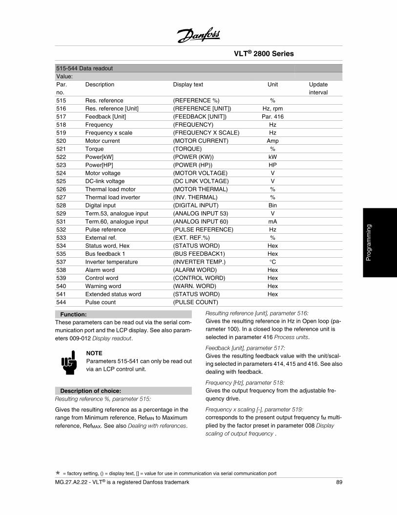
515-544 Data readoutValue:Par.no.
Description Display text Unit Updateinterval
515 Res. reference (REFERENCE %) %516 Res. reference [Unit] (REFERENCE [UNIT]) Hz, rpm517 Feedback [Unit] (FEEDBACK [UNIT]) Par. 416518 Frequency (FREQUENCY) Hz519 Frequency x scale (FREQUENCY X SCALE) Hz520 Motor current (MOTOR CURRENT) Amp521 Torque (TORQUE) %522 Power[kW] (POWER (KW)) kW523 Power[HP] (POWER (HP)) HP524 Motor voltage (MOTOR VOLTAGE) V525 DC-link voltage (DC LINK VOLTAGE) V526 Thermal load motor (MOTOR THERMAL) %527 Thermal load inverter (INV. THERMAL) %528 Digital input (DIGITAL INPUT) Bin529 Term.53, analogue input (ANALOG INPUT 53) V531 Term.60, analogue input (ANALOG INPUT 60) mA532 Pulse reference (PULSE REFERENCE) Hz533 External ref. (EXT. REF.%) %534 Status word, Hex (STATUS WORD) Hex535 Bus feedback 1 (BUS FEEDBACK1) Hex537 Inverter temperature (INVERTER TEMP.) °C538 Alarm word (ALARM WORD) Hex539 Control word (CONTROL WORD) Hex540 Warning word (WARN. WORD) Hex541 Extended status word (STATUS WORD) Hex544 Pulse count (PULSE COUNT)
Function:These parameters can be read out via the serial com-munication port and the LCP display. See also param-eters 009-012 Display readout.
NOTEParameters 515-541 can only be read outvia an LCP control unit.
Description of choice:Resulting reference %, parameter 515:
Gives the resulting reference as a percentage in therange from Minimum reference, RefMIN to Maximumreference, RefMAX. See also Dealing with references.
Resulting reference [unit], parameter 516:Gives the resulting reference in Hz in Open loop (pa-rameter 100). In a closed loop the reference unit isselected in parameter 416 Process units.
Feedback [unit], parameter 517:Gives the resulting feedback value with the unit/scal-ing selected in parameters 414, 415 and 416. See alsodealing with feedback.
Frequency [Hz], parameter 518:Gives the output frequency from the adjustable fre-quency drive.
Frequency x scaling [-], parameter 519:corresponds to the present output frequency fM multi-plied by the factor preset in parameter 008 Displayscaling of output frequency .
VLT® 2800 Series
= factory setting, () = display text, [] = value for use in communication via serial communication port
MG.27.A2.22 - VLT® is a registered Danfoss trademark 89
Pro
gram
min
g
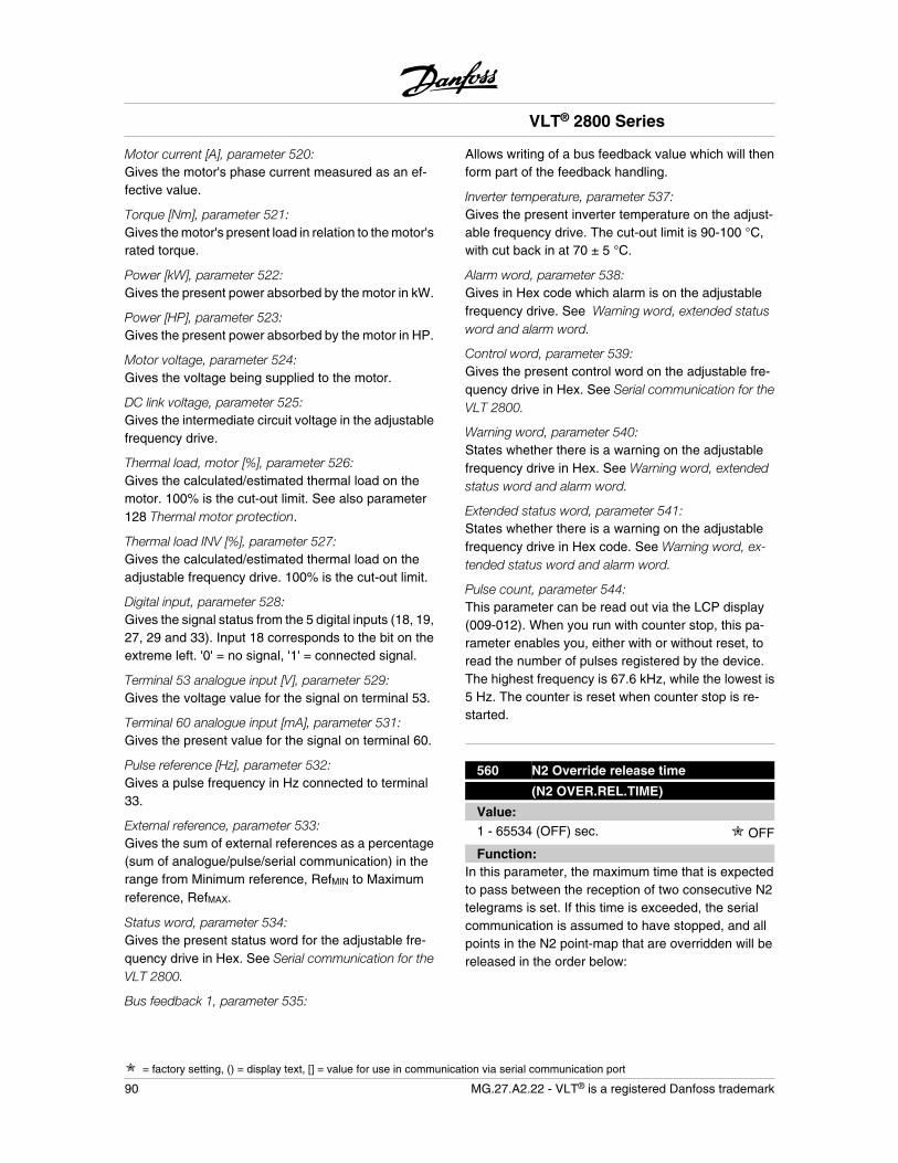
Motor current [A], parameter 520:Gives the motor's phase current measured as an ef-fective value.
Torque [Nm], parameter 521:Gives the motor's present load in relation to the motor'srated torque.
Power [kW], parameter 522:Gives the present power absorbed by the motor in kW.
Power [HP], parameter 523:Gives the present power absorbed by the motor in HP.
Motor voltage, parameter 524:Gives the voltage being supplied to the motor.
DC link voltage, parameter 525:Gives the intermediate circuit voltage in the adjustablefrequency drive.
Thermal load, motor [%], parameter 526:Gives the calculated/estimated thermal load on themotor. 100% is the cut-out limit. See also parameter128 Thermal motor protection.
Thermal load INV [%], parameter 527:Gives the calculated/estimated thermal load on theadjustable frequency drive. 100% is the cut-out limit.
Digital input, parameter 528:Gives the signal status from the 5 digital inputs (18, 19,27, 29 and 33). Input 18 corresponds to the bit on theextreme left. '0' = no signal, '1' = connected signal.
Terminal 53 analogue input [V], parameter 529:Gives the voltage value for the signal on terminal 53.
Terminal 60 analogue input [mA], parameter 531:Gives the present value for the signal on terminal 60.
Pulse reference [Hz], parameter 532:Gives a pulse frequency in Hz connected to terminal33.
External reference, parameter 533:Gives the sum of external references as a percentage(sum of analogue/pulse/serial communication) in therange from Minimum reference, RefMIN to Maximumreference, RefMAX.
Status word, parameter 534:Gives the present status word for the adjustable fre-quency drive in Hex. See Serial communication for theVLT 2800.
Bus feedback 1, parameter 535:
Allows writing of a bus feedback value which will thenform part of the feedback handling.
Inverter temperature, parameter 537:Gives the present inverter temperature on the adjust-able frequency drive. The cut-out limit is 90-100 °C,with cut back in at 70 ± 5 °C.
Alarm word, parameter 538:Gives in Hex code which alarm is on the adjustablefrequency drive. See Warning word, extended statusword and alarm word.
Control word, parameter 539:Gives the present control word on the adjustable fre-quency drive in Hex. See Serial communication for theVLT 2800.
Warning word, parameter 540:States whether there is a warning on the adjustablefrequency drive in Hex. See Warning word, extendedstatus word and alarm word.
Extended status word, parameter 541:States whether there is a warning on the adjustablefrequency drive in Hex code. See Warning word, ex-tended status word and alarm word.
Pulse count, parameter 544:This parameter can be read out via the LCP display(009-012). When you run with counter stop, this pa-rameter enables you, either with or without reset, toread the number of pulses registered by the device.The highest frequency is 67.6 kHz, while the lowest is5 Hz. The counter is reset when counter stop is re-started.
560 N2 Override release time
(N2 OVER.REL.TIME)
Value:1 - 65534 (OFF) sec. OFF
Function:In this parameter, the maximum time that is expectedto pass between the reception of two consecutive N2telegrams is set. If this time is exceeded, the serialcommunication is assumed to have stopped, and allpoints in the N2 point-map that are overridden will bereleased in the order below:
VLT® 2800 Series
= factory setting, () = display text, [] = value for use in communication via serial communication port
90 MG.27.A2.22 - VLT® is a registered Danfoss trademark
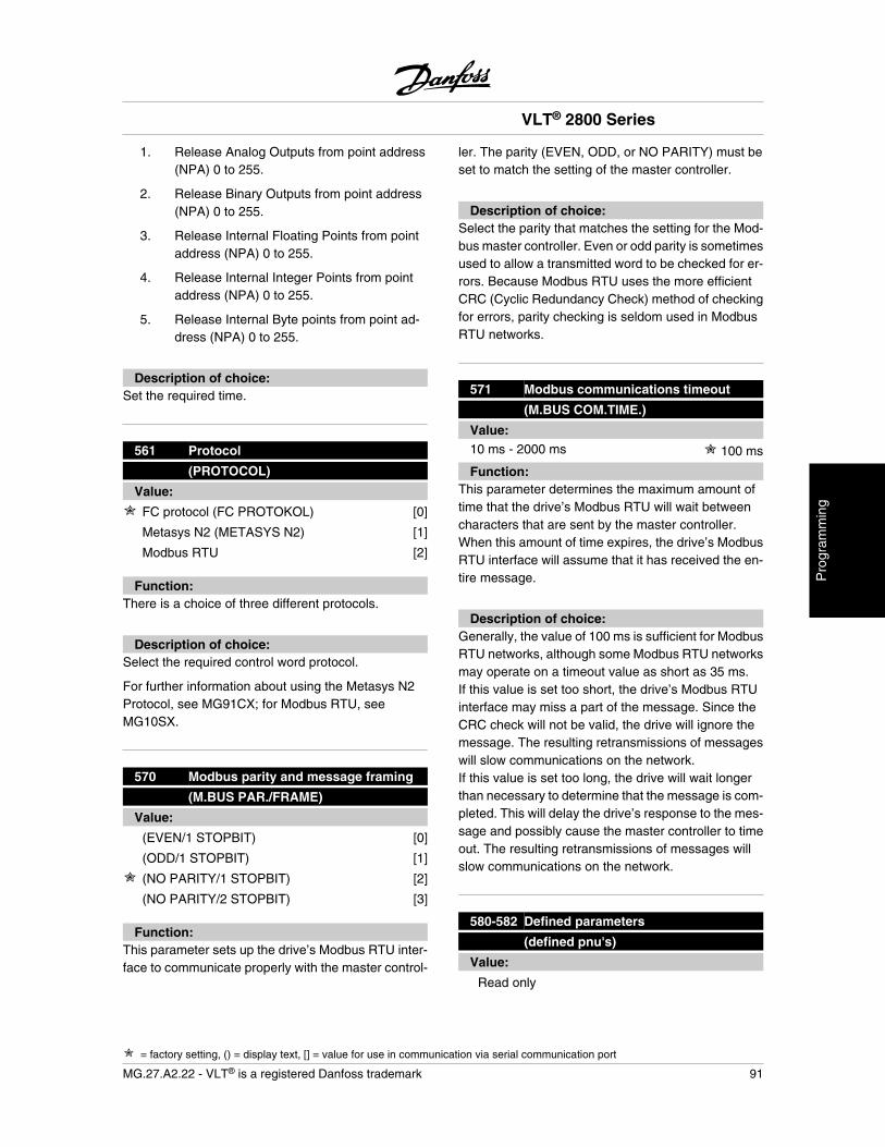
1. Release Analog Outputs from point address(NPA) 0 to 255.
2. Release Binary Outputs from point address(NPA) 0 to 255.
3. Release Internal Floating Points from pointaddress (NPA) 0 to 255.
4. Release Internal Integer Points from pointaddress (NPA) 0 to 255.
5. Release Internal Byte points from point ad-dress (NPA) 0 to 255.
Description of choice:Set the required time.
561 Protocol
(PROTOCOL)
Value:
FC protocol (FC PROTOKOL) [0]
Metasys N2 (METASYS N2) [1]
Modbus RTU [2]
Function:There is a choice of three different protocols.
Description of choice:Select the required control word protocol.
For further information about using the Metasys N2Protocol, see MG91CX; for Modbus RTU, seeMG10SX.
570 Modbus parity and message framing
(M.BUS PAR./FRAME)
Value:
(EVEN/1 STOPBIT) [0]
(ODD/1 STOPBIT) [1]
(NO PARITY/1 STOPBIT) [2]
(NO PARITY/2 STOPBIT) [3]
Function:This parameter sets up the drive’s Modbus RTU inter-face to communicate properly with the master control-
ler. The parity (EVEN, ODD, or NO PARITY) must beset to match the setting of the master controller.
Description of choice:Select the parity that matches the setting for the Mod-bus master controller. Even or odd parity is sometimesused to allow a transmitted word to be checked for er-rors. Because Modbus RTU uses the more efficientCRC (Cyclic Redundancy Check) method of checkingfor errors, parity checking is seldom used in ModbusRTU networks.
571 Modbus communications timeout
(M.BUS COM.TIME.)
Value:10 ms - 2000 ms 100 ms
Function:This parameter determines the maximum amount oftime that the drive’s Modbus RTU will wait betweencharacters that are sent by the master controller.When this amount of time expires, the drive’s ModbusRTU interface will assume that it has received the en-tire message.
Description of choice:Generally, the value of 100 ms is sufficient for ModbusRTU networks, although some Modbus RTU networksmay operate on a timeout value as short as 35 ms.If this value is set too short, the drive’s Modbus RTUinterface may miss a part of the message. Since theCRC check will not be valid, the drive will ignore themessage. The resulting retransmissions of messageswill slow communications on the network.If this value is set too long, the drive will wait longerthan necessary to determine that the message is com-pleted. This will delay the drive’s response to the mes-sage and possibly cause the master controller to timeout. The resulting retransmissions of messages willslow communications on the network.
580-582 Defined parameters
(defined pnu's)
Value:
Read only
VLT® 2800 Series
= factory setting, () = display text, [] = value for use in communication via serial communication port
MG.27.A2.22 - VLT® is a registered Danfoss trademark 91
Pro
gram
min
g
Function:The three parameters hold a list of all the parametersthat are defined in the VLT 2800. It is possible to readsingle elements of the list by using the correspondingsubindex. The subindexes start at 1 and follow the or-der of the parameter numbers.
Each parameter holds up to 116 elements (parameternumbers).
When a 0 is returned as parameter number the listends.
VLT® 2800 Series
92 MG.27.A2.22 - VLT® is a registered Danfoss trademark
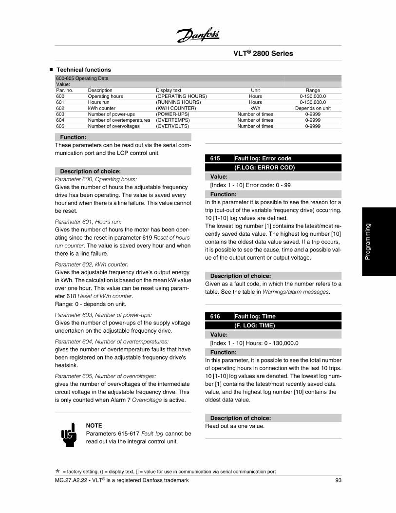
Technical functions600-605 Operating DataValue:Par. no. Description Display text Unit Range600 Operating hours (OPERATING HOURS) Hours 0-130,000.0601 Hours run (RUNNING HOURS) Hours 0-130,000.0602 kWh counter (KWH COUNTER) kWh Depends on unit603 Number of power-ups (POWER-UPS) Number of times 0-9999604 Number of overtemperatures (OVERTEMPS) Number of times 0-9999605 Number of overvoltages (OVERVOLTS) Number of times 0-9999
Function:These parameters can be read out via the serial com-munication port and the LCP control unit.
Description of choice:Parameter 600, Operating hours:Gives the number of hours the adjustable frequencydrive has been operating. The value is saved everyhour and when there is a line failure. This value cannotbe reset.
Parameter 601, Hours run:Gives the number of hours the motor has been oper-ating since the reset in parameter 619 Reset of hoursrun counter. The value is saved every hour and whenthere is a line failure.
Parameter 602, kWh counter:Gives the adjustable frequency drive's output energyin kWh. The calculation is based on the mean kW valueover one hour. This value can be reset using param-eter 618 Reset of kWh counter.Range: 0 - depends on unit.
Parameter 603, Number of power-ups:Gives the number of power-ups of the supply voltageundertaken on the adjustable frequency drive.
Parameter 604, Number of overtemperatures:gives the number of overtemperature faults that havebeen registered on the adjustable frequency drive'sheatsink.
Parameter 605, Number of overvoltages:gives the number of overvoltages of the intermediatecircuit voltage in the adjustable frequency drive. Thisis only counted when Alarm 7 Overvoltage is active.
NOTEParameters 615-617 Fault log cannot beread out via the integral control unit.
615 Fault log: Error code
(F.LOG: ERROR COD)
Value:[Index 1 - 10] Error code: 0 - 99
Function:In this parameter it is possible to see the reason for atrip (cut-out of the variable frequency drive) occurring.10 [1-10] log values are defined.The lowest log number [1] contains the latest/most re-cently saved data value. The highest log number [10]contains the oldest data value saved. If a trip occurs,it is possible to see the cause, time and a possible val-ue of the output current or output voltage.
Description of choice:Given as a fault code, in which the number refers to atable. See the table in Warnings/alarm messages.
616 Fault log: Time
(F. LOG: TIME)
Value:[Index 1 - 10] Hours: 0 - 130,000.0
Function:In this parameter, it is possible to see the total numberof operating hours in connection with the last 10 trips.10 [1-10] log values are denoted. The lowest log num-ber [1] contains the latest/most recently saved datavalue, and the highest log number [10] contains theoldest data value.
Description of choice:Read out as one value.
VLT® 2800 Series
= factory setting, () = display text, [] = value for use in communication via serial communication port
MG.27.A2.22 - VLT® is a registered Danfoss trademark 93
Pro
gram
min
g

617 Fault log: Value
(F.LOG: VALUE)
Value:[Index 1 - 10] Value: 0 - 9999
Function:In this parameter it is possible to see at which value atrip occurred. The unit of the value depends on whichalarm is active in parameter 615 Fault log: Faultcode .
Description of choice:Read out as one value.
618 Reset of kWh counter
(RESET KWH COUNT)
Value:
No reset (DO NOT RESET) [0]
Reset (RESET COUNTER) [1]
Function:Resetting parameter 602 kWh counter to zero.
Description of choice:If Reset [1]is selected and you press the [OK] key, thevariable frequency drive's kWh counter is reset to zero.This parameter cannot be selected via serial commu-nication.
NOTEWhen the [OK] key is activated, the coun-ter is reset to zero.
619 RESET RUNNING HOURS COUNTER
(RESET RUN. HOUR)
Value:
No reset (DO NOT RESET) [0]
Reset (RESET COUNTER) [1]
Function:Resetting of parameter 601 Hours run to zero.
Description of choice:If Reset [1] is selected and you press the [OK] key, thevariable frequency drive's parameter 601 is reset tozero Hours run. This parameter cannot be selected viaserial communication.
NOTEWhen the [OK] key is activated the pa-rameter is reset to zero.
620 Operation Mode
(OPERATION MODE)
Value:
Normal operation (NORMAL OPERATION) [0]
Control card test (CONTROL CARD TEST) [2]
Initialize (INITIALIZE) [3]
Function:In addition to its normal function, this parameter canbe used to test the control card.There is also the opportunity to perform an initializationat the factory setting for all parameters in all Setups,with the exception of parameters 500 Address, 501Baudrate, 600-605 Operating data and 615-617 Faultlog.
Description of choice:Normal function [0] is used for normal operation of themotor.
Control card test [2] is selected if you wish to check thecontrol card's analog/digital inputs, analog/digital out-puts, relay outputs and 10 V and 24 V voltages.The test is performed as follows:27 - 29 - 33 - 46 are connected.50 - 53 are connected.42 - 60 are connected.12 - relay terminal 01 is connected.18 - relay terminal 02 is connected.19 - relay terminal 03 is connected.
See also the DeviceNet manual MG.90.BX.YY for fur-ther details.
VLT® 2800 Series
= factory setting, () = display text, [] = value for use in communication via serial communication port
94 MG.27.A2.22 - VLT® is a registered Danfoss trademark
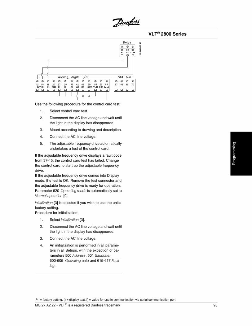
Use the following procedure for the control card test:
1. Select control card test.
2. Disconnect the AC line voltage and wait untilthe light in the display has disappeared.
3. Mount according to drawing and description.
4. Connect the AC line voltage.
5. The adjustable frequency drive automaticallyundertakes a test of the control card.
If the adjustable frequency drive displays a fault codefrom 37-45, the control card test has failed. Changethe control card to start up the adjustable frequencydrive.If the adjustable frequency drive comes into Displaymode, the test is OK. Remove the test connector andthe adjustable frequency drive is ready for operation.Parameter 620 Operating mode is automatically set toNormal operation [0].
Initialization [3] is selected if you wish to use the unit'sfactory setting.Procedure for initialization:
1. Select Initialization [3].
2. Disconnect the AC line voltage and wait untilthe light in the display has disappeared.
3. Connect the AC line voltage.
4. An initialization is performed in all parame-ters in all Setups, with the exception of pa-rameters 500 Address, 501 Baudrate,600-605 Operating data and 615-617 Faultlog.
VLT® 2800 Series
= factory setting, () = display text, [] = value for use in communication via serial communication port
MG.27.A2.22 - VLT® is a registered Danfoss trademark 95
Pro
gram
min
g
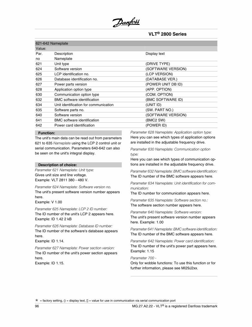
621-642 NameplateValue:Par.no
DescriptionNameplate
Display text
621 Unit type (DRIVE TYPE)624 Software version (SOFTWARE VERSION)625 LCP identification no. (LCP VERSION)626 Database identification no. (DATABASE VER.)627 Power parts version (POWER UNIT DB ID)628 Application option type (APP. OPTION)630 Communication option type (COM. OPTION)632 BMC software identification (BMC SOFTWARE ID)634 Unit identification for communication (UNIT ID)635 Software parts no. (SW. PART NO.)640 Software version (SOFTWARE VERSION)641 BMC software identification (BMC2 SW)642 Power card identification (POWER ID)
Function:The unit's main data can be read out from parameters621 to 635 Nameplate using the LCP 2 control unit orserial communication. Parameters 640-642 can alsobe seen on the unit's integral display.
Description of choice:Parameter 621 Nameplate: Unit type:Gives unit size and line voltage.Example: VLT 2811 380 - 480 V.
Parameter 624 Nameplate: Software version no.The unit's present software version number appearshere.Example: V 1.00
Parameter 625 Nameplate: LCP 2 ID number:The ID number of the unit's LCP 2 appears here.Example: ID 1.42 2 kB
Parameter 626 Nameplate: Database ID number:The ID number of the software's database appearshere.Example: ID 1.14.
Parameter 627 Nameplate: Power section version:The ID number of the unit's power section appearshere.Example: ID 1.15.
Parameter 628 Nameplate: Application option type:Here you can see which types of application optionsare installed in the adjustable frequency drive.
Parameter 630 Nameplate: Communication optiontype:Here you can see which types of communication op-tions are installed in the adjustable frequency drive.
Parameter 632 Nameplate: BMC software identification:The ID number of the BMC software appears here.
Parameter 634 Nameplate: Unit identification for com-munication:The ID number for communication appears here.
Parameter 635 Nameplate: Software section no.:The software section number appears here.
Parameter 640 Nameplate: Software version:The unit's present software version number appearshere. Example: 1.00
Parameter 641 Nameplate: BMC software identification:The ID number of the BMC software appears here.
Parameter 642 Nameplate: Power card identification:The ID number of the unit's power part appears here.Example: 1.15
Parameter 700 -Only for wobble functions: To use this function or forfurther information, please see MI29J2xx.
VLT® 2800 Series
= factory setting, () = display text, [] = value for use in communication via serial communication port
96 MG.27.A2.22 - VLT® is a registered Danfoss trademark
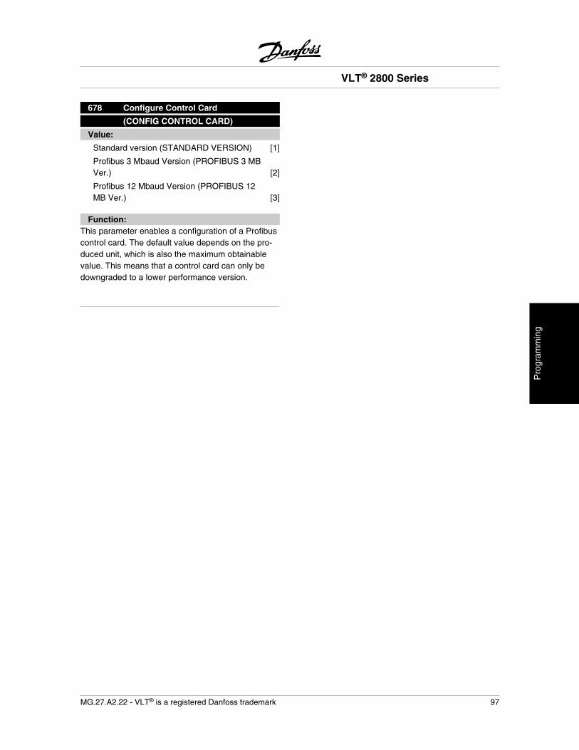
678 Configure Control Card
(CONFIG CONTROL CARD)
Value:
Standard version (STANDARD VERSION) [1]
Profibus 3 Mbaud Version (PROFIBUS 3 MBVer.) [2]
Profibus 12 Mbaud Version (PROFIBUS 12MB Ver.) [3]
Function:This parameter enables a configuration of a Profibuscontrol card. The default value depends on the pro-duced unit, which is also the maximum obtainablevalue. This means that a control card can only bedowngraded to a lower performance version.
VLT® 2800 Series
MG.27.A2.22 - VLT® is a registered Danfoss trademark 97
Pro
gram
min
g
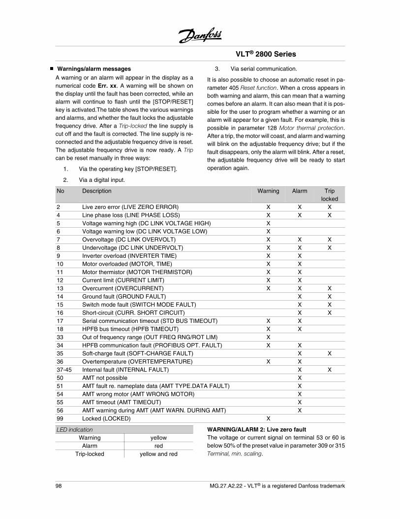
Warnings/alarm messages
A warning or an alarm will appear in the display as anumerical code Err. xx. A warning will be shown onthe display until the fault has been corrected, while analarm will continue to flash until the [STOP/RESET]key is activated.The table shows the various warningsand alarms, and whether the fault locks the adjustablefrequency drive. After a Trip-locked the line supply iscut off and the fault is corrected. The line supply is re-connected and the adjustable frequency drive is reset.The adjustable frequency drive is now ready. A Tripcan be reset manually in three ways:
1. Via the operating key [STOP/RESET].
2. Via a digital input.
3. Via serial communication.
It is also possible to choose an automatic reset in pa-rameter 405 Reset function. When a cross appears inboth warning and alarm, this can mean that a warningcomes before an alarm. It can also mean that it is pos-sible for the user to program whether a warning or analarm will appear for a given fault. For example, this ispossible in parameter 128 Motor thermal protection.After a trip, the motor will coast, and alarm and warningwill blink on the adjustable frequency drive; but if thefault disappears, only the alarm will blink. After a reset,the adjustable frequency drive will be ready to startoperation again.
No Description Warning Alarm Triplocked
2 Live zero error (LIVE ZERO ERROR) X X X4 Line phase loss (LINE PHASE LOSS) X X X5 Voltage warning high (DC LINK VOLTAGE HIGH) X6 Voltage warning low (DC LINK VOLTAGE LOW) X7 Overvoltage (DC LINK OVERVOLT) X X X8 Undervoltage (DC LINK UNDERVOLT) X X X9 Inverter overload (INVERTER TIME) X X10 Motor overloaded (MOTOR, TIME) X X11 Motor thermistor (MOTOR THERMISTOR) X X12 Current limit (CURRENT LIMIT) X X13 Overcurrent (OVERCURRENT) X X X14 Ground fault (GROUND FAULT) X X15 Switch mode fault (SWITCH MODE FAULT) X X16 Short-circuit (CURR. SHORT CIRCUIT) X X17 Serial communication timeout (STD BUS TIMEOUT) X X18 HPFB bus timeout (HPFB TIMEOUT) X X33 Out of frequency range (OUT FREQ RNG/ROT LIM) X34 HPFB communication fault (PROFIBUS OPT. FAULT) X X35 Soft-charge fault (SOFT-CHARGE FAULT) X X36 Overtemperature (OVERTEMPERATURE) X X37-45 Internal fault (INTERNAL FAULT) X X50 AMT not possible X51 AMT fault re. nameplate data (AMT TYPE.DATA FAULT) X54 AMT wrong motor (AMT WRONG MOTOR) X55 AMT timeout (AMT TIMEOUT) X56 AMT warning during AMT (AMT WARN. DURING AMT) X99 Locked (LOCKED) X
LED indicationWarning yellow
Alarm redTrip-locked yellow and red
WARNING/ALARM 2: Live zero faultThe voltage or current signal on terminal 53 or 60 isbelow 50% of the preset value in parameter 309 or 315Terminal, min. scaling.
VLT® 2800 Series
98 MG.27.A2.22 - VLT® is a registered Danfoss trademark
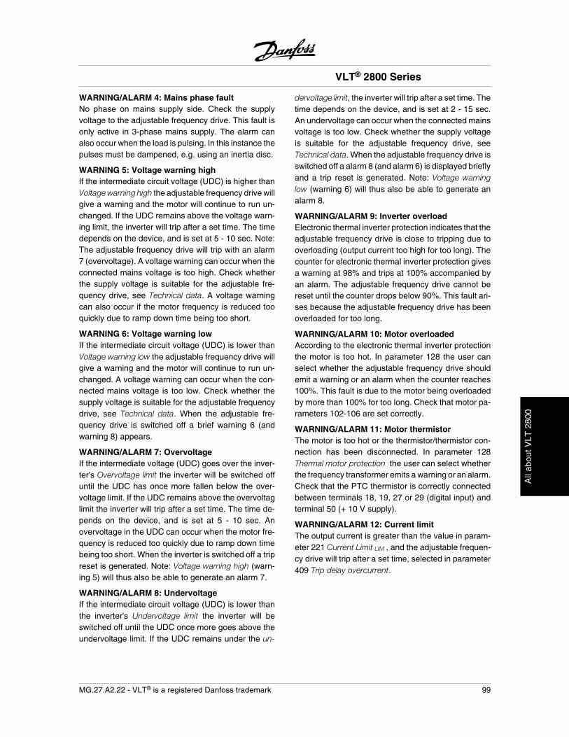
WARNING/ALARM 4: Mains phase faultNo phase on mains supply side. Check the supplyvoltage to the adjustable frequency drive. This fault isonly active in 3-phase mains supply. The alarm canalso occur when the load is pulsing. In this instance thepulses must be dampened, e.g. using an inertia disc.
WARNING 5: Voltage warning highIf the intermediate circuit voltage (UDC) is higher thanVoltage warning high the adjustable frequency drive willgive a warning and the motor will continue to run un-changed. If the UDC remains above the voltage warn-ing limit, the inverter will trip after a set time. The timedepends on the device, and is set at 5 - 10 sec. Note:The adjustable frequency drive will trip with an alarm7 (overvoltage). A voltage warning can occur when theconnected mains voltage is too high. Check whetherthe supply voltage is suitable for the adjustable fre-quency drive, see Technical data. A voltage warningcan also occur if the motor frequency is reduced tooquickly due to ramp down time being too short.
WARNING 6: Voltage warning lowIf the intermediate circuit voltage (UDC) is lower thanVoltage warning low the adjustable frequency drive willgive a warning and the motor will continue to run un-changed. A voltage warning can occur when the con-nected mains voltage is too low. Check whether thesupply voltage is suitable for the adjustable frequencydrive, see Technical data. When the adjustable fre-quency drive is switched off a brief warning 6 (andwarning 8) appears.
WARNING/ALARM 7: OvervoltageIf the intermediate voltage (UDC) goes over the inver-ter's Overvoltage limit the inverter will be switched offuntil the UDC has once more fallen below the over-voltage limit. If the UDC remains above the overvoltaglimit the inverter will trip after a set time. The time de-pends on the device, and is set at 5 - 10 sec. Anovervoltage in the UDC can occur when the motor fre-quency is reduced too quickly due to ramp down timebeing too short. When the inverter is switched off a tripreset is generated. Note: Voltage warning high (warn-ing 5) will thus also be able to generate an alarm 7.
WARNING/ALARM 8: UndervoltageIf the intermediate circuit voltage (UDC) is lower thanthe inverter's Undervoltage limit the inverter will beswitched off until the UDC once more goes above theundervoltage limit. If the UDC remains under the un-
dervoltage limit, the inverter will trip after a set time. Thetime depends on the device, and is set at 2 - 15 sec.An undervoltage can occur when the connected mainsvoltage is too low. Check whether the supply voltageis suitable for the adjustable frequency drive, seeTechnical data. When the adjustable frequency drive isswitched off a alarm 8 (and alarm 6) is displayed brieflyand a trip reset is generated. Note: Voltage warninglow (warning 6) will thus also be able to generate analarm 8.
WARNING/ALARM 9: Inverter overloadElectronic thermal inverter protection indicates that theadjustable frequency drive is close to tripping due tooverloading (output current too high for too long). Thecounter for electronic thermal inverter protection givesa warning at 98% and trips at 100% accompanied byan alarm. The adjustable frequency drive cannot bereset until the counter drops below 90%. This fault ari-ses because the adjustable frequency drive has beenoverloaded for too long.
WARNING/ALARM 10: Motor overloadedAccording to the electronic thermal inverter protectionthe motor is too hot. In parameter 128 the user canselect whether the adjustable frequency drive shouldemit a warning or an alarm when the counter reaches100%. This fault is due to the motor being overloadedby more than 100% for too long. Check that motor pa-rameters 102-106 are set correctly.
WARNING/ALARM 11: Motor thermistorThe motor is too hot or the thermistor/thermistor con-nection has been disconnected. In parameter 128Thermal motor protection the user can select whetherthe frequency transformer emits a warning or an alarm.Check that the PTC thermistor is correctly connectedbetween terminals 18, 19, 27 or 29 (digital input) andterminal 50 (+ 10 V supply).
WARNING/ALARM 12: Current limitThe output current is greater than the value in param-eter 221 Current Limit LIM , and the adjustable frequen-cy drive will trip after a set time, selected in parameter409 Trip delay overcurrent.
VLT® 2800 Series
MG.27.A2.22 - VLT® is a registered Danfoss trademark 99
All
abou
t VLT
280
0
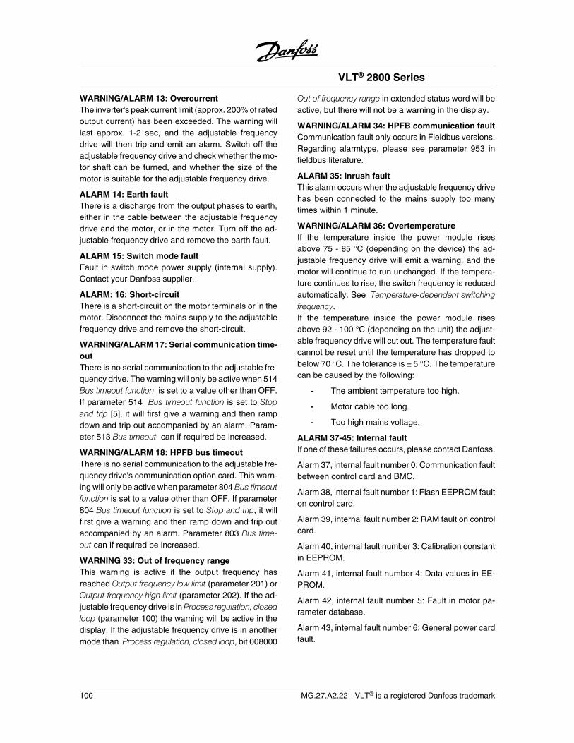
WARNING/ALARM 13: OvercurrentThe inverter's peak current limit (approx. 200% of ratedoutput current) has been exceeded. The warning willlast approx. 1-2 sec, and the adjustable frequencydrive will then trip and emit an alarm. Switch off theadjustable frequency drive and check whether the mo-tor shaft can be turned, and whether the size of themotor is suitable for the adjustable frequency drive.
ALARM 14: Earth faultThere is a discharge from the output phases to earth,either in the cable between the adjustable frequencydrive and the motor, or in the motor. Turn off the ad-justable frequency drive and remove the earth fault.
ALARM 15: Switch mode faultFault in switch mode power supply (internal supply).Contact your Danfoss supplier.
ALARM: 16: Short-circuitThere is a short-circuit on the motor terminals or in themotor. Disconnect the mains supply to the adjustablefrequency drive and remove the short-circuit.
WARNING/ALARM 17: Serial communication time-outThere is no serial communication to the adjustable fre-quency drive. The warning will only be active when 514Bus timeout function is set to a value other than OFF.If parameter 514 Bus timeout function is set to Stopand trip [5], it will first give a warning and then rampdown and trip out accompanied by an alarm. Param-eter 513 Bus timeout can if required be increased.
WARNING/ALARM 18: HPFB bus timeoutThere is no serial communication to the adjustable fre-quency drive's communication option card. This warn-ing will only be active when parameter 804 Bus timeoutfunction is set to a value other than OFF. If parameter804 Bus timeout function is set to Stop and trip, it willfirst give a warning and then ramp down and trip outaccompanied by an alarm. Parameter 803 Bus time-out can if required be increased.
WARNING 33: Out of frequency rangeThis warning is active if the output frequency hasreached Output frequency low limit (parameter 201) orOutput frequency high limit (parameter 202). If the ad-justable frequency drive is in Process regulation, closedloop (parameter 100) the warning will be active in thedisplay. If the adjustable frequency drive is in anothermode than Process regulation, closed loop, bit 008000
Out of frequency range in extended status word will beactive, but there will not be a warning in the display.
WARNING/ALARM 34: HPFB communication faultCommunication fault only occurs in Fieldbus versions.Regarding alarmtype, please see parameter 953 infieldbus literature.
ALARM 35: Inrush faultThis alarm occurs when the adjustable frequency drivehas been connected to the mains supply too manytimes within 1 minute.
WARNING/ALARM 36: OvertemperatureIf the temperature inside the power module risesabove 75 - 85 °C (depending on the device) the ad-justable frequency drive will emit a warning, and themotor will continue to run unchanged. If the tempera-ture continues to rise, the switch frequency is reducedautomatically. See Temperature-dependent switchingfrequency.If the temperature inside the power module risesabove 92 - 100 °C (depending on the unit) the adjust-able frequency drive will cut out. The temperature faultcannot be reset until the temperature has dropped tobelow 70 °C. The tolerance is ± 5 °C. The temperaturecan be caused by the following:
- The ambient temperature too high.
- Motor cable too long.
- Too high mains voltage.
ALARM 37-45: Internal faultIf one of these failures occurs, please contact Danfoss.
Alarm 37, internal fault number 0: Communication faultbetween control card and BMC.
Alarm 38, internal fault number 1: Flash EEPROM faulton control card.
Alarm 39, internal fault number 2: RAM fault on controlcard.
Alarm 40, internal fault number 3: Calibration constantin EEPROM.
Alarm 41, internal fault number 4: Data values in EE-PROM.
Alarm 42, internal fault number 5: Fault in motor pa-rameter database.
Alarm 43, internal fault number 6: General power cardfault.
VLT® 2800 Series
100 MG.27.A2.22 - VLT® is a registered Danfoss trademark
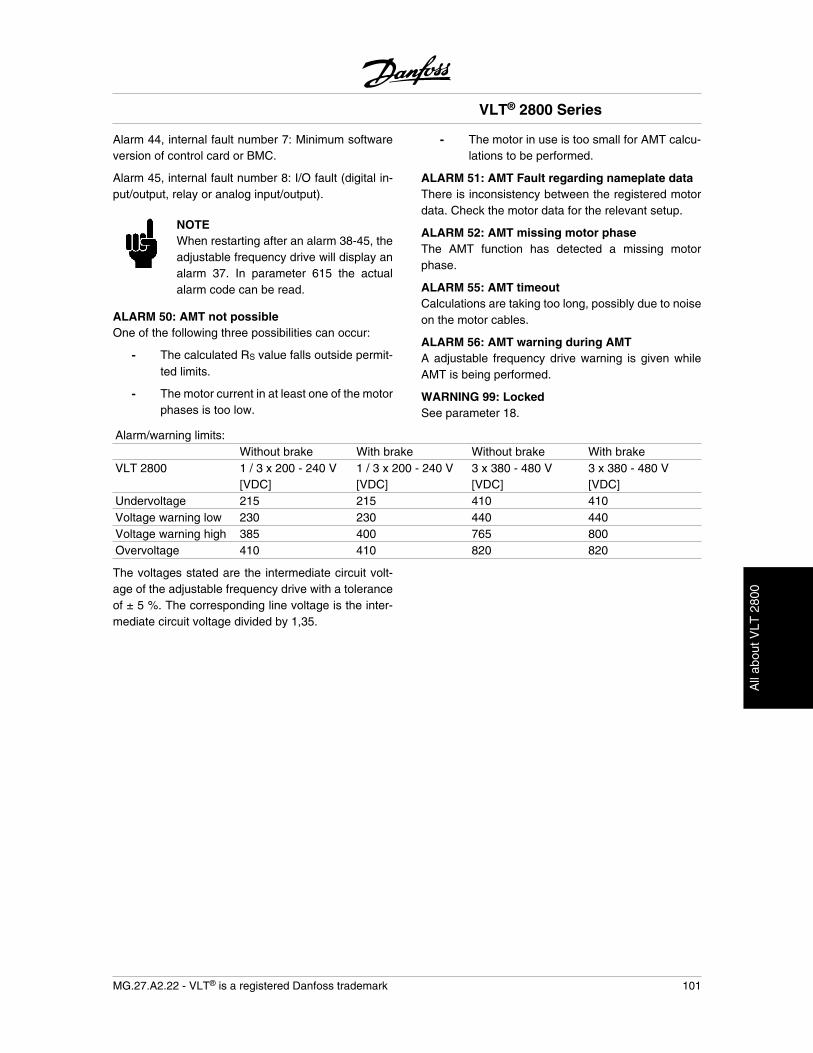
Alarm 44, internal fault number 7: Minimum softwareversion of control card or BMC.
Alarm 45, internal fault number 8: I/O fault (digital in-put/output, relay or analog input/output).
NOTEWhen restarting after an alarm 38-45, theadjustable frequency drive will display analarm 37. In parameter 615 the actualalarm code can be read.
ALARM 50: AMT not possibleOne of the following three possibilities can occur:
- The calculated RS value falls outside permit-ted limits.
- The motor current in at least one of the motorphases is too low.
- The motor in use is too small for AMT calcu-lations to be performed.
ALARM 51: AMT Fault regarding nameplate dataThere is inconsistency between the registered motordata. Check the motor data for the relevant setup.
ALARM 52: AMT missing motor phaseThe AMT function has detected a missing motorphase.
ALARM 55: AMT timeoutCalculations are taking too long, possibly due to noiseon the motor cables.
ALARM 56: AMT warning during AMTA adjustable frequency drive warning is given whileAMT is being performed.
WARNING 99: LockedSee parameter 18.
Alarm/warning limits: Without brake With brake Without brake With brake
VLT 2800 1 / 3 x 200 - 240 V[VDC]
1 / 3 x 200 - 240 V[VDC]
3 x 380 - 480 V[VDC]
3 x 380 - 480 V[VDC]
Undervoltage 215 215 410 410Voltage warning low 230 230 440 440Voltage warning high 385 400 765 800Overvoltage 410 410 820 820
The voltages stated are the intermediate circuit volt-age of the adjustable frequency drive with a toleranceof ± 5 %. The corresponding line voltage is the inter-mediate circuit voltage divided by 1,35.
VLT® 2800 Series
MG.27.A2.22 - VLT® is a registered Danfoss trademark 101
All
abou
t VLT
280
0
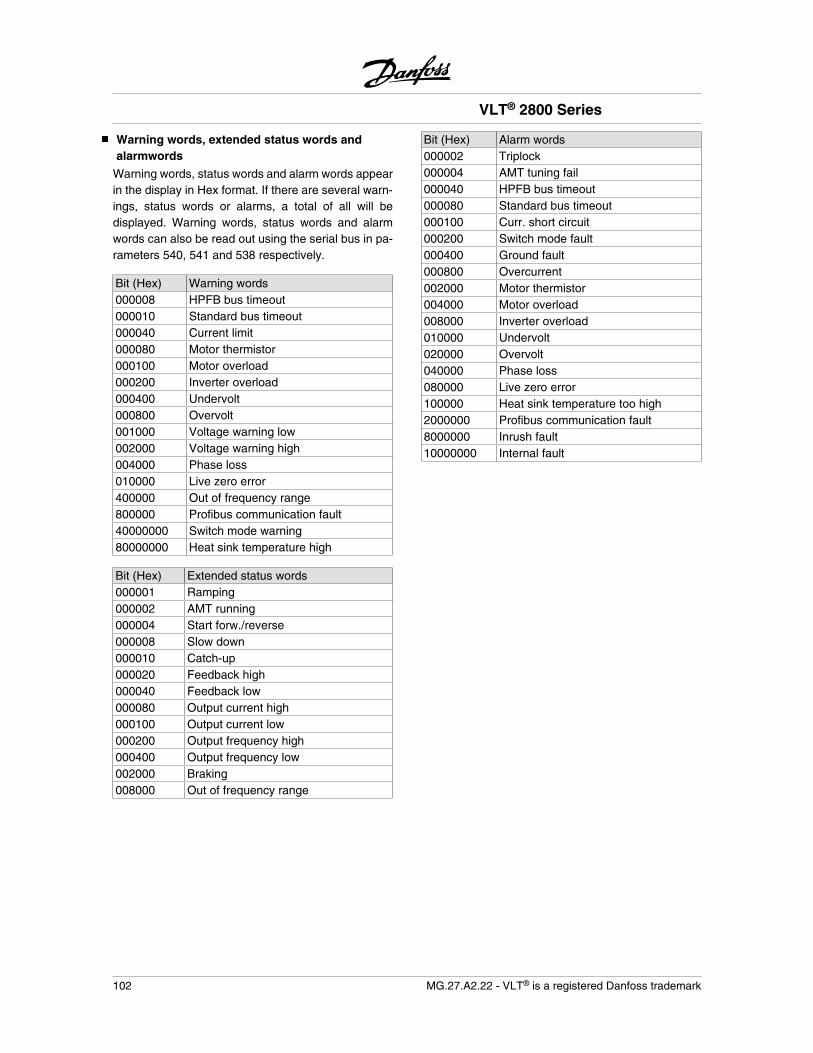
Warning words, extended status words andalarmwords
Warning words, status words and alarm words appearin the display in Hex format. If there are several warn-ings, status words or alarms, a total of all will bedisplayed. Warning words, status words and alarmwords can also be read out using the serial bus in pa-rameters 540, 541 and 538 respectively.
Bit (Hex) Warning words000008 HPFB bus timeout000010 Standard bus timeout000040 Current limit000080 Motor thermistor000100 Motor overload000200 Inverter overload000400 Undervolt000800 Overvolt001000 Voltage warning low002000 Voltage warning high004000 Phase loss010000 Live zero error400000 Out of frequency range800000 Profibus communication fault40000000 Switch mode warning80000000 Heat sink temperature high
Bit (Hex) Extended status words000001 Ramping000002 AMT running000004 Start forw./reverse000008 Slow down000010 Catch-up000020 Feedback high000040 Feedback low000080 Output current high000100 Output current low000200 Output frequency high000400 Output frequency low002000 Braking008000 Out of frequency range
Bit (Hex) Alarm words000002 Triplock000004 AMT tuning fail000040 HPFB bus timeout000080 Standard bus timeout000100 Curr. short circuit000200 Switch mode fault000400 Ground fault000800 Overcurrent002000 Motor thermistor004000 Motor overload008000 Inverter overload010000 Undervolt020000 Overvolt040000 Phase loss080000 Live zero error100000 Heat sink temperature too high2000000 Profibus communication fault8000000 Inrush fault10000000 Internal fault
VLT® 2800 Series
102 MG.27.A2.22 - VLT® is a registered Danfoss trademark
Special conditions
Extreme environments
An adjustable frequency drive contains a number ofmechanical and electronic components which are vul-nerable to environmental impact.
Do not install the adjustable frequencydrive in environments where liquids, par-ticles or gases in the air would damage theelectronics of the drive. Take all necessa-ry measures to protect the drive. There isa risk of fault trips and reduced service lifeof the drive.
Liquids carried through the air can condense in theadjustable frequency drive. Liquids may facilitate gal-vanic corrosion of components and metal parts.Steam, oil and brine may also cause corrosion of com-ponents and metal parts. In these areas, it is recom-mended to install units in cabinets. As a minimum,cabinets should meet NEMA 12.
Particles in the air, such as dust, may lead to mechan-ical, electrical and thermal faults in the adjustable fre-quency drive. A typical indicator of too many particlesin the air is dust around the fan. In very dusty areas,mounting the drive in a cabinet is recommended. As aminimum, cabinets should meet NEMA 12.
Aggressive gases, such as sulfur, nitrogen and chlor-ine compounds, together with high humidity and tem-perature, facilitate possible chemical processes on thecomponents of the adjustable frequency drive. Thesechemical processes quickly damage the electronics. Inthese areas, mounting in a cabinet with fresh-air cir-culation is recommended, thereby ensuring that ag-gressive gases are kept away from the drive.
NOTEInstallation of adjustable frequency drivesin extreme environments increases therisk of down-time, and considerable re-duction of the service life of the drive.
Before the adjustable frequency drive is installed,check whether there are liquids, particles or gases inthe air. Examine existing installations in the same en-vironment. Typical indicators of harmful airborne liq-uids are water or oil on metal parts or corrosion. Toomany dust particles are typically observed on top ofcabinets. Indication of aggressive gases in the air are
black copper rails and cable ends on existing electricalinstallations.
Galvanic Isolation (PELV)
PELV (Protective Extra Low Voltage) insulation is ach-ieved by inserting galvanic isolators between the con-trol circuits and circuits that are connected to the linepower potential. The VLT is designed to meet the re-quirements for protective separation by means of hav-ing the necessary creepage and clearance distances.These requirements are described in standard EN 50178. It is also a requirement that the installation is car-ried out in accordance with local/national regulationsregarding PELV.
All control terminals, terminals for serial communica-tion and relay terminals are safely separated from theline power potential, which is to say that they complywith the PELV requirements. Circuits that are connec-ted to control terminals 12, 18, 19, 20, 27, 29, 33, 42,46, 50, 53, 55 and 60 are galvanically connected toone another. Serial communication connected to serialcommunication bus is galvanically insulated from thecontrol terminals, although this is only a functional in-sulation.The relay contacts on terminals 1-3 are insulated fromthe other control circuits with reinforced/double isola-tion, i.e., PELV is observed for these, even thoughthere is line power potential at the relay terminals.
The circuit elements described below form the safeelectric separation. They fulfill the requirements for re-inforced/double insulation and associated testing pur-suant to EN 50 178.
1. Transformer and optical separation in voltagesupply.
2. Optical insulation between the basic motorcontrol and the control card.
3. Insulation between the control card and thepower part.
4. Relay contacts and terminals relating to othercircuits on the control card.
PELV insulation of the control card is guaranteed un-der the following conditions:
- TT network with maximum 300 Vrms be-tween phase and ground.
VLT® 2800 Series
MG.27.A2.22 - VLT® is a registered Danfoss trademark 103
All
abou
t VLT
280
0
- TN network with maximum 300 Vrms be-tween phase and ground.
- IT network with maximum 400 Vrms betweenphase and ground.
In order to maintain PELV, all connections made to thecontrol terminals must be PELV. For example, thethermistor must be reinforced/double insulated.
UL Standard
This device is UL-approved.
VLT® 2800 Series
104 MG.27.A2.22 - VLT® is a registered Danfoss trademark
General technical data
Line power supply (L1, L2, L3):Supply voltage VLT 2803-2840 220-240 V (N, L1) 1 x 220/230/240 V ±10%Supply voltage VLT 2803-2840 200-240 V 3 x 200/208/220/230/240 V ±10%Supply voltage VLT 2805-2882 380-480 V 3 x 380/400/415/440/480 V ±10%Supply voltage VLT 2805-2840 (R5) 380/400 V + 10%Supply frequency 50/60 Hz ± 3 HzMax. imbalance on supply voltage ± 2.0% of rated supply voltageTrue Power Factor ( ) 0.90 nominal at rated loadDisplacement Power Factor (cos ) near unity (> 0.98)Number of connections at supply input L1, L2, L3 2 times/min.Max. short circuit value 100,000 A
See Special Conditions section in the Design Guide
Output data (U, V, W):Output voltage 0 - 100% of supply voltageOutput frequency 0.2 - 132 Hz, 1 - 1000 HzRated motor voltage, 200-240 V units 200/208/220/230/240 VRated motor voltage, 380-480 V units 380/400/415/440/460/480 VRated motor frequency 50/60 HzSwitching on output UnlimitedRamp times 0.02 - 3600 sec.
Torque characteristics:
Starting torque (parameter 101 Torque characteristic = Constant torque) 160% in 1 min.*
Starting torque (parameter 101 Torque characteristics = Variable torque) 160% in 1 min.*
Starting torque (parameter 119 High starting torque ) 180% for 0.5 sec.Overload torque (parameter 101 Torque characteristic = Constant torque) 160%*Overload torque (parameter 101 Torque characteristic = Variable torque) 160%*
Percentage relates to adjustable frequency drive's nominal current.* VLT 2822 PD2 / 2840 PD2 1 x 220 V only 110% in 1 min.
Control card, digital inputs:Number of programmable digital inputs 5Terminal number 18, 19, 27, 29, 33Voltage level 0-24 V DC (PNP positive logic)Voltage level, logic '0' < 5 V DCVoltage level, logic '1' > 10 V DCMaximum voltage on input 28 V DCInput resistance, Ri (terminals 18, 19, 27, 29) approximately 4 kInput resistance, Ri (terminal 33) approximately 2 k
All digital inputs are galvanically isolated from the supply voltage (PELV) and other high-voltage terminals. See sectionentitled Galvanic Isolation.
VLT® 2800 Series
MG.27.A2.22 - VLT® is a registered Danfoss trademark 105
All
abou
t VLT
280
0
Control card, analog inputs:Number of analog voltage inputs 1 pcs.Terminal number 53Voltage level 0 - 10 V DC (scalable)Input resistance, Ri approx. 10 kMax. voltage 20 VNumber of analog current inputs 1 pcs.Terminal number 60Current level 0/4 - 20 mA (scalable)Input resistance, Ri approx. 300 Max. current 30 mAResolution for analog inputs 10 bitAccuracy of analog inputs Max. error 1% of full scaleScan interval 13.3 msec
The analog inputs are galvanically isolated from the supply voltage (PELV) and other high-voltage terminals. Seesection entitled Galvanic Isolation.
Control card, pulse inputs:Number of programmable pulse inputs 1Terminal number 33Max. frequency on terminal 33 67.6 kHz (Push-pull)Max. frequency on terminal 33 5 kHz (open collector)Min. frequency on terminal 33 4 HzVoltage level 0 - 24 VDC (PNP positive logic)Voltage level, logic '0' < 5 VDCVoltage level, logic '1' > 10 VDCMaximum voltage on input 28 VDCInput resistance, Ri approx. 2 kScan interval 13.3 msecResolution 10 bitAccuracy (100 Hz - 1 kHz) terminal 33 Max. error: 0.5% of full scaleAccuracy (1 kHz - 67.6 kHz) terminal 33 Max. error: 0.1% of full scale
The pulse input (terminal 33) is galvanically isolated from the supply voltage (PELV) and other high-voltage terminals.See section entitled Galvanic Isolation.
Control card, digital/frequency outputs:Number of programmable digital/pulse outputs 1Terminal number 46Voltage level at digital/frequency output 0-24 V DC (O.C PNP)Max. output current at digital/frequency output 25 mA.Max. load at digital/frequency output 1 kMax. capacity at frequency output 10 nFMinimum output frequency at frequency output 16 HzMaximum output frequency at frequency output 10 kHzAccuracy on frequency output Max. error: 0.2% of full scaleResolution on frequency output 10 bit
The digital output is galvanically isolated from the supply voltage (PELV) and other high-voltage terminals. See sectionentitled Galvanic Isolation.
VLT® 2800 Series
106 MG.27.A2.22 - VLT® is a registered Danfoss trademark
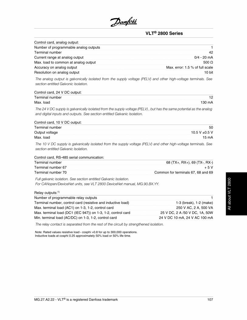
Control card, analog output:Number of programmable analog outputs 1Terminal number 42Current range at analog output 0/4 - 20 mAMax. load to common at analog output 500Accuracy on analog output Max. error: 1.5 % of full scaleResolution on analog output 10 bit
The analog output is galvonically isolated from the supply voltage (PELV) and other high-voltage terminals. Seesection entitled Galvonic Isolation.
Control card, 24 V DC output:Terminal number 12Max. load 130 mA
The 24 V DC supply is galvanically isolated from the supply voltage (PELV) , but has the same potential as the analogand digital inputs and outputs. See section entitled Galvanic Isolation.
Control card, 10 V DC output:Terminal number 50Output voltage 10.5 V ±0.5 VMax. load 15 mA
The 10 V DC supply is galvanically isolated from the supply voltage (PELV) and other high-voltage terminals. Seesection entitled Galvanic Isolation.
Control card, RS-485 serial communication:Terminal number 68 (TX+, RX+), 69 (TX-, RX-)Terminal number 67 + 5 VTerminal number 70 Common for terminals 67, 68 and 69
Full galvanic isolation. See section entitled Galvanic Isolation.For CANopen/DeviceNet units, see VLT 2800 DeviceNet manual, MG.90.BX.YY.
Relay outputs:1)
Number of programmable relay outputs 1Terminal number, control card (resistive and inductive load) 1-3 (break), 1-2 (make)Max. terminal load (AC1) on 1-3, 1-2, control card 250 V AC, 2 A, 500 VAMax. terminal load (DC1 (IEC 947)) on 1-3, 1-2, control card 25 V DC, 2 A /50 V DC, 1A, 50WMin. terminal load (AC/DC) on 1-3, 1-2, control card 24 V DC 10 mA, 24 V AC 100 mA
The relay contact is separated from the rest of the circuit by strengthened isolation.
Note: Rated values resistive load - cosphi >0.8 for up to 300,000 operations.Inductive loads at cosphi 0.25 approximately 50% load or 50% life time.
VLT® 2800 Series
MG.27.A2.22 - VLT® is a registered Danfoss trademark 107
All
abou
t VLT
280
0
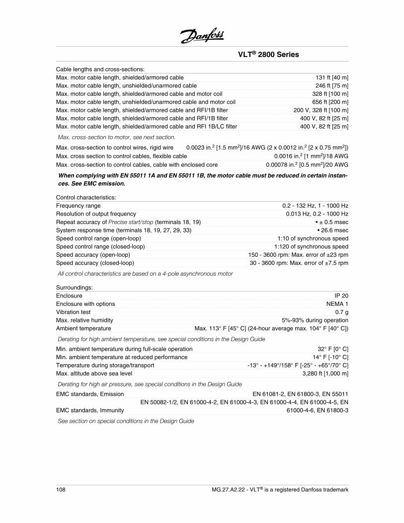
Cable lengths and cross-sections:Max. motor cable length, shielded/armored cable 131 ft [40 m]Max. motor cable length, unshielded/unarmored cable 246 ft [75 m]Max. motor cable length, shielded/armored cable and motor coil 328 ft [100 m]Max. motor cable length, unshielded/unarmored cable and motor coil 656 ft [200 m]Max. motor cable length, shielded/armored cable and RFI/1B filter 200 V, 328 ft [100 m]Max. motor cable length, shielded/armored cable and RFI/1B filter 400 V, 82 ft [25 m]Max. motor cable length, shielded/armored cable and RFI 1B/LC filter 400 V, 82 ft [25 m]
Max. cross-section to motor, see next section.
Max. cross-section to control wires, rigid wire 0.0023 in.2 [1.5 mm2]/16 AWG (2 x 0.0012 in.2 [2 x 0.75 mm2])
Max. cross section to control cables, flexible cable 0.0016 in.2 [1 mm2]/18 AWG
Max. cross-section to control cables, cable with enclosed core 0.00078 in.2 [0.5 mm2]/20 AWG
When complying with EN 55011 1A and EN 55011 1B, the motor cable must be reduced in certain instan-ces. See EMC emission.
Control characteristics:Frequency range 0.2 - 132 Hz, 1 - 1000 HzResolution of output frequency 0.013 Hz, 0.2 - 1000 HzRepeat accuracy of Precise start/stop (terminals 18, 19) • ± 0.5 msecSystem response time (terminals 18, 19, 27, 29, 33) • 26.6 msecSpeed control range (open-loop) 1:10 of synchronous speedSpeed control range (closed-loop) 1:120 of synchronous speedSpeed accuracy (open-loop) 150 - 3600 rpm: Max. error of ±23 rpmSpeed accuracy (closed-loop) 30 - 3600 rpm: Max. error of ±7.5 rpm
All control characteristics are based on a 4-pole asynchronous motor
Surroundings:Enclosure IP 20Enclosure with options NEMA 1Vibration test 0.7 gMax. relative humidity 5%-93% during operationAmbient temperature Max. 113° F [45° C] (24-hour average max. 104° F [40° C])
Derating for high ambient temperature, see special conditions in the Design Guide
Min. ambient temperature during full-scale operation 32° F [0° C]Min. ambient temperature at reduced performance 14° F [-10° C]Temperature during storage/transport -13° - +149°/158° F [-25° - +65°/70° C]Max. altitude above sea level 3,280 ft [1,000 m]
Derating for high air pressure, see special conditions in the Design Guide
EMC standards, Emission EN 61081-2, EN 61800-3, EN 55011
EMC standards, ImmunityEN 50082-1/2, EN 61000-4-2, EN 61000-4-3, EN 61000-4-4, EN 61000-4-5, EN
61000-4-6, EN 61800-3
See section on special conditions in the Design Guide
VLT® 2800 Series
108 MG.27.A2.22 - VLT® is a registered Danfoss trademark
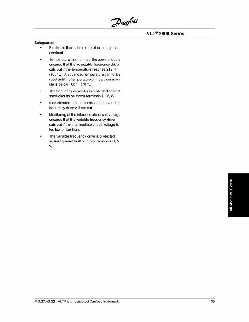
Safeguards:• Electronic thermal motor protection against
overload.
• Temperature monitoring of the power moduleensures that the adjustable frequency drivecuts out if the temperature reaches 212 °F(100 °C). An overload temperature cannot bereset until the temperature of the power mod-ule is below 160 °F (70 °C).
• The frequency converter is protected againstshort-circuits on motor terminals U, V, W.
• If an electrical phase is missing, the variablefrequency drive will cut out.
• Monitoring of the intermediate circuit voltageensures that the variable frequency drivecuts out if the intermediate circuit voltage istoo low or too high.
• The variable frequency drive is protectedagainst ground fault on motor terminals U, V,W.
VLT® 2800 Series
MG.27.A2.22 - VLT® is a registered Danfoss trademark 109
All
abou
t VLT
280
0
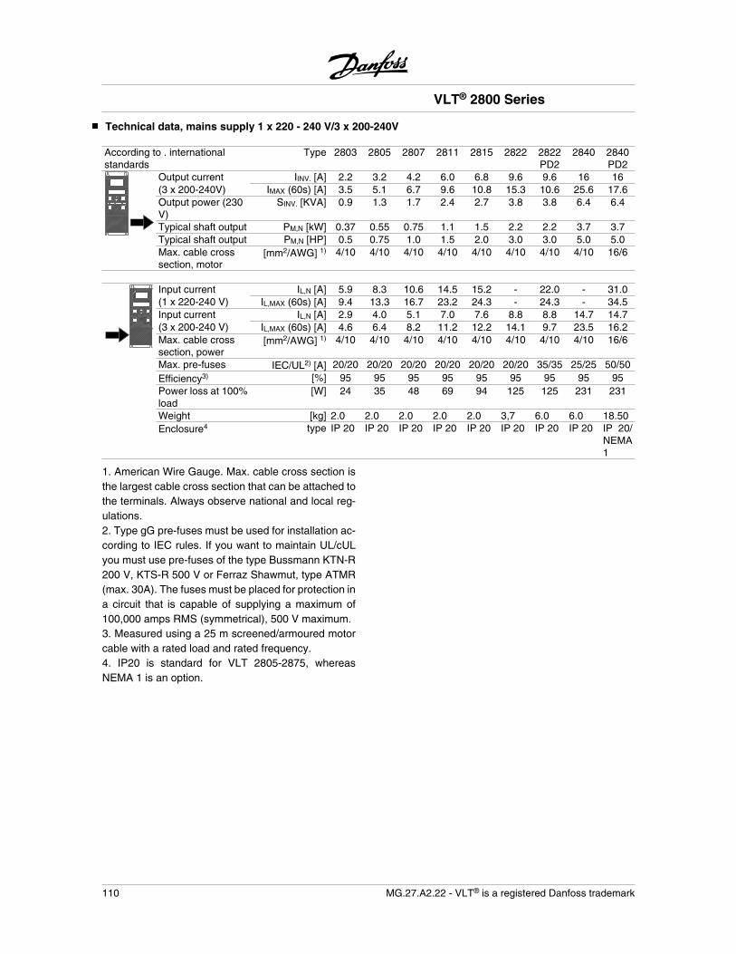
Technical data, mains supply 1 x 220 - 240 V/3 x 200-240V
According to . internationalstandards
Type 2803 2805 2807 2811 2815 2822 2822PD2
2840 2840PD2
Output current IINV. [A] 2.2 3.2 4.2 6.0 6.8 9.6 9.6 16 16(3 x 200-240V) IMAX (60s) [A] 3.5 5.1 6.7 9.6 10.8 15.3 10.6 25.6 17.6Output power (230V)
SINV. [KVA] 0.9 1.3 1.7 2.4 2.7 3.8 3.8 6.4 6.4
Typical shaft output PM,N [kW] 0.37 0.55 0.75 1.1 1.5 2.2 2.2 3.7 3.7Typical shaft output PM,N [HP] 0.5 0.75 1.0 1.5 2.0 3.0 3.0 5.0 5.0Max. cable crosssection, motor
[mm2/AWG] 1) 4/10 4/10 4/10 4/10 4/10 4/10 4/10 4/10 16/6
Input current IL,N [A] 5.9 8.3 10.6 14.5 15.2 - 22.0 - 31.0(1 x 220-240 V) IL,MAX (60s) [A] 9.4 13.3 16.7 23.2 24.3 - 24.3 - 34.5Input current IL,N [A] 2.9 4.0 5.1 7.0 7.6 8.8 8.8 14.7 14.7(3 x 200-240 V) IL,MAX (60s) [A] 4.6 6.4 8.2 11.2 12.2 14.1 9.7 23.5 16.2Max. cable crosssection, power
[mm2/AWG] 1) 4/10 4/10 4/10 4/10 4/10 4/10 4/10 4/10 16/6
Max. pre-fuses IEC/UL2) [A] 20/20 20/20 20/20 20/20 20/20 20/20 35/35 25/25 50/50Efficiency3) [%] 95 95 95 95 95 95 95 95 95Power loss at 100%load
[W] 24 35 48 69 94 125 125 231 231
Weight [kg] 2.0 2.0 2.0 2.0 2.0 3,7 6.0 6.0 18.50Enclosure4 type IP 20 IP 20 IP 20 IP 20 IP 20 IP 20 IP 20 IP 20 IP 20/
NEMA1
1. American Wire Gauge. Max. cable cross section isthe largest cable cross section that can be attached tothe terminals. Always observe national and local reg-ulations.2. Type gG pre-fuses must be used for installation ac-cording to IEC rules. If you want to maintain UL/cULyou must use pre-fuses of the type Bussmann KTN-R200 V, KTS-R 500 V or Ferraz Shawmut, type ATMR(max. 30A). The fuses must be placed for protection ina circuit that is capable of supplying a maximum of100,000 amps RMS (symmetrical), 500 V maximum.3. Measured using a 25 m screened/armoured motorcable with a rated load and rated frequency.4. IP20 is standard for VLT 2805-2875, whereasNEMA 1 is an option.
VLT® 2800 Series
110 MG.27.A2.22 - VLT® is a registered Danfoss trademark
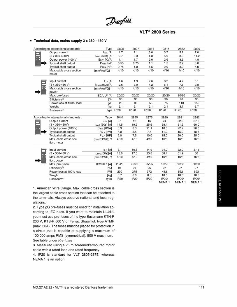
Technical data, mains supply 3 x 380 - 480 V
According to international standards Type 2805 2807 2811 2815 2822 2830Output current IINV. [A] 1.7 2.1 3.0 3.7 5.2 7.0(3 x 380-480V) IMAX (60s) [A] 2.7 3.3 4.8 5.9 8.3 11.2Output power (400 V) SINV. [KVA] 1.1 1.7 2.0 2.6 3.6 4.8Typical shaft output PM,N [kW] 0.55 0.75 1.1 1.5 2.2 3.0Typical shaft output PM,N [HP] 0.75 1.0 1.5 2.0 3.0 4.0Max. cable cross section,motor
[mm2/AWG] 1) 4/10 4/10 4/10 4/10 4/10 4/10
Input current IL,N [A] 1.6 1.9 2.6 3.2 4.7 6.1(3 x 380-480 V) IL,MAX(60s)[A] 2.6 3.0 4.2 5.1 7.5 9.8Max. cable cross section,power
[mm2/AWG] 1) 4/10 4/10 4/10 4/10 4/10 4/10
Max. pre-fuses IEC/UL2) [A] 20/20 20/20 20/20 20/20 20/20 20/20Efficiency3) [%] 96 96 96 96 96 96Power loss at 100% load [W] 28 38 55 75 110 150Weight [kg] 2.1 2.1 2.1 2.1 3.7 3.7Enclosure4 type IP 20 IP 20 IP 20 IP 20 IP 20 IP 20
According to international standards Type 2840 2855 2875 2880 2881 2882Output current IINV. [A] 9.1 12 16 24 32.0 37.5(3 x 380-480V) IMAX (60s) [A] 14.5 19.2 25.6 38.4 51.2 60.0Output power (400 V) SINV. [KVA] 6.3 8.3 11.1 16.6 22.2 26.0Typical shaft output PM,N [kW] 4.0 5.5 7.5 11.0 15.0 18.5Typical shaft output PM,N [HP] 5.0 7.5 10.0 15.0 20.0 25.0Max. cable cross sec-tion, motor
[mm2/AWG] 1) 4/10 4/10 4/10 16/6 16/6 16/6
Input current IL,N [A] 8.1 10.6 14.9 24.0 32.0 37.5(3 x 380-480 V) IL,MAX(60s)[A] 13.0 17.0 23.8 38.4 51.2 60Max. cable cross sec-tion, power
[mm2/AWG] 1) 4/10 4/10 4/10 16/6 16/6 16/6
Max. pre-fuses IEC/UL2) [A] 20/20 25/25 25/25 50/50 50/50 50/50Efficiency3) [%] 96 96 96 97 97 97Power loss at 100% load [W] 200 275 372 412 562 693Weight [kg] 3.7 6.0 6.0 18.5 18.5 18.5Enclosure4 type IP20 IP20 IP20 IP20/
NEMA 1IP20/
NEMA 1IP20/
NEMA 1
1. American Wire Gauge. Max. cable cross section isthe largest cable cross section that can be attached tothe terminals. Always observe national and local reg-ulations.2. Type gG pre-fuses must be used for installation ac-cording to IEC rules. If you want to maintain UL/cULyou must use pre-fuses of the type Bussmann KTN-R200 V, KTS-R 500 V or Ferraz Shawmut, type ATMR(max. 30A). The fuses must be placed for protection ina circuit that is capable of supplying a maximum of100,000 amps RMS (symmetrical), 500 V maximum.See table under Pre-fuses.3. Measured using a 25 m screened/armoured motorcable with a rated load and rated frequency.4. IP20 is standard for VLT 2805-2875, whereasNEMA 1 is an option.
VLT® 2800 Series
MG.27.A2.22 - VLT® is a registered Danfoss trademark 111
All
abou
t VLT
280
0
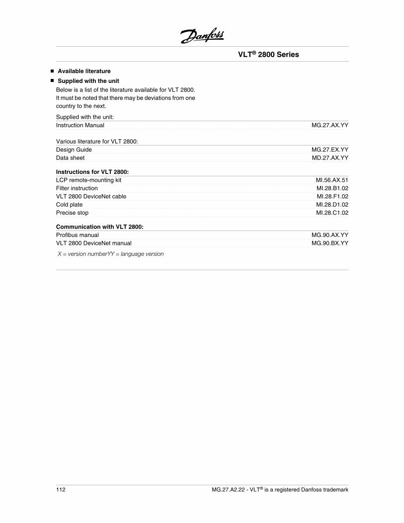
Available literature
Supplied with the unit
Below is a list of the literature available for VLT 2800.It must be noted that there may be deviations from onecountry to the next.
Supplied with the unit:Instruction Manual MG.27.AX.YY
Various literature for VLT 2800:Design Guide MG.27.EX.YYData sheet MD.27.AX.YY
Instructions for VLT 2800:LCP remote-mounting kit MI.56.AX.51Filter instruction MI.28.B1.02VLT 2800 DeviceNet cable MI.28.F1.02Cold plate MI.28.D1.02Precise stop MI.28.C1.02
Communication with VLT 2800:Profibus manual MG.90.AX.YYVLT 2800 DeviceNet manual MG.90.BX.YY
X = version numberYY = language version
VLT® 2800 Series
112 MG.27.A2.22 - VLT® is a registered Danfoss trademark

Parameter list with factory settings
PNU # Parameterdescription Factory setting 4-setup Conv.index
Datatype
001 Language English No 0 5002 Local/remote operation Remote-controlled Yes 0 5003 Local reference 000,000.000 Yes -3 4004 Active Setup Setup 1 No 0 5005 Programming Setup Active Setup No 0 5006 Setup copying No copying No 0 5007 LCP copy No copying No 0 5008 Display scaling 1.00 Yes -2 6009 Large display readout Frequency [Hz] Yes 0 5010 Small display line 1.1 Reference [%] Yes 0 5011 Small display line 1.2 Motor current [A] Yes 0 5012 Small display line 1.3 Power [kW] Yes 0 5013 Local control Remote control
as par. 100Yes 0 5
014 Local stop/reset Active Yes 0 5015 Local jog Not active Yes 0 5016 Local reversing Not active Yes 0 5017 Local reset of trip Active Yes 0 5018 Data change lock Not locked Yes 0 5019 Operating status at
power upForced stop,use saved ref.
Yes 0 5
020 Lock for Hand mode Active No 0 5024 User-defined Quick Menu Not active No 0 5025 Quick Menu Setup 000 No 0 6
4-Setup:'Yes' means that the parameter can be programmedindividually in each of the four Setups, i.e. one singleparameter can have four different data values. 'No'means that the data value will be the same in all Set-ups.
Conversion index:This number refers to a conversion figure to be usedwhen writing or reading via serial communication witha frequency converter.See Data character in Serial communication in the VLT2800 Design Guide.
Data type:Data type shows the type and length of the telegram.
Data type Description3 Integer 164 Integer 325 Unsigned 86 Unsigned 167 Unsigned 329 Text string
VLT® 2800 Series
MG.27.A2.22 - VLT® is a registered Danfoss trademark 113
All
abou
t VLT
280
0
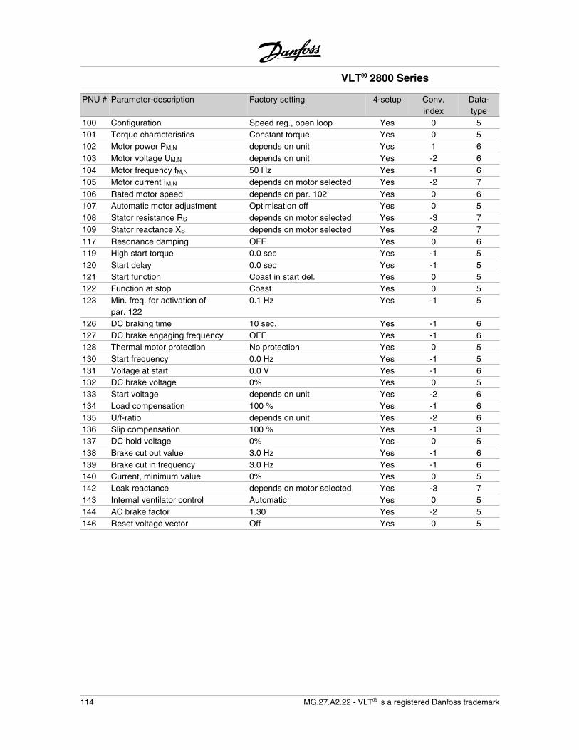
PNU # Parameter-description Factory setting 4-setup Conv.index
Data-type
100 Configuration Speed reg., open loop Yes 0 5101 Torque characteristics Constant torque Yes 0 5102 Motor power PM,N depends on unit Yes 1 6103 Motor voltage UM,N depends on unit Yes -2 6104 Motor frequency fM,N 50 Hz Yes -1 6105 Motor current IM,N depends on motor selected Yes -2 7106 Rated motor speed depends on par. 102 Yes 0 6107 Automatic motor adjustment Optimisation off Yes 0 5108 Stator resistance RS depends on motor selected Yes -3 7109 Stator reactance XS depends on motor selected Yes -2 7117 Resonance damping OFF Yes 0 6119 High start torque 0.0 sec Yes -1 5120 Start delay 0.0 sec Yes -1 5121 Start function Coast in start del. Yes 0 5122 Function at stop Coast Yes 0 5123 Min. freq. for activation of
par. 1220.1 Hz Yes -1 5
126 DC braking time 10 sec. Yes -1 6127 DC brake engaging frequency OFF Yes -1 6128 Thermal motor protection No protection Yes 0 5130 Start frequency 0.0 Hz Yes -1 5131 Voltage at start 0.0 V Yes -1 6132 DC brake voltage 0% Yes 0 5133 Start voltage depends on unit Yes -2 6134 Load compensation 100 % Yes -1 6135 U/f-ratio depends on unit Yes -2 6136 Slip compensation 100 % Yes -1 3137 DC hold voltage 0% Yes 0 5138 Brake cut out value 3.0 Hz Yes -1 6139 Brake cut in frequency 3.0 Hz Yes -1 6140 Current, minimum value 0% Yes 0 5142 Leak reactance depends on motor selected Yes -3 7143 Internal ventilator control Automatic Yes 0 5144 AC brake factor 1.30 Yes -2 5146 Reset voltage vector Off Yes 0 5
VLT® 2800 Series
114 MG.27.A2.22 - VLT® is a registered Danfoss trademark
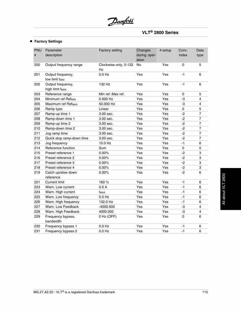
Factory Settings
PNU#
Parameterdescription
Factory setting Changesduring oper-ation
4-setup Conv.index
Datatype
200 Output frequency range Clockwise only, 0-132Hz
No Yes 0 5
201 Output frequency,low limit fMIN
0.0 Hz Yes Yes -1 6
202 Output frequency,high limit fMAX
132 Hz Yes Yes -1 6
203 Reference range Min ref.-Max ref. Yes Yes 0 5204 Minimum ref RefMIN 0.000 Hz Yes Yes -3 4205 Maximum ref RefMAX 50.000 Hz Yes Yes -3 4206 Ramp type Linear Yes Yes 0 5207 Ramp-up time 1 3.00 sec. Yes Yes -2 7208 Ramp-down time 1 3.00 sec. Yes Yes -2 7209 Ramp-up time 2 3.00 sec. Yes Yes -2 7210 Ramp-down time 2 3.00 sec. Yes Yes -2 7211 Jog ramp time 3.00 sec. Yes Yes -2 7212 Quick stop ramp-down time 3.00 sec. Yes Yes -2 7213 Jog frequency 10.0 Hz Yes Yes -1 6214 Reference function Sum Yes Yes 0 5215 Preset reference 1 0.00% Yes Yes -2 3216 Preset reference 2 0.00% Yes Yes -2 3217 Preset reference 3 0.00% Yes Yes -2 3218 Preset reference 4 0.00% Yes Yes -2 3219 Catch up/slow down
reference0.00% Yes Yes -2 6
221 Current limit 160 % Yes Yes -1 6223 Warn. Low current 0.0 A Yes Yes -1 6224 Warn. High current IMAX Yes Yes -1 6225 Warn. Low frequency 0.0 Hz Yes Yes -1 6226 Warn. High frequency 132.0 Hz Yes Yes -1 6227 Warn. Low Feedback -4000.000 Yes Yes -3 4228 Warn. High Feedback 4000.000 Yes Yes -3 4229 Frequency bypass,
bandwidth0 Hz (OFF) Yes Yes 0 6
230 Frequency bypass 1 0.0 Hz Yes Yes -1 6231 Frequency bypass 2 0.0 Hz Yes Yes -1 6
VLT® 2800 Series
MG.27.A2.22 - VLT® is a registered Danfoss trademark 115
All
abou
t VLT
280
0
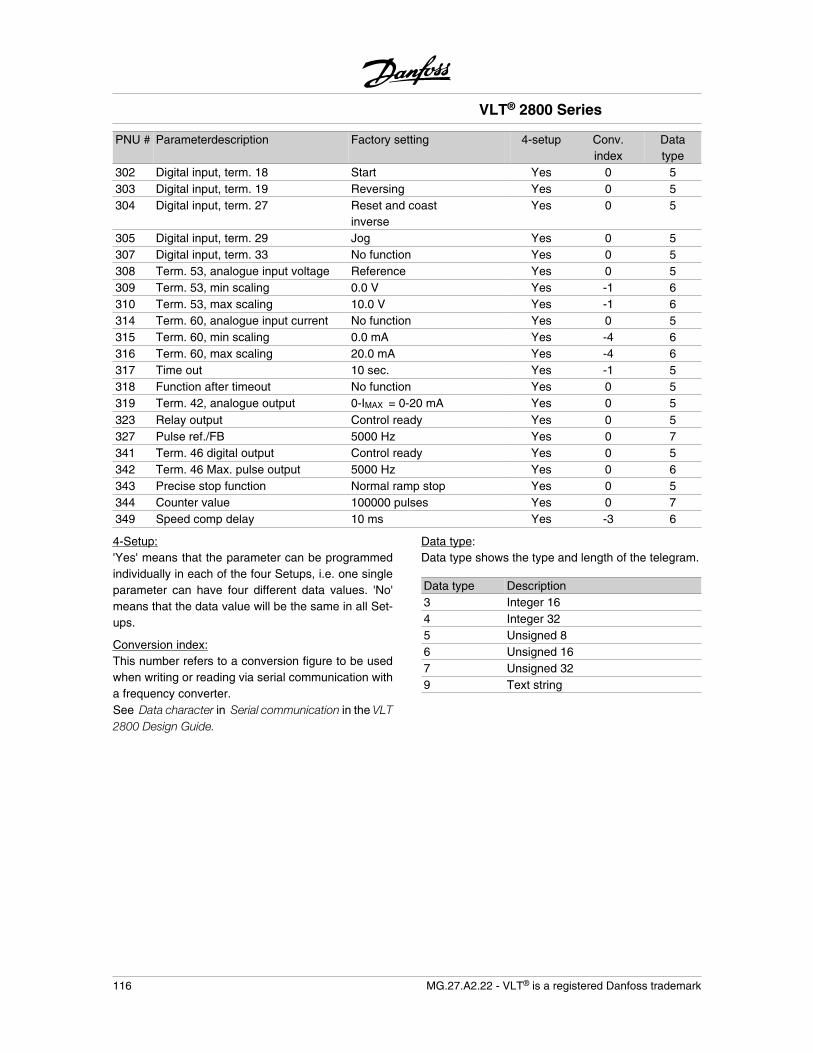
PNU # Parameterdescription Factory setting 4-setup Conv.index
Datatype
302 Digital input, term. 18 Start Yes 0 5303 Digital input, term. 19 Reversing Yes 0 5304 Digital input, term. 27 Reset and coast
inverseYes 0 5
305 Digital input, term. 29 Jog Yes 0 5307 Digital input, term. 33 No function Yes 0 5308 Term. 53, analogue input voltage Reference Yes 0 5309 Term. 53, min scaling 0.0 V Yes -1 6310 Term. 53, max scaling 10.0 V Yes -1 6314 Term. 60, analogue input current No function Yes 0 5315 Term. 60, min scaling 0.0 mA Yes -4 6316 Term. 60, max scaling 20.0 mA Yes -4 6317 Time out 10 sec. Yes -1 5318 Function after timeout No function Yes 0 5319 Term. 42, analogue output 0-IMAX = 0-20 mA Yes 0 5323 Relay output Control ready Yes 0 5327 Pulse ref./FB 5000 Hz Yes 0 7341 Term. 46 digital output Control ready Yes 0 5342 Term. 46 Max. pulse output 5000 Hz Yes 0 6343 Precise stop function Normal ramp stop Yes 0 5344 Counter value 100000 pulses Yes 0 7349 Speed comp delay 10 ms Yes -3 6
4-Setup:'Yes' means that the parameter can be programmedindividually in each of the four Setups, i.e. one singleparameter can have four different data values. 'No'means that the data value will be the same in all Set-ups.
Conversion index:This number refers to a conversion figure to be usedwhen writing or reading via serial communication witha frequency converter.See Data character in Serial communication in the VLT2800 Design Guide.
Data type:Data type shows the type and length of the telegram.
Data type Description3 Integer 164 Integer 325 Unsigned 86 Unsigned 167 Unsigned 329 Text string
VLT® 2800 Series
116 MG.27.A2.22 - VLT® is a registered Danfoss trademark
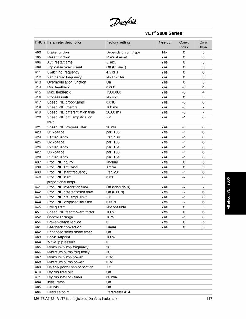
PNU # Parameter description Factory setting 4-setup Conv.index
Datatype
400 Brake function Depends on unit type No 0 5405 Reset function Manual reset Yes 0 5406 Aut. restart time 5 sec. Yes 0 5409 Trip delay overcurrent Off (61 sec.) Yes 0 5411 Switching frequency 4.5 kHz Yes 0 6412 Var. carrier frequency No LC-filter Yes 0 5413 Overmodulation function On Yes 0 5414 Min. feedback 0.000 Yes -3 4415 Max. feedback 1500.000 Yes -3 4416 Process units No unit Yes 0 5417 Speed PID propor.ampl. 0.010 Yes -3 6418 Speed PID intergra. 100 ms Yes -5 7419 Speed PID differentiation time 20.00 ms Yes -5 7420 Speed PID diff. amplification
limit5.0 Yes -1 6
421 Speed PID lowpass filter 20 ms Yes -3 6423 U1 voltage par. 103 Yes -1 6424 F1 frequency Par. 104 Yes -1 6425 U2 voltage par. 103 Yes -1 6426 F2 frequency par. 104 Yes -1 6427 U3 voltage par. 103 Yes -1 6428 F3 frequency par. 104 Yes -1 6437 Proc. PID no/inv. Normal Yes 0 5438 Proc. PID anti wind. Active Yes 0 5439 Proc. PID start frequency Par. 201 Yes -1 6440 Proc. PID start
proportional ampl.0.01 Yes -2 6
441 Proc. PID integration time Off (9999.99 s) Yes -2 7442 Proc. PID differentiation time Off (0.00 s). Yes -2 6443 Proc. PID diff. ampl. limit 5.0 Yes -1 6444 Proc. PID lowpass filter time 0.02 s Yes -2 6445 Flying start Not possible Yes 0 5451 Speed PID feedforward factor 100% Yes 0 6452 Controller range 10 % Yes -1 6456 Brake voltage reduce 0 Yes 0 5461 Feedback conversion Linear Yes 0 5462 Enhanced sleep mode timer Off463 Boost setpoint 100%464 Wakeup pressure 0465 Minimum pump frequency 20466 Maximum pump frequency 50467 Minimum pump power 0 W468 Maximum pump power 0 W469 No flow power compensation 1.2470 Dry run time out Off471 Dry run interlock timer 30 min.484 Initial ramp Off485 Fill rate Off486 Filled setpoint Parameter 414
VLT® 2800 Series
MG.27.A2.22 - VLT® is a registered Danfoss trademark 117
All
abou
t VLT
280
0
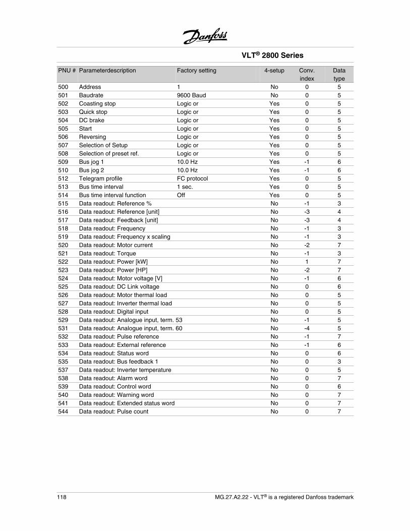
PNU # Parameterdescription Factory setting 4-setup Conv.index
Datatype
500 Address 1 No 0 5501 Baudrate 9600 Baud No 0 5502 Coasting stop Logic or Yes 0 5503 Quick stop Logic or Yes 0 5504 DC brake Logic or Yes 0 5505 Start Logic or Yes 0 5506 Reversing Logic or Yes 0 5507 Selection of Setup Logic or Yes 0 5508 Selection of preset ref. Logic or Yes 0 5509 Bus jog 1 10.0 Hz Yes -1 6510 Bus jog 2 10.0 Hz Yes -1 6512 Telegram profile FC protocol Yes 0 5513 Bus time interval 1 sec. Yes 0 5514 Bus time interval function Off Yes 0 5515 Data readout: Reference % No -1 3516 Data readout: Reference [unit] No -3 4517 Data readout: Feedback [unit] No -3 4518 Data readout: Frequency No -1 3519 Data readout: Frequency x scaling No -1 3520 Data readout: Motor current No -2 7521 Data readout: Torque No -1 3522 Data readout: Power [kW] No 1 7523 Data readout: Power [HP] No -2 7524 Data readout: Motor voltage [V] No -1 6525 Data readout: DC Link voltage No 0 6526 Data readout: Motor thermal load No 0 5527 Data readout: Inverter thermal load No 0 5528 Data readout: Digital input No 0 5529 Data readout: Analogue input, term. 53 No -1 5531 Data readout: Analogue input, term. 60 No -4 5532 Data readout: Pulse reference No -1 7533 Data readout: External reference No -1 6534 Data readout: Status word No 0 6535 Data readout: Bus feedback 1 No 0 3537 Data readout: Inverter temperature No 0 5538 Data readout: Alarm word No 0 7539 Data readout: Control word No 0 6540 Data readout: Warning word No 0 7541 Data readout: Extended status word No 0 7544 Data readout: Pulse count No 0 7
VLT® 2800 Series
118 MG.27.A2.22 - VLT® is a registered Danfoss trademark
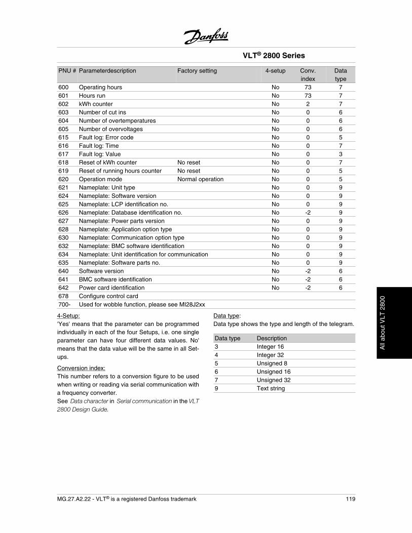
PNU # Parameterdescription Factory setting 4-setup Conv.index
Datatype
600 Operating hours No 73 7601 Hours run No 73 7602 kWh counter No 2 7603 Number of cut ins No 0 6604 Number of overtemperatures No 0 6605 Number of overvoltages No 0 6615 Fault log: Error code No 0 5616 Fault log: Time No 0 7617 Fault log: Value No 0 3618 Reset of kWh counter No reset No 0 7619 Reset of running hours counter No reset No 0 5620 Operation mode Normal operation No 0 5621 Nameplate: Unit type No 0 9624 Nameplate: Software version No 0 9625 Nameplate: LCP identification no. No 0 9626 Nameplate: Database identification no. No -2 9627 Nameplate: Power parts version No 0 9628 Nameplate: Application option type No 0 9630 Nameplate: Communication option type No 0 9632 Nameplate: BMC software identification No 0 9634 Nameplate: Unit identification for communication No 0 9635 Nameplate: Software parts no. No 0 9640 Software version No -2 6641 BMC software identification No -2 6642 Power card identification No -2 6678 Configure control card700- Used for wobble function, please see MI28J2xx
4-Setup:'Yes' means that the parameter can be programmedindividually in each of the four Setups, i.e. one singleparameter can have four different data values. No'means that the data value will be the same in all Set-ups.
Conversion index:This number refers to a conversion figure to be usedwhen writing or reading via serial communication witha frequency converter.See Data character in Serial communication in the VLT2800 Design Guide.
Data type:Data type shows the type and length of the telegram.
Data type Description3 Integer 164 Integer 325 Unsigned 86 Unsigned 167 Unsigned 329 Text string
VLT® 2800 Series
MG.27.A2.22 - VLT® is a registered Danfoss trademark 119
All
abou
t VLT
280
0
VLT® 2800 Series
120 MG.27.A2.22 - VLT® is a registered Danfoss trademark

Rev. 2007-06-11
www.danfoss.com/drives
195R0027 MG27A222
*MG27A222*
MG
27A222
VLT
2800 Instru
ction
Man
ual