instruction manual - hfgp.com · the meter startup self test is automatic. if the device does not...
TRANSCRIPT

Hastings Hot Line Tools
Digital Voltage Phase Meter Catalog Number 6702
Instruction Manual


TABLE OF CONTENTS
SAFETY ................................................................. 1
FEATURES ............................................................ 2 OPERATING INSTRUCTIONS ............................ 4 BATTERY REPLACEMENT ................................ 9
TROUBLESHOOTING ........................................ 10 SPECIFICATIONS ............................................... 11
WARRANTY ....................................................... 12


1
SAFETY
The Meter must only be used by trained personnel
familiar with the use of such devices. This device is
designed for use with high voltage which is lethal.
Improper use may result in serious injury or death.
Always follow OSHA and your company work
procedures when using the Meter.
Always use the Meter with an appropriate hot stick
length for the potential being tested.
The Meter startup self test is automatic. If the device
does not complete the startup self test, do not
attempt to use it. (See Page 5 Step 2.0).
The body of the Meter will be at an elevated
potential. Use caution when operating the Meter in
the vicinity of grounded or energized objects.
The Meter is only intended for operation on 50 Hz
and 60 Hz AC power systems and DC voltages up to
4 kV.
Hi-Pot mode will only work with the Hi-Pot Adapter
installed and with the Meter in Hi-Pot mode (see
page 6).

2
FEATURES
Mode
Selection
Button
Mode Setting
Voltage Range
Maximum
Voltage Bar Graph
Voltage Display
Reading
Top view of Meter
Front view of Meter
Power On/Off
& Light On/Off
Button

3
FEATURES
Auto self test and battery voltage level check
during startup.
Large digital display with backlight on/off
function.
Three modes of operation are available: AC,
Hi-Pot (Hi-Pot Adapter must be installed to use
in Hi-Pot mode, see page 6), and DC.
Maximum value of voltage range is displayed.
Long battery life from three “AA” batteries.
High quality rugged extruded aluminum
enclosure.

4
OPERATING INSTRUCTIONS
1.0 Prepare to Use
Remove the Meter from its storage case and inspect for
damage.
The Meter consists of high voltage resistors
encapsulated inside two fiberglass housings. These
resistors are connected together with a coiled cord. A
digital display is attached to one of the encapsulated
resistor housings.
Attach each encapsulated resistor to a hot stick of
appropriate length for the voltages to be tested.
If the Meter is to be used on voltages of over 40 kV, the
proper number of Extension Resistors (Cat. No. 6703)
must be attached to probe ends of the encapsulated
resistors. To attach Extension Resistors, remove probes
from encapsulated resistors, attach Extension Resistors
to encapsulated resistors, and re-assemble probes to end
of Extension Resistors. The Extension Resistors are
used in pairs, attaching one to each end of the Meter
sticks. To determine number of Extension Resistors
required, see table below. Voltage range on the Meter
will calibrate to correct voltage range during startup, if
the ends of Extension Resistors remain in contact with
each other during startup.
Number of Extension
Resistor Pairs Required Voltage Range
1 80 kV
2 120 kV
3 160 kV
4 200 kV
5 240 kV
Table 1: Extension Resistor Pairs for systems above 40 kV

5
2.0 Perform and observe “SELF TEST” result
With the Meter turned off, press and release the
ON/LIGHT/OFF button once to turn the Meter on and
begin self test. Before powering on, position the Meter
to keep the probe ends in contact with each other.
The Meter will perform self test and battery
voltage check.
If the battery voltage is low, this will be
displayed during the first screen of startup, by
“Battery Voltage: Low”. Batteries must be
replaced if this message is observed.
The Meter will default to AC when powered on.
After passing the self test, if the probe ends of
the Meter are not connected, the Meter display
will prompt for the probe ends to be connected,
and press the AC/HIPOT/DC button. This will
determine the number of Extension Resistors
connected to the Meter. The Meter defaults to
40 kV.
3.0 Turn backlight on/off, select Mode of Operation
After the Meter is powered on, pressing and holding the
ON/LIGHT/OFF button will turn on the backlight.
Release ON/LIGHT/OFF once the backlight turns on.
Pressing and holding ON/LIGHT/OFF again will turn
the backlight off. Pressing and holding the
AC/HIPOT/DC button will turn on the mode selection
menu. With the mode selection menu on, pressing
AC/HIPOT/DC will cycle through the available modes.
Once the desired mode is selected, the Meter will return
to the voltage reading mode.
Note: to use the Meter in Hi-Pot mode, a Hi-Pot
Adapter must be installed (see page 6).

6
4.0 Contact Meter with voltage source
When a potential is contacted by both probes, the
resulting voltage will display numerically on the display,
and also graphically on the voltage bar graph.
If a voltage potential is contacted and the display flashes
“++++”, the Meter has read a voltage higher than the
allowable range. If a voltage potential is contacted and
the display flashes “EEEE”, the Meter is in the wrong
mode for the power system being tested.
5.0 Accessories
As previously stated in Section 1.0, Prepare to Use,
Extension Resistors must be used in conjunction with the
Meter on systems above 40 kV. See section 1.0 for
instructions on this procedure.
Underground bushing adapters for 35 kV Elastimold,
and all 15 and 25 kV bushings (Cat. No. 6702-1), and for
35 kV RTE bushings (Cat. No. 6702-3) can be attached
to the Meter by removing the supplied probe and
replacing it with the appropriate adapter.
A DC Hi-Pot Adapter (Cat. No. 6702-2) is available
which allows the testing of underground cable by
rectifying the available system voltage and charging the
cable to a DC voltage equal to the peak AC voltage
supplied. While the DC voltage is high enough to test
the cable, the current is limited by the Meter. In the
event the cable is defective or grounds have been left on,
fault currents will not result. Please see DC Hi-Pot
instructions for operating the 6702 Meter with the DC
Hi-Pot Adapter installed.

7
6.0 Shutdown
To turn the Meter off, press & hold the ON/LIGHT/OFF
pushbutton until the display shuts off, indicating meter
shutdown. The backlight will turn on during shutdown
of the Meter.
The Meter will automatically shut down after 40 minutes
if no voltage potential is detected.

8
Operating Instructions Flow Chart
Perform Self Test
Attach to Hot Stick
Source
Manual Shutdown
Auto Shutdown After 40 minutes
Result
Select Operating Mode
Inspect Unit
Select Backlight On/Off
Attach Adapters Attach Extension Resistors
Contact Voltage Potential
Source

9
BATTERY REPLACEMENT
The Meter uses three “AA” cells. These may be either
Alkaline or NiMH.
The batteries are accessed by removing the back panel of
the Meter.
10
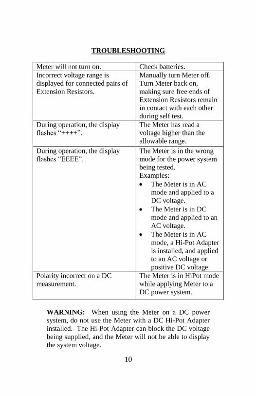
TROUBLESHOOTING
Meter will not turn on. Check batteries. Incorrect voltage range is
displayed for connected pairs of
Extension Resistors.
Manually turn Meter off.
Turn Meter back on,
making sure free ends of
Extension Resistors remain
in contact with each other
during self test. During operation, the display
flashes “++++”.
The Meter has read a
voltage higher than the
allowable range.
During operation, the display
flashes “EEEE”.
The Meter is in the wrong
mode for the power system
being tested.
Examples:
The Meter is in AC
mode and applied to a
DC voltage.
The Meter is in DC
mode and applied to an
AC voltage.
The Meter is in AC
mode, a Hi-Pot Adapter
is installed, and applied
to an AC voltage or
positive DC voltage.
Polarity incorrect on a DC
measurement.
The Meter is in HiPot mode
while applying Meter to a
DC power system.
WARNING: When using the Meter on a DC power
system, do not use the Meter with a DC Hi-Pot Adapter
installed. The Hi-Pot Adapter can block the DC voltage
being supplied, and the Meter will not be able to display
the system voltage.

11
SPECIFICATIONS
Line Voltage Mode 0 – 40 kV AC
0 – 4 kV DC
Operating frequency 50 – 60 Hz AC, DC
Batteries 3 x 1.5V Alkaline or NiMH “AA”
Battery Life 24 hrs (backlight on continuously)
14 days (backlight off continuously)
Operating
Temperature
-40ºF to 122ºF
Storage Temperature -40ºF to 158ºF
Weight 3.8lbs (without probes)
4.0 lbs (with probes)
Accuracy 1% *
* Accuracy is affected in the field by the proximity of
other conductive objects in the vicinity of this Meter.
Keeping the cord away from other objects will improve
accuracy.

12
WARRANTY
HASTINGS warrants the catalog number 6702 Digital
Voltage Phase Meter to be free from manufacturing
defects, for a period of one year from the date of
purchase to the original owner. At the discretion of the
company, units returned under this warranty shall be
either repaired or replaced at no cost to the customer.
This warranty will not apply to normal wear and tear or
inappropriate use, alteration or abuse of the device.
For warranty or repair send units to:
HASTINGS Hot Line Tools
770 South Cook Road
Hastings, MI 49058
Attn: Warranty Repair Department
For Enquiries or technical assistance call:
269-945-9541 or FAX 269-945-4623
P31428-R2
