instruction manual high throughput diffusion pumps …
TRANSCRIPT

DR
AF
T 7
/18
/14
INSTRUCTION MANUAL
Vacuum Products Division
High Throughput Diffusion Pumps
HS-16HS-20HS-32NHS-35
Part No. 699901140
Rev. E
June 2014

DR
AF
T 7
/18
/14
High Throughput Diffusion Pumps
Viton® is a registered trademark of E. I du Pont de Nemours and Company.
Copyright 2014Agilent, Inc.

High Throughput Diffusion Pumps
DR
AF
T 7
/18
/14
Contents
Diffusion Pump Hazards . . . . . . . . . . . . . . . . . . . . . . . 7Explosion . . . . . . . . . . . . . . . . . . . . . . . . . . . . . . . 8Pressurization Hazards . . . . . . . . . . . . . . . . . . . . 9Dangerous Substances . . . . . . . . . . . . . . . . . . . . . 9High Temperatures . . . . . . . . . . . . . . . . . . . . . . 10High Voltages . . . . . . . . . . . . . . . . . . . . . . . . . . 10Large Equipment and Heavy Weights . . . . . . . . 10
Diffusion Pump Basics . . . . . . . . . . . . . . . . . . . . . . . . 11Pump Operation . . . . . . . . . . . . . . . . . . . . . . . . . . 11Operating Characteristics . . . . . . . . . . . . . . . . . . . 11Pump Air Speed and Throughput . . . . . . . . . . . . . . 14Physical Specifications . . . . . . . . . . . . . . . . . . . . . 15Unpacking . . . . . . . . . . . . . . . . . . . . . . . . . . . . . . 19Setup . . . . . . . . . . . . . . . . . . . . . . . . . . . . . . . . . . . 19
Assembly . . . . . . . . . . . . . . . . . . . . . . . . . . . . . . 19Cleaning a New Pump . . . . . . . . . . . . . . . . . . . . . 20
Cleaning Safety . . . . . . . . . . . . . . . . . . . . . . . . . 20Disassembly for Initial Cleaning . . . . . . . . . . . . 20Reassembly After Initial Cleaning . . . . . . . . . . . 20
System and Utility Connections . . . . . . . . . . . . . . . . . 21Vacuum Connections . . . . . . . . . . . . . . . . . . . . . . 21Cooling Water . . . . . . . . . . . . . . . . . . . . . . . . . . . . 21Electrical Connections . . . . . . . . . . . . . . . . . . . . . . 24Overheating: Detection by Thermal Switches . . . . 25
Initial Vacuum Test . . . . . . . . . . . . . . . . . . . . . . . . . . 36Adding or Changing Pump Fluid . . . . . . . . . . . . . . 37
Information on Fluid and DP Performance . . . . . 37
Operation . . . . . . . . . . . . . . . . . . . . . . . . . . . . . . . . . 39Startup Procedure . . . . . . . . . . . . . . . . . . . . . . . . . 40
Humid Environments . . . . . . . . . . . . . . . . . . . . . 40Shutdown Procedure . . . . . . . . . . . . . . . . . . . . . . . 40
Maintenance . . . . . . . . . . . . . . . . . . . . . . . . . . . . . . . 41Periodic Inspections . . . . . . . . . . . . . . . . . . . . . . . 41Cleaning . . . . . . . . . . . . . . . . . . . . . . . . . . . . . . . . 42
Cleaning Safety . . . . . . . . . . . . . . . . . . . . . . . . . 42Disassembly and Reassembly Procedures . . . . . . . 43
Cold Cap . . . . . . . . . . . . . . . . . . . . . . . . . . . . . . 43Jet Assemblies . . . . . . . . . . . . . . . . . . . . . . . . . . 44Heater Replacement Procedure . . . . . . . . . . . . . 50
Troubleshooting. . . . . . . . . . . . . . . . . . . . . . . . . . . . . 51Leakage . . . . . . . . . . . . . . . . . . . . . . . . . . . . . . . . . 51Outgassing . . . . . . . . . . . . . . . . . . . . . . . . . . . . . . 51Poor Pump or System Performance . . . . . . . . . . . . 52
Replacement Parts . . . . . . . . . . . . . . . . . . . . . . . . . . . 53
3

High Throughput Diffusion Pumps D
RA
FT
7/1
8/1
4
List of FiguresFigure Caption Page
1 HS-20 Diffusion Pump . . . . . . . . . . . . . . . . . 112 HS-16 Speed and Throughput Curves, 8.1 kW .
143 HS-20 Speed and Throughput Curves . . . . . 144 HS-32 Speed and Throughput Curves . . . . . 145 NHS-35 Speed and Throughput Curves . . . . 146 HS-16 Outline with ASA Flanges . . . . . . . . 157 HS-20 Outline with ASA Flanges . . . . . . . . 168 HS-32 Outline with ASA Flanges . . . . . . . . 179 NHS-35 Outline with ASA Flanges. . . . . . . 1810 HS-16/20 Cooling Water Connections . . . . . 2111 HS-32/NHS-35 Cooling Water Connections. 2212 HS-16 3-Phase Delta Circuit . . . . . . . . . . . 2613 HS-16 3-Phase WYE Circuit . . . . . . . . . . . . 2714 HS-20 3-Phase Delta Parallel Circuit . . . . . 2815 HS-20 3-Phase WYE Parallel Circuit . . . . . 2916 HS-32 3-Phase Delta Parallel Circuit . . . . . 3017 HS-32 3-Phase WYE Parallel Circuit . . . . . 3118 HS-32 3-Phase Delta Series Circuit . . . . . . 3219 NHS-35 3-Phase Delta Parallel Circuit . . . . 3320 NHS-35 3-Phase WYE Parallel Circuit . . . . 3421 NHS-35 3-Phase Delta Series Circuit . . . . . 3522 Sight Glass Assembly . . . . . . . . . . . . . . . . . . 3823 Cold Cap Assembly . . . . . . . . . . . . . . . . . . 4324 HS-16 Jet Assembly . . . . . . . . . . . . . . . . . . . 4425 HS-20 Jet Assembly . . . . . . . . . . . . . . . . . . . 4526 Jet Coupling Detail. . . . . . . . . . . . . . . . . . . 4627 HS-32 Jet Assembly . . . . . . . . . . . . . . . . . . . 4728 NHS-35 Jet Assembly. . . . . . . . . . . . . . . . . . 4929 Heater Element Assembly . . . . . . . . . . . . . . 50
List of TablesTable Title Page
1 General Hazards . . . . . . . . . . . . . . . . . . . . . . 72 Explosive Conditions. . . . . . . . . . . . . . . . . . . 83 Pressurization Hazards . . . . . . . . . . . . . . . . . 94 Operating Specifications . . . . . . . . . . . . . . . 125 HS-16: Dimensions and Weights. . . . . . . . . 156 HS-16 Flange Dimensions. . . . . . . . . . . . . . 157 HS-20: Dimensions and Weights. . . . . . . . . 168 HS-20 Flange Dimensions. . . . . . . . . . . . . . 169 HS-32: Dimensions and Weights. . . . . . . . . 1710 HS-32 Flange Dimensions. . . . . . . . . . . . . . 1711 NHS-35: Dimensions and Weights . . . . . . . 1812 NHS-35 Flange Dimensions . . . . . . . . . . . . 1813 Wiring Diagram Locations . . . . . . . . . . . . . 2414 Thermal Cutout Temperatures . . . . . . . . . . . 2515 HS -16 3 Phase Delta . . . . . . . . . . . . . . . . 2616 HS -16 3 Phase WYE . . . . . . . . . . . . . . . . 2717 HS -20 3-Phase Delta Parallel . . . . . . . . . 2818 HS -20 3-Phase WYE Parallel . . . . . . . . . . 2919 HS -32 3-Phase Delta Parallel . . . . . . . . . . . 3020 HS -32 3-Phase WYE Parallel . . . . . . . . . . . 3121 HS -32 3-Phase Delta Series . . . . . . . . . . . . 3222 NHS-35 3-Phase Delta Parallel . . . . . . . . . . 3323 NHS-35 3-Phase WYE Parallel . . . . . . . . . . 3424 NHS-35 3-Phase Delta Series . . . . . . . . . . . 3525 Troubleshooting Guide . . . . . . . . . . . . . . . . 5226 HS-16 Replacement Parts . . . . . . . . . . . . . . 5327 HS-20 Replacement Parts . . . . . . . . . . . . . . 5428 HS-32 Replacement Parts . . . . . . . . . . . . . . 5529 NHS-35 Replacement Parts . . . . . . . . . . . . . 56
4
High Throughput Diffusion Pumps
DR
AF
T 7
/18
/14
Preface
WarrantyProducts manufactured by Seller are warranted againstdefects in materials and workmanship for twelve (12)months from date of shipment thereof to Customer, andSeller’s liability under valid warranty claims is limited, atthe option of Seller, to repair, replacement, or refund anequitable portion of the purchase price of the Product.Items expendable in normal use are not covered by thiswarranty. All warranty replacement or repair of parts shallbe limited to equipment malfunctions which, in the soleopinion of Seller, are due or traceable to defects in origi-nal materials or workmanship. All obligations of Sellerunder this warranty shall cease in the event of abuse,accident, alteration, misuse, or neglect of the equipment.In-warranty repaired or replaced parts are warranted onlyfor the remaining unexpired portion of the original war-ranty period applicable to the repaired or replaced parts.After expiration of the applicable warranty period, Cus-tomer shall be charged at the then current prices for parts,labor, and transportation.
When products are used with toxic chemicals, or in anatmosphere that is dangerous to the health of humans, oris environmentally unsafe, it will be the responsibility ofthe Customer to have the product cleaned by an indepen-dent agency skilled and approved in handling and clean-ing contaminated materials before the product will beaccepted by Agilent, Inc. for repair and/or replacement.
Reasonable care must be used to avoid hazards. Seller expressly disclaims responsibility for loss or damage caused by use of its Products other than in accordance with proper operating procedures.
Except as stated herein, Seller makes no warranty, expressor implied (either in fact or by operation of law), statutoryor otherwise; and, except as stated herein, Seller shallhave no liability under any warranty, express or implied(either in fact or by operation of law), statutory or other-wise. Statements made by any person, including repre-sentatives of Seller, which are inconsistent or in conflictwith the terms of this warranty shall not be binding uponSeller unless reduced to writing and approved by an offi-cer of Seller.
DisclaimerOperation and maintenance of this equipment involvesserious risk. It is the responsibility of the user to maintainsafe operating conditions at all times. Agilent assumes noliability for personal injury or damage resulting fromoperation or service of the equipment.
Agilent has no control over the use of this equipment andis not responsible for personal injury or damage resultingfrom its use. The safe use and disposal of hazardous orpotentially hazardous materials of any kind is the soleresponsibility of the user. Observe all WARNINGS andCAUTIONS to minimize the serious hazards involved.
It is the sole responsibility of the users of Agilent equip-ment to comply with all local, state and federal safetyrequirements (laws and regulations) applicable to theirsystem. Employ the services of an industrial hygienistand/or a qualified chemical safety engineer in order toensure safe installation and use.
Warranty Replacement and AdjustmentAll claims under warranty must be made promptly after occurrence of circumstances giving rise thereto, and must be received within the applicable warranty period by Seller or its authorized representative. Such claims should include the Product serial number, the date of shipment, and a full description of the circumstances giving rise to the claim. Before any Products are returned for repair and/or adjustment, written authorization from Seller or its authorized representative for the return and instructions as to how and where these Products should be returned must be obtained. Any Product returned to Seller for examination shall be prepaid via the means of transportation indicated as acceptable by Seller. Seller reserves the right to reject any warranty claim not promptly reported and any warranty claim on any item that has been altered or has been returned by non-acceptable means of transportation. When any Product is returned for examination and inspection, or for any other reason, Customer shall be responsible for all damage resulting from improper packing or handling, and for loss in transit, notwithstanding any defect or non-conformity in the Product. In all cases, Seller has the sole responsibility for determining the cause and nature of failure, and Seller’s determination with regard thereto shall be final.
If it is found that Seller’s Product has been returned without cause and is still serviceable, Customer will be notified and the Product returned at its expense; in addition, a charge for testing and examination may be made on Products so returned.
5

High Throughput Diffusion Pumps D
RA
FT
7/1
8/1
4
Instructions for UseThis equipment is designed for use by professionals. The user should read this instruction manual and any other additionalinformation supplied by Agilent before operating the equipment. Agilent will not be held responsible for any events thatoccur due to non-compliance with these instructions, improper use by untrained persons, non-authorized interferencewith the equipment, or any action contrary to that proved for by specific national standards.
This manual uses the following standard safety protocol:
WARNING The warnings are for attracting the attention of the operator to a particular procedure or practice which, if not followed correctly, could lead to serious injury.
CAUTION The cautions are displayed before procedures, which if not followed, could cause damage to the equipment.
NOTE The notes contain important information taken from the text.
6

High Throughput Diffusion Pumps
DR
AF
T 7
/18
/14
Diffusion Pump Hazards
Designers of systems utilizing diffusion pumps must design out hazards wherever possible. For hazards that cannot bedesigned out, warnings, procedures, and instructions on proper use and servicing are provided. Please use guards, safetyfeatures, and interlocks as recommended.
Refer to Table 1 for a list of general hazards and recommended actions, Table 2 on page 8 for a list of prohibited actionsthat can result in explosions, and Table 3 on page 9 for a list of pressurization hazards that can result in damage toequipment.
THE INSTALLATION, OPERATION, AND SERVICING OF DIFFUSION PUMPS INVOLVES ONE OR MORE OF THE FOLLOWING HAZARDS, ANY ONE OF WHICH IN THE ABSENCE OF SAFE OPERATING PRACTICES AND PRECAUTIONS, COULD POTENTIALLY RESULT IN DEATH OR SERIOUS HARM TO PERSONNEL.
Table 1 General Hazards
Hazard Suggested Corrective Action
Loss of utility: water and/or electricity Provide sufficient backup water and power supply as necessary to effect a safe shutdown under worst case conditions
Overpressure in foreline Provide an interlock to ensure that the power supply to the pump heater cannot be activated if the foreline pump is not running and/or the pressure in foreline is above 0.5 Torr (0.67 mbar)
Overtemperature Fit temperature sensors and pump fluid level sensors with feedback to an interlock on the heater power supply
Insufficient water flow through the main cooling coils Use water flow sensor and feedback to interlock the heater power supply
Water trapped between inlet and outlet of Quick Cool coil, or liquid nitrogen trapped between inlet and outlet of liquid nitrogen trap
Provide vent or pressure relief valves for both Quick Cool coil and liquid nitrogen trap
Loss of electrical ground integrity Incorporate ground fault interrupt circuit into heater power supply
Positive pressure in pumping system Integrate pressure relief valve in vacuum system to ensure system pressure does not exceed 1 atmosphere
High voltage Prevent personnel contact with high voltages; design and attach warnings
Toxicity and Corrosivity Vent toxic and/or corrosive gases to a safe location; ensure adequate dilution or scrubbing to safe levels; take all action required to meet air quality standards
Explosion Integrate pressure relief valves
Do not use hydrocarbon-based pumping fluids
7

High Throughput Diffusion Pumps D
RA
FT
7/1
8/1
4
Explosion❑ Operation of the diffusion pump without continuous
evacuation below 0.5 Torr (0.67 mbar), or without coolant and introducing a strong oxidizer (such as air) or explosive vapors or powders or materials which may react with pumping fluids in a hot pump (above 300 °F or 150 °C) can cause an explosion. Such an explosion can violently expel valves and other hardware, slam open doors that are not designed for appropriate pressure relief, or burst other components of the vacuum system. Serious injury or death may result from expelled parts, doors, shrapnel, and shock waves.
❑ Three elements are required for explosion: fuel, oxi-dizer, and an ignition. A combination of temperature and pressure can be a source of ignition. Most diffu-sion pump fluids are fuels. Hydrocarbon fluids are more prone to oxidize and explode than synthetic silicone-based fluid. The oxidizer can be air, which can be introduced by a leak, deliberately brought in via a process, or inadvertently admitted by operator error.Oxygen and other strong oxidizers are even more dangerous than air. Certain conditions of temperature and pressure can cause a combustible mixture to explode. The larger the diffusion pump, the greater the risk of explosion and the greater the risk of dam-age and injury. Never operate large diffusion pumps utilizing hydrocarbon oils without a complete safety analysis for the entire system and for the application.
❑ Explosion and Fire from Acetone and Alcohol: Diffu-sion pumps are typically cleaned with acetone and alcohol. When combined with air, oxygen, and other oxides, alcohol and most other solvents are very flammable and explosive. Never permit any trace of these cleaners to remain in or on the pump. Always remove all traces of alcohol and acetone and other cleaners with clean, dry, oil-free compressed air.
Never operate a large diffusion pump under the condi-tions listed in Table 2. Any of these situations increasesthe probability of an explosion.
Table 2 Explosive Conditions
Prohibited ActionExplosion-Causing
Condition
Do not run pump without cooling water
Overtemperature
Do not run pump with low level of pump fluid
Overtemperature
Do not run pump without proper backing or holding pump
Overpressure
Do not run pump when not evacuated below 0.5 Torr (0.67 mbar)
Overpressure
Do not admit air to, or rough through, a pump with hot boiler
Overpressure plus strong oxidizer
Do not open drain or fill plug while pump is under vacuum, especially when it is hot
Overpressure plus strong oxidizer
Do not contaminate pump with explosive vapors
Lower explosive threshold of gas mixtures
Do not remove, defeat, or override safety counter-measures such as pressure and thermal switches and valve sequencer interlocks
Overtemperature, overpressure, more combustible mixtures
Do not machine or weld any part of the pump without removing all fluid or solvent residue in pump
Source of ignition
Do not use unsuitable pumping fluid
Lower explosive threshold of gas mixture
8

High Throughput Diffusion Pumps
DR
AF
T 7
/18
/14
Pressurization Hazards ❑ Large vacuum pumps and their components are
designed for vacuum service; they are not designed to be pressurized which could cause them to burst possibly expelling shrapnel at lethal velocities. Serious accidents have been caused by intentional pressurization of vacuum systems and their compo-nents.
❑ Never pressurize any part of a vacuum system for test or any other purpose.
❑ Always provide pressure relief when designing diffusion pumps into systems and ensure that pressure relief motion is limited to safe envelopes.
❑ Never permit the hazards in Table 3 to develop.
❑ Pressure Relief Devices: Systems must be designed with pressure relief devices to provide safe pressure relief from internal explosions. Always recognize that safety devices can fail or malfunction; provide redun-dant protection by installing devices having different failure modes, failure mechanisms, and failure causes. Be certain that exhaust duct materials are capable of withstanding the corrosivity, temperature, and pressure of exhausted products.
Dangerous Substances❑ Chemical Dangers of Acetone and Alcohol: Diffusion
pumps are typically cleaned with acetone or alcohol. Acetone, alcohol, and most other solvents are irri-tants, narcotics, and depressants, and/or carcino-genic. Their inhalation and ingestion may produce serious effects. Even absorption through the skin can result in moderate toxicity. Always ensure that clean-ing operations are performed in large, well-ventilated rooms. Use of self-contained breathing apparatus may be necessary depending upon the solvent type and vapor concentration in surrounding air.
❑ Poisonous and Corrosive Compounds: When pump-ing poisonous, reactive, and/or corrosive gas, vapors, or chemicals, proper operation and regeneration do not always ensure that all hazardous materials have been totally removed. If hazardous gas, vapors, chemicals, or combustible mixtures are pumped, suf-ficient quantities may exist during operation or remain after regeneration to cause severe injury or death.
❑ Pump Fluids: Overheating the pump fluid, exposing it to air or reactive materials, or overpressurizing it above the normal operating range, approximately 1x10³ Torr (1.3x10³ mbar) decomposes the fluid and possibly makes it toxic. This is especially true of backstreamed mechanical pump fluids which are more volatile (unstable). Overheating of accidentally introduced or backstreamed mechanical pump fluids cannot be protected against by thermal switches which are set for diffusion pump fluid.
❑ Process Gasses: Process gasses are frequently toxic, flammable, corrosive, explosive, or otherwise reac-tive. Agilent has no control over the types of gasses passing through the user’s diffusion pump as these are entirely under the control of the process user and/or the hardware systems integrator. Since these gasses can cause serious injury or death, it is very important to plumb the exhaust of the pump to the facility’s hazardous gas exhaust system which incorporates appropriate filters, scrubbers and similar components to ensure that the exhaust meets all air and water pol-lution control regulations.
Table 3 Pressurization Hazards
Prohibited Action Result
Do not block inlet or vent of liquid nitrogen trap and lines
LN2 trap and/or lines burst
Do not close isolation valves at inlet and discharge of main water cooling coils when pump is heated
Water turns to steam and bursts coils
Do not pressurize the pump body (above 1 atm.)
Body of pump bursts
Do not make a hole through the vacuum wall
Loss of structural integrity of wall
9

High Throughput Diffusion Pumps D
RA
FT
7/1
8/1
4
High Temperatures❑ Hot Surfaces: Boiler temperatures reach 530 °F
(275 °C) which can cause serious burns. Always ensure that surfaces have cooled to near room temperature before touching them.
❑ Hot Cooling Water and Steam: The water used to cool the pump can reach scalding temperatures. Touching or rupture of the cooling surface can cause serious burns. Water left inside Quick Cool coils from previous use turns to steam when the pump is reheated. This steam must be allowed to escape with-out contacting personnel. Whenever possible, design the water system with interlock valves so that power cannot be applied to the pump unless water is flow-ing in the main cooling coils (not Quick Cool coils).
High Voltages❑ Diffusion pump heaters operate at voltages high
enough to kill. Design systems to prevent personnel contact with high voltages. Securely attach promi-nent hazard warnings. Personnel should always break the primary circuit to the power supply when direct access to the heater or wiring is required.
Large Equipment and Heavy Weights❑ The lifting and moving of large diffusion pumps
requires power-assisted equipment and the use of trained moving and installation personnel to avoid dropping, slipping, and overturning the pump. Pumps weigh in excess of 500 lbs (226.8 kg) and are 3 to 6 feet in their largest dimension (1 to 2 meters). Their mishandling can cause severe injury. Check the weight of the equipment before lifting and assure that the power-assist device is adequate for the task. Do not stand under the equipment being lifted and moved.
10

High Throughput Diffusion Pumps
DR
AF
T 7
/18
/14
Diffusion Pump Basics
Diffusion pumps are used where throughput for heavy gasloads is important. The diffusion pumps begin to work atapproximately 103 Torr after a mechanical backingpump has exhausted most of the air in the system.
Figure 1 HS-20 Diffusion Pump
There are no moving parts in a diffusion pump, the heartof which is the multistage jet assembly, a group of con-centric cylinders that are capped to leave small openingsthrough which vapor can be deflected down and outtoward the pump walls. A cold cap, mounted on top ofthe jet assembly helps keep pump fluid vapor out of theevacuation chamber. The pumps are water-cooled.
The vacuum fluid heater is mounted at the bottom of thepump body. The pumps also have a fill and drain assem-bly, and thermal protection switches. The inlet is at thetop, and the exhaust is through the foreline.
Pump OperationThe diffusion pump works by heating the pump fluid to itsboiling point. The vapors travel upward inside the jetassembly and are accelerated out and downward throughthe jet nozzles toward the cool outer walls of the pump,where the vapor condenses back into a fluid. As the vaporpasses the inlet, it picks up elements of the gas to beexhausted and carries them to the ejector and out of thepump via the foreline. The pump’s ability to reach lowpressures is governed in part by the inlet size. The gasmigrates by thermal motion and is captured and expelled,thus lowering the pressure in the evacuation vessel.
Large diffusion pumps achieve a vacuum using afive-stage jet assembly consisting of four diffusion stagesand one ejector stage. The cold cap and body are watercooled. Optional stainless steel Quick Cool coils quicklysuppress boiling by cooling the heater; they require anindependently valved water supply.
Operating CharacteristicsThe Operating Characteristics of the large diffusionpumps are given in Table 4 on page 12. The graphs inFigure 2 through Figure 5 on page 14 show air speed andthroughput as a function of inlet pressure. The dimensionsof the inlet flange that connects to the system to be evacu-ated are given in Table 6 on page 15 through Table 12 onpage 18
NOTE The data in Table 4 on page 12 refers to pumps charged with DC-704 diffusion pump fluid.
11

High Throughput Diffusion PumpsD
RA
FT
7/1
8/1
4
Tab
le 4
Op
era
tin
g S
pe
cifi
cati
on
s
Spec
ifica
tion
Uni
tsH
S-16
, 8.1
kW
HS-
16, 9
.6 k
WH
S-20
HS-
32N
HS-
35
Ope
ratin
g R
ange
Torr
mba
r
1.6x
103
to <
5x10
8
2.1x
103
to <
7x10
82.
0x10
3 to
<5x
108
2.7x
103
to <
7x10
81.
3x10
3 to
<5x
108
1.7x
103
to <
6.7x
108
1.7x
103
to <
5x10
8
2.3x
103
to <
7x10
89.
0x10
4 to
<5x
108
1.2x
103
to <
7x10
8
Pum
ping
Spe
ed, I
SO
Stan
dard
160
8/1
*l/s
, Air
l/s, H
eliu
m60
00
7500
10,0
00
12,5
0017
,300
21
,265
28,0
00
35,0
00
Thro
ughp
ut (A
ir),
Max
.
Opt
imum
Ran
ge
Ove
rloa
d R
ange
(@
1x1
02
Torr
)
Torr
-l/s
mba
r-l/s
Torr
-l/s
mba
r-l/s
9.5
12.7
11.5
15.3
12.0
16.0
13.5
18.0
12.5
16.7
18.0
23.0
30.0
40.0
35.0
45.0
25.0
33.0
35.0
45.0
CA
UT
ION
Exte
nded
ope
ratio
n of
pum
ps in
the
Ove
rloa
d co
nditi
on m
ay r
esul
t in
brea
kdow
n of
the
top
jet a
nd
resu
ltant
flui
d lo
ss th
roug
h th
e fo
relin
e.
Fore
pres
sure
, Max
.
No
Load
Full
Load
Torr
mba
r
Torr
mba
r
0.65
0.86
0.55
0.73
0.65
0.86
0.55
0.73
0.50
0.66
0.35
0.46
0.55
0.73
0.40
0.53
Bac
kstr
eam
ing
Rat
e at
Pum
p In
let
(with
inO
ptim
um
Ope
ratin
g R
ange
)
mg/
cm2 /
min
<0.
0015
<0.
0015
<0.
0007
<0.
0005
Elec
tric
al P
ower
A
C, 5
0/60
Hz,
3ph
ase
kW
8.1
9.6
12
2424
Coo
ling
Wat
er F
low
rate
@
Inle
t Tem
pera
ture
of
60to
80 o F
gpm
(US)
1.5
Bod
y an
d C
old
Cap
1.5
Bod
y an
d C
old
Cap
Bod
y 4.
0C
old
Cap
1.5
Bod
y 4.
0C
old
Cap
1.5
* Fo
r th
e A
VS
pum
ping
spe
ed r
esul
ts, s
ee th
e A
gile
nt V
acuu
m P
rodu
cts
cata
log.
12

High Throughput Diffusion Pumps
DR
AF
T 7
/18
/14
War
mup
Tim
em
inut
es30
4560
60
Coo
ldow
n Ti
me
With
out Q
uick
Coo
l W
ith Q
uick
Coo
l
min
utes
48 3085 45
180
6018
060
Flui
d C
harg
eqt
(US)
liter
s
3 2.8
5 4.7
12 11.4
12 11.4
Rec
omm
ende
d ba
ckin
g pu
mp
capa
city
**cf
m80
100
300
300
**R
ecom
men
ded
size
s w
hen
oper
atin
g at
max
imum
thro
ughp
ut.
Wei
ght
lbs
(kg)
500
(227
)60
0 (2
72)
1350
(612
)15
00 (6
82)
Jet A
ssem
bly
5-st
age
Alu
min
um5-
stag
e A
lum
inum
5-st
age
Stai
nles
s St
eel
5-st
age
Stai
nles
s St
eel
5-st
age
Stai
nles
s St
eel
Mat
eria
lsB
ody,
Fla
nges
, M/S
-for
elin
e ba
ffle
S/S
Bod
y, C
oolin
g co
ils, C
oppe
r
Cod
cap
, Nic
kel p
late
d co
pper
Bod
y, F
lang
es, M
/S
Bod
y, C
oolin
g co
ils,
Cop
per
Cod
cap
, Nic
kel p
late
d co
pper
Bod
y, F
lang
es, F
orel
ine
baffl
e M
/S
Bod
y, C
oolin
g co
ils,
Cop
per
Cod
cap
, Nic
kel p
late
d co
pper
Ther
mal
Sw
itche
sU
pper
(wat
er) a
uto
rese
t 185
° F
(85
°C)
Low
er (b
oile
r) a
uto
rese
t 390
°F
(199
°C
)
Upp
er (w
ater
) aut
o re
set 2
20 °
F (1
04 °
C)
Low
er (b
oile
r) a
uto
rese
t 550
°F
(288
°C
)
Upp
er (w
ater
) aut
o re
set 2
00 °
F (9
3 °C
)
Low
er (b
oile
r) a
uto
rese
t 600
°F
(316
°C
)
Wat
er C
onne
ctio
ns1/
4" F
PT3/
8" F
PT
Envi
ronm
enta
lM
axim
um a
mbi
ent t
empe
ratu
re 1
13 °
F (4
5 °C
)
Inst
alla
tion
Indo
or u
se, I
nsta
llatio
n C
ateg
ory
2, P
ollu
tion
Deg
ree
2
Alti
tude
6562
’ (20
00 m
)
Tab
le 4
Op
era
tin
g S
pe
cifi
cat
ion
s (C
on
tin
ue
d)
Spec
ifica
tion
Uni
tsH
S-16
, 8.1
kW
HS-
16, 9
.6 k
WH
S-20
HS-
32N
HS-
35
13
High Throughput Diffusion Pumps D
RA
FT
7/1
8/1
4
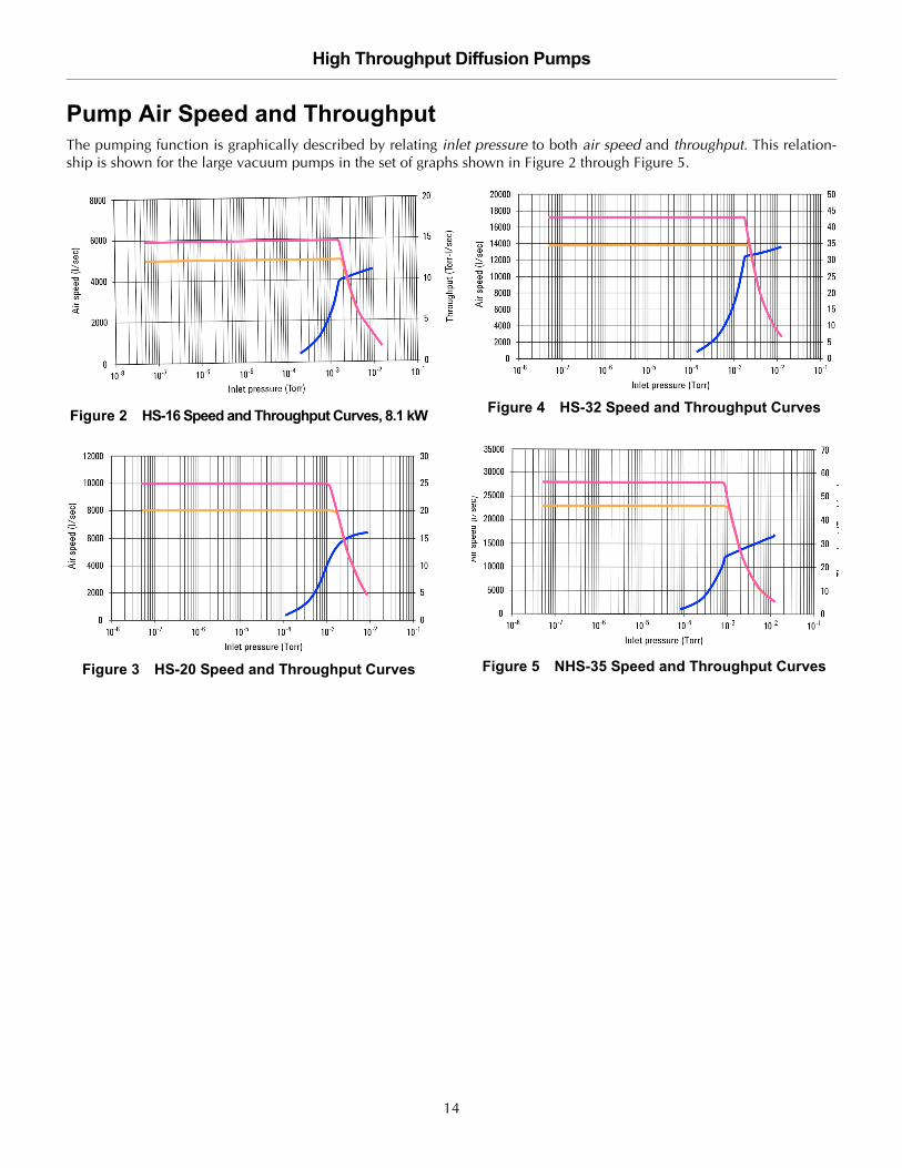
Pump Air Speed and ThroughputThe pumping function is graphically described by relating inlet pressure to both air speed and throughput. This relation-ship is shown for the large vacuum pumps in the set of graphs shown in Figure 2 through Figure 5.
Figure 2 HS-16 Speed and Throughput Curves, 8.1 kW
Figure 3 HS-20 Speed and Throughput Curves
Figure 4 HS-32 Speed and Throughput Curves
Figure 5 NHS-35 Speed and Throughput Curves
14

High Throughput Diffusion Pumps
DR
AF
T 7
/18
/14
Physical Specifications
Figure 6 HS-16 Outline with ASA Flanges
Table 5: HS-16: Dimensions and Weights
Units HS-16
Height, minimum including clearance for heater access
in (mm) 51 (1295.4)
Weight lbs (kg) 500 (227)
Connections:Body and ForelineQuick Cool coils
inin
1/4 FPT1/4 FPT
23.50 O.D.
16x1.12 holes
Electrical
7.50
4x75 holes
45°
1/4 F.P.T.Water Connections (Typ.)
3/2 F.P.T.Cold Cap Connections
NW-25 Gauge Port
1/4 F.P.T.Water Connections (Typ.)
Sight Glass with Fill and Drain
1/4 F.P.T.Quick Cool Coils (optional)
Electrical
24.00(610)
43.00(1092)
Foreline Cooling Coil
24.00(610)
Table 6 HS-16 Flange Dimensions
ASA ISO
Units Inlet Foreline Inlet, 500 K Foreline, 100 K
OD in (mm) 23.50 (596.9) 7.50 (190.5) 21.65 (549.9) 5.12 (130.1)
ID in (mm) 18.00 (457.2) 3.58 (90.9) 18.00 (457.2) 3.58 (90.9)
Thickness in (mm) 1.00 (25.4) 0.50 (12.7) 0.67 (17.0) 0.47 (11.9)
Bolt Circle in (mm) 21.25 (539.8) 6.00 (152.4)
No. of Holes 16 4
Size of Holes in (mm) 1.13 (28.7) 0.75 (19.1)
Orientation Holes straddle center line of foreline
Gasket Groove IDWidthDepth
in (mm)in (mm)in (mm)
18.69 (474.7)0.37 (9.4)0.18 (4.6)
4.31 (109.5)0.30 (7.6)0.14 (3.6)
Requires NW-500 Centering Ring (not included with pump)
Requires NW-100 Centering Ring (not included with pump)
15

High Throughput Diffusion Pumps D
RA
FT
7/1
8/1
4
Figure 7 HS-20 Outline with ASA Flanges
Table 7 HS-20: Dimensions and Weights
Units HS-20
Height, minimum including clearance for heater access
in (mm) 56 (1422)
Weight lbs (kg) 600 (272.2)
Connections:Body and ForelineQuick Cool coils
inin
1/4 FPT3/8 FPT
Table 8 HS-20 Flange Dimensions
ASA ISO
Units Inlet Foreline Inlet, 630 K Foreline, 160 K
OD in (mm) 27.50 (698.5) 9.00 (228.6) 27.17 (690.1) 7.09 (180.1)
ID in (mm) 21.25 (539.8) 5.06 (128.5) 21.25 (539.8) 5.06 (128.5)
Thickness in (mm) 1.12 (28.5) 0.75 (19.1) 0.78 (19.8) 0.47 (11.9)
Bolt Circle in (mm) 25.00 (635.0) 7.50 (190.5)
No. of Holes 20 8
Size of Holes in (mm) 1.25 (31.8) 0.75 (19.1)
Orientation Holes straddle center line of foreline
Gasket Groove IDWidthDepth
in (mm)in (mm)in (mm)
21.63 (549.4)0.48 (12.2)0.25 (6.6)
5.31 (134.9) 0.38 (9.7)0.09 (2.3)
Requires NW-630Centering Ring (not included with pump)
Requires NW-160Centering Ring (not included with pump)
16

High Throughput Diffusion Pumps
DR
AF
T 7
/18
/14
Figure 8 HS-32 Outline with ASA Flanges
Table 9 HS-32: Dimensions and Weights
Units HS-32
Height, minimum including clearance for heater access
in (mm) 74 (1879.6)
Weight lbs (kg) 1500 (680.4)
Connections:Body and ForelineQuick Cool coils
inin
3/8 FPT3/8 FPT
Table 10 HS-32 Flange Dimensions
ASA ISO
Units Inlet Foreline Inlet, 800 F Forline, 200 K
OD in (mm) 38.12 (968.3) 11.00 (279.4) 36.22 (920.0) 9.45 (240.0)
ID in (mm) 32.06 (814.3) 6.73 (170.9) 32.06 (814.3) 6.73 (170.9)
Thickness in (mm) 1.12 (28.5) 0.75 (19.1) 1.12 (28.5) 0.47 (11.9)
Bolt Circle in (mm) 36.25 (920.8) 9.50 (241.3) 35.04 (890.0)
No. of Holes 16 8 24
Size of Holes in (mm) 0.87 (22.1) 0.88 (22.4) 0.55 (14.0)
Orientation Holes straddle center line of foreline
Gasket Groove IDWidthDepth
in (mm)in (mm)in (mm)
32.5 (825.5)0.56 (14.2) 0.25 (6.4)
7.44 (189.0)0.38 (9.7)0.18 (4.6)
32.75 (831.9)0.56 (14.2)0.25 (6.35)
Requires NW-200Centering Ring (not included with pump)
17

High Throughput Diffusion Pumps D
RA
FT
7/1
8/1
4
Figure 9 NHS-35 Outline with ASA Flanges
Table 11 NHS-35: Dimensions and Weights
Units NHS-35
Height, minimum including clearance for heater access
in (mm) 80 (2032)
Weight lbs (kg) 1500 (680.4)
Connections:Body and ForelineQuick Cool coils
inin
3/8 FPT3/8 FPT
Foreline Cooling Coil
Table 12 NHS-35 Flange Dimensions
ASA ISO
Units Inlet Foreline Inlet, 1000 F Foreline, 200 K
OD in (mm) 41.75 (1060.5) 11.00 (279.4) 44.09 (1119.9) 9.45 (240.0)
ID in (mm) 35.00 (889.0) 7.72 (196.1) 35.00 (889.0) 7.72 (196.1)
Thickness in (mm) 1.12 (28.5) 0.75 (19.1) 1.12 (28.5) 0.47 (12.0)
Bolt Circle in (mm) 38.50 (977.9) 9.50 (241.3) 42.90 (1089.7)
No. of Holes 28 8 32
Size of Holes in (mm) 0.87 (22.1) 0.81 (20.6) 0.55 (14.0)
Orientation Holes straddles center line of foreline
Gasket Groove IDWidthDepth
in (mm)in (mm)in (mm)
35.37 (898.4)0.56 (14.2)0.25 (6.4)
8.20 (208.3)0.17 (4.3)0.09 (2.3)
40.75 (1035.1)0.56 (14.2)0.25 (6.4)
Requires NW-200Centering Ring (not included with pump)
18

High Throughput Diffusion Pumps
DR
AF
T 7
/18
/14
Unpacking
Agilent large diffusion pumps are shipped in sturdy con-tainers that permit prolonged storage in suitably protectedareas without special precautions, however, care must betaken when moving the crated pump with a fork lift toavoid excessive shock.
Carefully remove the outer shipping container. Visuallyinspect the pump for damage that may have occurredduring shipping and notify the carrier immediately if dam-age is suspected. If damage is noticed, save the crate andthe internal packing for inspection.
Setup
Assembly1. Remove flange covers, blank plugs and protective
plugs from water connections. Do not to scratch or otherwise damage the sealing surface (the O-ring groove on top of the inlet flange).
2. Check the internal jet assembly. It should be concentric and firmly seated on the bottom of the pump. Use a flashlight to verify that the ejector nozzle is opposite the foreline (the pump outlet connection). The jet assembly should not rotate; it is held by an indexing pin at the bottom of the assembly.
3. If the expected vacuum level is below 107 Torr, clean the pump using the procedure outlined in the next section. Otherwise make sure that there are no foreign materials inside the pump, and proceed with attaching the pump to the system as instructed in “System and Utility Connections” on page 21.
WARNINGS ❑ Before lifting a pump, check the weight of the equipment in Table 4 on page 12.
❑ Use power-assisted equipment, and trained moving and installation personnel to avoid dropping, slipping, and overturning the pump and severely injuring personnel.
❑ Do not stand under equipment being moved.
19

High Throughput Diffusion Pumps D
RA
FT
7/1
8/1
4
Cleaning a New Pump
Cleaning SafetyCleaning a diffusion pump involves the use of acetoneand alcohol, both of which are toxic and explosive. Takecareful note of the following information and warningsbefore starting a cleaning process.
When heated, sprayed or exposed to high temperatureequipment, these solvents become flammable and explo-sive, causing serious injury or death.
When heated or sprayed, acetone or alcohol alsobecomes 4 to 5 times heavier than air and flows down,settling in tanks, pits, and low areas, displacing air, andthus, can kill by asphyxiation.
Acetone, alcohol, and other solvents are irritants, narcot-ics, depressants, and carcinogenic. Their inhalation andingestion may produce serious effects. Prolonged or con-tinued contact with the skin will result in absorptionthrough the skin and moderate toxicity.
Disassembly for Initial CleaningThis procedure involves the cleaning of the following elements:
❑ Jet assembly
❑ Drain plugs
❑ Sight glass
❑ Pump interior
To disassemble the pump:
1. Remove the cold cap as described in “Cold Cap” on page 43.
2. Disassemble the internal jet system from the body of the pump in accordance with the appropriate procedure within “Jet Assemblies” on page 44.
3. Remove fill and drain plugs and the sight glass with its O-ring and graphite gasket.
Set the O-ring aside as it must not be cleaned with astrong solvent. Alcohol, acetone, and other solventsdegrade O-ring materials reducing their ability to hold avacuum. If it is necessary to clean any O-rings, wipe withlint-free, clean cloth, wash in detergent and water, or usea small amount of pump fluid.
4. Thoroughly clean all components of the jet assembly and pump casing interior (but not O-rings) with acetone followed by an alcohol rinse.
5. Remove all traces of cleaning fluid by carefully drying all components with clean, dry, oil-free compressed air.
Reassembly After Initial CleaningTo reassemble the pump:
1. Perform disassembly steps 1 to 3 in reverse order, then continue with the following steps on a cleaned, reassembled pump.
2. Clean the interface and inlet flanges and O-ring grooves thoroughly with acetone or alcohol, using clean, lint free rags.
3. Remove all traces of acetone and alcohol by carefully drying all components, particularly the O-ring grooves, with clean, dry, oil-free compressed air.
4. Re-install the O-ring gasket.
NOTE A new pump requires cleaning only if the desired vacuum is below 1x10⁷ Torr.
WARNINGS ❑ Do not use near a high temperature source.
❑ Always use in a large, well-ventilated room and ventilate the working area with a blower.
❑ Wear eyeshields, gloves, and other protective clothing. The use of a self-contained breathing apparatus may also be necessary.
CAUTION Do not use any solvents on O-rings.
20
High Throughput Diffusion Pumps
DR
AF
T 7
/18
/14
System and Utility Connections
Vacuum ConnectionsThe pump body must be installed vertical and plumb.Check that the mating flange on the system is horizontal±1o. If this condition is not met, correct the system mountbefore installing the pump.
To make the vacuum system connection:
1. Wipe the O-ring seals with a clean cloth lightly moistened with diffusion pump fluid. Do not use solvents.
2. Install the O-ring in its groove. Be careful not to damage the sealing surface with cuts, nicks, or scratches.
3. Raise the pump using a lifting apparatus with sufficient capacity. Pump weights are given in Table 4 on page 12.
4. Align the bolt holes of the flanges and assemble the bolts.
5. Tighten the bolts evenly and compress the O-ring seal until light contact is achieved between the metal flanges.
6. Make a tightness check of the fill and drain plugs and the sight glass assembly. Refer to the appropriate outline drawings, Figure 6 on page 15 through Figure 9 on page 18. Apply light to medium torque, just enough to visually compress the gaskets.
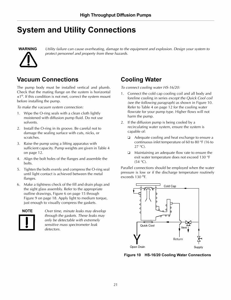
Cooling WaterTo connect cooling water HS-16/20:
1. Connect the cold cap cooling coil and all body and foreline cooling in series except the Quick Cool coil (see the following paragraph) as shown in Figure 10. Refer to Table 4 on page 12 for the cooling water flowrate for your pump type. Higher flows will not harm the pump.
2. If the diffusion pump is being cooled by a recirculating water system, ensure the system is capable of:
❑ Adequate cooling and heat exchange to ensure a continuous inlet temperature of 60 to 80 °F (16 to 27 °C).
❑ Maintaining an adequate flow rate to ensure the exit water temperature does not exceed 130 °F (54 °C).
Parallel connections should be employed when the waterpressure is low or if the discharge temperature routinelyexceeds 130 oF.
Figure 10 HS-16/20 Cooling Water Connections
WARNING Utility failure can cause overheating, damage to the equipment and explosion. Design your system to protect personnel and property from these hazards.
NOTE Over time, minute leaks may develop through the gaskets. These leaks may only be detectable with extremely sensitive mass spectrometer leak detectors.
Return
21

High Throughput Diffusion Pumps D
RA
FT
7/1
8/1
4
To connect cooling water HS-32/NHS-35:
1. Connect all body and foreline cooling in series except the Quick Cool coil. Connect the Cold Cap cooling coil separately (Figure 11). Refer to Table 4 on page 12 for the cooling water flow rate. Higher flows will not harm the pump.
2. If the diffusion pump is being cooled by a recirculating water system, ensure the system is capable of:
❑ Adequate cooling and heat exchange to ensure a continuous inlet temperature of 60 to 80 °F (16 to 27 °C).
❑ Maintaining an adequate flow rate to ensure the exit water temperature does not exceed 130 °F (54 °C).
Parallel connections should be employed when the waterpressure is low or if the discharge temperature from thepump body routinely exceeds 130 oF (54 °C).
Figure 11 HS-32/NHS-35 Cooling Water Connections
Quick Cool Coil Connection
The Quick Cool coil at the boiler plate must be con-nected to an open drain and the feed line must be con-trolled by a separate water 3-way valve: open, closed,and vented to the atmosphere. The drain must be belowthe boiler level so that it is drained completely when theQuick Cool coil water supply is shut off and the pump isoperating.
Return
Return Supplies
Pump
22

High Throughput Diffusion Pumps
DR
AF
T 7
/18
/14
Obtaining High Vacuum on the NHS-35
When operating at low pressures (below 1x10⁶ Torr), theultimate pressure can be lowered by bypassing the por-tion of the cooling coils located at the bend of the forelineas shown in Figure 9 on page 18. This procedure raisesthe temperature of the foreline and provides additionaldegassing of the fluid returning to the boiler, thus makinglower pressures possible.
NOTE This configuration decreases the maximum throughput capacity of the pump. Use this cooling configuration only if the pump is not meant to operate near the high pressure end of its operating range.
23

High Throughput Diffusion Pumps D
RA
FT
7/1
8/1
4
Electrical ConnectionsTerminal connections for each pump are different depending on the source voltage available, the principle differencebeing a Y or connection of the heaters. Table 13 provides the figure number and page of the wiring diagrams in thismanual. The specific wiring diagrams for each pump shows both Y and connections and the source voltages for eachconnection.
WARNING Improper operation, severe heater damage, and danger to personnel can result from an improperly wired diffusion pump system.
WARNING High voltages (up to 480 V) can kill. Always break the primary circuit to the pump before starting work on the heater or its wiring.
Table 13 Wiring Diagram Locations
Source Voltage HS-16 Wiring HS-20 Wiring HS-32 Wiring NHS-35 Wiring
200 Delta Figure 14 on page 28
208 Delta Figure 12 on page 26 Figure 14 on page 28
220 Delta Figure 14 on page 28 Figure 16 on page 30 Figure 19 on page 33
240 Delta Figure 12 on page 26 Figure 14 on page 28 Figure 16 on page 30 Figure 19 on page 33
265 Delta Figure 14 on page 28
380 Delta Figure 12 on page 26 Figure 14 on page 28 Figure 19 on page 33
380 Wye Figure 15 on page 29
400 Delta Figure 12 on page 26 Figure 14 on page 28 Figure 16 on page 30
415 Wye Figure 13 on page 27 Figure 15 on page 29 Figure 17 on page 31 Figure 20 on page 34
430 Delta Figure 12 on page 26 Figure 14 on page 28
440 Delta Figure 12 on page 26 Figure 14 on page 28 Figure 16 on page 30
460 Delta Figure 12 on page 26 Figure 14 on page 28 Figure 19 on page 33
480 Delta Figure 12 on page 26 Figure 14 on page 28 Figure 18 on page 32 Figure 21 on page 35
575 Delta Figure 12 on page 26 Figure 14 on page 28
CAUTION Do not operate the pump at more than 5% over its rated voltage.
All electrical connections must be made by qualified personnel in accordance with all applicable laws and industrial codes.
For overcurrent protection, the pump must be installed with appropriate branch circuit protection.
To guarantee electrical safety, ensure the diffusion pump is bonded to the earth ground system.
24

High Throughput Diffusion Pumps
DR
AF
T 7
/18
/14
To wire the pump:
1. Check the heater for correct supply voltage and find the appropriate wiring diagram. The correct voltage is shown.
2. Check load balance by measuring the resistance of each branch. The heater resistances are given on their respective wiring diagrams.
3. Make the connections to the terminals in the electrical main junction box at the foreline shown in the appropriate outline drawing. Use flexible conduit to make it easier to remove the pump for service.
4. Connect the earth ground wire directly to the aluminum set screw ground lug.
5. Connect the input wires to the terminal block positions L1, L2 and L3(& N). For added safety, to prevent the wires from being disconnected, secure these wires together with the earth ground wire inside the junction box with a tie-wrap, similar to what has been done with the heater wires.
6. Wire the thermal switches to a control mechanism to ensure that power to the pump is shut off if one of the switches opens. The thermal switch wires can be found in the electrical box.
7. Complete the wiring of the pump and double-check that the proper terminal arrangement has been used for the source voltage at the site.
Overheating: Detection by Thermal SwitchesAn overheat condition is detected by two normally closedthermal cutout switches, one of which monitors the boilertemperature while the other monitors the water tempera-ture. These switches are set at the factory and do notrequire adjustment. The cutout temperatures for the waterand boiler switches are given in Table 14.
Wire the pump such that if the contacts open on eitherthe boiler or the water switch, power to the pump shutsoff. If this happens during operation, check for one of thefailure conditions listed below. When the problem hasbeen corrected and the temperature lowered, the thermalswitch automatically resets.
A rise in pump temperature can be caused by:
❑ Failure of cooling water flow
❑ High inlet pressure
❑ Low fluid level in the boiler
If you determine that the pump has not overheated andthat the thermal switch has failed or drifted out of calibra-tion, replace the switch with the device listed for yourpump type in the appropriate Replacement Parts table,page 53 through page 56.
Table 14 Thermal Cutout Temperatures
Units HS-16 HS-20 HS-32 NHS-35
Water Switch °F 185 185 220 200
Boiler Switch °F 390 390 550 600
CAUTION Thermal switches set to measure the temperature in the diffusion pump fluid are not designed to protect against overheating or backstreamed mechanical pump fluids.
25
High Throughput Diffusion Pumps D
RA
FT
7/1
8/1
4
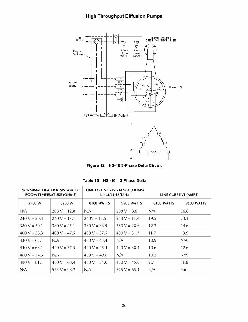
Figure 12 HS-16 3-Phase Delta Circuit
Table 15 HS -16 3 Phase Delta
NORMINAL HEATER RESISTANCE @ ROOM TEMPERATURE (OHMS)
LINE TO LINE RESISTANCE (OHMS) L1-L2/L2-L3/L3-L1 LINE CURRENT (AMPS)
2700 W 3200 W 8100 WATTS 9600 WATTS 8100 WATTS 9600 WATTS
N/A 208 V = 12.8 N/A 208 V = 8.6 N/A 26.6
240 V = 20.3 240 V = 17.1 240V = 13.5 240 V = 11.4 19.5 23.1
380 V = 50.1 380 V = 45.1 380 V = 33.9 380 V = 28.6 12.3 14.6
400 V = 56.3 400 V = 47.5 400 V = 37.5 400 V = 31.7 11.7 13.9
430 V = 65.1 N/A 430 V = 43.4 N/A 10.9 N/A
440 V = 68.1 440 V = 57.5 440 V = 45.4 440 V = 38.3 10.6 12.6
460 V = 74.5 N/A 460 V = 49.6 N/A 10.2 N/A
480 V = 81.1 480 V = 68.4 480 V = 54.0 480 V = 45.6 9.7 11.6
N/A 575 V = 98.2 N/A 575 V = 65.4 N/A 9.6
26

High Throughput Diffusion Pumps
DR
AF
T 7
/18
/14
Figure 13 HS-16 3-Phase WYE Circuit
Table 16 HS -16 3 Phase WYE
NORMINAL HEATER RESISTANCE @ ROOM TEMPERATURE (OHMS)
LINE TO LINE RESISTANCE (OHMS) L1-L2/L2-L3/L3-L1 LINE CURRENT (AMPS)
2700 W 3200 W 8100 WATTS 9600 WATTS 8100 WATTS 9600 WATTS
240 V = 20.3 240 V = 17.1 415 V = 40.4 415 V = 34.1 11.3 13.4
27

High Throughput Diffusion Pumps D
RA
FT
7/1
8/1
4
Figure 14 HS-20 3-Phase Delta Parallel Circuit
Table 17 HS -20 3-Phase Delta Parallel
NORMINAL HEATER RESISTANCE @ ROOM TEMPERATURE (OHMS) LINE TO LINE RESISTANCE (OHMS) L1-L2/L2-L3/L3-L1 LINE CURRENT (AMPS)
2000 W 12000 Watts 12000 Watts
200 V = 19 200 V = 6.3 34.6
208 V = 20.5 208 V = 6.8 33.3
220 V = 22.9 220 V = 8.1 31.5
240 V = 27.3 240 V = 9.1 28.9
265 V = 33.3 265 V = 11.1 26.1
380 V = 68.5 380 V = 22.8 18.2
400 V = 75.8 400 V = 25.3 17.3
420 V = 83.6 420 V = 27.8 16.5
430 V = 87.6 430 V = 29.2 16.1
440 V = 91.8 440 V = 30.6 15.8
460 V = 100.3 460 V = 33.4 15.1
480 V = 109.2 480 V = 36.4 14.4
575 V = 156.7 575 V = 52.2 12.1
28

High Throughput Diffusion Pumps
DR
AF
T 7
/18
/14
Figure 15 HS-20 3-Phase WYE Parallel Circuit
Table 18 HS -20 3-Phase WYE Parallel
NORMINAL HEATER RESISTANCE @ ROOM TEMPERATURE (OHMS) LINE TO LINE RESISTANCE (OHMS) L1-L2/L2-L3/L3-L1 LINE CURRENT (AMPS)
2000 W 12000 Watts 12000 Watts
220 V = 22.9 380 V = 22.8 18.2
240 V = 27.3 415 v = 27.2 16.7
29
High Throughput Diffusion Pumps D
RA
FT
7/1
8/1
4
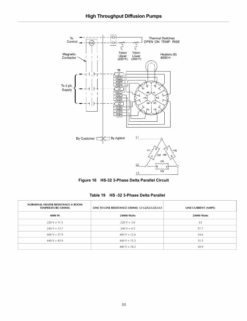
Figure 16 HS-32 3-Phase Delta Parallel Circuit
Table 19 HS -32 3-Phase Delta Parallel
NORMINAL HEATER RESISTANCE @ ROOM TEMPERATURE (OHMS) LINE TO LINE RESISTANCE (OHMS) L1-L2/L2-L3/L3-L1 LINE CURRENT (AMPS)
4000 W 24000 Watts 24000 Watts
220 V = 11.5 220 V = 3.8 63
240 V = 13.7 240 V = 4.5 57.7
400 V = 37.9 400 V = 12.6 34.6
440 V = 45.9 440 V = 15.3 31.5
480 V = 18.2 28.9
30

High Throughput Diffusion Pumps
DR
AF
T 7
/18
/14
Figure 17 HS-32 3-Phase WYE Parallel Circuit
Table 20 HS -32 3-Phase WYE Parallel
NORMINAL HEATER RESISTANCE @ ROOM TEMPERATURE (OHMS) LINE TO LINE RESISTANCE (OHMS) L1-L2/L2-L3/L3-L1 LINE CURRENT (AMPS)
4000 W 24000 Watts 24000 Watts
240 V = 13.7 415 V = 13.6 33.4
31

High Throughput Diffusion Pumps D
RA
FT
7/1
8/1
4
Figure 18 HS-32 3-Phase Delta Series Circuit
Table 21 HS -32 3-Phase Delta Series
NORMINAL HEATER RESISTANCE @ ROOM TEMPERATURE (OHMS) LINE TO LINE RESISTANCE (OHMS) L1-L2/L2-L3/L3-L1 LINE CURRENT (AMPS)
4000 W 24000 Watts 24000 Watts
240 V = 13.7 480 V = 18.2 28.9
32

High Throughput Diffusion Pumps
DR
AF
T 7
/18
/14
Figure 19 NHS-35 3-Phase Delta Parallel Circuit
Table 22 NHS-35 3-Phase Delta Parallel
NORMINAL HEATER RESISTANCE @ ROOM TEMPERATURE (OHMS) LINE TO LINE RESISTANCE (OHMS) L1-L2/L2-L3/L3-L1 LINE CURRENT (AMPS)
4000 W 24000 Watts 24000 Watts
220 V = 11.5 220 V = 3.8 63
240 V = 13.7 240 V = 4.5 57.7
380 V = 34.2 380 V = 11.4 36.5
460 V = 37.9 460 V = 16.8 30.1
480 V = 18.2 28.9
33

High Throughput Diffusion Pumps D
RA
FT
7/1
8/1
4
Figure 20 NHS-35 3-Phase WYE Parallel Circuit
Table 23 NHS-35 3-Phase WYE Parallel
NORMINAL HEATER RESISTANCE @ ROOM TEMPERATURE (OHMS) LINE TO LINE RESISTANCE (OHMS) L1-L2/L2-L3/L3-L1 LINE CURRENT (AMPS)
4000 W 24000 Watts 24000 Watts
240 V = 13.7 415 V = 13.6 33.4
34

High Throughput Diffusion Pumps
DR
AF
T 7
/18
/14
Figure 21 NHS-35 3-Phase Delta Series Circuit
Table 24 NHS-35 3-Phase Delta Series
NORMINAL HEATER RESISTANCE @ ROOM TEMPERATURE (OHMS) LINE TO LINE RESISTANCE (OHMS) L1-L2/L2-L3/L3-L1 LINE CURRENT (AMPS)
4000 W 24000 Watts 24000 Watts
240 V = 13.7 480 V = 18.2 28.9
35

High Throughput Diffusion Pumps D
RA
FT
7/1
8/1
4
Initial Vacuum Test
Before charging the pump with fluid, carry out this initialvacuum test to establish the tightness of the system and itsvacuum connections.
Pumps and their components are designed for vacuumservice; they are not designed to be pressurized whichcould cause them to burst possibly expelling shrapnel atlethal velocities. Serious accidents have been caused byintentional pressurization of vacuum systems and theircomponents.
To perform the initial vacuum test:
1. Confirm the vacuum ultimate pressure characteristics of the fore pump. This should closely approximate the value quoted in the manufacturer's data, if the mechanical pump is correctly installed, adjusted, and filled with clean fluid.
2. Measure pressure with a continuously indicating total pressure gauge, such as a capacitance manometer, or thermocouple gauge.
3. Connect the outlet (or foreline) of the diffusion pump to the inlet of the fore pump using vacuum-tight connections.
4. The procedure varies for valved and unvalved systems.
❑ For valved system: Close the roughing valve and main isolation valve ahead of the diffusion pump.
❑ For unvalved systems: Include the entire work chamber volume in the test.
5. Evacuate the system using only the fore pump. Let the pump reach an ultimate pressure in the system. This reading should approximate the value obtained in step 2 above (usually 10 to 50 microns, 0.013 mbar to 0.067 mbar).
6. If the pump does not reach this level, examine the system for leakage following standard procedures for leak testing. These procedures depend on the type of vacuum gauges and leak detection equipment available.
WARNINGS ❑ Never pressurize any part of a vacuum system for test or any other purpose.
❑ Always provide pressure relief when designing diffusion pumps into systems and ensure that pressure relief motion is limited to safe envelopes.
NOTE Consult with your Agilent representative for information on Agilent’s extensive line of helium leak detectors.
36

High Throughput Diffusion Pumps
DR
AF
T 7
/18
/14
Adding or Changing Pump Fluid The recommended fluid charge for each pump is given inTable 4 on page 12.
Fluids must be stored in clean, tightly closed containersand should be clearly identified in accordance with theirtype. Do not mix pumping fluids of different types andorigins. Generally, it is not a good idea to mix used andnew fluid for a pump charge.
Information on Fluid and DP PerformanceThe choice of fluid depends on the application. The mostcommon type of fluid used in the market is a siliconebased fluid, and all vacuum performance data in thismanual was generated using a silicone based fluid calledDC704. There are many fluids on the market that areequivalent to the DC704. The pump will operate withother types of oil, but the performance may be different.Since there are so many options, it is not possible to sum-marize and recommend them all.
WARNINGS The risk of explosion on large vacuum diffusion pumps is increased by these factors:
❑ Use of a hydrocarbon fluid as the pumping fluid. Hydrocarbon fluid is more prone to explosion than synthetic silicone-based fluid. If a hydrocarbon fluid is being used, check the entire system under vacuum before operating the pump.
❑ Low fluid levels in the pump which can lead to overheating. Low fluid levels develop because the charge gradually depletes during use. The pump, however, continues to operate normally and when the charge drops to 60% of initial level, the boiler temperature may begin to rise. If this takes place, the thermal switches open the heater circuits. For details, refer to “Overheating: Detection by Thermal Switches” on page 25.
❑ Overheated pump fluid that decomposes and becomes toxic. The toxic fluid residue may be on the dipstick used to check fluid level, so care must always be taken to assure personnel do not contact or ingest the fluid.
❑ Admission of atmospheric air during pump operation. Leakage of air into the system allows oxygen into the fluid vapor and increases the risk of explosion. If holding a vacuum is difficult, perform a leak test. Do not use the pump until the leak source is located and repaired.
CAUTION The use of Santovac® 5 Diffusion Pump Fluid is not recommended in these pumps, nor is the use of any hydrocarbon fluid.
37

High Throughput Diffusion Pumps D
RA
FT
7/1
8/1
4
To add or change pump fluid:
1. Locate the fill and drain fittings in the appropriate outline drawing. Refer to Figure 6 on page 15 through Figure 9 on page 18. The fittings have special Viton® elastomer sealed plugs.
2. Assure that the power to the heaters is off.
3. Remove the drain plug and drain fluid into a suitable sized container.
4. Remove the plug from the filling port of the pump and pour the fluid in up to the FULL COLD level on the sight glass as shown in Figure 22. The fluid can also be poured in from the pump inlet or foreline.
Figure 22 Sight Glass Assembly
5. Replace the fill plug with a new Viton gasket. Lubricate the O-ring with pump fluid, put the O-ring in place, and reassemble the system.
6. Tighten the fill plug using maximum torque of 75 inches-pounds.
Once the pump is running, check that the fluid level is atthe FULL HOT level in the sight glass.
CAUTION Wait until the pump has cooled then vent it to the atmosphere.
NOTE Dispose of fluids in accordance with all appropriate regulations.
38

High Throughput Diffusion Pumps
DR
AF
T 7
/18
/14
Operation
During initial installation, the newly installed pump fluidmay be subjected to degassing. This may result in forelinepressure fluctuations that are considered normal.
WARNINGS The following conditions increase the risk of explosion:
❑ Air leaks into the system
❑ Roughing through a hot diffusion pump, which can cause hot hydrocarbon fluids to ignite or explode when exposed to air
❑ Air release or the admission of air to a pump with a hot boiler (permitting a strong oxidizer to contact the hot pump fluid)
❑ Pressure above 1 milliTorr (1.3X10³ mbar)
❑ Insufficient (or low level of) pump fluid
❑ Operating a pump without circulating cool water to the main body cooling coils
❑ Operating pump with water trapped in Quick Cool coil
❑ Foreign matter in the pumping fluid, which changes its viscosity and obstructs flow passages
CAUTIONS ❑ Do not turn on the heater without fluid in the pump. This may ruin the heaters and damage the pump.
❑ Do not air-release the pump while the boiler is hot. Most diffusion pump fluids break down under these conditions.
❑ Do not operate the pump heater unless cooling water is circulating. Doing so causes the pump and fluid to overheat.
❑ Do not operate without a foreline baffle. This can cause a greater than normal fluid loss. *The HS-32 does not have a foreline baffle.
39

High Throughput Diffusion Pumps D
RA
FT
7/1
8/1
4
Startup ProcedureTo start the pump:
1. Evacuate the diffusion pump using a mechanical roughing pump to below 0.5 Torr (0.67 mbar). The diffusion pump will not function unless the discharge pressure is less than the tolerable forepressure.
2. Turn on the cooling water supply to the pump body and check that adequate flow is provided by examining the amount of water discharged at the visual drain points.
3. Switch on the power to the diffusion pump heater.
4. Check inlet and forepressure performance by means of the system instrumentation.
Humid EnvironmentsDue to their inherent design, diffusion pump heatersabsorb moisture. This results in a decrease in heater insu-lation resistance (higher leakage current). Under normalconditions, the decrease in insulation resistance is amomentary condition that occurs on startup. The amountof moisture adsorbed is depends on the temperature,humidity, and the length of time the heaters have beenexposed to this environment without power beingapplied. If diffusion pumps are started in high humidityenvironments, the heaters may be damaged on startup atfull power. To overcome the effect of moisture absorbedin the heaters, start pumps at a low line voltage, e.g., 50%of line voltage, for a period or time to slowly expel anymoisture.
Shutdown Procedure
To shut down the pump:
1. Close the inlet valve on the system, if equipped.
2. Turn off the power to the heaters.
3. For pumps equipped with the optional Quick Cool Coil, admit water into the coil.
4. Continue to flow cooling water through the pump (and Quick Cool Coil, if equipped) for at least the time period listed under “Cooldown Time Without Quick Cool With Quick Cool” in Table 4 on page 13.
5. Once the pump is cooled, shut off the mechanical backing pump.
6. Air release the pump.
7. Continue cooling water flow until the pump is at room temperature, then shut off the water supply.
CAUTION To prevent harmful collection of condensate on the boiler plate, heater, and heater terminals, do not operate the Quick Cool coil when the pump is cold or out of service.
WARNING 1. Releasing or admitting air to a pump with a hot boiler, especially when it is under vacuum, permits a strong oxidizer to contact the hot pump fluid and greatly increases the risk of an explosion.
2. Boiler temperatures reach 530° F (275 °C) which can cause serious burns. Always check that surfaces have cooled to near room tempera-ture before touching them.
40
High Throughput Diffusion Pumps
DR
AF
T 7
/18
/14
Maintenance
Perform these periodic checks to assure trouble-free operation. This maintenance prevents costly down-time and cleaningprocedures. Maintain a day-to-day log of pump and system performance to identify marked variations that require correc-tive action.
Periodic InspectionsThe maximum interval between inspection of the pump isestablished on the basis of experience.
To perform general maintenance, do the following:
1. Check the condition and level of fluid when the pump is cold. Withdraw a sample through the drain and visually check the level of fluid through the sight glass. Slight discoloration of the fluid does not affect pump performance. Use new O-ring gaskets when replacing fill and drain plugs.
Loss of the fluid can be caused by:
❑ Admittance of excessive air or other gas to a hot pump
❑ Inadequate water cooling
❑ Continuous operation in the overload range as given in Table 4 on page 12
❑ Failure to reinsert the foreline baffle in the pump assembly
2. When the pump is cold, check that the heaters are bolted snugly to the boiler plate and that all heater terminal connections are fastened tightly inside the junction box.
3. Check the total heater power input and balance of the load.
4. Ensure that cooling water flow is unobstructed and that the flow rate does not fall not below quantities specified in Table 4 on page 12.
WARNINGS ❑ High voltages (up to 480 V) can kill. Always break the primary circuit to the power supply before starting work on the heater or its wiring.
❑ Avoid the possibility of serious burns by making sure that the pump is at room temperature before attempting service.
❑ Always wear appropriate gloves and clothing and use a self-contained breathing apparatus. Poisonous or corrosive compounds may be present when opening the fill or drain.
❑ Explosion risk is high if the fill or drain is opened when the pump is running or when it is hot.
NOTE The HS-32 does not have a foreline baffle.
41
High Throughput Diffusion Pumps D
RA
FT
7/1
8/1
4
Cleaning
Cleaning SafetyCleaning a diffusion pump involves the use of acetoneand alcohol, both of which are toxic and explosive. Takecareful note of the following warnings before starting acleaning process.
When heated, sprayed or exposed to high temperatureequipment, these solvents become flammable and explo-sive, causing serious injury or death.
When heated or sprayed, acetone or alcohol alsobecomes 4 to 5 times heavier than air and will flowdown, settling in tanks, pits, and low areas, thus displac-ing air which can kill by asphyxiation.
Acetone, alcohol, and other solvents are irritants, narcot-ics, depressants, and carcinogenic. Their inhalation andingestion may produce serious effects. Prolonged or con-tinued contact with the skin will result in absorptionthrough the skin and moderate toxicity.
Complete cleaning of the pump may be required due togradual deterioration of pump fluids. Removal of thepump from the system is then necessary.
To clean an installed pump:
1. Disconnect all water cooling lines and break the primary circuit supplying power to the pump heaters.
2. Unbolt the inlet and foreline connections and remove the pump from the system.
3. Drain the pump of all fluid.
4. Remove the cold cap as described in “Cold Cap” on page 43.
5. Remove the jet assembly as described for the specific pump model in “Jet Assemblies” on page 44.
6. Thoroughly clean the pump body interior using acetone followed by an isopropyl alcohol rinse and then dry the pump with clean, dry, oil-free compressed air.
7. Thoroughly clean the jet assembly using acetone. Wipe all surfaces with isopropyl alcohol, and dry with clean, dry, oil-free compressed air.
8. Reinstall the jet and cold cap in the pump body. Be sure that the ejector is properly aligned with the foreline.
9. Check the condition of the O-rings. Replace O-rings that show any sign of wear or compression.
10. Attach the pump in the system.
WARNINGS ❑ Do not use near a high temperature source. Ventilate the working area with a blower and use in a large, well-ventilated room. The use of a self-contained breathing apparatus may also be necessary.
❑ Always ensure that cleaning operations are carried out in large, well-ventilated rooms. Wear eyeshields, gloves, and protective clothing.
42

High Throughput Diffusion Pumps
DR
AF
T 7
/18
/14
Disassembly and Reassembly Procedures
Cold Cap To disassemble the cold cap, refer to Figure 23 and takethe following steps.
1. Remove the female coupling, nut, follower, and gasket located at the end of the cold cap water line on the outside of the pump.
2. Remove the cold cap securing screw which secures the cold cap to the jet assembly.
3. Lift out the cold cap.
To reassemble the cold cap:
1. Insert the end of the cold cap water line into the cold cap port opening at the side of the pump before setting the cold cap on top of the jet assembly. Be careful not to damage the sealing surfaces.
2. Replace the cold cap securing screw which secures the cold cap to the jet assembly. Do not overtighten the screw.
3. Replace the gasket, the follower, the nut, and the female coupling to the side of the pump.
Figure 23 Cold Cap Assembly
NOTE The halo baffle is disassembled in the same manner.
NOTE Supply water tubing must be connected to the cold cap coupling with FPT threads.
COLD CAP ASSEMBLY
43

High Throughput Diffusion Pumps D
RA
FT
7/1
8/1
4
Jet AssembliesThe jet assemblies of each of the pumps are discussedand shown in the following subsections. Procedures anddrawings are specific to each pump model.
HS-16 Jet Assembly
Figure 24 HS-16 Jet Assembly
To disassemble the jet assembly:
1. Remove the cold cap or halo baffle as described in “Cold Cap” on page 43.
2. Unscrew the top cap from its coupling and remove it.
3. Remove the top plug.
4. Remove the drip shield that sits loosely on the 2nd stage.
5. Lift and remove the entire 2nd stage.
6. Lift and individually remove the 3rd stage, the 4th stage, and the jet base.
7. Remove the two nuts securing the splash baffle, then lift and remove the splash baffle.
8. Remove the jam nut located at the center-bottom of the pump in order to remove the jet rod.
To assemble the jet assembly:
❑ Reverse the disassembly steps above.
NOTE When the jet assembly is installed in the pump body, be sure that the slot in the jet base is engaged in the locating pin of the boiler. Unless this is done, the pump will not function properly.
NOTE If the jet coupling loosens from the jet rod during disassembly, position it so that the top of the jet coupling is flush with the bottom orifice plug as can be seen in Figure 26.
44
High Throughput Diffusion Pumps
DR
AF
T 7
/18
/14
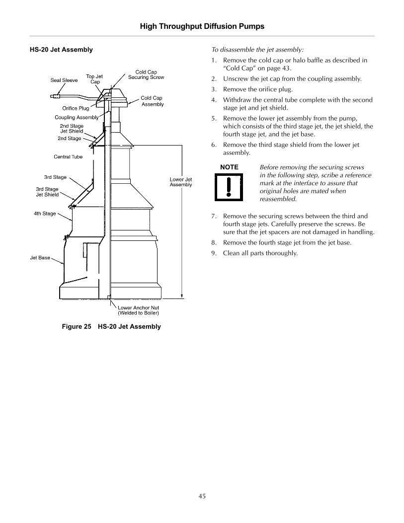
HS-20 Jet Assembly
Figure 25 HS-20 Jet Assembly
To disassemble the jet assembly:
1. Remove the cold cap or halo baffle as described in “Cold Cap” on page 43.
2. Unscrew the jet cap from the coupling assembly.
3. Remove the orifice plug.
4. Withdraw the central tube complete with the second stage jet and jet shield.
5. Remove the lower jet assembly from the pump, which consists of the third stage jet, the jet shield, the fourth stage jet, and the jet base.
6. Remove the third stage shield from the lower jet assembly.
7. Remove the securing screws between the third and fourth stage jets. Carefully preserve the screws. Be sure that the jet spacers are not damaged in handling.
8. Remove the fourth stage jet from the jet base.
9. Clean all parts thoroughly.
NOTE Before removing the securing screws in the following step, scribe a reference mark at the interface to assure that original holes are mated when reassembled.
45

High Throughput Diffusion Pumps D
RA
FT
7/1
8/1
4
To reassemble the jet assembly:
1. Replace the fourth stage jet on the jet base.
2. Replace and tighten the securing screws between the fourth stage and the jet base uniformly and in a cyclical pattern.
3. Replace the third stage jet on the fourth stage.
4. Replace and tighten the securing screws between the third stage and fourth stage uniformly and in a cyclical pattern.
5. Replace the third stage jet shield.
6. Install the lower jet assembly in the pump.
7. Check that the lower jet assembly is firmly seated on the pump with the ejector correctly positioned. For proper alignment, a pin is provided in the base of the pump; the large slot in the jet base must register on this pin.
8. Follow steps 1 through 5 in reverse order.
Figure 26 Jet Coupling Detail
NOTE Jet spacings are preset at the factory and controlled by the spacers secured to the respective stages.
NOTE If the jet coupling loosens from the jet rod during disassembly, position it so that the top of the jet coupling is flush with the bottom orifice plug (Figure 26).
Jam NutJet Rod
Jet Coupling
Cold Cap
Top Jet
Orifice Plug
Cold Cap
Detail A
Securing Screw
Assembly
Location of Jet Couplingprior to assembling Jet Cap.
46

High Throughput Diffusion Pumps
DR
AF
T 7
/18
/14
HS-32 Jet Assembly
Figure 27 HS-32 Jet Assembly
To disassemble the jet:
1. Unscrew and remove the hex nut holding the cold cap in place. Note its orientation prior to removal
2. Remove the cold cap (or halo baffle) as described in “Cold Cap” on page 43.
3. Remove the nut, washer, and the top jet cap from the center jet rod.
4. Using the now-exposed cross member and the appropriate lifting equipment, lift the entire jet assembly out of the pump body, leaving the jet rod in place.
5. Remove the second stage jet shield.
6. Remove the two nuts on the cross member and lift out the second stage and fractionating tub, leaving the two rods in place.
7. Unscrew and remove the two tie rods.
8. Disassemble the remaining jet stages.
Cold Cap
Tie Rods
Jet RodCross Member
NOTE Do not remove the three screws holding the fractionating tube to the top stage.
47

High Throughput Diffusion Pumps D
RA
FT
7/1
8/1
4
To reassemble the jet:
1. If the center jet rod was removed or loosened during disassembly, thread the rod back into the boilerplate. The top of the rod should be roughly 1/16" to 1/8" below the top surface of the inlet flange (inlet plane of the pump). Once properly located, use the nut near the boilerplate to lock the rod in place.
2. Reassemble the lower stages by stacking them (outside the pump body).
3. Lower the second stage and fractionating tube into the lower jet assembly, aligning the two slots on the tube with the frame of the jet base. Ensure that the slots are engaged by attempting to rotate it.
4. Install the second stage jet shield.
5. Install the tie rods through the two holes in the cross member and thread them into the frame on the jet base.
6. Thread the two nuts on the tie rods. The height of the tie rods should be adjusted as needed by threading them into the frame of the jet base such that the rods extend above the nuts by roughly 1/8".
7. Using the cross member and the appropriate lifting equipment, lower the entire jet assembly into the pump body, over the center jet rod.
8. Reverse steps 1 through 3 above to reassemble the upper jet components.
CAUTION Do not over tighten the nuts on the tie rods. Doing so will distort the cross member,. The rods are meant to hold the assembly together during installation in the pump.
CAUTION If the pump has been equipped with a thermowell near the bottom of the pump body, there is a corresponding slot in the jet base for clearance around the thermowell. Ensure that the slot engages the thermowell to avoid damage to the thermowell and jet.
NOTE The hex nut is installed such that the small diameter acts to center the cold cap or halo baffle. Ensure that the hex nut is not installed upside down.
48

High Throughput Diffusion Pumps
DR
AF
T 7
/18
/14
NHS-35 Jet Assembly
Figure 28 NHS-35 Jet Assembly
To disassemble the jet:
1. Unscrew and remove the hex nut holding the cold cap in place. Note its orientation prior to removal
2. Remove the cold cap (or halo baffle) as described in “Cold Cap” on page 43.
3. Unscrew the top jet cap and remove.
4. Remove the spacer and top jet orifice plug.
5. Lift the second stage and jet shield over the center threaded jet rod.
6. Using the two eyebolts now accessible and appropriate lifting equipment, lift the entire lower jet assembly out of the pump body, leaving the jet rod in place.
7. Remove the third stage jet shield.
8. Remove the securing nuts and lift the third stage and fractionating tube off the fourth stage.
9. Remove the fourth state jet shield.
10. Remove the securing nuts and separate the fourth stage from the jet base.
11. Clean and service as needed.
To reassemble the jet:
1. If the center jet rod was removed or loosened during disassembly, thread the rod back into the boilerplate. The top of the rod should be roughly 1/16" to 1/8" below the top surface of the inlet flange (inlet plane of the pump). Once properly located, use the nut near the boilerplate to lock the rod in place.
2. Reverse steps 7 through 10 above to reassemble the lower jet assembly.
3. Using the two eyebolts and the appropriate lifting equipment, lower the lower jet assembly into the pump body over the jet rod. The ejector should be aligned directly across from the foreline. A locating slot on the jet base engages a block in the pump body to ensure the ejector is properly aligned with the foreline.
4. Reverse steps 1 through 5 above to reassemble the upper jet components.
Water-Cooled
ShieldsLugs to LiftMain Jet Assembly
Cold Cap
CAUTION The jet will not seat properly and the pump will not function unless the slot is engaged on the locator block. Check the engagement by attempting to rotate the jet once in place.
NOTE The top jet orifice plug must be seated in the tube with the machined relief down into the tube. Ensure that the plug is not installed upside down.
NOTE The hex nut is installed such that the small diameter acts to center the cold cap or halo baffle. Ensure that the hex nut is not installed upside down.
49

High Throughput Diffusion Pumps D
RA
FT
7/1
8/1
4
Heater Replacement ProcedureFigure 29 shows the components of the heater elementassembly. The heater replacement procedure is the samefor all large diffusion pumps*.
Figure 29 Heater Element Assembly
To replace a heater:
1. Use an ohmmeter at the electrical box to determine which heater element has failed.
2. Disconnect its leads from the terminal strip.
3. Pull the leads out of the terminal box and then out of the elbow cover plate.
4. Remove the heater cover from the bottom of the diffusion pump. Move the insulation to expose the faulty heaters.
5. Spray heater clamp nuts with penetrating oil.
6. Remove the nuts holding down the clamping plate.
7. Lower the entire heating unit (heater element, clamping plate and crush plate (except for the NHS-35 which does not have a crush plate) until it is off the mounting studs.
Installing the new heater:
1. Apply an anti-seize compound such as Loctite C5-A to the top 3/4" of the studs.
2. Assemble the new unit consisting of the heater element, clamping plate, and crush plate (except for the NHS-35).
3. Support the heating unit by the clamping plate, line up the holes with the boiler studs, and push the unit up against the boiler plate. Use two nuts finger-tight to hold it in place.
4. Screw on the remaining nut(s) finger-tight, then tighten all nuts evenly to 250 inches-pounds of torque.
5. Check the heater alignment with the crush plate. The heater must be located inside the crush plate tabs on all three sides.
6. Label the heater leads according to the schematic diagram.
7. Run the wires around the periphery of the pump, under the wire retaining clips, into the conduit, and up into the junction box.
8. Connect the leads to the terminal strip then replace the elbow cover plate.
9. Replace the heater insulation (not shown if Figure 29) between the high temperature nickel wires and the clamping plate.
10. Replace the heater cover.
NOTE During heater replacement, the crush plate* must be replaced if the heaters are removed for inspection or maintenance.* The NHS-35 does not use a crush plate. Additional studs are used to assure adequate contact between the heater and the boiler plate.
WARNING High voltage (up to 480 V) can kill. Always break the primary circuit to the power supply before starting to work on the heater or its wiring.
CAUTION Poor clamping resulting in inadequate thermal contact may result in reduced heater life and poor pump performance.
Tighten nuts finger-tight on clamping plate, then gradually and evenly tighten them to 250 inches-pounds of torque.
CAUTION You must apply anti-seize compounds to the studs during heater replacement. Failure to do so will cause the nut to seize to the stud and increase the possibility of stud breakage during the next heater replacement.
CAUTION Heater wiring and terminal lugs must not use copper or copper-plated wire which could oxidize rapidly and fail due to the high temperatures near the heaters. Use #10 strand nickel wire with high temperature insulation.
50

High Throughput Diffusion Pumps
DR
AF
T 7
/18
/14
Troubleshooting
LeakageIf leakage is the suspected cause of poor system perfor-mance, first check the following items:
❑ Inlet and foreline connections
❑ Drain and fill plugs
❑ Other compression fittings, such as high-vacuum gauges in the system
❑ Threaded connections, such as a foreline gauge
Before proceeding with a program of step-by-step trou-bleshooting, check the performance and accuracy of thevacuum gauges used on the system.
OutgassingHigh-vacuum systems, even without external leakage,can have high gas loads due to outgassing from internalsurfaces or processes. The pressure in the system is aresult of gas load divided by pumping speed (p = Q/S). Ifthe gas load Q exceeds the maximum throughput capa-bility of the diffusion pump, the diffusion pump will notfunction and the pumping action will essentially be dueto the mechanical backing pump.
To estimate the gas load, isolate the system from allpumps after evacuation and measure the rate of pressureincrease.
The gas load can be estimated from the followingrelationship:
where V is the isolated volume, P is the pressurerise, and t is the time period of measurement.
QV Pt
------------------=
51

High Throughput Diffusion Pumps D
RA
FT
7/1
8/1
4
Poor Pump or System PerformanceTable 25 lists the faults, the probable causes and corrective actions to take if you have a problem with a large diffusionpump.
Table 25 Troubleshooting Guide
Fault Probable Cause Corrective Action
Poor system pressure Leaks in system, virtual or real Locate and repair
High process gas load Measure gas load, eliminate cause
System dirty Clean system to reduce outgassing
Poor ultimate pressure Contaminated pump fluid Examine and clean pump; replace fluid
Low heat input Check voltage. Check for continuity, burned-out element, poor thermal contact
Inadequate cooling water flow Check water pressure. Check tubing for obstructions and backpressure
Cooling water is too cold Check temperature
Cooling water flow is too high Adjust water flow
High forepressure Check for leak in foreline, poor mechanical pump performance, breakdown of mechanical pump fluid
Water in Quick Cool coil Check and remove cause
Slow pumpdown Low heat input Check heaters
Low fluid level Add fluid
Malfunctioning pump assembly Check and repair or replace
Improperly located jets
Damaged jet system
Inlet pressure surges Incorrect heater input Check and correct
Fluid outgassing Condition fluid by operating the pump for a few hours
Leak in system ahead of pump inlet Check and correct
High chamber contamination of the pump fluid
Forepressure too high Check for leak in foreline, poor mechanical pump performance, breakdown of pump fluid, and incorrect valve operation
Prolonged operation in overload range Adhere to operating procedures
Cutting over from the backing pump too early in the pump down cycle
Cut over at a lower chamber pressure
Improper system operation and air release procedures
Adhere to operating procedures
Pump will not start Safety circuits or protective devices prevent contactor from staying closed
Check utilities, flow devices switches, interlocks. Check thermostat operation
52

High Throughput Diffusion Pumps
DR
AF
T 7
/18
/14
Replacement Parts
Table 26 HS-16 Replacement Parts
Part Number Description
79299301 Cold cap assembly, includes No.10-32 SST Rd Hd screw and No. 10-32 SST hex nut)
L8839301 Cold cap gasket set
L8840301 Cold cap nut and follower set
83612401 Jet assembly
80798301 Foreline baffle assembly
77261001 Fill and drain plug
L8841301 Thermoswitch kit (upper and lower switch, 4’ Ni wire 14 AWG, 6 Ni Lugs)
647316027 Heater element with leads (3200 W, 200 V)
647316037 Heater element with leads (2700 W, 400 V)
647316038 Heater element with leads (3200 W, 400 V)
647316039 Heater element with leads (2700 W, 430 V)
647316041 Heater element with leads (2700 W, 440 V)
647316042 Heater element with leads (3200 W, 440 V)
647316020 Heater element with leads (2700 W, 240 V Delta, 415 V WYE)
647316030 Heater element with leads (2700 W, 480 V)
647316023 Heater element with leads (3200 W, 240 V Delta, 415 V WYE)
647316033 Heater element with leads (3200 W, 480 V)
647316051 Heater element with leads (3200 W, 380 V)
647316380 Heater element with leads (2700 W, 380 V)
647316460 Heater element with leads (2700 W, 460 V)
647316021 Heater element with leads (2700 W, 575 V)
K4919001 Heater crush plate, required with heater replacement
K4917001 Heater clamping plate
79309001 Heater insulating blanket
79308001 Heater cover plate
K0377164 O-ring kit; includes:
❑ 1 Butyl ASA inlet O-ring (48214001)❑ 1 Buna-N ASA foreline O-ring (660890348)❑ 8 Viton fill and drain O-rings (660892213)❑ 1 Sight glass O-ring (660892232)❑ 1 Graphite sight glass gasket (K8478001)
Commercial Item Cold cap fitting, Imperial flex fitting #66-FL, 1/2" OD tube x 3/8" FPT
K8475001 Sight glass
L6367301 Jet coupling assembly
X3900-68000 HS-16/20 heater wire, 120" 10 AWG
X3900-68006 HS-16/20 thermo switch wire, 14 AWG, 80" length
648056329 Ni lug, 14 AWG
53

High Throughput Diffusion Pumps D
RA
FT
7/1
8/1
4
Table 27 HS-20 Replacement Parts
Part Number Description
84358301 Cold cap assembly, includes No.10-32 SST Rd Hd screw and No. 10-32 hex nut SST
L8839301 Cold cap gasket kit
F2622001 Cold cap follower, brass
75786001 Cold cap nut
622445026 Cold cap female coupling, 1/2" OD tube x 3/8" FPT, Imperial Flexfitting No. 66-FL
L6367301 Jet coupling assembly
84350301 Jet assembly
84889301 Foreline baffle assembly
F6097301 Sight glass service kit, includes glass tube, O-rings, and fittingsValves not included for pumps built prior to October 1994
77261001 Threaded plug, fill and drain
K9050001 Upper thermal switch, Temperature setting: 185 °F
K9050002 Lower thermal switch, Temperature setting: 390 °F
656118114 Nickel wire, No. 14 AWG
X3900-68006 HS-16/20 thermo switch wire, 14 AWG, 80" length
648056329 Ni lug, 14 AWG
X3900-68000 HS-16/20 heater wire, 120" 10 AWG
647320025 Heater element with leads (2,000 W, 200 V)
647320020 Heater element with leads (2,000 W, 240 V Delta, 415 V WYE)
647320035 Heater element with leads (2,000 W, 400 V)
647320040 Heater element with leads (2,000 W, 430 V)
647320045 Heater element with leads (2,000 W, 440 V)
647320030 Heater element with leads (2,000 W, 480 V)
647320208 Heater element with leads (2,000 W, 208 V)
647320022 Heater element with leads (2,000 W, 220 V)
647320050 Heater element with leads (2,000 W, 265 V)
647320380 Heater element with leads (2,000 W, 380 V)
647320044 Heater element with leads (2,000 W, 420 V)
647320046 Heater element with leads (2,000 W, 460 V)
647320075 Heater element with leads (2,000 W, 575 V)
K7108001 Crush plate, replace with each heater
K7107001 Clamping plate
L6514001 Insulation for heaters, Cerablanket 0.50" thick
84497001 Heater cover plate
L9223001 Sight glass (for pumps built after October 1994)
54

High Throughput Diffusion Pumps
DR
AF
T 7
/18
/14
K0377165 O-ring kit; includes:
❑ 1 butyl O-ring for ASA inlet flange (84349002)❑ 1 butyl foreline flange O-ring (660893432)❑ 8 Viton fill and drain O-rings (660892213)❑ 1 Sight glass O-ring (660892240)❑ 1 Graphite sight glass gasket (L9228001)
Table 27 HS-20 Replacement Parts (Continued)
Part Number Description
Table 28 HS-32 Replacement Parts
Part Number Description
77252801 Cold cap assembly, includes No.10-32 SST Rd Hd screw and No. 10-32 hex nut SST
L8839301 Cold cap gasket kit
F2622001 Cold cap follower (brass)
75786001 Cold cap nut
622445026 Cold cap female coupling, 1/2" OD tube x 3/8" FPT, Imperial Flexfitting No. 66-FL
76511301 Jet assembly
F6097301 Sight glass service kit (includes glass tube, O-rings, and fittings; valves not included)
77261001 Threaded plug, fill and drain
K9050003 Upper thermal switch, Temperature setting: 220 °F
K9050004 Lower thermal switch, Temperature setting: 550 °F
656118114 Nickel wire (by the foot), No. 14 AWG
X3900-68007 HS-32/35 thermo switch wire, 14 AWG, 92" length
648056329 Ni lug, 14 AWG
X3900-68003 HS-32/35 heater wire, 196" 10 AWG
F6253001 Thermal switch block, brass
647332010 Heater element with leads, No. 10 AWG (4000 W, 240 V Delta, 415 V Wye, 480 V Delta)
647332015 Heater element with leads (4000 W, 220 V)
647332040 Heater element with leads (4000 W, 400 V)
647332044 Heater element with leads (4000 W, 440 V)
K7246001 Heater crush plate, replace with each new heater
K7247001 Clamping plate
75792001 Insulation for heaters – Cerablanket 0.50" thick
75791001 Heater cover
670099910 Insulation for conduit
L9223001 Sight glass (for pumps built after October 1995)
55

High Throughput Diffusion Pumps D
RA
FT
7/1
8/1
4
K0377167 O-ring kit; includes:
❑ 1 butyl O-ring for ASA inlet flange (45390001)❑ 1 butyl O-ring foreline flange (2-443)❑ 8 Viton fill and drain O-rings (2-213)❑ 1 Sight glass O-ring (2-240)❑ 1 Graphite sight glass O-ring (L9228001)❑ 4 Viton O-rings (2-221)
Table 28 HS-32 Replacement Parts (Continued)
Part Number Description
Table 29 NHS-35 Replacement Parts
Part Number Description
F1971302 Jet Assembly
81437301 Cold cap assembly (includes No.10-32 SST Rd Hd screw and No. 10-32 hex nut) SST
L8839301 Cold cap gasket kit
F2622001 Cold cap follower (brass)
75786001 Cold cap nut
622445026 Cold cap female coupling, 1/2" OD tube x 3/8" FPT, Imperial Flexfitting No. 66-FL
F1744301 Foreline baffle assembly
77261001 Threaded plug, fill and drain
K9050005 Upper thermal switch, Temperature setting: 200 °F
K9050006 Lower thermal switch, Temperature setting: 600 °F
647335010 Heater element with leads (4000 W, 240 V Delta, 415 V WYE, 480 V Delta)
647335012 Heater element with leads (4000 W, 220 V)
647335380 Heater element with leads (4000 W, 380 V)
647335014 Heater element with leads (4000 W, 460 V)
L6383010 Heater element with leads (4000 W, 400 V)
L6383011 Heater element with leads (4000 W, 440 V)
F1749001 Clamping plate (no crushplate in NHS-35)
L9699001 Insulation for heaters – Cerablanket 0.50" thick
L9223001 Sight glass (for pumps built after October 1995)
K0377169 O-ring kit; includes: 1 Butyl O-ring for ASA inlet flange (78536001
❑ 1 Butyl O-ring foreline flange (2-267)❑ 8 Viton O-rings fill and drain (2-213)❑ 1 Sight glass O-ring (2-240)❑ 1 Graphite sight glass gasket (L9228001)❑ 4 Viton O-rings (2-221)
78536002 O-ring for ISO inlet flange
X3900-68007 HS-32/35 thermo switch wire, 14 AWG, 92" length
648056329 Ni lug, 14 AWG
56

High Throughput Diffusion Pumps
DR
AF
T 7
/18
/14
X3900-68003 HS-32/35 heater wire, 196" 10 AWG
Table 29 NHS-35 Replacement Parts (Continued)
Part Number Description
57

High Throughput Diffusion PumpsD
RA
FT
7/1
8/1
4
This page intentionally left blank.

High Throughput Diffusion Pumps
This page intentionally left blank.
Pg 1/3
NORTH AMERICA:
Fax: 1 781 860 9252 Toll Free: 800 882 7426, Option 3
PACIFIC RIM: please visit our website for individual office information http://www. .com
EUROPE: Fax: 00 39 011 9979 330 Fax Free: 00 800 345 345 00 Toll Free: 00 800 234 234 00 [email protected]
Vacuum Products Division Instructions for returning products
Dear Customer:
Please follow these instructions whenever one of our products needs to be returned. 1) Complete the attached Request for Return form and send it to Agilent Technologies (see below), taking particular care to identify
all products that have pumped or been exposed to any toxic or hazardous materials.
2) After evaluating the information, Agilent Technologies will provide you with a Return Authorization (RA) number via email or fax, as requested. Note: Depending on the type of return, a Purchase Order may be required at the time the Request for Return is submitted. We will quote any necessary services (evaluation, repair, special cleaning, eg).
3) Important steps for the shipment of returning product:
Remove all accessories from the core product (e.g. inlet screens, vent valves). Prior to shipment, drain any oils or other liquids, purge or flush all gasses, and wipe off any excess residue. If ordering an Advance Exchange product, pplease use the packaging from the Advance Exchange to return the defective product. Seal the product in a plastic bag, and package product carefully to avoid damage in transit. You are responsible for loss or damage in transit. Agilent Technologies is not responsible for returning customer provided packaging or containers. Clearly label package with RA number. Using the shipping label provided will ensure the proper address and RA number are on the package. Packages shipped to Agilent without a RA clearly written on the outside cannot be accepted and will be returned.
4) Return only products for which the RA was issued. 5) PProduct being returned under a RA must be received within 15 business days. 6) SShip to the location specified on the printable label, which will be sent, along with the RA number, as soon as we have received
all of the required information. Customer is responsible for freight charges on returning product. 7) Return shipments must comply with all applicable SShipping Regulations (IATA, DOT, etc.) and carrier requirements.
RETURN THE COMPLETED RREQUEST FOR RETURN FORM TO YOUR NEAREST LOCATION:
Req
uest for Return Health and Safety Certification

High Throughput Diffusion Pumps
This page intentionally left blank.
Pg 2/3
Vacuum Products Division Request for Return Form
(Health and Safety Certification)
Please read important policy information on Page 3 that applies to all returns.
1) CUSTOMER INFORMATION Company Name: Contact Name: Tel: Email: Fax: Customer Ship To: Customer Bill To:
Europe only: VAT reg. Number: USA/Canada only: Taxable Non-taxable
2) PRODUCT IDENTIFICATION Product Description Agilent P/N Agilent S/N Original Purchasing Reference
3) TYPE OF RETURN (Choose one from each row and supply Purchase Order if requesting a billable service)
3A. Non-Billable Billable New PO # (hard copy must be submitted with this form):
3B. Exchange Repair Upgrade Consignment/Demo Calibration Evaluation Return for Credit 4) HEALTH and SAFETY CERTIFICATION
AGILENT TECHNOLOGIES CANNOT ACCEPT ANY PRODUCTS CONTAMINATED WITH BIOLOGICAL OR EXPLOSIVE HAZARDS, RADIOACTIVE MATERIAL, OR MERCURY AT ITS FACILITY. Call Agilent Technologies to discuss alternatives if this requirement presents a problem.
The equipment listed above (check one): HAS NOT pumped or been exposed to any toxic or hazardous materials. OR HAS pumped or been exposed to the following toxic or hazardous materials. If this box is checked, the following information must also be filled out. Check boxes for all materials to which product(s) pumped or was exposed:
Toxic Corrosive Reactive Flammable Explosive Biological Radioactive
List all toxic/hazardous materials. Include product name, chemical name, and chemical symbol or formula: ________________________________________________________________________________________________________ NOTE: If a product is received at Agilent which is contaminated with a toxic or hazardous material that was not disclosed, the customer will be held responsible for all costs incurred to ensure the safe handling of the product, and is liable for any harm or injury to Agilent employees as well as to any third party occurring as a result of exposure to toxic or hazardous materials present in the product. Print Name: Authorized Signature: ………………………. Date:
5) FAILURE INFORMATION:
Failure Mode (REQUIRED FIELD. See next page for suggestions of failure terms):
Detailed Description of Malfunction: (Please provide the error message)
Application (system and model): I understand and agree to the terms of Section 6, Page 3/3. Print Name: Authorized Signature: ………………………. Date:

High Throughput Diffusion Pumps
This page intentionally left blank.
Pg 3/3
Vacuum Products Division
Request for Return Form (Health and Safety Certification)
Please use these Failure Mode to describe the concern about the product on Page 2.
TURBO PUMPS and TURBO CONTROLLERS APPARENT DEFECT/MALFUNCTION POSITION PARAMETERS - Does not start - Noise - Vertical Power: Rotational Speed: - Does not spin freely - Vibrations -Horizontal Current: Inlet Pressure: - Does not reach full speed -Leak -Upside-down Temp 1: Foreline Pressure: - Mechanical Contact -Overtemperature -Other: Temp 2: Purge flow: - Cooling defective -Clogging …………………. OPERATING TIME:
ION PUMPS/CONTROLLERS VALVES/COMPONENTS - Bad feedthrough - Poor vacuum - Main seal leak - Bellows leak - Vacuum leak - High voltage problem - Solenoid failure - Damaged flange - Error code on display - Other - Damaged sealing area -Other
LEAK DETECTORS INSTRUMENTS - Cannot calibrate -No zero/high backround - Gauge tube not working - Display problem - Vacuum system unstable - Cannot reach test mode - Communication failure - Degas not working - Failed to start - Other - Error code on display - Other
SCROLL AND ROTARY VANE PUMPS DIFFUSION PUMPS - Pump doesn’t start - Noisy pump (describe) - Heater failure - Electrical problem - Doesn’t reach vacuum - Over temperature - Doesn’t reach vacuum - Cooling coil damage - Pump seized - Other - Vacuum leak - Other
Section 6) ADDITIONAL TERMS Please read the terms and conditions below as they apply to all returns and are in addition to the Agilent
Technologies Vacuum Product Division – Products and Services Terms of Sale. Customer is responsible for the freight charges for the returning product. Return shipments must comply with all applicable Shipping Regulations (IATA, DOT, etc.) and carrier requirements. Customers receiving an Advance Exchange product agree to return the defective, rebuildable part to Agilent Technologies within 15 business days. Failure to do so, or returning a non-rebuildable part (crashed), will result in an invoice for the non-returned/non-rebuildable part. Returns for credit toward the purchase of new or refurbished Products are subject to prior Agilent approval and may incur a restocking fee. Please reference the original purchase order number. Units returned for evaluation will be evaluated, and a quote for repair will be issued. If you choose to have the unit repaired, the cost of the evaluation will be deducted from the final repair pricing. A Purchase Order for the final repair price should be issued within 3 weeks of quotation date. Units without a Purchase Order for repair will be returned to the customer, and the evaluation fee will be invoiced. A Special Cleaning fee will apply to all exposed products per Section 4 of this document. If requesting a calibration service, units must be functionally capable of being calibrated.

High Throughput Diffusion Pumps
This page intentionally left blank.


Service & Support
North AmericaAgilent Technologies Vacuum Products Division121 Hartwell Avenue Lexington, MA 02421 USA Tel.: +1 781 861 7200Toll-Free: +1 800 882 7426 Fax: +1 781 860 5437
Benelux Agilent Technologies Netherlands B.V.Vacuum Products Division Herculesweg 8 4338 PL Middelburg The Netherlands Tel: +31 118 671570Fax: +31 118 671569Toll free: 00 800 234 234 00
Canada Central coordination throughAgilent Technologies Vacuum Products Division121 Hartwell Avenue Lexington, MA 02421 USA Tel.: +1 781 861 7200Toll-Free: +1 800 882 7426 Fax: +1 781 860 5437
China Agilent Technologies (China) Co. LtdVacuum Products DivisionNo.3, Wang Jing Bei Lu, Chao Yang DistrictBeijing, 100102 China Tel.: +86 (0)10 64397888Fax: +86 (0)10 64391318Toll-Free: 800 820 3278
France Agilent Technologies FranceVacuum Products Division3 avenue du Canada, Parc TechnopolisZ.A. Courtaboeuf - CS 9026391978 Les Ulis cedexFranceTel.: +33 (0)1 64 53 61 15Fax: +33 (0)1 64 53 50 01 Toll free: 00 800 234 234 00e-Mail: [email protected]
Germany & Austria Agilent Technologies Sales & Services GmbH & Co. KG Vacuum Products DivisionLyoner Str. 2060 528 Frankfurt am Main GermanyTel.: +49 69 6773 43 2230Fax: +49 69 6773 43 2250
This information is subject to change without notice.© Agilent Technologies, Inc., 2014
India Agilent Technologies India Pvt. Ltd. Vacuum Products DivisionG01. Prime corporate Park, 230/231, Sahar Road, Opp. Blue Dart Centre, Andheri (East), Mumbai – 400 099. India Tel: +91 22 30648287/8200Fax: +91 22 30648250Toll Free: 1800 113037
Italy Agilent Technologies Italia S.p.A. Vacuum Products DivisionVia F.lli Varian 54 10040 Leini, (Torino) ITALY Tel.: +39 011 997 9111Fax: +39 011 997 9350Toll-Free: 00 800 234 234 00
Japan Agilent Technologies Japan, Ltd.Vacuum Products Division8th Floor, Sumitomo Shibaura Building 4-16-36 Shibaura Minato-ku Tokyo 108-0023 JAPAN Tel.: +81 3 5232 1253Toll-Free: 0120 655 040Fax: +81 3 5232 1710
Korea Agilent Technologies Vacuum Products DivisionShinsa 2nd Bldg. 2F 966-5 Daechi-dong Kangnam-gu, Seoul KOREA 135-280 Tel.: +82 (0)2 3452 2455Toll-Free: 080 222 2452Fax: +82 (0)2 3452 3947
Singapore Agilent Technologies Singapore Pte. LtdVacuum Products DivisionAgilent Technologies Building,No.1 Yishun Avenue 7 Singapore 768923Tel: +65 6215 8045Fax : +65 6754 0574
Southeast Asia Agilent Technologies Sales Sdn BhdVacuum Products DivisionUnit 201, Level 2 uptown 2,2 Jalan SS21/37, Damansara Uptown47400 Petaling Jaya, Selangor, MalaysiaTel : +603 7712 6106Fax: +603 6733 8121
Taiwan Agilent Technologies Taiwan LimitedVacuum Products Division (3F)20 Kao-Shuang Rd., Pin-Chen City, 32450Taoyuan Hsien, Taiwan, R.O.C.Tel. +886 34959281Toll Free: 0800 051 342
UK & Ireland Agilent Technologies Vacuum Products Division6 Mead Road Oxford Industrial Park Yarnton, Oxford OX5 1QU UK Tel.: +44 (0) 1865 291570Fax: +44 (0) 1865 291571Toll free: 00 800 234 234 00
Other CountriesAgilent Technologies Italia S.p.A. Vacuum Products DivisionVia F.lli Varian 54 10040 Leini, (Torino) ITALY Tel.: +39 011 997 9111Fax: +39 011 997 9350Toll-Free: 00 800 234 234 00
Customer Service and SupportNorth AmericaToll Free: 800 882 7426, Option 3 [email protected]
Europe:Toll Free: 00 800 234 234 [email protected]
Pacific Rim:Please visit our website for individualoffice information http://www.agilent.com
Worldwide Web Site, Catalog and Order On-line:www.agilent.comRepresentatives in most countries