instruction manual - hobbicomanuals.hobbico.com/gpm/gpma1143-manual.pdf · to make a warranty claim...
TRANSCRIPT
Great Planes® Model Manufacturing Co. guarantees this kit to be free from defects in both material and workmanship at the date of purchase. This warranty does not cover any component parts damaged by use or modifi cation. In no case shall Great Planes’ liability exceed the original cost of the purchased kit. Further, Great Planes reserves the right to change or modify this warranty without notice.
In that Great Planes has no control over the fi nal assembly or material used for fi nal assembly, no liability shall be assumed nor accepted for any damage resulting from the use by the user of the fi nal user-assembled product. By the act of using the user-assembled product, the user accepts all resulting liability.
If the buyer is not prepared to accept the liability associated with the use of this product, the buyer is advised to return
this kit immediately in new and unused condition to the place of purchase.
To make a warranty claim send the defective part or item to Hobby Services at the address below:
Hobby Services3002 N. Apollo Dr., Suite 1Champaign, IL 61822 USA
Include a letter stating your name, return shipping address, as much contact information as possible (daytime telephone number, fax number, e-mail address), a detailed description of the problem and a photocopy of the purchase receipt. Upon receipt of the package, the problem will be evaluated as quickly as possible.
READ THROUGH THIS MANUAL BEFORE STARTING CONSTRUCTION. IT CONTAINS IMPORTANT INSTRUCTIONS AND WARNINGS CONCERNING THE ASSEMBLY AND USE OF THIS MODEL.
Champaign, Illinois(217) 398-8970, Ext 5
WARRANTY
INSTRUCTION MANUAL
Entire Contents © Copyright 2008 GPMA1143Mnl V1.0
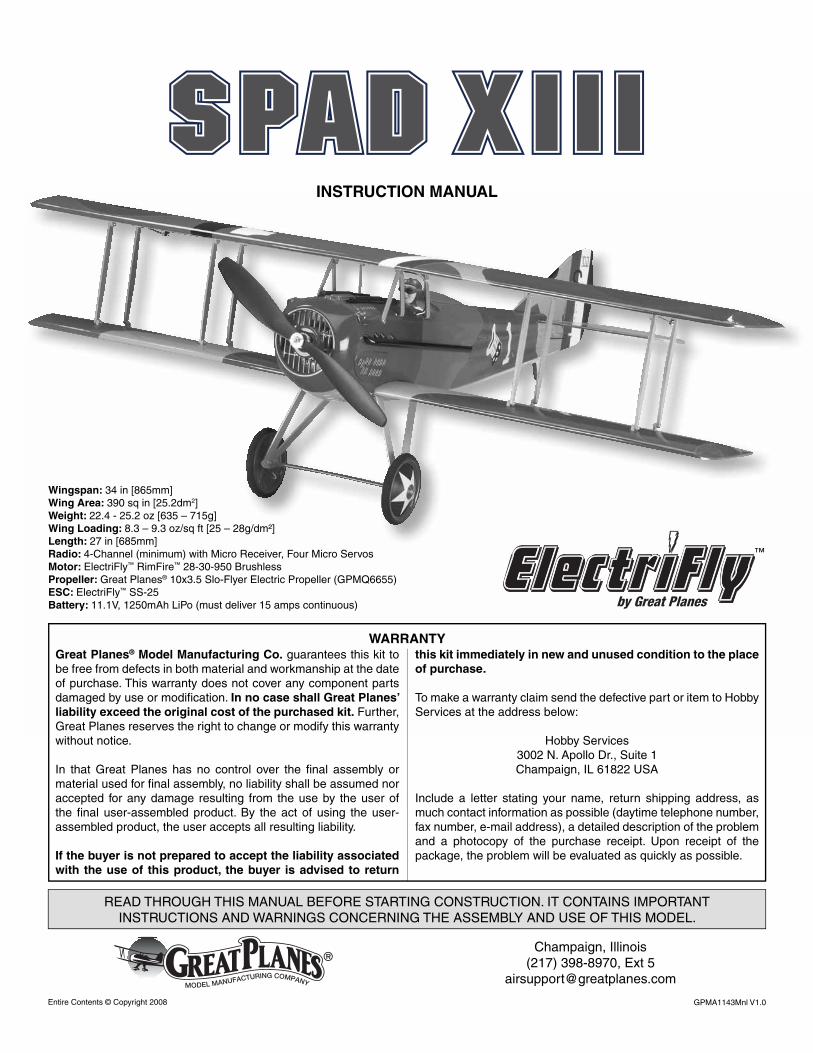
Wingspan: 34 in [865mm]Wing Area: 390 sq in [25.2dm2]Weight: 22.4 - 25.2 oz [635 – 715g]Wing Loading: 8.3 – 9.3 oz/sq ft [25 – 28g/dm²]Length: 27 in [685mm]Radio: 4-Channel (minimum) with Micro Receiver, Four Micro ServosMotor: ElectriFly™ RimFire™ 28-30-950 BrushlessPropeller: Great Planes® 10x3.5 Slo-Flyer Electric Propeller (GPMQ6655)ESC: ElectriFly™ SS-25Battery: 11.1V, 1250mAh LiPo (must deliver 15 amps continuous)
™
2
TABLE OF CONTENTS
INTRODUCTION ............................................................... 2
AMA .................................................................................. 2
SAFETY PRECAUTIONS ................................................. 3
LITHIUM BATTERY HANDLING AND USAGE ................ 3
REQUIRED ITEMS ............................................................ 3
Radio Equipment ....................................................... 3
Motor, ESC & Propeller .............................................. 3
Battery Pack & Accessories ....................................... 4
Adhesive and Building Supplies ................................. 4
Optional Supplies and Tools ....................................... 4
IMPORTANT BUILDING NOTES ...................................... 4
KIT INSPECTION .............................................................. 4
KIT CONTENTS ................................................................ 5
ORDERING REPLACEMENT PARTS .............................. 5
BEFORE YOU BEGIN ....................................................... 6
INSTALL THE TAIL............................................................ 6
Prepare for Tail Installation ......................................... 6
Install the Tail to the Fuselage .................................... 7
INSTALL THE MOTOR & ESC .......................................... 8
INSTALL THE ELEVATOR & RUDDER SERVOS .......... 10
PREPARE THE WINGS ................................................... 13
Install the Aileron Servos ......................................... 13
Install the Strut Mounts ............................................ 14
INSTALL THE WINGS ..................................................... 14
INSTALL THE LANDING GEAR ..................................... 16
INSTALL THE COWL & PROPELLER............................ 17
FINISH THE MODEL ....................................................... 17
GET THE MODEL READY TO FLY ................................. 18
Center Controls & Check Control Directions ............ 18
Set the Control Throws ............................................ 19
Balance the Model (C.G.)......................................... 20
Balance the Model Laterally ..................................... 20
PREFLIGHT .................................................................... 21
Identify Your Model ................................................... 21
Charge the Batteries ................................................ 21
Balance Propellers ................................................... 21
Range Check ........................................................... 21
MOTOR SAFETY PRECAUTIONS ................................. 21
AMA SAFETY CODE ...................................................... 21
CHECK LIST ................................................................... 22
FLYING ............................................................................ 22
Takeoff ..................................................................... 23
Flight ........................................................................ 23
Landing .................................................................... 23
INTRODUCTION
You’ll be proud to add the Great Planes SPAD XIII EP to your WWI hangar. This particular SPAD bears the markings of the famous 94th Aero Squadron, distinguished by their famous “hat in the ring.” The American 94th Aero Squadron scored 70 kills by the end of the war, and 26 of these are credited to their number one ace Captain Eddie Rickenbacker. You can now relive those days fi ghting German Fokker D.VII’s and DR.I’s in your backyard. Perform lazy eights, chandelles, hammer head stalls, and dizzying spins: the Great Planes SPAD XIII EP is stable enough to handle all of these with ease and confi dence. So grab a friend and let’s start a dog-fi ght!
Learn where the 94th Aero is today. Go to:
www.langley.af.mil/library/factsheets/
and click on “94th Fighter Squadron.”
For the latest technical updates or manual corrections to the SPAD XIII EP visit the Great Planes web site at www.greatplanes.com. Open the “Airplanes” link, and then select the SPAD XIII EP. If there is new technical information or changes to this model a “tech notice” box will appear in the upper left corner of the page.
AMA
We urge you to join the AMA (Academy of Model Aeronautics) and a local R/C club. The AMA is the governing body of model aviation and membership is required to fl y at AMA clubs. Though joining the AMA provides many benefi ts, one of the primary reasons to join is liability protection. Coverage is not limited to fl ying at contests or on the club fi eld. It even applies to fl ying at public demonstrations and air shows. Failure to comply with the Safety Code (excerpts printed in the back of the manual) may endanger insurance coverage. Additionally, training programs and instructors are available at AMA club sites to help you get started the right way. There are over 2,500 AMA chartered clubs across the country. Contact the AMA at the address or toll-free phone number below.
Academy of Model Aeronautics5151 East Memorial Drive
Muncie, IN 47302Tele: (800) 435-9262Fax (765) 741-0057
Or via the Internet at:www.modelaircraft.org
IMPORTANT!!! Two of the most important things you can do to preserve the radio controlled aircraft hobby are to avoid fl ying near full-scale aircraft and avoid fl ying near or over groups of people.
3
PROTECT YOUR MODEL, YOURSELF & OTHERS...FOLLOW THESE
IMPORTANT SAFETY PRECAUTIONS
1. Your SPAD XIII ARF should not be considered a toy, but rather a sophisticated, working model that functions very much like a full-size airplane. Because of its performance capabilities, the SPAD XIII, if not assembled and operated correctly, could possibly cause injury to yourself or spectators and damage to property.
2. You must assemble the model according to the instructions. Do not alter or modify the model, as doing so may result in an unsafe or unfl yable model. In a few cases the instructions may differ slightly from the photos. In those instances the written instructions should be considered as correct.
3. You must take time to build straight, true and strong.
4. You must use an R/C radio system that is in fi rst-class condition, and a correctly sized engine and components throughout the building process.
5. You must correctly install all R/C and other components so that the model operates correctly on the ground and in the air.
6. You must check the operation of the model before every fl ight to insure that all equipment is operating and that the model has remained structurally sound. Be sure to check clevises or other connectors often and replace them if they show any signs of wear or fatigue.
7. If you are not an experienced pilot or have not fl own this type of model before, we recommend that you get the assistance of an experienced pilot in your R/C club for your fi rst fl ights. If you’re not a member of a club, your local hobby shop has information about clubs in your area whose membership includes experienced pilots.
8. While this kit has been fl ight tested to exceed normal use, if the plane will be used for extremely high stress fl ying, such as racing, or if an engine larger than one in the recommended range is used, the modeler is responsible for taking steps to reinforce the high stress points and/or substituting hardware more suitable for the increased stress.
We, as the kit manufacturer, provide you with a top quality, thoroughly tested kit and instructions, but ultimately the quality and fl yability of your fi nished model depends on how you build it; therefore, we cannot in any way guarantee the performance of your completed model, and no representations are expressed or implied as to the performance or safety of your completed model.
Remember: Take your time and follow the instructions to end up with a well-built model that is straight and true.
LITHIUM BATTERY HANDLING AND USAGE
WARNING!! Read the entire instruction sheet included with the battery. Failure to follow all instructions could cause permanent damage to the battery and its surroundings, and cause bodily harm!
• ONLY use a LiPo approved charger. NEVER use a NiCd/NiMH peak charger!
• NEVER charge in excess of 4.20V per cell.• ONLY charge through the “charge” lead. NEVER charge
through the “discharge” lead.• NEVER charge at currents greater than 1C.• ALWAYS set charger’s output volts to match battery volts.• ALWAYS charge in a fi reproof location.• NEVER trickle charge.• NEVER allow battery temperature to exceed 150°F (65°C).• NEVER disassemble or modify pack wiring in any way
or puncture cells.• NEVER discharge below 2.5V per cell.• NEVER place on combustible materials or leave
unattended during charge or discharge.• ALWAYS KEEP OUT OF REACH OF CHILDREN.
REQUIRED ITEMS
This is a partial list of items required to fi nish the SPAD XIII EP. Order numbers are provided in parentheses.
Radio Equipment
A 4-channel radio system with four micro servos and a micro receiver are required for this plane. Many radio systems are suitable, but we have chosen the following for this build-up.
❏ Four Futaba® S3114 Micro HT Servo (FUTM0414) OR minimum 20oz-in torque micro servos
❏ Futaba R114F FM Micro Receiver (Low Band – FUTL0442, High Band – FUTL0443)
❏ Futaba FM Single Conversion Short Crystal(Low Band – FUTL62**, High Band – FUTL63**)
❏ One Y-harness (FUTM4130 or FUTM4135 fordigital servos)
❏ One Servo Mounting Screw Set (FUTM2550)
Motor, ESC & Propeller Recommendations
The SPAD XIII EP was tested extensively to fi nd the best “power package” that offers light weight, long fl ight time, and excellent thrust. The power system we have chosen has more than enough power to get you out of trouble. Choosing larger propellers will damage the motor and/or speed control. The order numbers for these are provided.
❏ Great Planes RimFire™ 28-30-950 Brushless Out-runner Motor (GPMG4560)
❏ Great Planes Silver Series 25A Brushless ESC 5V/2A BEC (GPMM1820)
❏ Great Planes 10x3.5 PowerFlow™ Propeller (GPMQ6655) (draws 15 amps max.)
❏ Great Planes 3.5mm Male/2.5mm Female Bullet Connector Adapters (GPMM3122)
❏ Great Planes 3mm to 5mm Prop Adapter (GPMQ4959)
Battery Pack & Accessories
❏ Great Planes LiPo 1250mAh 11.1V 15C Dischargew/Balance (GPMP0713)
❏ Great Planes LiPo 1500mAh 11.1V 15C Dischargew/ Balance (GPMP0717)
A LiPo-compatible charger is required for these batteries, along with a cell balancer. We recommend:
❏ Great Planes Equinox™ 1-5 cell LiPo cell balancer (GPMM3160)
❏ Great Planes PolyCharge4™ LiPo battery charger (GPMM3015) OR Great Planes PolyCharge DC LiPo battery charger (GPMM3010)
Required Adhesive & Building Supplies
This is the list of adhesive and building supplies required to fi nish the SPAD XIII EP.
❏ 1/2 oz. [15g] Thin Pro™ CA (GPMR6001)❏ 1/2 oz. [15g] Medium Pro CA+ (GPMR6007)❏ R/C-56 Glue 4oz (JOZR5007)❏ Denatured alcohol❏ Drill bits: #55 [1.3mm], 1/16" [1.6mm]❏ #1 Hobby knife (HCAR0105)❏ #11 blades (5-pack, HCAR0211)❏ Hobbico® Steel T-Pins 1" (100) (HCAR5100)❏ Great Planes Pro Thread locker (GPMR6060)❏ CA applicator tips (HCAR3780)❏ 220 grit sandpaper❏ Bru Line® hemostat – curved 5-1/2" (BRUR1303)
Optional Supplies & Tools
Here is a list of optional tools mentioned in the manual that will help you build the SPAD XIII EP.
❏ 21ST Century® sealing iron (COVR2700) ❏ 21ST Century iron cover (COVR2702)❏ 2 oz [57g] spray CA activator (GPMR6035)❏ 4 oz [113g] aerosol CA activator (GPMR634)❏ Masking tape (TOPR8018)❏ CA debonder (GPMR6039)
❏ Great Planes Double-Sided Servo Tape 1"x3' (GPMQ4442)❏ Panel Line Pen (TOPQ2510)❏ Rotary tool (Dremel®) with cutoff wheel❏ Hobbico Flexible 18" Ruler Stainless Steel (HCAR0460)❏ Builder’s Triangle Set (HCAR0480)❏ AccuThrow™ Defl ection Gauge (GPMR2405)❏ Hobbico 12 Volt DC power supply (HCAP0250)❏ Green 3M® Scotch Brite™
IMPORTANT BUILDING NOTES
• When you see the term test fi t in the instructions, it means that you should fi rst position the part on the assembly without using any glue, then slightly modify or custom fi t the part as necessary for the best fi t.
• Whenever the term glue is written you should rely upon your experience to decide what type of glue to use. When a specifi c type of adhesive works best for that step, the instructions will make a recommendation.
• Photos and sketches are placed before the step they refer to. Frequently you can study photos in following steps to get another view of the same parts.
• The stabilizer and wing incidences and motor thrust angles have been factory-built into this model. However, some technically-minded modelers may wish to check these measurements anyway. To view this information visit the web site at www.greatplanes.com and click on “Technical Data.” Due to manufacturing tolerances which will have little or no effect on the way your model will fl y, please expect slight deviations between your model and the published values.
KIT INSPECTION
Before starting to build inspect the parts to make sure they are of acceptable quality. If any parts are missing or are not of acceptable quality, or if you need assistance with assembly, contact Product Support. When reporting defective or missing parts, use the part names exactly as they are written in the Kit Contents list.
Great Planes Product Support3002 N. Apollo Drive, Suite 1
Champaign, IL 61822Telephone: (217) 398-8970, ext. 5
Fax: (217) 398-7721E-mail: [email protected]
4

ORDERING REPLACEMENT PARTS
Replacement parts for the ElectriFly SPAD XIII EP are available using the order numbers in the Replacement Parts List that follows. The fastest, most economical service can be provided by your hobby dealer or mail-order company.
To locate a hobby dealer, visit the Great Planes web site at www.greatplanes.com. Choose “Where to Buy” at the bottom of the menu on the left side of the page. Follow the instructions provided on the page to locate a U.S., Canadian or International dealer.
Parts may also be ordered directly from Hobby Services by calling (217) 398-0007, or via facsimile at (217) 398-7721, but full retail prices and shipping and handling charges will apply. Illinois and Nevada residents will also be charged sales tax. If ordering via fax, include a Visa or MasterCard number and expiration date for payment.
Mail parts orders and payments by personal check to:
Hobby Services3002 N Apollo Drive, Suite 1
Champaign IL 61822
Be certain to specify the order number exactly as listed in the Replacement Parts List. Payment by credit card or personal check only; no C.O.D.
If additional assistance is required for any reason contact Product Support by e-mail at [email protected], or by telephone at (217) 398-8970.
Replacement Parts List Order # Description How to Purchase Missing pieces ....... Contact Product Support Instruction manual . Contact Product Support Full-size plans .......................... Not available
Contact your hobby supplier for the following parts:
GPMA3100 Top WingGPMA3101 Bottom WingGPMA3102 Fuselage w/Belly PanGPMA3103 Tail Surface SetGPMA3104 Wing Struts and Cabanes SetGPMA3105 Landing Gear Set w/WheelsGPMA3106 Cowl, Exhaust, Guns, Battery & Servo HatchesGPMA2997 WWI Pilot FigureGPMA3108 Motor Mount and Hardware Bag
KIT CONTENTS
1
62
5
4
9
8
7
3
55
1. Fuselage w/Cowl, Battery Hatch 2. Wheels 3. Horizontal Stabilizer w/Elevators
4. Fin w/Rudder 5. Cabane Struts 6. Interplane Struts
7. Landing Gear 8. Upper Wing w/Ailerons 9. Lower Wing

666
BEFORE YOU BEGIN
Before you begin assembling your model, inspect it for wrinkled covering and areas where the covering may not be tacked down adequately. Areas like the servo bay openings, the radio antenna hole (bottom of fuse), and the slots for the horizontal stabilizer and fi n should be tacked down before trimming them with a knife. The covering should be tacked down to the wood using just enough heat to soften the adhesive backing. Low heat should be enough to accomplish this. More heat may be required to begin to tighten the covering.
WARNINGS: • Do not over shrink the covering or it will cause the control
surfaces or wings to twist• Do not iron over decals• Use only LOW heat over trim
INSTALL THE TAIL
Prepare for Tail Installation
❏ 1. Locate the wooden 3 x 20mm dowels. Holes are provided in the leading edge of the lower wing. Test fi t each dowel making sure that the dowel sticks out 1/4" [6mm] from the LE of the wing. When you are satisfi ed with the fi t, wick 5 to 7 drops of thin CA into the dowel joint.
❏ 2. Using a 4-40 x 3/4" machine screw with a washer, temporarily install the lower wing to the fuselage. Fitting the lower wing will help you align the horizontal tail.
❏ 3. Lay the pre-hinged horizontal stabilizer assembly on a fl at surface. Make sure that the elevators lie fl at on the table and that the stab does not have any twist in it. Any twist can be easily corrected at this point using a covering iron on a medium heat setting. Twist the surface to the desired position and heat the covering until it begins to shrink.
❏ 4. Insert the vertical fi n into the top of the horizontal stabilizer. Align the fi n vertically and apply a bead of medium CA to both sides of the joint.
7
Install the Tail to the Fuselage
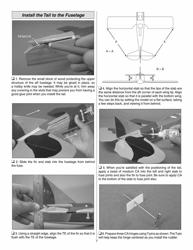
❏ 1. Remove the small block of wood protecting the upper structure of the aft fuselage. It may be glued in place, so a hobby knife may be needed. While you’re at it, trim away any covering in the slots that may prevent you from having a good glue joint when you install the tail.
❏ 2. Slide the fi n and stab into the fuselage from behind the fuse.
❏ 3. Using a straight edge, align the TE of the fi n so that it is fl ush with the TE of the fuselage.
A A
A = A
B
B = B
B
❏ 4. Align the horizontal stab so that the tips of the stab are the same distance from the aft corner of each wing tip. Align the horizontal stab so that it is parallel with the bottom wing. You can do this by setting the model on a fl at surface, taking a few steps back, and viewing it from behind.
❏ 5. When you’re satisfi ed with the positioning of the tail, apply a bead of medium CA into the left and right stab to fuse joints and also the fi n to fuse joint. Be sure to apply CA to the bottom of the stab to fuse joint also.
❏ 6. Prepare three CA hinges using T-pins as shown. The T-pin will help keep the hinge centered as you install the rudder.
8
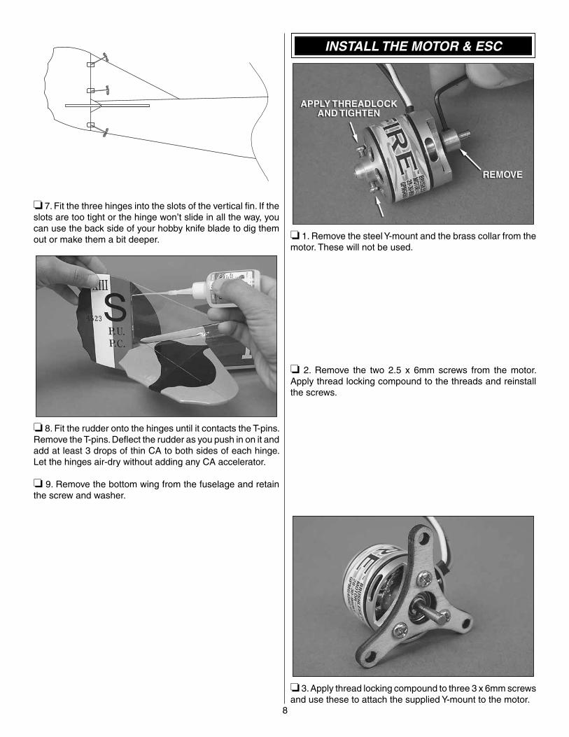
❏ 7. Fit the three hinges into the slots of the vertical fi n. If the slots are too tight or the hinge won’t slide in all the way, you can use the back side of your hobby knife blade to dig them out or make them a bit deeper.
❏ 8. Fit the rudder onto the hinges until it contacts the T-pins. Remove the T-pins. Defl ect the rudder as you push in on it and add at least 3 drops of thin CA to both sides of each hinge. Let the hinges air-dry without adding any CA accelerator.
❏ 9. Remove the bottom wing from the fuselage and retain the screw and washer.
INSTALL THE MOTOR & ESC
❏ 1. Remove the steel Y-mount and the brass collar from the motor. These will not be used.
❏ 2. Remove the two 2.5 x 6mm screws from the motor. Apply thread locking compound to the threads and reinstall the screws.
❏ 3. Apply thread locking compound to three 3 x 6mm screws and use these to attach the supplied Y-mount to the motor.

9
❏ 4. Locate three 4-40 x 1" machine screws, one 10mm standoff tube, two 14mm standoff tubes, and nine washers. Note: Unlike the 3x25mm size, the 4-40x1" screws have a coarse thread pitch. Test-fi t, and use the screws that thread into the blind nuts properly. Apply thread locking compound to the screws and install the motor to the fi rewall as shown with the 10mm standoff tube in the bottom position. Make sure that the motor wires are routed through the left side of the fuse.
❏ 5. After you have tightened the screws, rotate the motor by hand to check for free rotation. If the motor does not rotate freely, you may have to remove it and use sandpaper (or a Dremel tool) to grind down the bottom of the battery tray or any obstruction.
❏ 6. Install three 3.5mm male/2mm female bullet connector adapters onto the ESC motor leads (GPMM3122).
❏ 7. Coat the underside of the battery tray with thin CA as shown. Apply a few thin lines of CA and dab up the excess CA with a paper towel. Allow the CA to dry. This will prepare the surface of the battery tray where the ESC and receiver will mount.
❏ 8. From the supplied double-sided foam tape, cut a 1" [25mm] piece and apply it to the back side of your ESC. Remove the backing paper and stick the ESC to the back of the battery tray as shown. Route the battery leads into the battery compartment and connect the motor leads.
❏ 9. Prepare the battery strap using the supplied hook and loop material as shown. Overlap the two strips by 1-1/4" [32mm].

10
❏ 10. Install the hook and loop battery strap on the battery tray from the bottom.
INSTALL THE ELEVATOR & RUDDER SERVOS
❏ 1. Use your radio to center your servos. With the servos centered, reposition each servo arm so that one of the two long arms is perpendicular to the servo case. You will need one servo with the arm on the left side of the case and one with the arm on the right side of the case. Clip off the remaining unused arms.
❏ 2. Use a #55 [1.3mm] drill bit and enlarge the servo arm holes. If you don’t have a #55 drill bit, use your hobby knife to enlarge the holes.
❏ 3. Locate two Screw-Lock pushrod connectors, two 2-56 x 3/16" screws, and two plastic locking collars. Install these on the rudder and elevator servos in the holes shown if you are using Futaba micro servos.
❏ 4. Install the rudder and elevator servos as shown with the servo leads facing aft. Do not run the leads forward. They will interfere with the operation of the motor.
❏ 5. Plug a Y-harness into your receiver in the aileron channel. This is Channel 1 on most Futaba radios. Apply a 1" [25mm] piece of double-sided foam tape to the back side of your receiver.
If you are using a 2.4G radio,you should omit the next step.
❏ 6. Find the antenna support plate beneath the covering. Find the pre-drilled hole in the center of the plate and use a hobby knife or a T-pin to poke through the covering.
11
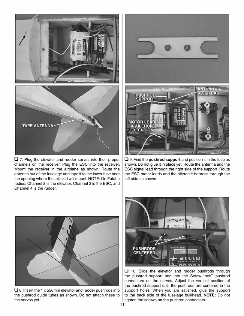
❏ 7. Plug the elevator and rudder servos into their proper channels on the receiver. Plug the ESC into the receiver. Mount the receiver in the airplane as shown. Route the antenna out of the fuselage and tape it to the lower fuse near the opening where the tail skid will mount. NOTE: On Futaba radios, Channel 2 is the elevator, Channel 3 is the ESC, and Channel 4 is the rudder.
❏ 8. Insert the 1 x 550mm elevator and rudder pushrods into the pushrod guide tubes as shown. Do not attach these to the servos yet.
❏ 9. Find the pushrod support and position it in the fuse as shown. Do not glue it in place yet. Route the antenna and the ESC signal lead through the right side of the support. Route the ESC motor leads and the aileron Y-harness through the left side as shown.
❏ 10. Slide the elevator and rudder pushrods through the pushrod support and into the Screw-Lock™ pushrod connectors on the servos. Adjust the vertical position of the pushrod support until the pushrods are centered in the support holes. When you are satisfi ed, glue the support to the back side of the fuselage bulkhead. NOTE: Do not tighten the screws on the pushrod connectors.
12
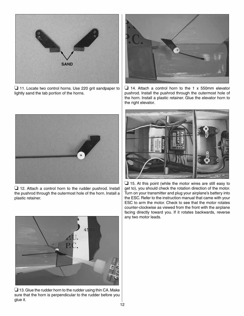
❏ 11. Locate two control horns. Use 220 grit sandpaper to lightly sand the tab portion of the horns.
❏ 12. Attach a control horn to the rudder pushrod. Install the pushrod through the outermost hole of the horn. Install a plastic retainer.
❏ 13. Glue the rudder horn to the rudder using thin CA. Make sure that the horn is perpendicular to the rudder before you glue it.
❏ 14. Attach a control horn to the 1 x 550mm elevator pushrod. Install the pushrod through the outermost hole of the horn. Install a plastic retainer. Glue the elevator horn to the right elevator.
❏ 15. At this point (while the motor wires are still easy to get to), you should check the rotation direction of the motor. Turn on your transmitter and plug your airplane’s battery into the ESC. Refer to the instruction manual that came with your ESC to arm the motor. Check to see that the motor rotates counter-clockwise as viewed from the front with the airplane facing directly toward you. If it rotates backwards, reverse any two motor leads.
13
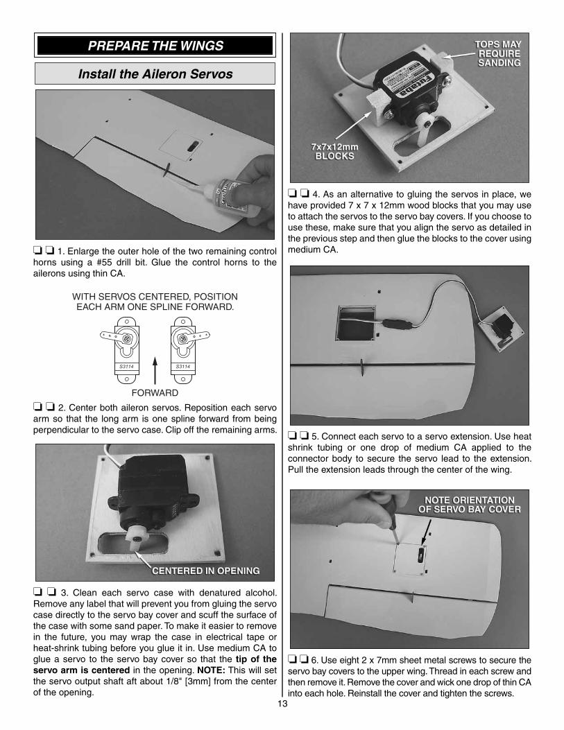
PREPARE THE WINGS
Install the Aileron Servos
❏ ❏ 1. Enlarge the outer hole of the two remaining control horns using a #55 drill bit. Glue the control horns to the ailerons using thin CA.
WITH SERVOS CENTERED, POSITIONEACH ARM ONE SPLINE FORWARD.
FORWARD
❏ ❏ 2. Center both aileron servos. Reposition each servo arm so that the long arm is one spline forward from being perpendicular to the servo case. Clip off the remaining arms.
❏ ❏ 3. Clean each servo case with denatured alcohol. Remove any label that will prevent you from gluing the servo case directly to the servo bay cover and scuff the surface of the case with some sand paper. To make it easier to remove in the future, you may wrap the case in electrical tape or heat-shrink tubing before you glue it in. Use medium CA to glue a servo to the servo bay cover so that the tip of the servo arm is centered in the opening. NOTE: This will set the servo output shaft aft about 1/8" [3mm] from the center of the opening.
❏ ❏ 4. As an alternative to gluing the servos in place, we have provided 7 x 7 x 12mm wood blocks that you may use to attach the servos to the servo bay covers. If you choose to use these, make sure that you align the servo as detailed in the previous step and then glue the blocks to the cover using medium CA.
❏ ❏ 5. Connect each servo to a servo extension. Use heat shrink tubing or one drop of medium CA applied to the connector body to secure the servo lead to the extension. Pull the extension leads through the center of the wing.
❏ ❏ 6. Use eight 2 x 7mm sheet metal screws to secure the servo bay covers to the upper wing. Thread in each screw and then remove it. Remove the cover and wick one drop of thin CA into each hole. Reinstall the cover and tighten the screws.
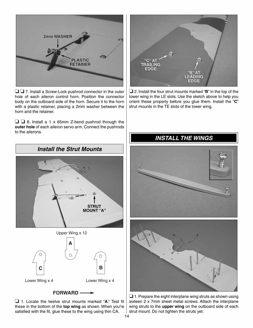
❏ ❏ 7. Install a Screw-Lock pushrod connector in the outer hole of each aileron control horn. Position the connector body on the outboard side of the horn. Secure it to the horn with a plastic retainer, placing a 2mm washer between the horn and the retainer.
❏ ❏ 8. Install a 1 x 65mm Z-bend pushrod through the outer hole of each aileron servo arm. Connect the pushrods to the ailerons.
Install the Strut Mounts
A
FORWARD
Upper Wing x 12
Lower Wing x 4 Lower Wing x 4
BC
❏ 1. Locate the twelve strut mounts marked “A.” Test fi t these in the bottom of the top wing as shown. When you’re satisfi ed with the fi t, glue these to the wing using thin CA.
❏ 2. Install the four strut mounts marked “B” in the top of the lower wing in the LE slots. Use the sketch above to help you orient these properly before you glue them. Install the “C” strut mounts in the TE slots of the lower wing.
INSTALL THE WINGS
❏ 1. Prepare the eight interplane wing struts as shown using sixteen 2 x 7mm sheet metal screws. Attach the interplane wing struts to the upper wing on the outboard side of each strut mount. Do not tighten the struts yet.
14

15
❏ 2. Test fi t the cabane struts to the fuselage as shown. Use a 1/16" [1.6mm] drill bit to drill a hole for the screw where shown. NOTE: Gluing these in place is optional and can be done after you are assured of a proper fi t of the upper wing.
❏ 3. Install the upper wing using six 2 x 7mm sheet metal screws. Install two 2 x 7mm sheet metal screws in the lower legs of the forward cabanes.
❏ 4. Route the aileron servo leads through the slot in the fuselage. Use a tie strap to secure them to the cabane strut.
❏ 5. Connect the aileron leads to the Y-harness. Use a drop of glue to attach the aileron Y-harness to the fuse side. Place it in a location that will neatly keep wires away from the pushrods.
❏ 6. Use a 4-40 x 3/4" machine screw and washer to attach the lower wing to the fuse.
❏ 7. Attach the interplane wing struts to the lower wing.
16
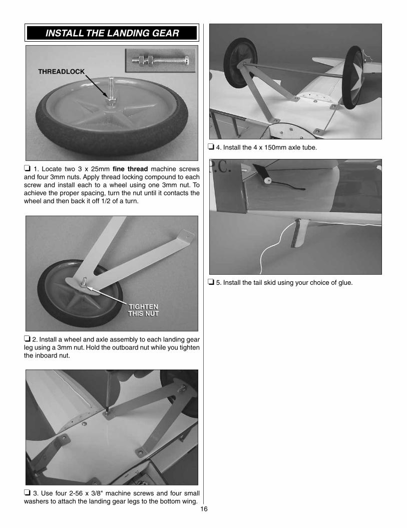
INSTALL THE LANDING GEAR
❏ 1. Locate two 3 x 25mm fi ne thread machine screws and four 3mm nuts. Apply thread locking compound to each screw and install each to a wheel using one 3mm nut. To achieve the proper spacing, turn the nut until it contacts the wheel and then back it off 1/2 of a turn.
❏ 2. Install a wheel and axle assembly to each landing gear leg using a 3mm nut. Hold the outboard nut while you tighten the inboard nut.
❏ 3. Use four 2-56 x 3/8" machine screws and four small washers to attach the landing gear legs to the bottom wing.
❏ 4. Install the 4 x 150mm axle tube.
❏ 5. Install the tail skid using your choice of glue.

17
INSTALL THE COWL & PROPELLER
❏ 1. Install the cowl. Make sure that the cowl magnets are fi rmly engaged and that the cowl is secure. NOTE: The heads of the motor screws may interfere with the cowl’s grill. Please trim the grill if this is the case.
❏ 2. Balance your propeller using the method described in the “Balance Propellers” section.
❏ 3. Fit a 3mm to 5mm prop adapter (GPMQ4959) to the motor shaft. Install the propeller (GPMQ6655), the prop washer, and the prop nut onto the prop adapter. Tighten the prop nut.
FINISH THE MODEL
The actual SPAD XIII was covered in fabric and had a “doped” fi nish brushed onto it. This gave it a semi-gloss or dull fi nish. Depending on how much you care to detail or personalize your SPAD, you may choose to replicate this fi nish. Use some green 3M Scotch Brite™ to scuff the surface of the plastic fi lm covering, working in a fore-aft motion. This will dull the fi nish and simulate brush marks. It also gives your model a “weathered” look. Try working in an inconspicuous area fi rst.
❏ 1. Trim the covering from the holes in the fuse where the left and right exhaust stacks will mount.

18
❏ 2. Apply glue to the exhaust stacks and install them onto the fuse. R/C-56 Glue (JOZR5007) is recommended.
❏ 3. Turn the model over and glue the belly fairing to the bottom wing using R/C-56 Glue. Medium CA is also suitable, but only one small drop should be used at the LE former and at the TE former so that the panel can be removed later. Install the fairing with the hole facing aft.
❏ 4. Apply a strip of double-sided tape to the bottom of the pilot fi gure and attach it to the cockpit fl oor.
GET THE MODEL READY TO FLY
Center the Controls & Check the Control Directions
WARNING: Once the battery is connected to the ESC, stay clear of the propeller!
❏ 1. Turn on the transmitter, center the trims, and move the throttle stick all the way down. Plug your airplane’s battery into the ESC and check to see that all servo arms are positioned properly. If necessary, remove the servo arms from the servos and reposition them so they are centered. Reinstall the screws that hold on the servo arms.
❏ 2. With the transmitter and receiver still on, check all the control surfaces to see that they are centered. If necessary, adjust the pushrods to center the control surfaces. Apply thread locking compound to the locking screw threads and tighten all of the Screw-Lock pushrod connectors.
❏ 3. Install the servo bay hatch.
19
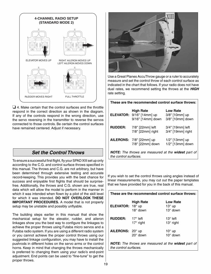
FULL THROTTLERUDDER MOVES RIGHT
ELEVATOR MOVES UP RIGHT AILERON MOVES UPLEFT AILERON MOVES DOWN
4-CHANNEL RADIO SETUP(STANDARD MODE 2)
❏ 4. Make certain that the control surfaces and the throttle respond in the correct direction as shown in the diagram. If any of the controls respond in the wrong direction, use the servo reversing in the transmitter to reverse the servos connected to those controls. Be certain the control surfaces have remained centered. Adjust if necessary.
Set the Control Throws
To ensure a successful fi rst fl ight, fl y your SPAD XIII set up only according to the C.G. and control surface throws specifi ed in this manual. The throws and C.G. are not arbitrary, but have been determined through extensive testing and accurate record-keeping. This provides you with the best chance for success and enjoyable fi rst fl ights that should be surprise-free. Additionally, the throws and C.G. shown are true, real data which will allow the model to perform in the manner in which it was intended when fl own by a pilot of the skill level for which it was intended. DO NOT OVERLOOK THESE IMPORTANT PROCEDURES. A model that is not properly setup may be unstable and possibly unfl yable.
The building steps earlier in this manual that show the mechanical setup for the elevator, rudder, and aileron linkages show you the best way to confi gure the linkages to achieve the proper throws using Futaba micro servos and a Futaba radio system. If you are using a different radio system or you cannot achieve the proper control throws using our suggested linkage confi guration, you may have to install the pushrods in different holes on the servo arms or the control horns. Keep in mind that changing the throws mechanically is preferred to changing them using your radio’s end-point adjustment. End points can be used to “fi ne-tune” to get the proper throws.
Use a Great Planes AccuThrow gauge or a ruler to accurately measure and set the control throw of each control surface as indicated in the chart that follows. If your radio does not have dual rates, we recommend setting the throws at the HIGH rate setting.
These are the recommended control surface throws:
High Rate Low RateELEVATOR: 9/16" [14mm] up 3/8" [10mm] up 9/16" [14mm] down 3/8" [10mm] down
RUDDER: 7/8" [22mm] left 3/4" [19mm] left 7/8" [22mm] right 3/4" [19mm] right
AILERONS: 7/8" [22mm] up 1/2" [13mm] up 7/8" [22mm] down 1/2" [13mm] down
NOTE: The throws are measured at the widest part of the control surfaces.
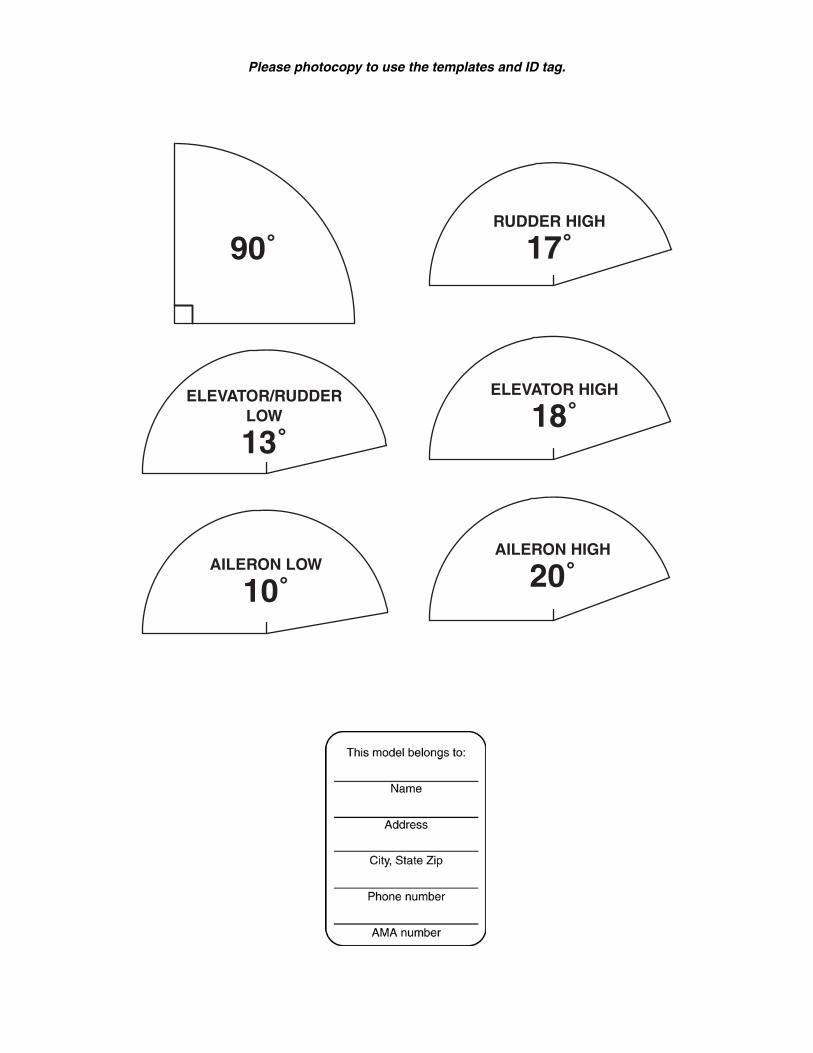
If you wish to set the control throws using angles instead of linear measurements, you may cut out the paper templates that we have provided for you in the back of this manual.
These are the recommended control surface throws:
High Rate Low RateELEVATOR: 18° up 13° up 18° down 13° down
RUDDER: 17° left 13° left 17° right 13° right
AILERONS: 20° up 10° up 20° down 10° down
NOTE: The throws are measured at the widest part of the control surfaces.
20
Balance the Model (C.G.)
❏ 1. At this stage the model should be in ready-to-fl y condition with all of the systems in place including the motor, landing gear, radio system, battery, and all hatches. Place the battery in the battery compartment but do not connect it.
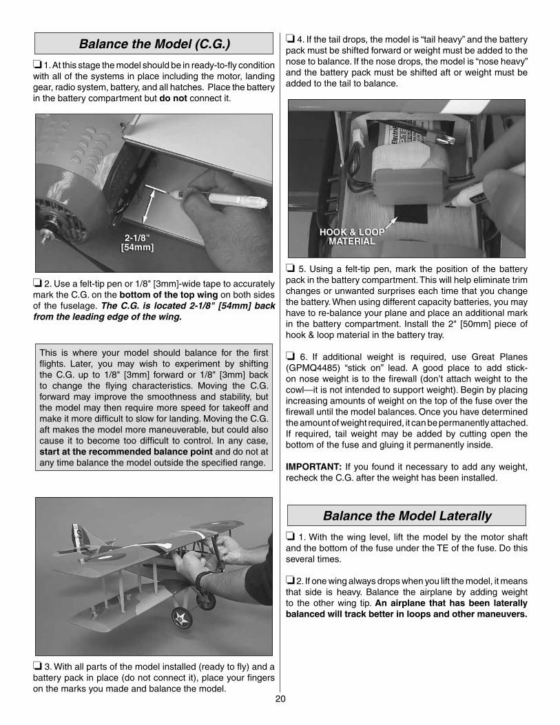
❏ 2. Use a felt-tip pen or 1/8" [3mm]-wide tape to accurately mark the C.G. on the bottom of the top wing on both sides of the fuselage. The C.G. is located 2-1/8" [54mm] back from the leading edge of the wing.
This is where your model should balance for the fi rst fl ights. Later, you may wish to experiment by shifting the C.G. up to 1/8" [3mm] forward or 1/8" [3mm] back to change the fl ying characteristics. Moving the C.G. forward may improve the smoothness and stability, but the model may then require more speed for takeoff and make it more diffi cult to slow for landing. Moving the C.G. aft makes the model more maneuverable, but could also cause it to become too diffi cult to control. In any case, start at the recommended balance point and do not at any time balance the model outside the specifi ed range.
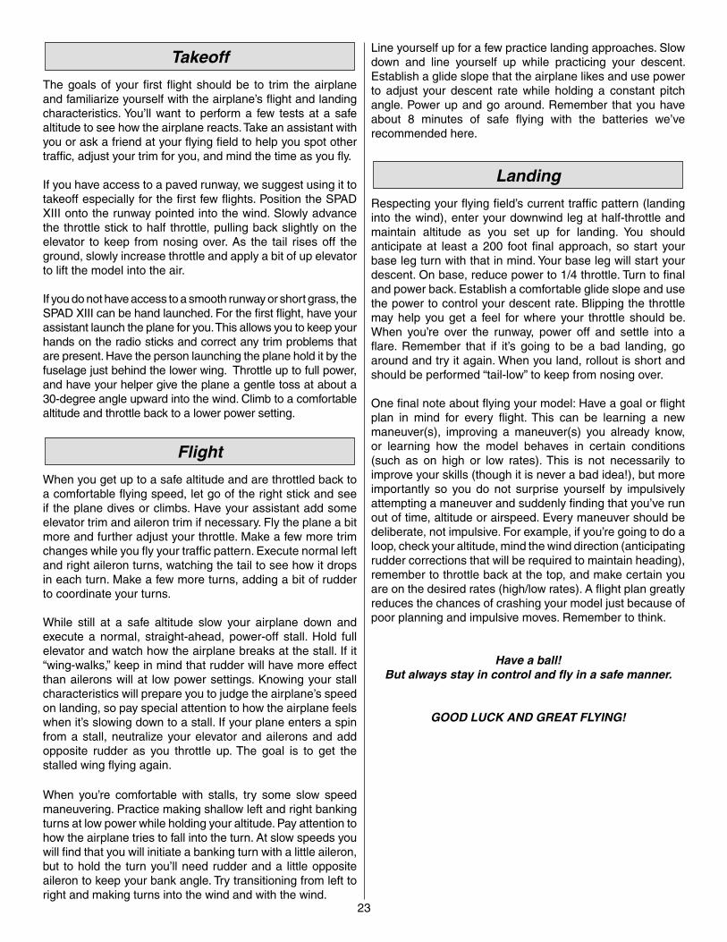
❏ 3. With all parts of the model installed (ready to fl y) and a battery pack in place (do not connect it), place your fi ngers on the marks you made and balance the model.
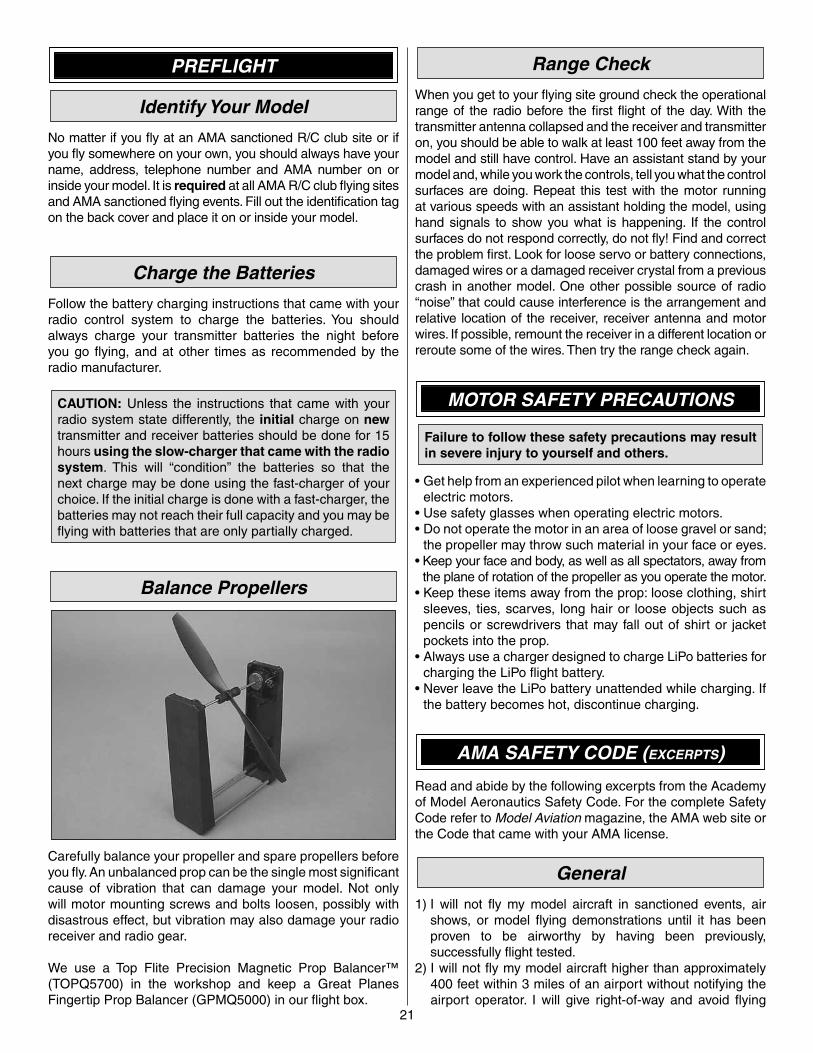
❏ 4. If the tail drops, the model is “tail heavy” and the battery pack must be shifted forward or weight must be added to the nose to balance. If the nose drops, the model is “nose heavy” and the battery pack must be shifted aft or weight must be added to the tail to balance.
❏ 5. Using a felt-tip pen, mark the position of the battery pack in the battery compartment. This will help eliminate trim changes or unwanted surprises each time that you change the battery. When using different capacity batteries, you may have to re-balance your plane and place an additional mark in the battery compartment. Install the 2" [50mm] piece of hook & loop material in the battery tray.
❏ 6. If additional weight is required, use Great Planes (GPMQ4485) “stick on” lead. A good place to add stick-on nose weight is to the fi rewall (don’t attach weight to the cowl—it is not intended to support weight). Begin by placing increasing amounts of weight on the top of the fuse over the fi rewall until the model balances. Once you have determined the amount of weight required, it can be permanently attached. If required, tail weight may be added by cutting open the bottom of the fuse and gluing it permanently inside.
IMPORTANT: If you found it necessary to add any weight, recheck the C.G. after the weight has been installed.
Balance the Model Laterally
❏ 1. With the wing level, lift the model by the motor shaft and the bottom of the fuse under the TE of the fuse. Do this several times.
❏ 2. If one wing always drops when you lift the model, it means that side is heavy. Balance the airplane by adding weight to the other wing tip. An airplane that has been laterally balanced will track better in loops and other maneuvers.
21
PREFLIGHT
Identify Your Model
No matter if you fl y at an AMA sanctioned R/C club site or if you fl y somewhere on your own, you should always have your name, address, telephone number and AMA number on or inside your model. It is required at all AMA R/C club fl ying sites and AMA sanctioned fl ying events. Fill out the identifi cation tag on the back cover and place it on or inside your model.
Charge the Batteries
Follow the battery charging instructions that came with your radio control system to charge the batteries. You should always charge your transmitter batteries the night before you go fl ying, and at other times as recommended by the radio manufacturer.
CAUTION: Unless the instructions that came with your radio system state differently, the initial charge on new transmitter and receiver batteries should be done for 15 hours using the slow-charger that came with the radio system. This will “condition” the batteries so that the next charge may be done using the fast-charger of your choice. If the initial charge is done with a fast-charger, the batteries may not reach their full capacity and you may be fl ying with batteries that are only partially charged.
Balance Propellers
Carefully balance your propeller and spare propellers before you fl y. An unbalanced prop can be the single most signifi cant cause of vibration that can damage your model. Not only will motor mounting screws and bolts loosen, possibly with disastrous effect, but vibration may also damage your radio receiver and radio gear.
We use a Top Flite Precision Magnetic Prop Balancer™ (TOPQ5700) in the workshop and keep a Great Planes Fingertip Prop Balancer (GPMQ5000) in our fl ight box.
Range Check
When you get to your fl ying site ground check the operational range of the radio before the fi rst fl ight of the day. With the transmitter antenna collapsed and the receiver and transmitter on, you should be able to walk at least 100 feet away from the model and still have control. Have an assistant stand by your model and, while you work the controls, tell you what the control surfaces are doing. Repeat this test with the motor running at various speeds with an assistant holding the model, using hand signals to show you what is happening. If the control surfaces do not respond correctly, do not fl y! Find and correct the problem fi rst. Look for loose servo or battery connections, damaged wires or a damaged receiver crystal from a previous crash in another model. One other possible source of radio “noise” that could cause interference is the arrangement and relative location of the receiver, receiver antenna and motor wires. If possible, remount the receiver in a different location or reroute some of the wires. Then try the range check again.
MOTOR SAFETY PRECAUTIONS
Failure to follow these safety precautions may result in severe injury to yourself and others.
• Get help from an experienced pilot when learning to operate electric motors.
• Use safety glasses when operating electric motors.• Do not operate the motor in an area of loose gravel or sand;
the propeller may throw such material in your face or eyes.• Keep your face and body, as well as all spectators, away from
the plane of rotation of the propeller as you operate the motor.• Keep these items away from the prop: loose clothing, shirt
sleeves, ties, scarves, long hair or loose objects such as pencils or screwdrivers that may fall out of shirt or jacket pockets into the prop.
• Always use a charger designed to charge LiPo batteries for charging the LiPo fl ight battery.
• Never leave the LiPo battery unattended while charging. If the battery becomes hot, discontinue charging.
AMA SAFETY CODE (EXCERPTS)
Read and abide by the following excerpts from the Academy of Model Aeronautics Safety Code. For the complete Safety Code refer to Model Aviation magazine, the AMA web site or the Code that came with your AMA license.
General
1) I will not fl y my model aircraft in sanctioned events, air shows, or model fl ying demonstrations until it has been proven to be airworthy by having been previously, successfully fl ight tested.
2) I will not fl y my model aircraft higher than approximately 400 feet within 3 miles of an airport without notifying the airport operator. I will give right-of-way and avoid fl ying

22
in the proximity of full-scale aircraft. Where necessary, an observer shall be utilized to supervise fl ying to avoid having models fl y in the proximity of full-scale aircraft.
3) Where established, I will abide by the safety rules for the fl ying site I use, and I will not willfully and deliberately fl y my models in a careless, reckless and/or dangerous manner.
5) I will not fl y my model unless it is identifi ed with my name and address or AMA number, on or in the model. Note: This does not apply to models while being fl own indoors.
7) I will not operate models with pyrotechnics (any device that explodes, burns, or propels a projectile of any kind).
Radio Control
1) I will have completed a successful radio equipment ground check before the fi rst fl ight of a new or repaired model.
2) I will not fl y my model aircraft in the presence of spectators until I become a qualifi ed fl ier, unless assisted by an experienced helper.
3) At all fl ying sites a straight or curved line(s) must be established in front of which all fl ying takes place with the other side for spectators. Only personnel involved with fl ying the aircraft are allowed at or in the front of the fl ight line. Intentional fl ying behind the fl ight line is prohibited.
4) I will operate my model using only radio control frequencies currently allowed by the Federal Communications Commission.
5) I will not knowingly operate my model within three miles of any pre-existing fl ying site except in accordance with the frequency sharing agreement listed [in the complete AMA Safety Code].
9) Under no circumstances may a pilot or other person touch a powered model in fl ight; nor should any part of the model other than the landing gear, intentionally touch the ground, except while landing.
CHECK LIST
During the last few moments of preparation your mind may be elsewhere anticipating the excitement of the fi rst fl ight. Because of this, you may be more likely to overlook certain checks and procedures that should be performed before the model is fl own. To help avoid this, a check list is provided to make sure these important areas are not overlooked. Many are covered in the instruction manual, so where appropriate, refer to the manual for complete instructions. Be sure to check the items off as they are completed.
❏ 1. Check the motor for secure attachment.❏ 2. Check the cowl for secure attachment and proper
alignment.❏ 3. Balance your propeller (and spare propellers).❏ 4. Tighten the propeller nut and check to make sure that
a prop washer is in place.❏ 5. Rotate the propeller a full turn. Check for free rotation
of the prop.❏ 6. Check the wheels for free rotation, the axles and landing
gear for security, and add a drop of light machine oil to the axles.
❏ 7. Make sure all hinges are securely glued in place.❏ 8. Check the control horns for secure attachment to the
control surfaces.❏ 9. Pull/push on each of the pushrods and check to see
that the adjustable pushrod connectors do not slip.❏ 10. Check the servo arms for secure attachment and make
sure that the arm screws are in place and are tight.❏ 11. Reinforce holes for wood screws with thin CA where
appropriate (servo mounting screws, etc.).❏ 12. Check that all servo connectors are fully plugged into
their respective channels on the receiver.❏ 13. Make sure any servo extension cords you may have
used do not interfere with other systems (servo arms, pushrods, etc.).
❏ 14. Check the receiver for secure attachment. This must not be “stuffed into place.”
❏ 15. Balance your model laterally as explained in the instructions.
❏ 16. Check the C.G. according to the measurements provided in the manual.
❏ 17. Place your name, address, AMA number and telephone number on or inside your model.
❏ 18. Fully charge your transmitter battery and check the battery voltage after it is charged.
❏ 19. Range-check your radio at the fl ying fi eld.❏ 20. Confi rm that all controls operate in the correct
direction and the throws are set up according to the manual.
❏ 21. If you wish to photograph your model, do so before your fi rst fl ight.
FLYING
CAUTION (THIS APPLIES TO ALL R/C AIRPLANES): If, while fl ying, you notice an alarming or unusual sound such as a low-pitched “buzz,” this may indicate control surface fl utter. Flutter occurs when a control surface (such as an aileron or elevator) or a fl ying surface (such as a wing or stab) rapidly vibrates up and down (thus causing the noise). In extreme cases, if not detected immediately, fl utter can actually cause the control surface to detach or the fl ying surface to fail, thus causing loss of control followed by an impending crash. The best thing to do when fl utter is detected is to slow the model immediately by reducing power, then land as soon as safely possible. Identify which surface fl uttered (so the problem may be resolved) by checking all the servo grommets for deterioration or signs of vibration. Make certain all pushrod linkages are secure and free of play. If it fl uttered once, under similar circumstances it will probably fl utter again unless the problem is fi xed. Some things which can cause fl utter are: Excessive hinge gap, not mounting control horns solidly, poor fi t of clevis pin in horn, side-play of wire pushrods caused by large bends, excessive free play in servo gears, insecure servo mounting, and fl ying an over-powered model at excessive speeds.
23
Takeoff
The goals of your fi rst fl ight should be to trim the airplane and familiarize yourself with the airplane’s fl ight and landing characteristics. You’ll want to perform a few tests at a safe altitude to see how the airplane reacts. Take an assistant with you or ask a friend at your fl ying fi eld to help you spot other traffi c, adjust your trim for you, and mind the time as you fl y.
If you have access to a paved runway, we suggest using it to takeoff especially for the fi rst few fl ights. Position the SPAD XIII onto the runway pointed into the wind. Slowly advance the throttle stick to half throttle, pulling back slightly on the elevator to keep from nosing over. As the tail rises off the ground, slowly increase throttle and apply a bit of up elevator to lift the model into the air.
If you do not have access to a smooth runway or short grass, the SPAD XIII can be hand launched. For the fi rst fl ight, have your assistant launch the plane for you. This allows you to keep your hands on the radio sticks and correct any trim problems that are present. Have the person launching the plane hold it by the fuselage just behind the lower wing. Throttle up to full power, and have your helper give the plane a gentle toss at about a 30-degree angle upward into the wind. Climb to a comfortable altitude and throttle back to a lower power setting.
Flight
When you get up to a safe altitude and are throttled back to a comfortable fl ying speed, let go of the right stick and see if the plane dives or climbs. Have your assistant add some elevator trim and aileron trim if necessary. Fly the plane a bit more and further adjust your throttle. Make a few more trim changes while you fl y your traffi c pattern. Execute normal left and right aileron turns, watching the tail to see how it drops in each turn. Make a few more turns, adding a bit of rudder to coordinate your turns.
While still at a safe altitude slow your airplane down and execute a normal, straight-ahead, power-off stall. Hold full elevator and watch how the airplane breaks at the stall. If it “wing-walks,” keep in mind that rudder will have more effect than ailerons will at low power settings. Knowing your stall characteristics will prepare you to judge the airplane’s speed on landing, so pay special attention to how the airplane feels when it’s slowing down to a stall. If your plane enters a spin from a stall, neutralize your elevator and ailerons and add opposite rudder as you throttle up. The goal is to get the stalled wing fl ying again.
When you’re comfortable with stalls, try some slow speed maneuvering. Practice making shallow left and right banking turns at low power while holding your altitude. Pay attention to how the airplane tries to fall into the turn. At slow speeds you will fi nd that you will initiate a banking turn with a little aileron, but to hold the turn you’ll need rudder and a little opposite aileron to keep your bank angle. Try transitioning from left to right and making turns into the wind and with the wind.
Line yourself up for a few practice landing approaches. Slow down and line yourself up while practicing your descent. Establish a glide slope that the airplane likes and use power to adjust your descent rate while holding a constant pitch angle. Power up and go around. Remember that you have about 8 minutes of safe fl ying with the batteries we’ve recommended here.
Landing
Respecting your fl ying fi eld’s current traffi c pattern (landing into the wind), enter your downwind leg at half-throttle and maintain altitude as you set up for landing. You should anticipate at least a 200 foot fi nal approach, so start your base leg turn with that in mind. Your base leg will start your descent. On base, reduce power to 1/4 throttle. Turn to fi nal and power back. Establish a comfortable glide slope and use the power to control your descent rate. Blipping the throttle may help you get a feel for where your throttle should be. When you’re over the runway, power off and settle into a fl are. Remember that if it’s going to be a bad landing, go around and try it again. When you land, rollout is short and should be performed “tail-low” to keep from nosing over.
One fi nal note about fl ying your model: Have a goal or fl ight plan in mind for every fl ight. This can be learning a new maneuver(s), improving a maneuver(s) you already know, or learning how the model behaves in certain conditions (such as on high or low rates). This is not necessarily to improve your skills (though it is never a bad idea!), but more importantly so you do not surprise yourself by impulsively attempting a maneuver and suddenly fi nding that you’ve run out of time, altitude or airspeed. Every maneuver should be deliberate, not impulsive. For example, if you’re going to do a loop, check your altitude, mind the wind direction (anticipating rudder corrections that will be required to maintain heading), remember to throttle back at the top, and make certain you are on the desired rates (high/low rates). A fl ight plan greatly reduces the chances of crashing your model just because of poor planning and impulsive moves. Remember to think.
Have a ball!But always stay in control and fl y in a safe manner.
GOOD LUCK AND GREAT FLYING!
90˚RUDDER HIGH
17˚
AILERON HIGH
20˚AILERON LOW
10˚
ELEVATOR HIGH
18˚ELEVATOR/RUDDER
LOW
13˚
Please photocopy to use the templates and ID tag.