instruction manual manuale d’istruzione · terminare sempre il processo di carica se il...
TRANSCRIPT

1.0
Lo
go
C 0
- M
0 -
Y 0
- K
10
C 0
- M
10
0 -
Y 1
00
- K
0R
0 -
G 0
- B
0R
255 -
G 0
- B
0
1.1
Log
o n
eg
ativ
o
1.2
Lo
go
tag
line
1.2
.1 L
og
o t
aglin
e n
eg
ativ
o
Film
make
rs M
oti
on
Eq
uip
me
nt
Film
make
rs M
oti
on
Eq
uip
me
nt
1.3
Lo
go
So
cia
l
DOLLYINSTRUCTION MANUAL
MANUALE D’ISTRUZIONE
MADE IN IT ALY

SHOOTOOLS DEVICES ARE USED FOR THE MANUAL OR ELECTRIC MOTION OF CAMERAS AND VIDEOCAMERAS.
This instructions manual form an integral part of the device and must be attached to it at the time of purchase.Please contact your reseller, Shootools or visit www.shootools.com to request any updates of this manual.The producer reserves the material and intellectual property of this writing and prevents the disclosure and the reproduction , even partial, without any previous written approval. This manual has been done on purpose by the producer in order to provide his customers with all the information about the device and the related safety rules, as well as with the use and maintenance instructions which allow to make the best use of the device potential, keeping its efficency intact over time.Shootools devices are subject to continuous updates, that is why they can have some different components from what illustrated; please contact the producer or visit www.shootools.com to obtain updated information.The incorrect use of this device and improper maintenance operations can cause massive damage to people, animals and objects.The operators and the personnel must read carefully the contents of this manual before using the device or carrying out maintenance operations. It is forbidden to carry out operations if procedures are not completely understood. If during use or maintenance operations accidents which involve people, animals or objects occur, this means that the procedures indicated in this manual have not been followed.The procedures and the precaution measures indicated in this manual are meant to be applicable to the device only for the uses permitted. If the device is used in a different way from the permitted one, the operator is responsible for his safety and the safety of other people, animals and objects if involved.This manual must be kept carefully for the duration of the device and must be handed over to any other user or following owner.Contact the reseller or Shootools for any information about spare parts or accessories.
BATTERY CHARGERS AND ELECTRONIC DEVICES
To charge the battery chargers please only use the battery charger provided together with the device. Do not use power supplies for the battery charge. Do not leave the device in charge in a not aired and unattended place.During the charge period, always keep the Controller away from any material which can be modified by heat.Always end the charge procedure if the Controller warms up or starts changing shape during the charge procedure.Do not use the battery charger if the plug or the cable are damaged. Do not charge the batteries in very hot, cold or exposed to direct sunlight places.Do not open or tamper with electric-electronic devices, if you do the warranty will be void.Do not replace the internal batteries: should the device performance slow down, please contact your reseller or Shootools.Do not persist in moving the motor if it is not able to move its load in a fuid and easy way.Do not use cables different to the ones provided together with the device; by necessity, please contact your reseller or Shootools.
DOLLY AND MECHANIC DEVICES WITH MANUAL AND ELECTRIC MOTION
During the use of the device do not touch the parts in motion, pay attention to points where there is possibility of fingers or hands crushing.Do not put your fingers between the pulley and the belt. Do not lay your hands next to the end-stops.Do not put your hands or your fingers between the end-stops and the carriege.Be sure of the device load capacity reading the settings for use. Be sure that the device is well fixed and not unstable.Be sure that the camera is well fixed to the head that supports it and that the head is well fixed to Shootools device.Do not use the device if the supports (tripods, lightstands, monopods, legs, quick release systems, other types of fixing and support) are not well fastened yet and if they are not a safe foothold. Stop any procedure and contact the reseller or Shootools if the product does not work.
THE MANUFACTURER SHALL NOT BE HELD RESPONSIBLE FOR DAMAGE TO PEOPLE, ANIMALS OR OBFJCTS, CAUSED BY FAILURE TO COMPLY WITH THE CONTENT OF THIS MANUAL.
WARNINGS: DOLLY INSTRUCTIONS - Read carefully the instructions before use.
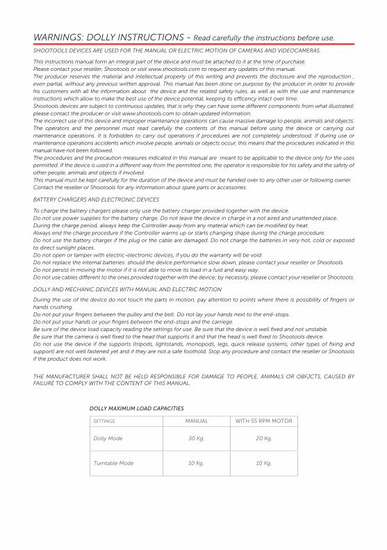
MANUAL WITH 55 RPM MOTORSETTINGS
Dolly Mode 30 Kg.
10 Kg.
20 Kg.
10 Kg.Turntable Mode
DOLLY MAXIMUM LOAD CAPACITIES

I DISPOSITIVI SHOOTOOLS SONO IMPIEGATI PER LA MOVIMENTAZIONE MANUALE O ELETTRICA DI FOTOCAMERE E VIDEOCAMERE.
Il presente manuale viene considerato come parte integrante del dispositivo al quale deve essere allegato al momento dell’acquisto.Contattare il rivenditore, Shootools o visionare il sito internet www.shootools.com per richiedere eventuali aggiornamenti del presente manuale. Il costruttore si riserva la proprietà materiale ed intellettuale della presente pubblicazione e ne vieta la divulgazione e la duplicazione, anche parziale, senza preventivo assenso scritto. Questo manuale è stato voluto dal costruttore per fornire al cliente tutte le informazioni sul dispositivo e sulle norme di sicurezza ad esso collegate, nonché le istruzioni d’uso e di manutenzione che permettono di sfruttare al meglio le potenzialità del dispositivo, mantenendone integra l’efficienza nel tempo.I dispositivi Shootools sono soggetti a continui aggiornamenti, per questo possono montare particolari diversi da quelli illustrati, consultare il costruttore o il sito internet: www.shootools.com per avere eventuali informazioni aggiornate.L’uso scorretto di questo dispositivo ed operazioni di manutenzione improprie comportano pericoli che possono causare seri danni a persone, animali e cose. Gli operatori e le persone addette devono leggere attentamente tutto il contenuto di questo manuale prima di usare il dispositivo o di eseguire operazioni di manutenzione. E’ vietato procedere alla realizzazione di operazioni delle quali non si sono capite le modalità.Se durante l’uso e la manutenzione si verificano incidenti che coinvolgono persone, animali o cose, significa che non sono state rispettate tutte le modalità indicate in questo manuale. Le procedure e precauzioni contenute in questo manuale si intendono applicabili al dispositivo solo per gli usi consentiti.Se il dispositivo viene usato in modo diverso dal consentito, l’operatore è responsabile della sicurezza sua e delle persone, animali e cose eventualmente coinvolte. Il manuale deve essere conservato con cura per tutta la vita del dispositivo Shootools e deve essere trasferito a qualsiasi altro utente o successivo proprietario. Consultare il rivenditore o Shootools per ogni necessità di informazione, ricambi o accessori.
CARICABATTERIE E DISPOSITIVI ELETTRONICI
Per la carica degli accumulatori utilizzare solo il caricabatterie fornito in dotazione con il dispositivo. Non utilizzare alimentatori per la carica delle batterie. Non lasciare il dispositivo in carica in un ambiente non ventilato e non custodito. Durante la carica tenere sempre il Controller lontano da qualsiasi materiale che possa essere alterato dal calore.Terminare sempre il processo di carica se il Controller si riscalda troppo o inizia a deformarsi durante il procedimento di carica.Non utilizzare il caricabatterie se la presa o il cavo sono danneggiati. Non caricare mai le batterie in luoghi estremamente caldi o freddi o esposti alla luce diretta del sole. E’ assolutamente vietato aprire o manomettere i dispositivi elettrici-elettronici, pena la decadenza della garanzia.Non sostituire le batterie interne, se le prestazioni del dispositivo diminuissero, contattare il rivenditore o Shootools.Non insistere nella movimentazione se il motore non riesce a movimentare il carico in modo fluido ed agevole.Non utilizzare cavi diversi da quelli forniti con il dispositivo, in caso di necessità contattare il rivenditore o Shootools.
SLIDER – DOLLY e DISPOSITIVI MECCANICI A MOVIMENTAZIONE MANUALE ED ELETTRICA
Durante l’utilizzo del dispositivo non toccare le parti in movimento, fare attenzione ai potenziali punti di schiacciamento delle dita e delle mani. Non inserire le dita tra puleggia e cinghia. Non appoggiare le mani in prossimità dei finecorsa. Non interporre le mani o le dita tra finecorsa e carrello. Accertarsi della portata del dispositivo nella configurazione di utilizzo.Accertarsi che il dispositivo sia ben fissato e non traballante. Accertarsi che la videocamera/fotocamera sia ben fissata alla testa che la sostiene e che quest’ultima sia ben fissata al dispositivo Shootools. Non utilizzare il dispositivo se i supporti utilizzati (cavalletti, stativi, monopiedi, piedini, sganci rapidi, altri tipi di fissaggio e sostegno) non risultano ben ancorati e se non forniscono una sicura base d’appoggio. Interrompere sempre qualsiasi processo e rivolgersi al rivenditore o a Shootools, se il prodotto funziona male.
IL COSTRUTTORE DECLINA OGNI RESPONSABILITA’ PER EVENTUALI DANNI A PERSONE, ANIMALI O COSE, CAUSATI DALLA NON OSSERVANZA DI QUANTO RIPORTATO NEL PRESENTE MANUALE.
AVVERTENZE LIBRETTO DOLLY - Prima dell’uso leggere attentamente le istruzioni.
MANUALE CON MOTORE 55 RPMCONFIGURAZIONE
Modalità Dolly 30 Kg.
10 Kg.
20 Kg.
10 Kg.Modalità Turntable
PORTATE MASSIME DOLLY

5
CONTENTS
SOMMARIO
Components ........................................................................................................................................ page 6
Componenti ....................................................................................................................................... pag. 6
Dolly assemblly .................................................................................................................................... page 7
Assemblaggio Dolly .......................................................................................................................... pag. 7
Manual or motorized operation ...................................................................................................... page 7
Funzionamento manuale o motorizzato ..................................................................................... pag. 7
Linear operation .................................................................................................................................. page 8
Funzionamento rettilineo ................................................................................................................ pag. 8
Circular operation ............................................................................................................................... page 9
Funzionamento circolare ................................................................................................................ pag. 9
Turntable operation ............................................................................................................................ page 10
Funzionamento turntable ............................................................................................................... pag. 10
Controller Motion Plus and Battery charger.................................................................................. page 11
Controller Motion Plus e Carica batterie ..................................................................................... pag. 11
Controller Motion Plus - Instruction .............................................................................................. page 12
Controller Motion Plus - Istruzioni ............................................................................................... pag. 12
Sliding .................................................................................................................................................... page 13
Carrellata ............................................................................................................................................. pag. 13
Time Lapse............................................................................................................................................. page 15
Time Lapse........................................................................................................................................... pag. 15
Stop Motion .......................................................................................................................................... page 17
Stop Motion ....................................................................................................................................... pag. 17
6
COMPONENTS
COMPONENTI
45 51 28 57
7
7
666
9
9
1212 12 12 10 10
11
13
14
15
3
16
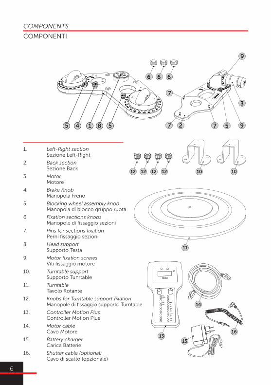
1. Left-Right section Sezione Left-Right
2. Back section Sezione Back
3. Motor Motore
4. Brake Knob Manopola Freno
5. Blocking wheel assembly knob Manopola di blocco gruppo ruota
6. Fixation sections knobs Manopole di fissaggio sezioni
7. Pins for sections fixation Perni fissaggio sezioni
8. Head support Supporto Testa
9. Motor fixation screws Viti fissaggio motore
10. Turntable support Supporto Tunrtable
11. Turntable Tavolo Rotante
12. Knobs for Turntable support fixation Manopole di fissaggio supporto Turntable
13. Controller Motion Plus Controller Motion Plus
14. Motor cable Cavo Motore
15. Battery charger Carica Batterie
16. Shutter cable (optional) Cavo di scatto (opzionale)

7
7
66
7
1
2
7
6
MOTORIZED VERSION: lower the motor, rotating it clockwise, so that the components between motor and wheel are coupled.
MOTORIZZATO: abbassare il motore, ruotandolo in senso orario, in modo che gli ingranaggi tra motore e ruota siano accoppiati.
MANUAL VERSION: lift the motor, rotating it counterclockwise until the complete separation of the motor and the wheel mechanisms.The motor resistance during lifting and lowering is adjusted by the tightening of the 3 screws (9); tighten or loosen the screws to increase or decrease the resistance.
MANUALE: sollevare il motore, ruotandolo in senso antiorario, fino al completo disaccoppiamento tra l’ingranaggio del motore e l’ingranaggio della ruota.La resistenza del motore al sollevamento e abbassamento è regolata dal serraggio delle 3 viti (9), eventualmente stringere o allentare le viti per aumentare o diminuire la resistenza.
DOLLY ASSEMBLLY
MANUAL OR MOTORIZED OPERATION
ASSEMBLAGGIO DOLLY
FUNZIONAMENTO MANUALE O MOTORIZZATO
Put the two sections one upon the other (1 and 2), screw the knobs (6) to the pins (7).
Sovrapporre le due sezioni (1 e 2), avvitare le manopole (6) ai perni (7).
9 9
9
9 9
9
MANUAL MANUALE
MOTORIZED MOTORIZZATO

8
LINEAR OPERATION
FUNZIONAMENTO LINEARE
7
667
1
2
7
6
For each wheel assembly: loosen the knob (5), place the wheel on the 0 on the measuring scale and tighten the knob (5).
Per ogni gruppo ruota: allentare la manopola (5), posizionare la ruota sullo 0 della scala graduata, stringere la manopola (5).
7
6
7
6
6
7
1
2
4
5

9
CIRCULAR OPERATION
FUNZIONAMENTO CIRCOLARE
For each wheel assembly: loosen the knob (5), set the wheel until the rotation axis (wheel pivot) aims the subject; tighten the knob.
Per ogni gruppo ruota: allentare la manopola (5), posizionare la ruota affinché il proprio asse di rotazione punti il soggetto, stringere la manopola (5).
SUBJECT
5 5

10
TURNTABLE OPERATION
FUNZIONAMENTO TURNTABLE
Camera Dolly 360 is the only device in the world which can also turn into turntable.
Il Camera Dolly 360 è l’unico dispositivo al mondo a trasformarsi anche in tavolo rotante.
Place the supports for turntable (10) in the two non-motorized wheel assemblies and fix them with the dedicated knobs (12).
Posizionare i supporti per turntable (10), nei due gruppi ruota non motorizzati e fissarli con le apposite manopole (12).
For each wheel assembly: loosen the knob (5), place the wheel on the reference nick “turntable”, tigthen the knob (5).
Per ogni gruppo ruota: allentare la manopola (5), posizionare la ruota sulla tacca di riferimento “tavolo rotante”, stringere la manopola (5).
Place the turntable upon the upturned Dolly, making the wheel match with the track under the table.
Posizionare il tavolo rotante sopra il Dolly capovolto, facendo combaciare le ruote con il solco presente sotto il tavolo.
1012 1012 1212
5
11

11
CONTROLLER ONE INSTRUCTIONS | ISTRUZIONI 10
1. Time Lapse Mode Modalità Time Lapse
2. Sliding mode Modalità carrellata
3. On-O� On-O�
4. Battery charge indicator Indicatore batteria scarica
5. Battery charger connector Connettore carica batteria
6. Rotating encoder E1 Encoder rotativo E1
7. Rotating encoder E2 Encoder rotativo E2
8. Shutter cable connector Connettore cavo di scatto
9. Motor cable connector Connettore cavo motore
10. Motor cable Cavo motore
11. Shutter cable (optional) Cavo di scatto (optional)
12. Battery charger Carica batteria
If the accumulators are completely charged, bat-tery life may be of more than 48 hours in Time -Lapse mode and more than 1800 sliding tracks . These values may vary depending on the external temperature and on the load which has to be mo-ved.
When the remaining charge is about 10%, the red led on the display will start �ashing.
BATTERY CHARGER INSTRUCTIONS
1) Insert the battery charger into the AC outlet (100-240 Vac)
2) Be sure that the cells selector is arranged on 10.
3) Select the charging current between 500 and 1000 mA. With 500 mA the batteries re-charge in about 3 hours, with 1000 mA the batteries re-
eht Am 005 tceles uoy fI .ruoh 1 tuoba ni egrahcbatteries will have a longer duration.
4) Connect the battery charger to the Controller.
5) The battery charger LED turns out RED.
Press the button “Discharge” if you want to di -scharge the batteries (this operation is optional for a normal charge): the LED turns to YELLOW; if you press the button “Discharge” during the discharge stage, the battery charger goes to the charging stage and the LED turns to RED,
At the end of the discharge procedure, the battery charger goes to the charging stage automatically and the LED turns to RED.
6) When the batteries are charged the LED turns to GREEN. If the charging procedure takes more than 6 hours the battery charger changes into “Trickle Charge” automatically, in order to gua -rantee the user’s safety.
7) Disconnect the battery charger from the con -troller and from AC outlet.
Una carica completa degli accumulatori per -mette un’ autonomia di oltre 48 ore per la mo -dalità TimeLapse e oltre 1800 carrellate . Tali valori possono variare in base alla temperatu -ra esterna ed al carico movimentato.Quando la carica residua è di c.a. il 10%, Il led di colore rosso presente sul display, inizierà a lampeggiare.RICARICA:1) Collegare il carica batterie alla rete elettrica 100-240 Vac.2) Accertarsi che il selettore delle celle sia po -sizionato su 10.3) Selezionare la corrente di carica tra 500 e 1000 mA, con 500 mA le batterie si ricaricano in c.a. 3 ore, con 1000 mA le batterie si ricari -cano in c.a. 1 ora.Selezionando 500 mA le batterie avranno una vita più lunga.4) Collegare il carica batterie al Controller.5) Il LED del carica batterie diventa ROSSO.Premere il tasto “Discharge” se si vogliono sca -ricare le batterie (operazione non obbligatoria per la normale carica), in questo caso il LED diventa GIALLO, premendo il tasto “Dischar -ge” durante la fase di scarica, il carica batterie passa alla fase di carica, il LED diventa ROSSO.
-terie passa in automatico alla fase di carica, il LED diventa ROSSO.6) Quando le batterie sono cariche il LED di -venta VERDE. Se il processo di carica dura più di 6 ore, il carica batterie commuta automati -camente in “Trickle Charge” per garantire la sicurezza dell’utente.7) Disconnettere il carica batterie dal Control -ler e poi dalla rete elettrica.
BATTERY CHARGER / CARICA BATTERIE
1
3
2 4
85
76
9
10
11
12
CONTROLLER MOTION PLUS
CARICA BATTERIE
CONTROLLER MOTION PLUS
BATTERY CHARGER
Una carica completa degli accumulatori permette un’autonomia di oltre 48 ore per lamodalità TimeLapse e oltre 1800 carrellate. Tali valori possono variare in base alla temperatura esterna ed al carico movimentato. Quando la carica residua è di c.a. il 10%, Il led di colore rosso presente sul display, inizierà a lampeggiare.
CONTROLLER ONE INSTRUCTIONS | ISTRUZIONI 10
1. Time Lapse Mode Modalità Time Lapse
2. Sliding mode Modalità carrellata
3. On-O� On-O�
4. Battery charge indicator Indicatore batteria scarica
5. Battery charger connector Connettore carica batteria
6. Rotating encoder E1 Encoder rotativo E1
7. Rotating encoder E2 Encoder rotativo E2
8. Shutter cable connector Connettore cavo di scatto
9. Motor cable connector Connettore cavo motore
10. Motor cable Cavo motore
11. Shutter cable (optional) Cavo di scatto (optional)
12. Battery charger Carica batteria
If the accumulators are completely charged, bat-tery life may be of more than 48 hours in Time -Lapse mode and more than 1800 sliding tracks . These values may vary depending on the external temperature and on the load which has to be mo-ved.
When the remaining charge is about 10%, the red led on the display will start �ashing.
BATTERY CHARGER INSTRUCTIONS
1) Insert the battery charger into the AC outlet (100-240 Vac)
2) Be sure that the cells selector is arranged on 10.
3) Select the charging current between 500 and 1000 mA. With 500 mA the batteries re-charge in about 3 hours, with 1000 mA the batteries re-
eht Am 005 tceles uoy fI .ruoh 1 tuoba ni egrahcbatteries will have a longer duration.
4) Connect the battery charger to the Controller.
5) The battery charger LED turns out RED.
Press the button “Discharge” if you want to di -scharge the batteries (this operation is optional for a normal charge): the LED turns to YELLOW; if you press the button “Discharge” during the discharge stage, the battery charger goes to the charging stage and the LED turns to RED,
At the end of the discharge procedure, the battery charger goes to the charging stage automatically and the LED turns to RED.
6) When the batteries are charged the LED turns to GREEN. If the charging procedure takes more than 6 hours the battery charger changes into “Trickle Charge” automatically, in order to gua -rantee the user’s safety.
7) Disconnect the battery charger from the con -troller and from AC outlet.
Una carica completa degli accumulatori per -mette un’ autonomia di oltre 48 ore per la mo -dalità TimeLapse e oltre 1800 carrellate . Tali valori possono variare in base alla temperatu -ra esterna ed al carico movimentato.Quando la carica residua è di c.a. il 10%, Il led di colore rosso presente sul display, inizierà a lampeggiare.RICARICA:1) Collegare il carica batterie alla rete elettrica 100-240 Vac.2) Accertarsi che il selettore delle celle sia po -sizionato su 10.3) Selezionare la corrente di carica tra 500 e 1000 mA, con 500 mA le batterie si ricaricano in c.a. 3 ore, con 1000 mA le batterie si ricari -cano in c.a. 1 ora.Selezionando 500 mA le batterie avranno una vita più lunga.4) Collegare il carica batterie al Controller.5) Il LED del carica batterie diventa ROSSO.Premere il tasto “Discharge” se si vogliono sca -ricare le batterie (operazione non obbligatoria per la normale carica), in questo caso il LED diventa GIALLO, premendo il tasto “Dischar -ge” durante la fase di scarica, il carica batterie passa alla fase di carica, il LED diventa ROSSO.
-terie passa in automatico alla fase di carica, il LED diventa ROSSO.6) Quando le batterie sono cariche il LED di -venta VERDE. Se il processo di carica dura più di 6 ore, il carica batterie commuta automati -camente in “Trickle Charge” per garantire la sicurezza dell’utente.7) Disconnettere il carica batterie dal Control -ler e poi dalla rete elettrica.
BATTERY CHARGER / CARICA BATTERIE
1
3
2 4
85
76
9
10
11
12
If the accumulators are completely charged, batterylife may be of more than 48 hours in Time-Lapse mode and more than 1800 sliding tracks.These values may vary depending on the external temperature and on the load which has to be moved.When the remaining charge is about 10%, the red led on the display will start flashing.

12
CONTROLLER MOTION PLUS-Instructions
CONTROLLER MOTION PLUS-Istruzioni
Connect the related cable between Controller and motor.
Connettere il cavo in dotazione, tra Controller e motore.
1
Switch the controller on through the ON-OFF but -ton: E1 and E2 encoders start �ashing green light waiting that one of the two is pressed, E1 for time lapse, E2 for sliding.
Accendere il controller attraverso l’interrutto -re ON‐OFF: gli encoder E1 ed E2 iniziano a lam -peggiare con illuminazione verde in attesa che uno dei due venga premuto, E1 per time lapse e stop motion, E2 per carrellata.
2
SLIDING following a seguire
E2
TIME LAPSE from pag. 5
a pag. 5
E1
CONTROLLER ONE INSTRUCTIONS / ISTRUZIONI CONTROLLER ONE
11 CONTROLLER ONE INSTRUCTIONS | ISTRUZIONI
Connettere il cavo in dotazione, tra Controller e motore.
Accendere il controller attraverso l’interruttore ON-OFF: gli encoder E1 ed E2 iniziano a lampeggiare con illuminazione verde in attesa che uno dei due venga premuto, E1 per time lapse e stop motion, E2 per carrellata.
Connect the related cable between Controller and motor.
Switch the controller on through the ON-OFF button: E1 and E2 encoders start flashing green light waiting that one of the two is pressed, E1 for time lapse, E2 for sliding.
1.
2.

13
SLIDING
LEGENDA - KEY PROCEDURA - PROCEDURE
CARRELLATA
Nella modalità Carrellata la movimentazione dei dispositivi Shootools può avvenire in real time (variazione della velocità e della direzione mentre il dispositivo è in movimento) o tramite preimpostazione della velocità e della direzione.
In Sliding track mode, the devices motion can take place in real time (variation of speed and direction whereas the device is moving) or through pre-setting of speed and direction.
SLIDING / CARRELLATA
Press E2 encoder: the Sliding led lights up and E2 encoder lighting becomes steady green.
Premere E2: si accende il led SLIDING e l’illuminazione di E2 diventa verde fissa.
1
Turn E2 encoder while the motor is running in order to change the shift speed and direction.
Ruotare E2 mentre il motore è in movimentazioneper modificare la velocità e la direzione di spostamento
4
Press E2 encoder: the light becomes steady green and the motor stops. Go back to point 1.
Premere E2, l’illuminazione diventa verdefissa, il motore si ferma, si ritorna al punto 1.
5
E2 E1
Turn E2 encoder in order to select the movement speed and direction; speed is expressed in relative values: from 0 to -99 for one movement direction, from 0 to 99 for the other one. Please note that, until E2 encoder is green the motor does not rotate.
Ruotare E2 per selezionare la velocità e la direzione di spostamento; la velocità è espressa in valori relativi: da 1 a -99 per una direzione di spostamento e da -1 a -99 per l’altra. Da notare che fino a quando E2 è verde il motore non ruota.
2
E2 E1
E2 E1
E2 E1
CONTROLLER ONE SLIDING | CARRELLATA 12
Press E2 once, twice or three times depending on the wanted mode: Sync/Loop/No stop. The motor will start 1 second after the last push.
Premere E2 una, due o tre volte in base alla modalità desiderata: Sync/Loop/No Stop. Il motore partirà circa 1 secondo dopo l’ultima pressione.
3
E2 E1
SYNC
E2 E2
LOOP
E2
NO STOP The Sync/Loop/No Stop modes are better explained in the following page.
Le modalità Sync/Loop/No stop sono approfondite alla pagina successiva.
In Sliding track mode, the devices motion can take place in real time (variation of speed and direction whereas the device is moving) or through pre-setting of speed and direction.
Nella modalità Carrellata la movimentazione dei dispositivi Shootools può avvenire in real time (variazio -ne della velocità e della direzione mentre il dispositivo è in movimento) o tramite preimpostazione della velocità e della direzione.

14
SLIDING
SYNC METHOD - MODALITÀ SYNC
CARRELLATA
SYNC
E2
E2
LOOP
E2
NO STOP
x1 blink
START Rec STOP
ENDLESSSTART Rec
x2 blink
ENDLESSSTART Rec
x3 blink
Premendo una volta E2, la registrazione video della DSLR avviene in sincronismo con lo start e lo stop del dispositivo Shootools: avviando il dispositivo si avvia automaticamente la registrazione video, quando il dispositivo si ferma, si ferma automaticamente anche la registrazione video*.
Premendo due volte E2, si avvia il movimento e la registrazione video, all’intervento di un fine corsa (nei dispositivi Shootools che ne sono dotati), il dispositivo inverte la direzione di marcia, ripercorrendo il tragitto poc’anzi eseguito alla medesima velocità, in un loop continuo che termina alla pressione di E2, pressione che ferma anche la registrazione video.
Premendo tre volte E2, si avvia il movimento e la registrazione video, all’intervento di un fine corsa (nei dispositivi Shootools che ne sono dotati), il dispositivo si ferma ma la registrazione video continua fino alla pressione di E2.
If you press E2 three times, the motion and the video recording start when an end-stop occurs (in the Shootools devices which have end-stops), the device stops but the video recording goes on until you press E2.
If you press E2 twice, the motion and the video recording start when an end-stop occurs (in the Shootools devices which have end-stops) the device detours and goes through the way it has just run at the same speed, in a continuous loop which ends when you press E2; this push also stops the video recording.
If you press E2 once, the DSLR video recording takes place in synchronism with the Shootools device START and STOP; as you start the device, the video recording starts automatically, when the device stops, the video recording stops automatically, too.
Accertarsi che eventuali freni siano allentati, movimentare elettricamente un dispositivo frenato danneggerà seriamente il motore ed il controller.
*La sincronizzazione tra il movimento del dispositivo Shootools e lo start e stop della registrazione video della DSLR, avviene attraverso i shutter cable Shootools (se il firmware della DSLR supporta lo start e stop della registrazione video tramite il cavo di scatto, ad esempio per le Canon utilizzare magic lantern o simili) o attraverso video trigger accessori.
Be sure that brakes are loosen, if you electrically move a braked device the motor and the controller will be seriously damaged.
*The synchronism between the Shootools device motion and the DSLR video recording start and stop actions takes place thanks to the Shootools shutter cables (if the DSLR firmware is able to support the video recording start and stop through a shutter cable: for instance, for Canon videocameras you have to use “Magic Lantern” or similar) or video trigger accessories.

15
TIME LAPSE
TIME LAPSE
Nella modalità time lapse la movimentazione dei dispositivi Shootools è del tipo shoot – move – shoot e lo scatto della fotocamera è sincronizzato, (attraverso il cavo opzionale compatibile con le più diffuse fotocamere) è possibile impostare lo spazio di spostamento, la direzione e la durata della pausa tra uno scatto ed il successivo.
In time lapse mode the movement of Shootools devices is shoot – move –shoot and the photocamera shoot is synchronized (using an optional cable which fits with the most common photocameras); it is possible to set the space shifting, the direction and the pause duration between one shot and the following.
Turn E1 encoder in order to select the shift and the direction. The shift is expressed in relative values: from 0 to -99 for one direction, from 0 to 99 for the other one.
Ruotare E1 per selezionare lo spostamento e la direzione, lo spostamento è espresso in valori relativi: da 0 a 99 per una direzione e da 0 a 99 per l’altra.
2
SHIFT SETTING - IMPOSTAZIONE DELLO SPOSTAMENTO
PAUSE SETTING - IMPOSTAZIONE DELLA PAUSA
KEY - LEGENDA
KEY - LEGENDA
Press E1 encoder: the TIME LAPSE led lights up and E1 encoder light becomes steady green.
Premere E1: si accende il led TIME LAPSE e l’illuminazione di E1 diventa fissa.
1
E2 E1
E2 E1
Examples30” pause:
1’ 45” pause:
- set “s” turning E2 encoder- set “30” turning E2 encoder
- set “s” turning E2 encoder- set “45” turning E1 encoder- set “m” turning E2- set “1” turning E1
EsempiPer una pausa di 30”:
Per una pausa di 1’ e 45”:
- impostare “s” ruotando E2- impostare “30” ruotando E 1
- impostare “s” ruotando E2- impostare “45” ruotando E 1- impostare “m” ruotando E2- impostare “1” ruotando E 1
Turn E2 encoder to set seconds, minutes and hours; the selection is visible from the lighting of the dedicated led “s-m-h”.
Turn E1 encoder in order to set seconds, minutes and hours (from 0 to 59 for the seconds and the minutes setting, from 0 to 99 for the hours setting).
Ruotare E2 per scegliere tra secondi, minuti e ore, la scelta è visibile dall’accensione del relativo led “s-m-h”.
Ruotare E1 per impostare il valore dei secondi, minuti e ore (da 0 a 59 per secondi e minuti, da 0 a 99 per le ore).
3
E2 E1
Press E2 once, twice or three times depending on the wanted mode: Sync /Loop/No Stop. The motor will start about 1 second after the last push.
Premere E2 una, due o tre volte in base alla modalitàdesiderata: Sync/Loop/No Stop. Il motore partiràcirca 1 secondo dopo l’ultima pressione.
4
E2 E1
SYNC
E2 E2
LOOP
E2
NO STOPThe Sync/Loop/No Stop modes are better explained in thefollowing page.
Le modalità Sync/Loop/No stop sono approfondite alla paginasuccessiva.

16 TIME LAPSE | TIME LAPSE CONTROLLER ONE15
NOTES ON USE
The minimum speed at which the carriage starts running depends on di�erent standards: equipment weight, belt tension, battery charge level, slider incli -nation compared to the horizontal plane. Therefore it is very normal that the carriage starts moving within values which range from 1 to 10. Please note that, when the speed is at the minimum values, the motor motion might not be �uid: this happens because the operation is being done next to the stall torque. It is suggested to do some tests before starting using the device.
NOTE SULL’UTILIZZO
La minima velocità con la quale il carrello inizia a muoversi è funzione di vari parametri: peso dell’at -trezzatura, tensione della cinghia, stato di carica delle batterie, inclinazione dello slider rispetto al piano orizzontale. E’ quindi normale che il carrello inizi a muoversi a valori che oscillano tra 1 e 10, da notare che alla minima velocità il movimento
perché si sta operando in prossimità della coppia di stallo. Si consiglia di eseguire delle prove prima dell’utilizzo.
SYNC
E2
E2
LOOP
Be sure that brakes are loosen, if you electrically move a braked device the motor and the controller will be seriously damaged.
Accertarsi che eventuali freni siano allentati, movimentare elettricamente un dispositivo frenato danneg -gerà seriamente il motore ed il controller.
E2
NO STOP
x1 blink
START Time Lapse STOP
ENDLESSSTART Time Lapse
x2 blink
ENDLESSSTART Time Lapse
x3 blink
Accertarsi che eventuali freni siano allentati, movimentare elettricamente un dispositivo frenato danneggerà seriamente il motore ed il controller.
Be sure that brakes are loosen, if you electrically move a braked device the motor and the controller will be seriously damaged.
SYNC METHOD - MODALITÀ SYNC
Premendo una volta E2, il Time Lapse avviene in sincronismo con lo start e lo stop del dispositivo Shootools: avviando il dispositivo si avvia automaticamente il Time Lapse, quando il dispositivo si ferma, si ferma automaticamente anche il Time Lapse*.
Premendo due volte E2, si avvia il movimento e il Time Lapse, all’intervento di un fine corsa (nei dispositivi Shootools che ne sono dotati), il dispositivo inverte la direzione di marcia, ripercorrendo il tragitto poc’anzi eseguito alla medesima velocità, in un loop continuo che termina alla pressione di E2, pressione che ferma anche il Time Lapse.
Premendo tre volte E2, si avvia il movimento di Time Lapse, all’intervento di un fine corsa (nei dispositivi Shootools che ne sono dotati), il dispositivo si ferma ma il Time Lapse continua fino alla pressione di E2.
Le varie modalità d’uso del Controller Motion Plus possono variare in base al prodotto accoppiato: Slider, Dolly, Turntable, ecc.
If you press E2 once, the Time Lapse takes place in synchronism with the Shootools device START and STOP; as you start the device, the Time Lapse starts automatically, when the device stops, the Time Lapse* stops automatically, too.
The different ways of use of the Controller Motion Plus can change depending on the product which is combined: Slider, Dolly, Turntable, etc.
If you press E2 twice, the motion and the Time Lapse start when an end-stop occurs (in the Shootools devices which have end-stops) the device detours and goes through the way it has just run at the same speed, in a continuous loop which ends when you press E2; this push also stops the Time Lapse.
If you press E2 three times, Time Lapse movement starts when an end-stop occurs (in the Shootools devices which have end-stops), the device stops but the Time Lapse goes on until you press E2.
La minima velocità con la quale il carrello inizia amuoversi è funzione di vari parametri: peso dell’attrezzatura, tensione della cinghia, stato di carica delle batterie, inclinazione dello slider rispetto al piano orizzontale. E’ quindi normale che il carrello inizi a muoversi a valori che oscillano tra 1 e 10, da notare che alla minima velocità il movimento del motore può non essere fluido, questo accade perché si sta operando in prossimità della coppia di stallo. Si consiglia di eseguire delle prove prima dell’utilizzo.
The minimum speed at which the carriage starts running depends on different standards: equipment weight, belt tension, battery charge level, slider inclination compared to the horizontal plane. Therefore it is very normal that the carriage starts moving within values which range from 1 to 10. Please note that, when the speed is at the minimum values, the motor motion might not be fluid: this happens because the operation is being done next to the stall torque. It is suggested to do some tests before starting using the device.
NOTE SULL’UTILIZZONOTES ON USE
TIME LAPSE
TIME LAPSE

17
Nella modalità Stop / Motion la movimentazione dei dispositivi Shootools è del tipo shoot-move-shoot e lo scatto della fotocamera è sincronizzato, (attraverso il cavo opzionale compatibile con le più diffuse fotocamere) con lo spostamento del dispositivo.
In the Stop/Motion mode, the movement of Shootools devices is shoot – move –shoot and the photocamera shoot is synchronized (using an optional cable which fits with the most common photocameras) with the shift of the device.
2
3
1
In the Stop/Motion mode, the movement of Shootools devices is shot – move –shot and the photocamera shot is synchro-nized (using an optional cable which fits with the most common photocameras) with the shift of the device.
Nella modalità Stop / Motion la movimentazione dei dispositivi Shootools è del tipo shot – move – shot e lo scatto della fotocamera è sincronizzato, (attraverso il cavo opzionale compatibile con le più di use fotocamere) con lo spostamento del dispositivo.
E2 E1
E2 E1
E2 E1
STOP MOTION / STOP MOTION
4
5
E2 E1
E2 E1
IMPOSTAZIONE DELLO SPOSTAMENTO - SHIFT SETTING
IMPOSTAZIONE DELLA PAUSA - PAUSE SETTING
LEGENDA -
Premere E1: si accende il led TIME LAPSE el’illuminazione di E1 diventa verde fissa.
KEY
Ruotare E1 per selezionare lo spostamento e la direzione, lo spostamento è espresso in valori relativi: da 0 a 99 per una direzione e da 0 a 99 per l’altra.
Ruotare E2 per scegliere tra secondi, minuti e ore ed impostare le ore. La scelta è visibile dall’accensione del relativo led “s-m-h”.
Ruotare E1 ed impostare 99 ore.
Premere E2 una sola volta, per avviare lo Stop Motion, il controller entra in modalità risparmio energetico.
Per passare al movimento successivo quando si è pronti per fa scattare, Premere E1 e poi E2 senzavariare alcun parametro.
Press E1 encoder: the TIME LAPSE led lights up and E1 encoder light becomes steady green.
Turn E1 encoder in order to select the shift and the
direction. The shift is expressed in relative values: from
0 to -99 for one direction, from 0 to 99 for the other one.
Rotate E2 in order to set seconds, minutes and hours
and set hours. The selection is visible from the lighting
of the dedicated led “s-m-h”.
Rotate E1 to set 99 hours.
Press E2 just once to start the STOP MOTION, the
controller goes into the energy saving mode.
To go to the following movement: when you are ready
to shot, Press E1 and then E2 without changing any
standard.
STOP MOTION
STOP MOTION

18
NOTES
NOTE

19
NOTES
NOTE

VIA GRADO, 4 INT. 5
PAVIA DI UDINE 33050 UD - ITALY
Tel. +39 0432 [email protected]
1.0 Logo
C 0 - M 0 - Y 0 - K 10C 0 - M 100 - Y 100 - K 0
R 0 - G 0 - B 0R 255 - G 0 - B 0
1.1 Logo negativo
1.2 Logo tagline 1.2.1 Logo tagline negativo
Filmmakers Motion Equipment Filmmakers Motion Equipment
1.3 Logo Social
TRADITIONINNOVATION
PASSION