instruction manual - media.bluestonepim.com · select v the display will show no-load voltage when...
TRANSCRIPT

Revision date: 23/09/2014 Page 1 of 40
Instruction manual
Unitor Welding Inverter UWI 500 TP & UWF 102
MMA, ACA, TIG and Wire welding
Revision date: 23/09/2014 Page 2 of 40
CONTENTS SECTION PAGE
1. GENERAL DESCRIPTION 3 2. TECHNICAL DATA 4
3. INSTALLATION 7
4. FRONT PANEL CONTROLS 8
5. STICK ELECTRODE WELDING 10
6. AIR CARBON ARC GOUGING 11
7. TIG WELDING 12
8. WIRE WELDING 13 9. ROUTINE MAINTENANCE 18
10. TROUBLESHOOTING 19
11. ORDERING INFORMATION MACHINES 21
12. ORDERING INFORMATION BASIC ACCESSORIES 22
13. TIG AND W1RE TORCHES WITH SPARES 23
14. WIRING DIAGRAM UWI-500TP 26
15. COMPONENTS AND SPARES UWI-500TP 28
16. COMPONENTS AND SPARES UWF-102 30
17. WIRING DIAGRAM FOR UWF-102 32
18. SAFETY INSTRUCTIONS 33
19. NOTES 37
20. UNITOR HANDBOOK FOR MARITIME WELDERS 39
DO NOT INSTALL, OPERATE OR REPAIR THIS EQUIPMENT WITHOUT READING THIS MANUAL INCLUDING THE SAFETY INSTRUCTIONS
Revision date: 23/09/2014 Page 3 of 40
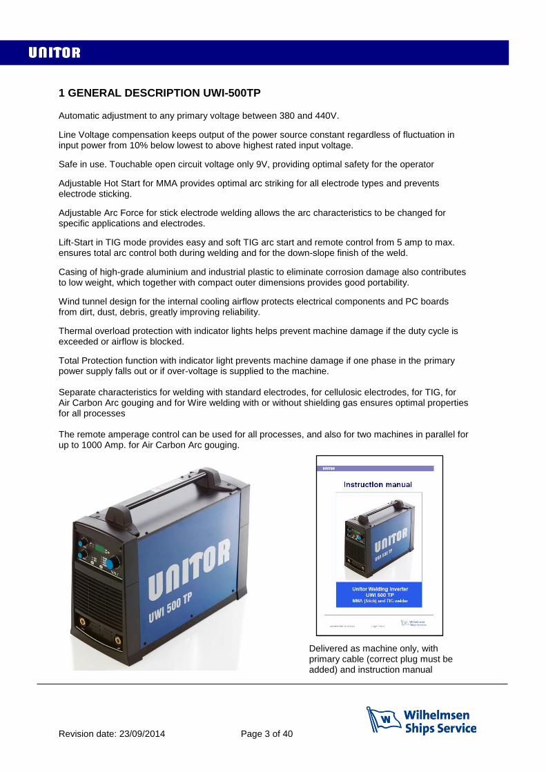
1 GENERAL DESCRIPTION UWI-500TP
Automatic adjustment to any primary voltage between 380 and 440V.
Line Voltage compensation keeps output of the power source constant regardless of fluctuation in input power from 10% below lowest to above highest rated input voltage.
Safe in use. Touchable open circuit voltage only 9V, providing optimal safety for the operator
Adjustable Hot Start for MMA provides optimal arc striking for all electrode types and prevents electrode sticking.
Adjustable Arc Force for stick electrode welding allows the arc characteristics to be changed for specific applications and electrodes.
Lift-Start in TIG mode provides easy and soft TIG arc start and remote control from 5 amp to max. ensures total arc control both during welding and for the down-slope finish of the weld.
Casing of high-grade aluminium and industrial plastic to eliminate corrosion damage also contributes to low weight, which together with compact outer dimensions provides good portability.
Wind tunnel design for the internal cooling airflow protects electrical components and PC boards from dirt, dust, debris, greatly improving reliability.
Thermal overload protection with indicator lights helps prevent machine damage if the duty cycle is exceeded or airflow is blocked.
Total Protection function with indicator light prevents machine damage if one phase in the primary power supply falls out or if over-voltage is supplied to the machine. Separate characteristics for welding with standard electrodes, for cellulosic electrodes, for TIG, for Air Carbon Arc gouging and for Wire welding with or without shielding gas ensures optimal properties for all processes The remote amperage control can be used for all processes, and also for two machines in parallel for up to 1000 Amp. for Air Carbon Arc gouging.
Delivered as machine only, with primary cable (correct plug must be added) and instruction manual
Revision date: 23/09/2014 Page 4 of 40
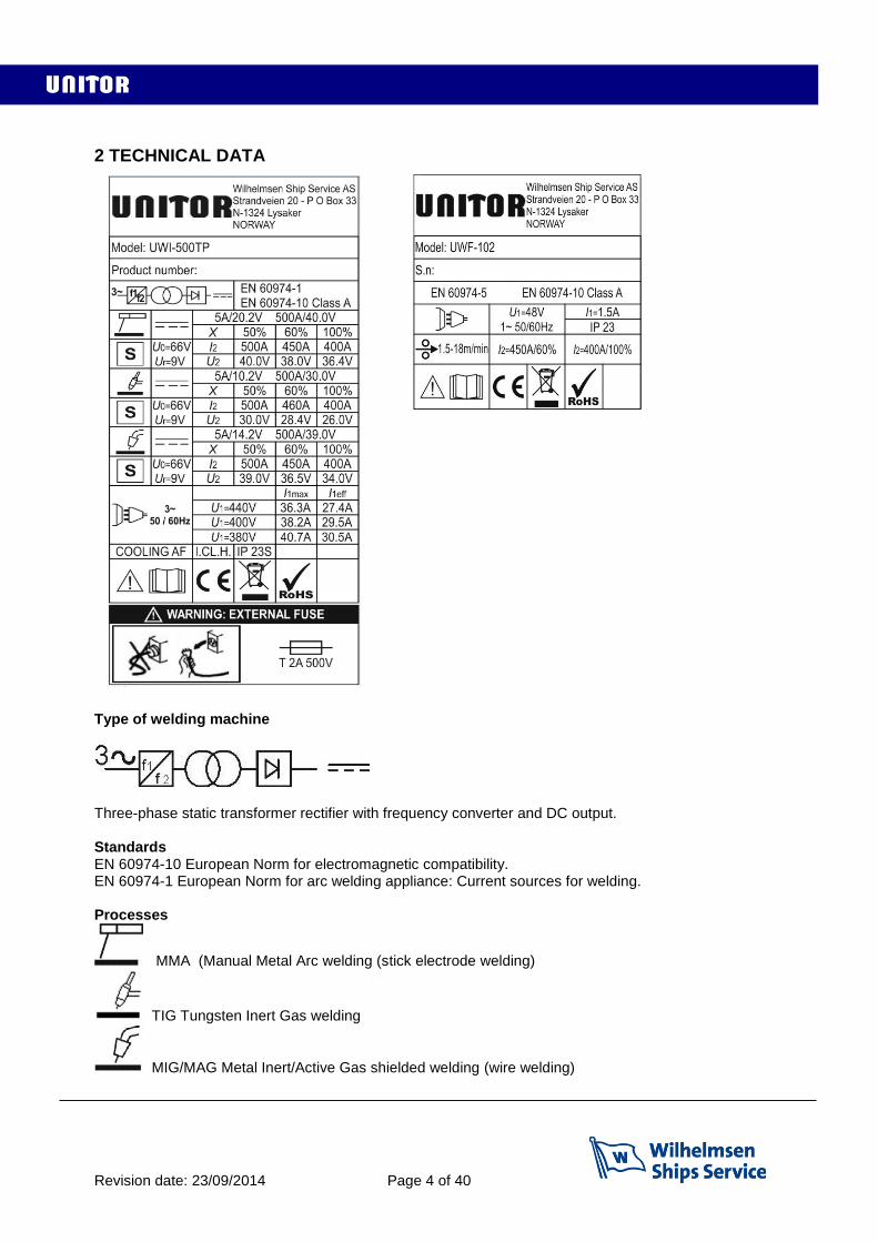
2 TECHNICAL DATA
Type of welding machine
Three-phase static transformer rectifier with frequency converter and DC output. Standards EN 60974-10 European Norm for electromagnetic compatibility. EN 60974-1 European Norm for arc welding appliance: Current sources for welding. Processes
MMA (Manual Metal Arc welding (stick electrode welding)
TIG Tungsten Inert Gas welding
MIG/MAG Metal Inert/Active Gas shielded welding (wire welding)
Revision date: 23/09/2014 Page 5 of 40
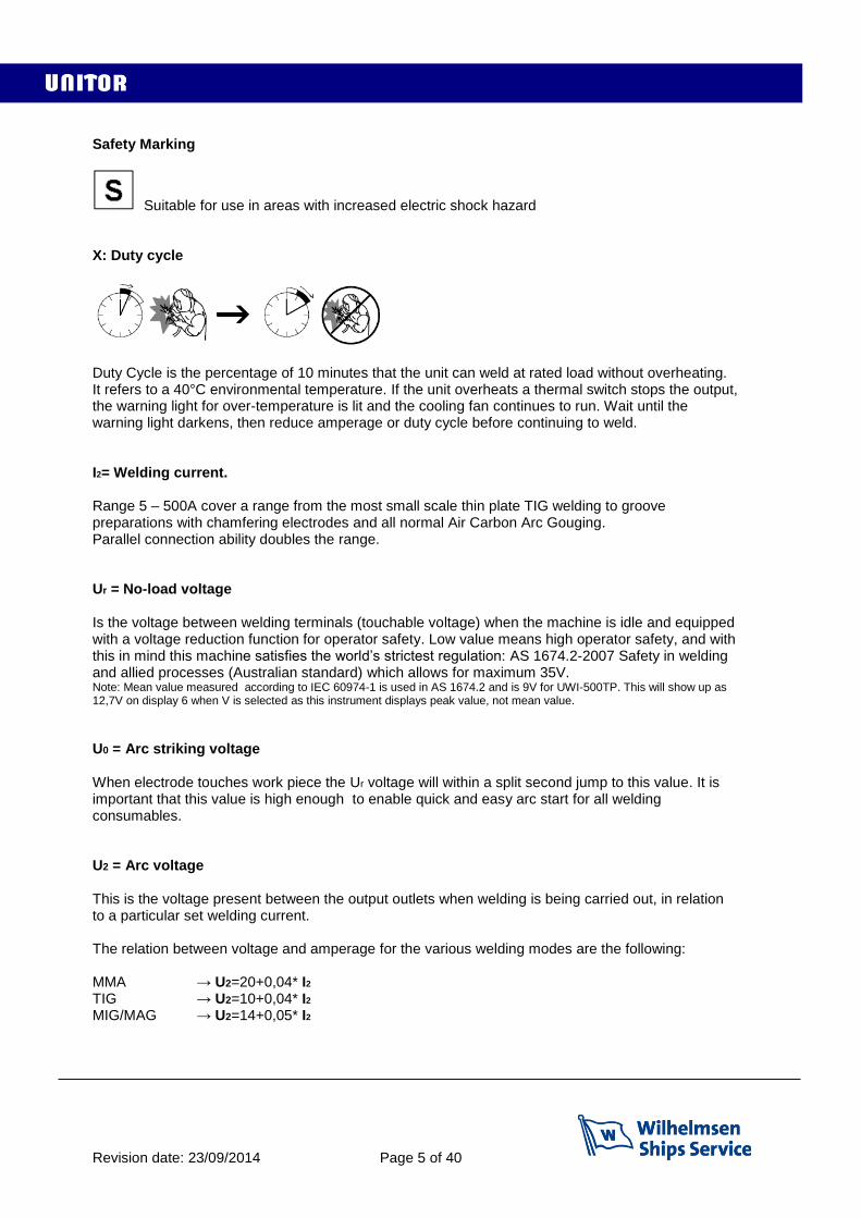
Safety Marking
Suitable for use in areas with increased electric shock hazard X: Duty cycle
Duty Cycle is the percentage of 10 minutes that the unit can weld at rated load without overheating. It refers to a 40°C environmental temperature. If the unit overheats a thermal switch stops the output, the warning light for over-temperature is lit and the cooling fan continues to run. Wait until the warning light darkens, then reduce amperage or duty cycle before continuing to weld. I2= Welding current. Range 5 – 500A cover a range from the most small scale thin plate TIG welding to groove preparations with chamfering electrodes and all normal Air Carbon Arc Gouging. Parallel connection ability doubles the range. Ur = No-load voltage Is the voltage between welding terminals (touchable voltage) when the machine is idle and equipped with a voltage reduction function for operator safety. Low value means high operator safety, and with this in mind this machine satisfies the world’s strictest regulation: AS 1674.2-2007 Safety in welding and allied processes (Australian standard) which allows for maximum 35V. Note: Mean value measured according to IEC 60974-1 is used in AS 1674.2 and is 9V for UWI-500TP. This will show up as 12,7V on display 6 when V is selected as this instrument displays peak value, not mean value.
U0 = Arc striking voltage When electrode touches work piece the Ur voltage will within a split second jump to this value. It is important that this value is high enough to enable quick and easy arc start for all welding consumables. U2 = Arc voltage This is the voltage present between the output outlets when welding is being carried out, in relation to a particular set welding current. The relation between voltage and amperage for the various welding modes are the following: MMA → U2=20+0,04* I2 TIG → U2=10+0,04* I2 MIG/MAG → U2=14+0,05* I2

Revision date: 23/09/2014 Page 6 of 40
Primary connection
U1 = Effective input voltage which must be between 380 and 440V I1max = Maximum value of input current at the corresponding duty cycle. I1eff = Effective value of input current at the corresponding duty cycle. Maximum input power is 26,5 kVA. Power factor 0,85. Duty Cycle 50%
32A slow fuses will be the right fuse size for this machine. NOTE: If two machines are to be used in parallel for up to 1000 amp output each machine needs a separate 32 Amp connection. Cooling COOLING AF= Forced air cooling (with a fan). NOTE: This cooling requires sufficient space to allow free air flow for cooling, a minimum of 50 cm on all sides is recommended, Protection class IP23S= Ingress Protection class. Protection degree of the casing according to EN 60529 2: Protection against object 80mm in length and more than 12mm in diameter 3: Protection from sprayed water at an angle of 60º from vertical S: Valid at standstill. (Can be used outdoors but not in heavy wind and rain) NOTE: Equipment with lower IP class should not be used outdoors. Thermal insulation class I.CL.H= Thermal class of the insulating materials and insulation systems. Class H: resistant up to 180°C. Conformity to the rules of the European Union Mark stating conformity to all safety standards and other standards required for sale
and use within the European Union.
Recast Directive
This mark confirms that the product confirms to the RoHS directive which restricts the use of specific hazardous or restricted substances in electrical and electronic equipment put on the market in the European Union. Restricted substances are:1.Lead (0.1%) 2. Mercury (0.1%) 3. Cadmium (0.01%) 4. Hexavalent chromium (0.1%) 5. Polybrominated biphenyls (0.1%) 6. Polybrominated diphenyl ethers (PBDE) (0.1%)

Revision date: 23/09/2014 Page 7 of 40
3 INSTALLATION
Only qualified personnel should perform this installation. Only personnel that have read and understood this Manual should install and operate this equipment. Machine must only be plugged into a receptacle which is grounded in accordance with valid regulations. Note The power switch should be in the OFF position when installing work cable and electrode cable and when connecting power cord to input power. Dimensions and weight UWI-500 UWF-102 Height : 510mm 440mm Length : 670mm 690mm Width : 290mm 385mm Weight : 47kg 17,4kg Select suitable location UWI 500TP and UWF-102 have IP23S rating. Locate UWI-500TP in a dry location where there is free circulation of clean air into the louvers in the back and out the front of the unit. Ensure minimum 50cm free space on all sides. If free flow of air is hindered the machine will overheat. A location that minimizes the amount of smoke and dirt drawn into the louvers reduces the chance of dirt accumulation that can block air passages and cause overheating. The UWF-102 has no air cooling. Avoid tilting The machine must be placed on a secure, level surface, maximum 15º out of horizontal. Rear panel functions 1: Primary cable. Mount plug and connect to socket with 32A slow fuses 2: On/Off switch 3: When lit the Total Protection function has been activated due to one missing phase in the power supply. Switch machine off, and correct the power supply before continuing. 4: Remote control connection. Note: If remote control is connected it must be activated by selecting remote control on the front panel 5: Power supply transformer fuse, slow, 530mA, 500V 6: Control cable to wire feeder (at the bottom)
1
2
3 4
5
6
Revision date: 23/09/2014 Page 8 of 40
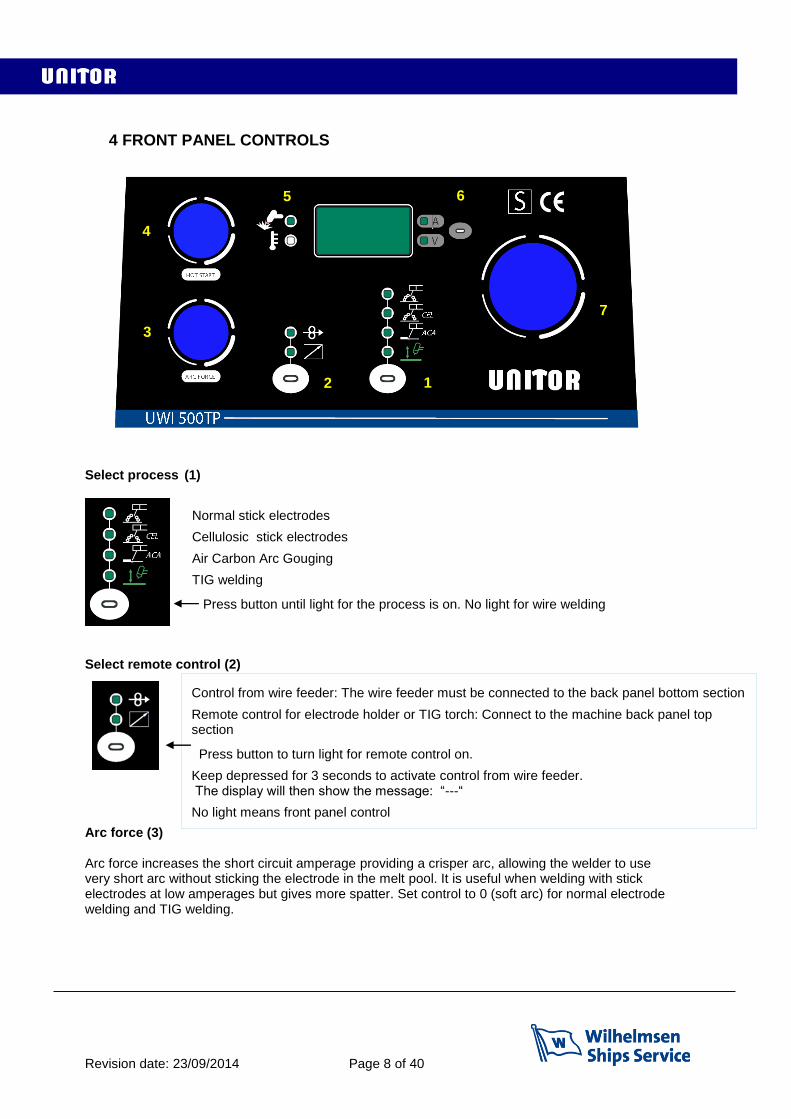
4 FRONT PANEL CONTROLS
Select process (1)
Select remote control (2) Arc force (3) Arc force increases the short circuit amperage providing a crisper arc, allowing the welder to use very short arc without sticking the electrode in the melt pool. It is useful when welding with stick electrodes at low amperages but gives more spatter. Set control to 0 (soft arc) for normal electrode welding and TIG welding.
Normal stick electrodes
Cellulosic stick electrodes
Air Carbon Arc Gouging
TIG welding
Press button until light for the process is on. No light for wire welding
Control from wire feeder: The wire feeder must be connected to the back panel bottom section
Remote control for electrode holder or TIG torch: Connect to the machine back panel top section
Press button to turn light for remote control on.
Keep depressed for 3 seconds to activate control from wire feeder. The display will then show the message: “---“
No light means front panel control
4
3
7
6 5
1 2
Revision date: 23/09/2014 Page 9 of 40
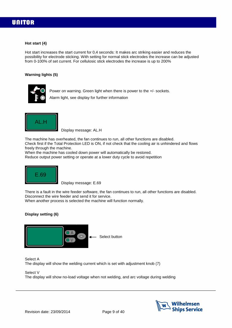
Hot start (4) Hot start increases the start current for 0,4 seconds: It makes arc striking easier and reduces the possibility for electrode sticking. With setting for normal stick electrodes the increase can be adjusted from 0-100% of set current. For cellulosic stick electrodes the increase is up to 200% Warning lights (5)
Display message: AL.H The machine has overheated, the fan continues to run, all other functions are disabled. Check first if the Total Protection LED is ON, if not check that the cooling air is unhindered and flows freely through the machine. When the machine has cooled down power will automatically be restored. Reduce output power setting or operate at a lower duty cycle to avoid repetition
Display message: E.69 There is a fault in the wire feeder software, the fan continues to run, all other functions are disabled. Disconnect the wire feeder and send it for service. When another process is selected the machine will function normally. Display setting (6) Select button Select A The display will show the welding current which is set with adjustment knob (7) Select V The display will show no-load voltage when not welding, and arc voltage during welding
Power on warning. Green light when there is power to the +/- sockets.
Alarm light, see display for further information
AL.H
E.69
Revision date: 23/09/2014 Page 10 of 40
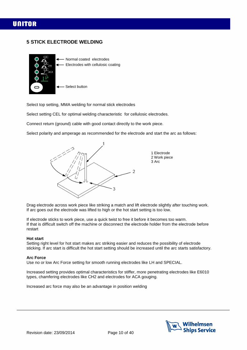
5 STICK ELECTRODE WELDING
Select top setting, MMA welding for normal stick electrodes Select setting CEL for optimal welding characteristic for cellulosic electrodes. Connect return (ground) cable with good contact directly to the work piece. Select polarity and amperage as recommended for the electrode and start the arc as follows: Drag electrode across work piece like striking a match and lift electrode slightly after touching work. If arc goes out the electrode was lifted to high or the hot start setting is too low. If electrode sticks to work piece, use a quick twist to free it before it becomes too warm. If that is difficult switch off the machine or disconnect the electrode holder from the electrode before restart Hot start Setting right level for hot start makes arc striking easier and reduces the possibility of electrode sticking. If arc start is difficult the hot start setting should be increased until the arc starts satisfactory. Arc Force Use no or low Arc Force setting for smooth running electrodes like LH and SPECIAL. Increased setting provides optimal characteristics for stiffer, more penetrating electrodes like E6010 types, chamfering electrodes like CH2 and electrodes for ACA gouging. Increased arc force may also be an advantage in position welding
Normal coated electrodes
Electrodes with cellulosic coating
1 Electrode 2 Work piece 3 Arc
Select button
Revision date: 23/09/2014 Page 11 of 40
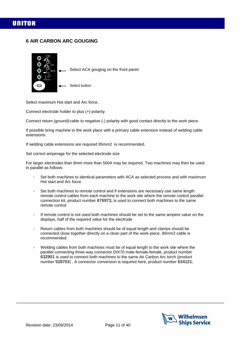
6 AIR CARBON ARC GOUGING
Select ACA gouging on the front panel.
Select maximum Hot start and Arc force. Connect electrode holder to plus (+) polarity. Connect return (ground) cable to negative (-) polarity with good contact directly to the work piece. If possible bring machine to the work place with a primary cable extension instead of welding cable extensions. If welding cable extensions are required 95mm2 is recommended. Set correct amperage for the selected electrode size For larger electrodes than 8mm more than 500A may be required. Two machines may then be used in parallel as follows:
- Set both machines to identical parameters with ACA as selected process and with maximum Hot start and Arc force
- Set both machines to remote control and if extensions are necessary use same length remote control cables from each machine to the work site where the remote control parallel
connection kit, product number 676973, is used to connect both machines to the same remote control
- If remote control is not used both machines should be set to the same ampere value on the displays, half of the required value for the electrode
- Return cables from both machines should be of equal length and clamps should be connected close together directly on a clean part of the work-piece. 95mm2 cable is recommended.
- Welding cables from both machines must be of equal length to the work site where the
parallel connecting three-way connector DIX70 male-female-female, product number
632901 is used to connect both machines to the same Air Carbon Arc torch (product
number 528703) . A connector conversion is required here, product number 634121.
Select button
Revision date: 23/09/2014 Page 12 of 40
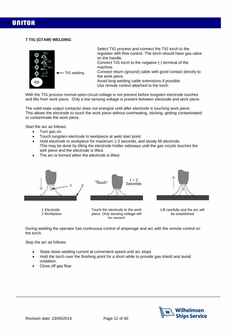
7 TIG (GTAW) WELDING
Select TIG process and connect the TIG torch to the regulator with flow control. The torch should have gas valve on the handle. Connect TIG torch to the negative (-) terminal of the machine. Connect return (ground) cable with good contact directly to the work piece. Avoid long welding cable extensions if possible. Use remote control attached to the torch
With the TIG process normal open-circuit voltage is not present before tungsten electrode touches and lifts from work piece. Only a low sensing voltage is present between electrode and work piece. The solid-state output contactor does not energize until after electrode is touching work piece. This allows the electrode to touch the work piece without overheating, sticking, getting contaminated or contaminate the work piece. Start the arc as follows:
Turn gas on.
Touch tungsten electrode to workpiece at weld start point.
Hold electrode to workpiece for maximum 1-2 seconds, and slowly lift electrode. This may be done by tilting the electrode holder sideways until the gas nozzle touches the wirk piece and the electrode is lifted.
The arc is formed when the electrode is lifted. . During welding the operator has continuous control of amperage and arc with the remote control on the torch. Stop the arc as follows:
Slope down welding current at convenient speed until arc stops
Hold the torch over the finishing point for a short while to provide gas shield and avoid oxidation.
Close off gas flow
1 Electrode 2 Workpiece
Lift carefully and the arc will be established
Touch the electrode to the work piece. Only sensing voltage will
be present
2 Workpiece
TIG welding
Revision date: 23/09/2014 Page 13 of 40
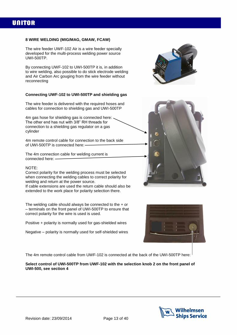
8 WIRE WELDING (MIG/MAG, GMAW, FCAW) The wire feeder UWF-102 Air is a wire feeder specially developed for the multi-process welding power source UWI-500TP. By connecting UWF-102 to UWI-500TP it is, in addition to wire welding, also possible to do stick electrode welding and Air Carbon Arc gouging from the wire feeder without reconnecting Connecting UWF-102 to UWI-500TP and shielding gas The wire feeder is delivered with the required hoses and cables for connection to shielding gas and UWI-500TP 4m gas hose for shielding gas is connected here: The other end has nut with 3/8” RH threads for connection to a shielding gas regulator on a gas cylinder 4m remote control cable for connection to the back side of UWI-500TP is connected here: The 4m connection cable for welding current is connected here: NOTE: Correct polarity for the welding process must be selected when connecting the welding cables to correct polarity for welding and return at the power source. If cable extensions are used the return cable should also be extended to the work place for polarity selection there. The welding cable should always be connected to the + or – terminals on the front panel of UWI-500TP to ensure that correct polarity for the wire is used is used. Positive + polarity is normally used for gas-shielded wires Negative – polarity is normally used for self-shielded wires The 4m remote control cable from UWF-102 is connected at the back of the UWI-500TP here: Select control of UWI-500TP from UWF-102 with the selection knob 2 on the front panel of UWI-500, see section 4
Revision date: 23/09/2014 Page 14 of 40
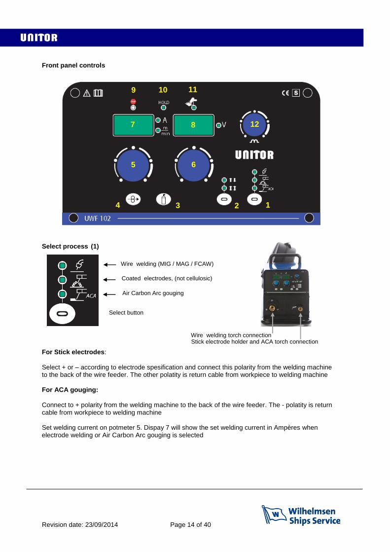
Front panel controls Select process (1) For Stick electrodes: Select + or – according to electrode spesification and connect this polarity from the welding machine to the back of the wire feeder. The other polatity is return cable from workpiece to welding machine For ACA gouging: Connect to + polarity from the welding machine to the back of the wire feeder. The - polatity is return cable from workpiece to welding machine Set welding current on potmeter 5. Dispay 7 will show the set welding current in Ampères when electrode welding or Air Carbon Arc gouging is selected
1 2 3 4
5 6
7 8
9 10 11
12
Coated electrodes, (not cellulosic)
Air Carbon Arc gouging
Select button
Wire welding (MIG / MAG / FCAW)
Wire welding torch connection Stick electrode holder and ACA torch connection

Revision date: 23/09/2014 Page 15 of 40
Select wire welding process Connect proper polarity for the wire from the front of the welding machine to the back of the wire feeder, and the return cable from the work-piece to the welding machine Select trigger function (2) 2-stroke is used for shorter welds, 4-stroke is used for long continuous welds so that the welder does not have to keep the trigger pressed through the whole welding sequence Set shielding gas flow and post gas time (3) Press again for 2 seconds and the letters P.G. will appear on Display 7 and gas post flow in seconds will appear on Display 8. Adjust post flow time with potmeter 6 if required, then press again to store the value. Cold wire feed (4) Set wire feed sped (5) Set wire feed speed on potmeter 5. Dispay 7 will show the set wire speed in m/min when wire welding is selected Set welding voltage (6) Set wire feed speed on potmeter 6. Dispay 8 will show the set voltage when wire welding is selected Adjust inductance (12) When welding with a short arc lower inductance will give crisper arc and easier arc start. The bead will become taller and narrower. More inductance will give a softer arc and flatter wider bead appearance. Too much inductance will give difficult arc starts. Low thermal conductivity materials like stainless steel need more inductance to get acceptable wetting with short arc.
4-stroke function. Press and release trigger to start wire feed and welding, then Press and release trigger to stop wire feed and welding.
2-stroke function. Press trigger to start wire feed and welding, and keep trigger pressed. Release trigger to stop wire feed and welding.
Connect shielding gas from gas cylinder flow regulator to the back of the wire feeder and open for gas. Press and release this button and the gas valve in the wire feeder will open for 15 seconds to allow adjustment of correct flow on the cylinder regulator.
When wire spool is properly inserted and drive rolls closed this button is pressed to feed the wire through to the torch without voltage / welding current present, and without shielding gas flow.

Revision date: 23/09/2014 Page 16 of 40
Warning signals 9: The welding machine has overheated and needs cooling See ch.4:5 10: “HOLD”: The displays 7 and 8 show last real measured values. The light will go out when welding starts again and real values will be shown 11: When lit this light informs that power is available at the wire feeder terminals Display 8 warning messages
Remote control from wire feeder has not been selected on the welding machine, see ch.4:2 When communication between welding machine and wire feeder does not function properly message Err.C0, Err.C11 or Err.C12 will be displayed. The welding machine has overheated and needs cooling. This message will be displayed together with warning light 1. See ch.4:5
Spool box and wire feed compartment UWF 102 wire feeder has a separate spool box outside The wire feed compartment. The spool box is angled slightly upwards for operator ease of use, and facilitates all standard spool sizes. Spool box lid Note: Keep closed when welding, the wire will then be Electrically live. Spool box Shaft for wire spool
Set Gen
Err.Cxx
AL.HEA
Locking stud. Fits corresponding hole in spool and prevents spool from sliding on the shaft
Friction brake adjustment. Correctly set the brake will stop the spool at the instant welding stops to prevent wire from unwinding from the spool, but not hold back so much that smooth wire feeding is prevented
Locking cap for shaft
Wire feed system with drive rolls and adjustment of the drive roll pressure in the wire, see next page.
Revision date: 23/09/2014 Page 17 of 40
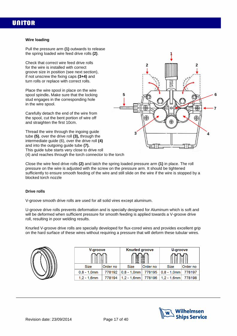
Wire loading Pull the pressure arm (1) outwards to release the spring loaded wire feed drive rolls (2). Check that correct wire feed drive rolls for the wire is installed with correct groove size in position (see next section), if not unscrew the fixing caps (3+4) and turn rolls or replace with correct rolls. Place the wire spool in place on the wire spool spindle. Make sure that the locking stud engages in the corresponding hole in the wire spool. Carefully detach the end of the wire from the spool, cut the bent portion of wire off and straighten the first 10cm. Thread the wire through the ingoing guide tube (5), over the drive roll (3), through the intermediate guide (6), over the drive roll (4) and into the outgoing guide tube (7). This guide tube starts very close to drive roll (4) and reaches through the torch connector to the torch Close the wire feed drive rolls (2) and latch the spring loaded pressure arm (1) in place. The roll pressure on the wire is adjusted with the screw on the pressure arm. It should be tightened sufficiently to ensure smooth feeding of the wire and still slide on the wire if the wire is stopped by a blocked torch nozzle Drive rolls V-groove smooth drive rolls are used for all solid vires except aluminum. U-groove drive rolls prevents deformation and is specially designed for Aluminum which is soft and will be deformed when sufficient pressure for smooth feeding is applied towards a V-groove drive roll, resulting in poor welding results. Knurled V-groove drive rolls are specially developed for flux-cored wires and provides excellent grip on the hard surface of these wires without requiring a pressure that will deform these tubular wires.
1
2
3 4
2
5
7
6
Revision date: 23/09/2014 Page 18 of 40
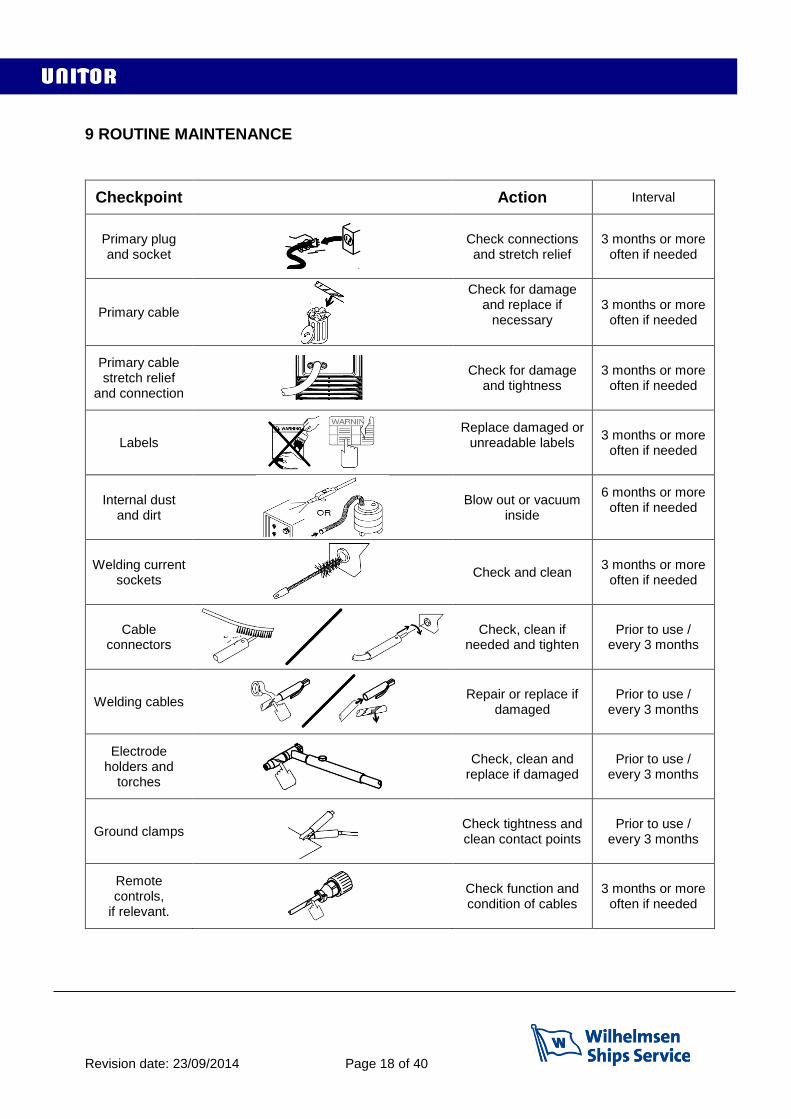
9 ROUTINE MAINTENANCE
Checkpoint Action Interval
Primary plug and socket
Check connections and stretch relief
3 months or more often if needed
Primary cable
Check for damage and replace if
necessary
3 months or more often if needed
Primary cable stretch relief
and connection
Check for damage and tightness
3 months or more often if needed
Labels
Replace damaged or unreadable labels
3 months or more often if needed
Internal dust and dirt
Blow out or vacuum inside
6 months or more often if needed
Welding current sockets
Check and clean 3 months or more
often if needed
Cable connectors
Check, clean if needed and tighten
Prior to use / every 3 months
Welding cables
Repair or replace if damaged
Prior to use / every 3 months
Electrode holders and
torches
Check, clean and replace if damaged
Prior to use / every 3 months
Ground clamps
Check tightness and clean contact points
Prior to use / every 3 months
Remote controls,
if relevant.
Check function and condition of cables
3 months or more often if needed
Revision date: 23/09/2014 Page 19 of 40
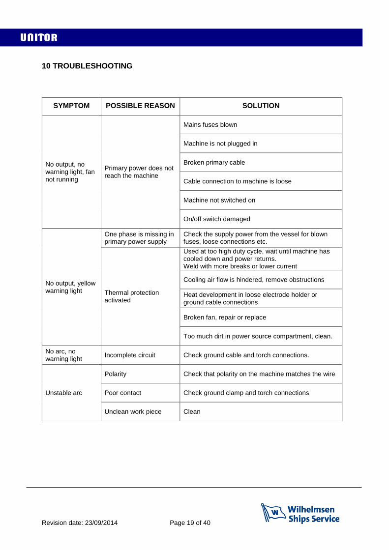
10 TROUBLESHOOTING
SYMPTOM
POSSIBLE REASON
SOLUTION
No output, no warning light, fan not running
Primary power does not reach the machine
Mains fuses blown
Machine is not plugged in
Broken primary cable
Cable connection to machine is loose
Machine not switched on
On/off switch damaged
No output, yellow warning light
One phase is missing in primary power supply
Check the supply power from the vessel for blown fuses, loose connections etc.
Thermal protection activated
Used at too high duty cycle, wait until machine has cooled down and power returns. Weld with more breaks or lower current
Cooling air flow is hindered, remove obstructions
Heat development in loose electrode holder or ground cable connections
Broken fan, repair or replace
Too much dirt in power source compartment, clean.
No arc, no warning light
Incomplete circuit Check ground cable and torch connections.
Unstable arc
Polarity Check that polarity on the machine matches the wire
Poor contact Check ground clamp and torch connections
Unclean work piece Clean

Revision date: 23/09/2014 Page 20 of 40
RESETTING SOFTWARE Unidentified software problems may prevent the welding power source from functioning correctly. If normal troubleshooting does not help the below software reset procedure should be used. The reset procedure involves complete restoration of the default values, parameters and memory settings to original values.
UWI-500TP -Switch the welding machine off. -While pressing buttons A and B switch the machine on. -Release buttons A and B. The message REC will appear on the display. When the message disappears the machine is ready
UWF-102 -Switch the welding machine off and connect the wire feeder. -While pressing buttons C and D switch the machine on. -Release buttons C and D. The message rEC FAC will appear on the displays of the wire feeder. When the message disappears the machine is ready
A B
D C
Revision date: 23/09/2014 Page 21 of 40
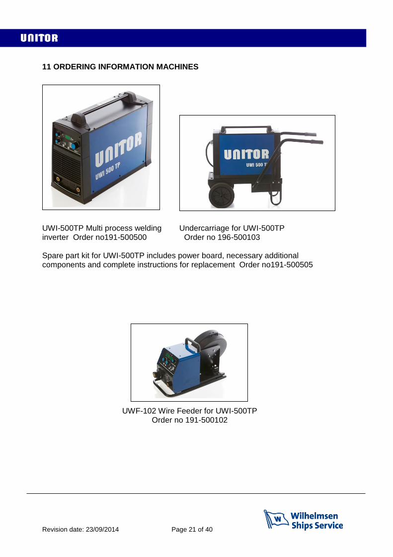
11 ORDERING INFORMATION MACHINES
UWI-500TP Multi process welding Undercarriage for UWI-500TP inverter Order no191-500500 Order no 196-500103 Spare part kit for UWI-500TP includes power board, necessary additional components and complete instructions for replacement Order no191-500505
UWF-102 Wire Feeder for UWI-500TP Order no 191-500102

Revision date: 23/09/2014 Page 22 of 40
12 ORDERING INFORMATION BASIC ACCESSORIES
Basic accessories
Basic accessories kit for UWI-500TP 196 670406
Consisting of: (Order numbers to be used when re-ordering)
Flip-Vision shield with flip-up frame, head band and filter shade 11 glass 196 709485
Long lined welding gloves, 1pair (re-ordering number is for 6 pairs) 196 632786
Electrode holder with 3m cable and connector 196 594325
Ground clamp with 3m cable and connector 196 594317
Wire brush, steel, 2 rows, 1 pcs (re-ordering number is for 6 pcs) 196 632 976
Chipping hammer steel, 1 pcs (re-ordering number is for 2pcs) 196 633008
Remote control with 8m cable 191 670414
Air Carbon Arc gouging accessories
ACA-torch 600A with cable & safety connector, air hose & quick connector
196 528703
Cable connector conversion, safety connector to DIX for UWI connection 195 634121
Shielding gas supply
Argon regulator with flow adjustment 0-32 l/min 197 510010
Flow control meter for use at torch nozzle 197 597328
Flow control needle valve for gas flow adjustment 197 597310
TIG welding Accessories
Specially thin and soft TIG gloves, 6 pairs 197 632794
TIG-torch T-200 with gas valve and DIX 70 connector 197 200000
Accessories kit for TIG-torch 197 607810
Wire welding Accessories
Torch for gas shielded wire welding 193 607451
Torch for gasless wire welding 193 750179
Special pliers for wire welding 193 591990
Anti-spatter spray for nozzle protection 193 633149
Flow-control meter for use at torch nozzle 197 597328
Shielding gasses
Argon and Argon/CO2 80/20 is available in 10 l cylinders and 50 l cylinders. Pure CO2 is available on request
Revision date: 23/09/2014 Page 23 of 40
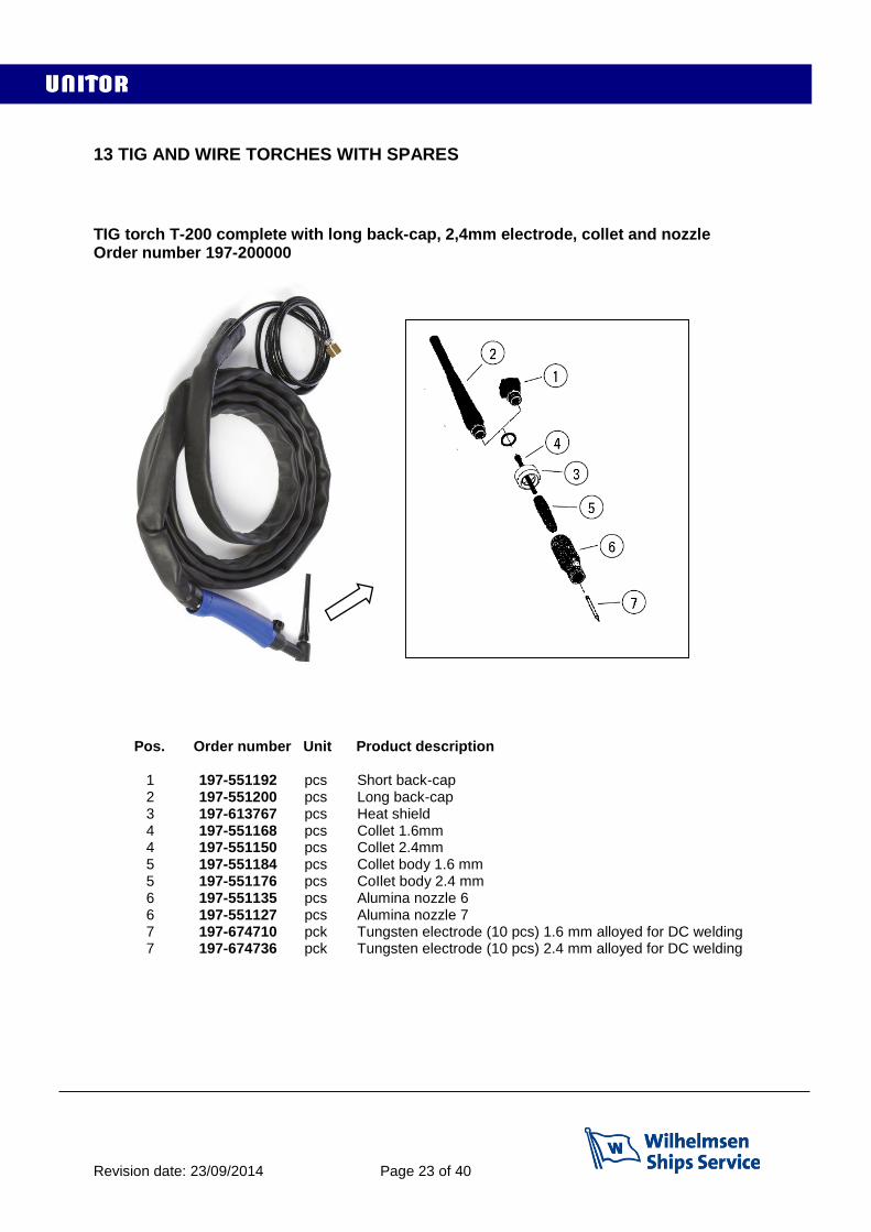
13 TIG AND WIRE TORCHES WITH SPARES TIG torch T-200 complete with long back-cap, 2,4mm electrode, collet and nozzle Order number 197-200000
Pos. Order number Unit Product description
1 197-551192 pcs Short back-cap 2 197-551200 pcs Long back-cap 3 197-613767 pcs Heat shield 4 197-551168 pcs Collet 1.6mm 4 197-551150 pcs Collet 2.4mm 5 197-551184 pcs Collet body 1.6 mm 5 197-551176 pcs CoIlet body 2.4 mm 6 197-551135 pcs Alumina nozzle 6 6 197-551127 pcs Alumina nozzle 7
7 197-674710 pck Tungsten electrode (10 pcs) 1.6 mm alloyed for DC welding 7 197-674736 pck Tungsten electrode (10 pcs) 2.4 mm alloyed for DC welding

Revision date: 23/09/2014 Page 24 of 40
T-400 torch for gas shielded wire welding, complete with contact tip 1,0-1,2mm and Teflon liner. Order number 193-607451
Pos. Order number Unit Product description
1 193-551192 pcs Gas nozzle for torch 2 193-613766 set Nozzle insulator 5 pcs 3 193-594622 set Contact tips 0,6-0.8 mm 10 pcs 3 193-594630 set Contact tips 1,0-1,2 mm 10 pcs 3 193-607455 set Contact tips 1,2-1,4 mm 10 pcs 3 193-607456 set Contact tips 1,6-2,0 mm 10 pcs 4 193-613763 set Gas diffusor 5 pcs 5 193-613764 set Neck insulation 5 pcs 6 193-594606 pcs Torch liner, Teflon for 0.6-1.2 mm wire 4.5 m long 6 193-594614 pcs Torch liner, Steel for 0.6-1.0 mm wire (blue) 3.0 m long 6 193-607457 pcs Torch liner, Steel for 1.0-1,4 mm wire (red) 3.0 m long 6 193-777846 pcs Torch liner, Steel for 1,4-1,6 mm wire (yellow) 3.0 m long
1
2
3
4
5
6 inside
Revision date: 23/09/2014 Page 25 of 40
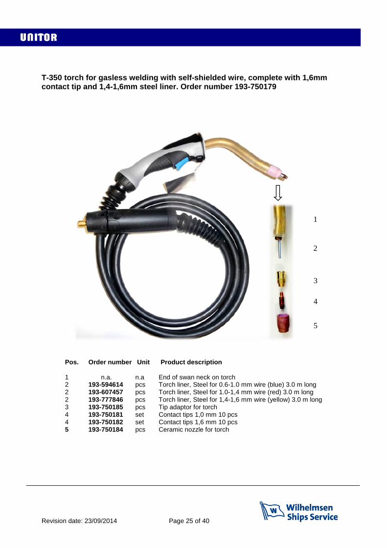
T-350 torch for gasless welding with self-shielded wire, complete with 1,6mm contact tip and 1,4-1,6mm steel liner. Order number 193-750179
Pos. Order number Unit Product description 1 n.a. n.a End of swan neck on torch 2 193-594614 pcs Torch liner, Steel for 0.6-1.0 mm wire (blue) 3.0 m long 2 193-607457 pcs Torch liner, Steel for 1.0-1,4 mm wire (red) 3.0 m long 2 193-777846 pcs Torch liner, Steel for 1,4-1,6 mm wire (yellow) 3.0 m long 3 193-750185 pcs Tip adaptor for torch 4 193-750181 set Contact tips 1,0 mm 10 pcs 4 193-750182 set Contact tips 1,6 mm 10 pcs 5 193-750184 pcs Ceramic nozzle for torch
1 1
2
3
4
5
Revision date: 23/09/2014 Page 26 of 40
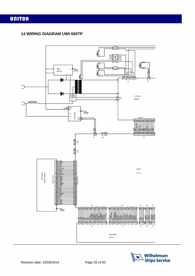
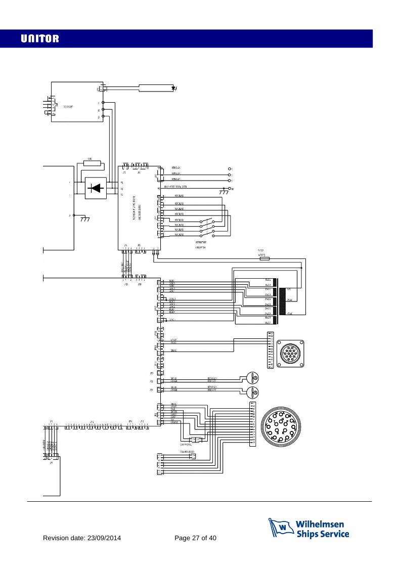
14 WIRING DIAGRAM UWI-500TP
Revision date: 23/09/2014 Page 27 of 40
Revision date: 23/09/2014 Page 28 of 40
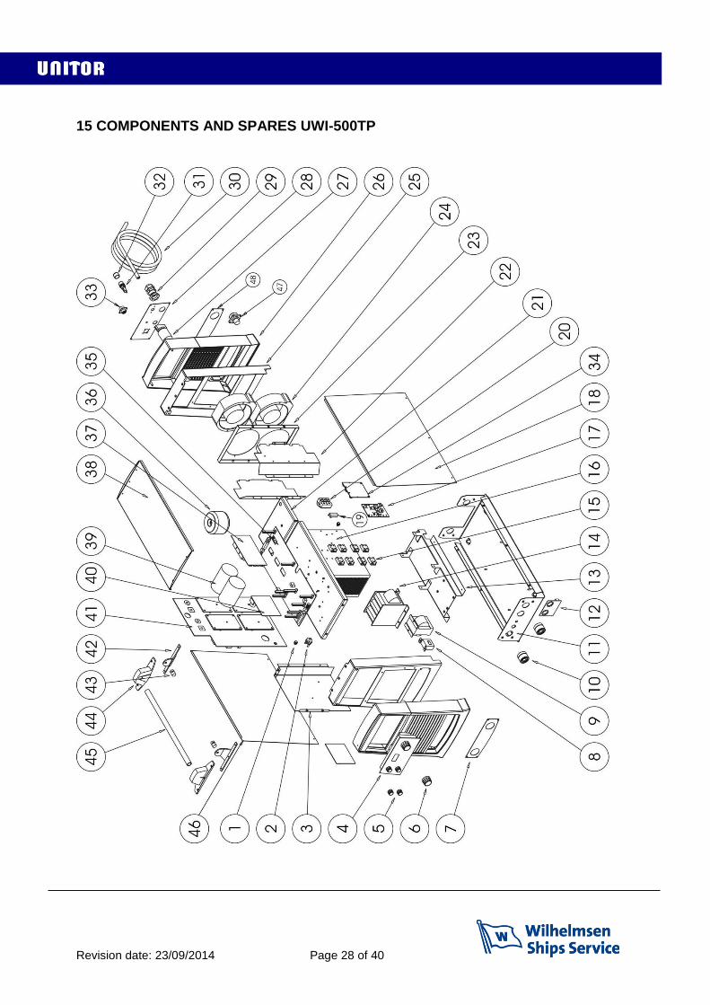
15 COMPONENTS AND SPARES UWI-500TP
Revision date: 23/09/2014 Page 29 of 40
N° CODE DESCRIPTION
1 040.0003.1002 TERMAL SWITCH L=200mm
2 040.0003.0060 TERMAL SWITCH
3 011.0013.0009 LATERAL PLATE
4 050.5308.2400 LOGIC FRONT PANEL 500
5 014.0002.0009 KNOB
6 014.0002.0017 KNOB
7 011.0013.0010 FRONT SOCKET PLATE
8 041.0004.0500 HALL SENSOR
9 044.0004.0012 OUTPUT INDUCTANCE
10 021.0001.0279 SOCKET 500A
11 011.0013.0001 LOWER COVER
12 050.0002.0056 OUTPUT FILTER BOARD
13 011.0013.0002 INTERNAL PLATE
14 042.0003.0047 POWER TRANSFORMER
15 032.0002.2003 ISOTOP DIODE
16 015.0001.0012 HEAT SINK
17 050.0001.0081 SNUBBER BOARD
18 011.0001.0512 LATERAL RIGHT COVER
19 030.0017.2202 RESISTOR
20 032.0001.8216 THREE PHASE RECTIFIER
21 011.0013.0006 UPPER PLATE
22 011.0013.0005 CONVEYOR PLATE
23 011.0013.0007 INTERNAL FAN SUPPORT
24 003.0002.0010 FAN
25 011.0013.0004 FRONT/REAR PLATE
26 010.0006.0035 FRONT/REAR PLASTIC PANEL
27 040.0001.0016 THREE-POLE SWITCH
28 013.0000.7006 REAR PANEL
29 045.0000.0017 CABLE CLAMP
30 045.0002.0009 SUPPLY CABLE
31 040.0006.1880 FUSE HOLDER
32 016.0011.0004 FUSE HOLDER CAP
33 022.0002.0268 REMOTE CONTROL WIRING
34 050.0001.0057 POWER SUPPLY CONTROL BOARD
35 050.0001.0055 BUS BOARD
36 041.0006.0006 TOROIDAL TRANSFORMER
37 050.0002.0053 LINE FILTER BOARD
38 011.0000.0500 UPPER COVER
39 031.1005.0228 CAPACITOR
40 050.0001.0052 SUPPLIES BOARD
41 050.0001.0054 POWER BOARD
42 011.0009.0047 HANDLE SUPPORT PLATE
43 016.0002.0001 PIN
44 012.0000.0005 COVER FOR HANDLE SUPPORT PLATE
45 011.0013.0013 HANDLE
46 011.0001.0513 LATERAL LEFT COVER
47 022.0002.0156 REMOTE DEVICE CONNECTION WIRING
48 011.0013.0018 REAR SOCKET PLATE
For ordering spares please state: Model: UWI 500 TP Serial no: ..………..….….
Pos no: …………………. Code: ………………….
Revision date: 23/09/2014 Page 30 of 40
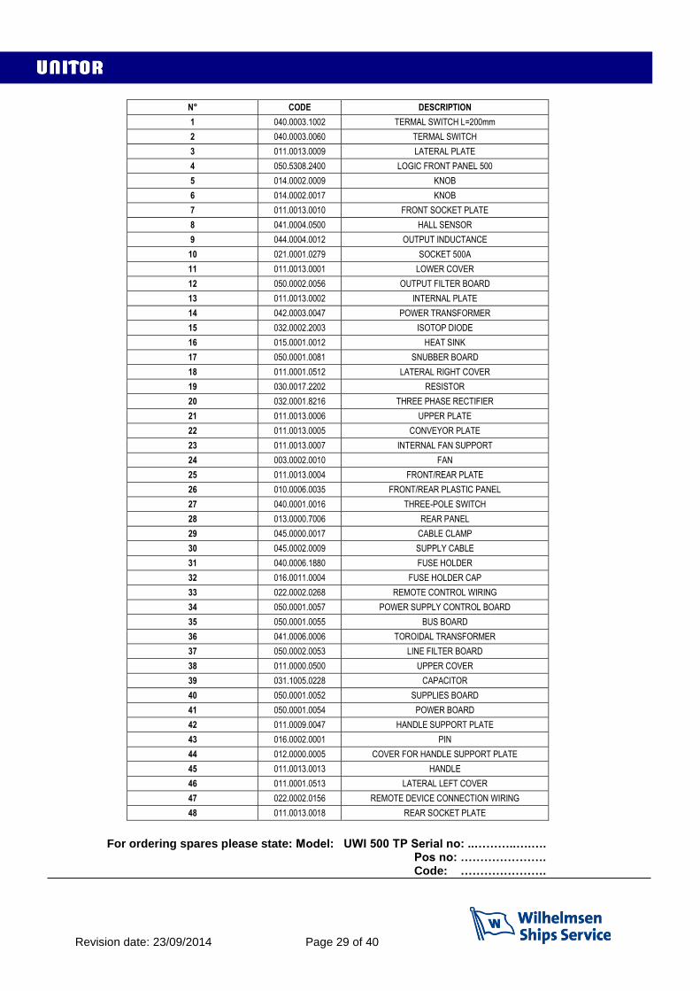
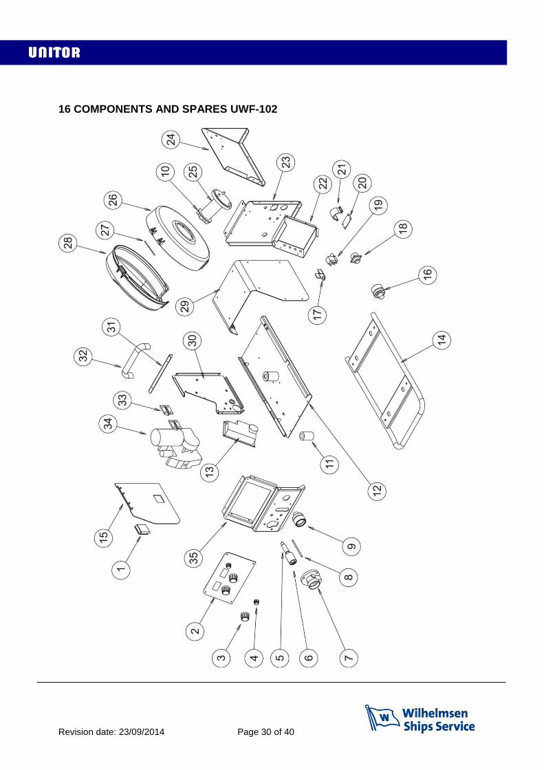
16 COMPONENTS AND SPARES UWF-102

Revision date: 23/09/2014 Page 31 of 40
N° CODE DESCRIPTION
1 011.0006.0003 SLIDE CLOSURE
2 050.5324.2400 LOGIC FRONT PANEL WF102 AIR
3 014.0002.0005 KNOB WITH POINTER
4 014.0002.0009 KNOB WITH POINTER
5 021.0001.2014 STING
6 021.0001.2000 COUPLING EURO
7 021.0001.2004 PLASTIC HOUSING
8 021.0001.2027 CAPILLARY TUBE
9 021.0001.0279 FIXED SOCKET 500A 95mmq
10 002.0000.0268 SPOOL HOLDER CAP
11 046.0004.0013 PLASTIC SUPPORT
12 011.0014.0005 LOWER COVER
13 050.0001.0041 MOTOR BOARD
14 011.0014.0012 SLIDING KIT
15 011.0001.0632 DOOR
16 021.0001.0379 FIX PLUG 500A 95mmq
17 011.0002.0018 SOLENOID VALVE PLATE
18 022.0002.0155 REMOTE LOGIC CABLE
19 017.0001.5542 SOLENOID VALVE
20 011.0014.0016 FIXING CABLE BUNDLE PLATE
21 011.0014.0018 SUPPORT CABLE BUNDLE PLATE
22 011.0014.0007 LOGIC PROTECTION PLATE
23 011.0014.0002 POSTERIOR PLATE
24 011.0014.0006 SPOOL SUPPORT PLATE
25 011.0006.0054 SPOOL SUPPORT
26 012.0000.0003 LOWER SPOOL COVER
27 016.0008.0003 CYLINDRICAL PLUG
28 012.0000.0004 UPPER SPOOL COVER
29 011.0001.0652 UPPER COVER
30 011.0014.0013 INTERNAL PLATE
31 011.0014.0008 UPPER COVER SUPPORT PLATE
32 011.0006.0021 HANDLE
33 011.0006.0007 PLASTIC HINGE
34 002.0000.0012 WIRE FEED MOTOR
35 011.0014.0001 FRONT PLATE
For ordering spares please state:
Model: UWF 102 Serial no: …………. Pos no: ………….
Code: .………….
Revision date: 23/09/2014 Page 32 of 40
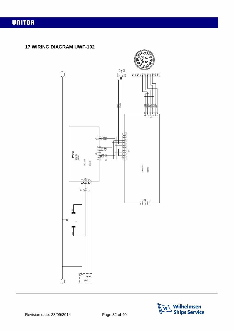
17 WIRING DIAGRAM UWF-102
Revision date: 23/09/2014 Page 33 of 40
15 SAFETY INSTRUCTIONS Arc Welding Hazards The safety information given below is only a summary of the more complete safety information found in the Safety Standards listed in Section 1-5. Read and follow all Safety Standards. Only qualified persons should install, operate, maintain, and repair this unit. During operation, keep everybody, especially children, away. ELECTRIC SHOCK can kill. Touching live electrical parts can cause fatal shocks or severe burns. The electrode and work circuit is electrically live whenever the output is on. The input power circuit and machine internal circuits are also live when power is on. In semiautomatic or automatic wire welding, the wire, wire reel, drive roll housing, and all metal parts touching the welding wire are electrically live. Incorrectly installed or improperly grounded equipment is a hazard. Do not touch live electrical parts. Wear dry, hole-free insulating gloves and body protection. Insulate yourself from work and ground using dry insulating mats or covers big enough to prevent any physical contact with the work or ground. Do not use AC output in damp areas, if movement is confined, or if there is a danger of falling. Use AC output ONLY if required for the welding process. If AC output is required, use remote output control if present on unit. Disconnect input power before installing or servicing this equipment. Always verify the supply ground − check and be sure that input power cord ground wire is properly connected to ground terminal in the cord plug and that the plug is connected to a properly grounded receptacle outlet. When making input connections, attach proper grounding conductor first − double-check connections. Frequently inspect input power cord for damage or bare wiring −replace cord immediately if damaged − bare wiring can kill. Turn off all equipment when not in use. Do not use worn, damaged, undersized, or poorly spliced cables. Do not drape cables over your body. If earth grounding of the work-piece is required, ground it directly with a separate cable. Do not touch electrode if you are in contact with the work, ground, or another electrode from a different machine. Use only well-maintained equipment. Repair or replace damaged parts at once. Maintain unit according to manual. Wear a safety harness if working above floor level. Keep all panels and covers securely in place. Clamp work cable with good metal-to-metal contact to work-piece or worktable as near the weld as practical. Insulate work clamp when not connected to work-piece to prevent contact with any metal object. Do not connect more than one electrode or work cable to any single weld output terminal. SIGNIFICANT DC VOLTAGE exists after removal of input power on inverters. Turn off inverter, disconnect input power, and discharge input capacitors before touching any parts. ARC RAYS can burn eyes and skin. Arc rays from the welding process produce intense visible and invisible (ultraviolet and infrared) rays that can burn eyes and skin. Sparks fly off from the weld. Wear a welding helmet fitted with a proper shade of filter to protect your face and eyes when welding or watching. Wear approved safety glasses with side shields under your helmet. Use protective screens or barriers to protect others from flash and glare; warn others not to watch the arc. Wear protective clothing made from durable, flame-resistant material (leather and wool) and foot protection.

Revision date: 23/09/2014 Page 34 of 40
FUMES AND GASES can be hazardous. Welding produces fumes and gases. Breathing these fumes and gases can be hazardous to your health. Keep your head out of the fumes. Do not breathe the fumes. If inside, ventilate the area and/or use exhaust at the arc to remove welding fumes and gases. If ventilation is poor, use an approved air-supplied respirator. Read the Material Safety Data Sheets (MSDSs) and the manufacturer’s instructions for metals, consumables, coatings, cleaners, and degreasers. Work in a confined space only if it is well ventilated, or while wearing an air-supplied respirator. Always have a trained watchperson nearby. Welding fumes and gases can displace air and lower the oxygen level causing injury or death. Be sure the breathing air is safe. Do not weld in locations near degreasing, cleaning, or spraying operations.The heat and rays of the arc can react with vapors to form highly toxic and irritating gases. Do not weld on coated metals, such as galvanized, lead, or cadmium plated steel, unless the coating is removed from the weld area, the area is well ventilated, and if necessary, while wearing an air-supplied respirator. The coatings and any metals containing these elements can give off toxic fumes if welded. WELDING can cause fire or explosion. Welding on closed containers, such as tanks, drums, or pipes, can cause them to blow up. Sparks can fly off from the welding arc. The flying sparks, hot workpiece, and hot equipment can cause fires and burns. Accidental contact of electrode to metal objects can cause sparks, explosion, overheating, or fire. Check and be sure the area is safe before doing any welding. Protect yourself and others from flying sparks and hot metal. Do not weld where flying sparks can strike flammable material. Remove all flammables within 35 ft (10.7 m) of the welding arc. If this is not possible, tightly cover them with approved covers. Be alert that welding sparks and hot materials from welding can easily go through small cracks and openings to adjacent areas. Watch for fire, and keep a fire extinguisher nearby. Be aware that welding on a ceiling, floor, bulkhead, or partition can cause fire on the hidden side. Do not weld on closed containers such as tanks, drums, or pipes, unless they are properly prepared Connect work cable to the work as close to the welding area as practical to prevent welding current from travelling long, possibly unknown paths and causing electric shock and fire hazards. Do not use welder to thaw frozen pipes. Remove stick electrode from holder or cut off welding wire at contact tip when not in use. Wear oil-free protective garments such as leather gloves, heavy shirt, cuff-less trousers, high shoes, and a cap. Remove any combustibles, such as a butane lighter or matches, from your person before doing any welding. FLYING METAL can injure eyes. Welding, chipping, wire brushing, and grinding cause sparks and flying metal. As welds cool, they can throw off slag. Wear approved safety glasses with side shields even under your welding helmet. BUILDUP OF GAS can injure or kill. Shut off shielding gas supply when not in use. Always ventilate confined spaces or use approved air-supplied respirator. HOT PARTS can cause severe burns. Do not touch hot parts bare handed. Allow cooling period before working on gun or torch. MAGNETIC FIELDS can affect pacemakers. Pacemaker wearers keep away. Wearers should consult their doctor before going near arc welding, gouging, or spot welding operations. NOISE can damage hearing. Noise from some processes or equipment can damage hearing. Wear approved ear protection if noise level is high.

Revision date: 23/09/2014 Page 35 of 40
CYLINDERS can explode if damaged. Shielding gas cylinders contain gas under high pressure. If damaged, a cylinder can explode. Since gas cylinders are normally part of the welding process, be sure to treat them carefully. Protect compressed gas cylinders from excessive heat, mechanical shocks, slag, open flames, sparks, and arcs. Install cylinders in an upright position by securing to a stationary support or cylinder rack to prevent falling or tipping. Keep cylinders away from any welding or other electrical circuits. Never drape a welding torch over a gas cylinder. Never allow a welding electrode to touch any cylinder. Never weld on a pressurized cylinder − explosion will result. Use only correct shielding gas cylinders, regulators, hoses, and fittings designed for the specific application; maintain them and associated parts in good condition. Turn face away from valve outlet when opening cylinder valve. Keep protective cap in place over valve except when cylinder is in use or connected for use. Read and follow instructions on compressed gas cylinders, associated equipment, and CGA publication P-1 listed in Safety Standards. Additional precautions for installation, operation, and maintenance Do not install or place unit on, over, or near combustible surfaces. Do not install unit near flammables. Do not overload building wiring − be sure power supply system is properly sized, rated, and protected to handle this unit. FALLING UNIT can cause injury. Use lifting eye to lift unit only, NOT running gear, gas cylinders, or any other accessories. Use equipment of adequate capacity to lift and support unit. If using lift forks to move unit, be sure forks are long enough to extend beyond opposite side of unit. OVERUSE can cause OVERHEATING Allow cooling period; follow rated duty cycle. Reduce current or reduce duty cycle before starting to weld again. Do not block or filter airflow to unit. STATIC (ESD) can damage PC boards. Put on grounded wrist strap BEFORE handling boards or parts. Use proper static-proof bags and boxes to store, move, or ship PC boards. MOVING PARTS can cause injury. Keep away from moving parts. Keep away from pinch points such as drive rolls. WELDING WIRE can cause injury. Do not press gun trigger until instructed to do so. Do not point gun toward any part of the body, other people, or any metal when threading welding wire. ARC WELDING can cause interference. Electromagnetic energy can interfere with sensitive electronic equipment such as computers and computer-driven equipment such as robots. Be sure all equipment in the welding area is electromagnetically compatible. To reduce possible interference, keep weld cables as short as possible, close together, and down low, such as on the floor. Locate welding operation 100 meters from any sensitive electronic equipment. Be sure this welding machine is installed and grounded according to this manual. If interference still occurs, the user must take extra measures such as moving the welding machine, using shielded cables, using line filters, or shielding the work area.
Revision date: 23/09/2014 Page 36 of 40
EMF Information Considerations about welding and the effects of low frequency electric and magnetic fields. Welding current, as it flows through welding cables, will cause electromagnetic fields. There has been and still is some concern about such fields. However, after examining more than 500 studies spanning 17 years of research, a special blue ribbon committee of the National Research Council concluded that: “The body of evidence, in the committee’s judgment, has not demonstrated that exposure to power-frequency electric and magnetic fields is a human-health hazard.” However, studies are still going forth and evidence continues to be examined. Until the final conclusions of the research are reached, you may wish to minimize your exposure to electromagnetic fields when welding or cutting. To reduce magnetic fields in the workplace, use the following procedures: 1. Keep cables close together by twisting or taping them. 2. Arrange cables to one side and away from the operator. 3. Do not coil or drape cables around your body. 4. Keep welding power source and cables as far away from operator as practical. 5. Connect work clamp to workpiece as close to the weld as possible. About Pacemakers: Pacemaker wearers consult your doctor first. If cleared by your doctor, then following the above procedures is recommended.
Revision date: 23/09/2014 Page 37 of 40

Revision date: 23/09/2014 Page 38 of 40
19 NOTES ………………………………………………………………………………………………… ………………………………………………………………………………………………… ………………………………………………………………………………………………… ………………………………………………………………………………………………… ………………………………………………………………………………………………… ………………………………………………………………………………………………… ………………………………………………………………………………………………… ………………………………………………………………………………………………… ………………………………………………………………………………………………… ………………………………………………………………………………………………… ………………………………………………………………………………………………… ………………………………………………………………………………………………… ………………………………………………………………………………………………… ………………………………………………………………………………………………… ………………………………………………………………………………………………… ………………………………………………………………………………………………… ………………………………………………………………………………………………… ………………………………………………………………………………………………… ………………………………………………………………………………………………… FOR FULL INFORMATION ON THE UNITOR WELDING OFFER
Revision date: 23/09/2014 Page 39 of 40
USE THE UNITOR WELDING HANDBOOK FOR MARITIME WELDERS You can download it here http://www.wilhelmsen.com/services/maritime/companies/buss/DocLit/PorductLiterature/Pages/Maintenanceandrepair.aspx
…or contact Wilhelmsen Ships Service for a paper copy

Revision date: 23/09/2014 Page 40 of 40
Fraser/surrey Gaspe Gros Caouna Halifax Hamilton Harbour Grace Holyrood Kitimat Long Pond Marytown Montreal Nanaimo New Westminster Bc Pictou/halifax Pointe Aux Pic.quebec Port Alfred Port Cartier Port Colborne Port Hawkesbury Port Mellon Port Moody Port Of Quebec Port Weller Powell River Prince Rupert Roberts Bank Saint John Sarnia, Ontario Sept Iles Seven Islands Sorel Souris/ halifax Squamish St. Catherines St.john’s, Nfld St.romuald Stephensville Summerside/halifax Three Rivers Thunder Bay Toronto alleyfield Vancouver Victoria Weymouth Windsor Yarmouth Ancud / Laitec Antofagasta Arica Caldera Concepcion Bay Coquimbo Coronel Corral Huasco Las Ventanas Lirquen Lota Penco Puerto Montt Puerto Williams Punta Arenas Quintero San Antonio San Vicente Talcahuano Tocopilla Valparaiso Antilla Bahia Honda Banes Baracoa Cabanas Caibarien Cardenas Casilda Ceiba Hueca Cienfuegos Guantanamo Guayabal Havana Isabel De Sagua Manati Mariel Media Luna Moa Nicaro Niquero Nuevitas Pilon Puerto Padre Santiago
De Cuba Sigloo Genoa Finn Tanamo Tunas De Zaza Vita Balao Esmeraldas Guayaquil La Libertad Manta Puerto Bolivar
Freeport/bahamas Guam Mahdia Acapulco Campeche Ciudad Del Carmen Coatzacoaloos Cozumel Dos Bocas Ensenada Guaymas La Paz Lazaro Cardenas Mazatlan Progreso Puerto Vallarta Salina Cruz Tampico Topolobampo Tuxpan Vera Cruz Bonaire Bullen Bay Curacao Aguadulce Almirante Armuelles Bahia Las Minas Balboa Cristobal Manzanillo Int.term. Vacamonte Callao Chimbote Ilo Matarani Paita Pisco Guayama Guayanilla Mayaguez Ponce San Juan Yabucoa St. Vincent Chaguaramas La Brea Point Fortin Point Lisas Pointe-a-pierre Port Of Spain Tembladora Aberdeen,wa Alameda Albany,n.y. Alexandria, Va Algiers Point Amelia Anacortes, Wa Anchorage,ak Annapolis,md Antioch Aransas Pass Tx Astoria, Or Baltimore Baton Rouge Bayonne Baytown Beaumont Bellingham, Ma Bellingham, Wa Benicia, Ca Boston, Ma Bridgeport Bridgeport, Conn Brooklyn, Ny Brownsville Tx Brunswick Brunswick, Ga ucksport,me Buras Camden Camden, Nj Cameron La Chalmette Charleston, Sc Cheasapeake Chester Chicago Claymont Convent Coos Bay, Or Corpus Chr.tx Crockett Darrow Davant Deer Park Delaware City Destrehan Donaldsonville Dutch Harbor, Ak Eastport, Me Eureka Everett, Wa Fairless Hills Famagusta Ferndale,wa Freeport Tx Galveston Tx Garyville Geismar Georgetown, Sc Gloucester, Nj Good Hope Gramercy Grand Isle Grays Harbour Gretna Gulfport, Ms Harvey Honolulu, Hawaii Hoquiam, Wa Houma Jacksonville Kalama Kalama, Wa Kenai Key West Lake Charles La Long Beach Long Island, Ny Longview, Wa Loop Terminal Los Angeles Manchester, Wa Manhattan, Ny Marcus Hook, Pa Martinez Miami Mobile Morehead City Morehead City, Nc Morgan City Morrisville, Pa Myrtle Grove Naples Nederland Tx New Haven, Conn New Iberia New London New Orleans New York Newington, Nh Newport News,
Va Newport, Or Newport, Ri Nikiski Norco Norfolk Oakland Olympia, Wa Orange, Rotterdam Tx Palm Beach Panama City, Fl Pasadena
Pascagoula, Ms Paulsboro, Nj Pennsauken, Nj Pensacola, Fl Petaluma Philadelphia Piney Point, Md Pittsburg Plaquemine Point Comfort Tx Port Allen Port Angeles, Wa Port Arthur Tx Port Canaveral Port Everglades Port Hueneme Port Isabel Tx Port Manatee, Fl Port Neches Tx Port Royal, Sc Port St. Joe, Fl Port Townsend, Wa Portland, Me Portland, Or Portsmouth Portsmouth, Nh Providence, Ri Queens, Ny Redwood City Reserve Revere, Ma Richmond Richmond, Va Sacramento Salem Salem, Ma San Diego San Francisco Sandwich, Ma Savannah Searsport, Me Seattle Seward Sparrows Point St.petersburg, Fl St.rose Staten Island, Ny Stockton Tacoma, Wa Tampa Texas City The Bronx, Ny The Loop Valdez Vancouver, Wa Venice West Palm Beach Westville, Nj Wilmington, Ca
Wilmington, De Houston Wilmington,nc Yonkers, Ny Yorktown, Va Fray Bentos Jose Ignacio Montevideo Nueva Palmira Amuay Bay
Bajo Grande Cumarebo El Palito El Tablazo Guanta Guaranao Jose Bay La Guaira La Salina Maracaibo Pertigalete Puerto Cabello Puerto La Cruz Puerto Miranda Puerto Ordaz Punta Cardon Punta De Palmas Punto Fijo San Lorenzo, Vz St.croix Aeroskobing Assens Bagenkop Bogense Copenhagen Ebeltoft Enstedvaerket Havn Esbjerg Fakse Ladeplads Havn Fredericia Frederiksund Frederiksvaerk Fredrikshavn Faaborg Gedser Great Belt Grenaa Graasten Gulfhavn Haderslev Halsskov Hanstholm Helsingor Hirtshals Hobro Holbaek
Horsens Kalundborg Kertminde Koge Kolding Korsor Lemvig Mariager Marstal Oslo Middlefart Naestved Nakskov Nyborg Nykobing
Falster Nykobing Mors Nykobing Skjaelland Odense Orehoved Falster Randers Ronne Rudkobing Sakskobing Skaelskor Skaerbaek Skagen Skive Sonderborg Stege Stigsnaesvaerkets Havn Svendborg Studstrupvaerkets Havn Thisted Thorshavn Vejle Vordingborg Aabenraa Aalborg Aarhus Kunda Loksa Muuga Paldiski Paljassaare Parnu Tallinn Dalsbruk Hamina/fr.havn Hanko/hangoe Helsinki Ingaa/inkoo Jakobstad Kalajoki Kantvik Kaskinen/kasko Kemi Kemio Kokkola/karleby Kotka Koverhar Kristinestad Lappvik Lovisa Mariehamn Merikarvia Nystad Naantali Oulu Pargas Pori Porvoo/borgaa Rauma Raahe/brahestad Skoeldvik Tammisaari Teijo Tolkis Torneaa Turku Valkom/valko Vaasa Akureyri Isafjørdur Reykjavik Arklow Aughinish Bantry Cork Drogheda Dublin Dun Laoghaire Dundalk Foynes Galway Limerick Moneypoint Ringaskiddy Tarbert Waterford Liepaja Mersrags Riga Roja Salacgriva Skulte Ventspils
Butinge Klaipeda Agnefest Alta Piraeus Arendal Asker Askoy Aukra Aure Averoey Bergen Berlevaag Bodoe Boemlo Brattvag Breivika
Brevik Baatsfjord Dirdal Drammen Dusavik Egersund Eide Elnesvaagen Eydehavn Fagerstrand Farsund Finnsnes Flekkefjord Floroe Flaam Fosnavaag Fraena Fredrikstad Frei Gamvik Genoa Geiranger Gjemnes Glomfjord Gravdal Grimstad Gudvangen Halden Halsa
Hammerfest Harstad Haugesund Hellesylt Heroeya Hjelmeland Hoeyanger Holla Holmestrand Hommelvik Honningsvaag Horten Husnes
Jelsa Jessheim Joerpeland Joessinghamn Kambo Karmoey Kirkenes Singapore Krageroe Kristiansand Kristiansund Kvinesdal
Kyrksaeterora Kaarsto Larvik Leknes Lillesand Lyngdal Mandal Mehavn Mo I Rana Molde Mongstad Mosjoen Moss Muruvik Maaloey Namsos Narvik Nesset Odda Oelen Oersta Orkanger Porsgrunn Rafnes Randaberg Raubergvika Risoer Sandefjord Sandnes Sandnessjoen Sarpsborg Sauda Skien Skjervoey Slagen Slagentangen Smoela Soevik Sola Sorreisa Sortland Stavanger Stord Sture
Sunndalsoera Dubai Surnadal Svelgen Svolvaer Tananger Tau Thamshamn Tingvoll Tjeldbergodden Toensberg Tofte Tomrefjord
Tromsoe Trondheim Tustna Tvedestrand Tyssedal Tysvaer Ulsteinvik Vadsoe Vardoe Verdal Vik Volda Aagotnes Aaheim Aalesund Aalvik Aardal i Ryfylke Aardalstangen Gdansk Gdynia Kolobrzeg Police Swinoujscie Szczecin Arkangelsk Baltiysk De Kastri Kaliningrad Kandalaksha Kavkaz Kronshtadt Lomonosov Murmansk Nakhodka Novorossiysk Primorsk Sakhalin Sakhalin Severomorsk St. Petersburg Svetlyi Taman Temruk Temryuk Tuapse Vladivostok Vostochniy, Port Vostochnyi Vyborg Bohus Brofjorden Falkenberg Gavle Gothenburg Hallstavik Halmstad Helsingborg Hoganas Holmsund Hudiksvall Iggesund Kalmar Karlshamn Karlskrona Karlstad Koeping Landskrona Lidkoping Lilla Edet Luleaa Lysekil Malmoe Mariestad Marstrand Munkedal Norrkoeping Norrsundet Norrtalje Nynashamn
Rotterdam Ornskoldsvik Oskarshamn Oxelosund Pitea Shanghai Simrishamn Skarhamn Skelleftehamn Skutskar Slite Soderhamn
Sodertalje Solvesborg Stenungsund Stockholm Stromstad Sundsvall Surte Trelleborg Uddevalla Umeaa Varberg Vastervik Vasteraas Visby Wallhamn Ystad Aberdeen Appledore Arbroath Ardersier Ardrossan Avonmouth Ayr Ballycastle Banff Barking Barnstaple Barrow In Furness Barry Barton On Humber Belfast Berwick Upon Tweed Billingham Birkenhead Blyth Boston Bowling Braefoot Bay Bridgend Bridlington Bridport Bristol Briton Ferry Brixham Bromborough Buckie Burntisland Burton Upon Stather Caernarvon Campbeltown Canvey Island Cardiff Carrickfergus Carrington Clacton On Sea Coleraine Connah’s Quay Coryton Cowes Dagenham Dartford Dartmouth Dover Dundee Eastham Ellesmere Port Erith Falmouth Faversham Fawley Felixstowe Finnart Fishguard Fleetwood Flixborough Folkestone Fort William Forth Fowey Fraserburgh Gainsborough Garston Gateshead Gillingham Girvan Glasgow Glasson Dock Glenrothes Gloucester Goole Gourock Grangemouth Granton Gravesend Great Yarmouth Greenhithe Greenock Grimsby Guernsey Gunness Hamble Hartlepool Harwich Hebburn Heysham Holyhead Hull Humber Hunterstone Immingham Invergordon Inverkeithing Inverness Ipswich Irvine Isle Of Grain Jarrow Jersey Kilkeel Killingholme
Instruction manual & spare part list
We service your needs in 2 200 ports…