instruction manual model 250 multi-function display ... · model 251 multi-function display (pulse...
TRANSCRIPT

Instruction Manual
Model 250 Multi-Function Display (analog input)Model 251 Multi-Function Display (pulse input)Also, Model 250E & 251E for European applications
Revision A, September 2000
Please read instruction manual completely beforeattempting to operate display unit!
SEE QUICK TIPS ON PAGE 2 TO GET GOINGIN JUST MINUTES!
The Model 250 & 251 Digital Displays from McMillan Company allow you to use your flowsensor to its fullest potential. Imagine being able to program a 16-point calibration curveinto a unit (9 points on the 251), and have it display the corrected values, evenretransmitting the linearized signal with the optional analog output card! Imagineprogramming in alarm setpoints, with actual relay contacts, with hysteresis and startupoptions. The easy-to-use, menu driven interface makes programming a snap, and thebright LED display ensures clarity even under bright light conditions. The units even providea 12VDC power source for connecting most McMillan Company flow sensors, saving youmoney on additional power supplies.

2
TABLE OF CONTENTS
A. INSTALLATION1. Removing the unit from its packaging .......................................................................32. Installing any option cards (250-10 or 250-11) ........................................................33. Setting the internal jumpers and switches ................................................................44. Installing the meter in a panel.....................................................................................45. Making the electrical connections..............................................................................5
B. PROGRAMMING THE DISPLAY1. Navigating the menus ..................................................................................................82. Programming the input parameters for the Model 250...........................................9
Programming input values.........................................................................................9Programming front-panel function keys................................................................ 10Display and Program Lockout Configuration....................................................... 11Programming Totalizer Display ............................................................................. 12
3. Programming the input parameters for the Model 251........................................ 13Programming Totalizer Values .............................................................................. 13Programming front-panel function keys................................................................ 15Display and program lockout configuration.......................................................... 15Programming the Flow Rate Display .................................................................... 16
4. Programming your 250-10 Analog Output Card (optional)................................. 175. Programming your 250-11 Alarm Output Card (optional)................................... 18
Model 250 ................................................................................................................. 18Model 251 ................................................................................................................. 20
C. OPERATING THE DISPLAY1. Monitoring the Totalizer (if enabled) ....................................................................... 222. Monitoring the Flow Rate Display (if enabled) ...................................................... 223. Monitoring and Changing the Setpoints (if installed and enabled).................... 23
D. DIMENSIONS........................................................................................................................ 23
E. SPECIFICATIONSModel 250 ....................................................................................................................... 23Model 251 ....................................................................................................................... 24Optional Output Cards................................................................................................... 25
F. LIMITED WARRANTY ........................................................................................................ 26
QUICK TIPS1. Do not skip sections! It is very important to follow the manual step-by-step to keep from getting lost.2. Write down all your values as you program them in – this will make slight adjustments later a snap!3. If you get lost during Programming, just press DSP – it will return you to Ready Mode.4. Send your unit into the factory for custom programming of setpoints, calibration curves, etc.

3
Figure A.1. Diagram of option card locations.
A. Installation
1. Removing the unit from its packagingIt is very important to carefully remove all items from the packaging. Your Model 250/251 packagingshould include the following:
a. Digital display unitb. Power cord (USA for Model 250/251, European for Model 250E/251E)c. Panel gasket (for sealing unit)d. Panel latch to mount unit (usually already installed on display unit)e. Instruction manualf. Any option cards you may have ordered
2. Installing any option cards (250-10 or 250-11)If you ordered the 250-10 Analog Output card or the 250-11 Alarm Output card, you must install thesecards before proceeding with the installation of the meter. If not, skip to section 3.
To access the card slots on the Model 250/251, remove the main assembly from the rear of the case.Squeeze the finger holds on the rear cover, or use a small screwdriver to depress the side latches to
release it from the case. It is notnecessary to separate the rear cover fromthe main circuit card.
Inside, there are three card slots.Remove your option card from thepackaging, taking care to protect the cardagainst electrostatic damage. Install thecard in the appropriate slot as shown inFigure A.1, with the terminal strip towardsthe rear of the display unit.
Once the card has been installed,reassemble the case by sliding the meterbase back into the meter case. The caseis locked when the latch locks into thecase slot.
Apply the option card label (included with option card) to the bottom side of the meter. Do not coverthe vents on the top surface of the meter. The surface of the case must be clean for the label toadhere properly. Apply the label to the area designated by the large case label.
NOTE: Do not adjust or change any jumper or DIP switch settings inside the display unit unlessindicated in section 3 below. Doing so may alter the function of the unit.

4
Figure A.2. Installation of the display in a panel.
3. Setting the internal jumpers and switchesIf you are using the Model 106 Flo-Sensor with the Model 251 Display, you must first set the DIP switchinside of the unit. NOTE: Unless you are using the Model 106 with the Model 251, do not change anyjumper or switch settings inside the unit. Doing so may alter the function of the unit.
To access the DIP switch on the Model 251, remove the meter base from the meter case by firmlysqueezing and pulling back on the side rear finger tabs. This should lower the latch below the case slot(which is located just in front of the finger tabs). It is recommended to release the latch on one side,then start the other side latch.
The DIP switch is located near the center of the printed circuit board. If using the Model 106 with theModel 251, turn switch #2 OFF. All other switches should also be OFF.
Reassemble the case by sliding the meter base back into the meter case. The case is locked when thelatch locks into the case slot.
NOTE: For all McMillan products other than the 106, switch #2 should be left ON.
4. Installing the meter in a panelThe Model 250/251 meets NEMA 4X/IP65 requirements for indoor use when properly installed. Theunit is intended to be mounted in an enclosed panel. Prepare the panel cutout to the dimensionsshown in Figure A.2. Remove the panel latch from the unit. Slide the panel gasket over the rear of the
unit to the back of the bezel.The unit should be installedfully assembled. Insert theunit into the panel cutout.
While holding the unit inplace, push the panel latchover the rear of the unit sothat the tabs of the panellatch engage in the slots ofthe case. The panel latchshould be engaged in thefarthest forward slot possible.To achieve a proper seal,tighten the latch screwsevenly until the unit is snug inthe panel (torque toapproximately 7 in/lbs). Donot over-tighten the screws.
Notes about environment: The unit should be installed in a location that does not exceed maximumoperating temperature and provides good air circulation. Placing the unit near devices that generateexcessive heat should be avoided.

5
CAUTION: The bezel should be cleaned only with a soft cloth and neutral soap product. DO NOTUSE SOLVENTS! Continuous exposure to direct sunlight may accelerate the aging process of thebezel. Do not use tools of any kind (screwdrivers, pens, pencils, etc.) to operate the keypad of the unit.
5. Making the Electrical Connections
After removing the unit from the packaging, you may begin wiring the unit into your application.
Electrical connections are made via screw-clamp terminals located on the back of the meter. Allconductors should conform to the meter’s voltage and current ratings. All cabling should conform toappropriate standards of good installation, local codes, and regulations. It is recommended that thepower supplied to the meter (AC) be protected by a fuse or circuit breaker.
When wiring the meter, compare the numbers embossed on the back of the meter case against thoseshown in the tables below (step b) for proper wire position. Strip the wire, leaving approximately 0.3”(7.5 mm) bare lead exposed (stranded wires should be tinned with solder). Insert the lead under thecorrect screw-clamp terminal and tighten until wire is secure. Pull on wire to verify tightness. Eachterminal can accept up to one #14 AWG (2.55 mm) wire, two #18 AWG (1.02 mm), or four #20 AWG(0.61 mm).
a. You must first connect the power to the unit. Take the provided power cord out of the packaging.Insert the two wires in the screw-clamp terminal strip, on positions 1 & 2 labeled AC. It is notimportant which wire goes to which position, as long as b oth are securely tight and properlyinserted into positions 1 & 2.
CAUTION: When dealing with high voltage, take extra precaution. Insure that the power cordis not plugged in when connecting it to the display. Also, insure that no extra bare copper isleft after the wires are tightened down.
b. Now it is time to make the connections to the flow sensor. Select your McMillan product below andmake the connections as indicated. Connect the colored wires as indicated to the appropriatescrew-terminal:
100, 110, S-110, S-113, 101, 102, S-111, S-112, S-114, G111, G112These products require the 100-17 cable assembly to be connected to the Model250 Display. If you did not order this cable, please contact the factory to order onefor each flow sensor you purchased.These products are only compatible with the Model 250.
100-17 Cable Rear Terminal Position (Model 250/250E)RED Position 6 (+EXCITATION)
WHITE Position 3 (VOLT/OHM)BLACK Position 5 (COMM)
6
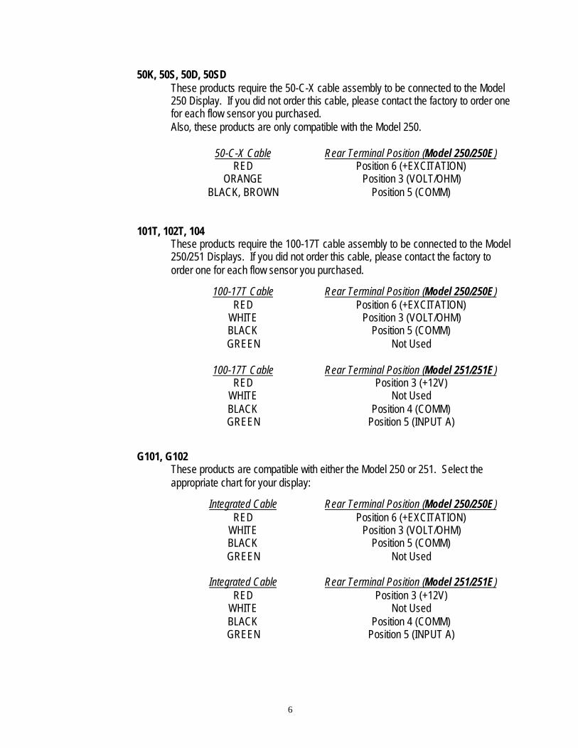
50K, 50S, 50D, 50SDThese products require the 50-C-X cable assembly to be connected to the Model250 Display. If you did not order this cable, please contact the factory to order onefor each flow sensor you purchased.Also, these products are only compatible with the Model 250.
50-C-X Cable Rear Terminal Position (Model 250/250E)RED Position 6 (+EXCITATION)
ORANGE Position 3 (VOLT/OHM)BLACK, BROWN Position 5 (COMM)
101T, 102T, 104These products require the 100-17T cable assembly to be connected to the Model250/251 Displays. If you did not order this cable, please contact the factory toorder one for each flow sensor you purchased.
100-17T Cable Rear Terminal Position (Model 250/250E)RED Position 6 (+EXCITATION)
WHITE Position 3 (VOLT/OHM)BLACK Position 5 (COMM)GREEN Not Used
100-17T Cable Rear Terminal Position (Model 251/251E)RED Position 3 (+12V)
WHITE Not UsedBLACK Position 4 (COMM)GREEN Position 5 (INPUT A)
G101, G102These products are compatible with either the Model 250 or 251. Select theappropriate chart for your display:
Integrated Cable Rear Terminal Position (Model 250/250E)RED Position 6 (+EXCITATION)
WHITE Position 3 (VOLT/OHM)BLACK Position 5 (COMM)GREEN Not Used
Integrated Cable Rear Terminal Position (Model 251/251E)RED Position 3 (+12V)
WHITE Not UsedBLACK Position 4 (COMM)GREEN Position 5 (INPUT A)
7
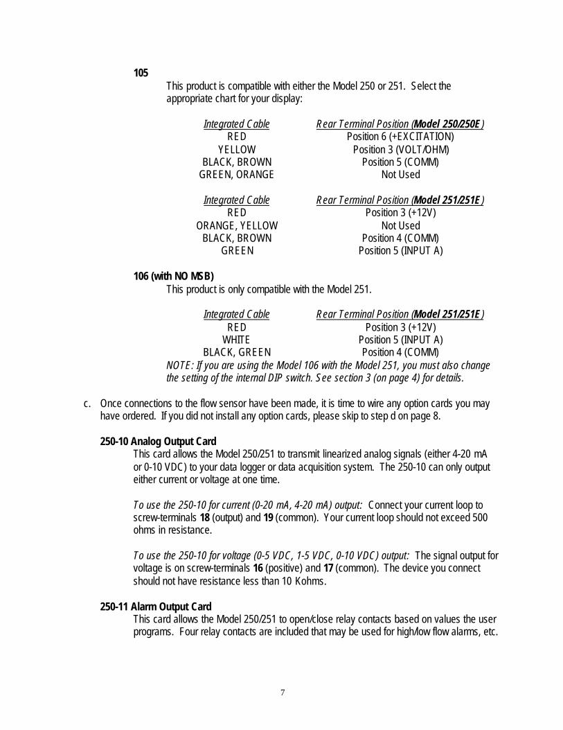
105This product is compatible with either the Model 250 or 251. Select theappropriate chart for your display:
Integrated Cable Rear Terminal Position (Model 250/250E)RED Position 6 (+EXCITATION)
YELLOW Position 3 (VOLT/OHM)BLACK, BROWN Position 5 (COMM)
GREEN, ORANGE Not Used
Integrated Cable Rear Terminal Position (Model 251/251E)RED Position 3 (+12V)
ORANGE, YELLOW Not UsedBLACK, BROWN Position 4 (COMM)
GREEN Position 5 (INPUT A)
106 (with NO MSB)This product is only compatible with the Model 251.
Integrated Cable Rear Terminal Position (Model 251/251E)RED Position 3 (+12V)
WHITE Position 5 (INPUT A)BLACK, GREEN Position 4 (COMM)
NOTE: If you are using the Model 106 with the Model 251, you must also changethe setting of the internal DIP switch. See section 3 (on page 4) for details.
c. Once connections to the flow sensor have been made, it is time to wire any option cards you mayhave ordered. If you did not install any option cards, please skip to step d on page 8.
250-10 Analog Output CardThis card allows the Model 250/251 to transmit linearized analog signals (either 4-20 mAor 0-10 VDC) to your data logger or data acquisition system. The 250-10 can only outputeither current or voltage at one time.
To use the 250-10 for current (0-20 mA, 4-20 mA) output: Connect your current loop toscrew-terminals 18 (output) and 19 (common). Your current loop should not exceed 500ohms in resistance.
To use the 250-10 for voltage (0-5 VDC, 1-5 VDC, 0-10 VDC) output: The signal output forvoltage is on screw-terminals 16 (positive) and 17 (common). The device you connectshould not have resistance less than 10 Kohms.
250-11 Alarm Output CardThis card allows the Model 250/251 to open/close relay contacts based on values the userprograms. Four relay contacts are included that may be used for high/low flow alarms, etc.

8
Two relays are utilized, each providing two outputs sharing a common ground. Relay1 hascontacts on screw-terminal 20 (output) and 21 (common). Relay2 has contacts on screw-terminal 21 (common) and 22 (output). Both share 21 as a common contact.
Relay3 has contacts on screw-terminal 23 (output) and 24 (common). Relay4 hascontacts on 24 (common) and 25 (output). Both share 24 as a common contact.
Please note that these contacts should not switch more than 250V or 3 amps each.
d. Once wiring is complete, it is time to power up the unit. Connect the power cord to AC power, andthe unit should initialize, turning each LED segment on as a self-test, then displaying informationabout software version. After a few seconds, the unit should enter Ready Mode and display zeros(assuming it has not been used before).
Now, the unit must be programmed before use.
B. Programming the Display
1. Navigating the menusIn order to program the display, you must understand how the front panel buttons are used to navigatethrough the menus.
Also, the display unit can be in two different modes: Ready and Program. In Ready mode, it ismonitoring, totalizing, and displaying current status. Program mode is used to calibrate, adjustsetpoints, and configure options. Program mode is easily identified – while in Program mode, thedisplay will alternate between the current menu selection and the value.
The buttons on the front of the unit perform the following functions:
DSP: In Ready mode, this button cycles between the various display modes: Flow Rate, Totalizer(and Max/Min for the Model 250) Displays. In Program mode, it ends Program mode and returnsyou to Ready mode.
PAR: If in Ready mode, pressing this button will enter Program mode. Once in Program mode,this button becomes a select button, entering whatever selection is currently displayed.
F1∆: (function key 1) In Ready mode, this button can be programmed to perform various functions.In Program mode, it is used to browse forward through menus.
F2∇: (function key 2) In Ready mode, this button can be programmed to perform various functions.In Program mode, it is used to browse backwards through menus.
RST: In Ready mode, this button will reset the Totalizer display. It is disabled in Program mode.

9
2. Programming the input parameters for the Model 250If you get lost when programming, simply press the DSP button to return to Ready Mode.Skip to Section 3 on page 13 to program the Model 251.
MODEL 250 ONLYPROGRAMMING INPUT VALUES (Model 250 Only)a. If in Ready mode, press PAR to enter Program mode. The screen will alternate.b. Press the F1∆ button once. The screen should now read 1-INP (alternating).c. Press PAR to select “rANGE” (input range selection).d. Use the arrow keys (F1∆ and F2∇) to browse until you find “20v” (the v looks like the letter u).e. Press PAR to select “20v”.f. Now the screen should read “deCPt” (display decimal point).g. Using the arrow keys, select the number of decimals you wish to display. This setting only
affects the Flow Rate, Max, and Min Displays. The Totalizer Display decimal place is set later.Keep in mind that the unit can only display 5 total digits, so if you have too many decimalplaces, your flow rate may not fully display. For example, if your maximum flow rate is 1000(i.e., mL/minute), you can only display one decimal (“1000.0”). However, if your maximumflow rate is 2 (i.e., 2 GPM), then you could display up to 4 decimal places (“2.0000”).
h. Once you have selected the number for decimals, press PAR. The screen should now read“round” (display rounding).
i. This function should always be set to “1”. Use the arrow keys to select “1” and press PAR.j. The screen should now read “FILtr” (filter setting). This value (in seconds) can be used to filter
the Flow Rate Display readout, making the readout appear smoother. Use higher numbers formore filtering, “0” for no filtering. For most applications, “1.0” provides a good balance forfiltering and response time.
k. Once you have selected your filter time, press PAR again. The screen should now read“bANd” (filter band). This value should be “10”. Once “10” is selected, press PAR.
l. The screen will now read “PtS” (scaling points). On this screen, you select how many scalingpoints you would like to program into the unit for linearization purposes. For instance, toprogram a linear display, select “2” – one point for zero and one other point.However, most McMillan flow sensors are slightly non-linear, and the Model 250 accepts up to16 linearization points for correcting that linearity. All McMillan flow sensors come with acalibration certificate that can be used for programming. If the certificate has 4 points, select“5” on the PtS screen (4 points plus zero). If the certificate has 3 points, select “4” on the PtSscreen (3 points plus zero). If you perform your own calibrations, specify the number ofcalibration points you would like to program, always adding one for zero. The calibration pointsshould be programmed in order from lowest to highest. Press PAR once your desired numberof calibration points is selected.
m. The screen will now read “StYLE” (scaling style). The Model 250 provides two options forprogramming values: Apply and Key-In. Apply mode allows you to connect the flow sensor,adjust it to a known constant flow rate, and program the display value without having to enterthe input value. In Key-In mode, you must already know the output of the flow sensor atvarious flow rates (for example, have a factory-issued calibration certificate). Select “APLY” forApply mode or “KEY” for Key-in mode. Press PAR when you have made your selection.

10
n. The screen will now show “INP 1” (input value for scaling point 1). If you are using Key-Inmode, use the arrow keys to select your first input point in volts DC (usually zero). If you areusing Apply mode, adjust flow to your first desired scaling point (usually zero). Once selected,press PAR.
o. The screen will now show “dSP 1” (display value for scaling point 1). Using the arrow keys,enter your first coordinating display value in your engineering units (i.e., mL/min, GPM, etc.).This is the number you want the Flow Rate Display to show when it receives the signal you setin step n. Press PAR when complete.
p. The screen will now show “INP 2” (input value for scaling point 2). If you are using Key-Inmode, use the arrow keys to select your second input point in volts DC (i.e., 1.25 VDC). If youselected Apply mode, adjust the flow rate of your flow sensor to your second desired scalingpoint (i.e., 125 mL/min). Once selected, press PAR.
q. The screen will now show “dSP 2” (display value for scaling point 2). Using the arrow keys,enter your second coordinating display value in your engineering units (i.e., mL/min, GPM,etc.)This is the value you want to display with the signal you set in step p. Press PAR whencomplete.
r. Continue as above through all of your scaling points. When complete, the unit will alternatebetween “Pro” and “No”. Press DSP to exit Program mode.
PROGRAMMING FRONT-PANEL FUNCTION KEYS (Model 250 only)a. If not already in Program mode, press PAR to enter it.b. Press the up arrow (F1) twice so that the screen reads “2-FNC”. Press PAR to select.c. Press PAR three times again. The screen should now read “F1” (function key 1).d. Using the arrow keys, select the function you wish the F1∆ button to perform when
momentarily pressed in Ready mode. Select from the following options:“No” – None: No function is performed if activated. This is the factory setting for
all function buttons.“rEL” - Zero (Tare) Display: Do not use.“d-rEL” - Relative/Absolute Display: Do not use. “bAt” - Store Batch Reading in Totalizer: Do not use. “r-tot” - Reset Totalizer: When activated (momentary action), rESET flashes and
the Totalizer Display resets to zero (same as pressing RST button). TheTotalizer Display then continues to operate as it is configured. Thisfunction operates independent of the selected display (i.e., Flow Rate,Max, or Min).
“r-HI” - Reset Max: When activated (momentary action), rESET flashes and theMax resets to the present Ready display value. The Max function thencontinues from that value. This selection functions independent of thecurrent selected display.
“r-Lo” - Reset Min: When activated (momentary action), rESET flashes and theMin resets to the present Ready display value. The Min function thencontinues from that value. This selection functions independent of thecurrent selected display.
“r-HL” - Reset Max an d Min: When activated (momentary action), rESET flashesand the Max and Min reset to the present Ready display value. The Max

11
and Min functions then continue from that value. This selection functionsindependent of the current selected display.
“Print” - Print Request: Do not use.“LISt”- * Select Main or Alternate Setpoints: Do not use.“r-1” - * Reset Setpoint 1 (Alarm 1): When activated (momentary action), rESET
flashes and setpoint 1 resets to normal condition. This selection functionsindependent of the current selected display.
“r-2” - * Reset Setpoint 2 (Alarm 2): Same as “r-1” for setpoint 2.“r-3” - * Reset Setpoint 3 (Alarm 3): Same as “r-1” for setpoint 3.“r-4” - * Reset Setpoint 4 (Alarm 4): Same as “r-1” for setpoint 4.“r-34” - * Reset Setpoint 3 & 4 (Alarm 3 & 4): Same as “r-1” but for both setpoints 3
& 4.“r-234” - * Reset Setpoints 2, 3, & 4 (Alarm 2, 3, & 4): Same as “r-1” but for three
setpoints 2, 3 & 4.“r-ALL” - * Reset All Setpoints (All alarms): When activated (momentary action),
rESET flashes and all setpoints are reset to normal condition. Thisselection functions independent of the current selected display.
* only available with optional 250-11 Alarm Output Card installed.
e. Once you have selected the function you desire, press PAR to select it. The screen then reads“F2”.
f. Use the arrow keys to select one of the functions as listed in step d. Press PAR whencomplete.
g. The screen will now read “rSt”. Using the arrow keys, select “r-tot” and press PAR.h. The screen will now read “Sc-F1”. Using the arrow keys, select the function you wish the F1∆
button to perform when held down for more than three seconds in Ready mode. Refer to thelist show in step d for a description of functions. Press PAR when complete.
i. The screen will now read “Sc-F2”. Using the arrow keys, select the function you wish the F2∇button to perform when held down for more than three seconds in Ready mode. Refer to thelist show in step d for a description of functions. Press PAR when complete.
s. The unit will alternate between “Pro” and “No”. Press DSP to exit Program mode.
DISPLAY AND PROGRAM LOCKOUT CONFIGURATION (Model 250 Only)a. If not already in Program mode, press PAR to enter it.b. Press the up arrow (F1) three times so that the screen reads “3-LOC”. Press PAR to select.c. The screen will now read “HI” (Max Display). It will alternate between either “rED” or “LOC”. If
the value is “rED”, the screen will be accessible in Ready mode. By using the arrow keys, youmay select “LOC”, which will disable the screen in Ready mode. Press PAR when you havemade your selection.
d. The screen will now read “Lo” (Min Display). It will alternate between either “rED” or “LOC”. Ifthe value is “rED”, the screen will be accessible in Ready mode. By using the arrow keys, youmay select “LOC”, which will disable the screen in Ready mode. Press PAR when you havemade your selection.
e. The screen will now read “tOt” (Totalizer Display). It will alternate between either “rED” or“LOC”. If the value is “rED”, the screen will be accessible in Ready mode. By using the arrow

12
keys, you may select “LOC”, which will disable the screen in Ready mode (select this mode ifyou are not going to use the Totalizer). Press PAR when you have made your selection.
f. If you do not have the 250-11 Alarm output card installed, skip to step k.g. The screen will now read “SP-1” (setpoint/alarm 1). It will alternate between either “rED”,
“LOC”, or “Ent”. If the value is “rED”, the setpoint will be visible in Ready mode, but notchangeable. By using the arrow keys, you may select “LOC”, which will disable the screen inReady mode. If “Ent” is selected, the setpoint can easily be changed from Ready Mode (mustuse a security code, see operating instructions for Set Points). Press PAR when you havemade your selection.
h. The screen will now read “SP-2” (setpoint/alarm 2). Same as step g for setpoint 2.i. The screen will now read “SP-3” (setpoint/alarm 3). Same as step g for setpoint 3.j. The screen will now read “SP-4” (setpoint/alarm 4). Same as step g for setpoint 4.k. The screen will now read “CoDE”. Using the arrow keys, entering any non-zero value will
result in a code lockout of Program mode. Parameters, such as setpoint values above with“Ent” access, will still be accessible. Access will only be allowed after entering a matchingsecurity code or universal code of 222. Once you have selected your security code (“0” todisable), press PAR to confirm and return to “Pro”. Press DSP to exit Program mode.
PROGRAMMING TOTALIZER DISPLAY (Model 250 only)If you do not want to use the totalizer, you may skip this section.a. If not already in Program mode, press PAR to enter it.b. Press the up arrow (F1) five times so that the screen reads “5-tOt”. Press PAR to select.c. The screen now reads “deCPt”. Use the arrow keys to select the number of decimal places
you require for the Totalizer Display. For most applications, this matches the Flow RateDisplay decimal point programmed at first. If a different location is desired, make the changehere, and follow procedure below for SCFAC factor. Press PAR to select decimal place.
d. The screen now reads “tBASE”. This matches the time factor used in the flow rate display.For example, if the units that are displayed in the Flow Rate Display are mL/minute, then select“In” here. If the units display on the Flow Rate Display are GPH, then select “hour” here.Press PAR when complete.
e. The screen now reads “SCFAC”. If the Totalizer Display decimal place is the same as theFlow Rate Display decimal place (most applications), this screen should be set to “1.000”. Ifthey are different, or if you require the Totalizer Display to display flow in different engineeringunits than the Flow Rate Display, follow these instructions to calculate the SCFAC factor:
1. When changing the Totalizer Display decimal point location from the Flow RateDisplay decimal point, the required SCFAC factor is multiplied by a factor of 10.Example:
Input “dECPt” = 0.0 Input “dECPt” = 0.00Totalizer“dECPt”
SCFACFactor
TotalizerdECPt
SCFACFactor
0.00 10 0.000 100.0 1 0.00 10 .1 0.0 .1
X10 .01 0 .01X100 .001 X10 .001
(x=Totalizer display is round by tens or hundreds)

13
2. When changing the Totalizer engineering units, the SCFAC is the known conversionmultiplier from Flow Rate Display units to Totalizer Display units. Example: If FlowRate Display is Gallons and the Totalizer Display needs to be in Liters, the conversionmultiplier from Gallons to Liters is 3.785. Enter 3.785 as the SCFAC factor.
3. When changing both the Totalizer Display engineering units and Totalizer Displaydecimal place then the two calculations are multiplied together. Example: Flow RateDisplay = Gallons in tenths (0.0) with Totalizer Display = whole Liters (0), the SCFACfactor would be 0.3785.
f. Once the SCFAC factor is selected, press PAR.g. The screen now reads “Locut”. If desired, use the arrow keys to select a low cut value. A low
cut value disables the Totalizer when the Flow Rate Display value falls below the valueprogrammed. Use “0” to disable. Press PAR when complete.
h. The screen now reads “P-uP”. Use the arrow keys to toggle between “NO” and “rSt”. NO willkeep Totalizer Display values even when unit is powered off and back on. rSt will reset theTotalizer upon power down. Press PAR when you have made your selection. The screenreturns to “Pro”. Press DSP to exit Program mode.
If you are using the option cards, skip to sections 4 & 5 on pages 17-18 for instructions on how toprogram them. If not, skip to Part C on page 22, Operating Your Display.
3. Programming the input parameters for the Model 251If you get lost when programming, simply press the DSP button to return to Ready Mode.Follow these instructions only for the Model 251; use the previous section to program the Model250 (see page 9).
MODEL 251 ONLYPROGRAMMING TOTALIZER VALUES (Model 251 Only)If you do not want to use the totalizer function, skip to the next section, “Display and ProgramLockout Configuration.”a. If in Ready mode, press PAR to enter Program mode. The screen will alternate.b. Press the F1∆ button once. The screen should now read 1-INP (alternating).c. Press PAR to select “A CNt”.d. Using the arrow keys (F1∆ and F2∇), browse the selections until you find “cnt”. Press PAR to
select this option.e. The screen shoud now read “ArESET”. Use the arrow keys to select “ZErO”. Press PAR to
make the selection.f. Now, the screen should say “AdECPt”. This screen sets the Totalizer Display decimal position.
Using the arrow keys, select the number of decimal places you want displayed on theTotalizer. Remember that more decimal places allows for less total flow displayed. Once youhave made your selection, press PAR. Remember this setting – you will use it in the next step.
g. The screen should read “ASCFAC”. The ASCFAC factor is used to calculate the TotalizerDisplay value. Use the following equation to determine the value of ASCFAC:
ASCFAC = X ÷ Y

14
Where X equals:AdECPt
(set in step i) Value of X0 1
0.0 100.00 1000.000 1000
0.0000 100000.00000 100000
And Y equals:Y = frequency (pps or Hz) at known flow rate
Known flow rateExample: a flow sensor outputs 353 pps (Hz) at 500 mL/minute. Y=353/500 or 0.706.
If ASCFAC is significantly greater than one (i.e., greater than 5), you may want to reduce thenumber of decimal places – the unit will have to round the display to show that many digits.To reduce the number of decimal places, press DSP to return to Ready Mode, and start overat step b.
If ASCFAC is significantly less than one (i.e., less than 0.1), you will want to use a scaledivider. You may divide the ASCFAC by 1, 0.1, or 0.01, and enter that divided value into thisscreen. In the next step, you will tell the unit what value you divided by to gain moreresolution.
Using the arrow keys, enter your final ASCFAC into the screen, and press PAR.
h. The screen should now read “ASCALr”. Using the arrow keys, select the scale divider youused in the previous step. If you did not need to use a scale divider, select “1”. Press PARwhen complete.
i. Press PAR again to skip “ACNTLd”.j. The screen should now read “A P-UP”. This allows you to set whether or not the Totalizer
Display automatically resets at power up. Select “YES” to reset at powerup, or “NO” to keepvalues from power up to power up. Press PAR to select.
k. Press PAR again to skip “PrSEN”.l. The screen should now read “B CNt”. Using the arrow keys, select “NONE”. Press PAR when
selected. You are now back to the “Pro”/”No” screen. Press DSP to exit Program mode.
PROGRAMMING FRONT-PANEL FUNCTION KEYS (Model 251 only)a. If not already in Program mode, press PAR to enter it.b. Press the up arrow (F1) twice so that the screen reads “2-FNC”. Press PAR to select.c. Press PAR three times again. The screen should now read “F1” (function key 1).d. Using the arrow keys, select the function you wish the F1∆ button to perform when
momentarily pressed in Ready mode. Select from the following options:“No” – None: No function is performed if activated. This is the factory setting for
all function buttons.

15
“dSPSEL” - Do not use.“dSPrSt” - Do not use.“LISt” - Do not use.“PrINt” - Do not use.“PrNrSt” - Do not use.“CtrStL” - Do not use.“CtrStE” - Do not use.“INHIbt” - Do not use.“StOrE” - Do not use.“SPrStL” - Do not use.“SPrStE” - Reset setpoints. Selecting this option sends you into a submenu, where
you can select by choosing “YES” or “NO” which setpoints you would likereset.
“SPHOLd” - Do not use.
e. Once you have selected the function you desire, press PAR to select it. The screen then reads“F2”.
f. Use the arrow keys to select one of the functions as listed in step d. Press PAR whencomplete.
g. The screen will now read “rSt”. Using the arrow keys, select “dSPrSt” and press PAR.h. The screen will now read “Sc-F1”. Using the arrow keys, select the function you wish the F1∆
button to perform when held down for more than three seconds in Ready mode. Refer to thelist show in step d for a description of functions. Press PAR when complete.
i. The screen will now read “Sc-F2”. Using the arrow keys, select the function you wish the F2∇button to perform when held down for more than three seconds in Ready mode. Refer to thelist show in step d for a description of functions. Press PAR when complete.
t. The unit will alternate between “Pro” and “No”. Press DSP to exit Program mode.
DISPLAY AND PROGRAM LOCKOUT CONFIGURATION (Model 251 Only)a. If not already in Program mode, press PAR to enter it.b. Press the up arrow (F1) three times so that the screen reads “3-LOC”. Press PAR to select.c. The screen will now read “A-CNt”. If you are going to use the Totalizer, select “rED”. If you
wish to disable the Totalizer, select “LOC”. Press PAR when you have made your selection.d. The screen will now read “B-CNt”. By using the arrow keys, select “LOC”. Press PAR when
you have made your selection.e. The screen will now read “C-CNt”. By using the arrow keys, select “LOC”. Press PAR when
you have made your selection.f. The screen will now read “rATE”. If you are going to use the Flow Rate Display, select “rED”.
If you wish to disable the Flow Rate Display, select “LOC”. Press PAR when complete.g. The screen will now read “HI”. By using the arrow keys, select “LOC”. Press PAR when
complete.h. The screen will now read “LO”. By using the arrow keys, select “LOC”. Press PAR when
complete.i. If you do not have the 250-11 Alarm output card installed, skip to step n.j. The screen will now read “SP-1” (setpoint/alarm 1). It will alternate between either “rED”,
“LOC”, or “Ent”. If the value is “rED”, the setpoint will be visible in Ready mode, but not

16
changeable. By using the arrow keys, you may select “LOC”, which will disable the screen inReady mode. If “Ent” is selected, the setpoint can easily be changed from Ready Mode (mustuse a security code, see operating instructions for Set Points). Press PAR when you havemade your selection.
k. The screen will now read “SP-2” (setpoint/alarm 2). Same as step g for setpoint 2.l. The screen will now read “SP-3” (setpoint/alarm 3). Same as step g for setpoint 3.m. The screen will now read “SP-4” (setpoint/alarm 4). Same as step g for setpoint 4.n. The screen will now read “ACNtLd”. By using the arrow keys, select “LOC”. Press PAR when
complete.o. The screen will now read “bCNtLd”. By using the arrow keys, select “LOC”. Press PAR when
complete.p. The screen will now read “CCNtLd”. By using the arrow keys, select “LOC”. Press PAR when
complete.q. The screen will now read “ASCFAC”. By using the arrow keys, select “LOC”. Press PAR when
complete.r. The screen will now read “BSCFAC”. By using the arrow keys, select “LOC”. Press PAR when
complete.s. The screen will now read “CSCFAC”. By using the arrow keys, select “LOC”. Press PAR
when complete.t. The screen will now read “CoDE”. Using the arrow keys, entering any non-zero value will
result in a code lockout of Program mode. Adjustable settings, such as setpoint values, with“Ent” access, will still be accessible. Access will only be allowed after entering a matchingsecurity code or universal code of 222. Once you have selected your security code (“0” todisable), press PAR to confirm and return to “Pro”. Press DSP to exit Program mode.
PROGRAMMING THE FLOW RATE DISPLAY (Model 251 Only)If you do not wish to utilize the Flow Rate display, you may skip to the next section 4 on page 17.a. If not already in Program mode, press PAR to enter it.b. Press the up arrow (F1) four times so that the screen reads “4-rtE”. Press PAR to select.c. The screen will now show “rAtEEn”. Use the arrow keys to select “rATE-A”, and press PAR.d. The screen will now read “LO-Udt”. Use the arrow keys to select “1.0”, and press PAR.e. The screen will now read “HI-Udt”. Use the arrow keys to select “2.0”, and press PAR.f. The screen will now read “rtE dP”. This allows you to adjust the decimal position for the Flow
Rate Display. Using the arrow keys, select how many decimal places you wish to display.Remember that the more decimal places, the less digits you have for whole numbers. Forhigher flow rates, the unit may not display properly. When you have made your selection,press PAR.
g. The screen will now read “SEGS” (scaling points). On this screen, you select how manyscaling points you would like to program into the unit for linearization purposes. For instance,to program a linear display, select “1” – the display always assumes one point is zero andallows you to enter one other point.
However, most McMillan flow sensors are slightly non-linear, and the Model 251 accepts up to9 linearization points for correcting that linearity. All McMillan flow sensors come with acalibration certificate that can be used for programming. If the certificate has 4 points, select“4” on the SEGS screen. If the certificate has 3 points, select “3” on the SEGS screen. If you

17
perform your own calibrations, specify the number of calibration points you would like toprogram. The calibration points should be programmed in order from lowest to highest.
Press PAR once your desired number of calibration points is selected.
h. The screen will now show “rdSP 0”. Use the arrow keys to select zero, and press PAR.i. The screen will now show “rINP 0”. Use the arrow keys to select zero, and press PAR.j. The screen will now show “rdSP 1”. (display value for scaling point 1). Using the arrow keys,
enter your first coordinating display value in your engineering units (i.e., mL/min, GPM, etc.).This is the number you want the Flow Rate Display to show when it receives the signal you setin step k. Press PAR when complete.
k. The screen will now show “rINP 1” (input value for scaling point 1). Use the arrow keys toselect your first input point in pps (Hz) (i.e., 353 pps). Once selected, press PAR.
l. If you selected more than one scaling point, the screen will now show “rdSP 2” (display valuefor scaling point 2). Using the arrow keys, enter your second coordinating display value in yourengineering units (i.e., mL/min, GPM, etc.) This is the value you want to display with the signalyou assign for the second input value, on the next step. Press PAR when complete.
m. Continue as above through all of your scaling points. When complete, the unit will show“rOUNd”.
n. Use the arrow keys to select “1” and press PAR.o. The screen should now show “LOCUt”. Make sure the value is zero, and press PAR.p. Now, you should see “HI-t”. Make sure the value is zero, and press PAR.q. The screen should now read “LO-t”. Once again, make sure the value is zero, and press PAR.r. The screen will switch back to alternating “Pro” and “NO”. Press DSP to exit Program mode.
4. Programming your 250-10 Analog Output Card (optional)The card must already be installed as detailed in section A.2 (on page 3).a. If not already in Program mode, press PAR to enter it.b. Press the up arrow (F1) eight times so that the screen reads “8-ANA”. Press PAR to select.c. The screen will now read “tYPE”. Using the arrows, select “0-20” for 0-20 mA output, “4-20” for
4-20 mA output, or “0-10” for 0-10 VDC output (which also covers 0-5 and 1-5 VDC).d. Press PAR when you have made your selection.e. The screen will now show “ASIN”. Using the arrow keys, select from the following sources for
your analog output:MODEL 250“InP” – Flow Rate Display: The analog output is based off of the Flow Rate
Display value.“HI” - Maximum Display: The analog output is based off of the Maximum Display
value.“LO” - Maximum Display: The analog output is based off of the Maximum Display
value. “tot” - Totalizer Display: The analog output is based off of the Totalizer Display
value.MODEL 251“A CNt” – Totalizer Display: The analog output is based off of the Totalizer Display
value.

18
“B CNt” - Do not use.“C CNt” - Do not use.“rATE” - Flow Rate Display: The analog output is based off of the Flow Rate
Display value.“LO” - Do not use. “tot” - Do not use.
Press PAR when you have made your selection.
f. The screen should now read “AN-LO”. This allows you to set the value of the low end of theanalog scale (i.e., for 4-20 mA, the display value that corresponds with 4 mA). For instance, inmost cases, zero will be your low scale value. For a 1-5VDC output, you must make the lowscale value negative so that you receive a 1 VDC at zero display. A reverse acting output ispossible by reversing the scaling values. Press PAR when complete.
g. The screen should now read “AN-HI”. This allows you to set the value of the high end of theanalog scale (i.e., for 4-20 mA, the display value that corresponds with 20 mA). For instance,in most cases, your maximum flow will be your high scale value. For a 1-5VDC or 0-5VDCoutput, you must make the high scale value twice that of your maximum flow so that youreceive a 5 VDC at maximum flow display. A reverse acting output is possible by reversing thescaling values. Press PAR when complete.
h. On the Model 250, the next screen will read “udt”. Using the arrow keys, select “0.0”. PressPAR when complete.
i. You are now returned to the “Pro”/”NO” screen. Press DSP to exit Program mode.j. Check to insure the wiring is correct for your selected type of output (current or voltage) as
explained in A.5.c (on page 7).
5. Programming your 250-11 Alarm Output Card (optional)The card must already be installed as detailed in section A.2 (on page 3).
MODEL 250 ONLYa. If not already in Program mode, press PAR to enter it.b. Press the up arrow (F1) six times so that the screen reads “6-SPt”. Press PAR to select.c. The screen will show “SPSEL”. By using the arrow keys, you are able to select which setpoint
(1-4) you wish to program. The “n” in the following steps will reflect the chosen setpointnumber. After the chosen setpoint is completely programmed, the display will return to“SPSEL NO”. Repeat step for each setpoint to be programmed. Once you have selected thesetpoint you wish to program, press PAR.

19
d. The screen will now read “ACT-n”. Using the arrow keys, select the type of alarm you desire.Use figure B.1 below to determine the correct alarm for your application.
When you have made your selection, press PAR.e. The screen should now read “SP-n”. Using the arrow keys, enter your desired setpoint alarm
value. These setpoint values can also be entered in Ready Mode when the setpoint isprogrammed as “Ent” in the program/lockout configuration. Press PAR when complete.
f. The screen should now read “HYS-n”. Using the arrow keys, enter your desired hysteresisvalue. See Figure B.1 for a visual explanation of how setpoint alarm actions (balance andunbalance) are affected by the hysteresis. When the setpoint is a control output, usuallybalance hysteresis is used. For alarm applications, usually unbalanced hysteresis is used.For unbalanced hysteresis modes, the hysteresis functions on the low side for high actingsetpoints and on the high side for low acting setpoints. Press PAR when set.NOTE: Hysteresis eliminates output chatter at the switch point, while time delay can be used toprevent false triggering during process transient events.
g. The screen should now read “tON-n”. Using the arrow keys, enter the time value (in seconds)that the alarm is delayed from turning on after the trigger point is reached. A value of 0.0allows the meter to update the alarm status per the response time listed in the specifications.If the output logic is reversed (see below), this becomes off time delay. Any time accumulatedat power-off resets during power-up. Press PAR when complete.
Figure B.1. Description of setpoint alarm types for the Model 250.

20
h. The screen should now read “tOF-n”. Enter the time value in seconds that the alarm isdelayed from turning off after the trigger point is reached. A value of 0.0 allows the meter toupdate the alarm status per the response time listed in the specifications. When the outputlogic is reversed (see below), this becomes on time delay. Press PAR when complete.
i. The screen should now read “out-n”. Using the arrow keys, select “nor” for normal alarm logicor “rev” for reverse alarm logic. In “rev” mode, all diagrams shown in Figure B.1 are reversed.Press PAR when complete.
j. The screen will now read “rst-n”. Select your reset action from “Auto”, “LatC1”, or”LatC2”.“Auto” allows the alarm output to automatically reset off at the trigger points per the SetpointAction shown in Figure B.1. The alarm remains reset off until the trigger point is crossedagain.“LatC1” latches the alarm output on at the trigger point per the Setpoint Action shown in FigureB.1. Latch means that the alarm output can only be turned off by powering the unit down orusing a user-programmed function key on the front panel. When the function key is activated(momentary or maintained), the corresponding “on” alarm output is reset immediately andremains off until the trigger point is crossed again. Previously latched alarms will be off ifpower up Display is lower than setpoint value.“LatC2” latches the alarm output on at the trigger point per the Setpoint Action shown in FigureB.1. Latch means that the alarm output can only be turned off by powering the unit down orusing a user-programmed function key on the front panel. When the function key is activated(momentary or maintained), the meter delays the event until the corresponding “on” alarmoutput crosses the trigger off point. Previously latched alarms are off if power up Display valueis less than setpoint value. During a power-cycle, the meter erases a previous Latch 2 reset ifit is not activated at power up.Press PAR when you have made your reset action selection.
k. The screen should now read “Stb-n”. Select “YES” for standby operation – the alarm isdisabled until (after a power up) until the trigger point is crossed. Once the alarm is activated,the alarm operates normally per the Setpoint Action and Reset Mode. Select “NO” to disablethis feature. Press PAR when complete.
l. The screen will now read “Lit-n”. This controls the setpoint indicators on the front panel. The“OFF” mode disables the setpoint “n” indicator. The “nor” mode displays the indicator of an onalarm output. The “rEv” mode displays the setpoint indicator of off alarm outputs. The“FLASH” mode flashes the setpoint indicator of on alarm outputs. After you have made yourselection, press PAR.
m. You have now completed programming for this setpoint alarm. You may configure others (seestep c) or press DSP to exit Program Mode.
MODEL 251 ONLYa. If not already in Program mode, press PAR to enter it.b. Press the up arrow (F1) six times so that the screen reads “6-SPt”. Press PAR to select.c. The screen will show “SPSEL”. By using the arrow keys, you are able to select which setpoint
(1-4) you wish to program. The “n” in the following steps will reflect the chosen setpointnumber. After the chosen setpoint is completely programmed, the display will return to“SPSEL NO”. Repeat step for each setpoint to be programmed. Once you have selected thesetpoint you wish to program, press PAR.
d. The screen will now read “LIT-n”. This controls the setpoint indicators on the front panel. The“OFF” mode disables the setpoint “n” indicator. The “nor” mode displays the indicator of an on

21
alarm output. The “rEv” mode displays the setpoint indicator of off alarm outputs. The“FLASH” mode flashes the setpoint indicator of on alarm outputs. After you have made yourselection, press PAR.
e. The screen should now read “out-n”. Using the arrow keys, select “nor” for normal alarm logicor “rev” for reverse alarm logic. Press PAR when complete.
f. The screen should now read “SUP-n”. Select “SAVE” to restore the output to the same state itwas at before the meter powered down. Select “ON” to activate the output at startup. Select“OFF” to deactivate the output at startup. Press PAR when you have made your selection.
g. Now, the screen should read “Act-n”. This determines the setpoint action. Select “OFF” todisable the setpoint. The active settings are:
“LatCH” – With latch action the output activates when the selected display value equals thesetpoint. The output remains active until reset manually.
“bOUNd” – With boundary action, the setpoint output activates when the value is greaterthan or equal to (for hi boundaries, see below) or less than or equal to (for loboundaries, see below) the setpoint. The setpoint will automatically deactivatewhen the value falls below (or above, respectively) the setpoint.
“tOUt” – With timed out action, the action depends on the type of value the setpoint ismonitoring. For Totalizer monitoring, the setpoint activates when the Totalizervalue equals the setpoint value and deactivates after the Time Out value (setbelow). For Flow Rate monitoring, the setpoint output cycles when the rate valueis greater than or equal to (for hi boundaries, see below) or less than or equal to(for lo boundaries, see below). The Setpoint Time Out and Setpoint On Delay(both set below) determine the cycling times.
Make your selection and press PAR.h. The screen should now read “ASN-n”. Select “A-CNt” to monitor the Totalizer, or “rATE” to
monitor the Flow Rate. Do not select “B-CNt” or “C-CNt”. Press PAR when you have madeyour selection.
i. The screen will now read “SP-n”. Using the arrow keys, select your desired setpoint value.Setpoint values can also be entered when the setpoint is configured as “Ent” in theProgram/Lockout Configuration. Press PAR when complete.
j. The screen will now read “trC-n”. Select “NO” and press PAR.k. From this point on, depending on the selections you have made, different configurations will
show different options. If the option stated is not shown on your screen, move to the next step.l. Your screen may show “tYP-n”. This sets the boundary type. Select “HI” to activate the output
when the assigned value is equal or greater to the setpoint value. Select “LO” to activate theoutput when the assigned value is less than or equal to the setpoint value. Press PAR toselect.
m. Your screen may show “Stb-n”. Selecting “YES” will disable low-acting setpoints at a power upuntil the display crosses into the alarm off area. Once in the alarm off area, the setpoint willfunction according to the configured setpoint parameters. Select “NO” to disable this startupfeature. Press PAR when complete.
n. Your screen may show “HYS-n”. Using the arrow keys, set the desired hysteresis value. Thisvalue is added to (for lo boundaries) or subtracted from (for hi boundaries) the setpoint value todetermine at what value to deactivate the associated setpoint output. This function is onlyavailable for setpoints assigned to the Flow Rate Display with boundary action. Press PARwhen complete.

22
o. The screen may show “tOFF-n”. Use the arrow keys to enter a value (in seconds) for theamount of time the Flow Rate Display must meet the setpoint deactivation requirements beforethe setpoint’s output deactivates. Press PAR when complete.
p. The screen may show “tON-n”. Use the arrow keys to enter a value (in seconds) for theamount of time the Flow Rate Display must meet the setpoint activation requirements beforethe setpoint’s output activates. Press PAR when complete.
q. The screen may show “tOUT-n”. Enter a value (in seconds) that the output should be onduring a timed out cycle. For Totalizer applications, this is the amount of time the output is onafter activation. Press PAR when complete.
r. The screen may show “AUTO-n”. This controls the auto reset feature. Select “NO” to disablethis feature. Select “ZeroAS” to reset the Totalizer when the output is activated. Do notchoose any of the other selections. Press PAR when complete.
s. The screen may show “rSd-n”. Select “YES” to have the setpoint reset whenever the Totalizeris reset. Choose “NO” to disable this feature. Press PAR when complete.
t. The screen may show “rSAS-n”. Selecting “YES” will make the setpoint output deactivate(reset) when SPn+1 activates (i.e., SP1 deactivates when SP2 activates and SP4 deactivateswhen SP1 activates – the last setpoint wraps around to the first). Select “NO” to disable.Press PAR when complete.
u. If the screen shows “rSAE-n”, select “NO” and press PAR.v. When you have finished programming this setpoint, the screen will display “SPSEL”. Select
another setpoint to program (see step c) or press DSP to exit program mode.
C. Operating the Display
1. Monitoring the Totalizer (if enabled)Use the DSP button until you arrive at the Totalizer screen. The Model 250 indicates a small TOTin the left corner of the display; the Model 251 shows an A indicator in the left corner of the display.These indicate you are displaying the Totalizer.
When the Model 250 Totalizer Display exceeds 5 digits, the front panel indicator TOT flashes. Inthis case, the meter continues to totalize up to a 9 digit value. The high order 4 digits and the loworder 5 digits are displayed alternately. The letter “h” in the left of the display denotes the highorder display.
When the Model 251 Totalizer Display exceeds 5 digits, it switches to a two part display. Thisdisplay alternates between the least 6 significant digits and the remaining most significant digitsbeginning with “OF” in the display. If the display exceeds 99999999 the display will roll to zero andcontinue counting. Outputs cannot be set to counter values above 6 digits. The indicator “A” willflash when the value is above 6 digits.
To reset the Totalizer, press the RST button.
2. Monitoring the Flow Rate Display (if enabled)Use the DSP button until you arrive at the Flow Rate screen. The Model 250 turns off all indicatorsin this mode; the Model 251 shows an A indicator and displays an “r” in the left element of the LEDdisplay. These indicate you are displaying the Flow Rate Display.

23
The display shows Flow Rate in the engineering units programmed – see programming instructionsfor more details.
3. Monitoring and Changing the Setpoints (if installed and enabled)Four LED indicators are provided on the front panel: SP1, SP2, SP3, and SP4. These can beprogrammed to be on, off, or flash during alarm modes. See programming instructions for moredetails.
If you change setpoints often, it may be easiest to program all frequently used setpoints as “Ent”access (under programming, Program and Lockout Parameters). Then, by adding a security code,setpoints are quickly and easily changed by simply pressing the PAR button (in Ready Mode),selecting the appropriate setpoint and adjusting its value.
If setpoints are set to latch, the only way to reset them is to program one of the front-panel functionbuttons to reset them. Depending on your programming settings, powering off and then back onmay also reset them.
D. Dimensions
E. Specifications
MODEL 2501. DISPLAY: 5 digit, 0.56” (14.2 mm) red LED, (-19999 to 99999)2. POWER:
AC Power, 85 to 250 VAC, 50/60 Hz, 15VA.Isolation: 2300 Vrms for 1 min. to all inputs and outputs
3. KEYPAD: 2 programmable function keys, 5 keys total4. A/D CONVERTER: 16-bit resolution5. UPDATE RATES: A/D Conversion Rate: 20 readings/second6. DISPLAY MESSAGES:
“OLOL” appears when measurement exceeds + signal range“ULUL” appears when measurement exceeds – signal range“….” Appears when display values exceed + display range

24
“-…” appears when display values exceed – display range7. TOTALIZER:
Function: Time base – second, minute, hour, or dayTime accuracy: 0.01% typicalDecimal point: 0 to 0.0000Scale Factor: 0.001 to 65.000Low Signal Cutout: -19999 to 99999Total: 9 digits, display alternates between high order and low order readouts
8. CUSTOM LINEARIZATION:Data Point Pairs: selectable from 2 to 16Display Range: -19999 to 99999Decimal Point: 0.000
9. MEMORY: Nonvolatile EEPROM retains all programmable parameters and display values10. ENVIRONMENTAL CONDITIONS:
Operating temperature range: 0 to 50°C (0 to 45°C with any option cards)Storage temperature range: -40 to 60°COperating and storage humidity: 0 to 85% max non-condensingAltitude: Up to 2000 meters
11. CERTIFICATIONS AND COMPLIANCES:UL Recognized Component, File #E179259
Recognized to U.S. and Canadian requirements under the ComponentRecognition Program of Underwriters Laboratories, Inc.
Electromagnetic CompatibilityImmunity to EN 50082-2Emissions to EN 50081-2
12. CONNECTIONS:High compression cage-clamp terminal blockWire strip length: 0.3” (7.5 mm)Wire gauge capacity: (1) 14 AWG (2.55 mm) solid, (2) 18 AWG (1.02 mm) or (4) 20 AWG
(0.61 mm)13. CONSTRUCTION:
This unit is rated for NEMA 4X / IP65 indoor use. IP20 touch safe. Installation Category II,Pollution Degree 2. One piece bezel/case. Flame resistant. Synthetic rubber keypad.Panel gasket and mounting clip included.
14. WEIGHT: 10.4 oz. (295 g)
MODEL 251
1. DISPLAY: 5 digit, 0.56” (14.2 mm) red LED, (-19999 to 99999)2. POWER:
AC Power, 85 to 250 VAC, 50/60 Hz, 15VA.Isolation: 500 Vrms for 1 min. to all inputs and outputs
3. KEYPAD: 2 programmable function keys, 5 keys total4. RATE DISPLAY:
Accuracy: 0.01%

25
Minimum Frequency: 0.01 HzMaximum Display: 5 digits, 99999Over Range Display: “r OLOL”
5. COUNTER DISPLAYS: Maximum display: 8 digits, 99999999 (greater than 6 digits display alternatesbetween high order and low order)
6. INPUT A:LOGIC: Input trigger levels: low=1.5 V max, high=3.75 V minModel 106: current sinking, internal 7.8 Kohm pull-up to +12VDCAll other models: current sourcing, internal 3.9 Kohm pull-down.
7. CUSTOM LINEARIZATION:Data Points: selectable from 1-9Display Range: -19999 to 99999Decimal Point: 0.000
8. MEMORY: Nonvolatile EEPROM retains all programmable parameters and display values9. ENVIRONMENTAL CONDITIONS:
Operating temperature range: 0 to 50°C (0 to 45°C with any option cards)Storage temperature range: -40 to 60°COperating and storage humidity: 0 to 85% max non-condensingAltitude: Up to 2000 meters
10. CERTIFICATIONS AND COMPLIANCES:UL Recognized Component, File #E179259
Recognized to U.S. and Canadian requirements under the ComponentRecognition Program of Underwriters Laboratories, Inc.
Electromagnetic CompatibilityImmunity to EN 50082-2Emissions to EN 50081-2
11. CONNECTIONS:High compression cage-clamp terminal blockWire strip length: 0.3” (7.5 mm)Wire gauge capacity: (1) 14 AWG (2.55 mm) solid, (2) 18 AWG (1.02 mm) or (4) 20 AWG
(0.61 mm)12. CONSTRUCTION:
This unit is rated for NEMA 4X / IP65 indoor use. IP20 touch safe. Installation Category II,Pollution Degree 2. One piece bezel/case. Flame resistant. Synthetic rubber keypad.Panel gasket and mounting clip included.
13. WEIGHT: 10.4 oz. (295 g)
OPTIONAL OUTPUT CARD
1. OPTIONAL ANALOG OUTPUT CARD (250-10):Types: 0 to 20 mA, 4 to 20 mA, or 0 to 10 VDCIsolation to Sensor Common: 500 Vrms for one minute. Not isolated from all other
commons. Working Voltage 50 V.Accuracy: 0.17% of FS (18 to 28°C); 0.4% of FS (0 to 50°C)Resolution: 1/3500

26
Compliance: 10VDC: 10Kohm load min., 20 mA: 500 ohm load maxUpdate time: 200 msec max to within 99% of final output value
2. OPTIONAL ALARM OUTPUT CARD (250-11):Type: Four FORM-A relaysIsolation to Sensor Common: 2300 Vrms for I min, working voltage: 250 VrmsContact rating:
One Relay Energized: 3 amps @ 250VAC or 30VDC (resistive load),1/10 HP @ 120VAC, inductive load
Total current with all relays energized not to exceed 4 ampsLife expectancy: 100K cycles min at full load rating.Response time: 5 msec nominal with 3 msec nominal release
F. Limited Warranty
If at any time within one year of shipment, but not thereafter, it is proved that any part of the equipmentfurnished by McMillan Company was defective when shipped by McMillan Company, the same will bereplaced free of charge, F.O.B. McMillan Company. Notice of this claim must be made within one yearafter delivery. McMillan Company’s liability is limited to replacement of such defective parts or equipment.There are no guarantees or warranty expressed or implied other that those herein specifically mentioned.
McMillan Company shall herein not in any event be liable for any consequential damages, secondarycharges, expenses for erection or disconnecting, or losses resulting from any alleged defect in theapparatus.
Batteries are not covered by this warranty.