instruction manual optiflo - johnson...
TRANSCRIPT

Instruction ManualOptiFlo
Air operated double diaphragm pumps
Read and understand this manual prior to operating or servicing this product.
A.0200.401– IM-OF/04.00 EN (07/2009)

EC Declaration of Conformity(Directive 98/37/EC, Annex IIA)
Producer SPX Process Equipment BE NV Evenbroekveld 2-6 BE-9420 Erpe-MereBelgium
We declare under our sole responsibility that the product:
OptiFlo - Air Operated Double Diaphragm Pumps
Types: OF15 OF30 OF60 OF120
are in conformity with COUNCIL DIRECTIVE on the approximation of the laws of the Member States relating to Machinery 98/37/EC.
Declaration of incorporation(Directive 98/37/EC, Annex IIB)
The OptiFlo, Air Operated Double Diaphragm Pumps, must not be put into serv-ice until the machinery into which it is to be incorporated has been declared in conformity with the provisions of the Directive.
Erpe-Mere, Belgium, August 1, 2009
Gerwin Schaafsma Operational Manager Europe

Contents1.0 Introduction __________________________________________ 5
1.1 General _____________________________________________ 51.2 Reception and storage __________________________________ 5
1.2.1 Reception ____________________________________________ 51.2.2 Storage ______________________________________________ 51.3 Safety _______________________________________________ 61.4 Operating principle _____________________________________ 8
1.4.1 Operating principle for the OptiFlo pump __________________ 81.5 Modelspecification _____________________________________ 91.6 Standard parts ________________________________________ 9
2.0 Technical information __________________________________ 102.1 Technical data _______________________________________ 102.2 Materialspecification __________________________________ 102.2 Materialspecification(cont’d) _____________________________112.3 Temperature limitations _________________________________112.4 Sound level ratings _____________________________________112.5 Dry running ___________________________________________112.6 Rest volumes _________________________________________11
3.0 Pump performance curves _____________________________ 123.1 Nominal capacity OptiFlo range __________________________ 123.2 How to use the performance curves ______________________ 13
3.2.1 Reduction for viscosity – OptiFlo 15 - OptiFlo 120 ____________ 143.2.2 Reduction for suction lift – OptiFlo 15 - OptiFlo 120 ___________ 14
3.3 OptiFlo 15 ___________________________________________ 153.4 OptiFlo 30 ___________________________________________ 163.5 OptiFlo 60 ___________________________________________ 173.6 OptiFlo 120 __________________________________________ 18
4.0 Installation __________________________________________ 194.1 System design and installation ___________________________ 194.2 Suggested pump installation ____________________________ 214.3 Venting exhaust air ____________________________________ 214.4 Before starting the pump _______________________________ 214.5 How to start, operate and stop the pump ___________________ 224.6 Routine maintenance __________________________________ 22
5.0 Directions for disassembly and reassembly ________________ 235.1 Disassembly _________________________________________ 23
5.1.1 Diaphragms _________________________________________ 235.1.2 Check valves, shaft, spring and shaft bushing _______________ 245.1.3 Covers and air distribution mechanism ____________________ 245.1.4 Air motor ____________________________________________ 25
5.2 Reassembly _________________________________________ 255.2.1 Air motor and manifolds ________________________________ 255.2.2 Covers and air distribution mechanism ____________________ 265.2.3 Shaft, shaft bushing, shaft spring and check valves __________ 265.2.4 Diaphragms _________________________________________ 275.2.5 Air motor ____________________________________________ 27

6.0 Dimensions and weights _______________________________ 28
7.0 Exploded views and Part lists ___________________________ 297.1 Pump ______________________________________________ 297.2 Air motor spare parts (Kits see section 7.3) _________________ 317.3 Spare part kits (Drawing see section 7.1) __________________ 32
8.0 Trouble shooting _____________________________________ 34

5
SPX Process Equipment BE NVEvenbroekveld 2-6, BE-9420 Erpe-Merewww.johnson-pump.com and spxpe.com
Flow
Dire
ctio
n
OptiFloType:
Ser No:
A.0200.401 – IM-OF/04.00 EN (07/2009)
1.0 Introduction1.1 General
This instruction manual contains important information on the OptiFlo range and mustbe read carefully before installation, service and maintenance. The manual must be kept easily accessible to the operator. Important!The pump must not be used for other purposes than recommended and quoted for without consulting the your distributor.
Liquids not suitable for the pump can cause damages to the pump unit and imply risk of serious personal injury.
1.2 Reception and storage1.2.1 Reception
Remove all packing materials immediately after reception. Check the consignment fordamage at once and make sure that the name plate/type designation is in accordance with the packing slip and your order.
In case of damage and/or missing parts a report should be drawn up and presented to the carrier instantly. Notify your distributor.
All pumps have the type as well as the serial number printed on the name plate.Thetypespecificationdescribesthematerialsandoptions - see section 1.5.
The serial number should be stated in all correspondence with your local supplier.
Thearrowonthenameplateshowstheflowdirection.
1.2.2 StorageIf the pump is not installed immediately it is recommended to store it in a dry, clean and cool location. The pump is tested with compressed air in a completely dry condition so there is no liquid left in the pump.

6 A.0200.401 – IM-OF/04.00 EN (07/2009)
1.3 SafetyImportant!The pump must not be used for other purposes than recommended and quoted for without consulting your distributor.
Liquids not suitable for the pump can cause damages to the pump unit and imply risk of •serious personal injury. Always consult your distributor if you are not sure of the compatibility offluidswiththepumpmaterialsincludingtheelastomers.
HAZARD WARNING - POSSIBLE EXPLOSION HAZARD can result if 1, 1, 1-Trichloro •ethane, Methylene Chloride or other Halogenated Hydrocarbon Solvents are used in pressurizedfluidsystemshavingAluminiumwettedparts.Death,seriousbodilyinjuryand/orproperty damage could result.
The pump must always be installed and used in accordance with existing local and national •sanitary and safety regulations and laws.
Thepumpcancreatefluidpressuresequaltotheairsupplypressure.Donotexceedthe•maximum permissible air supply pressure of 7 bar. The total hydraulic pressure (system pressure + differential pressure) must never exceed 7 bar.
Do not exceed the recommended operating temperatures of the pump. The maximum •temperature limitations are based on mechanical stress only and various liquids/ chemicals may reduce the maximum safe operating temperatures of the pumps.
Diaphragms: PTFE can operate continuously between -30°C and +85ºC.
Pump housing: PP (polypropylene) can be used in the interval ±0°C and +85 ºC. Aluminium can be used in the same interval as the diaphragms.
Inside the pump two diaphragms are separating the pumped liquid from the air supply. When •adiaphragmrupturesfluidmaybeexpelledthroughtheairexhaustport.Ifdangerousliquidsare handled always connect the air exhaust port with a suitable container in a safe location. Whentheproductsourceisatahigherlevelthanthepump(floodedsuction),theexhaustshould be piped to a higher level than the product to prevent spills caused by siphoning.
Never operate a pump that is leaking, damaged, corroded or otherwise unable to contain the •internalfluidorairpressure.
Never exceed the recommended service and inspection intervals for the diaphragms and air •motor parts.
Never put your face or body near the pump air exhaust while the pump is operating. •Always shut off the air supply and disconnect it from the pump before making repairs to the pump. Be sure to relief all pressure from the discharge and suction pipes/hoses prior to disconnecting the pump from the system.
Static electricity can be created when the pump is operating. Always use conductive •polypropylenepumpsinhazardousenvironmentsorforflammablefluids.Pumpsmustbeproperly grounded. Strictly follow the local safety regulations for hazardousenvironments.
Neveruse,undernocircumstances,thepumpsforpumpingnon-conductiveflammableor•explosivefluids.
The OptiFlo pumps do not exceed a noise level rating of 80 dB(A) but still it is advised •always to wear ear protection when you are working or standing close to an operating AODD pump. Noise can be substantially reduced by leading the exhaust air away through a hose connected to the air exhaust port.
Always wear suitable safety clothing when handling the pump.•
Install shut-off valves on both side of the pump to be able to shut off the in- and outlet before •service and maintenance. Check to see that the pump can be drained without injuring anyone and without damaging the environment or nearby equipment.
Always install a separate shut-off valve for the air supply easily accessible for manoeuvring.•
Pressure variations may cause vibrations in the piping systems. Connect the pump to the •pipesviaflexiblecoupling/hoses.Ensurethatthepipes/fittingsaresecurelyboltedtothefoundation.

7A.0200.401 – IM-OF/04.00 EN (07/2009)
Improper installation can cause fatal injuries.•
If the pump handles liquids hazardous for person or environment, some sort of collector •must be installed into which leakage can be led.
If the surface temperature of the system or parts of the system exceeds 60°C, these areas •mustbemarkedwithwarningtextreading‘‘Hotsurface’’toavoidburns.
Never use other compressed gases than air to operate the pump.•
Before starting the pump always make sure that the discharge point of the piping system is •clear and safe and that all persons have been warned to stand clear.
Alwayschecktheflowdirectionpriortostart-up.•

8
B
bA
a
A.0200.401 – IM-OF/04.00 EN (07/2009)
1.4 Operating principleThe AODD pump is an air-powered, reciprocating positive displacement pump with two pumping chambers. Two diaphragms, centrally located in the chambers, separate the compressed air (‘‘dryside’’)fromtheliquidbeingpumped(‘‘wetside’’).Ashaftconnectsthetwodiaphragmstoeach other.
A valve (air motor) distributes the air from one chamber to the other alternately, thus a reciprocating movement of the diaphragms is created. At each stroke liquid is displaced by one of the diaphragms while the opposite diaphragm sucks new liquid into the expanding chamber. Check valves, two on the discharge side and two on the suction side, control and direct the liquid flow.
1.4.1 Operating principle for the OptiFlo pump
Compressed air enters the air chamber (a) on the left side of the pump. The diaphragms are pushed to the right and liquid is displaced from chamber (A). Simultaneously pressure is reduced in chamber (B) and new liquid enters. Used air is pushed out from the right air chamber (b).
Notetheshortflowpaththroughthecentreofthepumpandhowthecheckvalvesareopeningand closing.
IntheOptiFlopumpthediaphragmsarenotfixedtotheshaft.ThankstothisFlexibleDiaphragmSuspension (FDS-invention) and the spring at the shaft end, the diaphragms can move a short distance independently of each other. At the end of each stroke both diaphragms are exposed to compressed air for a very short period. When the left diaphragm has come to the end position, the right one has already started to move back to the left and the spring is compressed. Thereafter the left diaphragm starts to move to the left and the spring expands.
The two diaphragms are overlapping each other and thus there is no complete dead end at the same moment - pulsation is reduced.
This operating principle requires an extremely short reversing time of the compressed air. The traditional sliding air valve could not be used and a new low friction air motor (FPV-invention - Frictionless Pivoting Valve) with a rocking motion was developed. The new air motor is nothing less than a patented sensation - extremely simple with very few parts and completely insensitive to the quality of the compressed air.
The cycle is completed and the two diaphragms are now moving back to the left.

9
17
75
6
1
1415
13
9
11
12
48
10
3
2
16
2
18
A.0200.401 – IM-OF/04.00 EN (07/2009)
1.5 Modelspecification
Example: OF 0015 PX T 1 2 3 4
1. Family name OptiFlo
2. Pump size 15, 30, 60, 120
3. Pump housing material AL = Aluminium
AX = Aluminium Atex (EX)
PP = Polypropylene
PX = Polypropylene Conductive Atex (EX)
SS = Stainless Steel 316L
4. Diaphragm material T = TEFLON (PTFE with nitrile carrier)
1.6 Standard parts1. Pump housing 7. Shaft bushing 13. Check valve inlet2. Lid 8. Insert inlet 14. Check valve outlet3. Diaphragm 9. CEG lock ring inlet 15. Check valve retainer4. Air motor 10. Air motor gasket external 16. Foot plate5. Shaft 11. Mufflerstandard 17. Cap nuts6. Shaft spring 12. CEG lock ring outlet 18. Hexagon screws

10 A.0200.401 – IM-OF/04.00 EN (07/2009)
2.0 Technical information2.1 Technical data
2.2 Materialspecification
Size 15 30 60 120
Port size 1/4” 3/8” 3/4” 1.1/4”
Nominal max capacity (l/min) 20 35 80 130
Max pump pressure (bar) 7 7 7 7
Max air pressure (bar) 7 7 7 7
Max suction lift dry (m) 3 3 5 5
Max suction lift wet (m) 8 8 8 8
Max size of solids (mm) 4 4 5 5
Weight, version PP/Al (kg) 2.5 / 3.7 2.5 / 3.7 3.6 / 4.9 6.9 / 9.8
Wetted parts Material AISI DIN
Pump housing PP (Polypropylene) or Aluminium (AA6082) * 3.2315
Shaft bushing PPS (Tedur) 40% glass
Shaft Stainless steel 316 1.4436
Spring Stainless steel 316 1.4401
Check valve retainer 30 / 60 PPS (Tedur) 40% glass
Check valve retainer 120 Stainless steel 316 1.4436
Check valve (in- and out) PEEK
O-ring Teflon(PTFE)
Screw Stainless steel 316 1.4436
Nut Stainless steel 316 1.4436
Diaphragm Teflon(PTFE)
Diaphragm plate Stainless steel 316 1.4436
Size Material AISI DIN SS
Air outlet seal NBR (nitrile)
Diaphragm EPDM
Diaphragm plate Stainless steel 316 1.4436 2343
Washer PA polyamide
Side cover Aluminium not known not known 4253
Plunge PA polyamide
Ball seat PA polyamide
Ball NBR (nitrile)
Air motor housing Aluminium (AA6082)* 3.2315 4212
Cover Aluminium (AA6082)* 3.2315 4212
Air connection Aluminium (AA6082)* 3.2315 4212
Air manifold Aluminium (AA6082)* 3.2315 4212
Motor pivot Stainless steel 303 1.4305 2346
Pivot air seals in- and outlet NBR/ Stainless steel 304 1.4301 2332
Air gaskets NBR (nitrile)
Muffler HDPE (polyethylene)
Air O-rings NBR (nitrile)
N.B. The comparison of standards is not 100% correct but is the closest possible from each standard.
*) AA is a standard published by the Aluminum Association. The standard follows the “Registration Record of International Alloy Designations”.

11A.0200.401 – IM-OF/04.00 EN (07/2009)
2.2 Materialspecification(cont’d)
Externals Material AISI DIN SS
Foot plate Stainless steel 304 1.4301 2333
Rubber foot NBR (nitrile)
Screw Stainless steel 304 1.4301 2333
Stud bolt Stainless steel 304 1.4301 2333
Cap nut Stainless steel 304 1.4301 2333
Screw Stainless steel 304 1.4301 2333
N.B. The comparison of standards is not 100% correct but is the closest possible from each standard.
2.3 Temperature limitationsDo not exceed the recommended operating temperatures of the pump. The maximum temperature limitations are based on mechanical stress only and various liquids/chemicalsmay reduce the maximum safe operating temperatures of the pumps.
Diaphragms: PTFE can operate continuously between -30°C and +85ºC.
Pump housing: PP (polypropylene) can be used in the interval ±0°C and +85°C. Aluminium can be used in the same interval as the diaphragms
2.4 Sound level ratingsThe following values were measured from an OF60, pumping water at 7 bar air pressure and fully open inlet and discharge ports. The readings were made at a distance of 1 (one) metre on the same level as the pump:
Front 79.5 dB(A)•
Left 5.5 dB(• A)Right 74.9 dB(• A)Behind 72.6 dB(• A)
2.5 Dry runningThe OptiFlo pump can normally run dry without damaging the pump components. For extended periods of dry running, however, a certain wear of the shaft bushing will occur.
2.6 Rest volumesIf the pump runs until it has emptied the suction line the following rest volumes will remain in the pumps:
OF15 45 ml•OF30 45 ml•OF60 90 ml•OF120 200 ml•
If the product discharge line is closed the following volumes will remain in the pump:OF15 90 ml•OF30 90 ml•OF60 180 ml•OF120 400 ml•

12
0 20 40 60 80 100 120
6
5
4
3
2
1
0
OF15 OF30 OF60 OF120
A.0200.401 – IM-OF/04.00 EN (07/2009)
3.0 Pump performance curvesN.B. All curves are based on water discharge capacity at 20°C at 0 m suction head.
To compensate for higher viscosity use the curve “3.2.1 Reduction for viscosity”.•
To compensate for a negative suction head use the curve “3.2.2 Reduction for suction lift”.•
Important - to obtain a long diaphragm life and a high efficiency (low air consumption) always select a pump which has a max capacity which is as least 1,5 times higher than the desired flow rate.
Caution - do not exceed 7 bar air supply or liquid pump pressure.
3.1 Nominal capacity OptiFlo range
Fluidflow(lpm)
Dis
char
ge P
ress
ure
(bar
)

13
0
1
2
3
4
5
6
7
0 10 20 30 40 50 60 70 80 90
A
B
C
~ 3.5 bar
1
2
0
50
100
150
200
250
300
350
400
450
0 10 20 30 40 50 60 70 80 90
A
B
C180 l/min
A.0200.401 – IM-OF/04.00 EN (07/2009)
Fluidflow(lpm)
Fluidflow(lpm)
3.2 How to use the performance curvesExample: OF60 - 30 l/minute against a discharge pressure of 2.0 bar.
Pump selection Findtherequiredflow(30l/min)alongthehorizontalaxis.Goverticaltotheintersectionwith2barfluidoutletandreadtheairpressurerequired,~3,5bar.
Air consumptionAgain-findtherequiredflow(30l/min)alongthehorizontalaxis.Goverticaltotheintersectionwith the required air pressure (3,5 bar) and read the air consumption to the left.Intheexample,~180l/min.
Air
cons
umpt
ion
(lpm
)A
ir co
nsum
ptio
n (lp
m)
A) 6 bar air pressure (87 psi)B) 4 bar air pressure (58 psi)C) 2 bar air pressure (29 psi)
A) 6 bar air pressure (87 psi)B) 4 bar air pressure (58 psi)C) 2 bar air pressure (29 psi)

14
0
10
20
30
40
50
60
70
80
90
1000 500 1000 1500 2000 2500 3000 3500
0
10
20
30
40
50
60
70
80
90
1000 2 4 6 8 10
A.0200.401 – IM-OF/04.00 EN (07/2009)
3.2.1 Reduction for viscosity – OptiFlo 15 - OptiFlo 120
3.2.2 Reduction for suction lift – OptiFlo 15 - OptiFlo 120
Viscosity (cP)
Suction lift (m)
Cap
acity
redu
ctio
n (%
)C
apac
ity d
ecre
ase
(%)

15
0
1
2
3
4
5
6
7
0 5 10 15 20 25 30 35 40
A
B
C
0
50
100
150
200
250
300
350
0 5 10 15 20 25 30 35 40 45
A
B
C
A.0200.401 – IM-OF/04.00 EN (07/2009)
3.3 OptiFlo 15
Flui
d ou
tlet p
ress
ure
(Bar
)A
ir co
nsum
ptio
n (lp
m)
Fluidflow(lpm)
Fluidflow(lpm)
Flow / Pressure
Flow & Air consumption
A) 6 bar air pressure (87 psi)B) 4 bar air pressure (58 psi)C) 2 bar air pressure (29 psi)
A) 6 bar air pressure (87 psi)B) 4 bar air pressure (58 psi)C) 2 bar air pressure (29 psi)

16
0
50
100
150
200
250
300
350
0 5 10 15 20 25 30 35 40 45
A
B
C
0
1
2
3
4
5
6
7
0 5 10 15 20 25 30 35 40
A
B
C
A.0200.401 – IM-OF/04.00 EN (07/2009)
3.4 OptiFlo 30
Flui
d ou
tlet p
ress
ure
(Bar
)A
ir co
nsum
ptio
n (lp
m)
Fluidflow(lpm)
Fluidflow(lpm)
Flow / Pressure
Flow & Air consumption
A) 6 bar air pressure (87 psi)B) 4 bar air pressure (58 psi)C) 2 bar air pressure (29 psi)
A) 6 bar air pressure (87 psi)B) 4 bar air pressure (58 psi)C) 2 bar air pressure (29 psi)

17
0
1
2
3
4
5
6
7
0 10 20 30 40 50 60 70 80 90
A
B
C
0
50
100
150
200
250
300
350
400
450
0 10 20 30 40 50 60 70 80 90
A
B
C
A.0200.401 – IM-OF/04.00 EN (07/2009)
3.5 OptiFlo 60
Flui
d ou
tlet p
ress
ure
(Bar
)A
ir co
nsum
ptio
n (lp
m)
Fluidflow(lpm)
Fluidflow(lpm)
Flow / Pressure
Flow & Air consumption
A) 6 bar air pressure (87 psi)B) 4 bar air pressure (58 psi)C) 2 bar air pressure (29 psi)
A) 6 bar air pressure (87 psi)B) 4 bar air pressure (58 psi)C) 2 bar air pressure (29 psi)

18
0
1
2
3
4
5
6
7
0 20 40 60 80 100 120 140
A
B
C
0
50
100
150
200
250
300
350
400
450
500
0 20 40 60 80 100 120 140
A
B
C
A.0200.401 – IM-OF/04.00 EN (07/2009)
3.6 OptiFlo 120
Flui
d ou
tlet p
ress
ure
(Bar
)A
ir co
nsum
ptio
n (lp
m)
Fluidflow(lpm)
Fluidflow(lpm)
Flow / Pressure
Flow & Air consumption
A) 6 bar air pressure (87 psi)B) 4 bar air pressure (58 psi)C) 2 bar air pressure (29 psi)
A) 6 bar air pressure (87 psi)B) 4 bar air pressure (58 psi)C) 2 bar air pressure (29 psi)

19A.0200.401 – IM-OF/04.00 EN (07/2009)
4.0 Installation4.1 System design and installation
For the air connections, use an oversize air line of minimum 10 mm diameter.
When a pump is to be incorporated in a system, it is good practice to, as far as possible, minimisethelengthofthepipes/hosesandthenumberoffittings(tees,unions,bends,etc.)andrestrictions. When designing the suction lines, particular care should be taken. These should be as short and straight as possible, using a minimum of fittings to optimise a good product flow to the pump. Use a reinforced, non-collapsible hose of at least the same innerdiameter as the suction port. Always consider the following when designing a system:
Make sure that there is enough room provided around the pump to allow for routine service work, i.e. to dismantle the covers to inspect or change the diaphragms and check valves.The OptiFlo comes with a stainless steel foot plate and rubber feet. For security reasons it is recommended to bolt the pump to a base. Thankstotheflapvalvesthepumpcanbemounted upside-down, sideways or on any of its 360-degree axis - see illustration.
Air supply
Shut-off valve
Filter / Regulator Flexible pipe
Muffler
Fluid discharge >10 mminner diameter
Shut-off valve
Pressure gauge
Flexible connection
Vacuum meterShut-off valve
Fluid suction

20 A.0200.401 – IM-OF/04.00 EN (07/2009)
TheOptiFlopumpshouldbeattachedtotheplantpipingusingaflexiblehose/couplingonboththe intake and discharge ports of the pump. The pump must not be used to support the pipelines. All pipe work to and from the pump must be independently supported otherwise there is a risk of distortion of the pump components. The suction pipe or hose should be at least the diameter ofthepump’sinletportorlargerifahighlyviscousproductisbeingpumped.Thesuctionhosemust be of a reinforced, non-collapsible type.
Byfittinganover-dimensioned(2timesthediameterofthepumpdischarge)flexiblehosetothedischarge, vibrations and/or pulsation are reduced to a minimum in the system. The hose should be 2 - 2.5 m long and can be arranged in a loop. The discharge piping should also be at least the same diameter as the pump port. By increasing the diameter of the piping the friction losses decrease.
Beforeusingthepumpforthefirsttime,allexternalscrewsandnutsshouldbecheckedtomatchthegiventorquespecifications–seepicture.Itisadvisedtocheckthefastenersafteronedayofoperation and thereafter every two - three months.
It is recommended to use a compatible, liquid sealant on all male threads. Be sure to tighten all connectionsfirmlytoavoidairorfluidleakage.
TheOptiFlocanonlypumpinonedirectionandthefluidinletisbelowthenameplate.
Thearrowonthenameplateshowstheflowdirection.Theairandliquidflowisinthesamedirection.
Thanks to the ingenious design of the air motor (FPV - Frictionless Pivoting Valve) any type ofaircanbeused-dryoroily,cleanordirty.Stillitisrecommendedtoinstallafilter/regulatorcombination.
10 Nm (4 hexagon screws, 6 mm)
22 Nm (8 cap nuts)

21A.0200.401 – IM-OF/04.00 EN (07/2009)
4.3 Venting exhaust air
The air exhaust should be piped to an isolated container for safe disposal of the product being pumped, in the event of a diaphragm failure. This also reduces the pump noise. As shown in the illustrationalargermufflercanbefittedtofurtherreducenoise.
4.4 Before starting the pumpEnsure that the suction pipes/hoses are free from debris. It is advised to run the pump with a compatiblefluid(e.g.water)priortoproductionstart-uptoensurethesystemiscorrectlyinstalledand there is no leakage.
4.2 Suggested pump installation
Normal Flooded * Submerged
* Use fixed shaft at flooded installations

22 A.0200.401 – IM-OF/04.00 EN (07/2009)
4.5 How to start, operate and stop the pumpOpenthefluiddischargeandsuctionvalves.Graduallyincreasetheairpressurewiththepressureregulatoruntilthepumpstartstocycleandthesuctionanddischargelinesarefilled.
Now,byadjustingtheregulator,thestrokingspeedcanbecontrolled,untiltherequiredflowisobtained.Adjustingoftheshut-offvalveinthedischargelinewillalsoeffecttheflow.
There are many ways to stop the pump:
1) Closethefluiddischargeshut-offvalve.Thepressurebuiltupinthedischargelinewillnotexceed the air inlet pressure. Pump will cycle slowly but no additional liquid is entering the pump. Pump will restart as soon as the valve is opened again.
2) Close the air supply shut-off valve.
3) Reduce the air pressure with the pressure regulator so air supply pressure is less than the fluiddischargepressure.
4.6 Routine maintenanceRegular inspections are the best means for preventing unscheduled pump down time. Each pump application has a unique service requirement. To predict and prevent future maintenance problems it is advised to check the pump after a few weeks running time. After this inspection it is possible to make up a preventative maintenance schedule.
Size Action
Diaphragms Replace if cracks occur in the carrier rubber and/or PTFE layer. Inspection is recommended at every 15 million cycles - repeatably. Dependant of application
Muffler Replace if clogged with impurities.
Shaft bushing Replace if worn.
Screws/nuts Check they are correctly tightened – see section 4.1.
23
56
4
2
3
1
A.0200.401 – IM-OF/04.00 EN (07/2009)
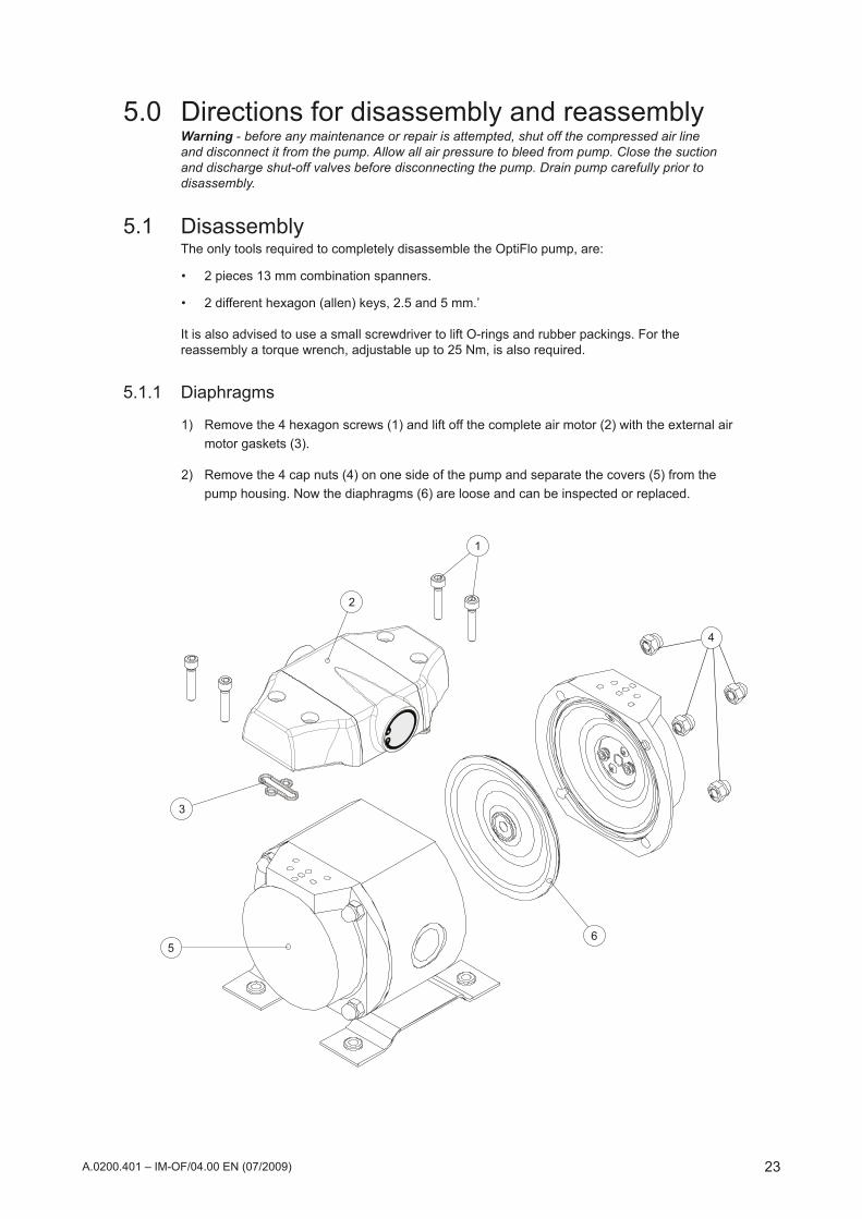
5.0 Directions for disassembly and reassemblyWarning - before any maintenance or repair is attempted, shut off the compressed air line and disconnect it from the pump. Allow all air pressure to bleed from pump. Close the suction and discharge shut-off valves before disconnecting the pump. Drain pump carefully prior to disassembly.
5.1 DisassemblyThe only tools required to completely disassemble the OptiFlo pump, are:
2 pieces 13 mm combination spanners.•
2differenthexagon(allen)keys,2.5and5mm.’•
It is also advised to use a small screwdriver to lift O-rings and rubber packings. For the reassembly a torque wrench, adjustable up to 25 Nm, is also required.
5.1.1 Diaphragms
1) Remove the 4 hexagon screws (1) and lift off the complete air motor (2) with the external air motor gaskets (3).
2) Remove the 4 cap nuts (4) on one side of the pump and separate the covers (5) from the pump housing. Now the diaphragms (6) are loose and can be inspected or replaced.

24
1
2
34
5
6
7
8
910
4
12
11
1
2
3
45
6
7
9
A.0200.401 – IM-OF/04.00 EN (07/2009)
5.1.2 Check valves, shaft, spring and shaft bushing1) Remove the shaft (1) and the spring (2) and unscrew the 2 hexagon screws (3)holding the
check valve retainers (4) and the shaft bushing (5).
2) Remove the retainers. If they are jammed use the shaft bushing (5) to push out one retainer. Turn the pump housing and push the second retainer out.
3) Check the bushing (5) and replace if worn. Replace the check valves (6, 7) if they are worn or distorted. It is recommended always to change the PTFE O-rings (8, 9) once the retainers have been removed.
5.1.3 Covers and air distribution mechanism1) Unscrew the 2 hexagon screws (1).
Lift out the washer (2) with the air outlet seal (3), plunge (7) and ball seat (6).
2) Take the O-ring out (4) and the ball (5). Remove the ball seat (6), the plunge (7) and the air outlet seal (3). Check the airoutlet seal carefully. Blow all channels (8) with compressed air.

25
3
21
3
87
1
5
4
A.0200.401 – IM-OF/04.00 EN (07/2009)
5.1.4 Air motor1) Unscrew the 4 hexagon screws (1) and remove the airmotor (2).
2) Remove the two airmotor gaskets (3).
3) Remove the CEG lockring (4) and remove the inlet insert (5).
4) RemovetheCEGlockring(7)andremovethemuffler(8).
5.2 Reassembly5.2.1 Air motor and manifolds
1) Fitthemuffler(8)andtheCEGlockringoutlet(7).
2) Fit the inlet insert (5) and the CEG lockring inlet (4)
3) Fitthetwoairmotorgasketsfirmly(3).
4) Tighten the 4 hexagon screws (1)

26
1
2
3
45
6
7
9
1
2
34
5
6
7
8
910
4
12
11
A.0200.401 – IM-OF/04.00 EN (07/2009)
5.2.2 Covers and air distribution mechanism1) Fit the O-ring (4). Put the ball (5) in place.
Fit the air outlet seal (3) to the washer (2). Fit the plunge (7) and the ball seat (6).
2) Fit the mechanism to the seat in the cover. Check that the mechanism is tight by introducing compressed air in the outer hole (9). Push the air check valve open a few times to ensure it operates properly.
5.2.3 Shaft, shaft bushing, shaft spring and check valves1) Push the shaft bushing (5) in place. Fit two new PTFE O-rings (8 and 9) in the pump housing
(10). Fit the inlet check valve (6) on one of the retainers (4). Pushtheretainerfirmlyinplacesoitsnaplocksintotheseat.
2) Turn the pump housing (10). Fit the inlet check valve (6) on the other retainer. Place the outlet check valve (7) in its seat and mount the valve support (11). Push the second retainer (4) in place.
3) Check the outlet check valve through the pump outlet. Screw the two retainers with the hexagon screws (3) and the self-locking nuts (12). Tighten the screws until the retainers are firmlyseated.Fitthespring(2)andtheshaft(1).

27
56
4
2
3
1
A.0200.401 – IM-OF/04.00 EN (07/2009)
5.2.4 Diaphragms1) Put the diaphragms (6) in the lids (5). The diaphragms are guided by the stud bolts so there
is no risk they come off place.
2) Tighten the cap nuts (4) with 22 Nm.
5.2.5 Air motor1) Fit the complete air motor (2) with air motor gaskets (3) on top of the pump housing. Tighten
the screws (1) with 10 Nm.

28
H
G
DE
F
BA
J
K
L
M
N
O
I
A.0200.401 – IM-OF/04.00 EN (07/2009)
6.0 Dimensions and weightsPump type A B D E F G H I J K L M N O Weight kg
PP / AL
OF15 14 145 2.5 64.5 130 97.6 141 101 118 147 147 123 1/4" 3/8" 2.5 / 3.7
OF30 14 145 2.5 64.5 130 97.6 141 101 118 147 147 123 3/8” 3/8" 2.5 / 3.7
OF60 14 164 2.5 74 149 97.6 141 101 118 147 147 141 3/4" 3/8" 3.6 / 4.9
OF120 14 210 2.5 97 195 97.6 184 134 148.5 178 170 184 1.1/4" 3/8" 6.9 / 9.8

29A.0200.401 – IM-OF/04.00 EN (07/2009)
7.0 Exploded views and Part lists7.1 Pump

30 A.0200.401 – IM-OF/04.00 EN (07/2009)
Pump part list (see section 7.1)
Pos. Description Version OF15 / 30, OF60, OF120
1 Pump housing, PP Pump housing, Al
PP, PXAL, AX
incl. in Pump housing PP and PX kitincl. in Pump housing Al and AX kit
2 Stud bolt all incl. in Pump housing PP/Al kits and Stud bolt kit
3 Cap nut all incl. in Pump housing PP/Al kits and Stud bolt kit
4 Lid all incl. in Cover kit
5 Diaphragm, PTFE T incl. in Diaphragm kit
6 Check valve retainer all incl. in Check valve kit with retainer
7 Check valve, inlet all incl. in Check valve kit and Check valve kit with retainer
8 PTFE, O-ring-seal all incl. in Check valve kit and Check valve kit with retainer
9 PTFE, O-ring-seal all incl. in Check valve kit and Check valve kit with retainer
10 Locknut all incl. in Check valve kit with retainer
11 Hexagon screw all incl. in Check valve kit with retainer
12 Check valve, outlet all incl. in Check valve kit and Check valve kit with retainer
13 Opening limiter all incl. in Check valve kit and Check valve kit with retainer
14 Shaft bushing all incl. in Check valve kit, Check valve kit with retainer
15 Shaft all incl. in Shaft kit
16 Shaft Spring all incl. in Shaft kit
17 Hexagon screw all incl. in Air distribution kit
18 Air outlet Washer all incl. in Air distribution kit
19 Air outlet seal all incl. in Air distribution kit
20 Air outlet Plunge all incl. in Air distribution kit
21 Air outlet Ball seat all incl. in Air distribution kit
22 O-ring all incl. in Air distribution kit
23 Air outlet Ball all incl. in Air distribution kit
24 Foot plate all incl. in Foot plate kit
25 Screw, Al housing Screw, PP housing
AL, AXPP, PX
incl. in Foot plate kit ALincl. in Foot plate kit PP
26 Rubber fot all incl. in Foot plate kit

31
28
31
33
27
32
33
2930
32
A.0200.401 – IM-OF/04.00 EN (07/2009)
Pos. Description Version OF15 / 30, OF60, OF120
27 Air motor all Incl. in Air motor kit and Air connection kit
28 Mufflerstandard all Incl.inAirmotorkitandMufflerstandardkit
29 CEG lockring inlet all Incl. in Air motor kit and Air connection kit
30 Insert Inlet all Incl. in Air motor kit and Air connection kit
31 CEG lockring outlet all Incl.inAirmotorkitandMufflerstandardkit
32 Hexagon screw all Incl. in Air motor kit
33 Airmotor gasket external all Incl. in Air motor kit and Airmotor gasket kit
7.2 Air motor spare parts (Kits see section 7.3)
32 A.0200.401 – IM-OF/04.00 EN (07/2009)
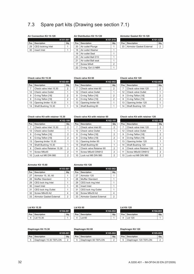
7.3 Spare part kits (Drawing see section 7.1)
Air Distribution Kit 15-120 Airmotor Gasket Kit 15-120Air Connection Kit 15-120
Check valve Kit 15.30 Check valve Kit 60 Check valve Kit 120K102-003
Pos Description Qty
7 Check valve Inlet 120 212 Check valve Outlet 19 O-ringTeflon[18] 28 O-ringTeflon[19] 2
13 Opening limiter 120 114 Shaft Bushing 120 1
K102-102Pos Description Qty
7 Check valve Inlet 120 212 Check valve Outlet 19 O-ringTeflon[18] 28 O-ringTeflon[19] 2
13 Opening limiter 120 114 Shaft Bushing 120 16 Check valve Retainer 120 211 Screw M6x50 DIN912 210 Lock nut M6 DIN 980 2
K103-002Pos Description Qty
27 Airmotor 120 128 MufflerStandard 129 CEG lock ring Inlet 130 Insert Inlet 131 CEG lock ring Outlet 132 Screw M6x30 A2 433 Airmotor Gasket External 2
K105-001Pos Description Qty
5 Diaphragm 15.30 TEFLON 2
K105-002Pos Description Qty
5 Diaphragm 60 TEFLON 2
K105-003Pos Description Qty
5 Diaphragm 120 TEFLON 2
K104-001Pos Description Qty
4 Lid 15.30 1
K104-002Pos Description Qty
4 Lid 60 1
K104-003Pos Description Qty
4 Lid 120 1
K103-001Pos Description Qty
27 Airmotor 15, 30, 60 128 MufflerStandard 129 CEG lock ring Inlet 130 Insert Inlet 131 CEG lock ring Outlet 132 Screw M6x30 A2 433 Airmotor Gasket External 2
K102-101Pos Description Qty
7 Check valve Inlet 60 212 Check valve Outlet 19 O-ringTeflon[18] 28 O-ringTeflon[19] 2
13 Opening limiter 60 114 Shaft Bushing 60 16 Check valve Retainer 60 211 Screw M6x40 DIN912 210 Lock nut M6 DIN 980 2
K102-100Pos Description Qty
7 Check valve Inlet 15.30 212 Check valve Outlet 19 O-ringTeflon[18] 28 O-ringTeflon[19] 2
13 Opening limiter 15.30 114 Shaft Bushing 15.30 16 Check valve Retainer 15.30 211 Screw M6x45 210 Lock nut M6 DIN 980 2
K101-010Pos Description Qty
20 Air outlet Plunge 118 Air outlet Washer 119 Air outlet Seal 123 Air outlet Ball D10 121 Air outlet Ball seat 117 Screw M4x8 222 O-ring 12x1,5 NBR 1
K101-001Pos Description Qty
29 CEG lockring Inlet 130 Insert Inlet 1
K101-020Pos Description Qty
33 Airmotor Gasket External 2
K102-001Pos Description Qty
7 Check valve Inlet 15.30 212 Check valve Outlet 19 O-ringTeflon[18] 28 O-ringTeflon[19] 213 Opening limiter 15.30 114 Shaft Bushing 15.30 1
K102-002Pos Description Qty
7 Check valve Inlet 60 212 Check valve Outlet 19 O-ringTeflon[18] 28 O-ringTeflon[19] 2
13 Opening limiter 60 114 Shaft Bushing 60 1
Check valve Kit with retainer 15.30
Lid Kit 15.30
Diaphragm Kit 15.30
Airmotor Kit 15.60 Airmotor Kit 120
Check valve Kit with retainer 60
Lid Kit 60
Diaphragm Kit 60
Check valve Kit with retainer 120
Lid Kit 120
Diaphragm Kit 120

33A.0200.401 – IM-OF/04.00 EN (07/2009)
Shaft Kit 15.30
Muffler Kit Standard
Studbolt Kit 15-60
Shaft Kit 60
Muffler Kit External
Studbolt Kit 120
Shaft Kit 120
Muffler Kit External with IndicatorK110-001
Pos Description Qty
31 CEG lockring Outlet 128 MufflerStandard 1
K110-002Pos Description Qty
31 CEG lockring Outlet 128 Insert Outlet 1n/a MufflerExtended 1
K110-003Pos Description Qty
31 CEG lockring Outlet 128 Insert Outlet 1n/a MufflerExtendedwindicator 1
Pump housing AL kit 15
Pump housing AX kit 15
Pump housing PP kit 15
Pump housing PX kit 15
Foot plate Kit AL 15-60
Pump housing AL kit 30
Pump housing AX kit 30
Pump housing PP kit 30
Pump housing PX kit 30
Foot plate Kit AL 120
Pump housing AL kit 60
Pump housing AX kit 60
Pump housing PP kit 60
Pump housing PX kit 60
Foot plate Kit PP 15-60
Pump housing AL kit 120
Pump housing AX kit 120
Pump housing PP kit 120
Pump housing PX kit 120
Foot plate Kit PP 120K106-001
Pos Description Qty
24 Foot plate 126 Rubber foot 425 Screw 4
K106-002Pos Description Qty
24 Foot plate 126 Rubber foot 425 Screw 4
K106-010Pos Description Qty
24 Foot plate 126 Rubber foot 425 Screw 4
K109-004Pos Description Qty
1 Pump housing AL 120 1
K109-103Pos Description Qty
1 Pump housing AX 120 1
K109-203Pos Description Qty
1 Pump housing PP 120 1
K109-303Pos Description Qty
1 Pump housing PX 120 1
K109-001Pos Description Qty
1 Pump housing AL 15 1
K109-100Pos Description Qty
1 Pump housing AX 15 1
K109-200Pos Description Qty
1 Pump housing PP 15 1
K109-300Pos Description Qty
1 Pump housing PX 15 1
K109-002Pos Description Qty
1 Pump housing AL 30 1
K109-101Pos Description Qty
1 Pump housing AX 30 1
K109-201Pos Description Qty
1 Pump housing PP 30 1
K109-301Pos Description Qty
1 Pump housing PX 30 1
K109-003Pos Description Qty
1 Pump housing AL 60 1
K109-102Pos Description Qty
1 Pump housing AX 60 1
K109-202Pos Description Qty
1 Pump housing PP 60 1
K109-302Pos Description Qty
1 Pump housing PX 60 1
K106-011Pos Description Qty
24 Foot plate 126 Rubber foot 425 Screw 4
K107-001Pos Description Qty
15 Shaft 15.30 116 Shaft Spring 15.30 1
K108-001Pos Description Qty
2 Stud Bolt 43 Cap Nuts 8
K108-002Pos Description Qty
2 Stud Bolt 43 Cap Nuts 8
K107-002Pos Description Qty
15 Shaft 60 116 Shaft Spring 60 1
K107-003Pos Description Qty
15 Shaft 120 116 Shaft Spring 120 1
7.3 Sparepartkits(Drawingseesection7.1)cont’d

34 A.0200.401 – IM-OF/04.00 EN (07/2009)
8.0 Trouble shooting For drawings and positions see chapter 7.0.
Pump will not run •Checkthereissufficientairpressure.
•Checkthattheemergencystopvalveisopen.
•Checkinletairfilterandmufflerfordebris.
•Checkthatthesuction-anddischargelinesareopen.
•Removethemuffler/airoutlethoseandcheckthattheairmotor pivot moves freely.
•Openthepumpandcheckthediaphragms,airoutletseals (pos 19) and air check valves (pos 20-23).
•Checkthattheshaft(15)movesfreely.
•Checkthepivotingvalvesbearing–sealmaybewornout.Pump does not prime •Checkthatthesuctionanddischargelinesareopen.
•Checkthatallsuctionconnectionsareairtight.
•Increasethestrokingspeed.
•Checkthatthecovernutsaretightened.
•Checkthediaphragms(pos5).
•Checkthattheinletfluidcheckvalves(pos7and12)sealtothe seats.
•Replacetheshaftbushing(pos14)ifitisworn.Erratic pump action/heavy pulsation •Checkthediaphragms(pos5).
•Checkthattheairmotorpivot(pos31)movesfreelyandthatthe rubber seals (pos 31 and 34) are intact.
•Checkthefluidcheckvalves(pos7and12).
•Checkthattheshaftspring(16)isundamaged.
•Checktheairoutletseals(pos19).Pumprunsbutflowisreduced •Checkthatthesuctionanddischargelinesareopen.
•Checkthatallsuctionconnectionsareairtight.
•Checkforpossiblecavitation.Slowpumpspeeddowntomatchtheviscosity(thickness)ofthefluid.
•Openthepumpandcheckthediaphragms(pos5)andthefluidcheckvalves(pos12and7).
•Iftheshaftbushing(pos14)isworntheinternalslipincreasesandflowdecreases-changethebushing.
•Checkthattheairchannelsarefreefromdebris.Fluid comes out of the air exhaust •Checkfordiaphragmrupture.Airbubblesinthefluid •Checkthatallsuctionconnectionsareairtight.
•Checkfordiaphragmrupture.


SPX Process Equipment BE NVEvenbroekveld 2-6BE-9420 Erpe-Mere, BelgiumPhone: +32 (0)53 60 27 15 Fax: +32 (0)53 60 27 01E-mail: jp-industry.be@processequipment.spx.comFormoreinformationaboutourworldwidelocations,approvals,certifications,andlocalrepresentatives,pleasevisit www.johnson-pump.com and spxpe.com.
SPX Corporation reserves the right to incorporate our latest design and material changes without notice or obligation.Design features, materials of construction and dimensional data, as described in this bulletin, are provided for your information only andshouldnotberelieduponunlessconfirmedinwriting.
Copyright © 2000, 2009 SPX Corporation
Your local contact: