instruction manual pressure-resistant, … explosion-proof motor ......
TRANSCRIPT
PRESSURE-RESISTANT, EXPLOSION-PROOF MOTOR DRIVING INVERTERIN
STRU
CTIO
N M
AN
UAL
FR-B, B3
PRESSURE-RESISTANT,EXPLOSION-PROOF MOTOR DRIVING INVERTER
FR-B, B3INSTRUCTION MANUAL
OUTLINE
PARAMETERS
SPECIFICATIONS
INSTALLATIONAND WIRING
PROTECTIVEFUNCTIONS
Chapter 6
OPTIONS Chapter 7
Chapter 5
Chapter 4
Chapter 3
Chapter 2
Chapter 1
OPERATION/ CONTROL
IB (NA) 0600011-B (0311) MEE Printed in Japan Specifications subject to change without notice.
HEAD OFFICE:MITSUBISHI DENKI BLDG MARUNOUCHI TOKYO 100-8310
FR-B-750 to 45K(200V CLASS)FR-B-750 to 55K(400V CLASS)
(A500 SPECIFICATIONS)
Variable torque type
Running pressure-resistant, explosion-proof
motors under V/F control
Constant torque type (Non-low acoustic noise or low acoustic noise)
FR-B3-(H)400 to 37KFR-B3-N(H)400 to 37KRunning pressure-resistant, explosion-
proof motors under advanced magnetic
flux vector control
(Setting of offline auto tuning is required.
Refer to Chapter 3.)
A - 1
Thank you for choosing this Mitsubishi Pressure-Resistant, Explosion-Proof Motor DrivingInverter.This instruction manual gives handling information and precautions for use of thisequipment.Incorrect handling might cause an unexpected fault. Before using the inverter, please readthis manual carefully to use the equipment to its optimum.Please forward this manual to the end user.
This section is specifically about safety mattersDo not attempt to install, operate, maintain or inspect the inverter until you have read through thisinstruction manual and appended documents carefully and can use the equipment correctly.Do not use the inverter until you have a full knowledge of the equipment, safety information andinstructions.In this instruction manual, the safety instruction levels are classified into “WARNING” and “CAUTION”.
Assumes that incorrect handling may cause hazardous conditions, resulting indeath or severe injury.
Assumes that incorrect handling may cause hazardous conditions, resulting inmedium or slight injury, or may cause physical damage only.
Note that the CAUTION level may lead to a serious consequence according to conditions. Please followthe instructions of both levels because they are important to personnel safety.
CAUTION
WARNING
A - 2
SAFETY INSTRUCTIONS
1. Electric Shock PreventionWARNING
While power is on or when the inverter is running, do not open the front cover. You may get an electricshock.
Do not run the inverter with the front cover removed. Otherwise, you may access the exposed high-voltage terminals or the charging part of the circuitry and get an electric shock.
If power is off, do not remove the front cover except for wiring or periodic inspection. You may accessthe charged inverter circuits and get an electric shock.
Before starting wiring or inspection, switch power off, wait for more than at least 10 minutes and checkfor the presence of any residual voltage with a meter (check chapter 2 for further details.) etc.
Earth the inverter. Any person who is involved in the wiring or inspection of this equipment should be fully competent to do
the work. Always install the inverter before wiring. Otherwise, you may get an electric shock or be injured. Operate the switches with dry hands to prevent an electric shock. Do not subject the cables to scratches, excessive stress, heavy loads or pinching. Otherwise, you may
get an electric shock. Do not change the cooling fan while power is on. To do so will invite a hazardous condition.
2. Fire PreventionCAUTION
Mount the inverter on an incombustible surface. Installing the inverter directly on or near a combustiblesurface could lead to a fire.
If the inverter has become faulty, switch off the inverter power. A continuous flow of large current couldcause a fire.
Do not connect a resistor directly to the DC terminals P, N. This could cause a fire.
3. Injury PreventionCAUTION
Apply only the voltage specified in the instruction manual to each terminal to prevent damage etc. Ensure that the cables are connected to the correct terminals. Otherwise, damage etc. may occur. Always make sure that polarity is correct to prevent damage etc. After the inverter has been operating for a relativly long period of time, do not touch the inverter as it
may be hot and you may get burnt.
A - 3
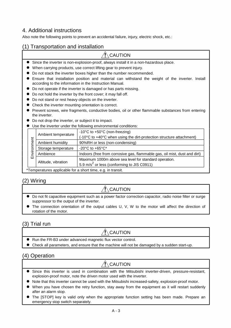
4. Additional instructionsAlso note the following points to prevent an accidental failure, injury, electric shock, etc.:
(1) Transportation and installationCAUTION
Since the inverter is non-explosion-proof, always install it in a non-hazardous place.When carrying products, use correct lifting gear to prevent injury.
Do not stack the inverter boxes higher than the number recommended. Ensure that installation position and material can withstand the weight of the inverter. Install
according to the information in the Instruction Manual. Do not operate if the inverter is damaged or has parts missing. Do not hold the inverter by the front cover; it may fall off. Do not stand or rest heavy objects on the inverter. Check the inverter mounting orientation is correct. Prevent screws, wire fragments, conductive bodies, oil or other flammable substances from entering
the inverter. Do not drop the inverter, or subject it to impact. Use the inverter under the following environmental conditions:
Ambient temperature -10°C to +50°C (non-freezing)(-10°C to +40°C when using the dirt-protection structure attachment)
Ambient humidity 90%RH or less (non-condensing)Storage temperature -20°C to +65°C*Ambience Indoors (free from corrosive gas, flammable gas, oil mist, dust and dirt)
Envi
ronm
ent
Altitude, vibration Maximum 1000m above sea level for standard operation.5.9 m/s2 or less (conforming to JIS C0911)
*Temperatures applicable for a short time, e.g. in transit.
(2) WiringCAUTION
Do not fit capacitive equipment such as a power factor correction capacitor, radio noise filter or surgesuppressor to the output of the inverter.
The connection orientation of the output cables U, V, W to the motor will affect the direction ofrotation of the motor.
(3) Trial runCAUTION
Run the FR-B3 under advanced magnetic flux vector control. Check all parameters, and ensure that the machine will not be damaged by a sudden start-up.
(4) OperationCAUTION
Since this inverter is used in combination with the Mitsubishi inverter-driven, pressure-resistant,explosion-proof motor, note the driven motor used with the inverter.
Note that this inverter cannot be used with the Mitsubishi increased-safety, explosion-proof motor. When you have chosen the retry function, stay away from the equipment as it will restart suddenly
after an alarm stop. The [STOP] key is valid only when the appropriate function setting has been made. Prepare an
emergency stop switch separately.
A - 4
CAUTION Make sure that the start signal is off before resetting the inverter alarm. A failure to do so may restart
the motor suddenly. The load used should be a three-phase induction motor only. Connection of any other electrical
equipment to the inverter output may damage the equipment. Do not modify the inverter. The electronic overcurrent protection does not guarantee protection of the motor from overheating. Do not use a magnetic contactor on the inverter input for frequent starting/stopping of the inverter. Use a noise filter to reduce the effect of electromagnetic interference. Otherwise nearby electronic
equipment may be affected. Take measures to suppress harmonics. Otherwise power harmonics from the inverter may
heat/damage the power capacitor and generator. When parameter clear or all clear is performed, each parameter returns to the factory setting. Re-set
the required parameters before starting operation. The inverter can be easily set for high-speed operation. Before changing its setting, examine the
performance of the motor and machine. In addition to the inverter's holding function, install a holding device to ensure safety. Before running an inverter which had been stored for a long period, always perform inspection and
test operation.
(5) Emergency stopCAUTION
Provide a safety backup such as an emergency brake which will prevent the machine and equipmentfrom hazardous conditions if the inverter fails.
(6) Maintenance, inspection and parts replacementCAUTION
Do not carry out a megger (insulation resistance) test on the control circuit of the inverter.
(7) Disposing of the inverterCAUTION
Treat as industrial waste.
(8) General instructionsMany of the diagrams and drawings in this instruction manual show the inverter without a cover, or partiallyopen. Never run the inverter like this. Always replace the cover and follow this instruction manual whenoperating the inverter.
CONTENTS
I
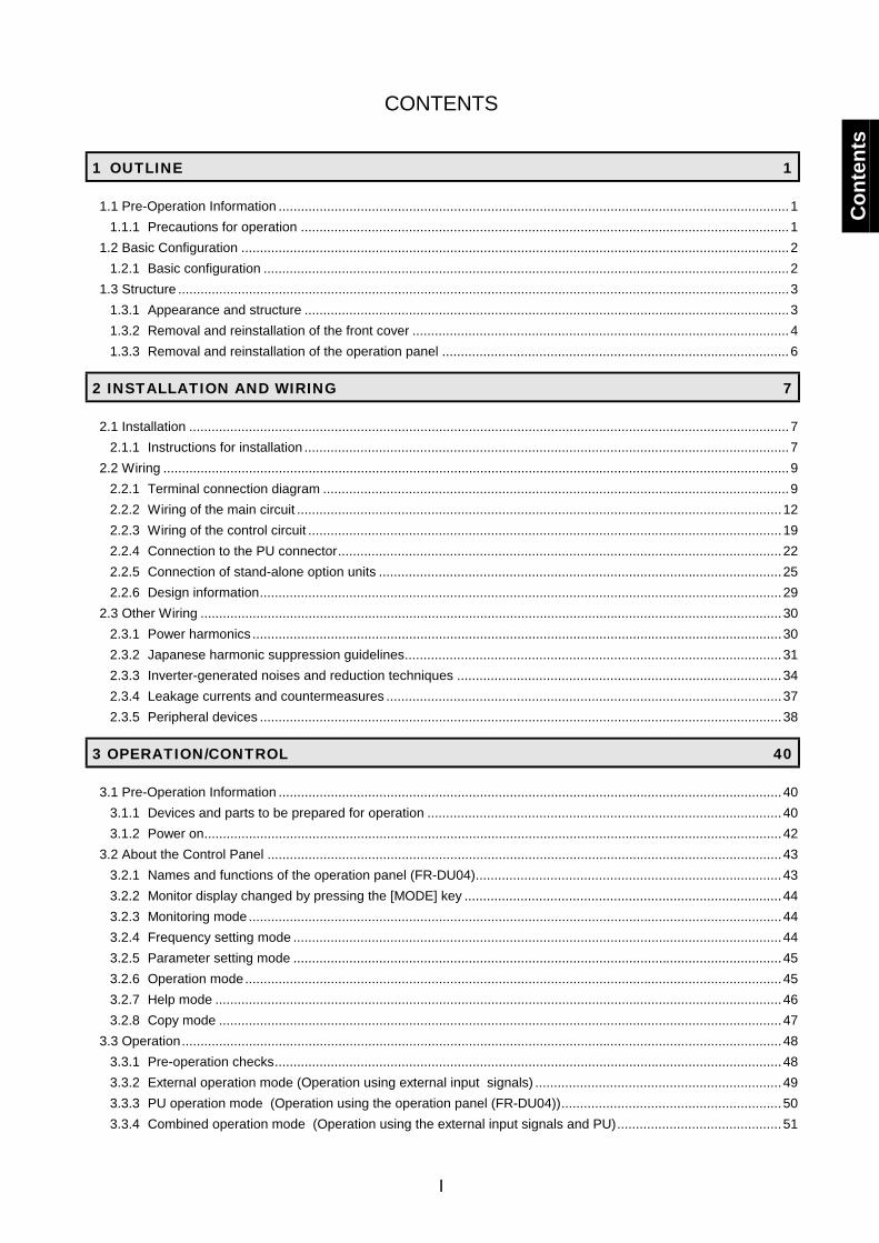
1 OUTLINE 1
1.1 Pre-Operation Information .........................................................................................................................................11.1.1 Precautions for operation ...................................................................................................................................1
1.2 Basic Configuration ...................................................................................................................................................21.2.1 Basic configuration .............................................................................................................................................2
1.3 Structure ....................................................................................................................................................................31.3.1 Appearance and structure ..................................................................................................................................31.3.2 Removal and reinstallation of the front cover .....................................................................................................41.3.3 Removal and reinstallation of the operation panel .............................................................................................6
2 INSTALLATION AND WIRING 7
2.1 Installation .................................................................................................................................................................72.1.1 Instructions for installation ..................................................................................................................................7
2.2 Wiring ........................................................................................................................................................................92.2.1 Terminal connection diagram .............................................................................................................................92.2.2 Wiring of the main circuit ..................................................................................................................................122.2.3 Wiring of the control circuit ...............................................................................................................................192.2.4 Connection to the PU connector.......................................................................................................................222.2.5 Connection of stand-alone option units ............................................................................................................252.2.6 Design information............................................................................................................................................29
2.3 Other Wiring ............................................................................................................................................................302.3.1 Power harmonics ..............................................................................................................................................302.3.2 Japanese harmonic suppression guidelines.....................................................................................................312.3.3 Inverter-generated noises and reduction techniques .......................................................................................342.3.4 Leakage currents and countermeasures ..........................................................................................................372.3.5 Peripheral devices ............................................................................................................................................38
3 OPERATION/CONTROL 40
3.1 Pre-Operation Information .......................................................................................................................................403.1.1 Devices and parts to be prepared for operation ...............................................................................................403.1.2 Power on...........................................................................................................................................................42
3.2 About the Control Panel ..........................................................................................................................................433.2.1 Names and functions of the operation panel (FR-DU04)..................................................................................433.2.2 Monitor display changed by pressing the [MODE] key .....................................................................................443.2.3 Monitoring mode...............................................................................................................................................443.2.4 Frequency setting mode ...................................................................................................................................443.2.5 Parameter setting mode ...................................................................................................................................453.2.6 Operation mode................................................................................................................................................453.2.7 Help mode ........................................................................................................................................................463.2.8 Copy mode .......................................................................................................................................................47
3.3 Operation.................................................................................................................................................................483.3.1 Pre-operation checks........................................................................................................................................483.3.2 External operation mode (Operation using external input signals) ..................................................................493.3.3 PU operation mode (Operation using the operation panel (FR-DU04))...........................................................503.3.4 Combined operation mode (Operation using the external input signals and PU)............................................51
Con
tent
s
II
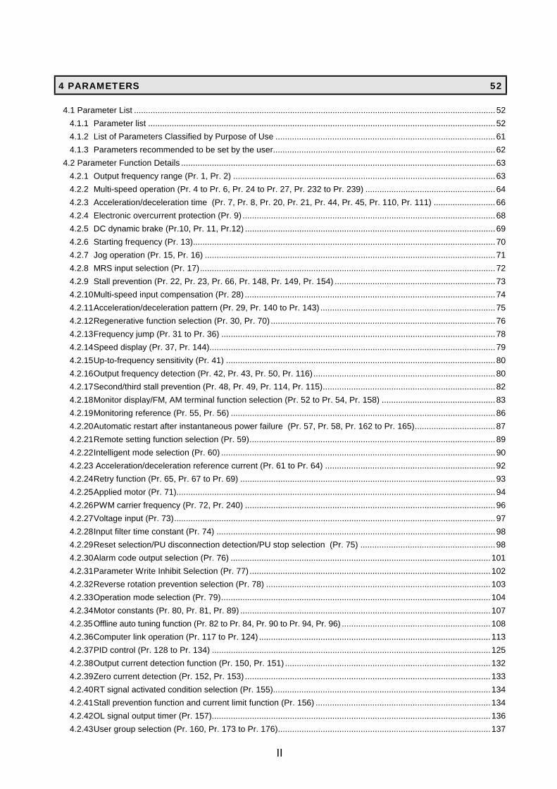
4 PARAMETERS 52
4.1 Parameter List .........................................................................................................................................................524.1.1 Parameter list ...................................................................................................................................................524.1.2 List of Parameters Classified by Purpose of Use .............................................................................................614.1.3 Parameters recommended to be set by the user..............................................................................................62
4.2 Parameter Function Details .....................................................................................................................................634.2.1 Output frequency range (Pr. 1, Pr. 2) ...............................................................................................................634.2.2 Multi-speed operation (Pr. 4 to Pr. 6, Pr. 24 to Pr. 27, Pr. 232 to Pr. 239) .......................................................644.2.3 Acceleration/deceleration time (Pr. 7, Pr. 8, Pr. 20, Pr. 21, Pr. 44, Pr. 45, Pr. 110, Pr. 111) ..........................664.2.4 Electronic overcurrent protection (Pr. 9) ...........................................................................................................684.2.5 DC dynamic brake (Pr.10, Pr. 11, Pr.12) ..........................................................................................................694.2.6 Starting frequency (Pr. 13)................................................................................................................................704.2.7 Jog operation (Pr. 15, Pr. 16) ...........................................................................................................................714.2.8 MRS input selection (Pr. 17).............................................................................................................................724.2.9 Stall prevention (Pr. 22, Pr. 23, Pr. 66, Pr. 148, Pr. 149, Pr. 154) ....................................................................734.2.10Multi-speed input compensation (Pr. 28) ..........................................................................................................744.2.11Acceleration/deceleration pattern (Pr. 29, Pr. 140 to Pr. 143) ..........................................................................754.2.12Regenerative function selection (Pr. 30, Pr. 70) ...............................................................................................764.2.13Frequency jump (Pr. 31 to Pr. 36) ....................................................................................................................784.2.14Speed display (Pr. 37, Pr. 144).........................................................................................................................794.2.15Up-to-frequency sensitivity (Pr. 41) ..................................................................................................................804.2.16Output frequency detection (Pr. 42, Pr. 43, Pr. 50, Pr. 116).............................................................................804.2.17Second/third stall prevention (Pr. 48, Pr. 49, Pr. 114, Pr. 115).........................................................................824.2.18Monitor display/FM, AM terminal function selection (Pr. 52 to Pr. 54, Pr. 158) ................................................834.2.19Monitoring reference (Pr. 55, Pr. 56) ................................................................................................................864.2.20Automatic restart after instantaneous power failure (Pr. 57, Pr. 58, Pr. 162 to Pr. 165)..................................874.2.21Remote setting function selection (Pr. 59)........................................................................................................894.2.22Intelligent mode selection (Pr. 60) ....................................................................................................................904.2.23 Acceleration/deceleration reference current (Pr. 61 to Pr. 64) ........................................................................924.2.24Retry function (Pr. 65, Pr. 67 to Pr. 69) ............................................................................................................934.2.25Applied motor (Pr. 71).......................................................................................................................................944.2.26PWM carrier frequency (Pr. 72, Pr. 240) ..........................................................................................................964.2.27Voltage input (Pr. 73)........................................................................................................................................974.2.28Input filter time constant (Pr. 74) ......................................................................................................................984.2.29Reset selection/PU disconnection detection/PU stop selection (Pr. 75) .........................................................984.2.30Alarm code output selection (Pr. 76) ..............................................................................................................1014.2.31Parameter Write Inhibit Selection (Pr. 77) ......................................................................................................1024.2.32Reverse rotation prevention selection (Pr. 78) ...............................................................................................1034.2.33Operation mode selection (Pr. 79)..................................................................................................................1044.2.34Motor constants (Pr. 80, Pr. 81, Pr. 89) ..........................................................................................................1074.2.35Offline auto tuning function (Pr. 82 to Pr. 84, Pr. 90 to Pr. 94, Pr. 96) ...............................................................1084.2.36Computer link operation (Pr. 117 to Pr. 124) ..................................................................................................1134.2.37PID control (Pr. 128 to Pr. 134) ......................................................................................................................1254.2.38Output current detection function (Pr. 150, Pr. 151) .......................................................................................1324.2.39Zero current detection (Pr. 152, Pr. 153) ........................................................................................................1334.2.40RT signal activated condition selection (Pr. 155)............................................................................................1344.2.41Stall prevention function and current limit function (Pr. 156) ..........................................................................1344.2.42OL signal output timer (Pr. 157)......................................................................................................................1364.2.43User group selection (Pr. 160, Pr. 173 to Pr. 176)..........................................................................................137
III
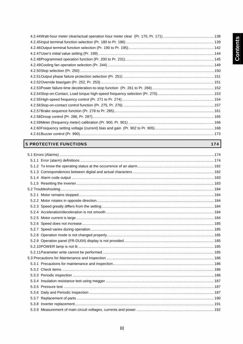
4.2.44Watt-hour meter clear/actual operation hour meter clear (Pr. 170, Pr. 171) .................................................1384.2.45Input terminal function selection (Pr. 180 to Pr. 186) .....................................................................................1394.2.46Output terminal function selection (Pr. 190 to Pr. 195)...................................................................................1424.2.47User's initial value setting (Pr. 199) ................................................................................................................1444.2.48Programmed operation function (Pr. 200 to Pr. 231)......................................................................................1454.2.49Cooling fan operation selection (Pr. 244) .......................................................................................................1494.2.50Stop selection (Pr. 250) ..................................................................................................................................1504.2.51Output phase failure protection selection (Pr. 251) ........................................................................................1514.2.52Override bias/gain (Pr. 252, Pr. 253) ..............................................................................................................1514.2.53Power failure-time deceleration-to-stop function (Pr. 261 to Pr. 266)............................................................1524.2.54Stop-on-Contact, Load torque high-speed frequency selection (Pr. 270).......................................................1534.2.55High-speed frequency control (Pr. 271 to Pr. 274) .........................................................................................1544.2.56Stop-on-contact control function (Pr. 275, Pr. 276) ........................................................................................1574.2.57Brake sequence function (Pr. 278 to Pr. 285).................................................................................................1614.2.58Droop control (Pr. 286, Pr. 287)......................................................................................................................1654.2.59Meter (frequency meter) calibration (Pr. 900, Pr. 901) ...................................................................................1664.2.60Frequency setting voltage (current) bias and gain (Pr. 902 to Pr. 905) .........................................................1684.2.61Buzzer control (Pr. 990)..................................................................................................................................173
5 PROTECTIVE FUNCTIONS 174
5.1 Errors (Alarms) ......................................................................................................................................................1745.1.1 Error (alarm) definitions ..................................................................................................................................1745.1.2 To know the operating status at the occurrence of an alarm..........................................................................1825.1.3 Correspondences between digital and actual characters ...............................................................................1825.1.4 Alarm code output ..........................................................................................................................................1835.1.5 Resetting the inverter......................................................................................................................................183
5.2 Troubleshooting.....................................................................................................................................................1845.2.1 Motor remains stopped...................................................................................................................................1845.2.2 Motor rotates in opposite direction..................................................................................................................1845.2.3 Speed greatly differs from the setting.............................................................................................................1845.2.4 Acceleration/deceleration is not smooth.........................................................................................................1845.2.5 Motor current is large......................................................................................................................................1845.2.6 Speed does not increase................................................................................................................................1855.2.7 Speed varies during operation........................................................................................................................1855.2.8 Operation mode is not changed properly........................................................................................................1855.2.9 Operation panel (FR-DU04) display is not provided .......................................................................................1855.2.10POWER lamp is not lit ....................................................................................................................................1855.2.11Parameter write cannot be performed ............................................................................................................185
5.3 Precautions for Maintenance and Inspection ........................................................................................................1865.3.1 Precautions for maintenance and inspection..................................................................................................1865.3.2 Check items....................................................................................................................................................1865.3.3 Periodic inspection .........................................................................................................................................1865.3.4 Insulation resistance test using megger .........................................................................................................1875.3.5 Pressure test ..................................................................................................................................................1875.3.6 Daily and Periodic Inspection .........................................................................................................................1875.3.7 Replacement of parts .....................................................................................................................................1905.3.8 Inverter replacement.......................................................................................................................................1915.3.9 Measurement of main circuit voltages, currents and power ...........................................................................192
Con
tent
s
IV
6 SPECIFICATIONS 194
6.1 Standard Specifications.........................................................................................................................................1946.1.1 Model specifications .......................................................................................................................................1946.1.2 Specifications common to the FR-B series.....................................................................................................1966.1.3 Model specifications .......................................................................................................................................1976.1.4 Specifications common to the FR-B3 series...................................................................................................1996.1.5 Outline drawings .............................................................................................................................................201
7 OPTIONS 205
7.1 Option List .............................................................................................................................................................2057.1.1 Stand-alone options........................................................................................................................................2057.1.2 Inboard dedicated options ..............................................................................................................................207
APPENDICES 208
Appendix 1 Data Code List ..........................................................................................................................................208
1
CHAPTER 1OUTLINE
This chapter gives information on the basic "outline" of thisproduct.Always read the instructions in this chapter before using theequipment.
1.1 Pre-Operation Information........................................1 1.2 Basic Configuration..................................................2 1.3 Structure ..................................................................3
<Abbreviations> DUOperation panel (FR-DU04)
PUOperation panel (FR-DU04) and parameter unit (FR-PU04)
InverterMitsubishi pressure-resistant, explosion-proof motor drivinginverter FR-B, B3 series
Pr.Parameter number
PU operationOperation using the PU (FR-DU04/FR-PU04)
External operationOperation using the control circuit signals
Combined operationOperation using both the PU (FR-DU04/FR-PU04)and external operation
FR-B (A200E)Mitsubishi pressure-resistant, explosion-proof motor drivinginverter FR-B (A200E specifications) series
Chapter 1
Chapter 2
Chapter 3
Chapter 4
Chapter 5
Chapter 6
Chapter 7
1.1 Pre-Operation InformationOUTLINE
1
1 OUTLINE1.1 Pre-Operation Information
1.1.1 Precautions for operationIncorrect handling might cause the inverter to operate improperly, its life to be reduced considerably, or at theworst, the inverter to be damaged. Handle the inverter properly in accordance with the information in eachsection as well as the precautions and instructions of this manual to use it correctly.This manual is written for the FR-B, B3 series pressure-resistant, explosion-proof motor driving inverters.For handling information on the parameter unit (FR-PU04), inboard options, stand-alone options, etc., refer tothe corresponding manuals.
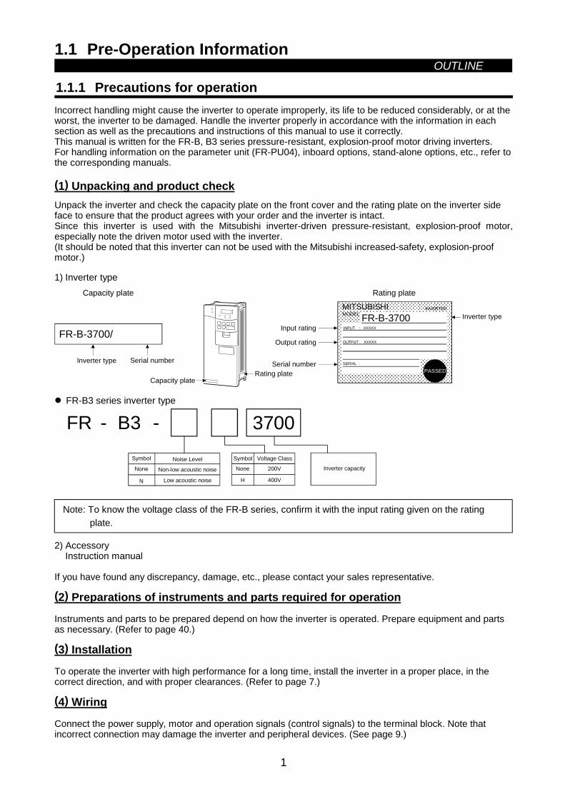
(1) Unpacking and product checkUnpack the inverter and check the capacity plate on the front cover and the rating plate on the inverter sideface to ensure that the product agrees with your order and the inverter is intact.Since this inverter is used with the Mitsubishi inverter-driven pressure-resistant, explosion-proof motor,especially note the driven motor used with the inverter.(It should be noted that this inverter can not be used with the Mitsubishi increased-safety, explosion-proofmotor.)
1) Inverter type
FR-B-3700/
MITSUBISHIMODEL
INVERTER
FR-B-3700 INPUT :
OUTPUT :
SERIAL :
XXXXX
XXXXX
PASSED
Capacity plate
Inverter type Serial number
Capacity plateRating plate
Rating plate
Input rating
Output rating
Serial number
Inverter type
FR-B3 series inverter type
Low acoustic noise
-FR B3 -
200V
400VH
3700
N
Inverter capacity
Symbol Noise LevelNone Non-low acoustic noise
Symbol Voltage Class
None
Note: To know the voltage class of the FR-B series, confirm it with the input rating given on the ratingplate.
2) AccessoryInstruction manual
If you have found any discrepancy, damage, etc., please contact your sales representative.
(2) Preparations of instruments and parts required for operation
Instruments and parts to be prepared depend on how the inverter is operated. Prepare equipment and partsas necessary. (Refer to page 40.)
(3) Installation
To operate the inverter with high performance for a long time, install the inverter in a proper place, in thecorrect direction, and with proper clearances. (Refer to page 7.)
(4) Wiring
Connect the power supply, motor and operation signals (control signals) to the terminal block. Note thatincorrect connection may damage the inverter and peripheral devices. (See page 9.)
1.2 Basic ConfigurationOUTLINE
2
1.2 Basic Configuration
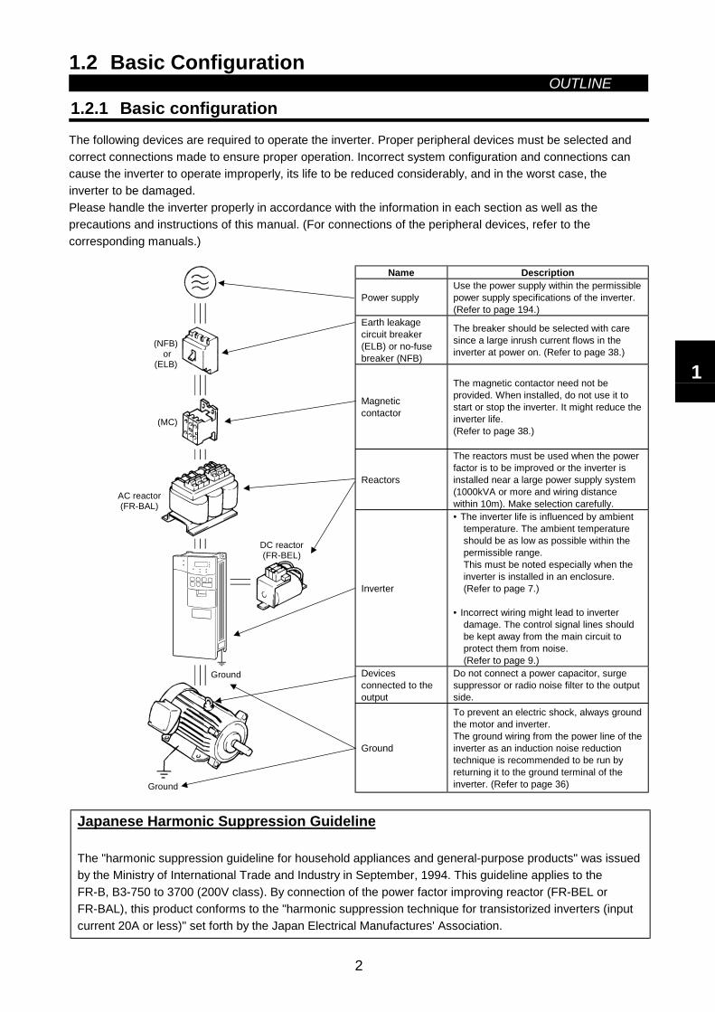
1.2.1 Basic configurationThe following devices are required to operate the inverter. Proper peripheral devices must be selected andcorrect connections made to ensure proper operation. Incorrect system configuration and connections cancause the inverter to operate improperly, its life to be reduced considerably, and in the worst case, theinverter to be damaged.Please handle the inverter properly in accordance with the information in each section as well as theprecautions and instructions of this manual. (For connections of the peripheral devices, refer to thecorresponding manuals.)
Name Description
Power supplyUse the power supply within the permissiblepower supply specifications of the inverter.(Refer to page 194.)
Earth leakagecircuit breaker(ELB) or no-fusebreaker (NFB)
The breaker should be selected with caresince a large inrush current flows in theinverter at power on. (Refer to page 38.)
Magneticcontactor
The magnetic contactor need not beprovided. When installed, do not use it tostart or stop the inverter. It might reduce theinverter life.(Refer to page 38.)
Reactors
The reactors must be used when the powerfactor is to be improved or the inverter isinstalled near a large power supply system(1000kVA or more and wiring distancewithin 10m). Make selection carefully.
Inverter
• The inverter life is influenced by ambienttemperature. The ambient temperatureshould be as low as possible within thepermissible range.This must be noted especially when theinverter is installed in an enclosure.(Refer to page 7.)
• Incorrect wiring might lead to inverterdamage. The control signal lines shouldbe kept away from the main circuit toprotect them from noise.(Refer to page 9.)
Devicesconnected to theoutput
Do not connect a power capacitor, surgesuppressor or radio noise filter to the outputside.
(MC)
Ground
DC reactor(FR-BEL)
Ground
(NFB) or
(ELB)
AC reactor(FR-BAL)
Ground
To prevent an electric shock, always groundthe motor and inverter.The ground wiring from the power line of theinverter as an induction noise reductiontechnique is recommended to be run byreturning it to the ground terminal of theinverter. (Refer to page 36)
Japanese Harmonic Suppression Guideline
The "harmonic suppression guideline for household appliances and general-purpose products" was issuedby the Ministry of International Trade and Industry in September, 1994. This guideline applies to theFR-B, B3-750 to 3700 (200V class). By connection of the power factor improving reactor (FR-BEL orFR-BAL), this product conforms to the "harmonic suppression technique for transistorized inverters (inputcurrent 20A or less)" set forth by the Japan Electrical Manufactures' Association.
1
1.3 StructureOUTLINE
3
1.3 Structure
1.3.1 Appearance and structure
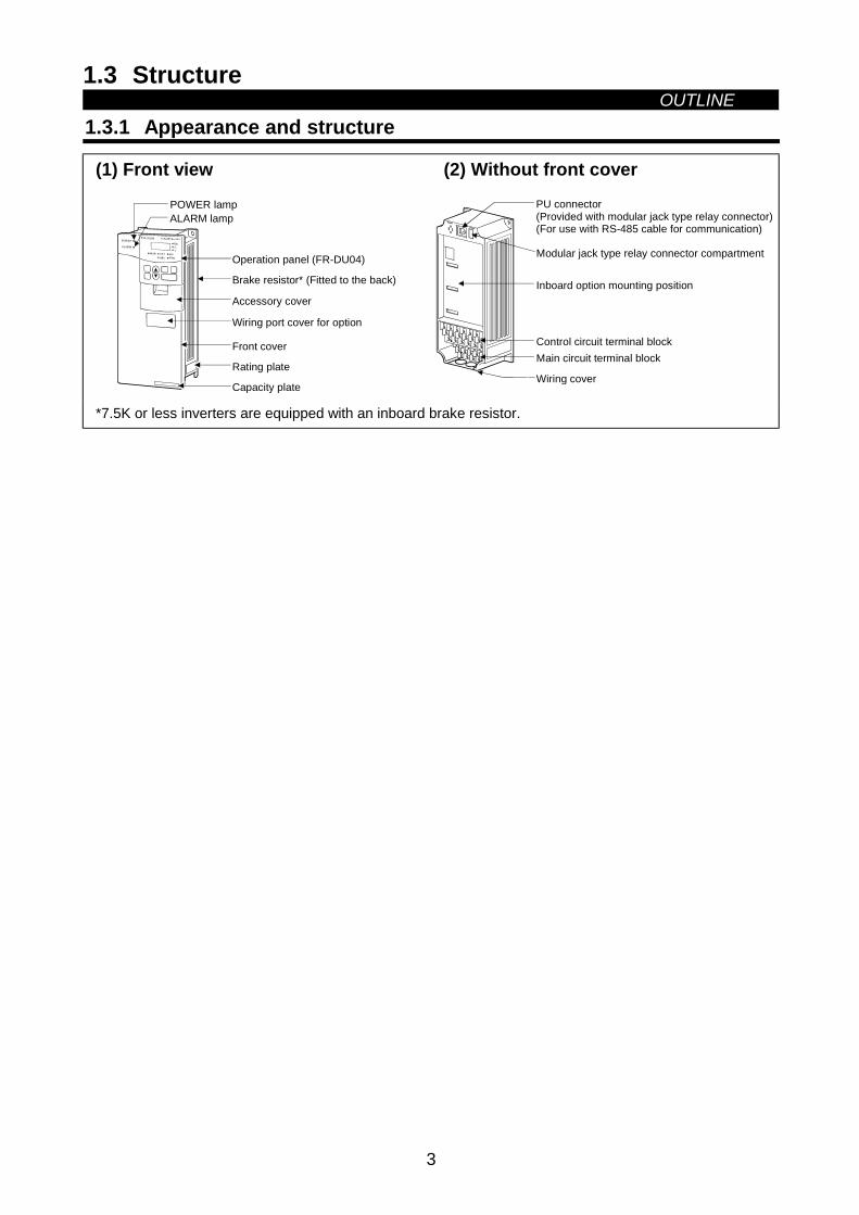
(1) Front view
POWER lampALARM lamp
Operation panel (FR-DU04)
Brake resistor* (Fitted to the back)
Accessory cover
Wiring port cover for option
Front cover
Rating plate
Capacity plate
(2) Without front cover
Wiring cover
PU connector(Provided with modular jack type relay connector)(For use with RS-485 cable for communication)
Modular jack type relay connector compartment
Inboard option mounting position
Control circuit terminal blockMain circuit terminal block
*7.5K or less inverters are equipped with an inboard brake resistor.
OUTLINE
4
1.3.2 Removal and reinstallation of the front cover
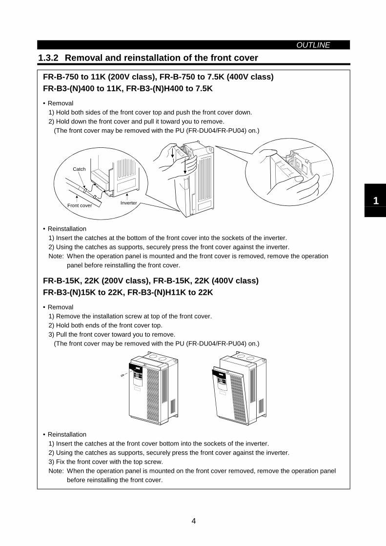
FR-B-750 to 11K (200V class), FR-B-750 to 7.5K (400V class)FR-B3-(N)400 to 11K, FR-B3-(N)H400 to 7.5K• Removal
1) Hold both sides of the front cover top and push the front cover down.2) Hold down the front cover and pull it toward you to remove. (The front cover may be removed with the PU (FR-DU04/FR-PU04) on.)
Front cover Inverter
Catch
• Reinstallation1) Insert the catches at the bottom of the front cover into the sockets of the inverter.2) Using the catches as supports, securely press the front cover against the inverter.Note: When the operation panel is mounted and the front cover is removed, remove the operation
panel before reinstalling the front cover.
FR-B-15K, 22K (200V class), FR-B-15K, 22K (400V class)FR-B3-(N)15K to 22K, FR-B3-(N)H11K to 22K• Removal
1) Remove the installation screw at top of the front cover.2) Hold both ends of the front cover top.3) Pull the front cover toward you to remove. (The front cover may be removed with the PU (FR-DU04/FR-PU04) on.)
• Reinstallation1) Insert the catches at the front cover bottom into the sockets of the inverter.2) Using the catches as supports, securely press the front cover against the inverter.3) Fix the front cover with the top screw.Note: When the operation panel is mounted on the front cover removed, remove the operation panel
before reinstalling the front cover.
1
OUTLINE
5
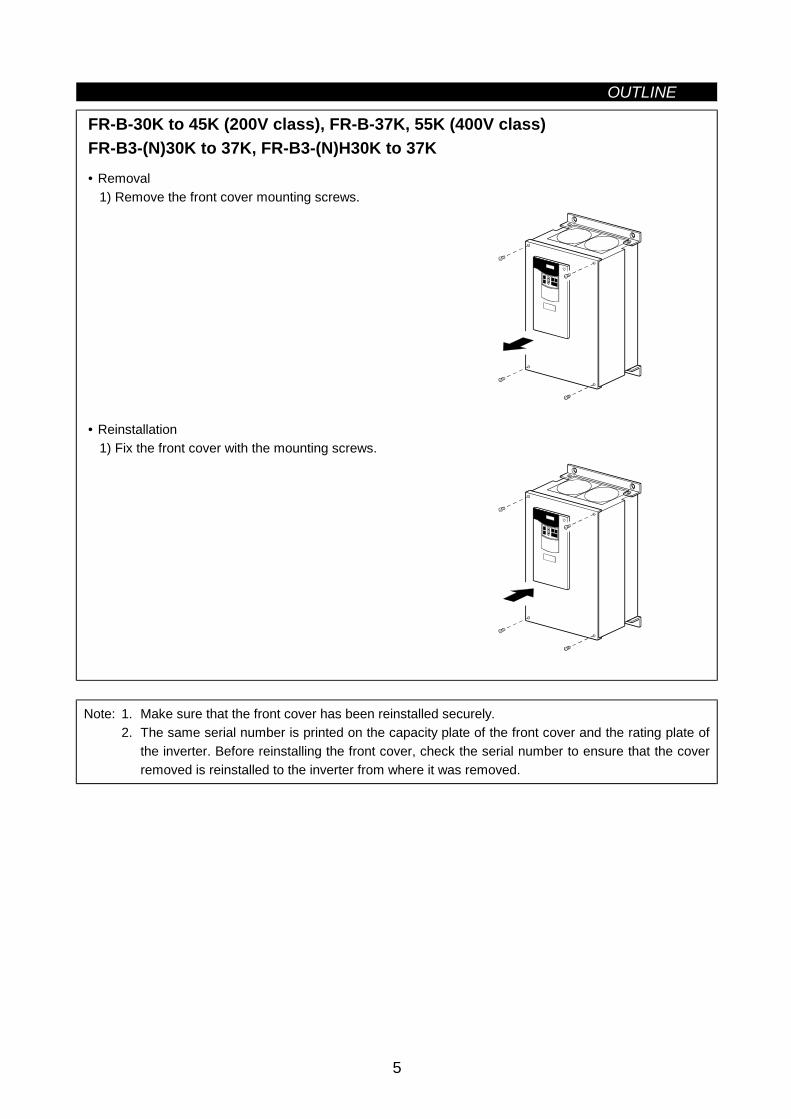
FR-B-30K to 45K (200V class), FR-B-37K, 55K (400V class)FR-B3-(N)30K to 37K, FR-B3-(N)H30K to 37K• Removal
1) Remove the front cover mounting screws.
• Reinstallation1) Fix the front cover with the mounting screws.
Note: 1. Make sure that the front cover has been reinstalled securely.2. The same serial number is printed on the capacity plate of the front cover and the rating plate of
the inverter. Before reinstalling the front cover, check the serial number to ensure that the coverremoved is reinstalled to the inverter from where it was removed.
OUTLINE
6
1.3.3 Removal and reinstallation of the operation panel
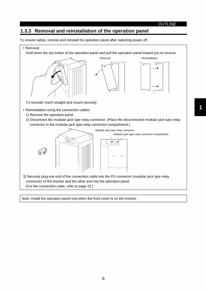
To ensure safety, remove and reinstall the operation panel after switching power off.
• RemovalHold down the top button of the operation panel and pull the operation panel toward you to remove.
Removal Reinstallation
To reinstall, insert straight and mount securely.
• Reinstallation using the connection cables1) Remove the operation panel.2) Disconnect the modular jack type relay connector. (Place the disconnected modular jack type relay connector in the modular jack type relay connector compartment.)
Modular jack type relay connector compartmentModular jack type relay connector
3) Securely plug one end of the connection cable into the PU connector (modular jack type relayconnector) of the inverter and the other end into the operation panel.(For the connection cable, refer to page 22.)
Note: Install the operation panel only when the front cover is on the inverter.
1

MEMO
2
CHAPTER 2INSTALLATION AND WIRING
This chapter gives information on the basic "installation andwiring" of this product.Always read the instructions in this chapter before using theequipment.
2.1 Installation................................................................ 7 2.2 Wiring ...................................................................... 9 2.3 Other Wiring.............................................................30
Chapter 1
Chapter 2
Chapter 3
Chapter 4
Chapter 5
Chapter 6
Chapter 7
2.1 InstallationINSTALLATION AND WIRING
7
2 INSTALLATION AND WIRING2.1 Installation
Since the inverter is non-explosion-proof, always install it in a non-hazardous place.
2.1.1 Instructions for installation1) Handle the unit carefully.
The inverter uses plastic parts. Handle it gently to protect it from damage. Also, hold the unit with evenstrength and do not apply too much strength to the front cover alone.
2) Install the inverter in a place where it is immune to vibration. (5.9 m/s2 or less)Also note the cart, press, etc.
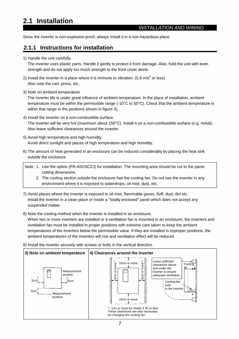
3) Note on ambient temperatureThe inverter life is under great influence of ambient temperature. In the place of installation, ambienttemperature must be within the permissible range (-10°C to 50°C). Check that the ambient temperature iswithin that range in the positions shown in figure 3).
4) Install the inverter on a non-combustible surface.The inverter will be very hot (maximum about 150°C). Install it on a non-combustible surface (e.g. metal).Also leave sufficient clearances around the inverter.
5) Avoid high temperature and high humidity.Avoid direct sunlight and places of high temperature and high humidity.
6) The amount of heat generated in an enclosure can be reduced considerably by placing the heat sinkoutside the enclosure.
Note: 1. Use the option (FR-A5CN ) for installation. The mounting area should be cut to the panelcutting dimensions.
2. The cooling section outside the enclosure has the cooling fan. Do not use the inverter in anyenvironment where it is exposed to waterdrops, oil mist, dust, etc.
7) Avoid places where the inverter is exposed to oil mist, flammable gases, fluff, dust, dirt etc.Install the inverter in a clean place or inside a "totally enclosed" panel which does not accept anysuspended matter.
8) Note the cooling method when the inverter is installed in an enclosure.When two or more inverters are installed or a ventilation fan is mounted in an enclosure, the inverters andventilation fan must be installed in proper positions with extreme care taken to keep the ambienttemperatures of the inverters below the permissible value. If they are installed in improper positions, theambient temperatures of the inverters will rise and ventilation effect will be reduced.
9) Install the inverter securely with screws or bolts in the vertical direction.
3) Note on ambient temperature
Measurementposition
Measurementposition
5cm5cm
5cm
4) Clearances around the inverter
10cm or more
5cm
or m
ore
* Leave sufficientclearances above and under the inverter to ensureadequate ventilation.
Cooling fanbuiltin the inverter
Coolingair
5cm
or m
ore
*
10cm or more
*: 1cm or more for model 3.7K or lessThese clearances are also necessaryfor changing the cooling fan.
INSTALLATION AND WIRING
8
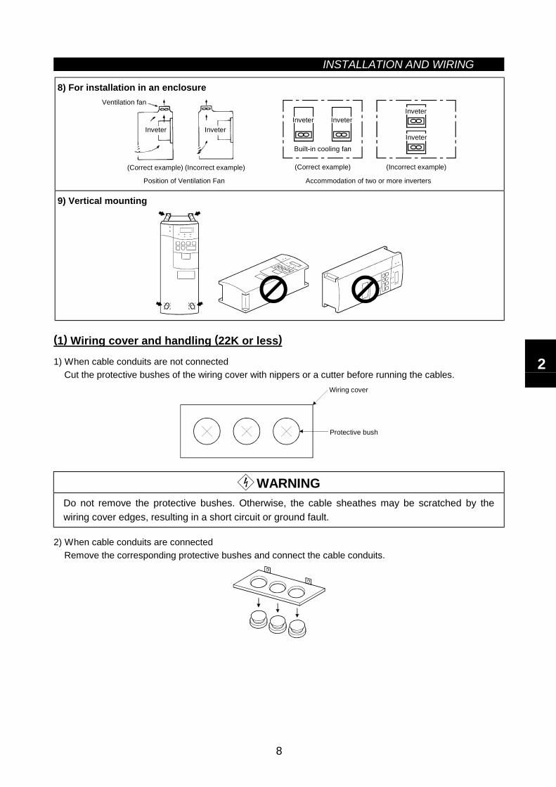
8) For installation in an enclosureVentilation fan
(Correct example)
Position of Ventilation Fan
Inveter InveterInveter
(Correct example) (Incorrect example)
Built-in cooling fan
InveterInveter
Inveter
Accommodation of two or more inverters
(Incorrect example)
9) Vertical mounting
(1) Wiring cover and handling (22K or less)
1) When cable conduits are not connectedCut the protective bushes of the wiring cover with nippers or a cutter before running the cables.
Wiring cover
Protective bush
WARNINGDo not remove the protective bushes. Otherwise, the cable sheathes may be scratched by thewiring cover edges, resulting in a short circuit or ground fault.
2) When cable conduits are connectedRemove the corresponding protective bushes and connect the cable conduits.
2
2.2 WiringINSTALLATION AND WIRING
9
2.2 Wiring
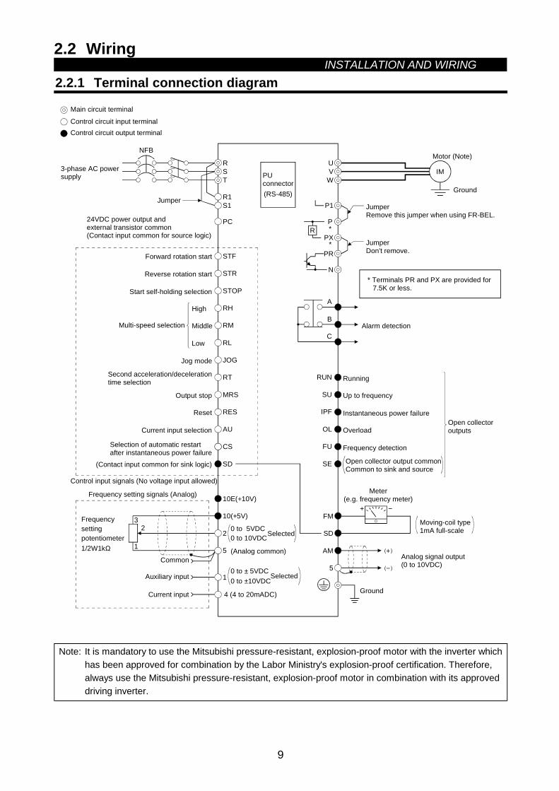
2.2.1 Terminal connection diagram
NFB
RST
R1S1
PC
STF
STR
STOP
RH
RM
RL
JOG
RT
MRS
RES
AU
CS
SD
10E(+10V)
10(+5V)
2
5
23
1
1
4 (4 to 20mADC)
Frequencysettingpotentiometer1/2W1kΩ
RUN
SU
IPF
OL
FU
SE
FM
SD
IM
A
B
C
UV
W
P1
P
PX
PR
N
+ −
(−)
(+)AM
5
R
Ground
Main circuit terminal
Control circuit input terminalControl circuit output terminal
3-phase AC powersupply
Jumper
24VDC power output andexternal transistor common(Contact input common for source logic)
Forward rotation start
Reverse rotation start
Start self-holding selection
High
Middle
Low
Jog mode
Second acceleration/decelerationtime selection
Output stop
Reset
Current input selection
Selection of automatic restart after instantaneous power failure
(Contact input common for sink logic)
Control input signals (No voltage input allowed)
Frequency setting signals (Analog)
Common
Auxiliary input
Current input
0 to 5VDC0 to 10VDCSelected
(Analog common)
0 to ± 5VDC0 to ±10VDC
Selected
*
*
Motor (Note)
Ground
JumperRemove this jumper when using FR-BEL.
JumperDon't remove.
Alarm detection
Running
Up to frequency
Instantaneous power failure
Overload
Frequency detection
Open collector output commonCommon to sink and source
Open collector outputs
Meter(e.g. frequency meter)
Moving-coil type1mA full-scale
Analog signal output(0 to 10VDC)
Multi-speed selection
PUconnector(RS-485)
* Terminals PR and PX are provided for 7.5K or less.
Note: It is mandatory to use the Mitsubishi pressure-resistant, explosion-proof motor with the inverter whichhas been approved for combination by the Labor Ministry's explosion-proof certification. Therefore,always use the Mitsubishi pressure-resistant, explosion-proof motor in combination with its approveddriving inverter.
INSTALLATION AND WIRING
10
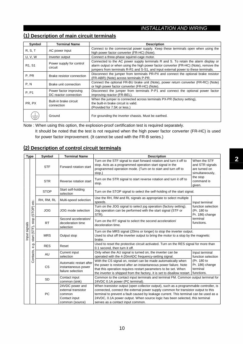
(1) Description of main circuit terminalsSymbol Terminal Name Description
R, S, T AC power input Connect to the commercial power supply. Keep these terminals open when using thehigh power factor converter (FR-HC) (Note).
U, V, W Inverter output Connect a three-phase squirrel-cage motor.
R1, S1 Power supply for controlcircuit
Connected to the AC power supply terminals R and S. To retain the alarm display oralarm output or when using the high power factor converter (FR-HC) (Note), remove thejumpers from terminals R-R1 and S-S1, and input external power to these terminals.
P, PR Brake resistor connection Disconnect the jumper from terminals PR-PX and connect the optional brake resistor(FR-ABR) (Note) across terminals P-PR.
P, N Brake unit connection Connect the optional FR-BU brake unit (Note), power return converter (FR-RC) (Note)or high power factor converter (FR-HC) (Note).
P, P1 Power factor improvingDC reactor connection
Disconnect the jumper from terminals P-P1 and connect the optional power factorimproving reactor (FR-BEL).
PR, PX Built-in brake circuitconnection
When the jumper is connected across terminals PX-PR (factory setting),the built-in brake circuit is valid.(Provided for 7.5K or less.)
Ground For grounding the inverter chassis. Must be earthed.
Note : When using this option, the explosion-proof certification test is required separately.It should be noted that the test is not required when the high power factor converter (FR-HC) is usedfor power factor improvement. (It cannot be used with the FR-B series.)
(2) Description of control circuit terminalsType Symbol Terminal Name Description
STF Forward rotation start
Turn on the STF signal to start forward rotation and turn it off tostop. Acts as a programmed operation start signal in theprogrammed operation mode. (Turn on to start and turn off tostop.)
STR Reverse rotation start Turn on the STR signal to start reverse rotation and turn it off tostop.
When the STFand STR signalsare turned onsimultaneously,the stopcommand isgiven.
STOP Start self-holdingselection Turn on the STOP signal to select the self-holding of the start signal.
RH, RM, RL Multi-speed selection Use the RH, RM and RL signals as appropriate to select multiplespeeds.
JOG JOG mode selectionTurn on the JOG signal to select jog operation (factory setting).Jog operation can be performed with the start signal (STF orSTR).
RTSecond acceleration/deceleration timeselection
Turn on the RT signal to select the second acceleration/deceleration time.
Input terminalfunction selection(Pr. 180 toPr. 186) changeterminalfunctions.
MRS Output stopTurn on the MRS signal (20ms or longer) to stop the inverter output.Used to shut off the inverter output to bring the motor to a stop by the magneticbrake.
RES Reset Used to reset the protective circuit activated. Turn on the RES signal for more than0.1 second, then turn it off.
AU Current inputselection
Only when the AU signal is turned on, the inverter can beoperated with the 4-20mADC frequency-setting signal.
CSAutomatic restart afterinstantaneous powerfailure selection
With the CS signal on, restart can be made automatically whenthe power is restored after an instantaneous power failure. Notethat this operation requires restart parameters to be set. Whenthe inverter is shipped from the factory, it is set to disallow restart.
Input terminalfunction selection(Pr. 180 toPr. 186) changeterminalfunctions.
SD Contact inputcommon (sink)
Common to the contact input terminals and terminal FM. Common output terminal for24VDC 0.1A power (PC terminal).
Inpu
t sig
nals
Con
tact
s, e
.g. s
tart
(STF
), st
op (S
TOP)
etc
.
PC
24VDC power andexternal transistorcommonContact inputcommon (source)
When transistor output (open collector output), such as a programmable controller, isconnected, connect the external power supply common for transistor output to thisterminal to prevent a fault caused by leakage current. This terminal can be used as a24VDC, 0.1A power output. When source logic has been selected, this terminalserves as a contact input common.
2
INSTALLATION AND WIRING
11
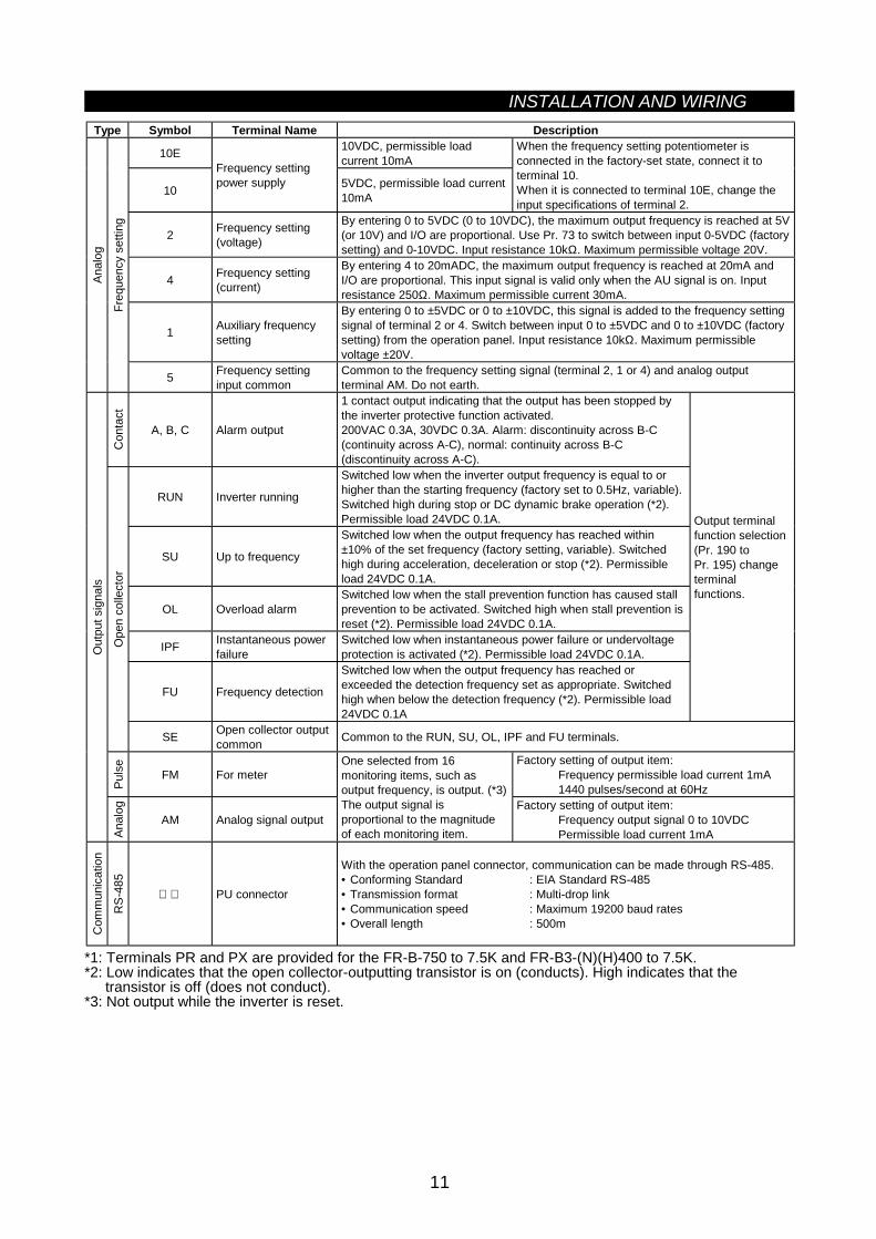
Type Symbol Terminal Name Description
10E 10VDC, permissible loadcurrent 10mA
10
Frequency settingpower supply 5VDC, permissible load current
10mA
When the frequency setting potentiometer isconnected in the factory-set state, connect it toterminal 10.When it is connected to terminal 10E, change theinput specifications of terminal 2.
2 Frequency setting(voltage)
By entering 0 to 5VDC (0 to 10VDC), the maximum output frequency is reached at 5V(or 10V) and I/O are proportional. Use Pr. 73 to switch between input 0-5VDC (factorysetting) and 0-10VDC. Input resistance 10kΩ. Maximum permissible voltage 20V.
4 Frequency setting(current)
By entering 4 to 20mADC, the maximum output frequency is reached at 20mA andI/O are proportional. This input signal is valid only when the AU signal is on. Inputresistance 250Ω. Maximum permissible current 30mA.
1 Auxiliary frequencysetting
By entering 0 to ±5VDC or 0 to ±10VDC, this signal is added to the frequency settingsignal of terminal 2 or 4. Switch between input 0 to ±5VDC and 0 to ±10VDC (factorysetting) from the operation panel. Input resistance 10kΩ. Maximum permissiblevoltage ±20V.
Anal
og
Freq
uenc
y se
tting
5 Frequency settinginput common
Common to the frequency setting signal (terminal 2, 1 or 4) and analog outputterminal AM. Do not earth.
Con
tact
A, B, C Alarm output
1 contact output indicating that the output has been stopped bythe inverter protective function activated.200VAC 0.3A, 30VDC 0.3A. Alarm: discontinuity across B-C(continuity across A-C), normal: continuity across B-C(discontinuity across A-C).
RUN Inverter running
Switched low when the inverter output frequency is equal to orhigher than the starting frequency (factory set to 0.5Hz, variable).Switched high during stop or DC dynamic brake operation (*2).Permissible load 24VDC 0.1A.
SU Up to frequency
Switched low when the output frequency has reached within±10% of the set frequency (factory setting, variable). Switchedhigh during acceleration, deceleration or stop (*2). Permissibleload 24VDC 0.1A.
OL Overload alarmSwitched low when the stall prevention function has caused stallprevention to be activated. Switched high when stall prevention isreset (*2). Permissible load 24VDC 0.1A.
IPF Instantaneous powerfailure
Switched low when instantaneous power failure or undervoltageprotection is activated (*2). Permissible load 24VDC 0.1A.
FU Frequency detection
Switched low when the output frequency has reached orexceeded the detection frequency set as appropriate. Switchedhigh when below the detection frequency (*2). Permissible load24VDC 0.1A
Output terminalfunction selection(Pr. 190 toPr. 195) changeterminalfunctions.
Ope
n co
llect
or
SE Open collector outputcommon Common to the RUN, SU, OL, IPF and FU terminals.
Puls
e
FM For meterFactory setting of output item:
Frequency permissible load current 1mA1440 pulses/second at 60Hz
Out
put s
igna
ls
Anal
og
AM Analog signal output
One selected from 16monitoring items, such asoutput frequency, is output. (*3)The output signal isproportional to the magnitudeof each monitoring item.
Factory setting of output item:Frequency output signal 0 to 10VDCPermissible load current 1mA
Com
mun
icat
ion
RS-
485
PU connector
With the operation panel connector, communication can be made through RS-485.• Conforming Standard : EIA Standard RS-485• Transmission format : Multi-drop link• Communication speed : Maximum 19200 baud rates• Overall length : 500m
*1: Terminals PR and PX are provided for the FR-B-750 to 7.5K and FR-B3-(N)(H)400 to 7.5K.*2: Low indicates that the open collector-outputting transistor is on (conducts). High indicates that the
transistor is off (does not conduct).*3: Not output while the inverter is reset.
INSTALLATION AND WIRING
12
2.2.2 Wiring of the main circuit(1) Wiring instructions
1) Crimping terminals with insulation sleeves are recommended for use with the power and motor cables.2) Cut the protective bushes of the wiring cover when running the cables. (22K or less)3) Power must not be applied to the output terminals (U, V, W) of the inverter. Otherwise the inverter will be
damaged.4) After wiring, wire off-cuts must not be left in the inverter.
Wire off-cuts can cause an alarm, failure or malfunction. Always keep the inverter clean.When drilling mounting holes in a control box etc., exercise care to prevent chips and other foreign matterfrom entering the inverter.
5) Use cables of the recommended size for wiring to make the voltage drop 2% or less.If the wiring distance is long between the inverter and motor, a main circuit cable voltage drop will causethe motor torque to decrease especially at the output of a low frequency. (The selection example at thewiring length of 20m is given on page 16.)
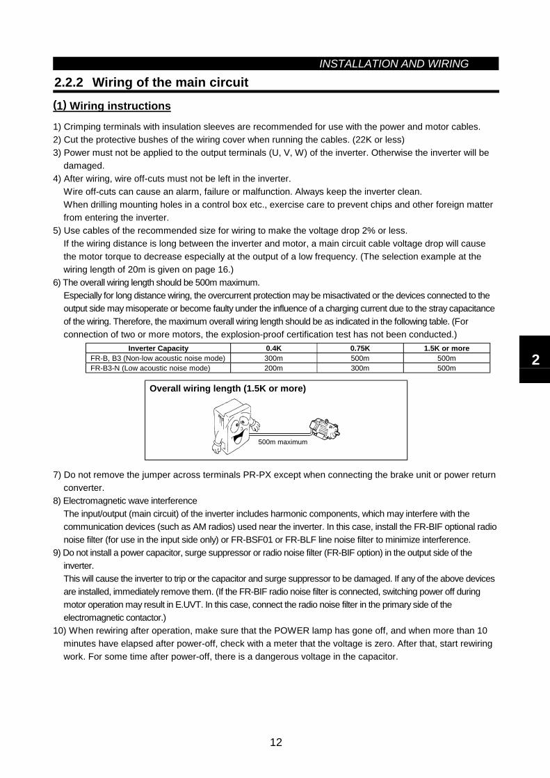
6) The overall wiring length should be 500m maximum.Especially for long distance wiring, the overcurrent protection may be misactivated or the devices connected to theoutput side may misoperate or become faulty under the influence of a charging current due to the stray capacitanceof the wiring. Therefore, the maximum overall wiring length should be as indicated in the following table. (Forconnection of two or more motors, the explosion-proof certification test has not been conducted.)
Inverter Capacity 0.4K 0.75K 1.5K or moreFR-B, B3 (Non-low acoustic noise mode) 300m 500m 500mFR-B3-N (Low acoustic noise mode) 200m 300m 500m
Overall wiring length (1.5K or more)
500m maximum
7) Do not remove the jumper across terminals PR-PX except when connecting the brake unit or power returnconverter.
8) Electromagnetic wave interferenceThe input/output (main circuit) of the inverter includes harmonic components, which may interfere with thecommunication devices (such as AM radios) used near the inverter. In this case, install the FR-BIF optional radionoise filter (for use in the input side only) or FR-BSF01 or FR-BLF line noise filter to minimize interference.
9) Do not install a power capacitor, surge suppressor or radio noise filter (FR-BIF option) in the output side of theinverter.This will cause the inverter to trip or the capacitor and surge suppressor to be damaged. If any of the above devicesare installed, immediately remove them. (If the FR-BIF radio noise filter is connected, switching power off duringmotor operation may result in E.UVT. In this case, connect the radio noise filter in the primary side of theelectromagnetic contactor.)
10) When rewiring after operation, make sure that the POWER lamp has gone off, and when more than 10minutes have elapsed after power-off, check with a meter that the voltage is zero. After that, start rewiringwork. For some time after power-off, there is a dangerous voltage in the capacitor.
2
INSTALLATION AND WIRING
13
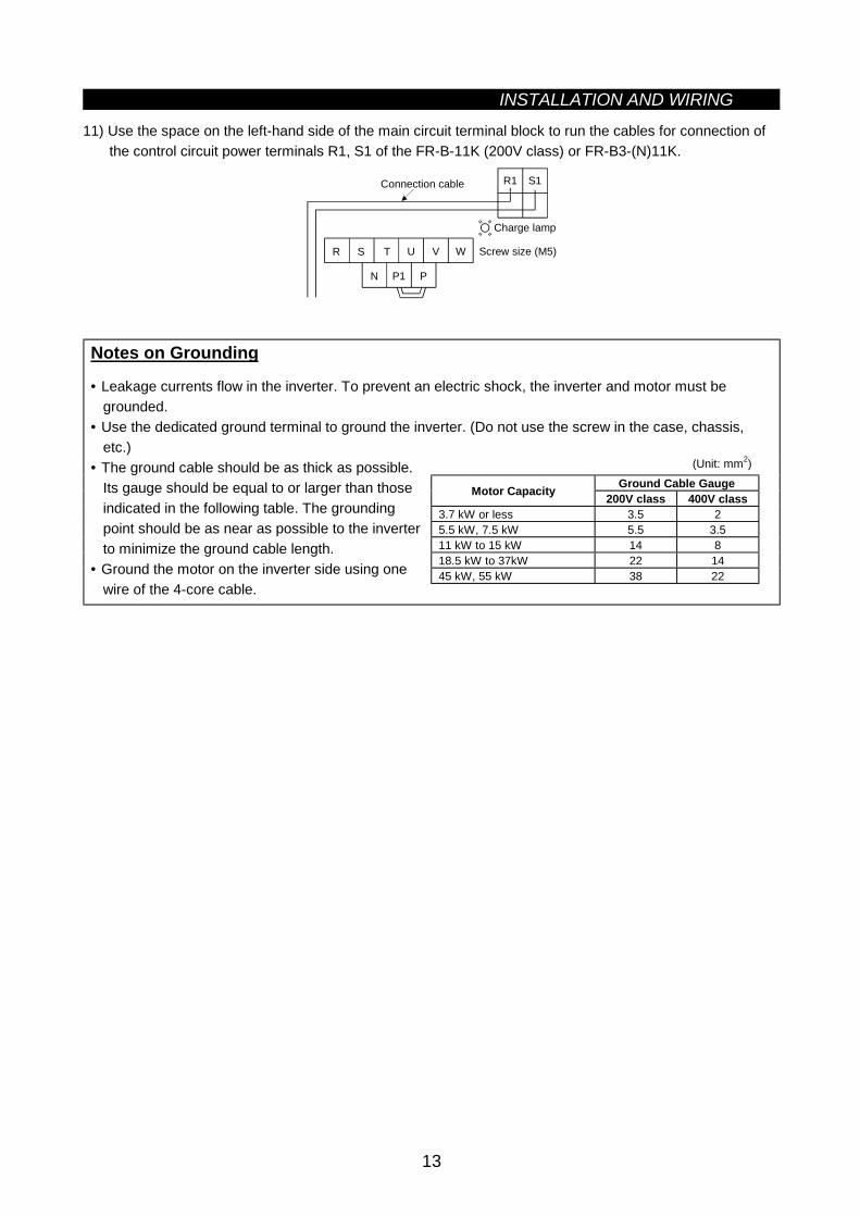
11) Use the space on the left-hand side of the main circuit terminal block to run the cables for connection ofthe control circuit power terminals R1, S1 of the FR-B-11K (200V class) or FR-B3-(N)11K.
N
U V W
P1
R1 S1
P
Screw size (M5)
Connection cable
Charge lamp
TR S
Notes on Grounding
• Leakage currents flow in the inverter. To prevent an electric shock, the inverter and motor must begrounded.
• Use the dedicated ground terminal to ground the inverter. (Do not use the screw in the case, chassis,etc.)
(Unit: mm2)Ground Cable GaugeMotor Capacity 200V class 400V class
3.7 kW or less 3.5 25.5 kW, 7.5 kW 5.5 3.511 kW to 15 kW 14 818.5 kW to 37kW 22 1445 kW, 55 kW 38 22
• The ground cable should be as thick as possible.Its gauge should be equal to or larger than thoseindicated in the following table. The groundingpoint should be as near as possible to the inverterto minimize the ground cable length.
• Ground the motor on the inverter side using onewire of the 4-core cable.
INSTALLATION AND WIRING
14
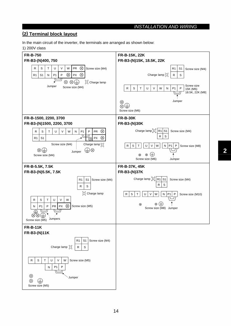
(2) Terminal block layout
In the main circuit of the inverter, the terminals are arranged as shown below:1) 200V class
FR-B-750FR-B3-(N)400, 750
R S T U V W PR
R1 S1 N P1 P PX
Jumper
Screw size (M4)
Charge lampScrew size (M4)
FR-B-15K, 22KFR-B3-(N)15K, 18.5K, 22K
R S T U V W N P1 P
R S
R1 S1
Screw size15K (M6)18.5K, 22K (M8)
Jumper
Charge lamp
Screw size (M4)
Screw size (M6)
FR-B-1500, 2200, 3700FR-B3-(N)1500, 2200, 3700
R
R1
S T U V W PR
S1
N P1 P
PX
Jumper
Screw size (M4) Charge lamp
Screw size (M4)
FR-B-30KFR-B3-(N)30K
R S T U V W
R1 S1
N P1 P
R S
Charge lamp Screw size (M4)
Screw size (M8)
Screw size (M6) Jumper
FR-B-5.5K, 7.5KFR-B3-(N)5.5K, 7.5K
R S T U V W
N P1 P PR PX
R1
R
S1
S
Charge lamp
Screw size (M5)
Screw size (M4)
JumpersScrew size (M5)
FR-B-37K, 45KFR-B3-(N)37K
R S T U V W
R1 S1
N P1 P
R S
Charge lamp Screw size (M4)
Screw size (M10)
Screw size (M8) Jumper
FR-B-11KFR-B3-(N)11K
R
N
S T U V W
P1 P
R1
R
S1
SCharge lamp
Screw size (M4)
Jumper
Screw size (M5)
Screw size (M5)
2
INSTALLATION AND WIRING
15
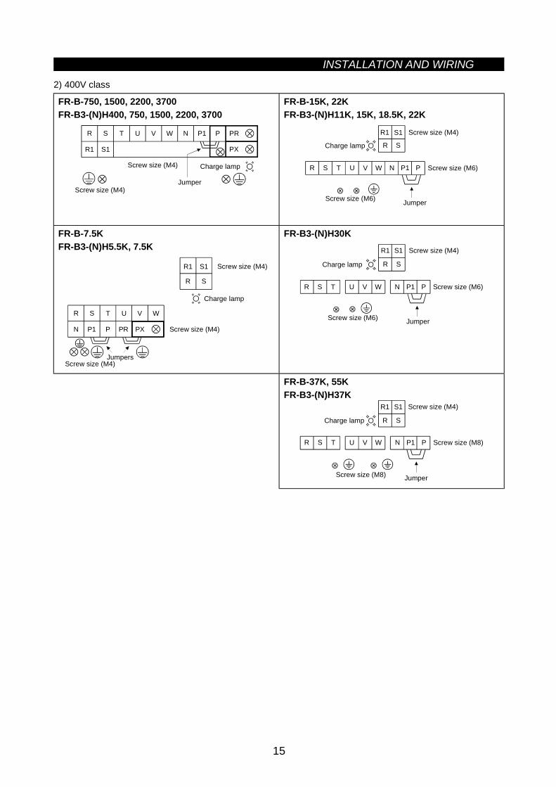
2) 400V class
FR-B-750, 1500, 2200, 3700FR-B3-(N)H400, 750, 1500, 2200, 3700
Jumper
Charge lamp
Screw size (M4)
R T U V W N P1 P PR
R1
S
S1 PX
Screw size (M4)
FR-B-15K, 22KFR-B3-(N)H11K, 15K, 18.5K, 22K
Jumper
Charge lamp
Screw size (M4)R1
R T U V W N P1 PS
S1
Screw size (M6)
Screw size (M6)
R S
FR-B-7.5KFR-B3-(N)H5.5K, 7.5K
Jumpers
Charge lamp
Screw size (M4)
R1
R T U V WS
S1
N P1 P PR PX Screw size (M4)
Screw size (M4)
R S
FR-B3-(N)H30K
R T U V W N P1 PS
Jumper
Charge lamp
R1 S1
Screw size (M6)
R S
Screw size (M4)
Screw size (M6)
FR-B-37K, 55KFR-B3-(N)H37K
R1 S1
R S
R T U V W N P1 PS
Jumper
Charge lamp
Screw size (M8)
Screw size (M4)
Screw size (M8)
INSTALLATION AND WIRING
16
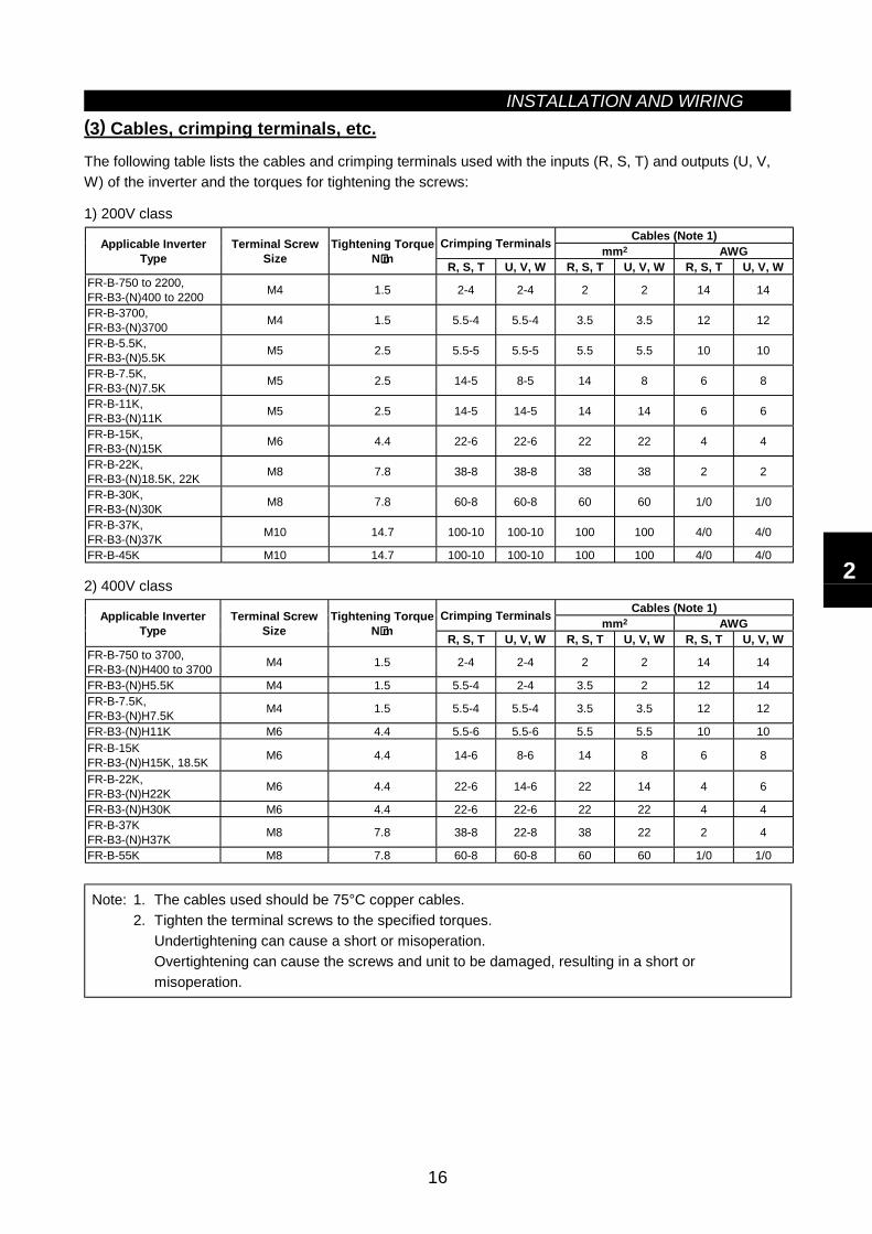
(3) Cables, crimping terminals, etc.
The following table lists the cables and crimping terminals used with the inputs (R, S, T) and outputs (U, V,W) of the inverter and the torques for tightening the screws:
1) 200V classCables (Note 1)Crimping Terminals mm2 AWGApplicable Inverter
TypeTerminal Screw
SizeTightening Torque
N⋅⋅⋅⋅m R, S, T U, V, W R, S, T U, V, W R, S, T U, V, WFR-B-750 to 2200,FR-B3-(N)400 to 2200 M4 1.5 2-4 2-4 2 2 14 14
FR-B-3700,FR-B3-(N)3700 M4 1.5 5.5-4 5.5-4 3.5 3.5 12 12
FR-B-5.5K,FR-B3-(N)5.5K M5 2.5 5.5-5 5.5-5 5.5 5.5 10 10
FR-B-7.5K,FR-B3-(N)7.5K M5 2.5 14-5 8-5 14 8 6 8
FR-B-11K,FR-B3-(N)11K M5 2.5 14-5 14-5 14 14 6 6
FR-B-15K,FR-B3-(N)15K M6 4.4 22-6 22-6 22 22 4 4
FR-B-22K,FR-B3-(N)18.5K, 22K M8 7.8 38-8 38-8 38 38 2 2
FR-B-30K,FR-B3-(N)30K M8 7.8 60-8 60-8 60 60 1/0 1/0
FR-B-37K,FR-B3-(N)37K M10 14.7 100-10 100-10 100 100 4/0 4/0
FR-B-45K M10 14.7 100-10 100-10 100 100 4/0 4/0
2) 400V classCables (Note 1)Crimping Terminals mm2 AWGApplicable Inverter
TypeTerminal Screw
SizeTightening Torque
N⋅⋅⋅⋅m R, S, T U, V, W R, S, T U, V, W R, S, T U, V, WFR-B-750 to 3700,FR-B3-(N)H400 to 3700 M4 1.5 2-4 2-4 2 2 14 14
FR-B3-(N)H5.5K M4 1.5 5.5-4 2-4 3.5 2 12 14FR-B-7.5K,FR-B3-(N)H7.5K M4 1.5 5.5-4 5.5-4 3.5 3.5 12 12
FR-B3-(N)H11K M6 4.4 5.5-6 5.5-6 5.5 5.5 10 10FR-B-15KFR-B3-(N)H15K, 18.5K M6 4.4 14-6 8-6 14 8 6 8
FR-B-22K,FR-B3-(N)H22K M6 4.4 22-6 14-6 22 14 4 6
FR-B3-(N)H30K M6 4.4 22-6 22-6 22 22 4 4FR-B-37KFR-B3-(N)H37K M8 7.8 38-8 22-8 38 22 2 4
FR-B-55K M8 7.8 60-8 60-8 60 60 1/0 1/0
Note: 1. The cables used should be 75°C copper cables.2. Tighten the terminal screws to the specified torques.
Undertightening can cause a short or misoperation.Overtightening can cause the screws and unit to be damaged, resulting in a short ormisoperation.
2
INSTALLATION AND WIRING
17
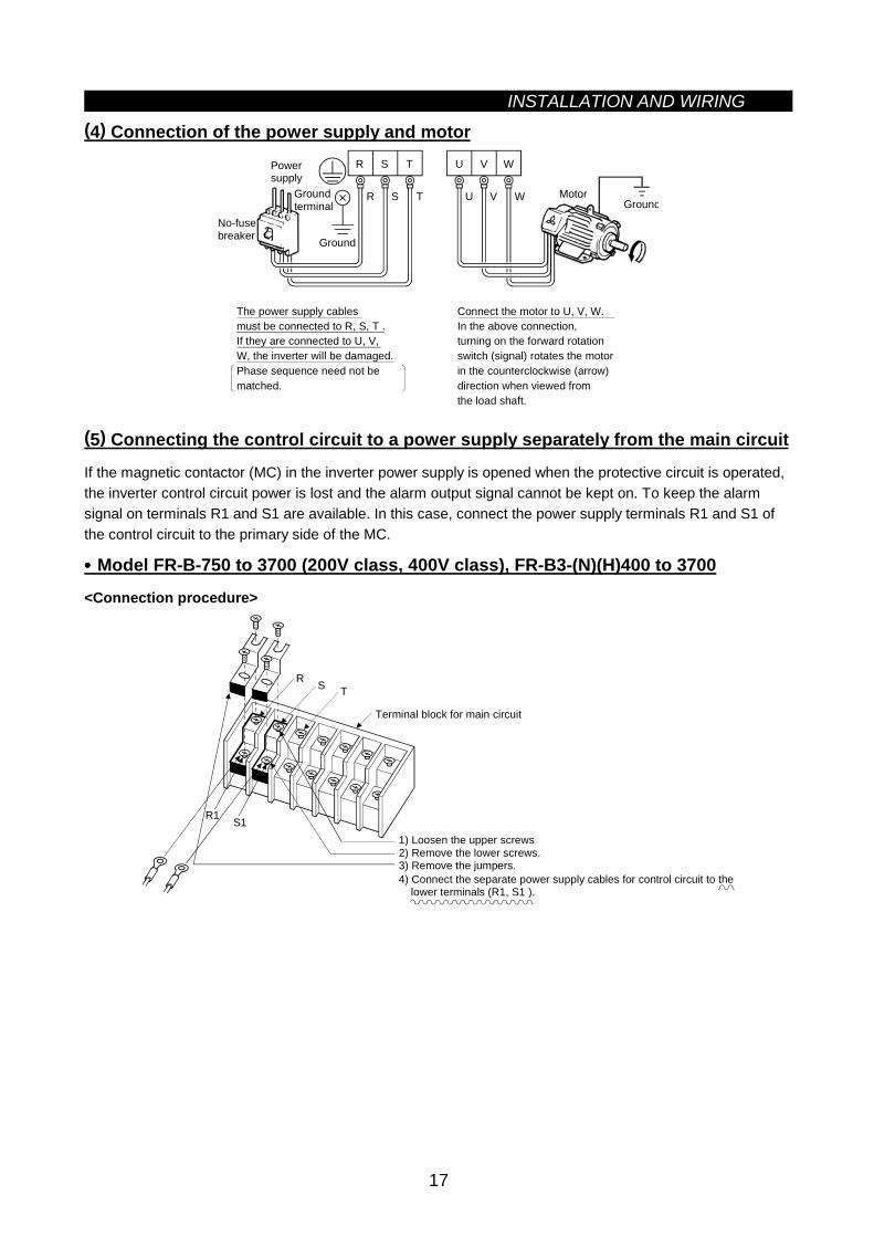
(4) Connection of the power supply and motor
Ground
Ground
Groundterminal
Powersupply
U V W
U V W Motor
No-fusebreaker
The power supply cablesmust be connected to R, S, T .If they are connected to U, V, W, the inverter will be damaged.Phase sequence need not be matched.
Connect the motor to U, V, W.In the above connection,turning on the forward rotationswitch (signal) rotates the motorin the counterclockwise (arrow)direction when viewed fromthe load shaft.
R S T
R S T
(5) Connecting the control circuit to a power supply separately from the main circuit
If the magnetic contactor (MC) in the inverter power supply is opened when the protective circuit is operated,the inverter control circuit power is lost and the alarm output signal cannot be kept on. To keep the alarmsignal on terminals R1 and S1 are available. In this case, connect the power supply terminals R1 and S1 ofthe control circuit to the primary side of the MC.
•••• Model FR-B-750 to 3700 (200V class, 400V class), FR-B3-(N)(H)400 to 3700
<Connection procedure>
R S T
R1 S1
4) Connect the separate power supply cables for control circuit to the lower terminals (R1, S1 ).
Terminal block for main circuit
1) Loosen the upper screws2) Remove the lower screws.3) Remove the jumpers.
INSTALLATION AND WIRING
18
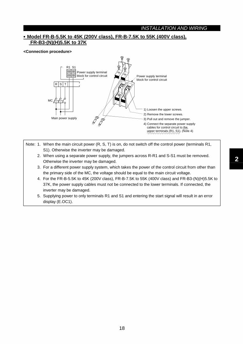
•••• Model FR-B-5.5K to 45K (200V class), FR-B-7.5K to 55K (400V class), FR-B3-(N)(H)5.5K to 37K
<Connection procedure>
MC
1) Loosen the upper screws.2) Remove the lower screws.3) Pull out and remove the jumper.4) Connect the separate power supply cables for control circuit to the upper terminals (R1, S1). (Note 4)
Power supply terminal block for control circuit
Main power supply
Power supply terminalblock for control circuit
R S T
R1 S1
Note: 1. When the main circuit power (R, S, T) is on, do not switch off the control power (terminals R1,S1). Otherwise the inverter may be damaged.
2. When using a separate power supply, the jumpers across R-R1 and S-S1 must be removed.Otherwise the inverter may be damaged.
3. For a different power supply system, which takes the power of the control circuit from other thanthe primary side of the MC, the voltage should be equal to the main circuit voltage.
4. For the FR-B-5.5K to 45K (200V class), FR-B-7.5K to 55K (400V class) and FR-B3-(N)(H)5.5K to37K, the power supply cables must not be connected to the lower terminals. If connected, theinverter may be damaged.
5. Supplying power to only terminals R1 and S1 and entering the start signal will result in an errordisplay (E.OC1).
2
INSTALLATION AND WIRING
19
2.2.3 Wiring of the control circuit(1) Wiring instructions
1) Terminals SD, SE and 5 are common to the I/O signals and isolated from each other. These commonterminals must not be connected to each other or earthed.
2) Use shielded or twisted cables for connection to the control circuit terminals and run them away from themain and powers circuits (including the 200V relay sequence circuit).
3) The frequency-input signals to the control circuit are micro currents. When contacts are required, use twoor more parallel micro signal contacts or a twin contact to prevent a contact fault.
4) It is recommended to use the cables of 0.75mm2 gauge for connection to the control circuit terminals.If the cable gauge used is 1.25mm2 or more, the front cover may be lifted when there are many cablesrunning or the cables are run improperly, resulting in an operation panel or parameter unit contact fault.
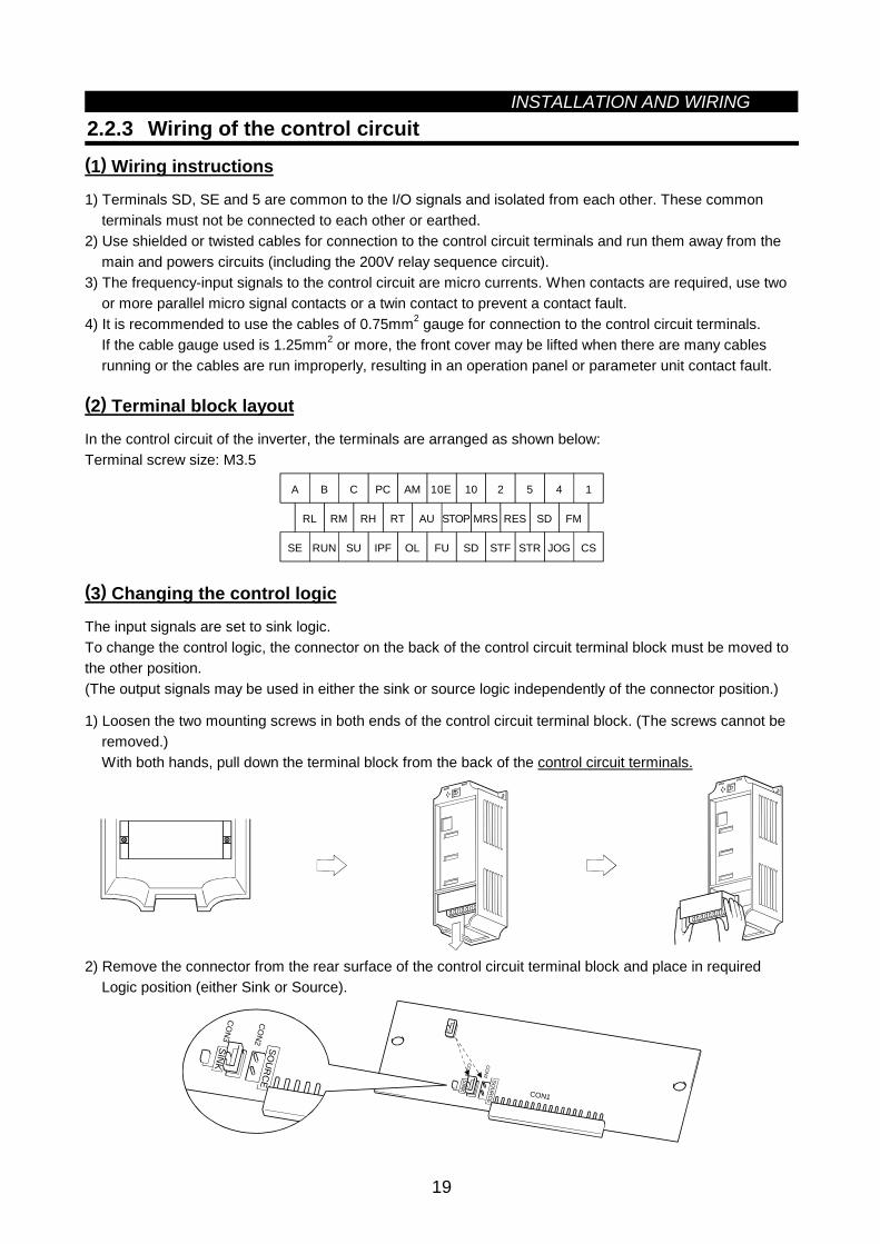
(2) Terminal block layout
In the control circuit of the inverter, the terminals are arranged as shown below:Terminal screw size: M3.5
A
RL
SE RUN SU IPF OL FU SD STF STR JOG CS
RM RH RT AU STOP MRS RES SD FM
B C PC AM 10E 10 2 5 4 1
(3) Changing the control logic
The input signals are set to sink logic.To change the control logic, the connector on the back of the control circuit terminal block must be moved tothe other position.(The output signals may be used in either the sink or source logic independently of the connector position.)
1) Loosen the two mounting screws in both ends of the control circuit terminal block. (The screws cannot beremoved.)With both hands, pull down the terminal block from the back of the control circuit terminals.
2) Remove the connector from the rear surface of the control circuit terminal block and place in requiredLogic position (either Sink or Source).
CON1
SINK
CO
N3
CO
N2
SOU
RC
E
SINK
CO
N3
CO
N2
SOU
RC
E
INSTALLATION AND WIRING
20
3) Using cares not to bend the pins of the control circuit connector, reinstall the control circuit terminal blockand fix it with the mounting screws.
Note: 1. Make sure that the control circuit connector is fitted correctly.2. While power is on, never disconnect the control circuit terminal block.3. The sink-source logic changeover connector must be fitted in only one of those positions. If it is
fitted in both positions at the same time, the inverter may be damaged.
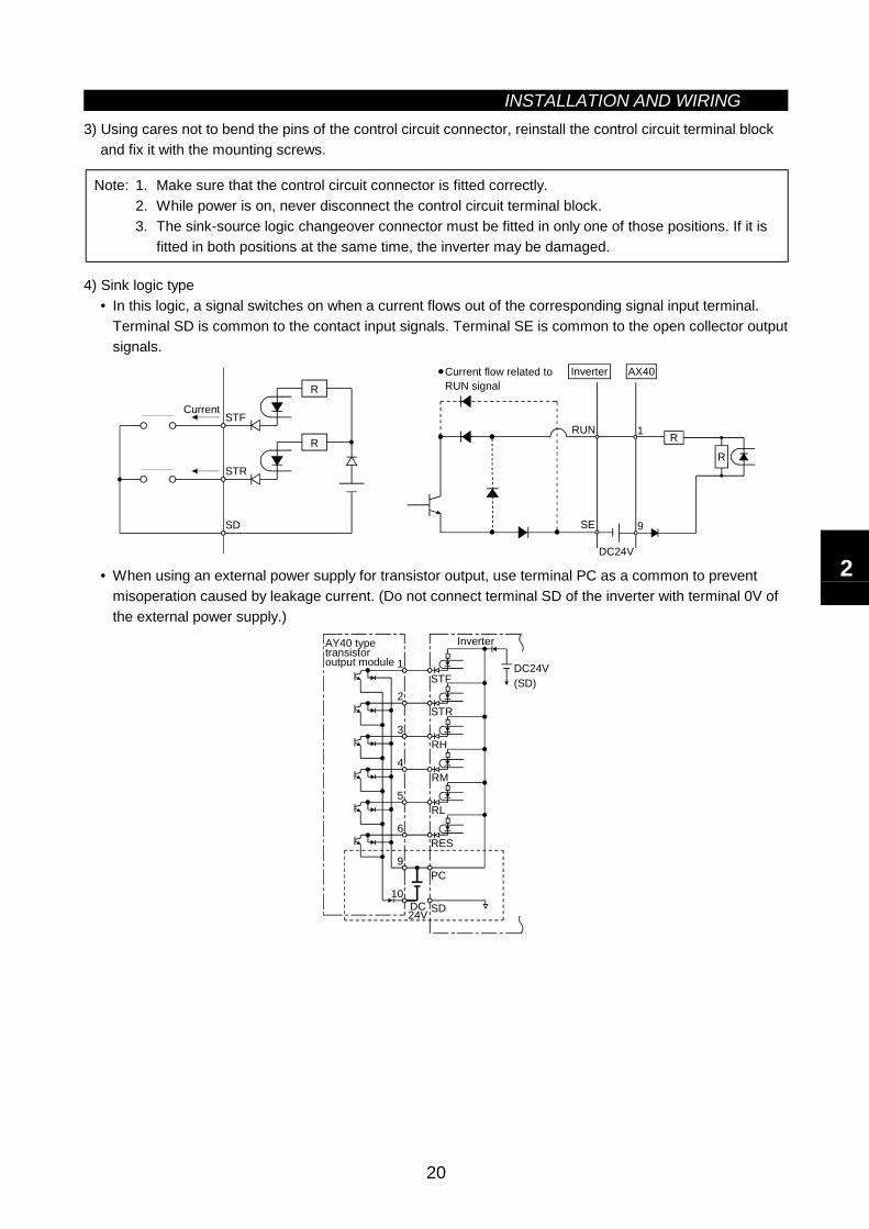
4) Sink logic type• In this logic, a signal switches on when a current flows out of the corresponding signal input terminal.
Terminal SD is common to the contact input signals. Terminal SE is common to the open collector outputsignals.
R
R
STF
STR
SD
Current
RUN
SE
1
9
R
R
DC24V
AX40Current flow related to RUN signal
Inverter
• When using an external power supply for transistor output, use terminal PC as a common to preventmisoperation caused by leakage current. (Do not connect terminal SD of the inverter with terminal 0V ofthe external power supply.)
1
2
3
4
5
6
9
10DC24V SD
PC
RES
RL
RM
RH
STR
STFDC24V(SD)
AY40 type transistoroutput module
Inverter
2
INSTALLATION AND WIRING
21
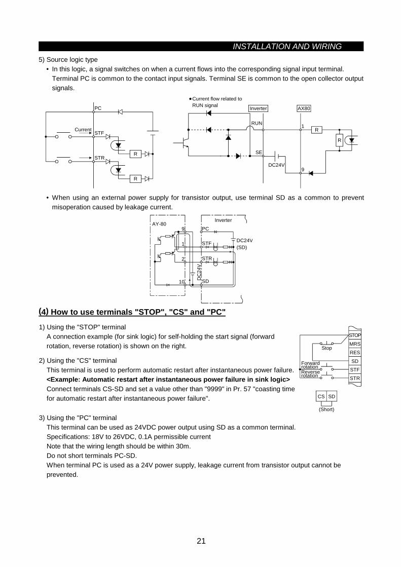
5) Source logic type• In this logic, a signal switches on when a current flows into the corresponding signal input terminal.
Terminal PC is common to the contact input signals. Terminal SE is common to the open collector outputsignals.
PC
STF
STRR
R
Current
DC24V
RUN
SE
1
9
R
R
Current flow related to RUN signal AX80Inverter
• When using an external power supply for transistor output, use terminal SD as a common to preventmisoperation caused by leakage current.
AY-809
1
2
10
PC
STF
STR
SD
DC24V(SD)
DC
24V
Inverter
(4) How to use terminals "STOP", "CS" and "PC"
1) Using the "STOP" terminalA connection example (for sink logic) for self-holding the start signal (forwardrotation, reverse rotation) is shown on the right.
2) Using the "CS" terminalThis terminal is used to perform automatic restart after instantaneous power failure.<Example: Automatic restart after instantaneous power failure in sink logic>Connect terminals CS-SD and set a value other than "9999" in Pr. 57 "coasting timefor automatic restart after instantaneous power failure".
MRS
RES
SDSTF
STR
STOP
Reverserotation
Stop
Forwardrotation
CS SD
(Short)
3) Using the "PC" terminalThis terminal can be used as 24VDC power output using SD as a common terminal.Specifications: 18V to 26VDC, 0.1A permissible currentNote that the wiring length should be within 30m.Do not short terminals PC-SD.When terminal PC is used as a 24V power supply, leakage current from transistor output cannot beprevented.
INSTALLATION AND WIRING
22
2.2.4 Connection to the PU connector(1) When connecting the operation panel or parameter unit using a connection cable
<Recommended cable connector>• Parameter unit connection cable (FR-CB2) (option) or the following connector and cable.• Connector: RJ45 connector
Example: 5-554720-3, Nippon AMP• Cable: Cable conforming to EIA568 (e.g. 10BASE-T cable)
Example: SGLPEV 0.5mm×4P, MITSUBISHI CABLE INDUSTRIES, LTD.
Note: The maximum wiring length is 20m.
(2) For RS-485 communication
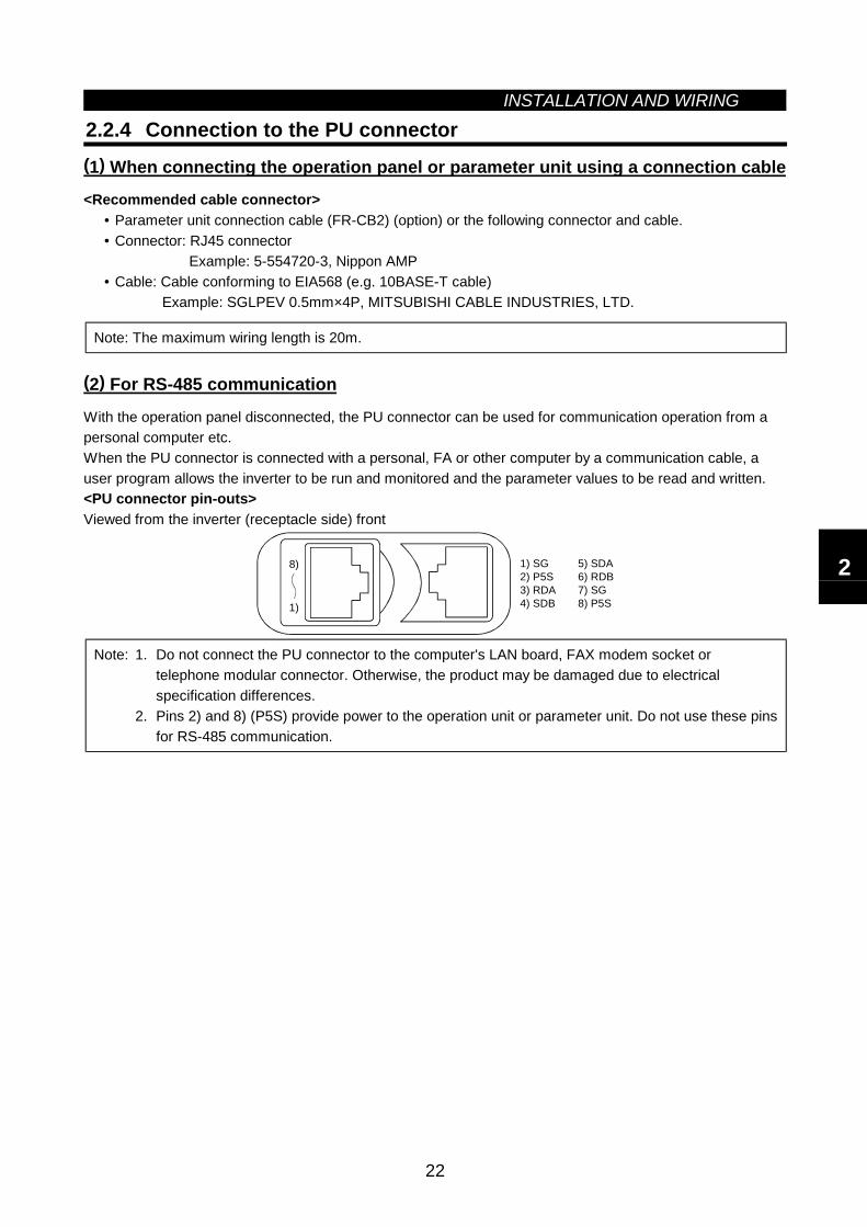
With the operation panel disconnected, the PU connector can be used for communication operation from apersonal computer etc.When the PU connector is connected with a personal, FA or other computer by a communication cable, auser program allows the inverter to be run and monitored and the parameter values to be read and written.<PU connector pin-outs>Viewed from the inverter (receptacle side) front
1) SG2) P5S3) RDA4) SDB
5) SDA6) RDB7) SG8) P5S1)
8)
Note: 1. Do not connect the PU connector to the computer's LAN board, FAX modem socket ortelephone modular connector. Otherwise, the product may be damaged due to electricalspecification differences.
2. Pins 2) and 8) (P5S) provide power to the operation unit or parameter unit. Do not use these pinsfor RS-485 communication.
2
INSTALLATION AND WIRING
23
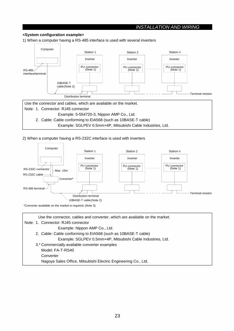
<System configuration example>1) When a computer having a RS-485 interface is used with several inverters
Computer
Inverter
Station 1
RS-485 interface/terminal
10BASE-T cable
Terminal resistorDistribution terminal
(Note 2)
PU connector(Note 1)
Inverter
Station 2
PU connector(Note 1)
Inverter
Station n
PU connector(Note 1)
Use the connector and cables, which are available on the market.Note: 1. Connector: RJ45 connector
Example: 5-554720-3, Nippon AMP Co., Ltd.2. Cable: Cable conforming to EIA568 (such as 10BASE-T cable)
Example: SGLPEV 0.5mm×4P, Mitsubishi Cable Industries, Ltd.
2) When a computer having a RS-232C interface is used with inverters
Computer
Terminal resistor
Max. 15mRS-232C connector
RS-485 terminal
Converter*
10BASE-T cableDistribution terminal
RS-232C cable
*Converter available on the market is required. (Note 3)
(Note 2)
Inverter
Station 1
PU connector(Note 1)
Inverter
Station 2
PU connector(Note 1)
Inverter
Station n
PU connector(Note 1)
Use the connector, cables and converter, which are available on the market.Note: 1. Connector: RJ45 connector
Example: Nippon AMP Co., Ltd.2. Cable: Cable conforming to EIA568 (such as 10BASE-T cable)
Example: SGLPEV 0.5mm×4P, Mitsubishi Cable Industries, Ltd.3.* Commercially available converter examples
Model: FA-T-RS40ConverterNagoya Sales Office, Mitsubishi Electric Engineering Co., Ltd.
INSTALLATION AND WIRING
24
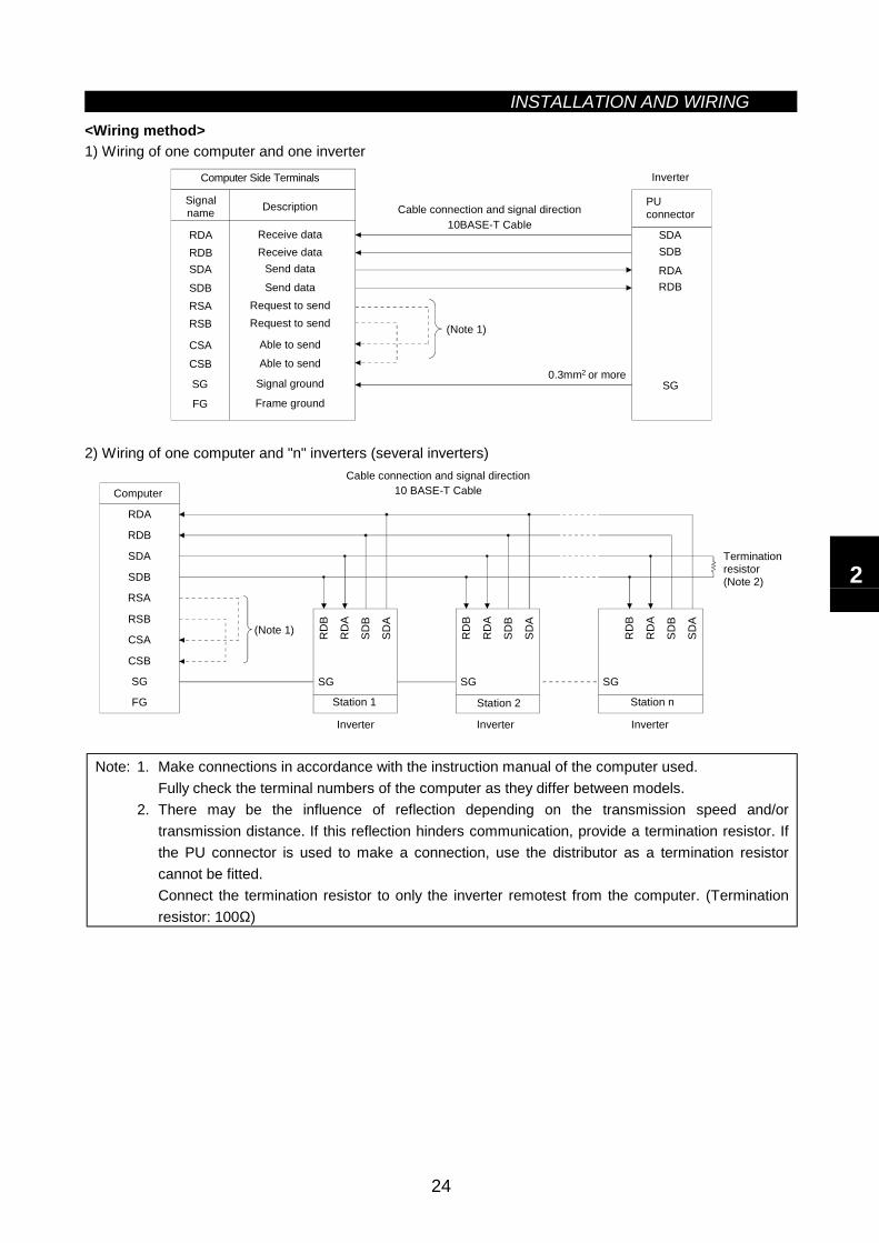
<Wiring method>1) Wiring of one computer and one inverter
Computer Side Terminals
Signalname Description
RDARDBSDA
SDBRSARSB
CSACSB
SG
FG
Receive dataReceive data
Send data
Send dataRequest to sendRequest to send
Able to send
Able to send
Signal ground
Frame ground
PUconnector
SDASDB
RDARDB
SG
(Note 1)
0.3mm or more2
Cable connection and signal direction10BASE-T Cable
Inverter
2) Wiring of one computer and "n" inverters (several inverters)
(Note 1)
Computer
Station 1 Station 2 Station n
Inverter Inverter Inverter
Termination resistor(Note 2)
Cable connection and signal direction10 BASE-T Cable
SDB
SDA
RDB
RDA
FG
SG
CSB
CSA
RSB
RSA
SG
RD
B
RD
A
SDB
SDA
SG
RD
B
RD
A
SDB
SDA
SG
RD
B
RD
A
SDB
SDA
Note: 1. Make connections in accordance with the instruction manual of the computer used.Fully check the terminal numbers of the computer as they differ between models.
2. There may be the influence of reflection depending on the transmission speed and/ortransmission distance. If this reflection hinders communication, provide a termination resistor. Ifthe PU connector is used to make a connection, use the distributor as a termination resistorcannot be fitted.Connect the termination resistor to only the inverter remotest from the computer. (Terminationresistor: 100Ω)
2
INSTALLATION AND WIRING
25
2.2.5 Connection of stand-alone option units
The inverter accepts a variety of stand-alone option units as required.Incorrect connection will cause inverter damage or accident. Connect and operate the option unit carefully inaccordance with the corresponding option unit manual.
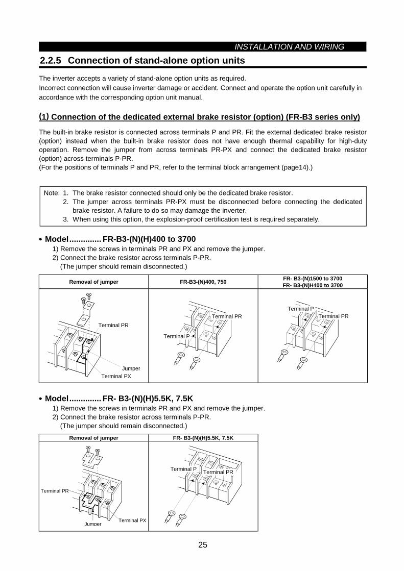
(1) Connection of the dedicated external brake resistor (option) (FR-B3 series only)
The built-in brake resistor is connected across terminals P and PR. Fit the external dedicated brake resistor(option) instead when the built-in brake resistor does not have enough thermal capability for high-dutyoperation. Remove the jumper from across terminals PR-PX and connect the dedicated brake resistor(option) across terminals P-PR.(For the positions of terminals P and PR, refer to the terminal block arrangement (page14).)
Note: 1. The brake resistor connected should only be the dedicated brake resistor.2. The jumper across terminals PR-PX must be disconnected before connecting the dedicated
brake resistor. A failure to do so may damage the inverter.3. When using this option, the explosion-proof certification test is required separately.
•••• Model.............. FR-B3-(N)(H)400 to 37001) Remove the screws in terminals PR and PX and remove the jumper.2) Connect the brake resistor across terminals P-PR.
(The jumper should remain disconnected.)
Removal of jumper FR-B3-(N)400, 750 FR- B3-(N)1500 to 3700FR- B3-(N)H400 to 3700
Terminal PX
Terminal PR
Jumper
Terminal PR
Terminal P
Terminal PRTerminal P
•••• Model.............. FR- B3-(N)(H)5.5K, 7.5K1) Remove the screws in terminals PR and PX and remove the jumper.2) Connect the brake resistor across terminals P-PR.
(The jumper should remain disconnected.)
Removal of jumper FR- B3-(N)(H)5.5K, 7.5K
Jumper
Terminal PR
Terminal PX
Terminal PRTerminal P
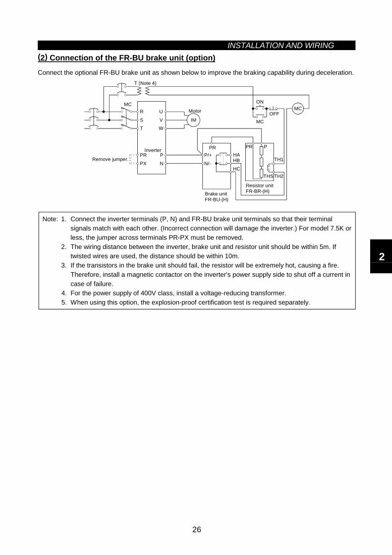
INSTALLATION AND WIRING
26
(2) Connection of the FR-BU brake unit (option)
Connect the optional FR-BU brake unit as shown below to improve the braking capability during deceleration.
MCR
ST
U
VW
P
N
PR
PX
IM
PRP/+
N/-
HAHB
HC
Brake unitFR-BU-(H)
Resistor unitFR-BR-(H)
THS TH2
TH1
PPR
ON
MCOFF
MC
Remove jumper.
Inverter
Motor
T (Note 4)
Note: 1. Connect the inverter terminals (P, N) and FR-BU brake unit terminals so that their terminalsignals match with each other. (Incorrect connection will damage the inverter.) For model 7.5K orless, the jumper across terminals PR-PX must be removed.
2. The wiring distance between the inverter, brake unit and resistor unit should be within 5m. Iftwisted wires are used, the distance should be within 10m.
3. If the transistors in the brake unit should fail, the resistor will be extremely hot, causing a fire.Therefore, install a magnetic contactor on the inverter's power supply side to shut off a current incase of failure.
4. For the power supply of 400V class, install a voltage-reducing transformer.5. When using this option, the explosion-proof certification test is required separately.
2
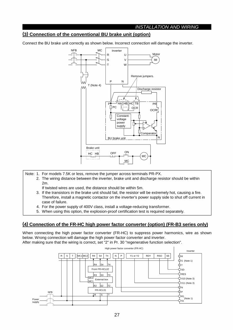
INSTALLATION AND WIRING
27
(3) Connection of the conventional BU brake unit (option)
Connect the BU brake unit correctly as shown below. Incorrect connection will damage the inverter.
MCR
ST
U
VW
IM
Inverter
HCHBHA TB
HC HB ON
MCMC
OFF
P N
POCR
PR
OCR
N
NFB
PC
Brake unit
Remove jumpers.
Discharge resistor
Constant-voltagepowersupply
BU brake unitComparator
Motor
T (Note 4)
+-
Note: 1. For models 7.5K or less, remove the jumper across terminals PR-PX.2. The wiring distance between the inverter, brake unit and discharge resistor should be within
2m.If twisted wires are used, the distance should be within 5m.
3. If the transistors in the brake unit should fail, the resistor will be extremely hot, causing a fire.Therefore, install a magnetic contactor on the inverter's power supply side to shut off current incase of failure.
4. For the power supply of 400V class, install a voltage-reducing transformer.5. When using this option, the explosion-proof certification test is required separately.
(4) Connection of the FR-HC high power factor converter (option) (FR-B3 series only)When connecting the high power factor converter (FR-HC) to suppress power harmonics, wire as shownbelow. Wrong connection will damage the high power factor converter and inverter.After making sure that the wiring is correct, set "2" in Pr. 30 "regenerative function selection".
X10 (Note 3)
X11 (Note 3)
N
P
R1
S1
RES
SD
T
S (Note 1)
R
NFB
R S T R4 S4 T4 N P Y1 or Y2 RDY RSO SE
Inverter
(Note 1)
High power factor converter (FR-HC)
From FR-HCL02
Powersupply
MC1 MC2
External boxMC1MC2
FR-HCL01
R4 S4 T4
R3 S3 T3
R2 S2 T2
R S T
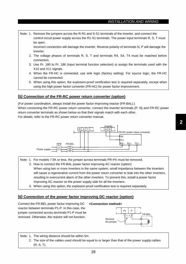
INSTALLATION AND WIRING
28
Note: 1. Remove the jumpers across the R-R1 and S-S1 terminals of the inverter, and connect thecontrol circuit power supply across the R1-S1 terminals. The power input terminals R, S, T mustbe open.Incorrect connection will damage the inverter. Reverse polarity of terminals N, P will damage theinverter.
2. The voltage phases of terminals R, S, T and terminals R4, S4, T4 must be matched beforeconnection.
3. Use Pr. 180 to Pr. 186 (input terminal function selection) to assign the terminals used with theX10 and X11 signals.
4. When the FR-HC is connected, use sink logic (factory setting). For source logic, the FR-HCcannot be connected.
5. When using this option, the explosion-proof certification test is required separately, except whenusing the high power factor converter (FR-HC) for power factor improvement.
(5) Connection of the FR-RC power return converter (option)
(For power coordination, always install the power factor-improving reactor (FR-BAL).)When connecting the FR-RC power return converter, connect the inverter terminals (P, N) and FR-RC powerreturn converter terminals as shown below so that their signals match with each other.For details, refer to the FR-RC power return converter manual.
N P
NFB FR-BAL R/L1 S/L2 T/L3
P/+N/-
FR-RC power return converter
Power supply
InverterR S T
Note: 1. For models 7.5K or less, the jumper across terminals PR-PX must be removed.2. How to connect the FR-BAL power factor improving AC reactor (option)
When using two or more inverters in the same system, small impedance between the inverterswill cause a regenerative current from the power return converter to leak into the other inverters,resulting in overcurrent alarm of the other inverters. To prevent this, install a power factorimproving AC reactor on the power supply side for all the inverters.
3. When using this option, the explosion-proof certification test is required separately.
(6) Connection of the power factor improving DC reactor (option)
Connect the FR-BEL power factor improving DCreactor between terminals P1-P. In this case, thejumper connected across terminals P1-P must beremoved. Otherwise, the reactor will not function.
<Connection method>
P1 PFR-BEL
Remove the jumper.
Note: 1. The wiring distance should be within 5m.2. The size of the cables used should be equal to or larger than that of the power supply cables
(R, S, T).
2
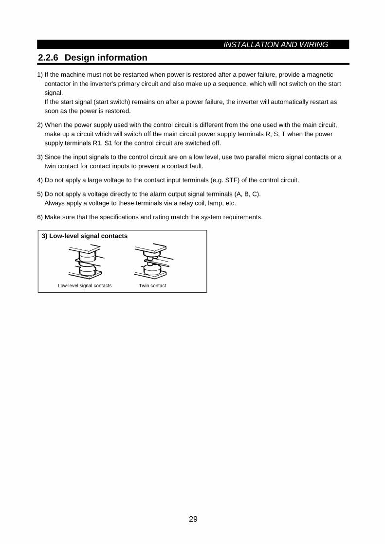
INSTALLATION AND WIRING
29
2.2.6 Design information
1) If the machine must not be restarted when power is restored after a power failure, provide a magneticcontactor in the inverter's primary circuit and also make up a sequence, which will not switch on the startsignal.If the start signal (start switch) remains on after a power failure, the inverter will automatically restart assoon as the power is restored.
2) When the power supply used with the control circuit is different from the one used with the main circuit,make up a circuit which will switch off the main circuit power supply terminals R, S, T when the powersupply terminals R1, S1 for the control circuit are switched off.
3) Since the input signals to the control circuit are on a low level, use two parallel micro signal contacts or atwin contact for contact inputs to prevent a contact fault.
4) Do not apply a large voltage to the contact input terminals (e.g. STF) of the control circuit.
5) Do not apply a voltage directly to the alarm output signal terminals (A, B, C).Always apply a voltage to these terminals via a relay coil, lamp, etc.
6) Make sure that the specifications and rating match the system requirements.
3) Low-level signal contacts
Twin contactLow-level signal contacts
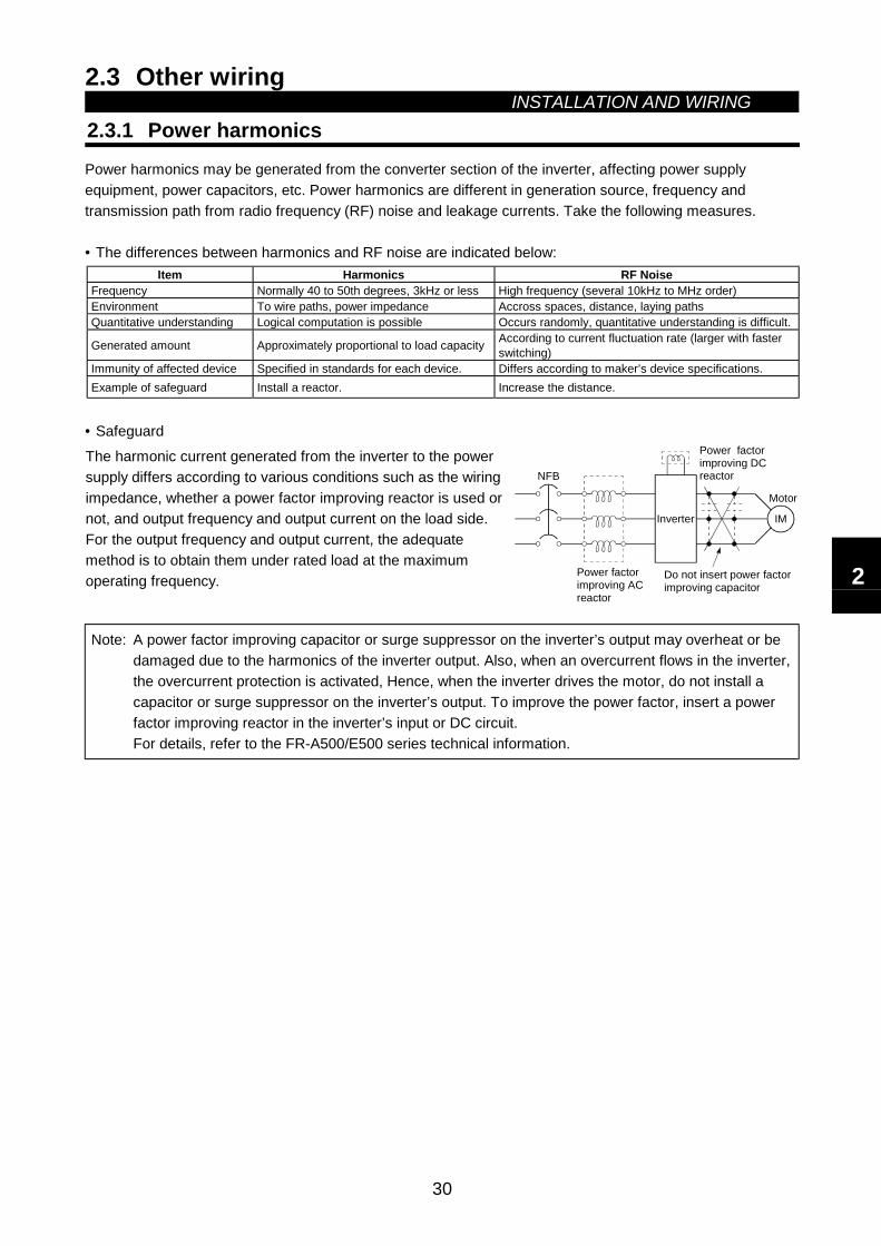
2.3 Other wiringINSTALLATION AND WIRING
30
2.3 Other Wiring
2.3.1 Power harmonicsPower harmonics may be generated from the converter section of the inverter, affecting power supplyequipment, power capacitors, etc. Power harmonics are different in generation source, frequency andtransmission path from radio frequency (RF) noise and leakage currents. Take the following measures.
• The differences between harmonics and RF noise are indicated below:Item Harmonics RF Noise
Frequency Normally 40 to 50th degrees, 3kHz or less High frequency (several 10kHz to MHz order)Environment To wire paths, power impedance Accross spaces, distance, laying pathsQuantitative understanding Logical computation is possible Occurs randomly, quantitative understanding is difficult.
Generated amount Approximately proportional to load capacity According to current fluctuation rate (larger with fasterswitching)
Immunity of affected device Specified in standards for each device. Differs according to maker’s device specifications.Example of safeguard Install a reactor. Increase the distance.
• Safeguard
The harmonic current generated from the inverter to the powersupply differs according to various conditions such as the wiringimpedance, whether a power factor improving reactor is used ornot, and output frequency and output current on the load side.For the output frequency and output current, the adequatemethod is to obtain them under rated load at the maximumoperating frequency.
NFB
IMInverter
Power factorimproving DCreactor
Motor
Do not insert power factor improving capacitor
Power factorimproving ACreactor
Note: A power factor improving capacitor or surge suppressor on the inverter’s output may overheat or bedamaged due to the harmonics of the inverter output. Also, when an overcurrent flows in the inverter,the overcurrent protection is activated, Hence, when the inverter drives the motor, do not install acapacitor or surge suppressor on the inverter’s output. To improve the power factor, insert a powerfactor improving reactor in the inverter’s input or DC circuit.For details, refer to the FR-A500/E500 series technical information.
2
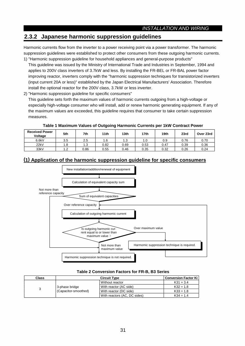
INSTALLATION AND WIRING
31
2.3.2 Japanese harmonic suppression guidelines
Harmonic currents flow from the inverter to a power receiving point via a power transformer. The harmonicsuppression guidelines were established to protect other consumers from these outgoing harmonic currents.1) "Harmonic suppression guideline for household appliances and general-purpose products"
This guideline was issued by the Ministry of International Trade and Industries in September, 1994 andapplies to 200V class inverters of 3.7kW and less. By installing the FR-BEL or FR-BAL power factorimproving reactor, inverters comply with the "harmonic suppression techniques for transistorized inverters(input current 20A or less)" established by the Japan Electrical Manufacturers' Association. Thereforeinstall the optional reactor for the 200V class, 3.7kW or less inverter.
2) "Harmonic suppression guideline for specific consumers"This guideline sets forth the maximum values of harmonic currents outgoing from a high-voltage orespecially high-voltage consumer who will install, add or renew harmonic generating equipment. If any ofthe maximum values are exceeded, this guideline requires that consumer to take certain suppressionmeasures.
Table 1 Maximum Values of Outgoing Harmonic Currents per 1kW Contract PowerReceived Power
Voltage 5th 7th 11th 13th 17th 19th 23rd Over 23rd
6.6kV 3.5 2.5 1.6 1.3 1.0 0.9 0.76 0.7022kV 1.8 1.3 0.82 0.69 0.53 0.47 0.39 0.3633kV 1.2 0.86 0.55 0.46 0.35 0.32 0.26 0.24
(1) Application of the harmonic suppression guideline for specific consumersNew installation/addition/renewal of equipment
Sum of equivalent capacities
Over reference capacity
Is outgoing harmonic cur-rent equal to or lower than
maximum value ?
Over maximum value
Not more thanmaximum value
Not more thanreference capacity
Calculation of equivalent capacity sum
Calculation of outgoing harmomic current
Harmomic suppression technique is required.
Harmomic suppression technique is not required.
Table 2 Conversion Factors for FR-B, B3 SeriesClass Circuit Type Conversion Factor Ki
Without reactor K31 = 3.4With reactor (AC side) K32 = 1.8With reactor (DC side) K33 = 1.83 3-phase bridge
(Capacitor-smoothed)With reactors (AC, DC sides) K34 = 1.4
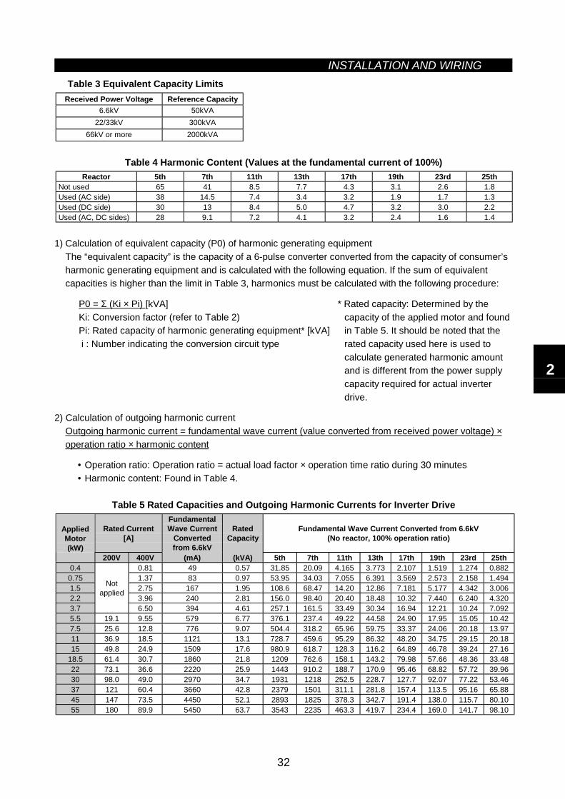
INSTALLATION AND WIRING
32
Table 3 Equivalent Capacity LimitsReceived Power Voltage Reference Capacity
6.6kV 50kVA22/33kV 300kVA
66kV or more 2000kVA
Table 4 Harmonic Content (Values at the fundamental current of 100%)Reactor 5th 7th 11th 13th 17th 19th 23rd 25th
Not used 65 41 8.5 7.7 4.3 3.1 2.6 1.8Used (AC side) 38 14.5 7.4 3.4 3.2 1.9 1.7 1.3Used (DC side) 30 13 8.4 5.0 4.7 3.2 3.0 2.2Used (AC, DC sides) 28 9.1 7.2 4.1 3.2 2.4 1.6 1.4
1) Calculation of equivalent capacity (P0) of harmonic generating equipmentThe “equivalent capacity” is the capacity of a 6-pulse converter converted from the capacity of consumer’sharmonic generating equipment and is calculated with the following equation. If the sum of equivalentcapacities is higher than the limit in Table 3, harmonics must be calculated with the following procedure:
P0 = Σ (Ki × Pi) [kVA]Ki: Conversion factor (refer to Table 2)Pi: Rated capacity of harmonic generating equipment* [kVA] i : Number indicating the conversion circuit type
* Rated capacity: Determined by thecapacity of the applied motor and foundin Table 5. It should be noted that therated capacity used here is used tocalculate generated harmonic amountand is different from the power supplycapacity required for actual inverterdrive.
2) Calculation of outgoing harmonic currentOutgoing harmonic current = fundamental wave current (value converted from received power voltage) ×operation ratio × harmonic content
• Operation ratio: Operation ratio = actual load factor × operation time ratio during 30 minutes• Harmonic content: Found in Table 4.
Table 5 Rated Capacities and Outgoing Harmonic Currents for Inverter Drive
Rated Current[A]
FundamentalWave Current
Convertedfrom 6.6kV
RatedCapacity
Fundamental Wave Current Converted from 6.6kV(No reactor, 100% operation ratio)
AppliedMotor(kW)
200V 400V (mA) (kVA) 5th 7th 11th 13th 17th 19th 23rd 25th0.4 0.81 49 0.57 31.85 20.09 4.165 3.773 2.107 1.519 1.274 0.8820.75 1.37 83 0.97 53.95 34.03 7.055 6.391 3.569 2.573 2.158 1.4941.5 2.75 167 1.95 108.6 68.47 14.20 12.86 7.181 5.177 4.342 3.0062.2 3.96 240 2.81 156.0 98.40 20.40 18.48 10.32 7.440 6.240 4.3203.7
Notapplied
6.50 394 4.61 257.1 161.5 33.49 30.34 16.94 12.21 10.24 7.0925.5 19.1 9.55 579 6.77 376.1 237.4 49.22 44.58 24.90 17.95 15.05 10.427.5 25.6 12.8 776 9.07 504.4 318.2 65.96 59.75 33.37 24.06 20.18 13.9711 36.9 18.5 1121 13.1 728.7 459.6 95.29 86.32 48.20 34.75 29.15 20.1815 49.8 24.9 1509 17.6 980.9 618.7 128.3 116.2 64.89 46.78 39.24 27.16
18.5 61.4 30.7 1860 21.8 1209 762.6 158.1 143.2 79.98 57.66 48.36 33.4822 73.1 36.6 2220 25.9 1443 910.2 188.7 170.9 95.46 68.82 57.72 39.9630 98.0 49.0 2970 34.7 1931 1218 252.5 228.7 127.7 92.07 77.22 53.4637 121 60.4 3660 42.8 2379 1501 311.1 281.8 157.4 113.5 95.16 65.8845 147 73.5 4450 52.1 2893 1825 378.3 342.7 191.4 138.0 115.7 80.1055 180 89.9 5450 63.7 3543 2235 463.3 419.7 234.4 169.0 141.7 98.10
2
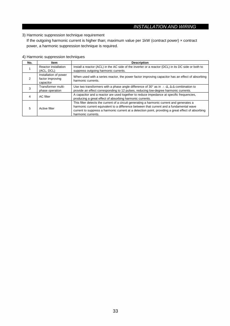
INSTALLATION AND WIRING
33
3) Harmonic suppression technique requirementIf the outgoing harmonic current is higher than; maximum value per 1kW (contract power) × contractpower, a harmonic suppression technique is required.
4) Harmonic suppression techniquesNo. Item Description
1 Reactor installation(ACL, DCL)
Install a reactor (ACL) in the AC side of the inverter or a reactor (DCL) in its DC side or both tosuppress outgoing harmonic currents.
2Installation of powerfactor improvingcapacitor
When used with a series reactor, the power factor improving capacitor has an effect of absorbingharmonic currents.
3 Transformer multi-phase operation
Use two transformers with a phase angle difference of 30° as in -∆, ∆-∆ combination toprovide an effect corresponding to 12 pulses, reducing low-degree harmonic currents.
4 AC filter A capacitor and a reactor are used together to reduce impedance at specific frequencies,producing a great effect of absorbing harmonic currents.
5 Active filter
This filter detects the current of a circuit generating a harmonic current and generates aharmonic current equivalent to a difference between that current and a fundamental wavecurrent to suppress a harmonic current at a detection point, providing a great effect of absorbingharmonic currents.
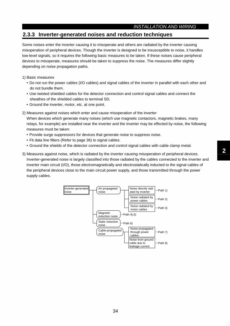
INSTALLATION AND WIRING
34
2.3.3 Inverter-generated noises and reduction techniques
Some noises enter the inverter causing it to misoperate and others are radiated by the inverter causingmisoperation of peripheral devices. Though the inverter is designed to be insusceptible to noise, it handleslow-level signals, so it requires the following basic measures to be taken. If these noises cause peripheraldevices to misoperate, measures should be taken to suppress the noise. The measures differ slightlydepending on noise propagation paths.
1) Basic measures• Do not run the power cables (I/O cables) and signal cables of the inverter in parallel with each other and do not bundle them.• Use twisted shielded cables for the detector connection and control signal cables and connect the sheathes of the shielded cables to terminal SD.• Ground the inverter, motor, etc. at one point.
2) Measures against noises which enter and cause misoperation of the inverterWhen devices which generate many noises (which use magnetic contactors, magnetic brakes, manyrelays, for example) are installed near the inverter and the inverter may be effected by noise, the followingmeasures must be taken:• Provide surge suppressors for devices that generate noise to suppress noise.• Fit data line filters (Refer to page 36) to signal cables.• Ground the shields of the detector connection and control signal cables with cable clamp metal.
3) Measures against noise, which is radiated by the inverter causing misoperation of peripheral devices.Inverter-generated noise is largely classified into those radiated by the cables connected to the inverter andinverter main circuit (I/O), those electromagnetically and electrostatically inducted to the signal cables ofthe peripheral devices close to the main circuit power supply, and those transmitted through the powersupply cables.
Air-propagatednoise
Magneticinduction noise
Static inductionnoise
Cable-propagatednoise
Noise directly radi-ated by inverter
Noise radiated bypower cables
Noise radiated bymotor cables
Noise propagatedthrough power cables
Noise from ground cable due to leakage current
Path 4),5)
Path 6)
Path 1)
Path 2)
Path 3)
Path 7)
Path 8)
Inverter-generatednoise
2
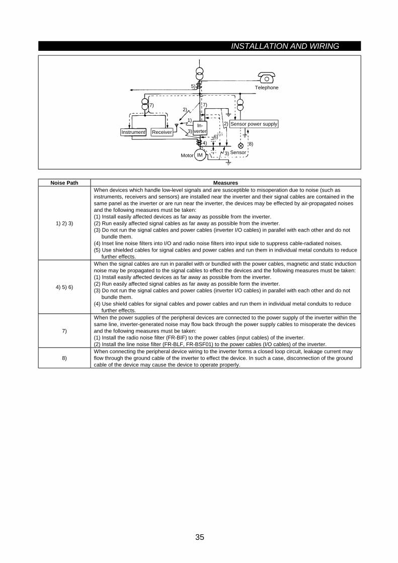
INSTALLATION AND WIRING
35
IM
In-verterInstrument
Telephone
Motor Sensor
5)
7)2)
1)
7)
3)2)
8)
3)
4)6)
ReceiverSensor power supply
Noise Path Measures
1) 2) 3)
When devices which handle low-level signals and are susceptible to misoperation due to noise (such asinstruments, receivers and sensors) are installed near the inverter and their signal cables are contained in thesame panel as the inverter or are run near the inverter, the devices may be effected by air-propagated noisesand the following measures must be taken:(1) Install easily affected devices as far away as possible from the inverter.(2) Run easily affected signal cables as far away as possible from the inverter.(3) Do not run the signal cables and power cables (inverter I/O cables) in parallel with each other and do not
bundle them.(4) Inset line noise filters into I/O and radio noise filters into input side to suppress cable-radiated noises.(5) Use shielded cables for signal cables and power cables and run them in individual metal conduits to reduce
further effects.
4) 5) 6)
When the signal cables are run in parallel with or bundled with the power cables, magnetic and static inductionnoise may be propagated to the signal cables to effect the devices and the following measures must be taken:(1) Install easily affected devices as far away as possible from the inverter.(2) Run easily affected signal cables as far away as possible form the inverter.(3) Do not run the signal cables and power cables (inverter I/O cables) in parallel with each other and do not
bundle them.(4) Use shield cables for signal cables and power cables and run them in individual metal conduits to reduce
further effects.
7)
When the power supplies of the peripheral devices are connected to the power supply of the inverter within thesame line, inverter-generated noise may flow back through the power supply cables to misoperate the devicesand the following measures must be taken:(1) Install the radio noise filter (FR-BIF) to the power cables (input cables) of the inverter.(2) Install the line noise filter (FR-BLF, FR-BSF01) to the power cables (I/O cables) of the inverter.
8)When connecting the peripheral device wiring to the inverter forms a closed loop circuit, leakage current mayflow through the ground cable of the inverter to effect the device. In such a case, disconnection of the groundcable of the device may cause the device to operate properly.
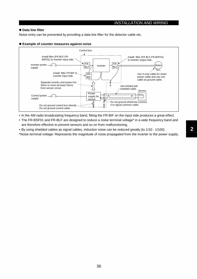
INSTALLATION AND WIRING
36
Data line filterNoise entry can be prevented by providing a data line filter for the detector cable etc.
Example of counter measures against noise
FR-BLF
FR-BIF
FR-BLF
Install filter (FR-BLF,FR-BSF01) to inverter input side.
Control box
Install filter (FR-BLF,FR-BSF01)to inverter output side.
Use 4-core cable for motorpower cable and use onecable as ground cable.
Use twisted pairshielded cable.
Sensor
Do not ground shield but connectit to signal common cable.Do not ground control box directly.
Control powersupply
Separate inverter and power line 30cm or more (at least 10cm) from sensor circuit.
Install filter FR-BIF toinverter input side.
Inverter powersupply
Powersupply forsensor
Inverter Motor
Do not ground control cable.
• In the AM radio broadcasting frequency band, fitting the FR-BIF on the input side produces a great effect.• The FR-BSF01 and FR-BLF are designed to reduce a noise terminal voltage* in a wide frequency band and
are therefore effective to prevent sensors and so on from malfunctioning.• By using shielded cables as signal cables, induction noise can be reduced greatly (to 1/10 - 1/100).*Noise terminal voltage: Represents the magnitude of noise propagated from the inverter to the power supply.
2
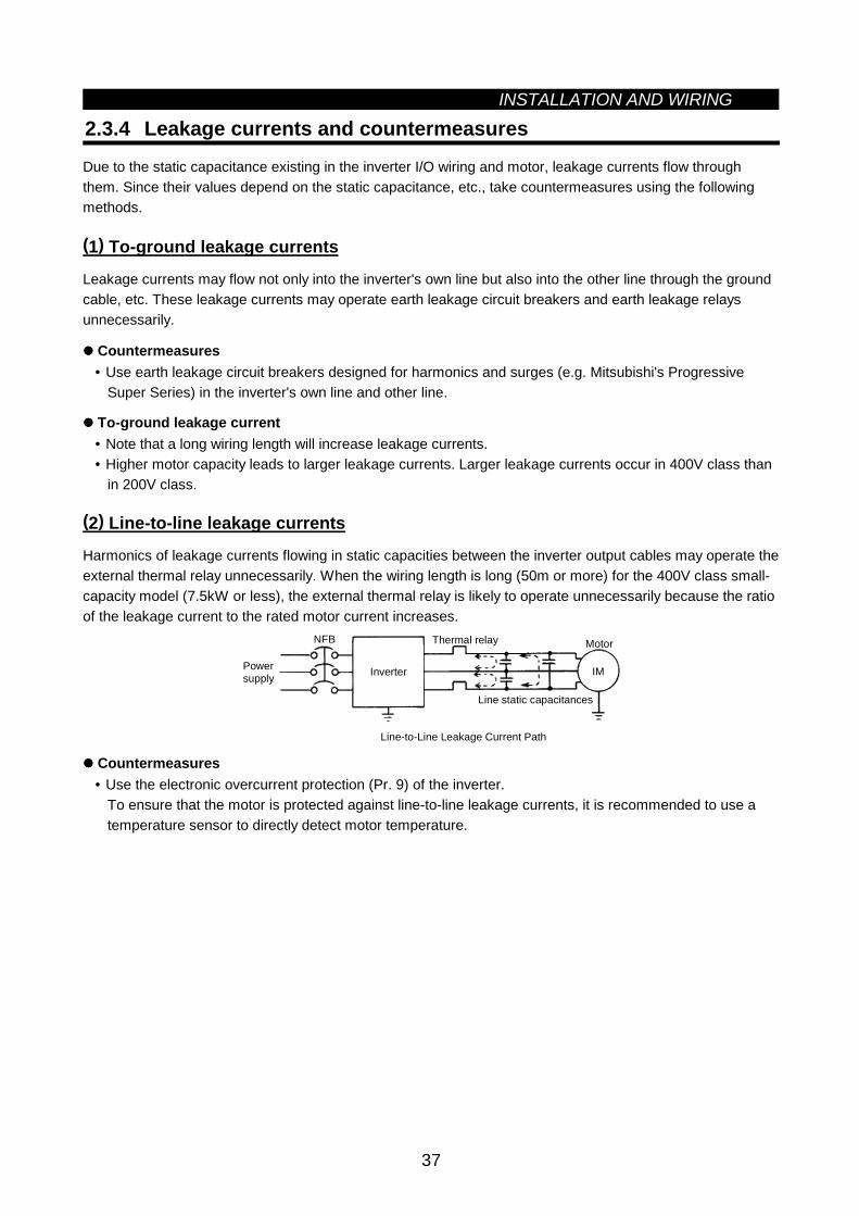
INSTALLATION AND WIRING
37
2.3.4 Leakage currents and countermeasures
Due to the static capacitance existing in the inverter I/O wiring and motor, leakage currents flow throughthem. Since their values depend on the static capacitance, etc., take countermeasures using the followingmethods.
(1) To-ground leakage currents
Leakage currents may flow not only into the inverter's own line but also into the other line through the groundcable, etc. These leakage currents may operate earth leakage circuit breakers and earth leakage relaysunnecessarily.
Countermeasures• Use earth leakage circuit breakers designed for harmonics and surges (e.g. Mitsubishi's Progressive
Super Series) in the inverter's own line and other line.
To-ground leakage current• Note that a long wiring length will increase leakage currents.• Higher motor capacity leads to larger leakage currents. Larger leakage currents occur in 400V class than
in 200V class.
(2) Line-to-line leakage currents
Harmonics of leakage currents flowing in static capacities between the inverter output cables may operate theexternal thermal relay unnecessarily. When the wiring length is long (50m or more) for the 400V class small-capacity model (7.5kW or less), the external thermal relay is likely to operate unnecessarily because the ratioof the leakage current to the rated motor current increases.
IM
NFB
Line-to-Line Leakage Current Path
Power supply Inverter
Thermal relay
Line static capacitances
Motor
Countermeasures• Use the electronic overcurrent protection (Pr. 9) of the inverter.
To ensure that the motor is protected against line-to-line leakage currents, it is recommended to use atemperature sensor to directly detect motor temperature.
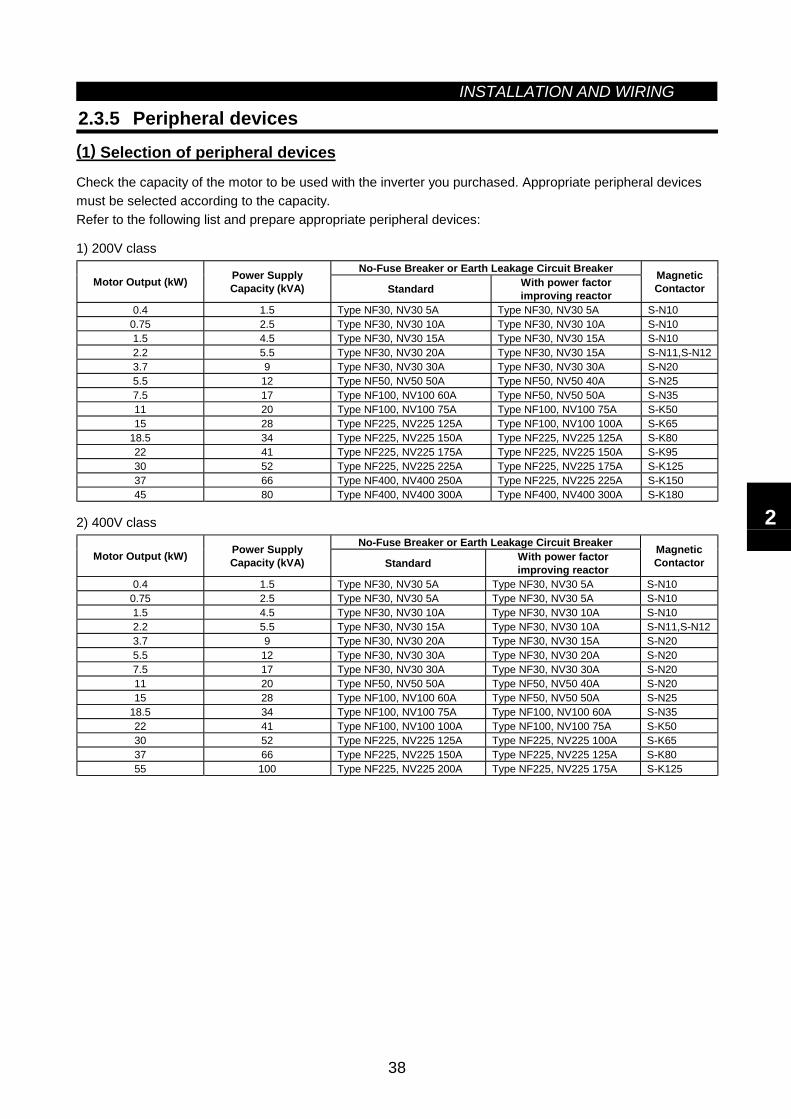
INSTALLATION AND WIRING
38
2.3.5 Peripheral devices(1) Selection of peripheral devices
Check the capacity of the motor to be used with the inverter you purchased. Appropriate peripheral devicesmust be selected according to the capacity.Refer to the following list and prepare appropriate peripheral devices:
1) 200V classNo-Fuse Breaker or Earth Leakage Circuit Breaker
Motor Output (kW) Power SupplyCapacity (kVA) Standard With power factor
improving reactor
MagneticContactor
0.4 1.5 Type NF30, NV30 5A Type NF30, NV30 5A S-N100.75 2.5 Type NF30, NV30 10A Type NF30, NV30 10A S-N101.5 4.5 Type NF30, NV30 15A Type NF30, NV30 15A S-N102.2 5.5 Type NF30, NV30 20A Type NF30, NV30 15A S-N11,S-N123.7 9 Type NF30, NV30 30A Type NF30, NV30 30A S-N205.5 12 Type NF50, NV50 50A Type NF50, NV50 40A S-N257.5 17 Type NF100, NV100 60A Type NF50, NV50 50A S-N3511 20 Type NF100, NV100 75A Type NF100, NV100 75A S-K5015 28 Type NF225, NV225 125A Type NF100, NV100 100A S-K65
18.5 34 Type NF225, NV225 150A Type NF225, NV225 125A S-K8022 41 Type NF225, NV225 175A Type NF225, NV225 150A S-K9530 52 Type NF225, NV225 225A Type NF225, NV225 175A S-K12537 66 Type NF400, NV400 250A Type NF225, NV225 225A S-K15045 80 Type NF400, NV400 300A Type NF400, NV400 300A S-K180
2) 400V classNo-Fuse Breaker or Earth Leakage Circuit Breaker
Motor Output (kW) Power SupplyCapacity (kVA) Standard With power factor
improving reactor
MagneticContactor
0.4 1.5 Type NF30, NV30 5A Type NF30, NV30 5A S-N100.75 2.5 Type NF30, NV30 5A Type NF30, NV30 5A S-N101.5 4.5 Type NF30, NV30 10A Type NF30, NV30 10A S-N102.2 5.5 Type NF30, NV30 15A Type NF30, NV30 10A S-N11,S-N123.7 9 Type NF30, NV30 20A Type NF30, NV30 15A S-N205.5 12 Type NF30, NV30 30A Type NF30, NV30 20A S-N207.5 17 Type NF30, NV30 30A Type NF30, NV30 30A S-N2011 20 Type NF50, NV50 50A Type NF50, NV50 40A S-N2015 28 Type NF100, NV100 60A Type NF50, NV50 50A S-N25
18.5 34 Type NF100, NV100 75A Type NF100, NV100 60A S-N3522 41 Type NF100, NV100 100A Type NF100, NV100 75A S-K5030 52 Type NF225, NV225 125A Type NF225, NV225 100A S-K6537 66 Type NF225, NV225 150A Type NF225, NV225 125A S-K8055 100 Type NF225, NV225 200A Type NF225, NV225 175A S-K125
2
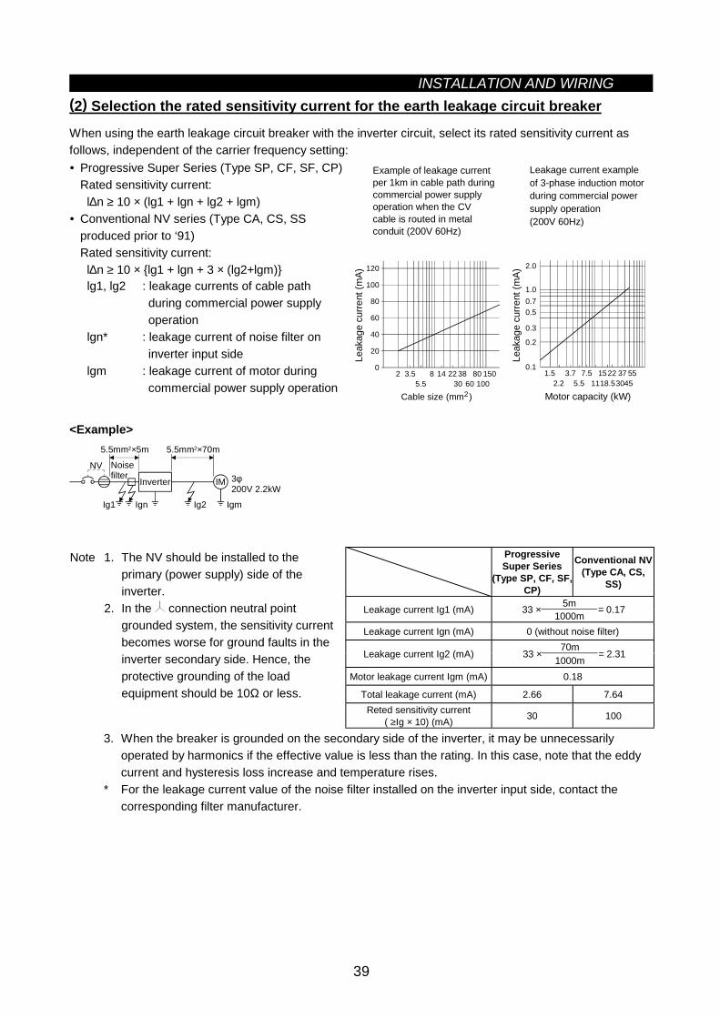
INSTALLATION AND WIRING
39
(2) Selection the rated sensitivity current for the earth leakage circuit breaker
When using the earth leakage circuit breaker with the inverter circuit, select its rated sensitivity current asfollows, independent of the carrier frequency setting:• Progressive Super Series (Type SP, CF, SF, CP)
Rated sensitivity current: l∆n ≥ 10 × (lg1 + lgn + lg2 + lgm)
• Conventional NV series (Type CA, CS, SSproduced prior to ‘91)Rated sensitivity current: l∆n ≥ 10 × lg1 + lgn + 3 × (lg2+lgm)
lg1, lg2 : leakage currents of cable pathduring commercial power supplyoperation
lgn* : leakage current of noise filter oninverter input side
lgm : leakage current of motor duringcommercial power supply operation
Leakage current exampleof 3-phase induction motorduring commercial powersupply operation(200V 60Hz)
0
20
40
60
80
100
120
2 3.55.5
8 14 2230
3860
80100
150
Leak
age
curre
nt (m
A)
Cable size (mm )2
0.11.5 3.7
2.27.5 1522
1137
3055
45
0.2
0.3
0.50.71.0
2.0
5.5 18.5
Motor capacity (kW)
Example of leakage current per 1km in cable path during commercial power supplyoperation when the CV cable is routed in metal conduit (200V 60Hz)
Leak
age
curre
nt (m
A)
<Example>
NV
Ig1 Ign Ig2 Igm
5.5mm2×5m 5.5mm2×70m
IM 3φ200V 2.2kW
Inverter
Noisefilter
ProgressiveSuper Series
(Type SP, CF, SF,CP)
Conventional NV(Type CA, CS,
SS)
5mLeakage current Ig1 (mA) 33 × 1000m = 0.17
Leakage current Ign (mA) 0 (without noise filter)70m
Leakage current Ig2 (mA) 33 ×1000m
= 2.31
Motor leakage current Igm (mA) 0.18
Total leakage current (mA) 2.66 7.64Reted sensitivity current
( ≥Ig × 10) (mA) 30 100
Note 1. The NV should be installed to theprimary (power supply) side of theinverter.
2. In the connection neutral pointgrounded system, the sensitivity currentbecomes worse for ground faults in theinverter secondary side. Hence, theprotective grounding of the loadequipment should be 10Ω or less.
3. When the breaker is grounded on the secondary side of the inverter, it may be unnecessarilyoperated by harmonics if the effective value is less than the rating. In this case, note that the eddycurrent and hysteresis loss increase and temperature rises.
* For the leakage current value of the noise filter installed on the inverter input side, contact thecorresponding filter manufacturer.
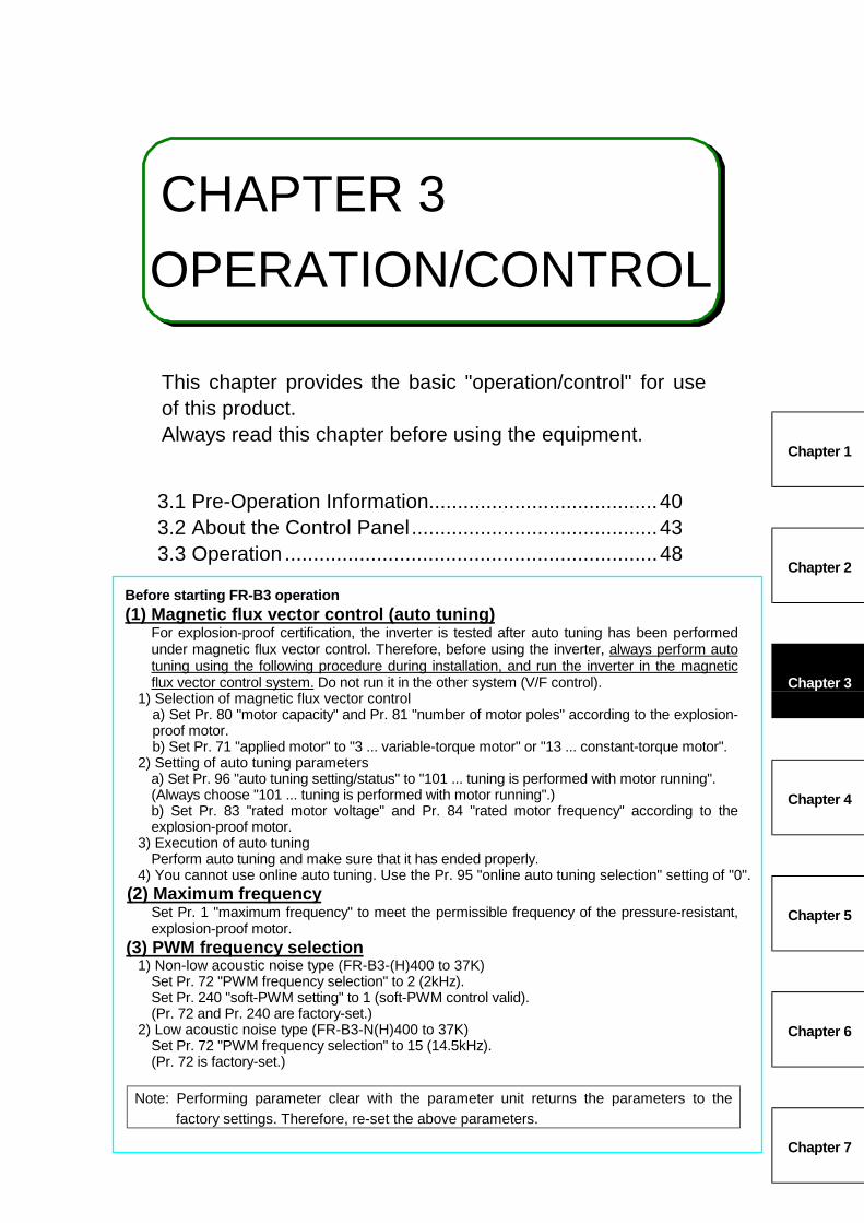
3
CHAPTER 3OPERATION/CONTROL
This chapter provides the basic "operation/control" for useof this product.Always read this chapter before using the equipment.
3.1 Pre-Operation Information........................................40 3.2 About the Control Panel...........................................43 3.3 Operation .................................................................48
Before starting FR-B3 operation(1) Magnetic flux vector control (auto tuning)
For explosion-proof certification, the inverter is tested after auto tuning has been performedunder magnetic flux vector control. Therefore, before using the inverter, always perform autotuning using the following procedure during installation, and run the inverter in the magneticflux vector control system. Do not run it in the other system (V/F control).
1) Selection of magnetic flux vector controla) Set Pr. 80 "motor capacity" and Pr. 81 "number of motor poles" according to the explosion-proof motor.b) Set Pr. 71 "applied motor" to "3 ... variable-torque motor" or "13 ... constant-torque motor".
2) Setting of auto tuning parametersa) Set Pr. 96 "auto tuning setting/status" to "101 ... tuning is performed with motor running".(Always choose "101 ... tuning is performed with motor running".)b) Set Pr. 83 "rated motor voltage" and Pr. 84 "rated motor frequency" according to theexplosion-proof motor.
3) Execution of auto tuningPerform auto tuning and make sure that it has ended properly.
4) You cannot use online auto tuning. Use the Pr. 95 "online auto tuning selection" setting of "0".(2) Maximum frequency
Set Pr. 1 "maximum frequency" to meet the permissible frequency of the pressure-resistant,explosion-proof motor.
(3) PWM frequency selection1) Non-low acoustic noise type (FR-B3-(H)400 to 37K)
Set Pr. 72 "PWM frequency selection" to 2 (2kHz).Set Pr. 240 "soft-PWM setting" to 1 (soft-PWM control valid).(Pr. 72 and Pr. 240 are factory-set.)
2) Low acoustic noise type (FR-B3-N(H)400 to 37K)Set Pr. 72 "PWM frequency selection" to 15 (14.5kHz).(Pr. 72 is factory-set.)
Note: Performing parameter clear with the parameter unit returns the parameters to thefactory settings. Therefore, re-set the above parameters.
Chapter 1
Chapter 2
Chapter 3
Chapter 4
Chapter 5
Chapter 6
Chapter 7
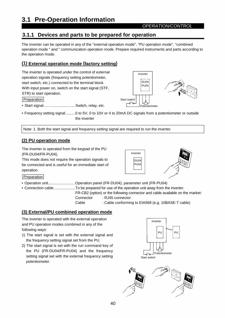
3.1 Pre-Operation InformationOPERATION/CONTROL
40
3 OPERATION/CONTROL3.1 Pre-Operation Information
3.1.1 Devices and parts to be prepared for operationThe inverter can be operated in any of the "external operation mode", "PU operation mode", “combinedoperation mode “ and ” communication operation mode. Prepare required instruments and parts according tothe operation mode.
(1) External operation mode (factory setting)
The inverter is operated under the control of externaloperation signals (frequency setting potentiometer,start switch, etc.) connected to the terminal block.With input power on, switch on the start signal (STF,STR) to start operation.Preparation
• Start signal ..............................Switch, relay, etc.
DU04PU04
Potentiometer
Inverter
Start switch
• Frequency setting signal .........0 to 5V, 0 to 10V or 4 to 20mA DC signals from a potentiometer or outsidethe inverter
Note: 1. Both the start signal and frequency setting signal are required to run the inverter.
(2) PU operation mode
The inverter is operated from the keypad of the PU(FR-DU04/FR-PU04).This mode does not require the operation signals tobe connected and is useful for an immediate start ofoperation.
Preparation
DU04PU04
Inverter
• Operation unit..........................Operation panel (FR-DU04), parameter unit (FR-PU04)• Connection cable ....................To be prepared for use of the operation unit away from the inverter.
FR-CB2 (option) or the following connector and cable available on the market:Connector : RJ45 connectorCable : Cable conforming to EIA568 (e.g. 10BASE-T cable)
(3) External/PU combined operation modeThe inverter is operated with the external operationand PU operation modes combined in any of thefollowing ways:1) The start signal is set with the external signal and
the frequency setting signal set from the PU.2) The start signal is set with the run command key of
the PU (FR-DU04/FR-PU04) and the frequencysetting signal set with the external frequency settingpotentiometer.
PU PU
Potentiometer
Inverter
Start switch
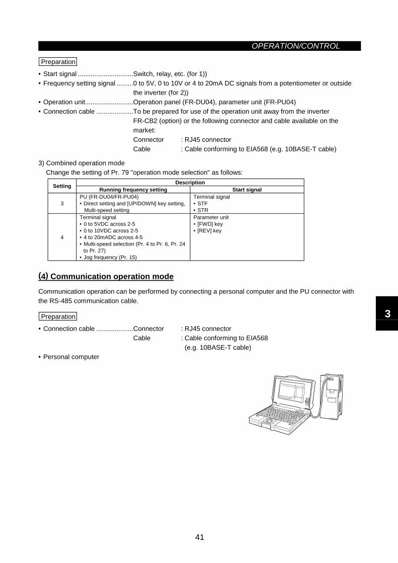
OPERATION/CONTROL
41
Preparation
• Start signal ..............................Switch, relay, etc. (for 1))• Frequency setting signal .........0 to 5V, 0 to 10V or 4 to 20mA DC signals from a potentiometer or outside
the inverter (for 2))• Operation unit..........................Operation panel (FR-DU04), parameter unit (FR-PU04)• Connection cable ....................To be prepared for use of the operation unit away from the inverter
FR-CB2 (option) or the following connector and cable available on themarket:Connector : RJ45 connectorCable : Cable conforming to EIA568 (e.g. 10BASE-T cable)
3) Combined operation modeChange the setting of Pr. 79 "operation mode selection" as follows:
DescriptionSetting Running frequency setting Start signal
3PU (FR-DU04/FR-PU04)• Direct setting and [UP/DOWN] key setting,
Multi-speed setting
Terminal signal• STF• STR
4
Terminal signal• 0 to 5VDC across 2-5• 0 to 10VDC across 2-5• 4 to 20mADC across 4-5• Multi-speed selection (Pr. 4 to Pr. 6, Pr. 24
to Pr. 27)• Jog frequency (Pr. 15)
Parameter unit• [FWD] key• [REV] key
(4) Communication operation mode
Communication operation can be performed by connecting a personal computer and the PU connector withthe RS-485 communication cable.
Preparation
• Connection cable ....................Connector : RJ45 connectorCable : Cable conforming to EIA568
(e.g. 10BASE-T cable)• Personal computer
3
OPERATION/CONTROL
42
3.1.2 Power on
Before switching power on, check the following:
•••• Installation check
Make sure that the inverter is installed correctly in a correct place. (Refer to page 7.)• Wiring check
Make sure that the main and control circuits are wired correctly.Make sure that the options and peripheral devices are selected and connected correctly.(Refer to page 9.)
•••• Switch power on.
Power-on is complete when the POWER lamp is lit correctly and the operation panel (FR-DU04) displayscorrect data.
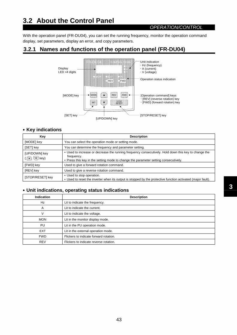
3.2 About the Control PanelOPERATION/CONTROL
43
3.2 About the Control Panel
With the operation panel (FR-DU04), you can set the running frequency, monitor the operation commanddisplay, set parameters, display an error, and copy parameters.
3.2.1 Names and functions of the operation panel (FR-DU04)
DisplayLED ×4 digits
[MODE] key
[SET] key
Unit indication Hz (frequency) A (current) V (voltage)
Operation status indication
[Operation command] keys [REV] (reverse rotation) key [FWD] (forward rotation) key
[STOP/RESET] key
FR-DU04HzAV
MON EXT PU
CONTROL PANEL
FWD
MODE
SET
REV FWDSTOP
RESET
REV
[UP/DOWN] key
•••• Key indicationsKey Description
[MODE] key You can select the operation mode or setting mode.[SET] key You can determine the frequency and parameter setting.
[UP/DOWN] key(
key)
• Used to increase or decrease the running frequency consecutively. Hold down this key to change thefrequency.
• Press this key in the setting mode to change the parameter setting consecutively.[FWD] key Used to give a forward rotation command.[REV] key Used to give a reverse rotation command.
[STOP/RESET] key • Used to stop operation.• Used to reset the inverter when its output is stopped by the protective function activated (major fault).
•••• Unit indications, operating status indicationsIndication Description
Hz Lit to indicate the frequency.A Lit to indicate the current.
V Lit to indicate the voltage.
MON Lit in the monitor display mode.
PU Lit in the PU operation mode.
EXT Lit in the external operation mode.FWD Flickers to indicate forward rotation.REV Flickers to indicate reverse rotation.
3
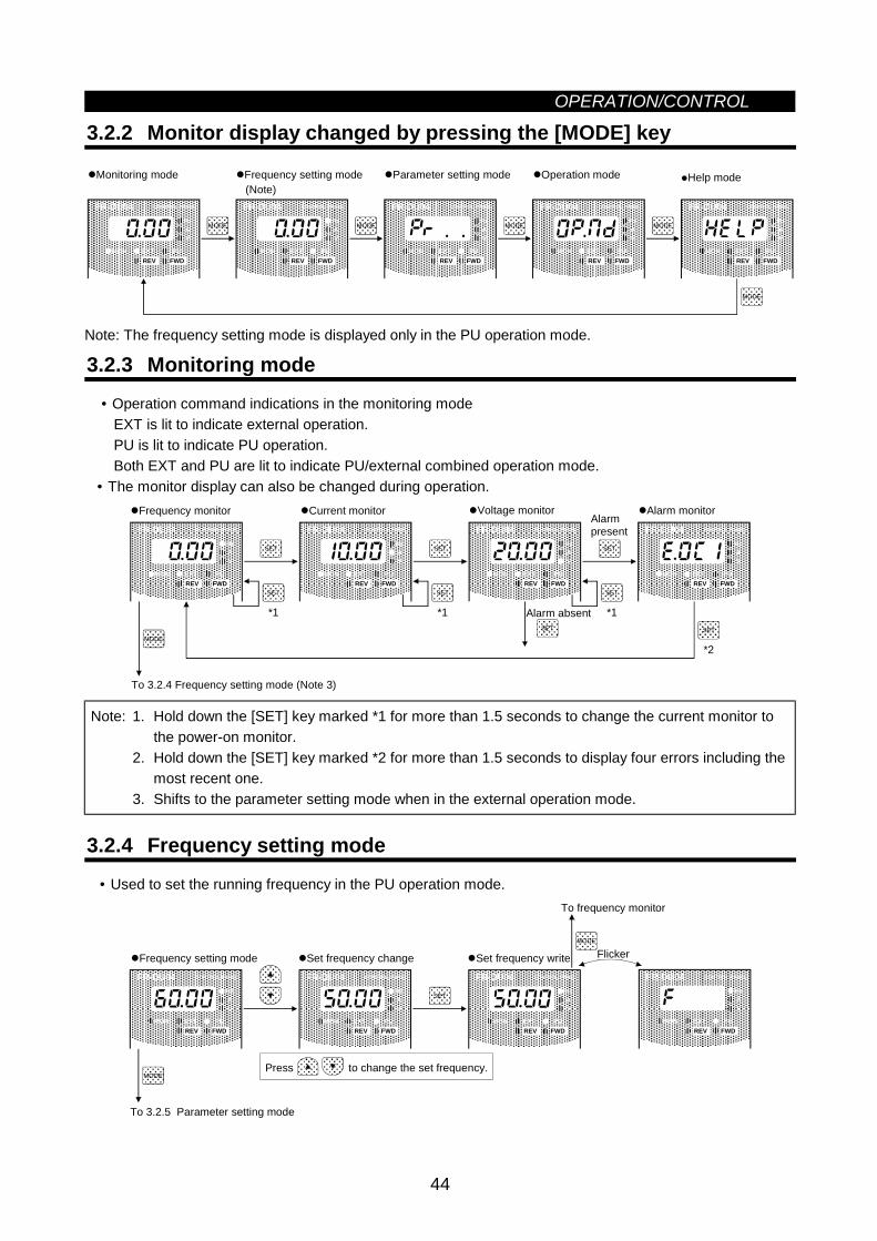
OPERATION/CONTROL
44
3.2.2 Monitor display changed by pressing the [MODE] key
MODE
MODE
MODE
MODE
MODE
Help modeMonitoring mode Parameter setting mode Operation mode
FR-DU04 CONTROL PANEL
Hz
MON EXT PU
AV
REV FWD
Frequency setting mode (Note)
FR-DU04 CONTROL PANEL
Hz
MON EXT PU
AV
REV FWD
FR-DU04 CONTROL PANEL
Hz
MON EXT PU
AV
REV FWD
FR-DU04 CONTROL PANEL
Hz
MON EXT PU
AV
REV FWD
FR-DU04 CONTROL PANEL
Hz
MON EXT PU
AV
REV FWD
Note: The frequency setting mode is displayed only in the PU operation mode.
3.2.3 Monitoring mode• Operation command indications in the monitoring mode
EXT is lit to indicate external operation.PU is lit to indicate PU operation.Both EXT and PU are lit to indicate PU/external combined operation mode.
• The monitor display can also be changed during operation.
MODE
SET
SET
SET
SET
SET
SET
*1
SET
*1
SET
*1
*2
To 3.2.4 Frequency setting mode (Note 3)
Frequency monitor Current monitor Voltage monitor Alarm monitorAlarmpresent
Alarm absent
FR-DU04 CONTROL PANEL
Hz
MON EXT PU
AV
REV FWD
FR-DU04 CONTROL PANEL
Hz
MON EXT PU
AV
REV FWD
FR-DU04 CONTROL PANEL
Hz
MON EXT PU
AV
REV FWD
FR-DU04 CONTROL PANEL
Hz
MON EXT PU
AV
REV FWD
Note: 1. Hold down the [SET] key marked *1 for more than 1.5 seconds to change the current monitor tothe power-on monitor.
2. Hold down the [SET] key marked *2 for more than 1.5 seconds to display four errors including themost recent one.
3. Shifts to the parameter setting mode when in the external operation mode.
3.2.4 Frequency setting mode• Used to set the running frequency in the PU operation mode.
Press to change the set frequency.MODE
SET
MODE
To 3.2.5 Parameter setting mode
Set frequency writeSet frequency change
To frequency monitor
FR-DU04 CONTROL PANEL
Hz
MON EXT PU
AV
REV FWD
FR-DU04 CONTROL PANEL
Hz
MON EXT PU
AV
REV FWD
FR-DU04 CONTROL PANEL
Hz
MON EXT PU
AV
REV FWD
Flicker
FR-DU04 CONTROL PANEL
Hz
MON EXT PU
AV
REV FWD
Frequency setting mode
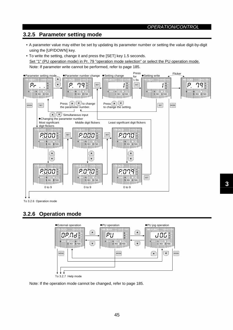
OPERATION/CONTROL
45
3.2.5 Parameter setting mode• A parameter value may either be set by updating its parameter number or setting the value digit-by-digit using the [UP/DOWN] key.• To write the setting, change it and press the [SET] key 1.5 seconds. Set "1" (PU operation mode) in Pr. 79 "operation mode selection" or select the PU operation mode. Note: If parameter write cannot be performed, refer to page 185.
MODE
SET
SET
SET
SET
SET
MODE
SET
0 to 9
SET
To 3.2.6 Operation mode
Parameter number change Setting changePressfor1.5s
Setting writeFlicker
Press
to change the setting.
Simultaneous input
Most significantdigit flickers
Middle digit flickers Least significant digit flickersChanging the parameter number
to changePress
FR-DU04 CONTROL PANEL
Hz
MON EXT PU
AV
REV FWD
FR-DU04 CONTROL PANEL
Hz
MON EXT PU
AV
REV FWD
FR-DU04 CONTROL PANEL
Hz
MON EXT PU
AV
REV FWD
FR-DU04 CONTROL PANEL
Hz
MON EXT PU
AV
REV FWD
FR-DU04 CONTROL PANEL
Hz
MON EXT PU
AV
REV FWD
FR-DU04 CONTROL PANEL
Hz
MON EXT PU
AV
REV FWD
FR-DU04 CONTROL PANEL
Hz
MON EXT PU
AV
REV FWD
FR-DU04 CONTROL PANEL
Hz
MON EXT PU
AV
REV FWD
FR-DU04 CONTROL PANEL
Hz
MON EXT PU
AV
REV FWD
FR-DU04 CONTROL PANEL
Hz
MON EXT PU
AV
REV FWD
FR-DU04 CONTROL PANEL
Hz
MON EXT PU
AV
REV FWD
0 to 9 0 to 9
the parameter number.
Parameter setting mode
3.2.6 Operation mode
MODE
MODE
MODE
To 3.2.7 Help mode
External operation PU operation PU jog operation
FR-DU04 CONTROL PANEL
Hz
MON EXT PU
AV
REV FWD
FR-DU04 CONTROL PANEL
Hz
MON EXT PU
AV
REV FWD
FR-DU04 CONTROL PANEL
Hz
MON EXT PU
AV
REV FWD
Note: If the operation mode cannot be changed, refer to page 185.
3
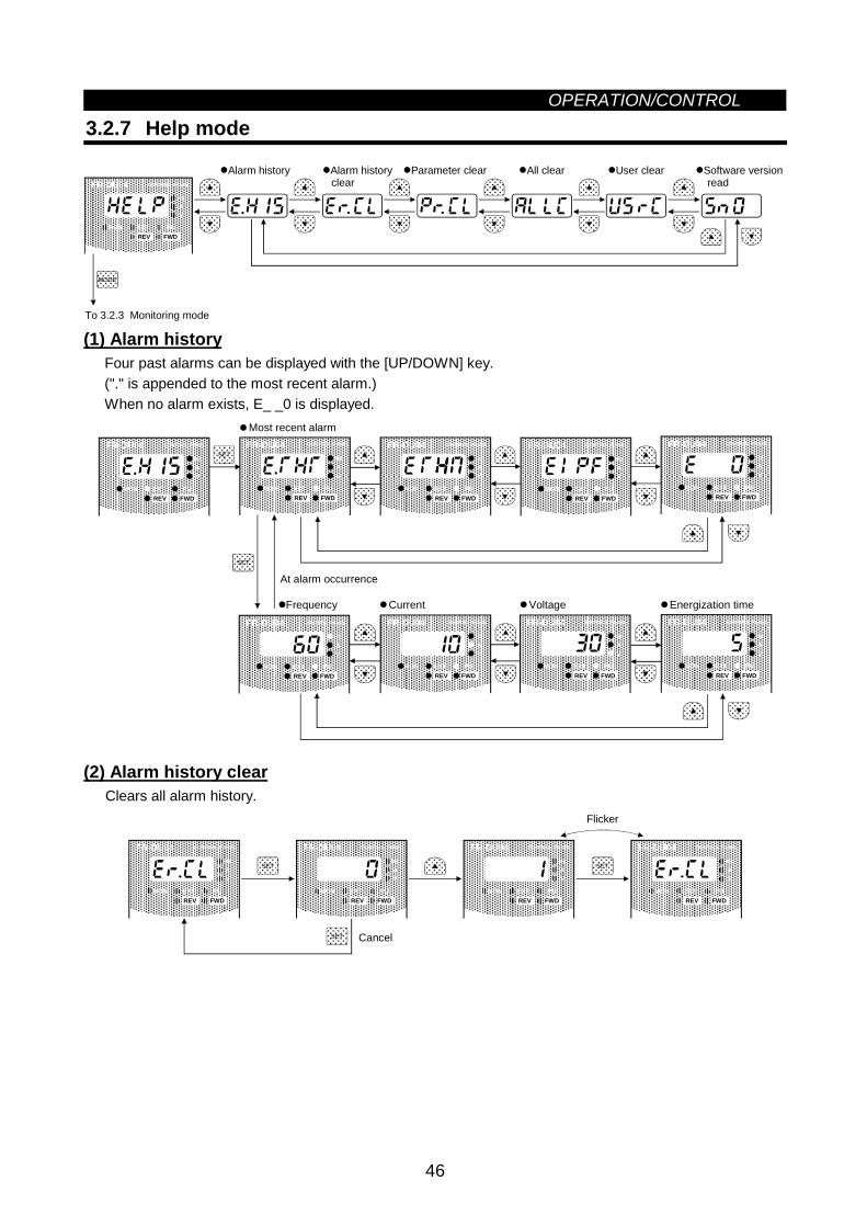
OPERATION/CONTROL
46
3.2.7 Help mode
MODE
To 3.2.3 Monitoring mode
Alarm history Alarm history clear
Parameter clear All clear User clear Software version read
FR-DU04 CONTROL PANEL
Hz
MON EXT PU
AV
REV FWD
(1) Alarm historyFour past alarms can be displayed with the [UP/DOWN] key.("." is appended to the most recent alarm.)When no alarm exists, E_ _0 is displayed.
FR-DU04 CONTROL PANEL
Hz
MON EXT PU
AV
REV FWD
FR-DU04 CONTROL PANEL
Hz
MON EXT PU
AV
REV FWD
SET
FR-DU04 CONTROL PANEL
Hz
MON EXT PU
AV
REV FWD
FR-DU04 CONTROL PANEL
Hz
MON EXT PU
AV
REV FWD
FR-DU04 CONTROL PANEL
Hz
MON EXT PU
AV
REV FWD
Most recent alarm
FR-DU04 CONTROL PANEL
Hz
MON EXT PU
AV
REV FWD
FR-DU04 CONTROL PANEL
Hz
MON EXT PU
AV
REV FWD
FR-DU04 CONTROL PANEL
Hz
MON EXT PU
AV
REV FWD
FR-DU04 CONTROL PANEL
Hz
MON EXT PU
AV
REV FWD
Frequency Current Voltage Energization time
SET
At alarm occurrence
(2) Alarm history clearClears all alarm history.
SET
SET
SET
Flicker
Cancel
FR-DU04 CONTROL PANEL
Hz
MON EXT PU
AV
REV FWD
FR-DU04 CONTROL PANEL
Hz
MON EXT PU
AV
REV FWD
FR-DU04 CONTROL PANEL
Hz
MON EXT PU
AV
REV FWD
FR-DU04 CONTROL PANEL
Hz
MON EXT PU
AV
REV FWD
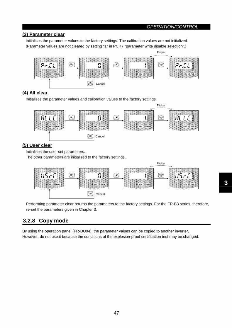
OPERATION/CONTROL
47
(3) Parameter clearInitialises the parameter values to the factory settings. The calibration values are not initialized.(Parameter values are not cleared by setting "1" in Pr. 77 "parameter write disable selection".)
SET
SET
SET
Flicker
Cancel
FR-DU04 CONTROL PANEL
Hz
MON EXT PU
AV
REV FWD
FR-DU04 CONTROL PANEL
Hz
MON EXT PU
AV
REV FWD
FR-DU04 CONTROL PANEL
Hz
MON EXT PU
AV
REV FWD
FR-DU04 CONTROL PANEL
Hz
MON EXT PU
AV
REV FWD
(4) All clearInitialises the parameter values and calibration values to the factory settings.
SET
SET
SET
Flicker
Cancel
FR-DU04 CONTROL PANEL
Hz
MON EXT PU
AV
REV FWD
FR-DU04 CONTROL PANEL
Hz
MON EXT PU
AV
REV FWD
FR-DU04 CONTROL PANEL
Hz
MON EXT PU
AV
REV FWD
FR-DU04 CONTROL PANEL
Hz
MON EXT PU
AV
REV FWD
(5) User clearInitialises the user-set parameters.The other parameters are initialized to the factory settings.
SET
SET
SET
Flicker
Cancel
FR-DU04 CONTROL PANEL
Hz
MON EXT PU
AV
REV FWD
FR-DU04 CONTROL PANEL
Hz
MON EXT PU
AV
REV FWD
FR-DU04 CONTROL PANEL
Hz
MON EXT PU
AV
REV FWD
FR-DU04 CONTROL PANEL
Hz
MON EXT PU
AV
REV FWD
Performing parameter clear returns the parameters to the factory settings. For the FR-B3 series, therefore,re-set the parameters given in Chapter 3.
3.2.8 Copy mode
By using the operation panel (FR-DU04), the parameter values can be copied to another inverter.However, do not use it because the conditions of the explosion-proof certification test may be changed.
3
3.3 OperationOPERATION/CONTROL
48
3.3 Operation
3.3.1 Pre-operation checksBefore starting operation, check the following:
• SafetyPerform test operation after making sure that safety is ensured if the machine should become out ofcontrol.
• MachineMake sure that the machine is free of damage.
• ParametersSet the parameter values to match the operating machine system environment.
• Test operationPerform test operation and make sure that the machine operates safely under light load at a low frequency.After that, start operation.Run the FR-B3 series under advanced magnetic flux vector control.
• Motor checkCheck that the motor is the Mitsubishi pressure-resistant, explosion-proof motor.The FR-B-750 to 45K (200V class) and FR-B-750 to 55K (400V class) should be used with the motor typeof X(E)F-(N)E.The FR-B3-(H)400 to 37K should be used with the motor type of X(E)F-(N)ECA-2.The FR-B3-N(H)400 to 37K should be used with the motor type of X(E)F-(N)ECA-1.
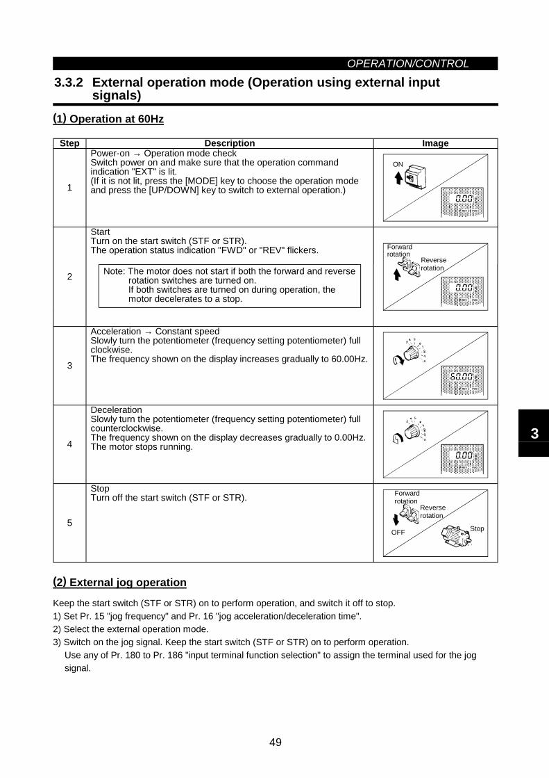
OPERATION/CONTROL
49
3.3.2 External operation mode (Operation using external inputsignals)
(1) Operation at 60Hz
Step Description Image
1
Power-on → Operation mode checkSwitch power on and make sure that the operation commandindication "EXT" is lit.(If it is not lit, press the [MODE] key to choose the operation modeand press the [UP/DOWN] key to switch to external operation.)
ON
FR-DU04 CONTROL PANEL
Hz
MON EXT PU
AV
REV FWD
StartTurn on the start switch (STF or STR).The operation status indication "FWD" or "REV" flickers.
Note: The motor does not start if both the forward and reverserotation switches are turned on.If both switches are turned on during operation, themotor decelerates to a stop.
2
Reverserotation
Forwardrotation
FR-DU04 CONTROL PANEL
Hz
MON EXT PU
AV
REV FWD
3
Acceleration → Constant speedSlowly turn the potentiometer (frequency setting potentiometer) fullclockwise.The frequency shown on the display increases gradually to 60.00Hz.
FR-DU04 CONTROL PANEL
Hz
MON EXT PU
AV
REV FWD
4
DecelerationSlowly turn the potentiometer (frequency setting potentiometer) fullcounterclockwise.The frequency shown on the display decreases gradually to 0.00Hz.The motor stops running.
FR-DU04 CONTROL PANEL
Hz
MON EXT PU
AV
REV FWD
5
StopTurn off the start switch (STF or STR).
OFF Stop
Forwardrotation
Reverserotation
(2) External jog operation
Keep the start switch (STF or STR) on to perform operation, and switch it off to stop.1) Set Pr. 15 "jog frequency" and Pr. 16 "jog acceleration/deceleration time".2) Select the external operation mode.3) Switch on the jog signal. Keep the start switch (STF or STR) on to perform operation.
Use any of Pr. 180 to Pr. 186 "input terminal function selection" to assign the terminal used for the jogsignal.
3
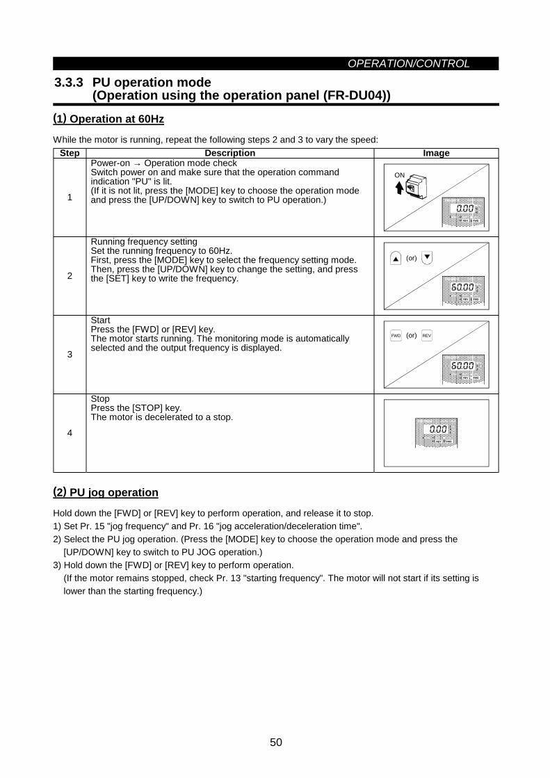
OPERATION/CONTROL
50
3.3.3 PU operation mode(Operation using the operation panel (FR-DU04))
(1) Operation at 60Hz
While the motor is running, repeat the following steps 2 and 3 to vary the speed:Step Description Image
1
Power-on → Operation mode checkSwitch power on and make sure that the operation commandindication "PU" is lit.(If it is not lit, press the [MODE] key to choose the operation modeand press the [UP/DOWN] key to switch to PU operation.)
ON
FR-DU04 CONTROL PANEL
Hz
MON EXT PU
AV
REV FWD
2
Running frequency settingSet the running frequency to 60Hz.First, press the [MODE] key to select the frequency setting mode.Then, press the [UP/DOWN] key to change the setting, and pressthe [SET] key to write the frequency.
(or)
FR-DU04 CONTROL PANEL
Hz
MON EXT PU
AV
REV FWD
3
StartPress the [FWD] or [REV] key.The motor starts running. The monitoring mode is automaticallyselected and the output frequency is displayed.
REVFWD (or)
FR-DU04 CONTROL PANEL
Hz
MON EXT PU
AV
REV FWD
4
StopPress the [STOP] key.The motor is decelerated to a stop.
FR-DU04 CONTROL PANEL
Hz
MON EXT PU
AV
REV FWD
(2) PU jog operation
Hold down the [FWD] or [REV] key to perform operation, and release it to stop.1) Set Pr. 15 "jog frequency" and Pr. 16 "jog acceleration/deceleration time".2) Select the PU jog operation. (Press the [MODE] key to choose the operation mode and press the
[UP/DOWN] key to switch to PU JOG operation.)3) Hold down the [FWD] or [REV] key to perform operation.
(If the motor remains stopped, check Pr. 13 "starting frequency". The motor will not start if its setting islower than the starting frequency.)
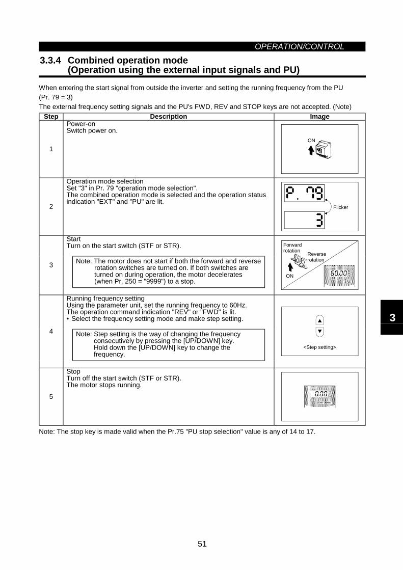
OPERATION/CONTROL
51
3.3.4 Combined operation mode(Operation using the external input signals and PU)
When entering the start signal from outside the inverter and setting the running frequency from the PU(Pr. 79 = 3)The external frequency setting signals and the PU's FWD, REV and STOP keys are not accepted. (Note)
Step Description Image
1
Power-onSwitch power on.
ON
2
Operation mode selectionSet "3" in Pr. 79 "operation mode selection".The combined operation mode is selected and the operation statusindication "EXT" and "PU" are lit.
Flicker
StartTurn on the start switch (STF or STR).
Note: The motor does not start if both the forward and reverserotation switches are turned on. If both switches areturned on during operation, the motor decelerates(when Pr. 250 = "9999") to a stop.
3ON
Reverserotation
Forwardrotation
FR-DU04 CONTROL PANEL
Hz
MON EXT PU
AV
REV FWD
Running frequency settingUsing the parameter unit, set the running frequency to 60Hz.The operation command indication "REV" or "FWD" is lit.• Select the frequency setting mode and make step setting.
Note: Step setting is the way of changing the frequencyconsecutively by pressing the [UP/DOWN] key.Hold down the [UP/DOWN] key to change thefrequency.
4
<Step setting>
5
StopTurn off the start switch (STF or STR).The motor stops running.
FR-DU04 CONTROL PANEL
Hz
MON EXT PU
AV
REV FWD
Note: The stop key is made valid when the Pr.75 "PU stop selection" value is any of 14 to 17.
3

MEMO
4
CHAPTER 4PARAMETERS
This chapter explains the "parameters" of this product.The inverter is designed to perform simple variable-speedoperation with the factory settings of the parameters. Setthe necessary parameters according to the load andoperation specifications.Always read the instructions before using the equipment.
4.1 Parameter List .........................................................52 4.2 Parameter Function Details......................................63
Note: By making parameter settings, you can change the functions of contact inputterminals RL, RM, RH, RT, AU, JOG, CS and open collector output terminalsRUN, SU, IPF, OL, FU. Therefore, signal names corresponding to the functionsare used in the description of this chapter (except in the wiring examples). Notethat they are not terminal names.
Chapter 1
Chapter 2
Chapter 3
Chapter 4
Chapter 5
Chapter 6
Chapter 7
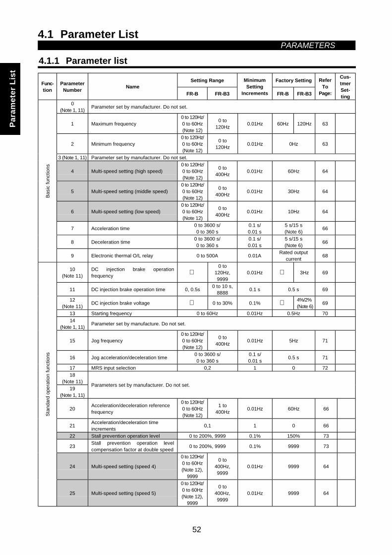
4.1 Parameter List PARAMETERS
52
4 PARAMETERS4.1 Parameter List
4.1.1 Parameter list
Setting Range Factory SettingFunc-tion
ParameterNumber Name
FR-B FR-B3
MinimumSetting
Increments FR-B FR-B3
ReferTo
Page:
Cus-tmerSet-ting
0(Note 1, 11) Parameter set by manufacturer. Do not set.
1 Maximum frequency0 to 120Hz/0 to 60Hz(Note 12)
0 to120Hz 0.01Hz 60Hz 120Hz 63
2 Minimum frequency0 to 120Hz/0 to 60Hz(Note 12)
0 to120Hz 0.01Hz 0Hz 63
3 (Note 1, 11) Parameter set by manufacturer. Do not set.
4 Multi-speed setting (high speed)0 to 120Hz/0 to 60Hz(Note 12)
0 to400Hz 0.01Hz 60Hz 64
5 Multi-speed setting (middle speed)0 to 120Hz/0 to 60Hz(Note 12)
0 to400Hz 0.01Hz 30Hz 64
6 Multi-speed setting (low speed)0 to 120Hz/0 to 60Hz(Note 12)
0 to400Hz 0.01Hz 10Hz 64
7 Acceleration time 0 to 3600 s/0 to 360 s
0.1 s/0.01 s
5 s/15 s(Note 6) 66
8 Deceleration time 0 to 3600 s/0 to 360 s
0.1 s/0.01 s
5 s/15 s(Note 6) 66
Basi
c fu
nctio
ns
9 Electronic thermal O/L relay 0 to 500A 0.01A Rated outputcurrent 68
10(Note 11)
DC injection brake operationfrequency
0 to120Hz,9999
0.01Hz 3Hz 69
11 DC injection brake operation time 0, 0.5s 0 to 10 s,8888 0.1 s 0.5 s 69
12(Note 11) DC injection brake voltage 0 to 30% 0.1% 4%/2%
(Note 6) 69
13 Starting frequency 0 to 60Hz 0.01Hz 0.5Hz 7014
(Note 1, 11) Parameter set by manufacture. Do not set.
15 Jog frequency0 to 120Hz/0 to 60Hz(Note 12)
0 to400Hz 0.01Hz 5Hz 71
16 Jog acceleration/deceleration time 0 to 3600 s/0 to 360 s
0.1 s/0.01 s 0.5 s 71
17 MRS input selection 0,2 1 0 7218
(Note 11)19
(Note 1, 11)
Parameters set by manufacturer. Do not set.
20 Acceleration/deceleration referencefrequency
0 to 120Hz/0 to 60Hz(Note 12)
1 to400Hz 0.01Hz 60Hz 66
21 Acceleration/deceleration timeincrements 0,1 1 0 66
22 Stall prevention operation level 0 to 200%, 9999 0.1% 150% 73
23 Stall prevention operation levelcompensation factor at double speed 0 to 200%, 9999 0.1% 9999 73
24 Multi-speed setting (speed 4)
0 to 120Hz/0 to 60Hz(Note 12),
9999
0 to400Hz,9999
0.01Hz 9999 64
Stan
dard
ope
ratio
n fu
nctio
ns
25 Multi-speed setting (speed 5)
0 to 120Hz/0 to 60Hz(Note 12),
9999
0 to400Hz,9999
0.01Hz 9999 64
Para
met
er L
ist
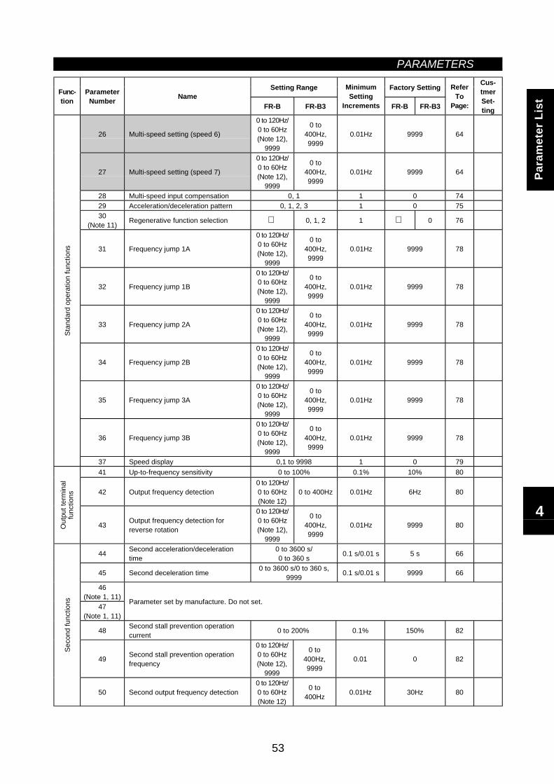
PARAMETERS
53
Setting Range Factory SettingFunc-tion
ParameterNumber Name
FR-B FR-B3
MinimumSetting
Increments FR-B FR-B3
ReferTo
Page:
Cus-tmerSet-ting
26 Multi-speed setting (speed 6)
0 to 120Hz/0 to 60Hz(Note 12),
9999
0 to400Hz,9999
0.01Hz 9999 64
27 Multi-speed setting (speed 7)
0 to 120Hz/0 to 60Hz(Note 12),
9999
0 to400Hz,9999
0.01Hz 9999 64
28 Multi-speed input compensation 0, 1 1 0 7429 Acceleration/deceleration pattern 0, 1, 2, 3 1 0 7530
(Note 11) Regenerative function selection 0, 1, 2 1 0 76
31 Frequency jump 1A
0 to 120Hz/0 to 60Hz(Note 12),
9999
0 to400Hz,9999
0.01Hz 9999 78
32 Frequency jump 1B
0 to 120Hz/0 to 60Hz(Note 12),
9999
0 to400Hz,9999
0.01Hz 9999 78
33 Frequency jump 2A
0 to 120Hz/0 to 60Hz(Note 12),
9999
0 to400Hz,9999
0.01Hz 9999 78
34 Frequency jump 2B
0 to 120Hz/0 to 60Hz(Note 12),
9999
0 to400Hz,9999
0.01Hz 9999 78
35 Frequency jump 3A
0 to 120Hz/0 to 60Hz(Note 12),
9999
0 to400Hz,9999
0.01Hz 9999 78
36 Frequency jump 3B
0 to 120Hz/0 to 60Hz(Note 12),
9999
0 to400Hz,9999
0.01Hz 9999 78
Stan
dard
ope
ratio
n fu
nctio
ns
37 Speed display 0,1 to 9998 1 0 7941 Up-to-frequency sensitivity 0 to 100% 0.1% 10% 80
42 Output frequency detection0 to 120Hz/0 to 60Hz(Note 12)
0 to 400Hz 0.01Hz 6Hz 80
Out
put t
erm
inal
func
tions
43 Output frequency detection forreverse rotation
0 to 120Hz/0 to 60Hz(Note 12),
9999
0 to400Hz,9999
0.01Hz 9999 80
44 Second acceleration/decelerationtime
0 to 3600 s/0 to 360 s 0.1 s/0.01 s 5 s 66
45 Second deceleration time 0 to 3600 s/0 to 360 s,9999 0.1 s/0.01 s 9999 66
46(Note 1, 11)
47(Note 1, 11)
Parameter set by manufacture. Do not set.
48 Second stall prevention operationcurrent 0 to 200% 0.1% 150% 82
49 Second stall prevention operationfrequency
0 to 120Hz/0 to 60Hz(Note 12),
9999
0 to400Hz,9999
0.01 0 82
Seco
nd fu
nctio
ns
50 Second output frequency detection0 to 120Hz/0 to 60Hz(Note 12)
0 to400Hz 0.01Hz 30Hz 80
Para
met
er L
ist
4
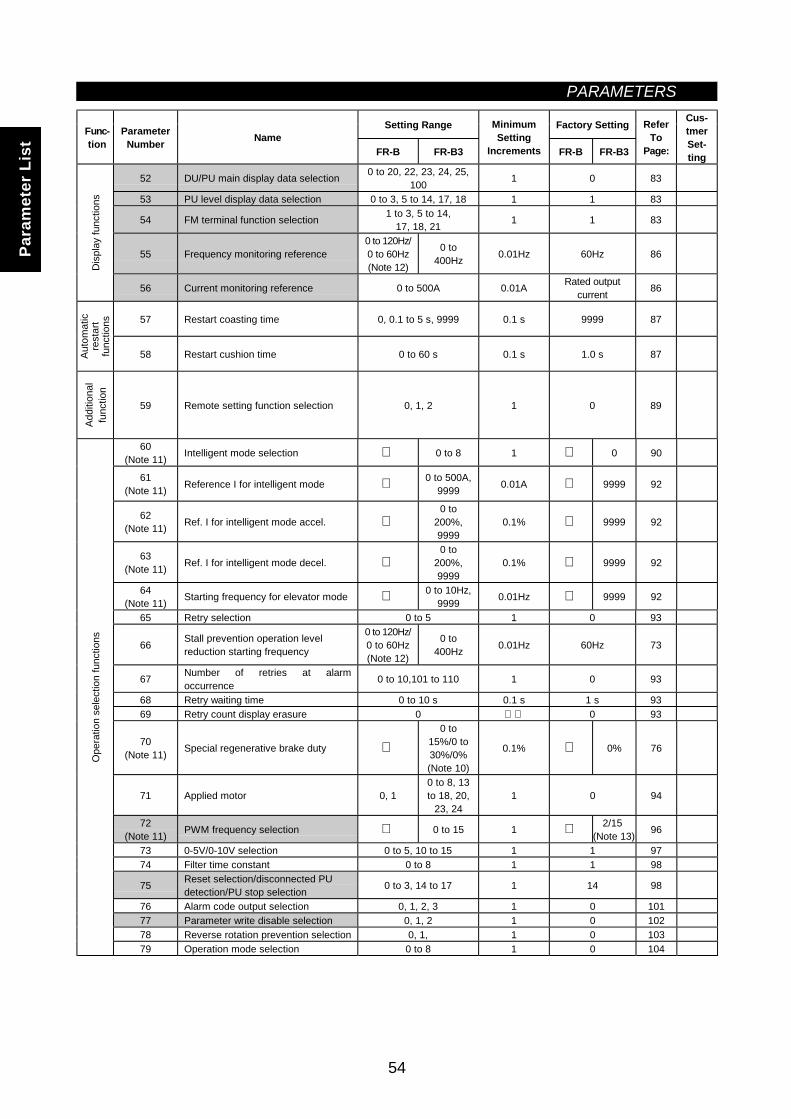
PARAMETERS
54
Setting Range Factory SettingFunc-tion
ParameterNumber Name
FR-B FR-B3
MinimumSetting
Increments FR-B FR-B3
ReferTo
Page:
Cus-tmerSet-ting
52 DU/PU main display data selection 0 to 20, 22, 23, 24, 25,100 1 0 83
53 PU level display data selection 0 to 3, 5 to 14, 17, 18 1 1 83
54 FM terminal function selection 1 to 3, 5 to 14,17, 18, 21 1 1 83
55 Frequency monitoring reference0 to 120Hz/0 to 60Hz(Note 12)
0 to400Hz 0.01Hz 60Hz 86
Dis
play
func
tions
56 Current monitoring reference 0 to 500A 0.01A Rated outputcurrent 86
57 Restart coasting time 0, 0.1 to 5 s, 9999 0.1 s 9999 87
Auto
mat
icre
star
tfu
nctio
ns
58 Restart cushion time 0 to 60 s 0.1 s 1.0 s 87
Addi
tiona
lfu
nctio
n
59 Remote setting function selection 0, 1, 2 1 0 89
60(Note 11) Intelligent mode selection 0 to 8 1 0 90
61(Note 11) Reference I for intelligent mode 0 to 500A,
9999 0.01A 9999 92
62(Note 11) Ref. I for intelligent mode accel.
0 to200%,9999
0.1% 9999 92
63(Note 11) Ref. I for intelligent mode decel.
0 to200%,9999
0.1% 9999 92
64(Note 11) Starting frequency for elevator mode 0 to 10Hz,
9999 0.01Hz 9999 92
65 Retry selection 0 to 5 1 0 93
66 Stall prevention operation levelreduction starting frequency
0 to 120Hz/0 to 60Hz(Note 12)
0 to400Hz 0.01Hz 60Hz 73
67 Number of retries at alarmoccurrence 0 to 10,101 to 110 1 0 93
68 Retry waiting time 0 to 10 s 0.1 s 1 s 9369 Retry count display erasure 0 0 93
70(Note 11) Special regenerative brake duty
0 to15%/0 to30%/0%(Note 10)
0.1% 0% 76
71 Applied motor 0, 10 to 8, 13to 18, 20,
23, 241 0 94
72(Note 11) PWM frequency selection 0 to 15 1 2/15
(Note 13) 96
73 0-5V/0-10V selection 0 to 5, 10 to 15 1 1 9774 Filter time constant 0 to 8 1 1 98
75 Reset selection/disconnected PUdetection/PU stop selection 0 to 3, 14 to 17 1 14 98
76 Alarm code output selection 0, 1, 2, 3 1 0 10177 Parameter write disable selection 0, 1, 2 1 0 10278 Reverse rotation prevention selection 0, 1, 1 0 103
Ope
ratio
n se
lect
ion
func
tions
79 Operation mode selection 0 to 8 1 0 104
Para
met
er L
ist
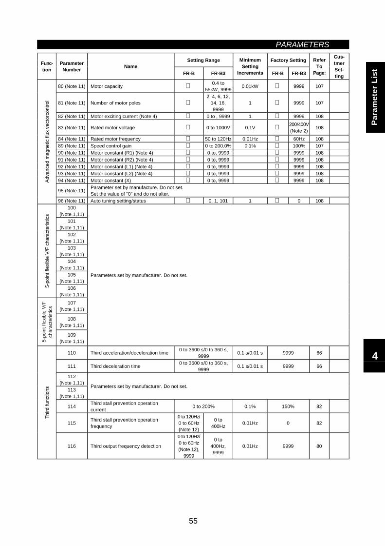
PARAMETERS
55
Setting Range Factory SettingFunc-tion
ParameterNumber Name
FR-B FR-B3
MinimumSetting
Increments FR-B FR-B3
ReferTo
Page:
Cus-tmerSet-ting
80 (Note 11) Motor capacity 0.4 to55kW, 9999 0.01kW 9999 107
81 (Note 11) Number of motor poles 2, 4, 6, 12,
14, 16,9999
1 9999 107
82 (Note 11) Motor exciting current (Note 4) 0 to , 9999 1 9999 108
83 (Note 11) Rated motor voltage 0 to 1000V 0.1V 200/400V(Note 2) 108
84 (Note 11) Rated motor frequency 50 to 120Hz 0.01Hz 60Hz 10889 (Note 11) Speed control gain 0 to 200.0% 0.1% 100% 10790 (Note 11) Motor constant (R1) (Note 4) 0 to, 9999 9999 10891 (Note 11) Motor constant (R2) (Note 4) 0 to, 9999 9999 10892 (Note 11) Motor constant (L1) (Note 4) 0 to, 9999 9999 10893 (Note 11) Motor constant (L2) (Note 4) 0 to, 9999 9999 10894 (Note 11) Motor constant (X) 0 to, 9999 9999 108
95 (Note 11) Parameter set by manufacture. Do not set.Set the value of "0" and do not alter.
Adva
nced
mag
netic
flux
vec
torc
ontro
l
96 (Note 11) Auto tuning setting/status 0, 1, 101 1 0 108100
(Note 1,11)101
(Note 1,11)102
(Note 1,11)103
(Note 1,11)104
(Note 1,11)105
(Note 1,11)
5-po
int f
lexi
ble
V/F
char
acte
ristic
s
106(Note 1,11)
107(Note 1,11)
108(Note 1,11)
5-po
int f
lexi
ble
V/F
char
acte
ristic
s
109(Note 1,11)
Parameters set by manufacturer. Do not set.
110 Third acceleration/deceleration time 0 to 3600 s/0 to 360 s,9999 0.1 s/0.01 s 9999 66
111 Third deceleration time 0 to 3600 s/0 to 360 s,9999 0.1 s/0.01 s 9999 66
112(Note 1,11)
113(Note 1,11)
Parameters set by manufacturer. Do not set.
114 Third stall prevention operationcurrent 0 to 200% 0.1% 150% 82
115 Third stall prevention operationfrequency
0 to 120Hz/0 to 60Hz(Note 12)
0 to400Hz 0.01Hz 0 82
Third
func
tions
116 Third output frequency detection
0 to 120Hz/0 to 60Hz(Note 12),
9999
0 to400Hz,9999
0.01Hz 9999 80
4Pa
ram
eter
Lis
t
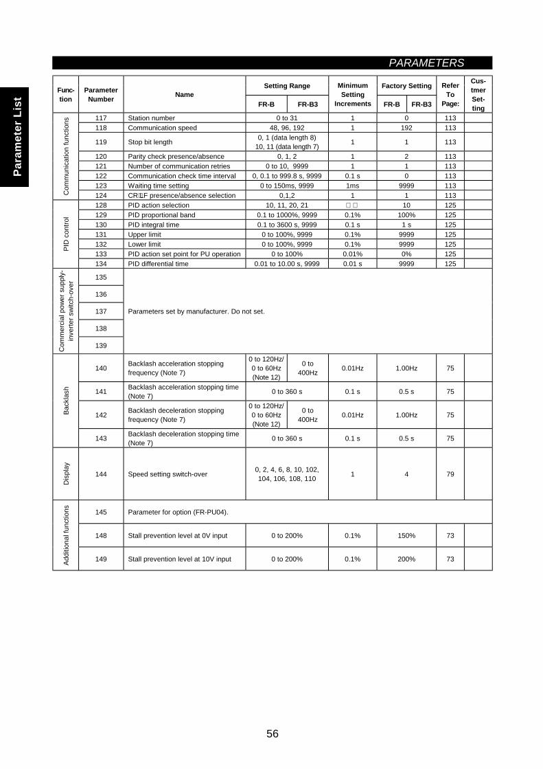
PARAMETERS
56
Setting Range Factory SettingFunc-tion
ParameterNumber Name
FR-B FR-B3
MinimumSetting
Increments FR-B FR-B3
ReferTo
Page:
Cus-tmerSet-ting
117 Station number 0 to 31 1 0 113118 Communication speed 48, 96, 192 1 192 113
119 Stop bit length 0, 1 (data length 8)10, 11 (data length 7) 1 1 113
120 Parity check presence/absence 0, 1, 2 1 2 113121 Number of communication retries 0 to 10, 9999 1 1 113122 Communication check time interval 0, 0.1 to 999.8 s, 9999 0.1 s 0 113123 Waiting time setting 0 to 150ms, 9999 1ms 9999 113
Com
mun
icat
ion
func
tions
124 CR⋅LF presence/absence selection 0,1,2 1 1 113128 PID action selection 10, 11, 20, 21 10 125129 PID proportional band 0.1 to 1000%, 9999 0.1% 100% 125130 PID integral time 0.1 to 3600 s, 9999 0.1 s 1 s 125131 Upper limit 0 to 100%, 9999 0.1% 9999 125132 Lower limit 0 to 100%, 9999 0.1% 9999 125133 PID action set point for PU operation 0 to 100% 0.01% 0% 125
PID
con
trol
134 PID differential time 0.01 to 10.00 s, 9999 0.01 s 9999 125
135
136
137
138
Com
mer
cial
pow
er s
uppl
y-in
verte
r sw
itch-
over
139
Parameters set by manufacturer. Do not set.
140 Backlash acceleration stoppingfrequency (Note 7)
0 to 120Hz/0 to 60Hz(Note 12)
0 to400Hz 0.01Hz 1.00Hz 75
141 Backlash acceleration stopping time(Note 7) 0 to 360 s 0.1 s 0.5 s 75
142 Backlash deceleration stoppingfrequency (Note 7)
0 to 120Hz/0 to 60Hz(Note 12)
0 to400Hz 0.01Hz 1.00Hz 75Ba
ckla
sh
143 Backlash deceleration stopping time(Note 7) 0 to 360 s 0.1 s 0.5 s 75
Dis
play
144 Speed setting switch-over 0, 2, 4, 6, 8, 10, 102,104, 106, 108, 110 1 4 79
145 Parameter for option (FR-PU04).
148 Stall prevention level at 0V input 0 to 200% 0.1% 150% 73
Addi
tiona
l fun
ctio
ns
149 Stall prevention level at 10V input 0 to 200% 0.1% 200% 73
Para
met
er L
ist
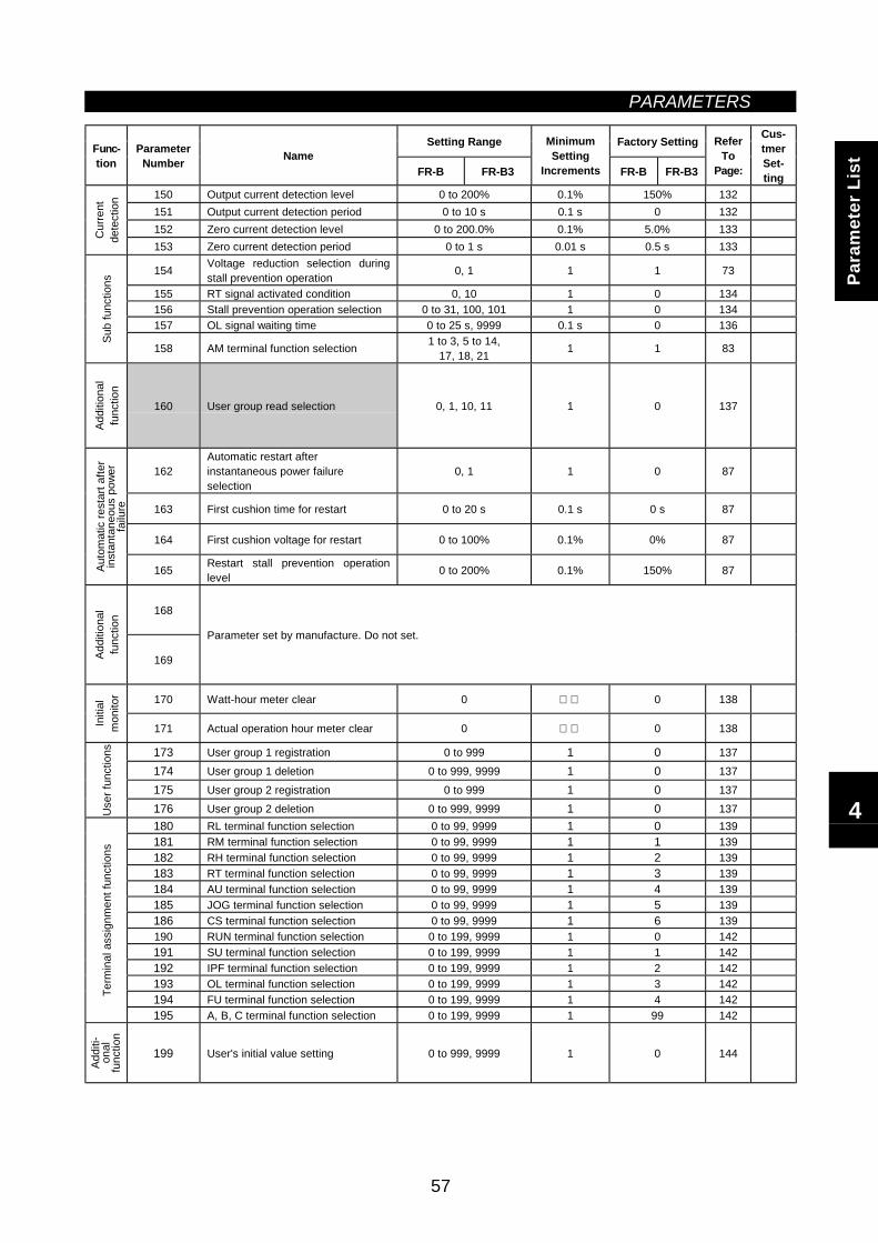
PARAMETERS
57
Setting Range Factory SettingFunc-tion
ParameterNumber Name
FR-B FR-B3
MinimumSetting
Increments FR-B FR-B3
ReferTo
Page:
Cus-tmerSet-ting
150 Output current detection level 0 to 200% 0.1% 150% 132151 Output current detection period 0 to 10 s 0.1 s 0 132152 Zero current detection level 0 to 200.0% 0.1% 5.0% 133C
urre
ntde
tect
ion
153 Zero current detection period 0 to 1 s 0.01 s 0.5 s 133
154 Voltage reduction selection duringstall prevention operation 0, 1 1 1 73
155 RT signal activated condition 0, 10 1 0 134156 Stall prevention operation selection 0 to 31, 100, 101 1 0 134157 OL signal waiting time 0 to 25 s, 9999 0.1 s 0 136
Sub
func
tions
158 AM terminal function selection 1 to 3, 5 to 14,17, 18, 21 1 1 83
Addi
tiona
lfu
nctio
n
160 User group read selection 0, 1, 10, 11 1 0 137
162Automatic restart afterinstantaneous power failureselection
0, 1 1 0 87
163 First cushion time for restart 0 to 20 s 0.1 s 0 s 87
164 First cushion voltage for restart 0 to 100% 0.1% 0% 87
Auto
mat
ic re
star
t afte
rin
stan
tane
ous
pow
erfa
ilure
165 Restart stall prevention operationlevel 0 to 200% 0.1% 150% 87
168
Addi
tiona
lfu
nctio
n
169
Parameter set by manufacture. Do not set.
170 Watt-hour meter clear 0 0 138
Initi
alm
onito
r
171 Actual operation hour meter clear 0 0 138
173 User group 1 registration 0 to 999 1 0 137174 User group 1 deletion 0 to 999, 9999 1 0 137175 User group 2 registration 0 to 999 1 0 137
Use
r fun
ctio
ns
176 User group 2 deletion 0 to 999, 9999 1 0 137180 RL terminal function selection 0 to 99, 9999 1 0 139181 RM terminal function selection 0 to 99, 9999 1 1 139182 RH terminal function selection 0 to 99, 9999 1 2 139183 RT terminal function selection 0 to 99, 9999 1 3 139184 AU terminal function selection 0 to 99, 9999 1 4 139185 JOG terminal function selection 0 to 99, 9999 1 5 139186 CS terminal function selection 0 to 99, 9999 1 6 139190 RUN terminal function selection 0 to 199, 9999 1 0 142191 SU terminal function selection 0 to 199, 9999 1 1 142192 IPF terminal function selection 0 to 199, 9999 1 2 142193 OL terminal function selection 0 to 199, 9999 1 3 142194 FU terminal function selection 0 to 199, 9999 1 4 142Te
rmin
al a
ssig
nmen
t fun
ctio
ns
195 A, B, C terminal function selection 0 to 199, 9999 1 99 142
Addi
ti-on
alfu
nctio
n
199 User's initial value setting 0 to 999, 9999 1 0 144
Para
met
er L
ist
4
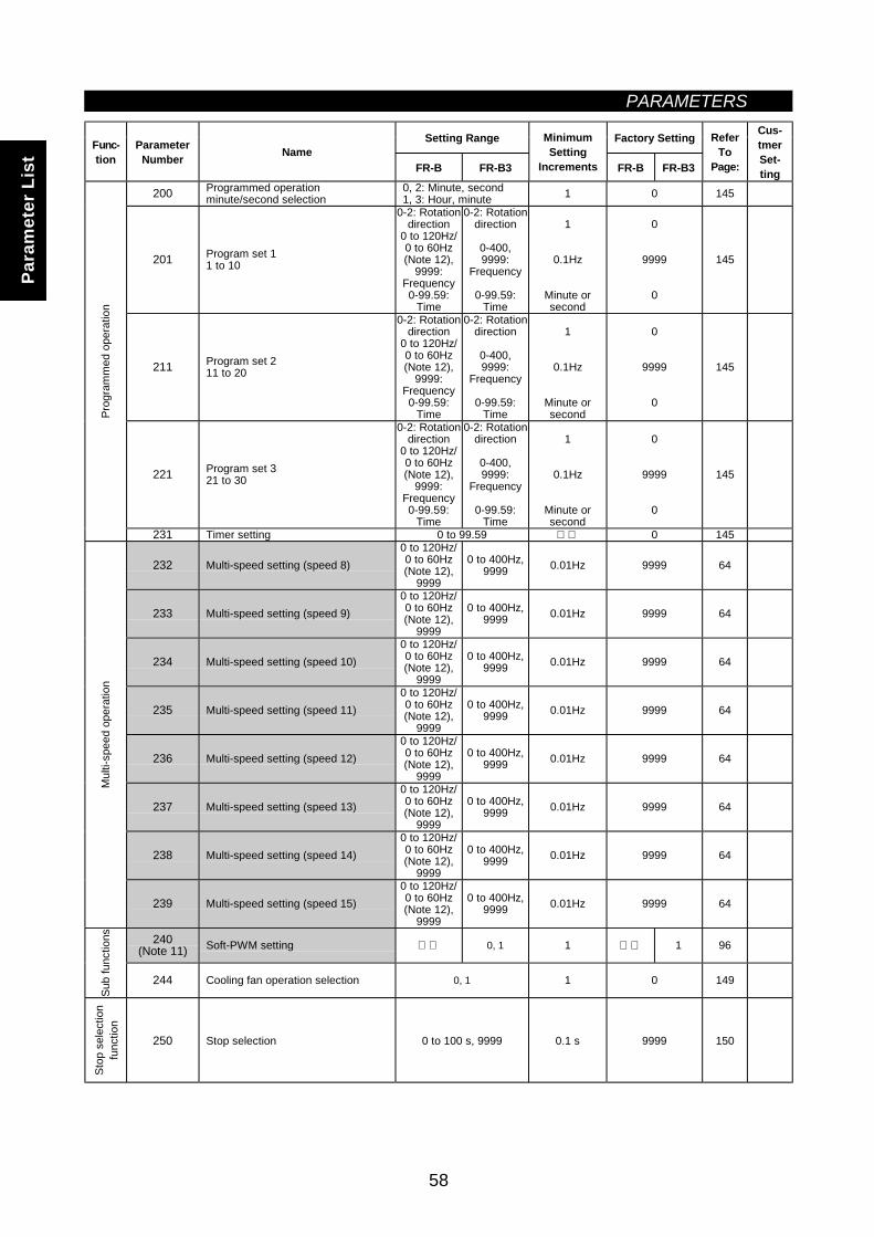
PARAMETERS
58
Setting Range Factory SettingFunc-tion
ParameterNumber Name
FR-B FR-B3
MinimumSetting
Increments FR-B FR-B3
ReferTo
Page:
Cus-tmerSet-ting
200 Programmed operationminute/second selection
0, 2: Minute, second1, 3: Hour, minute 1 0 145
201 Program set 11 to 10
0-2: Rotationdirection
0 to 120Hz/0 to 60Hz(Note 12),
9999:Frequency0-99.59:
Time
0-2: Rotationdirection
0-400,9999:
Frequency
0-99.59:Time
1
0.1Hz
Minute orsecond
0
9999
0
145
211 Program set 211 to 20
0-2: Rotationdirection
0 to 120Hz/0 to 60Hz(Note 12),
9999:Frequency0-99.59:
Time
0-2: Rotationdirection
0-400,9999:
Frequency
0-99.59:Time
1
0.1Hz
Minute orsecond
0
9999
0
145
221 Program set 321 to 30
0-2: Rotationdirection
0 to 120Hz/0 to 60Hz(Note 12),
9999:Frequency0-99.59:
Time
0-2: Rotationdirection
0-400,9999:
Frequency
0-99.59:Time
1
0.1Hz
Minute orsecond
0
9999
0
145
Prog
ram
med
ope
ratio
n
231 Timer setting 0 to 99.59 0 145
232 Multi-speed setting (speed 8)0 to 120Hz/0 to 60Hz(Note 12),
9999
0 to 400Hz,9999 0.01Hz 9999 64
233 Multi-speed setting (speed 9)0 to 120Hz/0 to 60Hz(Note 12),
9999
0 to 400Hz,9999 0.01Hz 9999 64
234 Multi-speed setting (speed 10)0 to 120Hz/0 to 60Hz(Note 12),
9999
0 to 400Hz,9999 0.01Hz 9999 64
235 Multi-speed setting (speed 11)0 to 120Hz/0 to 60Hz(Note 12),
9999
0 to 400Hz,9999 0.01Hz 9999 64
236 Multi-speed setting (speed 12)0 to 120Hz/0 to 60Hz(Note 12),
9999
0 to 400Hz,9999 0.01Hz 9999 64
237 Multi-speed setting (speed 13)0 to 120Hz/0 to 60Hz(Note 12),
9999
0 to 400Hz,9999 0.01Hz 9999 64
238 Multi-speed setting (speed 14)0 to 120Hz/0 to 60Hz(Note 12),
9999
0 to 400Hz,9999 0.01Hz 9999 64
Mul
ti-sp
eed
oper
atio
n
239 Multi-speed setting (speed 15)0 to 120Hz/0 to 60Hz(Note 12),
9999
0 to 400Hz,9999 0.01Hz 9999 64
240(Note 11) Soft-PWM setting 0, 1 1 1 96
Sub
func
tions
244 Cooling fan operation selection 0, 1 1 0 149
Stop
sel
ectio
nfu
nctio
n
250 Stop selection 0 to 100 s, 9999 0.1 s 9999 150
Para
met
er L
ist
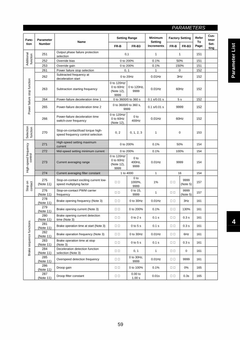
PARAMETERS
59
Setting Range Factory SettingFunc-tion
ParameterNumber Name
FR-B FR-B3
MinimumSetting
Increments FR-B FR-B3
ReferTo
Page:
Cus-tmerSet-ting
251 Output phase failure protectionselection 0,1 1 1 151
252 Override bias 0 to 200% 0.1% 50% 151
Addi
tiona
lfu
nctio
n
253 Override gain 0 to 200% 0.1% 150% 151261 Power failure stop selection 0, 1 1 0 152
262 Subtracted frequency atdeceleration start 0 to 20Hz 0.01Hz 3Hz 152
263 Subtraction starting frequency
0 to 120Hz/0 to 60Hz(Note 12),
9999
0 to 120Hz,9999 0.01Hz 60Hz 152
264 Power-failure deceleration time 1 0 to 3600/0 to 360 s 0.1 s/0.01 s 5 s 152
265 Power-failure deceleration time 2 0 to 3600/0 to 360 s,9999 0.1 s/0.01 s 9999 152
Pow
er fa
ilure
sto
p fu
nctio
n
266 Power-failure deceleration timeswitch-over frequency
0 to 120Hz/0 to 60Hz(Note 12),
0 to400Hz 0.01Hz 60Hz 152
Sele
ctio
nfu
nctio
n
270 Stop-on-contact/load torque high-speed frequency control selection 0, 2 0, 1, 2, 3 1 0 153
271 High-speed setting maximumcurrent 0 to 200% 0.1% 50% 154
272 Mid-speed setting minimum current 0 to 200% 0.1% 100% 154
273 Current averaging range
0 to 120Hz/0 to 60Hz(Note 12),
9999
0 to400Hz,9999
0.01Hz 9999 154
Hig
h-sp
eed
frequ
ency
cont
rol
274 Current averaging filter constant 1 to 4000 1 16 154
275(Note 11)
Stop-on-contact exciting current low-speed multiplying factor
0 to1000%,
99991%
9999(Note 5) 157
Stop
on
cont
act
276(Note 11)
Stop-on-contact PWM carrierfrequency
0 to 15,9999 1
9999(Note 5) 157
278(Note 11) Brake opening frequency (Note 3) 0 to 30Hz 0.01Hz 3Hz 161
279(Note 11) Brake opening current (Note 3) 0 to 200% 0.1% 130% 161
280(Note 11)
Brake opening current detectiontime (Note 3) 0 to 2 s 0.1 s 0.3 s 161
281(Note 11) Brake operation time at start (Note 3) 0 to 5 s 0.1 s 0.3 s 161
282(Note 11) Brake operation frequency (Note 3) 0 to 30Hz 0.01Hz 6Hz 161
283(Note 11)
Brake operation time at stop(Note 3) 0 to 5 s 0.1 s 0.3 s 161
284(Note 11)
Deceleration detection functionselection (Note 3) 0, 1 1 0 161
285(Note 11) Overspeed detection frequency
0 to 30Hz,9999 0.01Hz 9999 161
286(Note 11) Droop gain 0 to 100% 0.1% 0% 165
Brak
e se
quen
ce fu
nctio
ns
287(Note 11) Droop filter constant
0.00 to1.00 s 0.01s 0.3s 165
Para
met
er L
ist
4
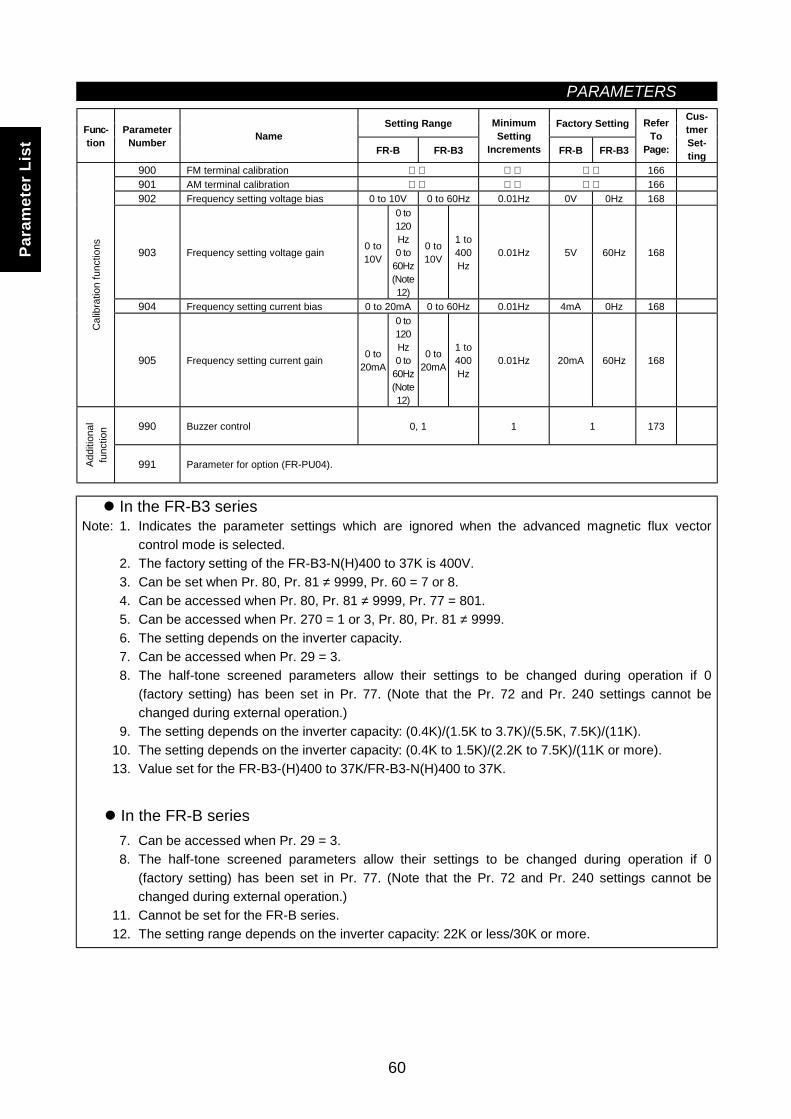
PARAMETERS
60
Setting Range Factory SettingFunc-tion
ParameterNumber Name
FR-B FR-B3
MinimumSetting
Increments FR-B FR-B3
ReferTo
Page:
Cus-tmerSet-ting
900 FM terminal calibration 166901 AM terminal calibration 166902 Frequency setting voltage bias 0 to 10V 0 to 60Hz 0.01Hz 0V 0Hz 168
903 Frequency setting voltage gain 0 to10V
0 to120Hz0 to
60Hz(Note12)
0 to10V
1 to400Hz
0.01Hz 5V 60Hz 168
904 Frequency setting current bias 0 to 20mA 0 to 60Hz 0.01Hz 4mA 0Hz 168
Cal
ibra
tion
func
tions
905 Frequency setting current gain 0 to20mA
0 to120Hz0 to
60Hz(Note12)
0 to20mA
1 to400Hz
0.01Hz 20mA 60Hz 168
990 Buzzer control 0, 1 1 1 173
Addi
tiona
lfu
nctio
n
991 Parameter for option (FR-PU04).
In the FR-B3 seriesNote: 1. Indicates the parameter settings which are ignored when the advanced magnetic flux vector
control mode is selected.2. The factory setting of the FR-B3-N(H)400 to 37K is 400V.3. Can be set when Pr. 80, Pr. 81 ≠ 9999, Pr. 60 = 7 or 8.4. Can be accessed when Pr. 80, Pr. 81 ≠ 9999, Pr. 77 = 801.5. Can be accessed when Pr. 270 = 1 or 3, Pr. 80, Pr. 81 ≠ 9999.6. The setting depends on the inverter capacity.7. Can be accessed when Pr. 29 = 3.8. The half-tone screened parameters allow their settings to be changed during operation if 0
(factory setting) has been set in Pr. 77. (Note that the Pr. 72 and Pr. 240 settings cannot bechanged during external operation.)
9. The setting depends on the inverter capacity: (0.4K)/(1.5K to 3.7K)/(5.5K, 7.5K)/(11K).10. The setting depends on the inverter capacity: (0.4K to 1.5K)/(2.2K to 7.5K)/(11K or more).13. Value set for the FR-B3-(H)400 to 37K/FR-B3-N(H)400 to 37K.
In the FR-B series7. Can be accessed when Pr. 29 = 3.8. The half-tone screened parameters allow their settings to be changed during operation if 0
(factory setting) has been set in Pr. 77. (Note that the Pr. 72 and Pr. 240 settings cannot bechanged during external operation.)
11. Cannot be set for the FR-B series.12. The setting range depends on the inverter capacity: 22K or less/30K or more.
Para
met
er L
ist
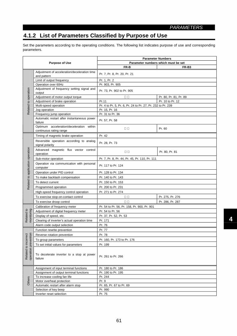
PARAMETERS
61
4.1.2 List of Parameters Classified by Purpose of UseSet the parameters according to the operating conditions. The following list indicates purpose of use and correspondingparameters.
Parameter NumbersParameter numbers which must be setPurpose of Use
FR-B FR-B3Adjustment of acceleration/deceleration timeand pattern Pr. 7, Pr. 8, Pr. 20, Pr. 21
Limit of output frequency Pr. 1, Pr. 2Operation over 60Hz Pr. 903, Pr. 905Adjustment of frequency setting signal andoutput Pr. 73, Pr. 902 to Pr. 905
Adjustment of motor output torque Pr. 80, Pr. 81, Pr. 89Adjustment of brake operation Pr.11 Pr. 10 to Pr. 12Multi-speed operation Pr. 4 to Pr. 5, Pr. 6, Pr. 24 to Pr. 27, Pr. 232 to Pr. 239Jog operation Pr. 15, Pr. 16Frequency jump operation Pr. 31 to Pr. 36Automatic restart after instantaneous powerfailure Pr. 57, Pr. 58
Rel
ated
to o
pera
tion
Optimum acceleration/deceleration withincontinuous rating range Pr. 60
Timing of magnetic brake operation Pr. 42
Reversible operation according to analogsignal polarity Pr. 28, Pr. 73
Advanced magnetic flux vector controloperation Pr. 80, Pr. 81
Sub-motor operation Pr. 7, Pr. 8, Pr. 44, Pr. 45, Pr. 110, Pr. 111Operation via communication with personalcomputer Pr. 117 to Pr. 124
Operation under PID control Pr. 128 to Pr. 134To make backlash compensation Pr. 140 to Pr. 143To detect current Pr. 150 to Pr. 153Programmed operation Pr. 200 to Pr. 231High-speed frequency control operation Pr. 271 to Pr. 274To exercise stop-on-contact control Pr. 275, Pr. 276
Rel
ated
to a
pplic
atio
n op
erat
ion
To exercise droop control Pr. 286, Pr. 287Calibration of frequency meter Pr. 54 to Pr. 56, Pr. 158, Pr. 900, Pr. 901Adjustment of digital frequency meter Pr. 54 to Pr. 56Display of speed, etc. Pr. 37, Pr. 52, Pr. 53Clearing of inverter’s actual operation time Pr. 171R
elat
ed to
mon
itorin
g
Alarm code output selection Pr. 76Function rewrite prevention Pr. 77Reverse rotation prevention Pr. 78To group parameters Pr. 160, Pr. 173 to Pr. 176To set initial values for parameters Pr. 199
Rel
ated
to in
corre
ctop
erat
ion
prev
entio
n
To decelerate inverter to a stop at powerfailure Pr. 261 to Pr. 266
Assignment of input terminal functions Pr. 180 to Pr. 186Assignment of output terminal functions Pr. 190 to Pr. 195To increase cooling fan life Pr. 244Motor overheat protection Pr. 9Automatic restart after alarm stop Pr. 65, Pr. 67 to Pr. 69Selection of key beep Pr. 990
Oth
ers
Inverter reset selection Pr. 75
4
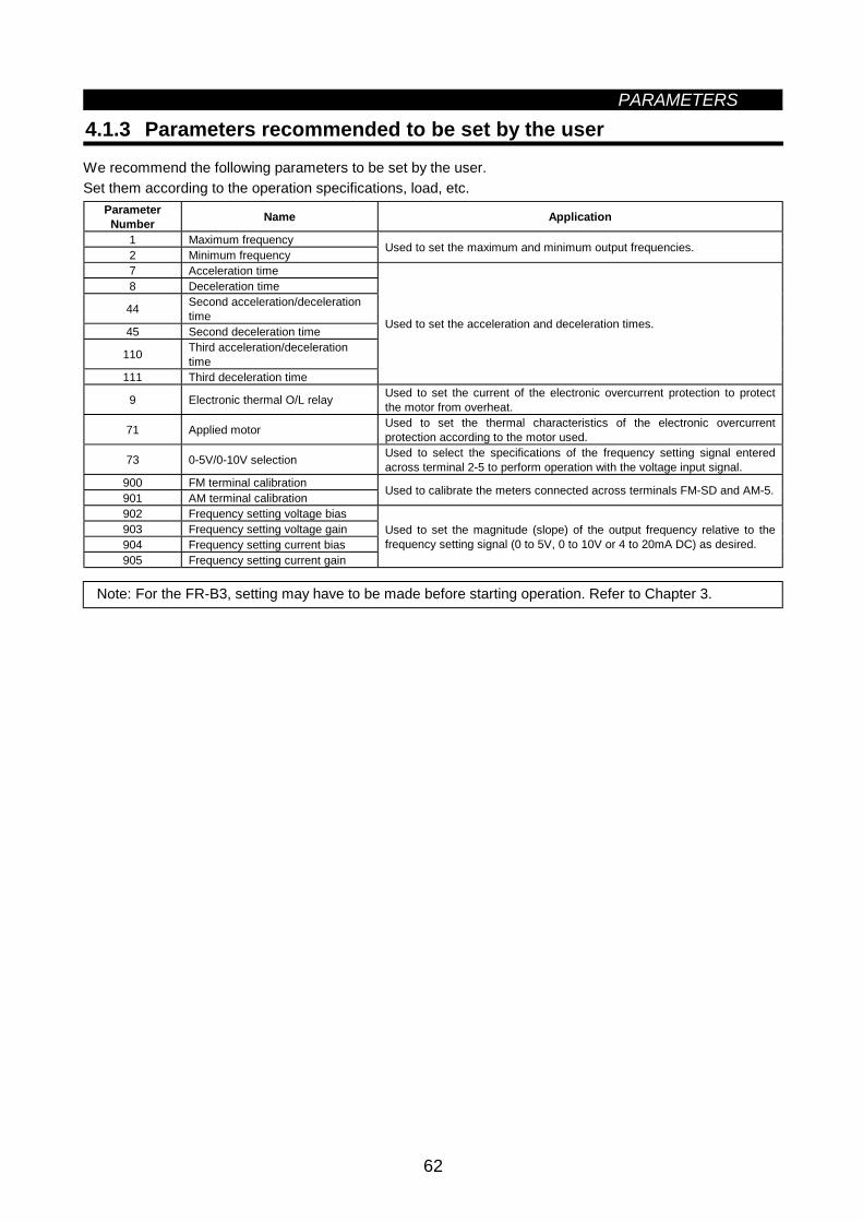
PARAMETERS
62
4.1.3 Parameters recommended to be set by the user
We recommend the following parameters to be set by the user.Set them according to the operation specifications, load, etc.
ParameterNumber Name Application
1 Maximum frequency2 Minimum frequency Used to set the maximum and minimum output frequencies.
7 Acceleration time8 Deceleration time
44 Second acceleration/decelerationtime
45 Second deceleration time
110 Third acceleration/decelerationtime
111 Third deceleration time
Used to set the acceleration and deceleration times.
9 Electronic thermal O/L relay Used to set the current of the electronic overcurrent protection to protectthe motor from overheat.
71 Applied motor Used to set the thermal characteristics of the electronic overcurrentprotection according to the motor used.
73 0-5V/0-10V selection Used to select the specifications of the frequency setting signal enteredacross terminal 2-5 to perform operation with the voltage input signal.
900 FM terminal calibration901 AM terminal calibration Used to calibrate the meters connected across terminals FM-SD and AM-5.
902 Frequency setting voltage bias903 Frequency setting voltage gain904 Frequency setting current bias905 Frequency setting current gain
Used to set the magnitude (slope) of the output frequency relative to thefrequency setting signal (0 to 5V, 0 to 10V or 4 to 20mA DC) as desired.
Note: For the FR-B3, setting may have to be made before starting operation. Refer to Chapter 3.
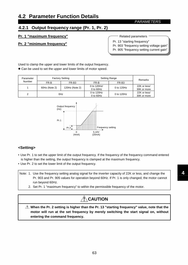
4.2 Parameter Function Details PARAMETERS
63
4.2 Parameter Function Details
4.2.1 Output frequency range (Pr. 1, Pr. 2)
Pr. 1 "maximum frequency"
Pr. 2 "minimum frequency"
Used to clamp the upper and lower limits of the output frequency. Can be used to set the upper and lower limits of motor speed.
Factory Setting Setting RangeParameterNumber FR-B FR-B3 FR-B FR-B3
Remarks
1 60Hz (Note 2) 120Hz (Note 2) 0 to 120Hz/0 to 60Hz 0 to 120Hz 22K or less/
30K or more
2 0Hz 0 to 120Hz0 to 60Hz 0 to 120Hz 22K or less/
30K or more
Pr.1
Pr.2
5,10V0
Frequency setting
Output frequency(Hz)
(20mA)(4mA)
<Setting>
• Use Pr. 1 to set the upper limit of the output frequency. If the frequency of the frequency command enteredis higher than the setting, the output frequency is clamped at the maximum frequency.
• Use Pr. 2 to set the lower limit of the output frequency.
Note: 1. Use the frequency setting analog signal for the inverter capacity of 22K or less, and change thePr. 903 and Pr. 905 values for operation beyond 60Hz. If Pr. 1 is only changed, the motor cannotrun beyond 60Hz.
2. Set Pr. 1 "maximum frequency" to within the permissible frequency of the motor.
CAUTION
When the Pr. 2 setting is higher than the Pr. 13 "starting frequency" value, note that themotor will run at the set frequency by merely switching the start signal on, withoutentering the command frequency.
Pr. 13 "starting frequency"Pr. 903 "frequency setting voltage gain"Pr. 905 "frequency setting current gain"
Related parameters
4
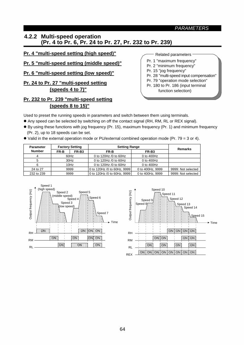
PARAMETERS
64
4.2.2 Multi-speed operation(Pr. 4 to Pr. 6, Pr. 24 to Pr. 27, Pr. 232 to Pr. 239)
Pr. 4 "multi-speed setting (high speed)"
Pr. 5 "multi-speed setting (middle speed)"
Pr. 6 "multi-speed setting (low speed)"
Pr. 24 to Pr. 27 "multi-speed setting (speeds 4 to 7)"
Pr. 232 to Pr. 239 "multi-speed setting (speeds 8 to 15)"
Used to preset the running speeds in parameters and switch between them using terminals. Any speed can be selected by switching on off the contact signal (RH, RM, RL or REX signal). By using these functions with jog frequency (Pr. 15), maximum frequency (Pr. 1) and minimum frequency(Pr. 2), up to 18 speeds can be set. Valid in the external operation mode or PU/external combined operation mode (Pr. 79 = 3 or 4).
Factory Setting Setting RangeParameterNumber FR-B FR-B3 FR-B FR-B3
Remarks
4 60Hz 0 to 120Hz /0 to 60Hz 0 to 400Hz5 30Hz 0 to 120Hz /0 to 60Hz 0 to 400Hz6 10Hz 0 to 120Hz /0 to 60Hz 0 to 400Hz
24 to 27 9999 0 to 120Hz /0 to 60Hz, 9999 0 to 400Hz, 9999 9999: Not selected232 to 239 9999 0 to 120Hz /0 to 60Hz, 9999 0 to 400Hz, 9999 9999: Not selected
ON
ON ON ON ON
ON ON
ONONON
ONRH
RM
RL
Speed 7
Out
put f
requ
ency
(Hz)
Speed 1(high speed)
Speed 2(middle speed)
Speed 3(low speed)
Speed 4
Time
Speed 5
Speed 6
ONON ON ON ON ON ON ON
ON ON ON ON
ON ON ON ON
ON ON ON ONRH
RM
RL
REX
Speed 15
Out
put f
requ
ency
(Hz)
Time
Speed 9Speed 8
Speed 10Speed 11
Speed 12
Speed 13Speed 14
Pr. 1 "maximum frequency"Pr. 2 "minimum frequency"Pr. 15 "jog frequency"Pr. 28 "multi-speed input compensation"Pr. 79 "operation mode selection"Pr. 180 to Pr. 186 (input terminal
function selection)
Related parameters
PARAMETERS
65
<Setting>
• Set the running frequencies in the corresponding parameters.Each speed (frequency) can be set as desired between 0 and 120Hz/0 and 60Hz during inverter operation.After the required multi-speed setting parameter has been read, pressing the [UP/DOWN] key can changethe setting. (In this case, when you release the [UP/DOWN] key, press the [SET] key to store the setfrequency. When using the FR-PU04 (option), press the [WRITE] key.)
• Use any of Pr. 180 to Pr. 186 to assign the terminal used to input the REX signal.
Note: 1. The multi-speed settings override the main speeds (across terminals 2-5, 4-5).2. The multi-speeds can also be set in the PU or external operation mode.3. For 3-speed setting, if two or three speeds are simultaneously selected, priority is given to the
frequency setting of the lower signal.4. Pr. 24 to Pr. 27 and Pr. 232 to Pr. 239 settings have no priority between them.5. The parameter values can be changed during operation.6. When terminal assignment is changed using Pr. 180 to Pr. 186, the other functions may be
affected. Check the functions of the corresponding terminals before making setting.7. For the FR-B series, the setting range depends on the inverter capacity: (22K or less)/(30K or
more).
4
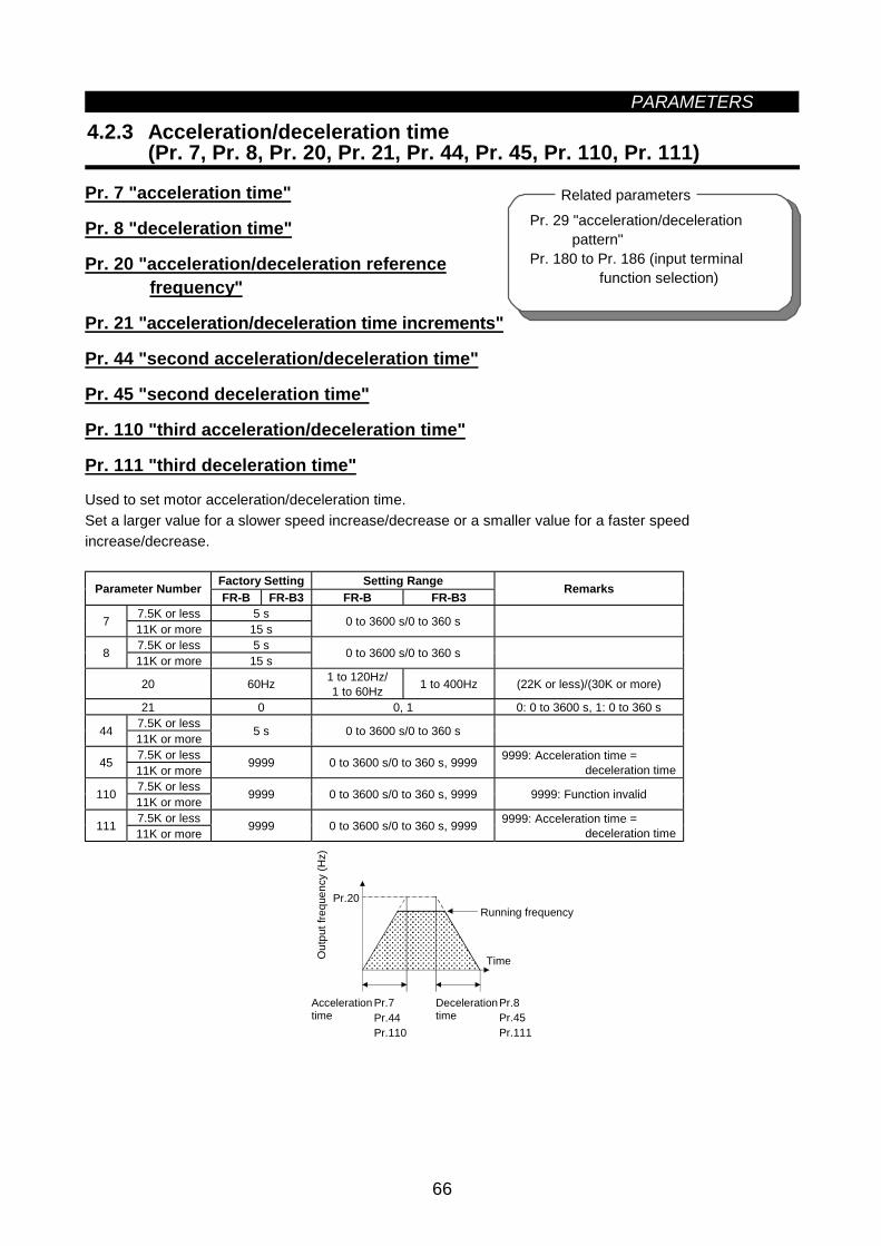
PARAMETERS
66
Pr. 29 "acceleration/decelerationpattern"
Pr. 180 to Pr. 186 (input terminal function selection)
Related parameters
4.2.3 Acceleration/deceleration time(Pr. 7, Pr. 8, Pr. 20, Pr. 21, Pr. 44, Pr. 45, Pr. 110, Pr. 111)
Pr. 7 "acceleration time"
Pr. 8 "deceleration time"
Pr. 20 "acceleration/deceleration reference frequency"
Pr. 21 "acceleration/deceleration time increments"
Pr. 44 "second acceleration/deceleration time"
Pr. 45 "second deceleration time"
Pr. 110 "third acceleration/deceleration time"
Pr. 111 "third deceleration time"
Used to set motor acceleration/deceleration time.Set a larger value for a slower speed increase/decrease or a smaller value for a faster speedincrease/decrease.
Factory Setting Setting RangeParameter NumberFR-B FR-B3 FR-B FR-B3
Remarks
7.5K or less 5 s7 11K or more 15 s 0 to 3600 s/0 to 360 s
7.5K or less 5 s8 11K or more 15 s 0 to 3600 s/0 to 360 s
20 60Hz 1 to 120Hz/1 to 60Hz 1 to 400Hz (22K or less)/(30K or more)
21 0 0, 1 0: 0 to 3600 s, 1: 0 to 360 s7.5K or less44 11K or more 5 s 0 to 3600 s/0 to 360 s
7.5K or less45 11K or more 9999 0 to 3600 s/0 to 360 s, 9999 9999: Acceleration time =deceleration time
7.5K or less110 11K or more 9999 0 to 3600 s/0 to 360 s, 9999 9999: Function invalid
7.5K or less111 11K or more 9999 0 to 3600 s/0 to 360 s, 9999 9999: Acceleration time =deceleration time
Pr.20
Pr.8Pr.45Pr.111
Decelerationtime
Out
put f
requ
ency
(Hz)
Running frequency
Time
Pr.7Pr.44Pr.110
Accelerationtime
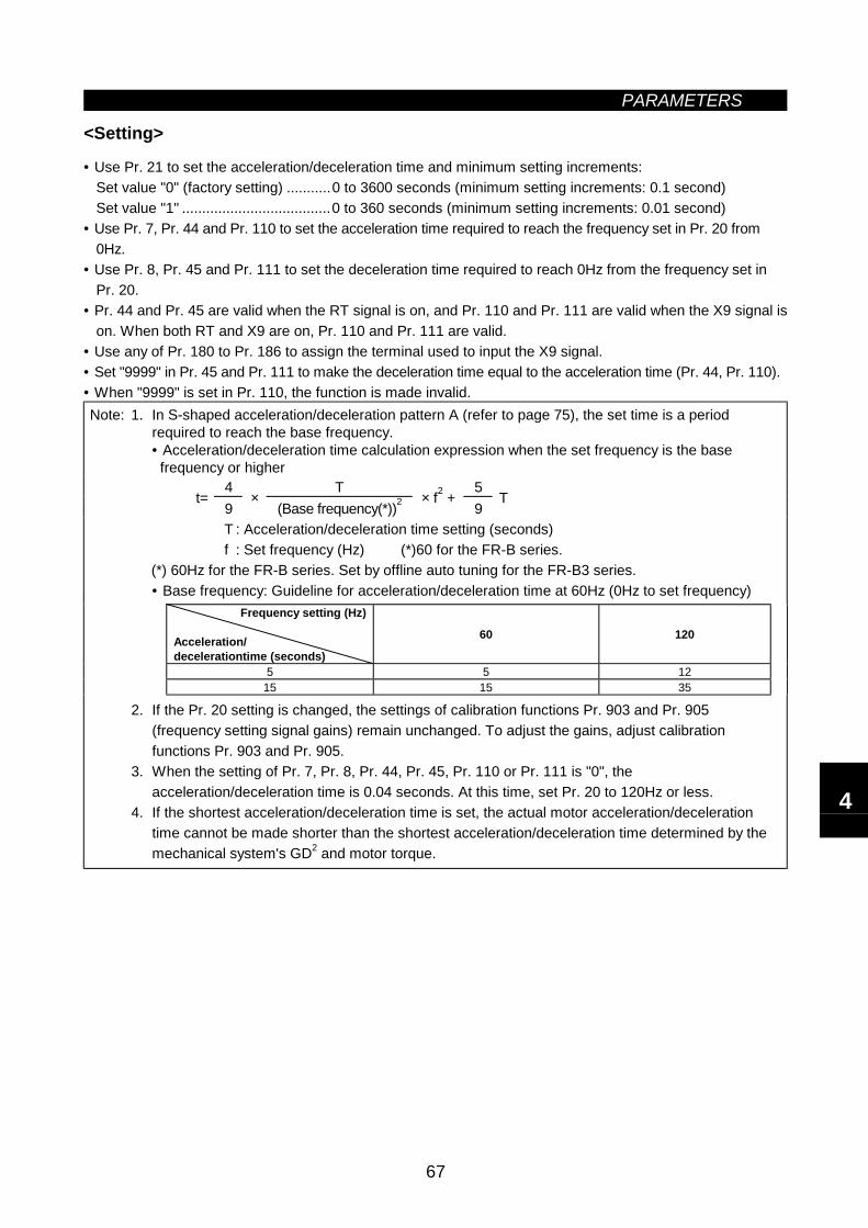
PARAMETERS
67
<Setting>
• Use Pr. 21 to set the acceleration/deceleration time and minimum setting increments:Set value "0" (factory setting) ...........0 to 3600 seconds (minimum setting increments: 0.1 second)Set value "1" .....................................0 to 360 seconds (minimum setting increments: 0.01 second)
• Use Pr. 7, Pr. 44 and Pr. 110 to set the acceleration time required to reach the frequency set in Pr. 20 from0Hz.
• Use Pr. 8, Pr. 45 and Pr. 111 to set the deceleration time required to reach 0Hz from the frequency set inPr. 20.
• Pr. 44 and Pr. 45 are valid when the RT signal is on, and Pr. 110 and Pr. 111 are valid when the X9 signal ison. When both RT and X9 are on, Pr. 110 and Pr. 111 are valid.
• Use any of Pr. 180 to Pr. 186 to assign the terminal used to input the X9 signal.• Set "9999" in Pr. 45 and Pr. 111 to make the deceleration time equal to the acceleration time (Pr. 44, Pr. 110).• When "9999" is set in Pr. 110, the function is made invalid.Note: 1. In S-shaped acceleration/deceleration pattern A (refer to page 75), the set time is a period
required to reach the base frequency.• Acceleration/deceleration time calculation expression when the set frequency is the base frequency or higher
4 T 5t=
9×
(Base frequency(*))2 × f2 +9
T
T : Acceleration/deceleration time setting (seconds)f : Set frequency (Hz) (*)60 for the FR-B series.
(*) 60Hz for the FR-B series. Set by offline auto tuning for the FR-B3 series.• Base frequency: Guideline for acceleration/deceleration time at 60Hz (0Hz to set frequency)
Frequency setting (Hz)
Acceleration/decelerationtime (seconds)
60 120
5 5 1215 15 35
2. If the Pr. 20 setting is changed, the settings of calibration functions Pr. 903 and Pr. 905(frequency setting signal gains) remain unchanged. To adjust the gains, adjust calibrationfunctions Pr. 903 and Pr. 905.
3. When the setting of Pr. 7, Pr. 8, Pr. 44, Pr. 45, Pr. 110 or Pr. 111 is "0", theacceleration/deceleration time is 0.04 seconds. At this time, set Pr. 20 to 120Hz or less.
4. If the shortest acceleration/deceleration time is set, the actual motor acceleration/decelerationtime cannot be made shorter than the shortest acceleration/deceleration time determined by themechanical system's GD2 and motor torque.
4
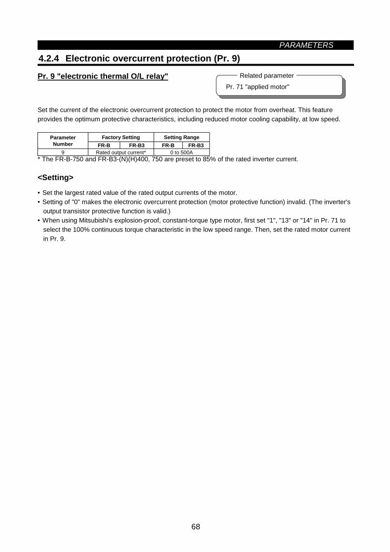
PARAMETERS
68
Pr. 71 "applied motor"
Related parameter
4.2.4 Electronic overcurrent protection (Pr. 9)
Pr. 9 "electronic thermal O/L relay"
Set the current of the electronic overcurrent protection to protect the motor from overheat. This featureprovides the optimum protective characteristics, including reduced motor cooling capability, at low speed.
Factory Setting Setting RangeParameterNumber FR-B FR-B3 FR-B FR-B3
9 Rated output current* 0 to 500A* The FR-B-750 and FR-B3-(N)(H)400, 750 are preset to 85% of the rated inverter current.
<Setting>
• Set the largest rated value of the rated output currents of the motor.• Setting of "0" makes the electronic overcurrent protection (motor protective function) invalid. (The inverter's
output transistor protective function is valid.)• When using Mitsubishi's explosion-proof, constant-torque type motor, first set "1", "13" or "14" in Pr. 71 to
select the 100% continuous torque characteristic in the low speed range. Then, set the rated motor currentin Pr. 9.
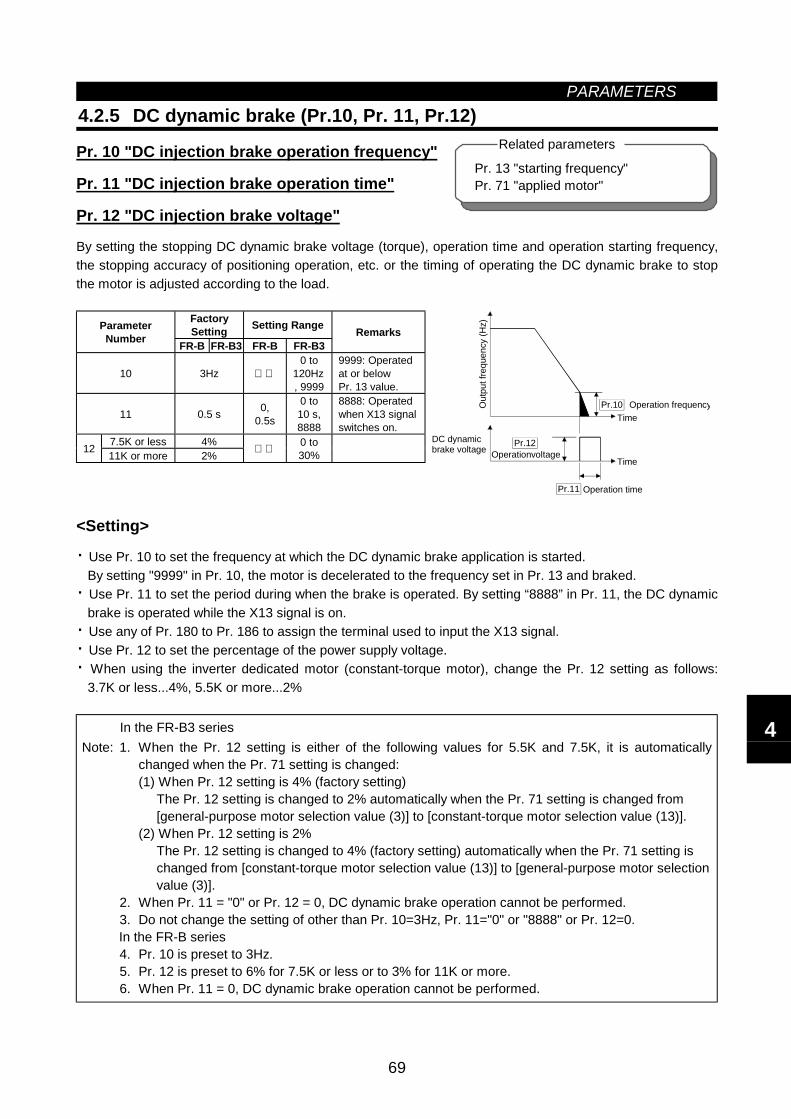
PARAMETERS
69
Pr. 13 "starting frequency"Pr. 71 "applied motor"
Related parameters
4.2.5 DC dynamic brake (Pr.10, Pr. 11, Pr.12)
Pr. 10 "DC injection brake operation frequency"
Pr. 11 "DC injection brake operation time"
Pr. 12 "DC injection brake voltage"
By setting the stopping DC dynamic brake voltage (torque), operation time and operation starting frequency,the stopping accuracy of positioning operation, etc. or the timing of operating the DC dynamic brake to stopthe motor is adjusted according to the load.
FactorySetting Setting RangeParameter
Number FR-B FR-B3 FR-B FR-B3Remarks
10 3Hz 0 to
120Hz, 9999
9999: Operatedat or belowPr. 13 value.
11 0.5 s 0,0.5s
0 to10 s,8888
8888: Operatedwhen X13 signalswitches on.
7.5K or less 4%12 11K or more 2% 0 to30%
Pr.11 Operation timeO
utpu
t fre
quen
cy (H
z)
Operation frequencyTime
DC dynamicbrake voltage Operationvoltage
Time
Pr.12
Pr.10
<Setting>
· Use Pr. 10 to set the frequency at which the DC dynamic brake application is started.By setting "9999" in Pr. 10, the motor is decelerated to the frequency set in Pr. 13 and braked.
· Use Pr. 11 to set the period during when the brake is operated. By setting “8888” in Pr. 11, the DC dynamicbrake is operated while the X13 signal is on.
· Use any of Pr. 180 to Pr. 186 to assign the terminal used to input the X13 signal.· Use Pr. 12 to set the percentage of the power supply voltage.· When using the inverter dedicated motor (constant-torque motor), change the Pr. 12 setting as follows:
3.7K or less...4%, 5.5K or more...2%
In the FR-B3 seriesNote: 1. When the Pr. 12 setting is either of the following values for 5.5K and 7.5K, it is automatically
changed when the Pr. 71 setting is changed:(1) When Pr. 12 setting is 4% (factory setting)
The Pr. 12 setting is changed to 2% automatically when the Pr. 71 setting is changed from[general-purpose motor selection value (3)] to [constant-torque motor selection value (13)].
(2) When Pr. 12 setting is 2%The Pr. 12 setting is changed to 4% (factory setting) automatically when the Pr. 71 setting ischanged from [constant-torque motor selection value (13)] to [general-purpose motor selectionvalue (3)].
2. When Pr. 11 = "0" or Pr. 12 = 0, DC dynamic brake operation cannot be performed.3. Do not change the setting of other than Pr. 10=3Hz, Pr. 11="0" or "8888" or Pr. 12=0.In the FR-B series4. Pr. 10 is preset to 3Hz.5. Pr. 12 is preset to 6% for 7.5K or less or to 3% for 11K or more.6. When Pr. 11 = 0, DC dynamic brake operation cannot be performed.
4
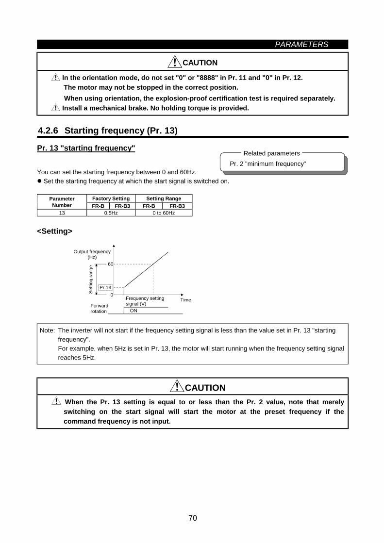
PARAMETERS
70
CAUTION
In the orientation mode, do not set "0" or "8888" in Pr. 11 and "0" in Pr. 12.The motor may not be stopped in the correct position.When using orientation, the explosion-proof certification test is required separately.
Install a mechanical brake. No holding torque is provided.
4.2.6 Starting frequency (Pr. 13)
Pr. 13 "starting frequency"
You can set the starting frequency between 0 and 60Hz. Set the starting frequency at which the start signal is switched on.
Factory Setting Setting RangeParameterNumber FR-B FR-B3 FR-B FR-B3
13 0.5Hz 0 to 60Hz
<Setting>
60
Pr.13
ON
0
Forward rotation
Output frequency (Hz)
Setti
ng ra
nge
Frequency settingsignal (V)
Time
Note: The inverter will not start if the frequency setting signal is less than the value set in Pr. 13 "startingfrequency".For example, when 5Hz is set in Pr. 13, the motor will start running when the frequency setting signalreaches 5Hz.
CAUTION When the Pr. 13 setting is equal to or less than the Pr. 2 value, note that merelyswitching on the start signal will start the motor at the preset frequency if thecommand frequency is not input.
Pr. 2 "minimum frequency"Related parameters
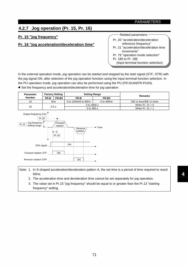
PARAMETERS
71
Pr. 20 "acceleration/decelerationreference frequency"
Pr. 21 "acceleration/deceleration timeincrements"
Pr. 79 "operation mode selection"Pr. 180 to Pr. 186 (input terminal function selection)
Related parameters
4.2.7 Jog operation (Pr. 15, Pr. 16)
Pr. 15 "jog frequency"
Pr. 16 "jog acceleration/deceleration time"
In the external operation mode, jog operation can be started and stopped by the start signal (STF, STR) withthe jog signal ON, after selection of the jog operation function using the input terminal function selection. Inthe PU operation mode, jog operation can also be performed using the PU (FR-DU04/FR-PU04).
Set the frequency and acceleration/deceleration time for jog operation
Factory Setting Setting RangeParameterNumber FR-B FR-B3 FR-B FR-B3
Remarks
15 5Hz 0 to 120Hz/0 to 60Hz 0 to 400Hz 22K or less/30K or more0 to 3600 s When Pr. 21 = 016 0.5 s 0 to 360 s When Pr. 21 = 1
Pr.20
Pr.15
Pr.16
ON
ON
ON
JOG signal
Reverse rotation STR
Output frequency (Hz)
Jog frequencysetting range
Reverserotation
Time
Forwardrotation
Forward rotation STF
Note: 1. In S-shaped acceleration/deceleration pattern A, the set time is a period of time required to reach60Hz.
2. The acceleration time and deceleration time cannot be set separately for jog operation.3. The value set in Pr.15 "jog frequency" should be equal to or greater than the Pr.13 "starting
frequency" setting.
4
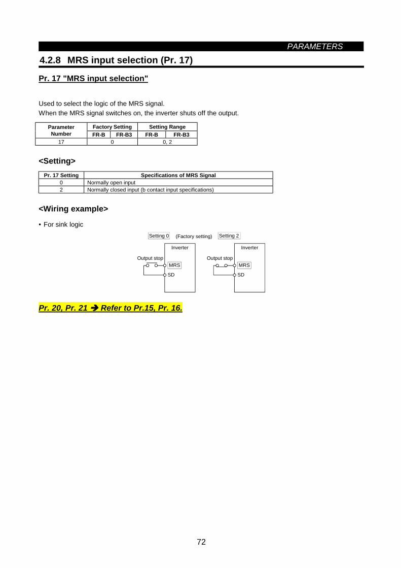
PARAMETERS
72
4.2.8 MRS input selection (Pr. 17)
Pr. 17 "MRS input selection"
Used to select the logic of the MRS signal.When the MRS signal switches on, the inverter shuts off the output.
Factory Setting Setting RangeParameterNumber FR-B FR-B3 FR-B FR-B3
17 0 0, 2
<Setting>Pr. 17 Setting Specifications of MRS Signal
0 Normally open input2 Normally closed input (b contact input specifications)
<Wiring example>
• For sink logic
MRS
SD
MRS
SD
Setting 0 (Factory setting) Setting 2
Output stop Output stop
Inverter Inverter
Pr. 20, Pr. 21 Refer to Pr.15, Pr. 16.
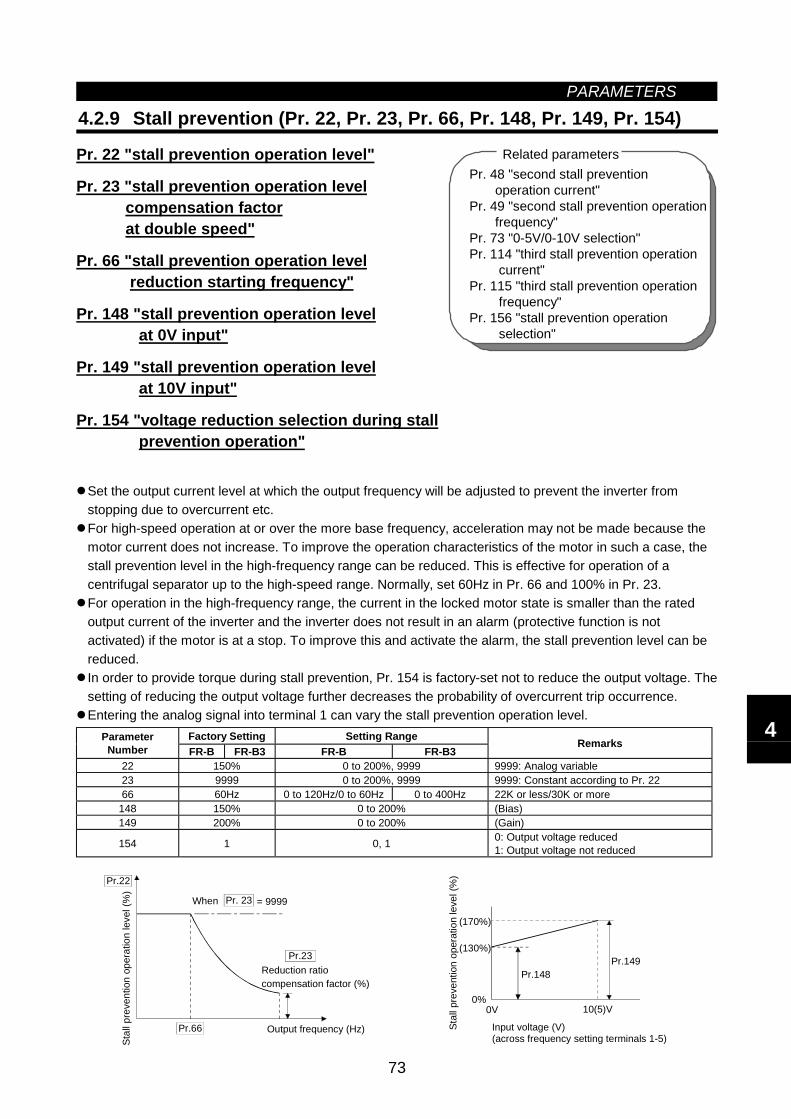
PARAMETERS
73
Pr. 48 "second stall prevention operation current"Pr. 49 "second stall prevention operation frequency"Pr. 73 "0-5V/0-10V selection"Pr. 114 "third stall prevention operation current"Pr. 115 "third stall prevention operation frequency"Pr. 156 "stall prevention operation selection"
Related parameters
4.2.9 Stall prevention (Pr. 22, Pr. 23, Pr. 66, Pr. 148, Pr. 149, Pr. 154)
Pr. 22 "stall prevention operation level"
Pr. 23 "stall prevention operation level compensation factor at double speed"
Pr. 66 "stall prevention operation level reduction starting frequency"
Pr. 148 "stall prevention operation level at 0V input"
Pr. 149 "stall prevention operation level at 10V input"
Pr. 154 "voltage reduction selection during stall prevention operation"
Set the output current level at which the output frequency will be adjusted to prevent the inverter fromstopping due to overcurrent etc.For high-speed operation at or over the more base frequency, acceleration may not be made because themotor current does not increase. To improve the operation characteristics of the motor in such a case, thestall prevention level in the high-frequency range can be reduced. This is effective for operation of acentrifugal separator up to the high-speed range. Normally, set 60Hz in Pr. 66 and 100% in Pr. 23.For operation in the high-frequency range, the current in the locked motor state is smaller than the ratedoutput current of the inverter and the inverter does not result in an alarm (protective function is notactivated) if the motor is at a stop. To improve this and activate the alarm, the stall prevention level can bereduced.In order to provide torque during stall prevention, Pr. 154 is factory-set not to reduce the output voltage. Thesetting of reducing the output voltage further decreases the probability of overcurrent trip occurrence.Entering the analog signal into terminal 1 can vary the stall prevention operation level.
Factory Setting Setting RangeParameterNumber FR-B FR-B3 FR-B FR-B3
Remarks
22 150% 0 to 200%, 9999 9999: Analog variable23 9999 0 to 200%, 9999 9999: Constant according to Pr. 2266 60Hz 0 to 120Hz/0 to 60Hz 0 to 400Hz 22K or less/30K or more
148 150% 0 to 200% (Bias)149 200% 0 to 200% (Gain)
154 1 0, 1 0: Output voltage reduced1: Output voltage not reduced
Pr.22
Pr.23
Pr.66 Output frequency (Hz)
Stal
l pre
vent
ion
oper
atio
n le
vel (
%)
Reduction ratiocompensation factor (%)
Pr. 23 = 9999When
(170%)
(130%)
0%0V
Pr.148Pr.149
10(5)V
Input voltage (V)(across frequency setting terminals 1-5)
Stal
l pre
vent
ion
oper
atio
n le
vel (
%)
4
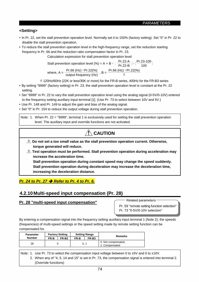
PARAMETERS
74
Pr. 59 "remote setting function selection"Pr. 73 "0-5V/0-10V selection"
Related parameters
<Setting>• In Pr. 22, set the stall prevention operation level. Normally set it to 150% (factory setting). Set "0" in Pr. 22 to
disable the stall prevention operation.• To reduce the stall prevention operation level in the high-frequency range, set the reduction starting
frequency in Pr. 66 and the reduction ratio compensation factor in Pr. 23.Calculation expression for stall prevention operation level
Stall prevention operation level (%) = A + B Pr.22-APr.22-B
Pr.23-100100
where, A = , B = Pr.66 (Hz) Pr.22(%)output frequency (Hz)
Pr.66 (Hz) Pr.22(%)f
f: 120Hz/60Hz (22K or less/30K or more) for the FR-B series, 400Hz for the FR-B3 series• By setting "9999" (factory setting) in Pr. 23, the stall prevention operation level is constant at the Pr. 22
setting.• Set "9999" in Pr. 22 to vary the stall prevention operation level using the analog signal (0-5V/0-10V) entered
to the frequency setting auxiliary input terminal [1]. (Use Pr. 73 to select between 10V and 5V.)• Use Pr. 148 and Pr. 149 to adjust the gain and bias of the analog signal.• Set "0" in Pr. 154 to reduce the output voltage during stall prevention operation.
Note: 1. When Pr. 22 = "9999", terminal 1 is exclusively used for setting the stall prevention operationlevel. The auxiliary input and override functions are not activated.
CAUTION
Do not set a too small value as the stall prevention operation current. Otherwise,torque generated will reduce.
Test operation must be performed. Stall prevention operation during acceleration mayincrease the acceleration time.Stall prevention operation during constant speed may change the speed suddenly.Stall prevention operation during deceleration may increase the deceleration time,increasing the deceleration distance.
Pr. 24 to Pr. 27 Refer to Pr. 4 to Pr. 6.
4.2.10 Multi-speed input compensation (Pr. 28)
Pr. 28 "multi-speed input compensation"
By entering a compensation signal into the frequency setting auxiliary input terminal 1 (Note 2), the speeds(frequencies) of multi-speed settings or the speed setting made by remote setting function can becompensated for.
Factory Setting Setting RangeParameterNumber FR-B FR-B3 FR-B FR-B3
Remarks
28 0 0, 1 0: Not compensated,1: Compensated
Note: 1. Use Pr. 73 to select the compensation input voltage between 0 to ±5V and 0 to ±10V.2. When any of "4, 5, 14 and 15" is set in Pr. 73, the compensation signal is entered into terminal 2.
(Override functions)
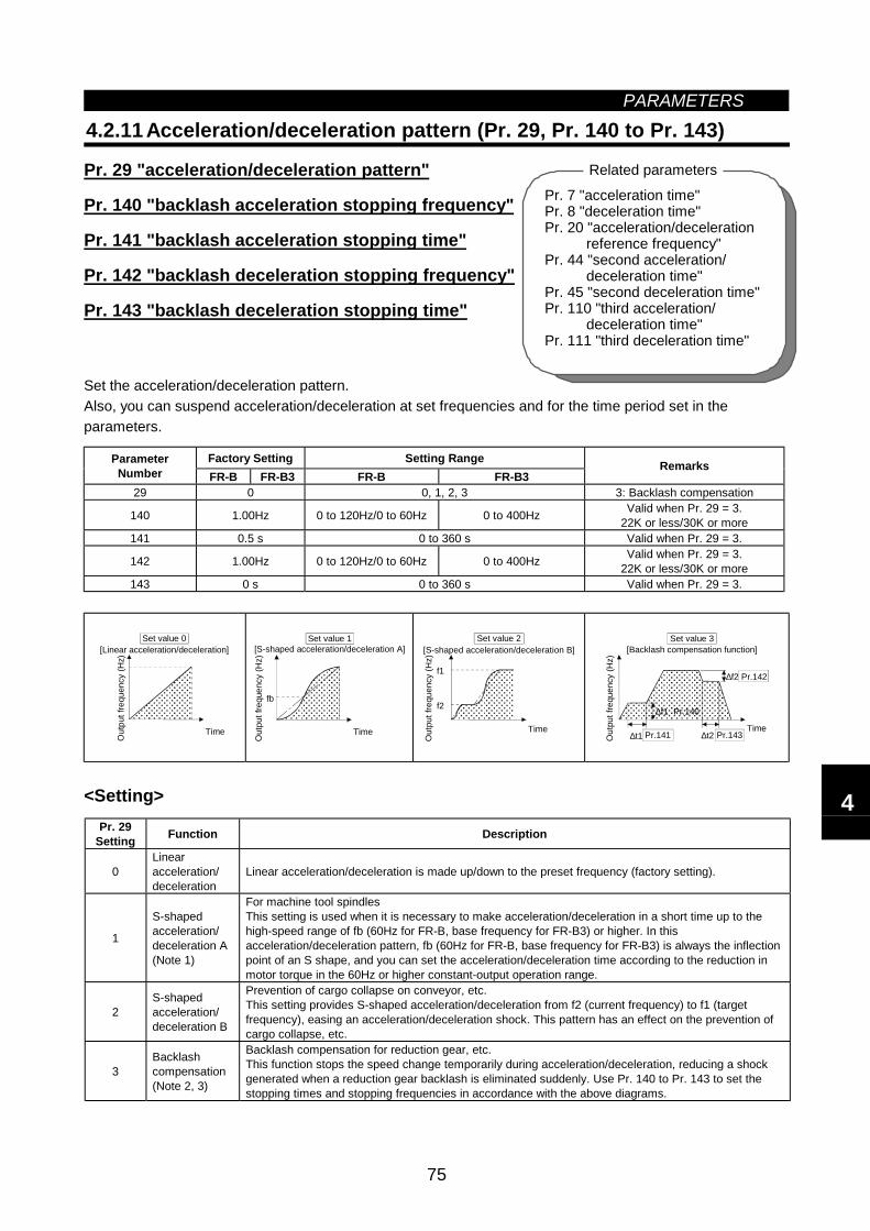
PARAMETERS
75
Pr. 7 "acceleration time"Pr. 8 "deceleration time"Pr. 20 "acceleration/deceleration
reference frequency"Pr. 44 "second acceleration/
deceleration time"Pr. 45 "second deceleration time"Pr. 110 "third acceleration/
deceleration time"Pr. 111 "third deceleration time"
Related parameters
4.2.11 Acceleration/deceleration pattern (Pr. 29, Pr. 140 to Pr. 143)
Pr. 29 "acceleration/deceleration pattern"
Pr. 140 "backlash acceleration stopping frequency"
Pr. 141 "backlash acceleration stopping time"
Pr. 142 "backlash deceleration stopping frequency"
Pr. 143 "backlash deceleration stopping time"
Set the acceleration/deceleration pattern.Also, you can suspend acceleration/deceleration at set frequencies and for the time period set in theparameters.
Factory Setting Setting RangeParameterNumber FR-B FR-B3 FR-B FR-B3
Remarks
29 0 0, 1, 2, 3 3: Backlash compensation
140 1.00Hz 0 to 120Hz/0 to 60Hz 0 to 400Hz Valid when Pr. 29 = 3.22K or less/30K or more
141 0.5 s 0 to 360 s Valid when Pr. 29 = 3.
142 1.00Hz 0 to 120Hz/0 to 60Hz 0 to 400Hz Valid when Pr. 29 = 3.22K or less/30K or more
143 0 s 0 to 360 s Valid when Pr. 29 = 3.
Time
[Linear acceleration/deceleration]
Out
put f
requ
ency
(Hz)
Set value 0
fb
[S-shaped acceleration/deceleration A]
Time
Out
put f
requ
ency
(Hz)
Set value 1
f1
f2
[S-shaped acceleration/deceleration B]
Out
put f
requ
ency
(Hz)
Time
Set value 2
∆f2 Pr.142
∆t2 Pr.143∆t1 Pr.141
∆f1 Pr.140
Out
put f
requ
ency
(Hz)
Set value 3[Backlash compensation function]
Time
<Setting>Pr. 29
Setting Function Description
0Linearacceleration/deceleration
Linear acceleration/deceleration is made up/down to the preset frequency (factory setting).
1
S-shapedacceleration/deceleration A(Note 1)
For machine tool spindlesThis setting is used when it is necessary to make acceleration/deceleration in a short time up to thehigh-speed range of fb (60Hz for FR-B, base frequency for FR-B3) or higher. In thisacceleration/deceleration pattern, fb (60Hz for FR-B, base frequency for FR-B3) is always the inflectionpoint of an S shape, and you can set the acceleration/deceleration time according to the reduction inmotor torque in the 60Hz or higher constant-output operation range.
2S-shapedacceleration/deceleration B
Prevention of cargo collapse on conveyor, etc.This setting provides S-shaped acceleration/deceleration from f2 (current frequency) to f1 (targetfrequency), easing an acceleration/deceleration shock. This pattern has an effect on the prevention ofcargo collapse, etc.
3Backlashcompensation(Note 2, 3)
Backlash compensation for reduction gear, etc.This function stops the speed change temporarily during acceleration/deceleration, reducing a shockgenerated when a reduction gear backlash is eliminated suddenly. Use Pr. 140 to Pr. 143 to set thestopping times and stopping frequencies in accordance with the above diagrams.
4
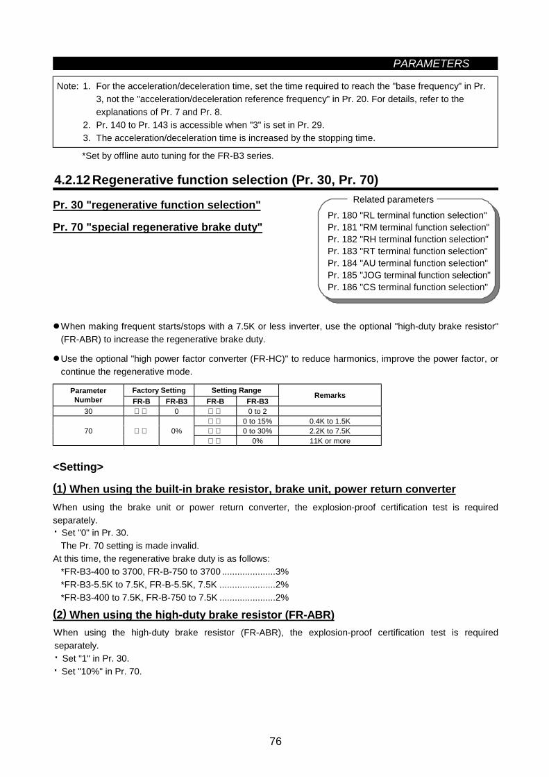
PARAMETERS
76
Pr. 180 "RL terminal function selection"Pr. 181 "RM terminal function selection"Pr. 182 "RH terminal function selection"Pr. 183 "RT terminal function selection"Pr. 184 "AU terminal function selection"Pr. 185 "JOG terminal function selection"Pr. 186 "CS terminal function selection"
Related parameters
Note: 1. For the acceleration/deceleration time, set the time required to reach the "base frequency" in Pr.3, not the "acceleration/deceleration reference frequency" in Pr. 20. For details, refer to theexplanations of Pr. 7 and Pr. 8.
2. Pr. 140 to Pr. 143 is accessible when "3" is set in Pr. 29.3. The acceleration/deceleration time is increased by the stopping time.
*Set by offline auto tuning for the FR-B3 series.
4.2.12 Regenerative function selection (Pr. 30, Pr. 70)
Pr. 30 "regenerative function selection"
Pr. 70 "special regenerative brake duty"
When making frequent starts/stops with a 7.5K or less inverter, use the optional "high-duty brake resistor"(FR-ABR) to increase the regenerative brake duty.
Use the optional "high power factor converter (FR-HC)" to reduce harmonics, improve the power factor, orcontinue the regenerative mode.
Factory Setting Setting RangeParameterNumber FR-B FR-B3 FR-B FR-B3
Remarks
30 0 0 to 2 0 to 15% 0.4K to 1.5K 0 to 30% 2.2K to 7.5K70 0% 0% 11K or more
<Setting>
(1) When using the built-in brake resistor, brake unit, power return converterWhen using the brake unit or power return converter, the explosion-proof certification test is requiredseparately.· Set "0" in Pr. 30.
The Pr. 70 setting is made invalid.At this time, the regenerative brake duty is as follows:
*FR-B3-400 to 3700, FR-B-750 to 3700 .....................3%*FR-B3-5.5K to 7.5K, FR-B-5.5K, 7.5K ......................2%*FR-B3-400 to 7.5K, FR-B-750 to 7.5K ......................2%
(2) When using the high-duty brake resistor (FR-ABR)When using the high-duty brake resistor (FR-ABR), the explosion-proof certification test is requiredseparately.· Set "1" in Pr. 30.· Set "10%" in Pr. 70.
PARAMETERS
77
(3) When using the high power factor converter (FR-HC)When using the high power factor converter (FR-HC), the explosion-proof certification test is requiredseparately, except when using the high power factor converter for power factor improvement.
1) Set "2" in Pr. 30.2) Use any of Pr. 180 to Pr. 186 to assign the following signals to the contact input terminals.
· X10: FR-HC connection (inverter operation enable signal) (Note 3)To make protective coordination with the high power factor converter (FR-HC), use the inverteroperation enable signal to shut off the inverter output. Enter the RDY signal of the high power factorconverter.
· X11: FR-HC connection (instantaneous power failure detection signal)When the computer link inboard option (FR-A5NR) is used and the setting is made to hold the pre-instantaneous power failure mode, use this signal to hold that mode. Enter the instantaneous powerfailure detection signal of the high power factor converter.
3) The Pr. 70 setting is made invalid.* Set "10" and "11" in any of Pr. 180 to Pr. 186 to allocate the terminals used to input the X10 and X11signals.
Note: 1. Cannot be set for the FR-B.2. The Pr. 70 setting is invalid for the FR-B3 inverter of 11K or more.3. Pr. 70 "regenerative brake duty" indicates the %ED of the built-in brake transistor operation. Its
setting should not be higher than the setting of the brake resistor used. Otherwise, the brakeresistor can overheat.
4. The X10 signal may be replaced by the MRS signal.5. When terminal assignment is changed using Pr. 180 to Pr. 186, the other functions may be
affected. Check the functions of the corresponding terminals before making setting.6. When the high power factor converter is used (Pr. 30=2), the deceleration-to-stop functions at
power failure (Pr. 261 to Pr. 266) are invalid.
WARNINGThe Pr. 70 setting must not exceed the setting of the brake resistor used. Otherwise,the brake resistor can overheat. 4
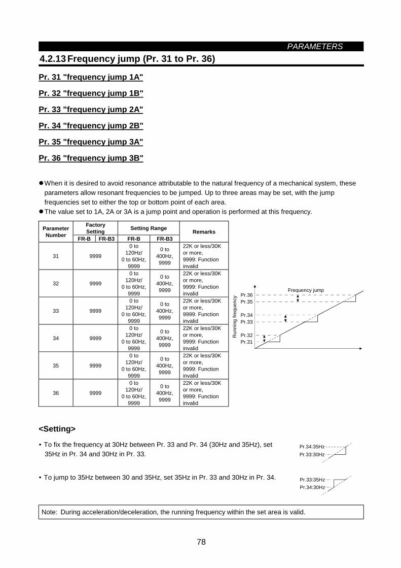
PARAMETERS
78
4.2.13 Frequency jump (Pr. 31 to Pr. 36)
Pr. 31 "frequency jump 1A"
Pr. 32 "frequency jump 1B"
Pr. 33 "frequency jump 2A"
Pr. 34 "frequency jump 2B"
Pr. 35 "frequency jump 3A"
Pr. 36 "frequency jump 3B"
When it is desired to avoid resonance attributable to the natural frequency of a mechanical system, theseparameters allow resonant frequencies to be jumped. Up to three areas may be set, with the jumpfrequencies set to either the top or bottom point of each area.The value set to 1A, 2A or 3A is a jump point and operation is performed at this frequency.
FactorySetting Setting RangeParameter
Number FR-B FR-B3 FR-B FR-B3Remarks
31 9999
0 to120Hz/
0 to 60Hz,9999
0 to400Hz,9999
22K or less/30Kor more,9999: Functioninvalid
32 9999
0 to120Hz/
0 to 60Hz,9999
0 to400Hz,9999
22K or less/30Kor more,9999: Functioninvalid
33 9999
0 to120Hz/
0 to 60Hz,9999
0 to400Hz,9999
22K or less/30Kor more,9999: Functioninvalid
34 9999
0 to120Hz/
0 to 60Hz,9999
0 to400Hz,9999
22K or less/30Kor more,9999: Functioninvalid
35 9999
0 to120Hz/
0 to 60Hz,9999
0 to400Hz,9999
22K or less/30Kor more,9999: Functioninvalid
36 9999
0 to120Hz/
0 to 60Hz,9999
0 to400Hz,9999
22K or less/30Kor more,9999: Functioninvalid
Pr.31Pr.32
Pr.33Pr.34
Pr.35Pr.36
Frequency jump
Run
ning
freq
uenc
y
<Setting>
• To fix the frequency at 30Hz between Pr. 33 and Pr. 34 (30Hz and 35Hz), set35Hz in Pr. 34 and 30Hz in Pr. 33.
Pr.34:35HzPr.33:30Hz
• To jump to 35Hz between 30 and 35Hz, set 35Hz in Pr. 33 and 30Hz in Pr. 34. Pr.33:35HzPr.34:30Hz
Note: During acceleration/deceleration, the running frequency within the set area is valid.
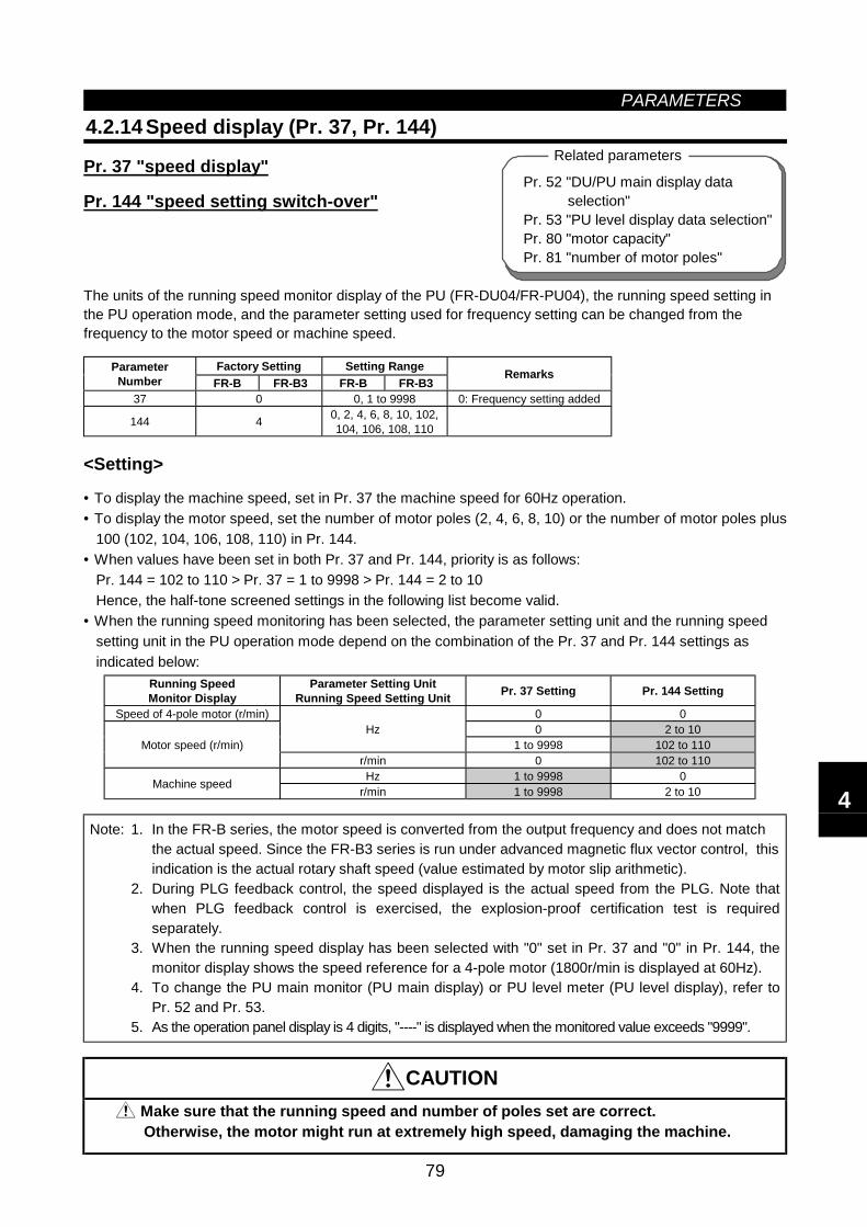
PARAMETERS
79
Pr. 52 "DU/PU main display data selection"Pr. 53 "PU level display data selection"Pr. 80 "motor capacity"Pr. 81 "number of motor poles"
Related parameters
4.2.14 Speed display (Pr. 37, Pr. 144)
Pr. 37 "speed display"
Pr. 144 "speed setting switch-over"
The units of the running speed monitor display of the PU (FR-DU04/FR-PU04), the running speed setting inthe PU operation mode, and the parameter setting used for frequency setting can be changed from thefrequency to the motor speed or machine speed.
Factory Setting Setting RangeParameterNumber FR-B FR-B3 FR-B FR-B3
Remarks
37 0 0, 1 to 9998 0: Frequency setting added
144 4 0, 2, 4, 6, 8, 10, 102,104, 106, 108, 110
<Setting>
• To display the machine speed, set in Pr. 37 the machine speed for 60Hz operation.• To display the motor speed, set the number of motor poles (2, 4, 6, 8, 10) or the number of motor poles plus
100 (102, 104, 106, 108, 110) in Pr. 144.• When values have been set in both Pr. 37 and Pr. 144, priority is as follows:
Pr. 144 = 102 to 110 > Pr. 37 = 1 to 9998 > Pr. 144 = 2 to 10Hence, the half-tone screened settings in the following list become valid.
• When the running speed monitoring has been selected, the parameter setting unit and the running speedsetting unit in the PU operation mode depend on the combination of the Pr. 37 and Pr. 144 settings asindicated below:
Running SpeedMonitor Display
Parameter Setting UnitRunning Speed Setting Unit Pr. 37 Setting Pr. 144 Setting
Speed of 4-pole motor (r/min) 0 00 2 to 10Hz
1 to 9998 102 to 110Motor speed (r/min)r/min 0 102 to 110Hz 1 to 9998 0Machine speed r/min 1 to 9998 2 to 10
Note: 1. In the FR-B series, the motor speed is converted from the output frequency and does not matchthe actual speed. Since the FR-B3 series is run under advanced magnetic flux vector control, thisindication is the actual rotary shaft speed (value estimated by motor slip arithmetic).
2. During PLG feedback control, the speed displayed is the actual speed from the PLG. Note thatwhen PLG feedback control is exercised, the explosion-proof certification test is requiredseparately.
3. When the running speed display has been selected with "0" set in Pr. 37 and "0" in Pr. 144, themonitor display shows the speed reference for a 4-pole motor (1800r/min is displayed at 60Hz).
4. To change the PU main monitor (PU main display) or PU level meter (PU level display), refer toPr. 52 and Pr. 53.
5. As the operation panel display is 4 digits, "----" is displayed when the monitored value exceeds "9999".
CAUTION Make sure that the running speed and number of poles set are correct.Otherwise, the motor might run at extremely high speed, damaging the machine.
4
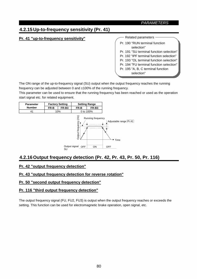
PARAMETERS
80
Pr. 190 "RUN terminal functionselection"
Pr. 191 "SU terminal function selection"Pr. 192 "IPF terminal function selection"Pr. 193 "OL terminal function selection"Pr. 194 "FU terminal function selection"Pr. 195 "A, B, C terminal function
selection"
Related parameters
4.2.15 Up-to-frequency sensitivity (Pr. 41)
Pr. 41 "up-to-frequency sensitivity"
The ON range of the up-to-frequency signal (SU) output when the output frequency reaches the runningfrequency can be adjusted between 0 and ±100% of the running frequency.This parameter can be used to ensure that the running frequency has been reached or used as the operationstart signal etc. for related equipment.
Factory Setting Setting RangeParameterNumber FR-B FR-B3 FR-B FR-B3
41 10% 0 to 100%
ON
Pr.41
Output signalSU
Out
put f
requ
ency
(Hz)
Running frequencyAdjustable range
Time
OFF OFF
4.2.16 Output frequency detection (Pr. 42, Pr. 43, Pr. 50, Pr. 116)
Pr. 42 "output frequency detection"
Pr. 43 "output frequency detection for reverse rotation"
Pr. 50 "second output frequency detection"
Pr. 116 "third output frequency detection"
The output frequency signal (FU, FU2, FU3) is output when the output frequency reaches or exceeds thesetting. This function can be used for electromagnetic brake operation, open signal, etc.
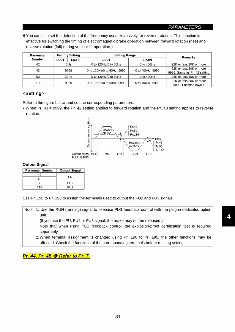
PARAMETERS
81
You can also set the detection of the frequency used exclusively for reverse rotation. This function iseffective for switching the timing of electromagnetic brake operation between forward rotation (rise) andreverse rotation (fall) during vertical lift operation, etc.
Factory Setting Setting RangeParameterNumber FR-B FR-B3 FR-B FR-B3
Remarks
42 6Hz 0 to 120Hz/0 to 60Hz 0 to 400Hz 22K or less/30K or more
43 9999 0 to 120Hz/0 to 60Hz, 9999 0 to 400Hz, 9999 22K or less/30K or more9999: Same as Pr. 42 setting
50 30Hz 0 to 120Hz/0 to 60Hz 0 to 400Hz 22K or less/30K or more
116 9999 0 to 120Hz/0 to 60Hz, 9999 0 to 400Hz, 9999 22K or less/30K or more9999: Function invalid
<Setting>
Refer to the figure below and set the corresponding parameters:• When Pr. 43 ≠ 9999, the Pr. 42 setting applies to forward rotation and the Pr. 43 setting applies to reverse
rotation.
Pr.50Pr.42
Pr.116
Pr.50Pr.43
Pr.116Output signalFU,FU2,FU3
Out
put f
requ
ency
(Hz)
Forwardrotation
Reverserotation
Time
OFF OFF OFFON ON
Output SignalParameter Number Output Signal
4243 FU
50 FU2116 FU3
Use Pr. 190 to Pr. 195 to assign the terminals used to output the FU2 and FU3 signals.
Note: 1. Use the RUN (running) signal to exercise PLG feedback control with the plug-in dedicated optionunit.(If you use the FU, FU2 or FU3 signal, the brake may not be released.)Note that when using PLG feedback control, the explosion-proof certification test is requiredseparately.
2.When terminal assignment is changed using Pr. 190 to Pr. 195, the other functions may beaffected. Check the functions of the corresponding terminals before making setting.
Pr. 44, Pr. 45 Refer to Pr. 7.
4
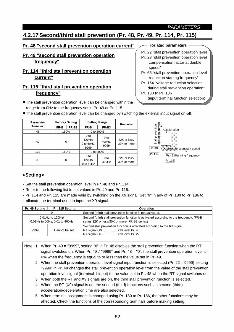
PARAMETERS
82
4.2.17 Second/third stall prevention (Pr. 48, Pr. 49, Pr. 114, Pr. 115)
Pr. 48 "second stall prevention operation current"
Pr. 49 "second stall prevention operation frequency"
Pr. 114 "third stall prevention operation current"
Pr. 115 "third stall prevention operation frequency"
The stall prevention operation level can be changed within therange from 0Hz to the frequency set in Pr. 49 or Pr. 115. The stall prevention operation level can be changed by switching the external input signal on-off.
Factory Setting Setting RangeParameterNumber FR-B FR-B3 FR-B FR-B3
Remarks
48 150% 0 to 200%
49 0
0 to120Hz/
0 to 60Hz,9999
0 to400Hz,9999
22K or less/30K or more
114 150% 0 to 200%
115 00 to
120Hz/0 to 60Hz
0 to400Hz
22K or less/30K or more
Running frequencySt
all p
reve
ntio
nop
erat
ion
curre
nt
Acceleration
Deceleration/constant speed
Pr.49
Pr.115
Pr.114
Pr.48
<Setting>
• Set the stall prevention operation level in Pr. 48 and Pr. 114.• Refer to the following list to set values in Pr. 49 and Pr. 115.• Pr. 114 and Pr. 115 are made valid by switching on the X9 signal. Set "9" in any of Pr. 180 to Pr. 186 to
allocate the terminal used to input the X9 signal.
Pr. 49 Setting Pr. 115 Setting Operation0 Second (third) stall prevention function is not activated.
0.01Hz to 120Hz/0.01Hz to 60Hz, 0.01 to 400Hz
Second (third) stall prevention function is activated according to the frequency. (FR-Bseries 22K or less/30K or more, FR-B3 series)
9999 Cannot be set.Second stall prevention function is activated according to the RT signal.RT signal ON............... Stall level Pr. 48RT signal OFF ............. Stall level Pr. 22
Note: 1. When Pr. 49 = "9999", setting "0" in Pr. 48 disables the stall prevention function when the RTsignal switches on. When Pr. 49 ≠ "9999" and Pr. 48 = "0", the stall prevention operation level is0% when the frequency is equal to or less than the value set in Pr. 49.
2. When the stall prevention operation level signal input function is selected (Pr. 22 = 9999), setting"9999" in Pr. 49 changes the stall prevention operation level from the value of the stall preventionoperation level signal (terminal 1 input) to the value set in Pr. 48 when the RT signal switches on.
3. When both the RT and X9 signals are on, the third stall prevention function is selected.4. When the RT (X9) signal is on, the second (third) functions such as second (third)
acceleration/deceleration time are also selected.5. When terminal assignment is changed using Pr. 180 to Pr. 186, the other functions may be
affected. Check the functions of the corresponding terminals before making setting.
Pr. 22 "stall prevention operation level"Pr. 23 "stall prevention operation level compensation factor at double speed"Pr. 66 "stall prevention operation level reduction starting frequency"Pr. 154 "voltage reduction selection during stall prevention operation"Pr. 180 to Pr. 186 (input terminal function selection)
Related parameters
PARAMETERS
83
Pr. 37 "speed display"Pr. 55 "frequency monitoring reference"Pr. 56 "current monitoring reference"Pr. 170 "watt-hour meter clear"Pr. 171 "actual operation hour meter clear"Pr. 900 "FM terminal calibration"Pr. 901 "AM terminal calibration"
Related parameters
CAUTION Do not set a too small value to the second (third) stall prevention operation current.Otherwise, torque generated will decrease.
Pr. 50 Refer to Pr. 42.
4.2.18 Monitor display/FM, AM terminal function selection(Pr. 52 to Pr. 54, Pr. 158)
Pr. 52 "DU/PU main display data selection"
Pr. 53 "PU level display data selection"
Pr. 54 "FM terminal function selection"
Pr. 158 "AM terminal function selection"
You can select the signals shown on the operation panel (FR-DU04)/parameter unit (FR-PU04) main displayscreen and on the parameter unit (FR-PU04) level meter and signals output to the FM and AM terminals.
There are two different signal outputs: FM pulse train output terminal and AM analog output terminal. Selectthe signals using Pr. 54 and Pr. 158.
Factory Setting Setting RangeParameterNumber FR-B FR-B3 FR-B FR-B3
52 0 0, 5, 6, 8, 10 to 14, 17 to 20, 22 to25, 100
0 to 20, 22 to 25, 100
53 1 0 to 3, 5, 6, 8, 10 to 14, 17, 18, 21 0 to 3, 5 to 14, 17, 1854 1 1 to 3, 5, 6, 8, 10 to 14, 17, 18, 21 1 to 3, 5 to 14, 17, 18, 21
158 1 1 to 3, 5, 6, 8, 10 to 14, 17, 18, 21 1 to 3, 5 to 14, 17, 18, 21
4
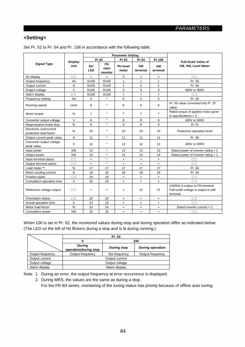
PARAMETERS
84
<Setting>
Set Pr. 52 to Pr. 54 and Pr. 158 in accordance with the following table:
Parameter SettingPr.52 Pr.53 Pr.54 Pr.158
Signal Type DisplayUnit DU
LED
PUmain
monitor
PU levelmeter
FMterminal
AMterminal
Full-Scale Value ofFM, AM, Level Meter
No display × × 0 × × Output frequency Hz 0/100 0/100 1 1 1 Pr. 55Output current A 0/100 0/100 2 2 2 Pr. 56Output voltage V 0/100 0/100 3 3 3 400V or 800VAlarm display 0/100 0/100 × × × Frequency setting Hz 5 * 5 5 5 Pr. 55
Running speed r/min 6 * 6 6 6 Pr. 55 value converted into Pr. 37value
Motor torque % 7 * 7 7 7 Rated torque of applied motor givenin specifications × 2
Converter output voltage V 8 * 8 8 8 400V or 800VRegenerative brake duty % 9 * 9 9 9 Pr.70Electronic overcurrentprotection load factor % 10 * 10 10 10 Protection operation level
Output current peak value A 11 * 11 11 11 Pr. 56Converter output voltagepeak value V 12 * 12 12 12 400V or 800V
Input power kW 13 * 13 13 13 Rated power of inverter rating × 2Output power kW 14 * 14 14 14 Rated power of inverter rating × 2Input terminal status × * × × × Output terminal status × * × × × Load meter ** % 17 17 17 17 17 Pr. 56Motor exciting current A 18 18 18 18 18 Pr. 56Position pulse 19 19 × × × Cumulative operation time h 20 20 × × ×
Reference voltage output × × × 21 211440Hz is output to FM terminal.Full-scale voltage is output to AMterminal.
Orientation status 22 22 × × × Actual operation time h 23 23 × × × Motor load factor % 24 24 × × × Rated inverter current × 2Cumulative power kW 25 25 × × ×
When 100 is set in Pr. 52, the monitored values during stop and during operation differ as indicated below:(The LED on the left of Hz flickers during a stop and is lit during running.)
Pr. 520 100
Duringoperation/during stop During stop During operation
Output frequency Output frequency Set frequency Output frequencyOutput current Output currentOutput voltage Output voltageAlarm display Alarm display
Note: 1. During an error, the output frequency at error occurrence is displayed.2. During MRS, the values are the same as during a stop.
For the FR-B3 series, monitoring of the tuning status has priority because of offline auto tuning.
PARAMETERS
85
In the FR-B3 seriesNote: 1. The monitoring of items marked × cannot be selected.
2. By setting "0" in Pr. 52, the monitoring of "output frequency to alarm display" can be selected insequence by the SHIFT key.
3. *"Frequency setting to output terminal status" on the PU main monitor are selected by "othermonitor selection" of the parameter unit (FR-PU04).
4. **The load meter is displayed in %, with the current set in Pr. 56 regarded as 100%.5. The actual operation time displayed by setting "23" in Pr. 52 is calculated using the inverter
operation time. (Inverter stop time is not included.) Set "0" in Pr. 171 to clear it.6. When Pr. 53 = "0", the level meter display of the parameter unit can be erased.7. By setting "1, 2, 5, 6, 11, 17 or 18" in Pr. 53, the full-scale value can be set in Pr. 55 or Pr. 56.8. The cumulative operation time and actual operation time are calculated from 0 to 65535 hours,
then cleared, and recalculated from 0.When the operation panel (FR-DU04) is used, the display shows "----" after 9999 or more hourshave elapsed.Whether 9999 or more hours have elapsed or not can be confirmed on the parameter unit(FR-PU04).
9. The actual operation time is not calculated unless the inverter has operated for longer than onehour continuously.
10. When the operation panel (FR-DU04) is used, the display unit is Hz, V or A only.11. The orientation status functions when the FR-A5AP option is used. If the option is not used, "22"
may be set in Pr. 52 and the value displayed remains "0" and the function is invalid.When using orientation, the explosion-proof certification test is required separately.
In the FR-B seriesNote: 1. The monitoring of items marked × cannot be selected.
2. By setting "0" in Pr. 52, the monitoring of "output frequency to alarm display" can be selected insequence by the SHIFT key.
3. *"Frequency setting to output terminal status" on the PU main monitor are selected by "othermonitor selection" of the parameter unit (FR-PU04).
4. **The load meter is displayed in %, with the current set in Pr. 56 regarded as 100%.5. The motor torque and regenerative brake duty cannot be set.6. The actual operation time displayed by setting "23" in Pr. 52 is calculated using the inverter
operation time. (Inverter stop time is not included.) Set "0" in Pr. 171 to clear it.7. When Pr. 53 = "0", the level meter display of the parameter unit can be erased.8. By setting "1, 2, 5, 6, 11, 17 or 18" in Pr. 53, the full-scale value can be set in Pr. 55 or Pr. 56.9. The cumulative operation time and actual operation time are calculated from 0 to 65535 hours,
then cleared, and recalculated from 0.When the operation panel (FR-DU04) is used, the display shows "----" after 9999 or more hourshave elapsed.Whether 9999 or more hours have elapsed or not can be confirmed on the parameter unit(FR-PU04).
10. The actual operation time is not calculated unless the inverter has operated for longer than onehour continuously.
11. When the operation panel (FR-DU04) is used, the display unit is Hz, V or A only.12. The orientation status functions when the FR-A5AP option is used. If the option is not used, "22"
may be set in Pr. 52 and the value displayed remains "0" and the function is invalid.When using orientation, the explosion-proof certification test is required separately.
4
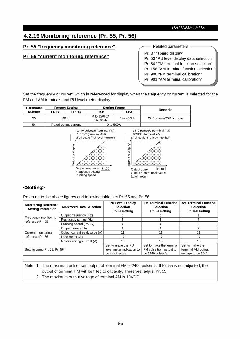
PARAMETERS
86
Pr. 37 "speed display"Pr. 53 "PU level display data selection"Pr. 54 "FM terminal function selection"Pr. 158 "AM terminal function selection"Pr. 900 "FM terminal calibration"Pr. 901 "AM terminal calibration"
Related parameters
4.2.19 Monitoring reference (Pr. 55, Pr. 56)
Pr. 55 "frequency monitoring reference"
Pr. 56 "current monitoring reference"
Set the frequency or current which is referenced for display when the frequency or current is selected for theFM and AM terminals and PU level meter display.
Factory Setting Setting RangeParameterNumber FR-B FR-B3 FR-B FR-B3 Remarks
55 60Hz 0 to 120Hz/0 to 60Hz 0 to 400Hz 22K or less/30K or more
56 Rated output current 0 to 500A
Pr.55
Out
put o
r dis
play
Output frequencyFrequency settingRunning speed
Pr.56
1440 pulses/s (terminal FM)10VDC (terminal AM)Full scale (PU level monitor)
Out
put o
r dis
play
Output currentOutput current peak valueLoad meter
1440 pulses/s (terminal FM)10VDC (terminal AM)Full scale (PU level monitor)
<Setting>
Referring to the above figures and following table, set Pr. 55 and Pr. 56:
Monitoring ReferenceSetting Parameter Monitored Data Selection
PU Level DisplaySelection
Pr. 53 Setting
FM Terminal FunctionSelection
Pr. 54 Setting
AM Terminal FunctionSelection
Pr. 158 SettingOutput frequency (Hz) 1 1 1Frequency setting (Hz) 5 5 5Frequency monitoring
reference Pr. 55Running speed (Pr. 37) 6 6 6Output current (A) 2 2 2Output current peak value (A) 11 11 11Load meter (A) 17 17 17
Current monitoringreference Pr. 56
Motor exciting current (A) 18 18 18
Setting using Pr. 55, Pr. 56Set to make the PUlevel meter indication tobe in full-scale.
Set to make the terminalFM pulse train output tobe 1440 pulses/s.
Set to make theterminal AM outputvoltage to be 10V.
Note: 1. The maximum pulse train output of terminal FM is 2400 pulses/s. If Pr. 55 is not adjusted, theoutput of terminal FM will be filled to capacity. Therefore, adjust Pr. 55.
2. The maximum output voltage of terminal AM is 10VDC.
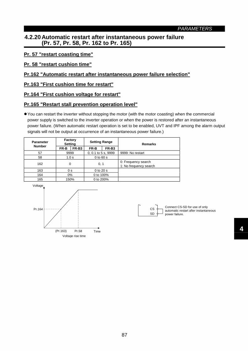
PARAMETERS
87
4.2.20 Automatic restart after instantaneous power failure(Pr. 57, Pr. 58, Pr. 162 to Pr. 165)
Pr. 57 "restart coasting time"
Pr. 58 "restart cushion time"
Pr.162 "Automatic restart after instantaneous power failure selection"
Pr.163 "First cushion time for restart"
Pr.164 "First cushion voltage for restart"
Pr.165 "Restart stall prevention operation level"
You can restart the inverter without stopping the motor (with the motor coasting) when the commercialpower supply is switched to the inverter operation or when the power is restored after an instantaneouspower failure. (When automatic restart operation is set to be enabled, UVT and IPF among the alarm outputsignals will not be output at occurrence of an instantaneous power failure.)
FactorySetting Setting RangeParameter
Number FR-B FR-B3 FR-B FR-B3Remarks
57 9999 0, 0.1 to 5 s, 9999 9999: No restart58 1.0 s 0 to 60 s
162 0 0, 1 0: Frequency search1: No frequency search
163 0 s 0 to 20 s164 0% 0 to 100%165 150% 0 to 200%
CSSD
Connect CS-SD for use of onlyautomatic restart after instantaneous power failure.
(Pr.163) Pr.58
Pr.164
Voltage
TimeVoltage rise time
4
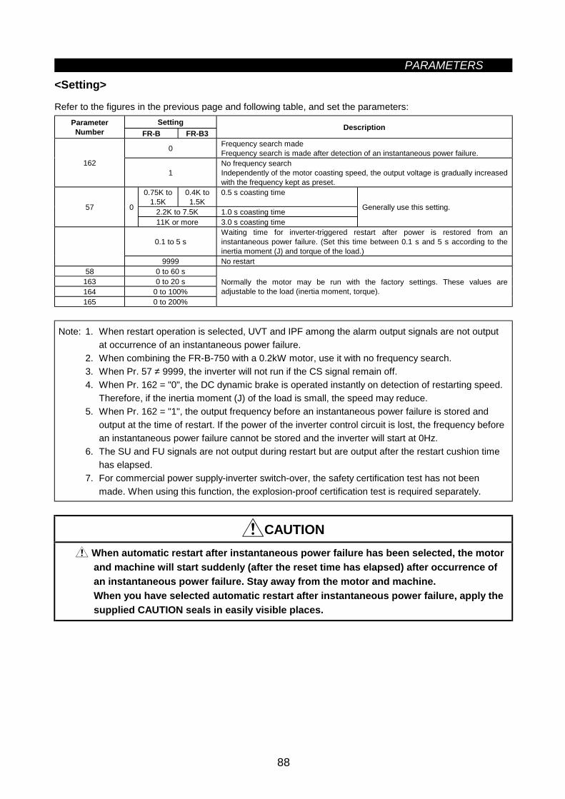
PARAMETERS
88
<Setting>
Refer to the figures in the previous page and following table, and set the parameters:SettingParameter
Number FR-B FR-B3Description
0 Frequency search madeFrequency search is made after detection of an instantaneous power failure.
1621
No frequency searchIndependently of the motor coasting speed, the output voltage is gradually increasedwith the frequency kept as preset.
0.75K to1.5K
0.4K to1.5K
0.5 s coasting time
2.2K to 7.5K 1.0 s coasting time57 0
11K or more 3.0 s coasting time
Generally use this setting.
0.1 to 5 sWaiting time for inverter-triggered restart after power is restored from aninstantaneous power failure. (Set this time between 0.1 s and 5 s according to theinertia moment (J) and torque of the load.)
9999 No restart58 0 to 60 s
163 0 to 20 s164 0 to 100%165 0 to 200%
Normally the motor may be run with the factory settings. These values areadjustable to the load (inertia moment, torque).
Note: 1. When restart operation is selected, UVT and IPF among the alarm output signals are not outputat occurrence of an instantaneous power failure.
2. When combining the FR-B-750 with a 0.2kW motor, use it with no frequency search.3. When Pr. 57 ≠ 9999, the inverter will not run if the CS signal remain off.4. When Pr. 162 = "0", the DC dynamic brake is operated instantly on detection of restarting speed.
Therefore, if the inertia moment (J) of the load is small, the speed may reduce.5. When Pr. 162 = "1", the output frequency before an instantaneous power failure is stored and
output at the time of restart. If the power of the inverter control circuit is lost, the frequency beforean instantaneous power failure cannot be stored and the inverter will start at 0Hz.
6. The SU and FU signals are not output during restart but are output after the restart cushion timehas elapsed.
7. For commercial power supply-inverter switch-over, the safety certification test has not beenmade. When using this function, the explosion-proof certification test is required separately.
CAUTION When automatic restart after instantaneous power failure has been selected, the motorand machine will start suddenly (after the reset time has elapsed) after occurrence ofan instantaneous power failure. Stay away from the motor and machine.When you have selected automatic restart after instantaneous power failure, apply thesupplied CAUTION seals in easily visible places.
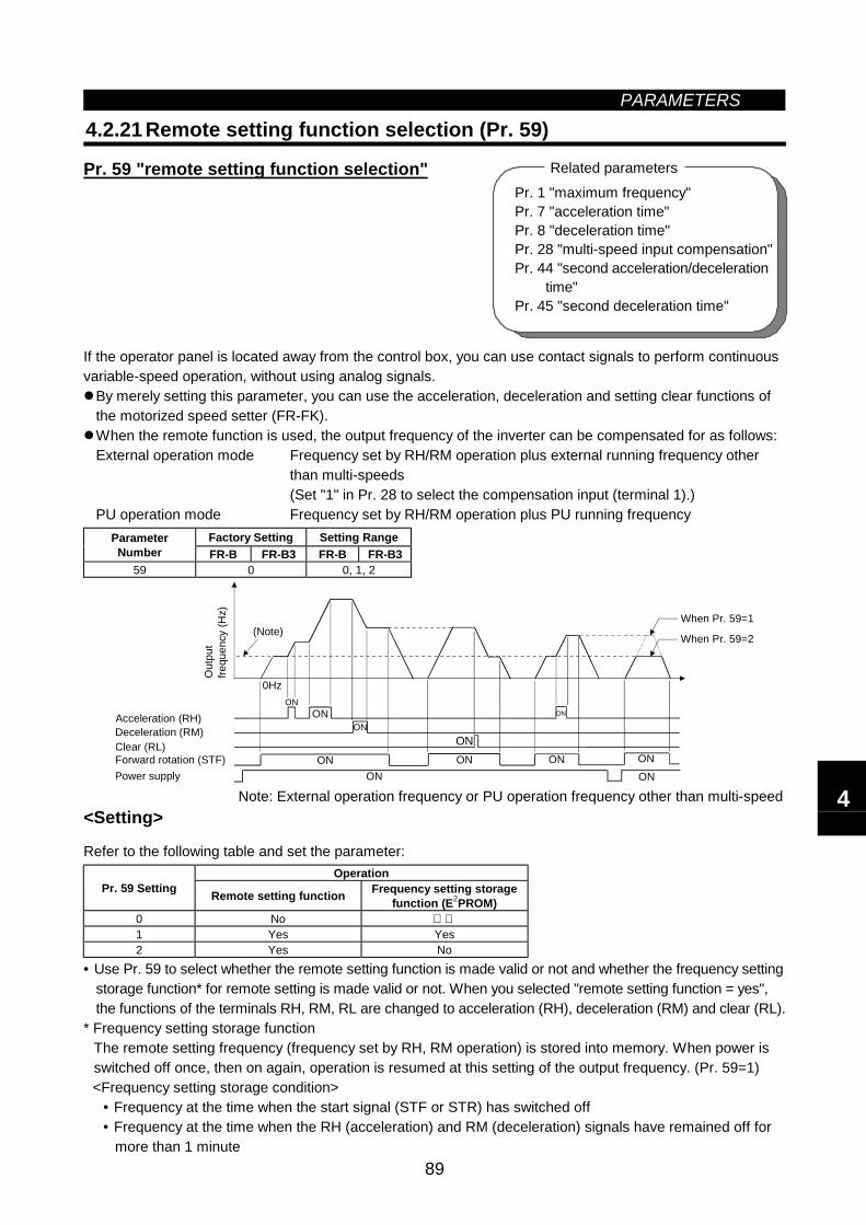
PARAMETERS
89
4.2.21 Remote setting function selection (Pr. 59)
Pr. 59 "remote setting function selection"
If the operator panel is located away from the control box, you can use contact signals to perform continuousvariable-speed operation, without using analog signals.
By merely setting this parameter, you can use the acceleration, deceleration and setting clear functions ofthe motorized speed setter (FR-FK). When the remote function is used, the output frequency of the inverter can be compensated for as follows:External operation mode Frequency set by RH/RM operation plus external running frequency other
than multi-speeds(Set "1" in Pr. 28 to select the compensation input (terminal 1).)
PU operation mode Frequency set by RH/RM operation plus PU running frequencyFactory Setting Setting RangeParameter
Number FR-B FR-B3 FR-B FR-B359 0 0, 1, 2
Deceleration (RM)Clear (RL)
Acceleration (RH)
Forward rotation (STF) ON ONPower supply ON
0Hz
(Note)
ONON
ONON
ON
ON
When Pr. 59=1
When Pr. 59=2
ON
ON
Out
put
frequ
ency
(Hz)
Note: External operation frequency or PU operation frequency other than multi-speed<Setting>
Refer to the following table and set the parameter:Operation
Pr. 59 Setting Remote setting function Frequency setting storagefunction (E2PROM)
0 No 1 Yes Yes2 Yes No
• Use Pr. 59 to select whether the remote setting function is made valid or not and whether the frequency settingstorage function* for remote setting is made valid or not. When you selected "remote setting function = yes",the functions of the terminals RH, RM, RL are changed to acceleration (RH), deceleration (RM) and clear (RL).
* Frequency setting storage functionThe remote setting frequency (frequency set by RH, RM operation) is stored into memory. When power isswitched off once, then on again, operation is resumed at this setting of the output frequency. (Pr. 59=1)<Frequency setting storage condition>
• Frequency at the time when the start signal (STF or STR) has switched off• Frequency at the time when the RH (acceleration) and RM (deceleration) signals have remained off for
more than 1 minute
Pr. 1 "maximum frequency"Pr. 7 "acceleration time"Pr. 8 "deceleration time"Pr. 28 "multi-speed input compensation"Pr. 44 "second acceleration/deceleration time"Pr. 45 "second deceleration time"
Related parameters
4
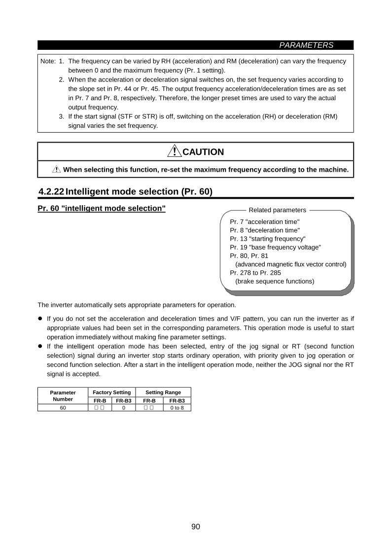
PARAMETERS
90
Note: 1. The frequency can be varied by RH (acceleration) and RM (deceleration) can vary the frequencybetween 0 and the maximum frequency (Pr. 1 setting).
2. When the acceleration or deceleration signal switches on, the set frequency varies according tothe slope set in Pr. 44 or Pr. 45. The output frequency acceleration/deceleration times are as setin Pr. 7 and Pr. 8, respectively. Therefore, the longer preset times are used to vary the actualoutput frequency.
3. If the start signal (STF or STR) is off, switching on the acceleration (RH) or deceleration (RM)signal varies the set frequency.
CAUTION
When selecting this function, re-set the maximum frequency according to the machine.
4.2.22 Intelligent mode selection (Pr. 60)Pr. 60 "intelligent mode selection"
The inverter automatically sets appropriate parameters for operation.
If you do not set the acceleration and deceleration times and V/F pattern, you can run the inverter as ifappropriate values had been set in the corresponding parameters. This operation mode is useful to startoperation immediately without making fine parameter settings.
If the intelligent operation mode has been selected, entry of the jog signal or RT (second functionselection) signal during an inverter stop starts ordinary operation, with priority given to jog operation orsecond function selection. After a start in the intelligent operation mode, neither the JOG signal nor the RTsignal is accepted.
Factory Setting Setting RangeParameterNumber FR-B FR-B3 FR-B FR-B3
60 0 0 to 8
Pr. 7 "acceleration time"Pr. 8 "deceleration time"Pr. 13 "starting frequency"Pr. 19 "base frequency voltage"Pr. 80, Pr. 81 (advanced magnetic flux vector control)Pr. 278 to Pr. 285 (brake sequence functions)
Related parameters
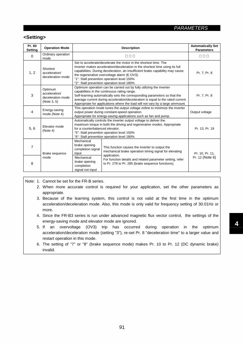
PARAMETERS
91
<Setting>Pr. 60
Setting Operation Mode Description Automatically SetParameters
0 Ordinary operationmode
1, 2Shortestacceleration/deceleration mode
Set to accelerate/decelerate the motor in the shortest time. Theinverter makes acceleration/deceleration in the shortest time using its fullcapabilities. During deceleration, an insufficient brake capability may causethe regenerative overvoltage alarm (E.OV3)."1": Stall prevention operation level 150%"2": Stall prevention operation level 180%
Pr. 7, Pr. 8
3Optimumacceleration/deceleration mode(Note 3, 5)
Optimum operation can be carried out by fully utilizing the invertercapabilities in the continuous rating range.Self-learning automatically sets the corresponding parameters so that theaverage current during acceleration/deceleration is equal to the rated current.Appropriate for applications where the load will not vary by a large ammount.
Pr. 7, Pr. 8
4 Energy-savingmode (Note 4)
This operation mode tunes the output voltage online to minimize the inverteroutput power during constant-speed operation.Appropriate for energy-saving applications such as fan and pump.
Output voltage
5, 6 Elevator mode(Note 4)
Automatically controls the inverter output voltage to deliver themaximum torque in both the driving and regenerative modes. Appropriatefor a counterbalanced elevator."5": Stall prevention operation level 150%"6": Stall prevention operation level 180%
Pr. 13, Pr. 19
7Mechanicalbrake openingcompletion signalinput
8
Brake sequencemode Mechanical
brake openingcompletionsignal not input
This function causes the inverter to output themechanical brake operation timing signal for elevatingapplication.For function details and related parameter setting, referto Pr. 278 to Pr. 285 (brake sequence functions).
Pr. 10, Pr. 11,Pr. 12 (Note 6)
Note: 1. Cannot be set for the FR-B series.2. When more accurate control is required for your application, set the other parameters as
appropriate.3. Because of the learning system, this control is not valid at the first time in the optimum
acceleration/deceleration mode. Also, this mode is only valid for frequency setting of 30.01Hz ormore.
4. Since the FR-B3 series is run under advanced magnetic flux vector control, the settings of theenergy-saving mode and elevator mode are ignored.
5. If an overvoltage (OV3) trip has occurred during operation in the optimumacceleration/deceleration mode (setting "3"), re-set Pr. 8 "deceleration time" to a larger value andrestart operation in this mode.
6. The setting of "7" or "8" (brake sequence mode) makes Pr. 10 to Pr. 12 (DC dynamic brake)invalid.
4
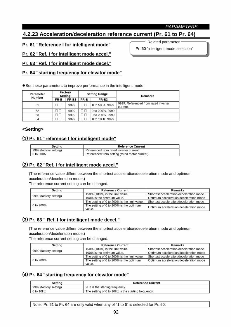
PARAMETERS
92
Pr. 60 "intelligent mode selection"
Related parameter
4.2.23 Acceleration/deceleration reference current (Pr. 61 to Pr. 64)
Pr. 61 "Reference I for intelligent mode"
Pr. 62 "Ref. I for intelligent mode accel."
Pr. 63 "Ref. I for intelligent mode decel."
Pr. 64 "starting frequency for elevator mode"
Set these parameters to improve performance in the intelligent mode.FactorySetting Setting RangeParameter
Number FR-B FR-B3 FR-B FR-B3Remarks
61 9999 0 to 500A, 9999 9999: Referenced from rated invertercurrent.
62 9999 0 to 200%, 999963 9999 0 to 200%, 999964 9999 0 to 10Hz, 9999
<Setting>
(1) Pr. 61 "reference I for intelligent mode"Setting Reference Current
9999 (factory setting) Referenced from rated inverter current0 to 500A Referenced from setting (rated motor current)
(2) Pr. 62 "Ref. I for intelligent mode accel."
(The reference value differs between the shortest acceleration/deceleration mode and optimumacceleration/deceleration mode.)The reference current setting can be changed.
Setting Reference Current Remarks150% (180%) is the limit value. Shortest acceleration/deceleration mode9999 (factory setting) 100% is the optimum value. Optimum acceleration/deceleration modeThe setting of 0 to 200% is the limit value. Shortest acceleration/deceleration mode
0 to 200% The setting of 0 to 200% is the optimumvalue. Optimum acceleration/deceleration mode
(3) Pr. 63 " Ref. I for intelligent mode decel."
(The reference value differs between the shortest acceleration/deceleration mode and optimumacceleration/deceleration mode.)The reference current setting can be changed.
Setting Reference Current Remarks150% (180%) is the limit value. Shortest acceleration/deceleration mode9999 (factory setting) 100% is the optimum value. Optimum acceleration/deceleration modeThe setting of 0 to 200% is the limit value. Shortest acceleration/deceleration mode
0 to 200% The setting of 0 to 200% is the optimumvalue.
Optimum acceleration/deceleration mode
(4) Pr. 64 "starting frequency for elevator mode"Setting Reference Current
9999 (factory setting) 2Hz is the starting frequency.0 to 10Hz The setting of 0 to 10Hz is the starting frequency.
Note: Pr. 61 to Pr. 64 are only valid when any of "1 to 6" is selected for Pr. 60.
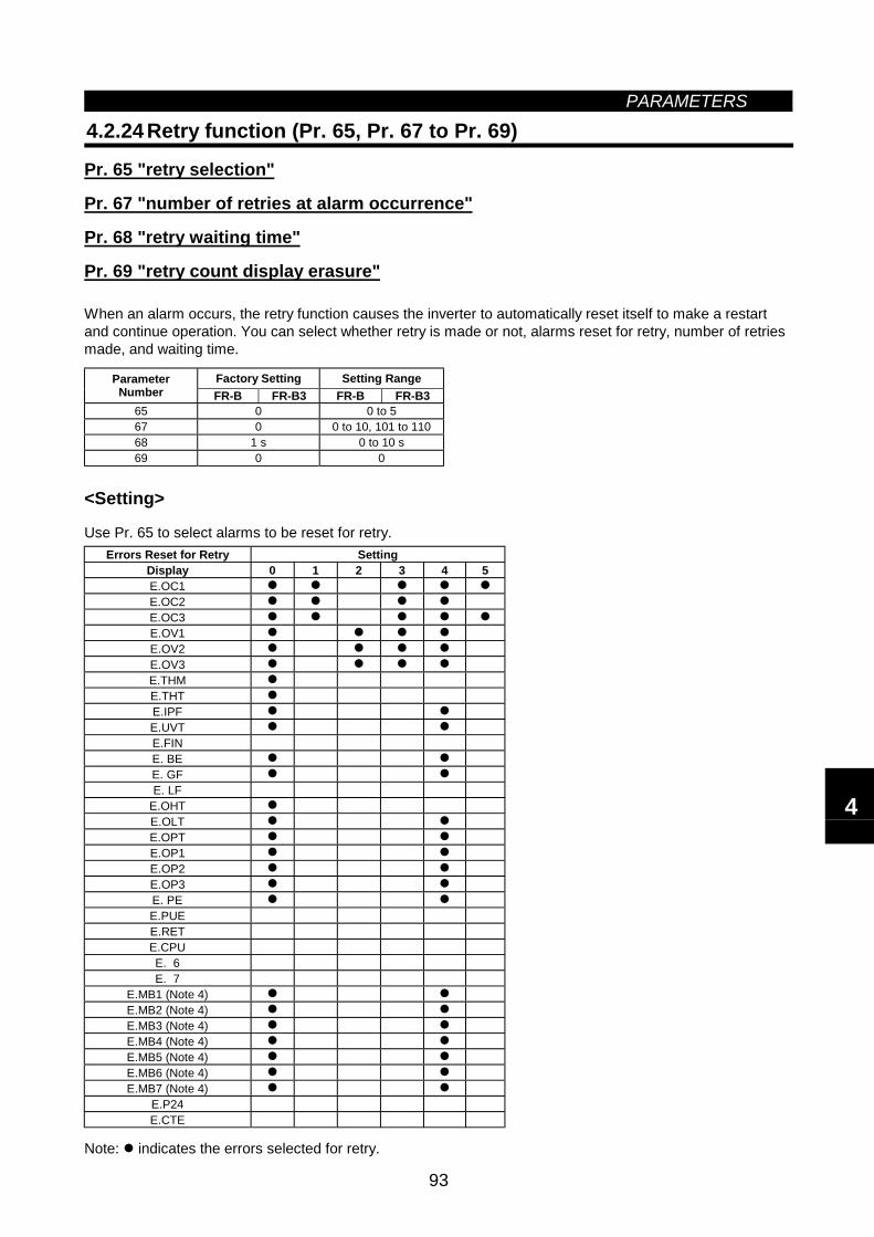
PARAMETERS
93
4.2.24 Retry function (Pr. 65, Pr. 67 to Pr. 69)
Pr. 65 "retry selection"
Pr. 67 "number of retries at alarm occurrence"
Pr. 68 "retry waiting time"
Pr. 69 "retry count display erasure"
When an alarm occurs, the retry function causes the inverter to automatically reset itself to make a restartand continue operation. You can select whether retry is made or not, alarms reset for retry, number of retriesmade, and waiting time.
Factory Setting Setting RangeParameterNumber FR-B FR-B3 FR-B FR-B3
65 0 0 to 567 0 0 to 10, 101 to 11068 1 s 0 to 10 s69 0 0
<Setting>
Use Pr. 65 to select alarms to be reset for retry.Errors Reset for Retry Setting
Display 0 1 2 3 4 5E.OC1E.OC2E.OC3E.OV1E.OV2E.OV3E.THME.THTE.IPFE.UVTE.FINE. BEE. GFE. LF
E.OHTE.OLTE.OPTE.OP1E.OP2E.OP3E. PEE.PUEE.RETE.CPUE. 6E. 7
E.MB1 (Note 4)E.MB2 (Note 4)E.MB3 (Note 4)E.MB4 (Note 4)E.MB5 (Note 4)E.MB6 (Note 4)E.MB7 (Note 4)
E.P24E.CTE
Note: indicates the errors selected for retry.
4
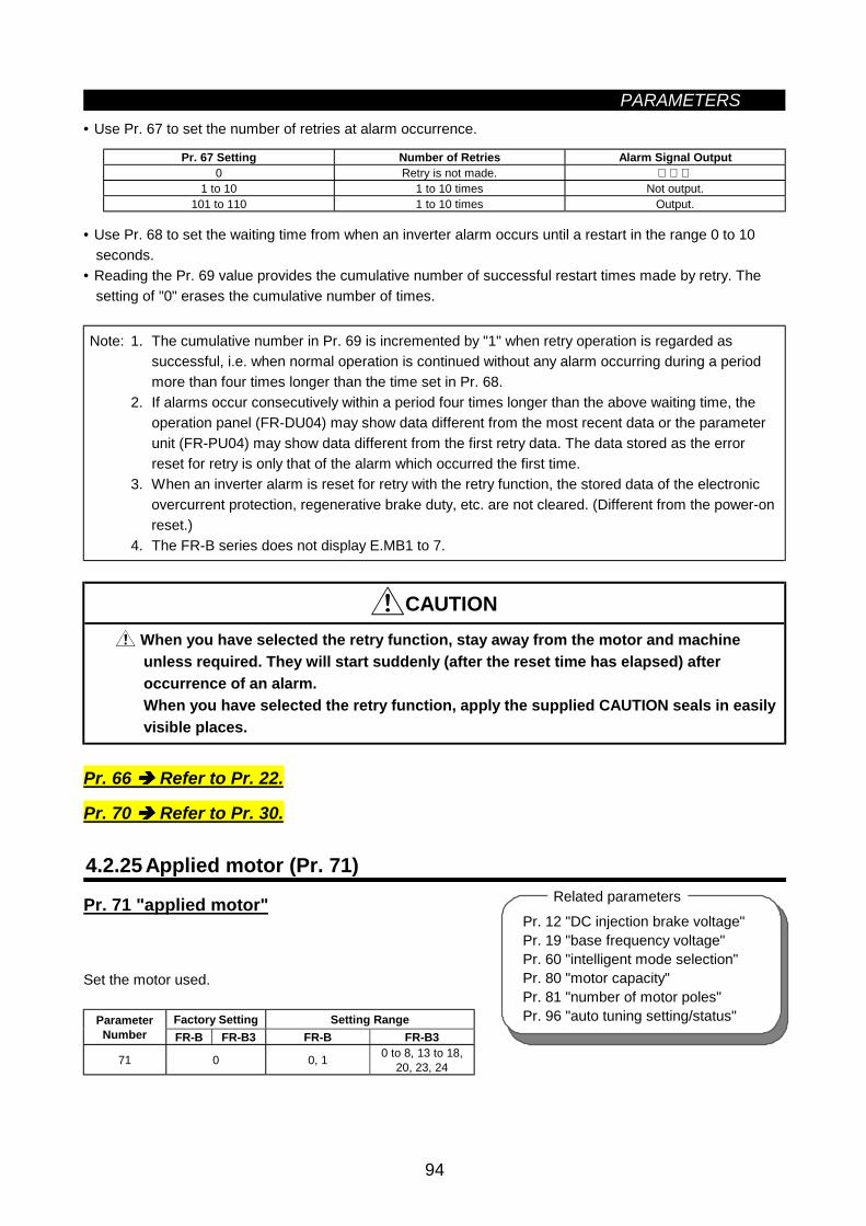
PARAMETERS
94
Pr. 12 "DC injection brake voltage"Pr. 19 "base frequency voltage"Pr. 60 "intelligent mode selection"Pr. 80 "motor capacity"Pr. 81 "number of motor poles"Pr. 96 "auto tuning setting/status"
Related parameters
• Use Pr. 67 to set the number of retries at alarm occurrence.
Pr. 67 Setting Number of Retries Alarm Signal Output0 Retry is not made.
1 to 10 1 to 10 times Not output.101 to 110 1 to 10 times Output.
• Use Pr. 68 to set the waiting time from when an inverter alarm occurs until a restart in the range 0 to 10seconds.
• Reading the Pr. 69 value provides the cumulative number of successful restart times made by retry. Thesetting of "0" erases the cumulative number of times.
Note: 1. The cumulative number in Pr. 69 is incremented by "1" when retry operation is regarded assuccessful, i.e. when normal operation is continued without any alarm occurring during a periodmore than four times longer than the time set in Pr. 68.
2. If alarms occur consecutively within a period four times longer than the above waiting time, theoperation panel (FR-DU04) may show data different from the most recent data or the parameterunit (FR-PU04) may show data different from the first retry data. The data stored as the errorreset for retry is only that of the alarm which occurred the first time.
3. When an inverter alarm is reset for retry with the retry function, the stored data of the electronicovercurrent protection, regenerative brake duty, etc. are not cleared. (Different from the power-onreset.)
4. The FR-B series does not display E.MB1 to 7.
CAUTION When you have selected the retry function, stay away from the motor and machineunless required. They will start suddenly (after the reset time has elapsed) afteroccurrence of an alarm.When you have selected the retry function, apply the supplied CAUTION seals in easilyvisible places.
Pr. 66 Refer to Pr. 22.
Pr. 70 Refer to Pr. 30.
4.2.25 Applied motor (Pr. 71)
Pr. 71 "applied motor"
Set the motor used.
Factory Setting Setting RangeParameterNumber FR-B FR-B3 FR-B FR-B3
71 0 0, 1 0 to 8, 13 to 18,20, 23, 24
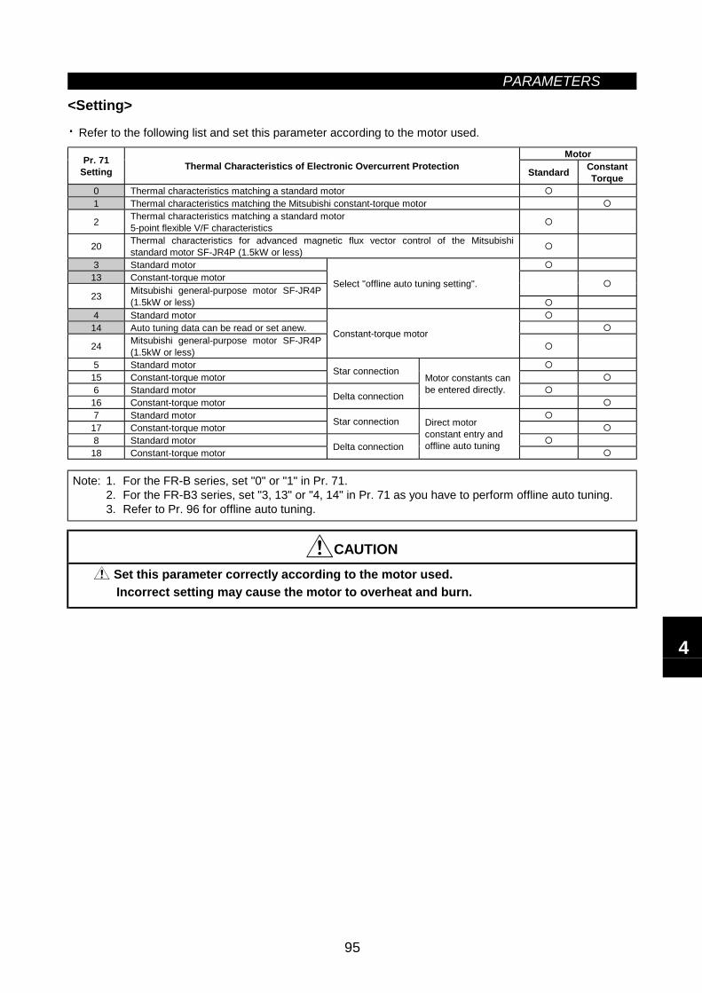
PARAMETERS
95
<Setting>
· Refer to the following list and set this parameter according to the motor used.
MotorPr. 71Setting Thermal Characteristics of Electronic Overcurrent Protection Standard Constant
Torque0 Thermal characteristics matching a standard motor1 Thermal characteristics matching the Mitsubishi constant-torque motor
2 Thermal characteristics matching a standard motor5-point flexible V/F characteristics
20 Thermal characteristics for advanced magnetic flux vector control of the Mitsubishistandard motor SF-JR4P (1.5kW or less)
3 Standard motor13 Constant-torque motor
23 Mitsubishi general-purpose motor SF-JR4P(1.5kW or less)
Select "offline auto tuning setting".
4 Standard motor14 Auto tuning data can be read or set anew.
24 Mitsubishi general-purpose motor SF-JR4P(1.5kW or less)
Constant-torque motor
5 Standard motor15 Constant-torque motor Star connection
6 Standard motor16 Constant-torque motor Delta connection
Motor constants canbe entered directly.
7 Standard motor17 Constant-torque motor Star connection
8 Standard motor18 Constant-torque motor Delta connection
Direct motorconstant entry andoffline auto tuning
Note: 1. For the FR-B series, set "0" or "1" in Pr. 71.2. For the FR-B3 series, set "3, 13" or "4, 14" in Pr. 71 as you have to perform offline auto tuning.3. Refer to Pr. 96 for offline auto tuning.
CAUTION
Set this parameter correctly according to the motor used.Incorrect setting may cause the motor to overheat and burn.
4
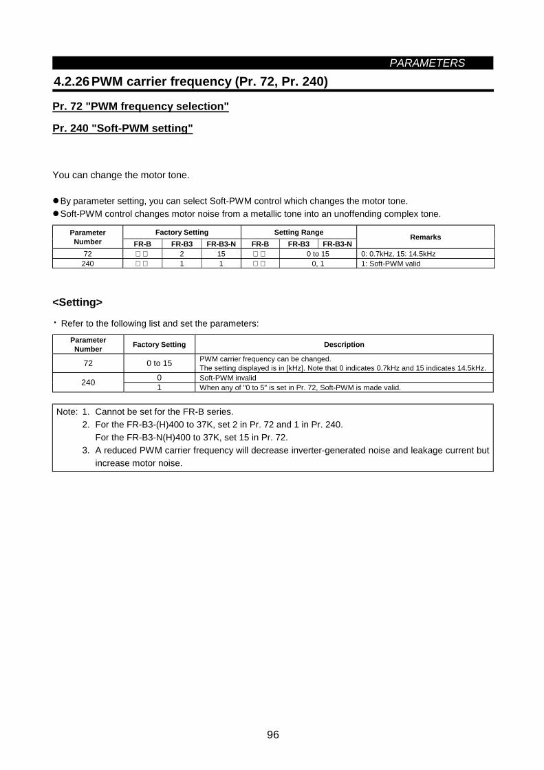
PARAMETERS
96
4.2.26 PWM carrier frequency (Pr. 72, Pr. 240)
Pr. 72 "PWM frequency selection"
Pr. 240 "Soft-PWM setting"
You can change the motor tone.
By parameter setting, you can select Soft-PWM control which changes the motor tone.Soft-PWM control changes motor noise from a metallic tone into an unoffending complex tone.
Factory Setting Setting RangeParameterNumber FR-B FR-B3 FR-B3-N FR-B FR-B3 FR-B3-N
Remarks
72 2 15 0 to 15 0: 0.7kHz, 15: 14.5kHz240 1 1 0, 1 1: Soft-PWM valid
<Setting>
· Refer to the following list and set the parameters:
ParameterNumber Factory Setting Description
72 0 to 15 PWM carrier frequency can be changed.The setting displayed is in [kHz]. Note that 0 indicates 0.7kHz and 15 indicates 14.5kHz.
0 Soft-PWM invalid240 1 When any of "0 to 5" is set in Pr. 72, Soft-PWM is made valid.
Note: 1. Cannot be set for the FR-B series.2. For the FR-B3-(H)400 to 37K, set 2 in Pr. 72 and 1 in Pr. 240.
For the FR-B3-N(H)400 to 37K, set 15 in Pr. 72.3. A reduced PWM carrier frequency will decrease inverter-generated noise and leakage current but
increase motor noise.
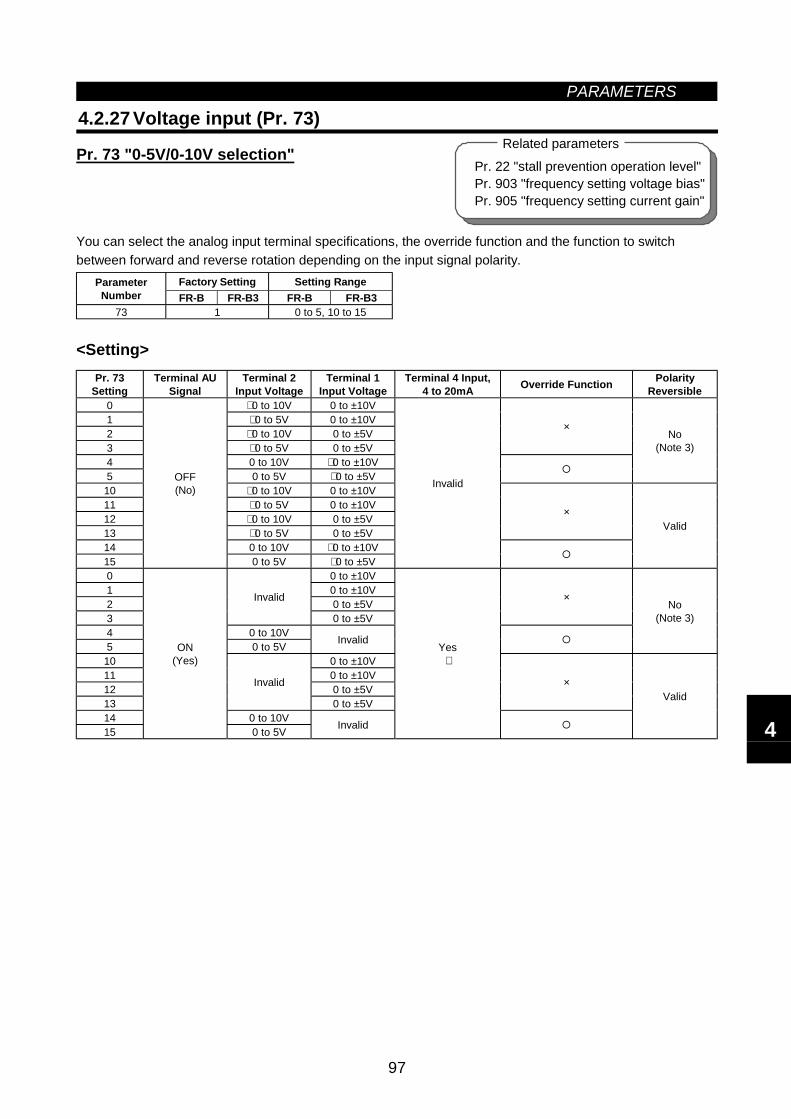
PARAMETERS
97
Pr. 22 "stall prevention operation level"Pr. 903 "frequency setting voltage bias"Pr. 905 "frequency setting current gain"
Related parameters
4.2.27 Voltage input (Pr. 73)
Pr. 73 "0-5V/0-10V selection"
You can select the analog input terminal specifications, the override function and the function to switchbetween forward and reverse rotation depending on the input signal polarity.
Factory Setting Setting RangeParameterNumber FR-B FR-B3 FR-B FR-B3
73 1 0 to 5, 10 to 15
<Setting>Pr. 73
SettingTerminal AU
SignalTerminal 2
Input VoltageTerminal 1
Input VoltageTerminal 4 Input,
4 to 20mA Override Function PolarityReversible
0 ∗ 0 to 10V 0 to ±10V1 ∗ 0 to 5V 0 to ±10V2 ∗ 0 to 10V 0 to ±5V3 ∗ 0 to 5V 0 to ±5V
×
4 0 to 10V ∗ 0 to ±10V5 0 to 5V ∗ 0 to ±5V
No(Note 3)
10 ∗ 0 to 10V 0 to ±10V11 ∗ 0 to 5V 0 to ±10V12 ∗ 0 to 10V 0 to ±5V13 ∗ 0 to 5V 0 to ±5V
×
14 0 to 10V ∗ 0 to ±10V15
OFF(No)
0 to 5V ∗ 0 to ±5V
Invalid
Valid
0 0 to ±10V1 0 to ±10V2 0 to ±5V3
Invalid
0 to ±5V
×
4 0 to 10V5 0 to 5V Invalid
No(Note 3)
10 0 to ±10V11 0 to ±10V12 0 to ±5V13
Invalid
0 to ±5V
×
14 0 to 10V15
ON(Yes)
0 to 5V Invalid
Yes∗
Valid
4
PARAMETERS
98
Note: 1. The value of terminal 1 (frequency setting auxiliary input) is added to the main speed settingsignal of terminal 2 or 4.
2. When override has been selected, terminal 1 or 4 is for the main speed setting and terminal 2 isfor the override signal (50 to 150% at 0-5V or 0-10V).
3. Indicates that a negative-polarity frequency command signal is not accepted.4. To change the maximum output frequency at the input of the maximum frequency command
voltage (current), use the frequency setting voltage (current) gain, Pr. 903 (Pr. 905). At this time,the command voltage (current) need not be input. Also, the acceleration/deceleration time, whichis a slope up/down to the acceleration/deceleration reference frequency, is not affected by thechange in Pr. 73 setting.
5. When the Pr. 22 setting is "9999", the value of terminal 1 is for the stall prevention operation levelsetting.
6. ∗ indicates the main speed setting.
4.2.28 Input filter time constant (Pr. 74)
Pr. 74 "filter time constant"
You can set the input section's internal filter constant of an external voltage or current frequency settingsignal.
Effective for eliminating noise in the frequency setting circuit.Increase the filter time constant if steady operation cannot be performed due to noise. A larger settingresults in lower response. (The time constant can be set between approximately 1ms to 1s. with the settingof 0 to 8. A larger setting results in a larger filter time constant.)
Factory Setting Setting RangeParameterNumber FR-B FR-B3 FR-B FR-B3
74 1 0 to 8
4.2.29 Reset selection/PU disconnection detection/PU stop selection(Pr. 75)
Pr. 75 "reset selection/ disconnected PU detection/PU stop selection"
You can select the reset input acceptance, PU (FR-DU04/FR-PU04) connector disconnection detectionfunction and PU stop function.
Reset selection : You can select the reset function input timing. PU disconnection detection : When detecting that the PU (FR-DU04/FR-PU04) is disconnected from
the inverter for more than 1 second, this function causes the inverter tooutput an alarm code (E.PUE) and come to an alarm stop.
PU stop selection : When an alarm occurs in any operation mode, you can stop the motor from the PU by pressing the [STOP] key.
Factory Setting Setting RangeParameterNumber FR-B FR-B3 FR-B FR-B3
75 14 0 to 3, 14 to 17
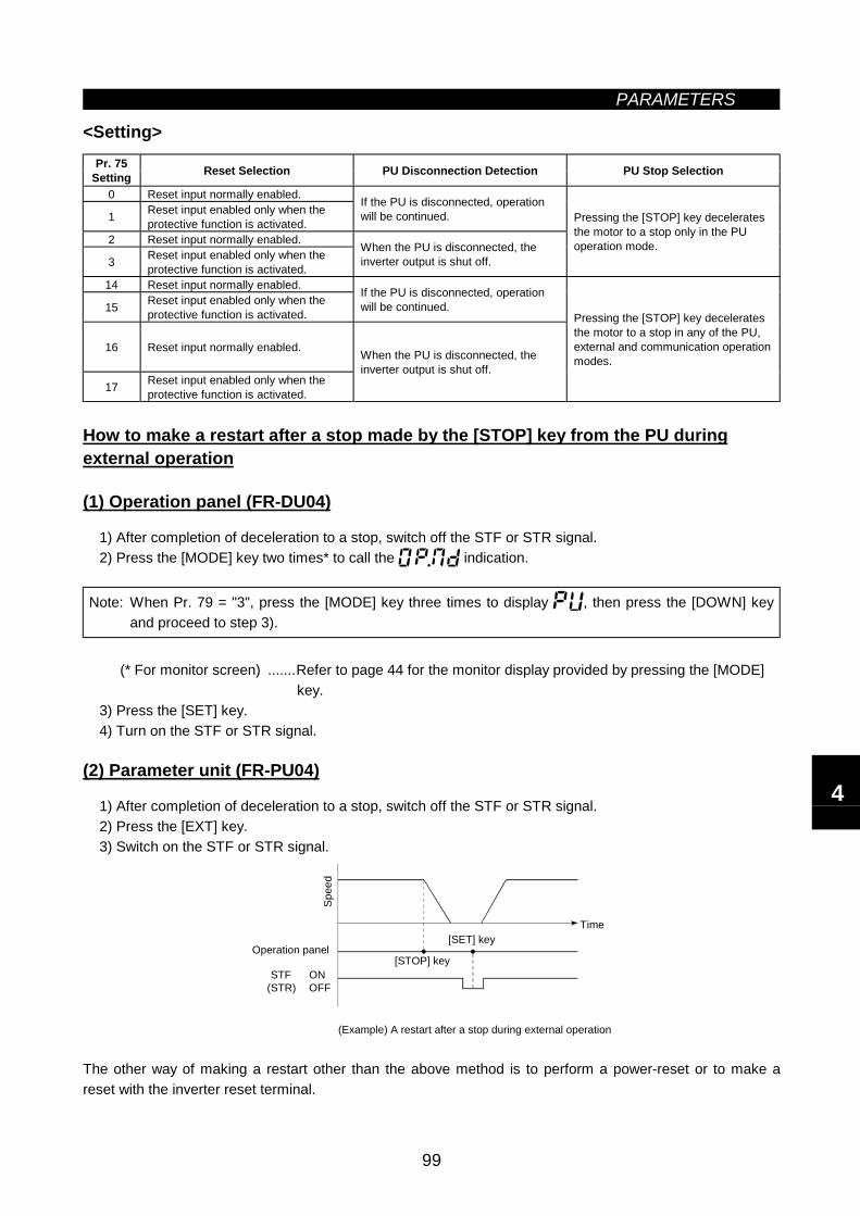
PARAMETERS
99
<Setting>Pr. 75
Setting Reset Selection PU Disconnection Detection PU Stop Selection
0 Reset input normally enabled.
1 Reset input enabled only when theprotective function is activated.
If the PU is disconnected, operationwill be continued.
2 Reset input normally enabled.
3 Reset input enabled only when theprotective function is activated.
When the PU is disconnected, theinverter output is shut off.
Pressing the [STOP] key deceleratesthe motor to a stop only in the PUoperation mode.
14 Reset input normally enabled.
15 Reset input enabled only when theprotective function is activated.
If the PU is disconnected, operationwill be continued.
16 Reset input normally enabled.
17 Reset input enabled only when theprotective function is activated.
When the PU is disconnected, theinverter output is shut off.
Pressing the [STOP] key deceleratesthe motor to a stop in any of the PU,external and communication operationmodes.
How to make a restart after a stop made by the [STOP] key from the PU duringexternal operation
(1) Operation panel (FR-DU04)
1) After completion of deceleration to a stop, switch off the STF or STR signal.2) Press the [MODE] key two times* to call the indication.
Note: When Pr. 79 = "3", press the [MODE] key three times to display , then press the [DOWN] keyand proceed to step 3).
(* For monitor screen) .......Refer to page 44 for the monitor display provided by pressing the [MODE]key.
3) Press the [SET] key.4) Turn on the STF or STR signal.
(2) Parameter unit (FR-PU04)
1) After completion of deceleration to a stop, switch off the STF or STR signal.2) Press the [EXT] key.3) Switch on the STF or STR signal.
(Example) A restart after a stop during external operation
STF ONOFF
Spee
d
Operation panel[SET] key
[STOP] key
Time
(STR)
The other way of making a restart other than the above method is to perform a power-reset or to make areset with the inverter reset terminal.
4
PARAMETERS
100
Note: 1. Entering the reset signal (RES) during operation causes the inverter during a reset to shut off itsoutput, the data of the electronic overcurrent protection to be reset, and the motor to coast.
2. The PU disconnection detection function judges that the PU is disconnected when it is keptdisconnected for more than 1 second. The PU which had been disconnected from before power-on is not judged as an alarm.
3. To resume operation, reset the inverter after confirming that the PU is connected securely.4. When PU disconnection detection is set and the PU is then disconnected during PU jog
operation, the motor decelerates to a stop. The motor will not stop if a PU disconnection alarmoccurs.
5. The Pr. 75 value can be set any time. Also, if parameter (all) clear is executed, this setting will notreturn to the initial value.
6. When the motor is stopped by the PU stop function, PS is displayed but an alarm is not output.When the PU connector is used for RS-485 communication operation, the reset selection and PUstop selection functions are valid but the PU disconnection detection function is invalid.
7. The reset key of the PU is only valid when the protective function is activated, independent of thePr. 75 setting.
CAUTION
Do not reset the inverter with the start signal on.Otherwise, the motor will start instantly after resetting, which may lead to hazardousconditions.
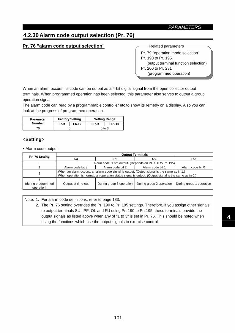
PARAMETERS
101
4.2.30 Alarm code output selection (Pr. 76)
Pr. 76 "alarm code output selection"
When an alarm occurs, its code can be output as a 4-bit digital signal from the open collector outputterminals. When programmed operation has been selected, this parameter also serves to output a groupoperation signal.The alarm code can read by a programmable controller etc to show its remedy on a display. Also you canlook at the progress of programmed operation.
Factory Setting Setting RangeParameterNumber FR-B FR-B3 FR-B FR-B3
76 0 0 to 3
<Setting>
• Alarm code outputOutput TerminalsPr. 76 Setting SU IPF OL FU
0 Alarm code is not output. (Depends on Pr. 190 to Pr. 195).1 Alarm code bit 3 Alarm code bit 2 Alarm code bit 1 Alarm code bit 0
2 When an alarm occurs, an alarm code signal is output. (Output signal is the same as in 1.)When operation is normal, an operation status signal is output. (Output signal is the same as in 0.)
3(during programmed
operation)Output at time-out During group 3 operation During group 2 operation During group 1 operation
Note: 1. For alarm code definitions, refer to page 183.2. The Pr. 76 setting overrides the Pr. 190 to Pr. 195 settings. Therefore, if you assign other signals
to output terminals SU, IPF, OL and FU using Pr. 190 to Pr. 195, these terminals provide theoutput signals as listed above when any of "1 to 3" is set in Pr. 76. This should be noted whenusing the functions which use the output signals to exercise control.
Pr. 79 "operation mode selection"Pr. 190 to Pr. 195 (output terminal function selection)Pr. 200 to Pr. 231 (programmed operation)
Related parameters
4
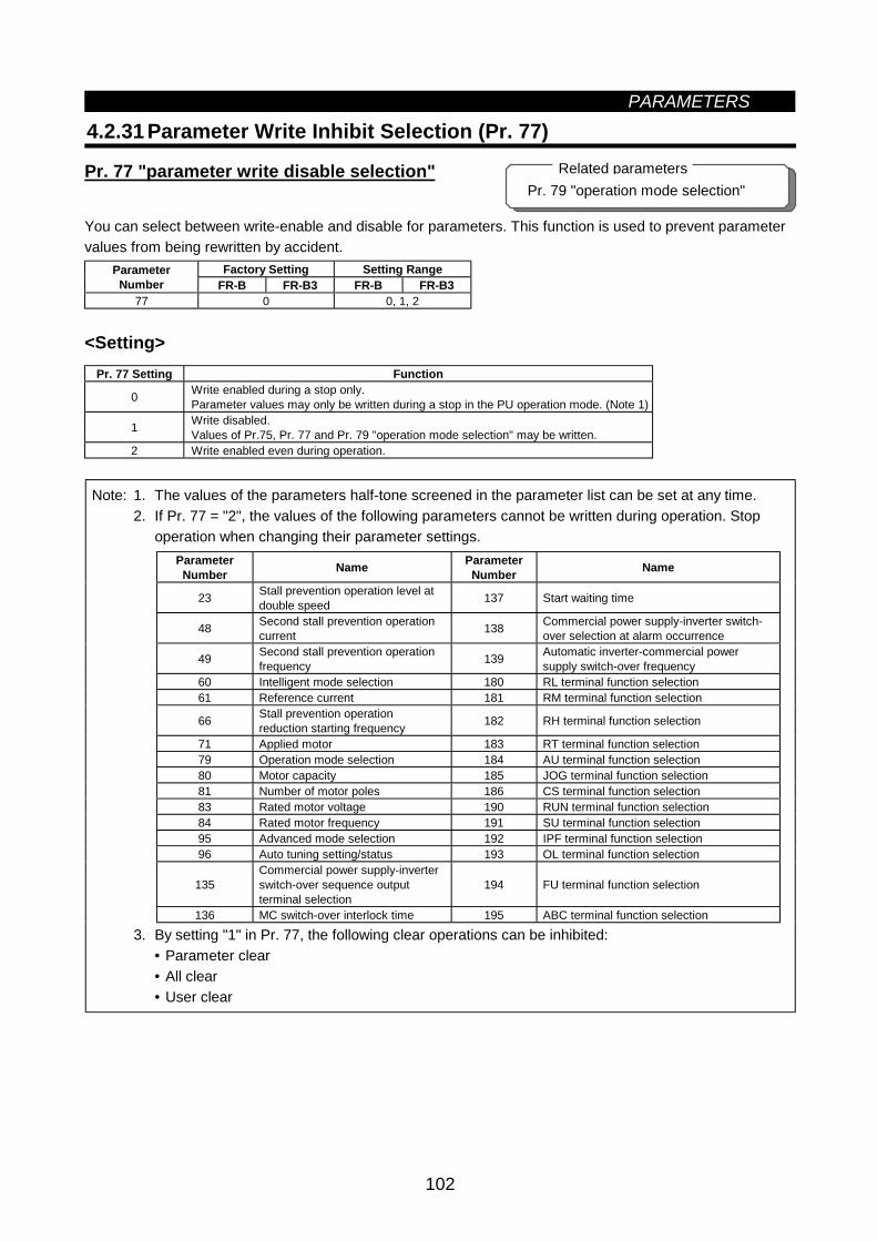
PARAMETERS
102
4.2.31 Parameter Write Inhibit Selection (Pr. 77)
Pr. 77 "parameter write disable selection"
You can select between write-enable and disable for parameters. This function is used to prevent parametervalues from being rewritten by accident.
Factory Setting Setting RangeParameterNumber FR-B FR-B3 FR-B FR-B3
77 0 0, 1, 2
<Setting>Pr. 77 Setting Function
0 Write enabled during a stop only.Parameter values may only be written during a stop in the PU operation mode. (Note 1)
1 Write disabled.Values of Pr.75, Pr. 77 and Pr. 79 "operation mode selection" may be written.
2 Write enabled even during operation.
Note: 1. The values of the parameters half-tone screened in the parameter list can be set at any time.2. If Pr. 77 = "2", the values of the following parameters cannot be written during operation. Stop
operation when changing their parameter settings.ParameterNumber Name Parameter
Number Name
23 Stall prevention operation level atdouble speed 137 Start waiting time
48 Second stall prevention operationcurrent 138 Commercial power supply-inverter switch-
over selection at alarm occurrence
49 Second stall prevention operationfrequency 139 Automatic inverter-commercial power
supply switch-over frequency60 Intelligent mode selection 180 RL terminal function selection61 Reference current 181 RM terminal function selection
66 Stall prevention operationreduction starting frequency 182 RH terminal function selection
71 Applied motor 183 RT terminal function selection79 Operation mode selection 184 AU terminal function selection80 Motor capacity 185 JOG terminal function selection81 Number of motor poles 186 CS terminal function selection83 Rated motor voltage 190 RUN terminal function selection84 Rated motor frequency 191 SU terminal function selection95 Advanced mode selection 192 IPF terminal function selection96 Auto tuning setting/status 193 OL terminal function selection
135Commercial power supply-inverterswitch-over sequence outputterminal selection
194 FU terminal function selection
136 MC switch-over interlock time 195 ABC terminal function selection
3. By setting "1" in Pr. 77, the following clear operations can be inhibited:• Parameter clear• All clear• User clear
Pr. 79 "operation mode selection"Related parameters
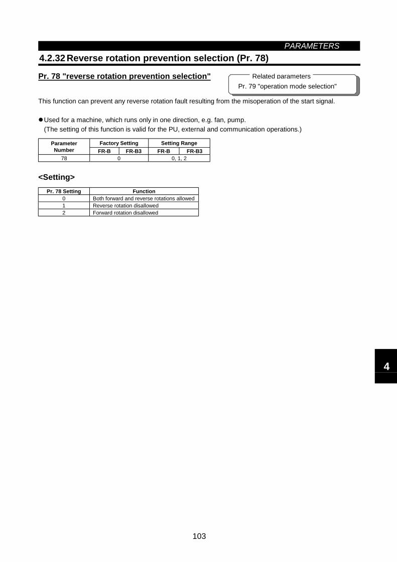
PARAMETERS
103
4.2.32 Reverse rotation prevention selection (Pr. 78)
Pr. 78 "reverse rotation prevention selection"
This function can prevent any reverse rotation fault resulting from the misoperation of the start signal.
Used for a machine, which runs only in one direction, e.g. fan, pump.(The setting of this function is valid for the PU, external and communication operations.)
Factory Setting Setting RangeParameterNumber FR-B FR-B3 FR-B FR-B3
78 0 0, 1, 2
<Setting>Pr. 78 Setting Function
0 Both forward and reverse rotations allowed1 Reverse rotation disallowed2 Forward rotation disallowed
Pr. 79 "operation mode selection"Related parameters
4
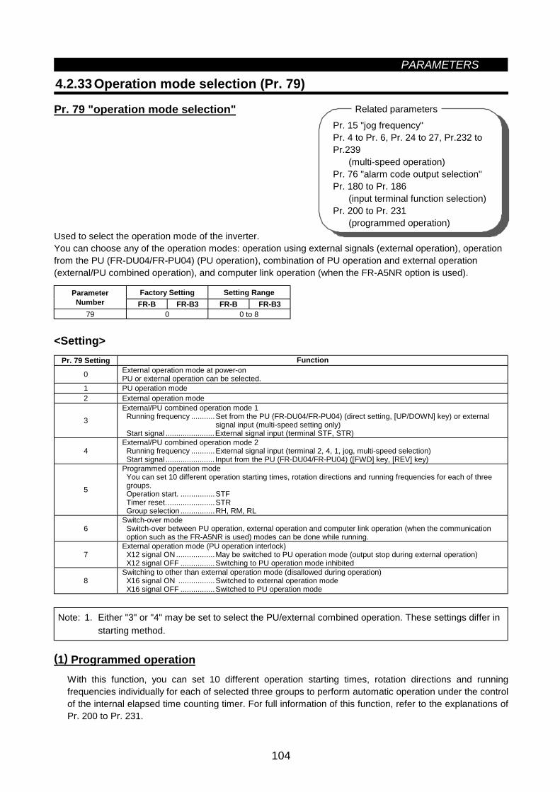
PARAMETERS
104
4.2.33 Operation mode selection (Pr. 79)
Pr. 79 "operation mode selection"
Used to select the operation mode of the inverter.You can choose any of the operation modes: operation using external signals (external operation), operationfrom the PU (FR-DU04/FR-PU04) (PU operation), combination of PU operation and external operation(external/PU combined operation), and computer link operation (when the FR-A5NR option is used).
Factory Setting Setting RangeParameterNumber FR-B FR-B3 FR-B FR-B3
79 0 0 to 8
<Setting>Pr. 79 Setting Function
0 External operation mode at power-onPU or external operation can be selected.
1 PU operation mode2 External operation mode
3External/PU combined operation mode 1 Running frequency ...........Set from the PU (FR-DU04/FR-PU04) (direct setting, [UP/DOWN] key) or external
signal input (multi-speed setting only) Start signal .......................External signal input (terminal STF, STR)
4External/PU combined operation mode 2 Running frequency ...........External signal input (terminal 2, 4, 1, jog, multi-speed selection) Start signal ....................... Input from the PU (FR-DU04/FR-PU04) ([FWD] key, [REV] key)
5
Programmed operation mode You can set 10 different operation starting times, rotation directions and running frequencies for each of three groups. Operation start. ................STF Timer reset.......................STR Group selection ................RH, RM, RL
6Switch-over mode Switch-over between PU operation, external operation and computer link operation (when the communication option such as the FR-A5NR is used) modes can be done while running.
7External operation mode (PU operation interlock) X12 signal ON ..................May be switched to PU operation mode (output stop during external operation) X12 signal OFF ................Switching to PU operation mode inhibited
8Switching to other than external operation mode (disallowed during operation) X16 signal ON .................Switched to external operation mode X16 signal OFF ................Switched to PU operation mode
Note: 1. Either "3" or "4" may be set to select the PU/external combined operation. These settings differ instarting method.
(1) Programmed operationWith this function, you can set 10 different operation starting times, rotation directions and runningfrequencies individually for each of selected three groups to perform automatic operation under the controlof the internal elapsed time counting timer. For full information of this function, refer to the explanations ofPr. 200 to Pr. 231.
Pr. 15 "jog frequency"Pr. 4 to Pr. 6, Pr. 24 to 27, Pr.232 toPr.239 "multi-speed operation"Pr. 76 "alarm code output selection"Pr. 180 to Pr. 186 (input terminal function selection)Pr. 200 to Pr. 231 "programmed operation"
Pr. 15 "jog frequency"Pr. 4 to Pr. 6, Pr. 24 to 27, Pr.232 toPr.239 (multi-speed operation)Pr. 76 "alarm code output selection"Pr. 180 to Pr. 186 (input terminal function selection)Pr. 200 to Pr. 231 (programmed operation)
Related parameters
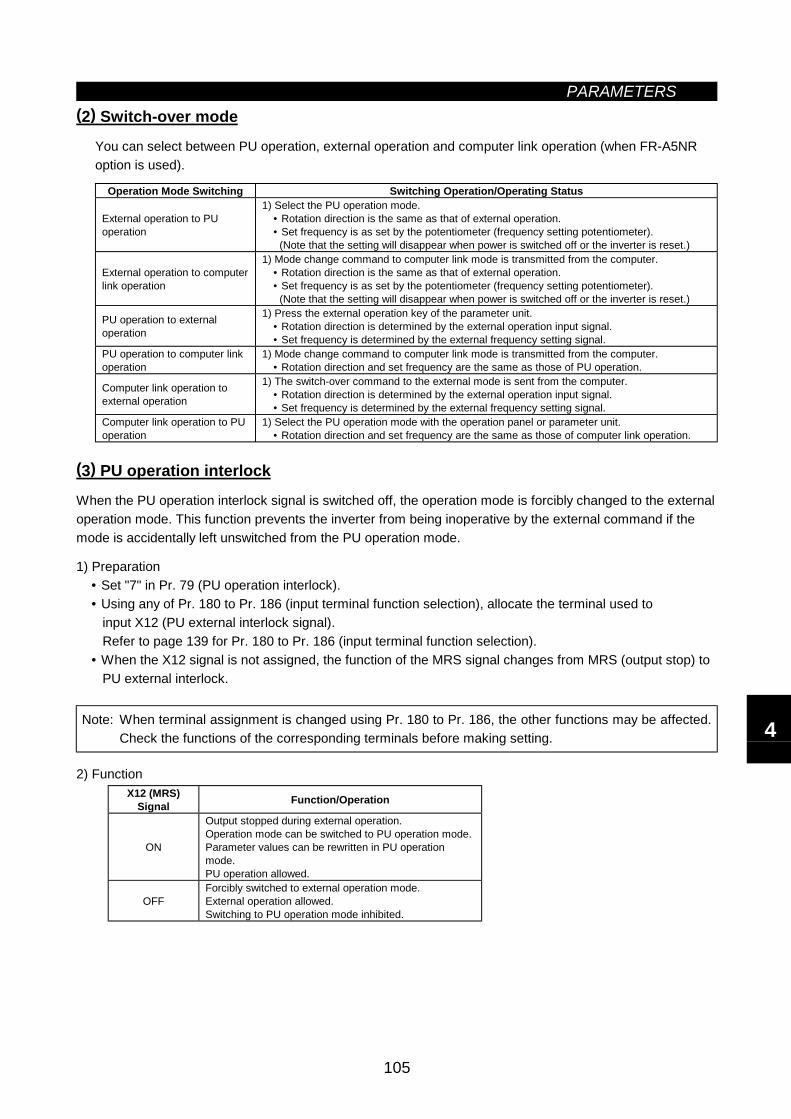
PARAMETERS
105
(2) Switch-over mode
You can select between PU operation, external operation and computer link operation (when FR-A5NRoption is used).
Operation Mode Switching Switching Operation/Operating Status
External operation to PUoperation
1) Select the PU operation mode.• Rotation direction is the same as that of external operation.• Set frequency is as set by the potentiometer (frequency setting potentiometer). (Note that the setting will disappear when power is switched off or the inverter is reset.)
External operation to computerlink operation
1) Mode change command to computer link mode is transmitted from the computer.• Rotation direction is the same as that of external operation.• Set frequency is as set by the potentiometer (frequency setting potentiometer). (Note that the setting will disappear when power is switched off or the inverter is reset.)
PU operation to externaloperation
1) Press the external operation key of the parameter unit.• Rotation direction is determined by the external operation input signal.• Set frequency is determined by the external frequency setting signal.
PU operation to computer linkoperation
1) Mode change command to computer link mode is transmitted from the computer.• Rotation direction and set frequency are the same as those of PU operation.
Computer link operation toexternal operation
1) The switch-over command to the external mode is sent from the computer.• Rotation direction is determined by the external operation input signal.• Set frequency is determined by the external frequency setting signal.
Computer link operation to PUoperation
1) Select the PU operation mode with the operation panel or parameter unit.• Rotation direction and set frequency are the same as those of computer link operation.
(3) PU operation interlock
When the PU operation interlock signal is switched off, the operation mode is forcibly changed to the externaloperation mode. This function prevents the inverter from being inoperative by the external command if themode is accidentally left unswitched from the PU operation mode.
1) Preparation• Set "7" in Pr. 79 (PU operation interlock).• Using any of Pr. 180 to Pr. 186 (input terminal function selection), allocate the terminal used to input X12 (PU external interlock signal). Refer to page 139 for Pr. 180 to Pr. 186 (input terminal function selection).• When the X12 signal is not assigned, the function of the MRS signal changes from MRS (output stop) to PU external interlock.
Note: When terminal assignment is changed using Pr. 180 to Pr. 186, the other functions may be affected.Check the functions of the corresponding terminals before making setting.
2) FunctionX12 (MRS)
Signal Function/Operation
ON
Output stopped during external operation.Operation mode can be switched to PU operation mode.Parameter values can be rewritten in PU operationmode.PU operation allowed.
OFFForcibly switched to external operation mode.External operation allowed.Switching to PU operation mode inhibited.
4
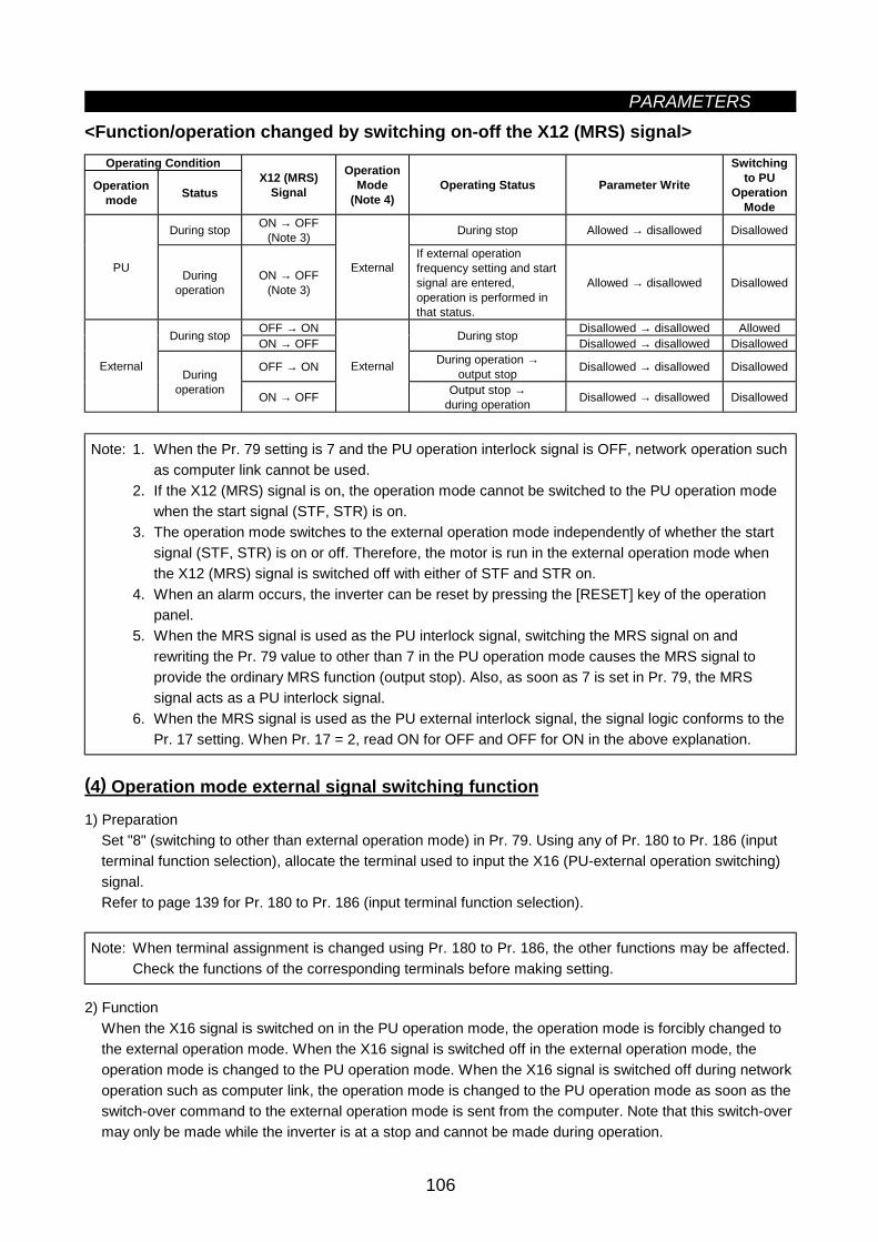
PARAMETERS
106
<Function/operation changed by switching on-off the X12 (MRS) signal>Operating Condition
Operationmode Status
X12 (MRS)Signal
OperationMode
(Note 4)Operating Status Parameter Write
Switchingto PU
OperationMode
During stop ON → OFF(Note 3) During stop Allowed → disallowed Disallowed
PU Duringoperation
ON → OFF(Note 3)
ExternalIf external operationfrequency setting and startsignal are entered,operation is performed inthat status.
Allowed → disallowed Disallowed
OFF → ON Disallowed → disallowed AllowedDuring stop ON → OFF During stop Disallowed → disallowed Disallowed
OFF → ON During operation →output stop Disallowed → disallowed DisallowedExternal
Duringoperation ON → OFF
External
Output stop →during operation Disallowed → disallowed Disallowed
Note: 1. When the Pr. 79 setting is 7 and the PU operation interlock signal is OFF, network operation suchas computer link cannot be used.
2. If the X12 (MRS) signal is on, the operation mode cannot be switched to the PU operation modewhen the start signal (STF, STR) is on.
3. The operation mode switches to the external operation mode independently of whether the startsignal (STF, STR) is on or off. Therefore, the motor is run in the external operation mode whenthe X12 (MRS) signal is switched off with either of STF and STR on.
4. When an alarm occurs, the inverter can be reset by pressing the [RESET] key of the operationpanel.
5. When the MRS signal is used as the PU interlock signal, switching the MRS signal on andrewriting the Pr. 79 value to other than 7 in the PU operation mode causes the MRS signal toprovide the ordinary MRS function (output stop). Also, as soon as 7 is set in Pr. 79, the MRSsignal acts as a PU interlock signal.
6. When the MRS signal is used as the PU external interlock signal, the signal logic conforms to thePr. 17 setting. When Pr. 17 = 2, read ON for OFF and OFF for ON in the above explanation.
(4) Operation mode external signal switching function
1) PreparationSet "8" (switching to other than external operation mode) in Pr. 79. Using any of Pr. 180 to Pr. 186 (inputterminal function selection), allocate the terminal used to input the X16 (PU-external operation switching)signal.Refer to page 139 for Pr. 180 to Pr. 186 (input terminal function selection).
Note: When terminal assignment is changed using Pr. 180 to Pr. 186, the other functions may be affected.Check the functions of the corresponding terminals before making setting.
2) FunctionWhen the X16 signal is switched on in the PU operation mode, the operation mode is forcibly changed tothe external operation mode. When the X16 signal is switched off in the external operation mode, theoperation mode is changed to the PU operation mode. When the X16 signal is switched off during networkoperation such as computer link, the operation mode is changed to the PU operation mode as soon as theswitch-over command to the external operation mode is sent from the computer. Note that this switch-overmay only be made while the inverter is at a stop and cannot be made during operation.
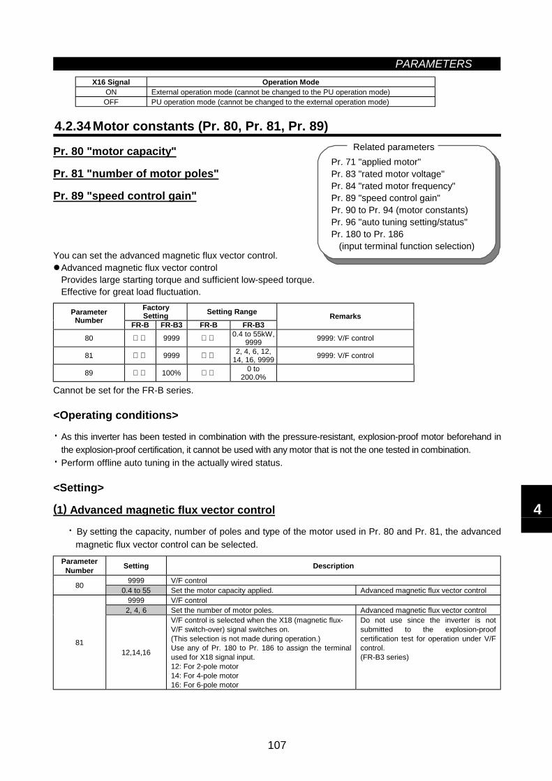
PARAMETERS
107
Pr. 71 "applied motor"Pr. 83 "rated motor voltage"Pr. 84 "rated motor frequency"Pr. 89 "speed control gain"Pr. 90 to Pr. 94 (motor constants)Pr. 96 "auto tuning setting/status"Pr. 180 to Pr. 186 (input terminal function selection)
Related parameters
X16 Signal Operation ModeON External operation mode (cannot be changed to the PU operation mode)OFF PU operation mode (cannot be changed to the external operation mode)
4.2.34 Motor constants (Pr. 80, Pr. 81, Pr. 89)
Pr. 80 "motor capacity"
Pr. 81 "number of motor poles"
Pr. 89 "speed control gain"
You can set the advanced magnetic flux vector control.Advanced magnetic flux vector controlProvides large starting torque and sufficient low-speed torque.Effective for great load fluctuation.
FactorySetting Setting RangeParameter
Number FR-B FR-B3 FR-B FR-B3Remarks
80 9999 0.4 to 55kW,9999 9999: V/F control
81 9999 2, 4, 6, 12,14, 16, 9999 9999: V/F control
89 100% 0 to200.0%
Cannot be set for the FR-B series.
<Operating conditions>
· As this inverter has been tested in combination with the pressure-resistant, explosion-proof motor beforehand inthe explosion-proof certification, it cannot be used with any motor that is not the one tested in combination.
· Perform offline auto tuning in the actually wired status.
<Setting>
(1) Advanced magnetic flux vector control
· By setting the capacity, number of poles and type of the motor used in Pr. 80 and Pr. 81, the advancedmagnetic flux vector control can be selected.
ParameterNumber Setting Description
9999 V/F control80 0.4 to 55 Set the motor capacity applied. Advanced magnetic flux vector control9999 V/F control
2, 4, 6 Set the number of motor poles. Advanced magnetic flux vector control
8112,14,16
V/F control is selected when the X18 (magnetic flux-V/F switch-over) signal switches on.(This selection is not made during operation.)Use any of Pr. 180 to Pr. 186 to assign the terminalused for X18 signal input.12: For 2-pole motor14: For 4-pole motor16: For 6-pole motor
Do not use since the inverter is notsubmitted to the explosion-proofcertification test for operation under V/Fcontrol.(FR-B3 series)
4

PARAMETERS
108
Pr. 7 "acceleration time"Pr. 9 "electronic overcurrent protection"Pr. 71 "applied motor"Pr. 80 "motor capacity"Pr. 81 "number of motor poles"Pr. 156 "stall prevention operation selection"
Related parameters
Note: 1. Speed fluctuation is slightly greater than in the V/F control. (Advanced magnetic flux vectorcontrol may not be suitable for machines which attach importance to little speed fluctuationat low speed, e.g. grinders, lapping machines.)
2. When the surge voltage suppression filter (FR-ASF-H) is used between the inverter andmotor, output torque may reduce.
3. When the terminal functions are changed using Pr. 180 to Pr. 186, the other functions maybe affected. Confirm the functions of the corresponding terminals before making setting.
· For adjustment of motor speed fluctuation due to load variationPr. 89 can be used to adjust motor speed fluctuation when the load varies
Speed
Load
torq
ue
4.2.35 Offline auto tuning function (Pr. 82 to Pr. 84, Pr. 90 to Pr. 94, Pr. 96)
Pr. 82 "motor exciting current"
Pr. 83 "rated motor voltage"
Pr. 84 "rated motor frequency"
Pr. 90 "motor constant (R1)"
Pr. 91 "motor constant (R2)"
Pr. 92 "motor constant (L1)"
Pr. 93 "motor constant (L2)"
Pr. 94 "motor constant (X)"
Pr. 96 "auto tuning setting/status"
When you use the advanced magnetic flux vector control, you can perform the offline auto tuning operation tocalculate motor constants automatically.
Cannot be set for the FR-B series.Offline auto tuning is made valid only when other values than "9999" are set in Pr. 80 and Pr. 81 to selectthe advanced magnetic flux vector control.Offline auto tuningAutomatically measures the motor constants used for advanced magnetic flux vector control.· Offline auto tuning can be performed with the load connected. (As the load is smaller, tuning accuracy is
higher. Tuning accuracy does not change if inertia is large.)· For the offline auto tuning, you can select either the motor non-rotation mode or rotation mode.· You can read, write and copy the motor constants tuned by the offline auto tuning.· The offline auto tuning status can be monitored with the PU (FR-DU04/FR-PU04).
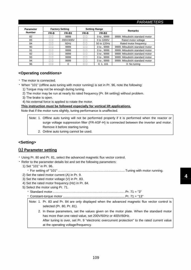
PARAMETERS
109
Factory Setting Setting RangeParameterNumber FR-B FR-B3 FR-B FR-B3
Remarks
82 9999 0 to , 9999 9999: Mitsubishi standard motor83 200V/400V 0 to 1000V Rated motor voltage84 60Hz 50 to 120Hz Rated motor frequency90 9999 0 to , 9999 9999: Mitsubishi standard motor91 9999 0 to , 9999 9999: Mitsubishi standard motor92 9999 0 to , 9999 9999: Mitsubishi standard motor93 9999 0 to , 9999 9999: Mitsubishi standard motor94 9999 0 to , 9999 9999: Mitsubishi standard motor96 0 0, 1, 101 0: No tuning
<Operating conditions>
· The motor is connected.· When "101" (offline auto tuning with motor running) is set in Pr. 96, note the following:
1) Torque may not be enough during tuning.2) The motor may be run at nearly its rated frequency (Pr. 84 setting) without problem.3) The brake is open.4) No external force is applied to rotate the motor.
This instruction must be followed especially for vertical lift applications.Note that if the motor runs slightly, tuning performance is unaffected.
Note: 1. Offline auto tuning will not be performed properly if it is performed when the reactor orsurge voltage suppression filter (FR-ASF-H) is connected between the inverter and motor.Remove it before starting tuning.
2. Online auto tuning cannot be used.
<Setting>
(1) Parameter setting
· Using Pr. 80 and Pr. 81, select the advanced magnetic flux vector control.· Refer to the parameter details list and set the following parameters:
1) Set "101" in Pr. 96.· For setting of "101" ............................................................................Tuning with motor running.
2) Set the rated motor current (A) in Pr. 9.3) Set the rated motor voltage (V) in Pr. 83.4) Set the rated motor frequency (Hz) in Pr. 84.5) Select the motor using Pr. 71.
· Standard motor..................................................................................Pr. 71 = "3"· Constant-torque motor ......................................................................Pr. 71 = "13"
Note: 1. Pr. 83 and Pr. 84 are only displayed when the advanced magnetic flux vector control isselected (Pr. 80, Pr. 81).
2. In these parameters, set the values given on the motor plate. When the standard motorhas more than one rated value, set 200V/60Hz or 400V/60Hz.After tuning is over, set Pr. 9 "electronic overcurrent protection" to the rated current valueat the operating voltage/frequency.
4
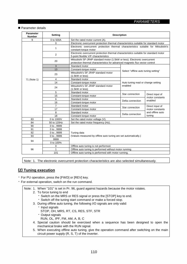
PARAMETERS
110
Parameter detailsParameterNumber Setting Description
9 0 to 500A Set the rated motor current (A).0 Electronic overcurrent protection thermal characteristics suitable for standard motor
1 Electronic overcurrent protection thermal characteristics suitable for Mitsubishi'sconstant-torque motor
2 Electronic overcurrent protection thermal characteristics suitable for standard motor5-point flexible V/F characteristics
20 Mitsubishi SF-JR4P standard motor (1.5kW or less). Electronic overcurrentprotection thermal characteristics for advanced magnetic flux vector control
3 Standard motor13 Constant-torque motor
23 Mitsubishi's SF-JR4P standard motor(1.5kW or less)
Select "offline auto tuning setting"
4 Standard motor14 Constant-torque motor
24 Mitsubishi's SF-JR4P standard motor(1.5kW or less)
Auto tuning read or change settingenabled
5 Standard motor15 Constant-torque motor Star connection
6 Standard motor16 Constant-torque motor Delta connection
Direct input ofmotor constantsenabled
7 Standard motor17 Constant-torque motor Star connection
8 Standard motor
71 (Note 1)
18 Constant-torque motor Delta connection
Direct input ofmotor constantsand offline autotuning
83 0 to 1000V Set the rated motor voltage (V).84 50 to 120Hz Set the rated motor frequency (Hz).90 0 to , 999991 0 to , 999992 0 to , 999993 0 to , 9999
999994 0 to 100%
Tuning data(Values measured by offline auto tuning are set automatically.)
0 Offline auto tuning is not performed.1 Offline auto tuning is performed without motor running.96
101 Offline auto tuning is performed with motor running.
Note: 1. The electronic overcurrent protection characteristics are also selected simultaneously.
(2) Tuning execution
· For PU operation, press the [FWD] or [REV] key.· For external operation, switch on the run command.
Note: 1. When "101" is set in Pr. 96, guard against hazards because the motor rotates.2. To force tuning to end
· Switch on the MRS or RES signal or press the [STOP] key to end.· Switch off the tuning start command or make a forced stop.
3. During offline auto tuning, the following I/O signals are only valid:· Input signals
STOP, OH, MRS, RT, CS, RES, STF, STR· Output signals
RUN, OL, IPF, FM, AM, A, B, C4. Special caution should be exercised when a sequence has been designed to open the
mechanical brake with the RUN signal.5. When executing offline auto tuning, give the operation command after switching on the main
circuit power supply (R, S, T) of the inverter.
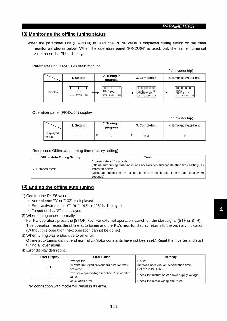
PARAMETERS
111
(3) Monitoring the offline tuning status
When the parameter unit (FR-PU04) is used, the Pr. 96 value is displayed during tuning on the mainmonitor as shown below. When the operation panel (FR-DU04) is used, only the same numericalvalue as on the PU is displayed:
· Parameter unit (FR-PU04) main monitor (For inverter trip)
1. Setting 2. Tuning inprogress 3. Completion 4. Error-activated end
DisplaySTOP PU101
FWD PU102
STF
TUNE
STOP PU
103STF
TUNECOMPLETION
STOP PU9
STF
TUNEERROR
· Operation panel (FR-DU04) display (For inverter trip)
1. Setting 2. Tuning inprogress 3. Completion 4. Error-activated end
Displayedvalue 101 102 103 9
· Reference: Offline auto tuning time (factory setting)Offline Auto Tuning Setting Time
2: Rotation mode
Approximately 40 seconds(Offline auto tuning time varies with acceleration and deceleration time settings asindicated below:Offline auto tuning time = acceleration time + deceleration time + approximately 30seconds)
(4) Ending the offline auto tuning
1) Confirm the Pr. 96 value.· Normal end: "3" or "103" is displayed.· Error-activated end: "9", "91", "92" or "93" is displayed.· Forced end ... "8" is displayed.
2) When tuning ended normally.For PU operation, press the [STOP] key. For external operation, switch off the start signal (STF or STR).This operation resets the offline auto tuning and the PU's monitor display returns to the ordinary indication.(Without this operation, next operation cannot be done.)
3) When tuning was ended due to an error.Offline auto tuning did not end normally. (Motor constants have not been set.) Reset the inverter and starttuning all over again.
4) Error display definitions.
Error Display Error Cause Remedy9 Inverter trip Re-set.
91 Current limit (stall prevention) function wasactivated.
Increase acceleration/deceleration time.Set "1" in Pr. 156.
92 Inverter output voltage reached 75% of ratedvalue. Check for fluctuation of power supply voltage.
93 Calculation error Check the motor wiring and re-set.
No connection with motor will result in 93 error.
4
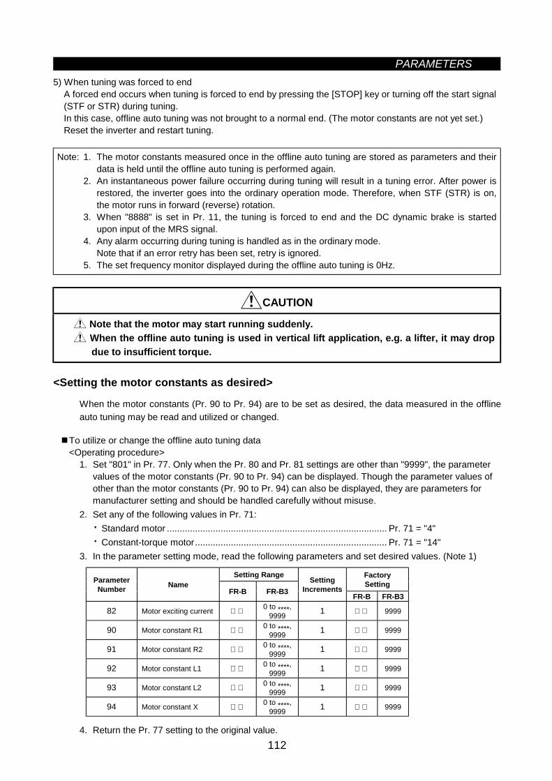
PARAMETERS
112
5) When tuning was forced to endA forced end occurs when tuning is forced to end by pressing the [STOP] key or turning off the start signal(STF or STR) during tuning.In this case, offline auto tuning was not brought to a normal end. (The motor constants are not yet set.)Reset the inverter and restart tuning.
Note: 1. The motor constants measured once in the offline auto tuning are stored as parameters and theirdata is held until the offline auto tuning is performed again.
2. An instantaneous power failure occurring during tuning will result in a tuning error. After power isrestored, the inverter goes into the ordinary operation mode. Therefore, when STF (STR) is on,the motor runs in forward (reverse) rotation.
3. When "8888" is set in Pr. 11, the tuning is forced to end and the DC dynamic brake is startedupon input of the MRS signal.
4. Any alarm occurring during tuning is handled as in the ordinary mode.Note that if an error retry has been set, retry is ignored.
5. The set frequency monitor displayed during the offline auto tuning is 0Hz.
CAUTION
Note that the motor may start running suddenly. When the offline auto tuning is used in vertical lift application, e.g. a lifter, it may dropdue to insufficient torque.
<Setting the motor constants as desired>
When the motor constants (Pr. 90 to Pr. 94) are to be set as desired, the data measured in the offlineauto tuning may be read and utilized or changed.
To utilize or change the offline auto tuning data<Operating procedure>
1. Set "801" in Pr. 77. Only when the Pr. 80 and Pr. 81 settings are other than "9999", the parametervalues of the motor constants (Pr. 90 to Pr. 94) can be displayed. Though the parameter values ofother than the motor constants (Pr. 90 to Pr. 94) can also be displayed, they are parameters formanufacturer setting and should be handled carefully without misuse.
2. Set any of the following values in Pr. 71:· Standard motor ...................................................................................... Pr. 71 = "4"· Constant-torque motor........................................................................... Pr. 71 = "14"
3. In the parameter setting mode, read the following parameters and set desired values. (Note 1)
Setting Range FactorySettingParameter
Number NameFR-B FR-B3
SettingIncrements
FR-B FR-B3
82 Motor exciting current 0 to ****,9999 1 9999
90 Motor constant R1 0 to ****,9999 1 9999
91 Motor constant R2 0 to ****,9999 1 9999
92 Motor constant L1 0 to ****,9999 1 9999
93 Motor constant L2 0 to ****,9999 1 9999
94 Motor constant X 0 to ****,9999 1 9999
4. Return the Pr. 77 setting to the original value.
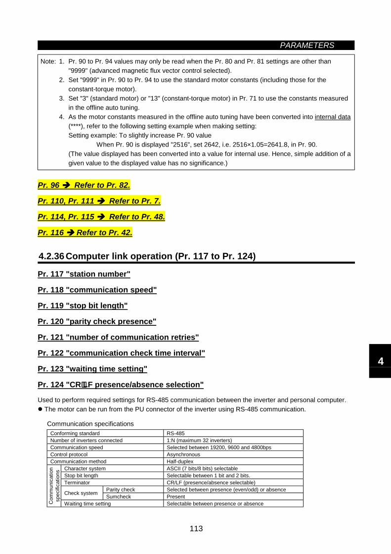
PARAMETERS
113
Note: 1. Pr. 90 to Pr. 94 values may only be read when the Pr. 80 and Pr. 81 settings are other than"9999" (advanced magnetic flux vector control selected).
2. Set "9999" in Pr. 90 to Pr. 94 to use the standard motor constants (including those for theconstant-torque motor).
3. Set "3" (standard motor) or "13" (constant-torque motor) in Pr. 71 to use the constants measuredin the offline auto tuning.
4. As the motor constants measured in the offline auto tuning have been converted into internal data(****), refer to the following setting example when making setting:Setting example: To slightly increase Pr. 90 value
When Pr. 90 is displayed "2516", set 2642, i.e. 2516×1.05=2641.8, in Pr. 90.(The value displayed has been converted into a value for internal use. Hence, simple addition of agiven value to the displayed value has no significance.)
Pr. 96 Refer to Pr. 82.
Pr. 110, Pr. 111 Refer to Pr. 7.
Pr. 114, Pr. 115 Refer to Pr. 48.
Pr. 116 Refer to Pr. 42.
4.2.36 Computer link operation (Pr. 117 to Pr. 124)
Pr. 117 "station number"
Pr. 118 "communication speed"
Pr. 119 "stop bit length"
Pr. 120 "parity check presence"
Pr. 121 "number of communication retries"
Pr. 122 "communication check time interval"
Pr. 123 "waiting time setting"
Pr. 124 "CR⋅⋅⋅⋅LF presence/absence selection"
Used to perform required settings for RS-485 communication between the inverter and personal computer. The motor can be run from the PU connector of the inverter using RS-485 communication.
Communication specificationsConforming standard RS-485Number of inverters connected 1:N (maximum 32 inverters)Communication speed Selected between 19200, 9600 and 4800bpsControl protocol AsynchronousCommunication method Half-duplex
Character system ASCII (7 bits/8 bits) selectableStop bit length Selectable between 1 bit and 2 bits.Terminator CR/LF (presence/absence selectable)
Parity check Selected between presence (even/odd) or absenceCheck system Sumcheck Present
Com
mun
icat
ion
spec
ifica
tions
Waiting time setting Selectable between presence or absence
4
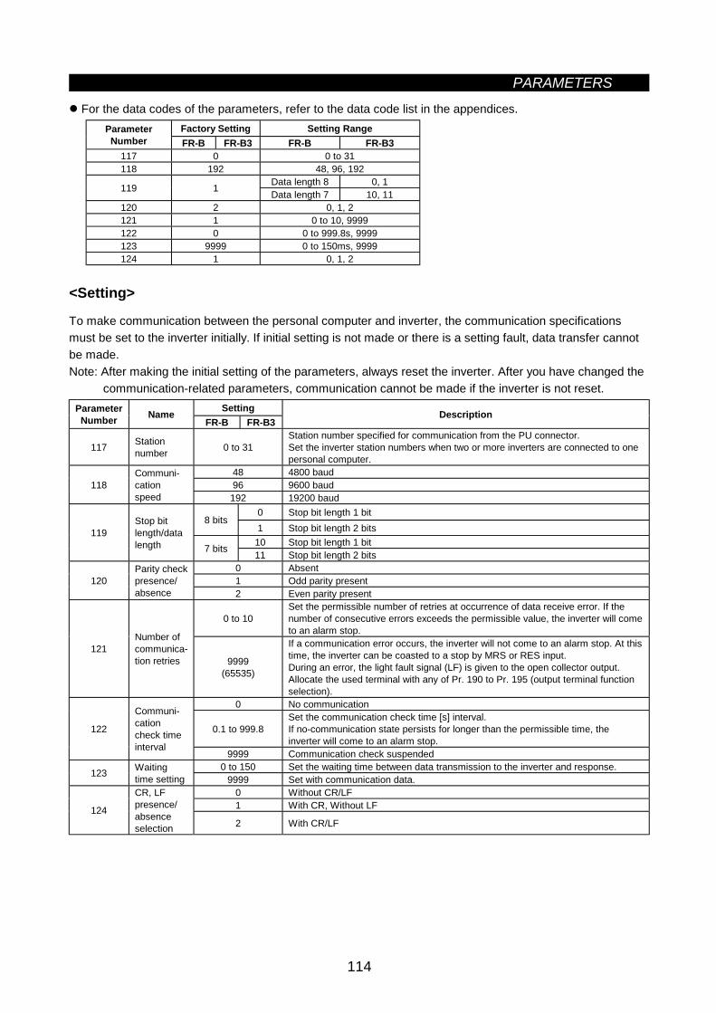
PARAMETERS
114
For the data codes of the parameters, refer to the data code list in the appendices.Factory Setting Setting RangeParameter
Number FR-B FR-B3 FR-B FR-B3117 0 0 to 31118 192 48, 96, 192
Data length 8 0, 1119 1 Data length 7 10, 11120 2 0, 1, 2121 1 0 to 10, 9999122 0 0 to 999.8s, 9999123 9999 0 to 150ms, 9999124 1 0, 1, 2
<Setting>
To make communication between the personal computer and inverter, the communication specificationsmust be set to the inverter initially. If initial setting is not made or there is a setting fault, data transfer cannotbe made.Note: After making the initial setting of the parameters, always reset the inverter. After you have changed the
communication-related parameters, communication cannot be made if the inverter is not reset.SettingParameter
Number NameFR-B FR-B3
Description
117 Stationnumber 0 to 31
Station number specified for communication from the PU connector.Set the inverter station numbers when two or more inverters are connected to onepersonal computer.
48 4800 baud96 9600 baud118
Communi-cationspeed 192 19200 baud
0 Stop bit length 1 bit8 bits
1 Stop bit length 2 bits10 Stop bit length 1 bit
119Stop bitlength/datalength 7 bits 11 Stop bit length 2 bits
0 Absent1 Odd parity present120
Parity checkpresence/absence 2 Even parity present
0 to 10Set the permissible number of retries at occurrence of data receive error. If thenumber of consecutive errors exceeds the permissible value, the inverter will cometo an alarm stop.
121Number ofcommunica-tion retries 9999
(65535)
If a communication error occurs, the inverter will not come to an alarm stop. At thistime, the inverter can be coasted to a stop by MRS or RES input.During an error, the light fault signal (LF) is given to the open collector output.Allocate the used terminal with any of Pr. 190 to Pr. 195 (output terminal functionselection).
0 No communication
0.1 to 999.8Set the communication check time [s] interval.If no-communication state persists for longer than the permissible time, theinverter will come to an alarm stop.
122
Communi-cationcheck timeinterval
9999 Communication check suspended0 to 150 Set the waiting time between data transmission to the inverter and response.123 Waiting
time setting 9999 Set with communication data.0 Without CR/LF1 With CR, Without LF124
CR, LFpresence/absenceselection 2 With CR/LF
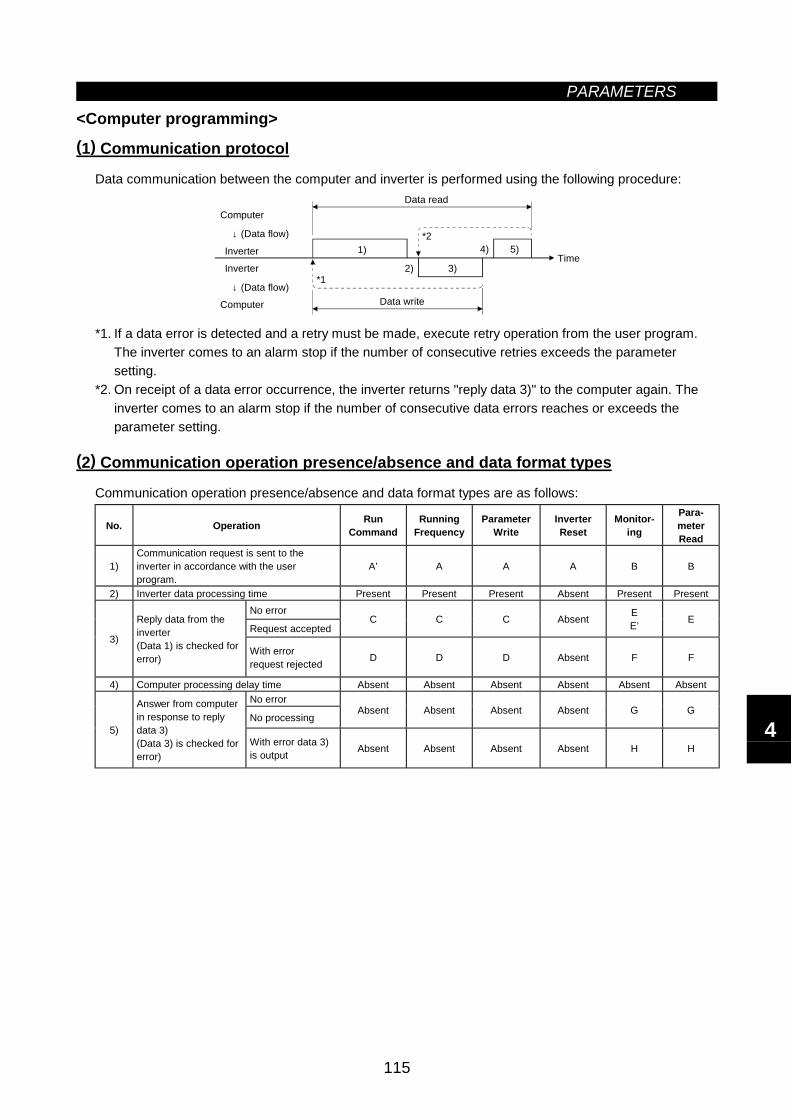
PARAMETERS
115
<Computer programming>(1) Communication protocol
Data communication between the computer and inverter is performed using the following procedure:
*1
*2
Computer
Inverter
↓ (Data flow)
Computer
↓ (Data flow)
Inverter
Data read
Data write
Time1)
2) 3)
4) 5)
*1. If a data error is detected and a retry must be made, execute retry operation from the user program.The inverter comes to an alarm stop if the number of consecutive retries exceeds the parametersetting.
*2. On receipt of a data error occurrence, the inverter returns "reply data 3)" to the computer again. Theinverter comes to an alarm stop if the number of consecutive data errors reaches or exceeds theparameter setting.
(2) Communication operation presence/absence and data format types
Communication operation presence/absence and data format types are as follows:
No. Operation RunCommand
RunningFrequency
ParameterWrite
InverterReset
Monitor-ing
Para-meterRead
1)Communication request is sent to theinverter in accordance with the userprogram.
A’ A A A B B
2) Inverter data processing time Present Present Present Absent Present PresentNo error
Request acceptedC C C Absent E
E’ E
3)
Reply data from theinverter(Data 1) is checked forerror)
With errorrequest rejected D D D Absent F F
4) Computer processing delay time Absent Absent Absent Absent Absent AbsentNo error
No processingAbsent Absent Absent Absent G G
5)
Answer from computerin response to replydata 3)(Data 3) is checked forerror)
With error data 3)is output Absent Absent Absent Absent H H
4
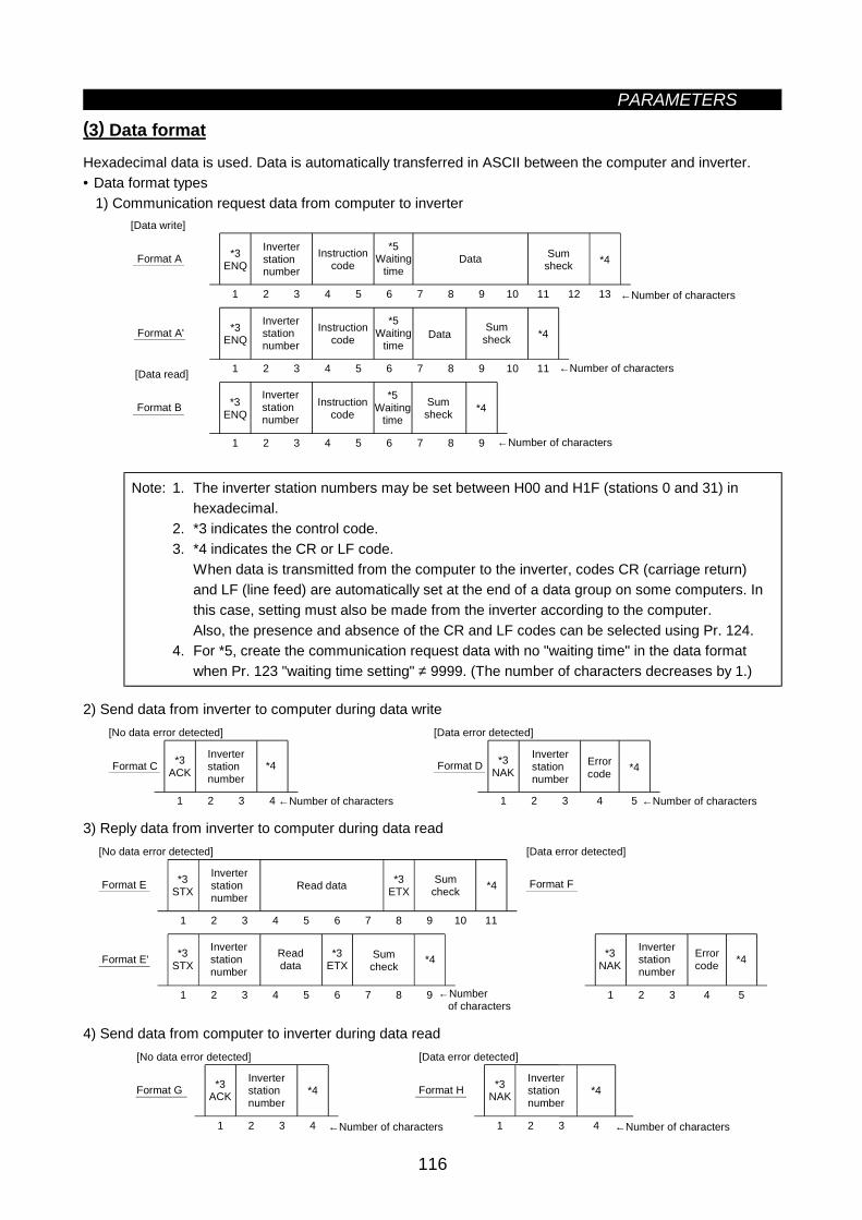
PARAMETERS
116
(3) Data format
Hexadecimal data is used. Data is automatically transferred in ASCII between the computer and inverter.• Data format types
1) Communication request data from computer to inverter
*3ENQ *4
1 2 3 4 5 6 7 8 9 10 11 12 13
*3ENQ *4
1 2 3 4 5 6 7 8 9 10 11
*3ENQ *4
1 2 3 4 5 6 7 8 9
[Data write]
Format A
[Data read]
Format A'
Format B
Inverterstationnumber
Instructioncode
*5Waiting
time
Data
Sumsheck
Inverterstationnumber
Inverterstationnumber
Instructioncode
Instructioncode
*5Waiting
time
*5Waiting
time
Data
Sumsheck
Sumsheck
←Number of characters
←Number of characters
←Number of characters
Note: 1. The inverter station numbers may be set between H00 and H1F (stations 0 and 31) inhexadecimal.
2. *3 indicates the control code.3. *4 indicates the CR or LF code.
When data is transmitted from the computer to the inverter, codes CR (carriage return)and LF (line feed) are automatically set at the end of a data group on some computers. Inthis case, setting must also be made from the inverter according to the computer.Also, the presence and absence of the CR and LF codes can be selected using Pr. 124.
4. For *5, create the communication request data with no "waiting time" in the data formatwhen Pr. 123 "waiting time setting" ≠ 9999. (The number of characters decreases by 1.)
2) Send data from inverter to computer during data write
*3ACK *4
1 2 3 4
*3NAK
1 2 3 4
*4
5
[No data error detected] [Data error detected]
Format C Format DInverterstationnumber
Inverterstationnumber
Errorcode
←Number of characters ←Number of characters
3) Reply data from inverter to computer during data read
1 2 3 4 5
1 2 3 4 5 6 7 8 9 10 11
[No data error detected]
1 2 3 4 5 6 7 8 9
*3STXFormat E
Inverterstationnumber
Readdata
Sumcheck
←Number of characters
Format E'
*3ETX *4Read data
Inverterstationnumber
Sumcheck *4*3
ETX*3
STX
[Data error detected]
Format F
*3NAK
Errorcode *4
Inverterstationnumber
4) Send data from computer to inverter during data read
1 2 3 4 1 2 3 4
[No data error detected]
*3ACKFormat G
Inverterstationnumber
←Number of characters
Format H*4 *3NAK
[Data error detected]
*4Inverterstationnumber
←Number of characters
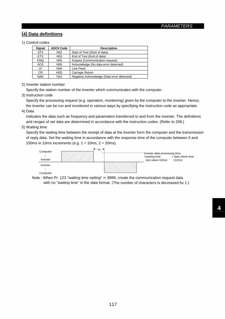
PARAMETERS
117
(4) Data definitions
1) Control codesSignal ASCII Code DescriptionSTX H02 Start of Text (Start of data)ETX H03 End of Text (End of data)ENQ H05 Enquiry (Communication request)ACK H06 Acknowledge (No data error detected)LF H0A Line FeedCR H0D Carriage Return
NAK H15 Negative Acknowledge (Data error detected)
2) Inverter station numberSpecify the station number of the inverter which communicates with the computer.
3) Instruction codeSpecify the processing request (e.g. operation, monitoring) given by the computer to the inverter. Hence,the inverter can be run and monitored in various ways by specifying the instruction code as appropriate.
4) DataIndicates the data such as frequency and parameters transferred to and from the inverter. The definitionsand ranges of set data are determined in accordance with the instruction codes. (Refer to 208.)
5) Waiting timeSpecify the waiting time between the receipt of data at the inverter form the computer and the transmissionof reply data. Set the waiting time in accordance with the response time of the computer between 0 and150ms in 10ms increments (e.g. 1 = 10ms, 2 = 20ms).
Computer↓
Inverter
Inverter↓
Computer
Inverter data processing time=waiting time + data check time (set value×10ms) (12ms)
(The number of characters is decreased by 1.)Note : When Pr. 123 "waiting time setting" , 9999, create the communication request data with no "waiting time" in the data format.
4
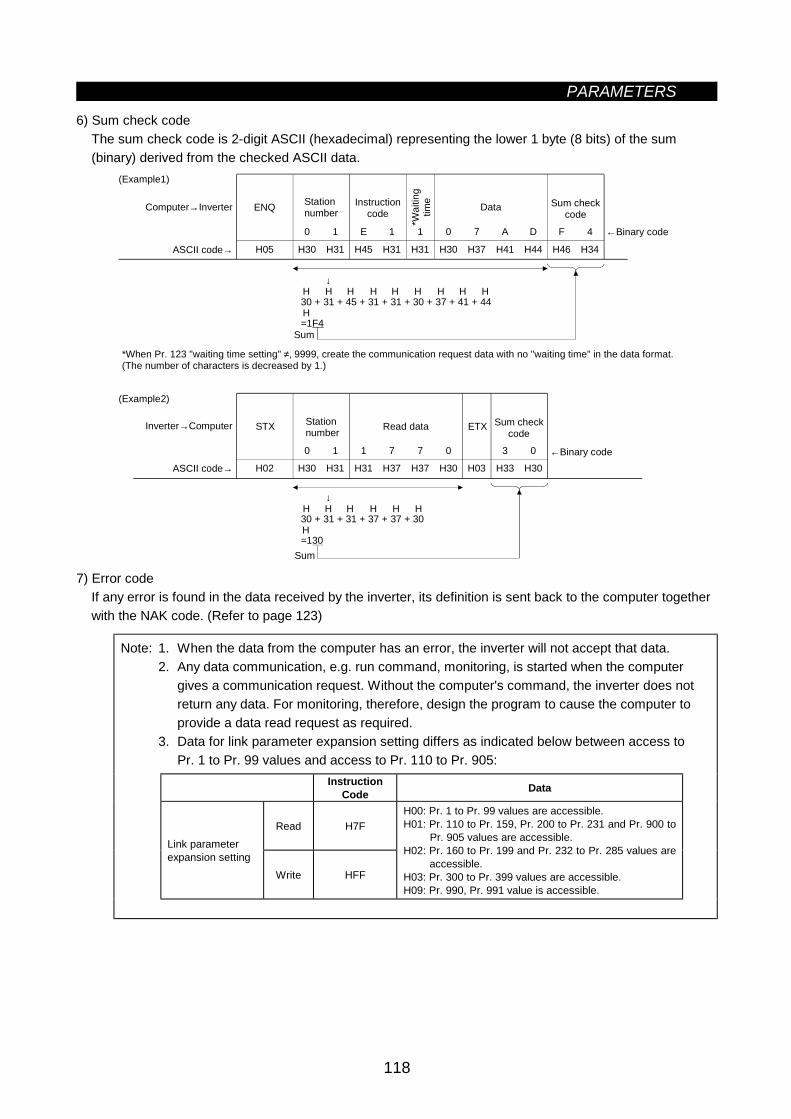
PARAMETERS
118
6) Sum check codeThe sum check code is 2-digit ASCII (hexadecimal) representing the lower 1 byte (8 bits) of the sum(binary) derived from the checked ASCII data.
↓
30 + 31 + 31 + 37 + 37 + 30
=130
10 1 E 1 0 7 A D F 4
H05 H30 H31 H31H45 H31 H30 H37 H41 H44 H46 H34
(Example1)
Computer→Inverter
ASCII code→
Stationnumber
Instructioncode
*Wai
ting
time
Data Sum checkcode
←Binary code
Sum
↓
30 + 31 + 45 + 31 + 31 + 30 + 37 + 41 + 44
=1F4
HH H H H H H H H
H
0 1 1 7 0 3 0
H02 H30 H31 H37H31 H37 H30 H03 H33 H30
7
(Example2)
Inverter→Computer
ASCII code→
←Binary code
Sum checkcode
STX Stationnumber Read data ETX
Sum
HH H H H H
H
ENQ
*When Pr. 123 "waiting time setting" ≠‚ 9999, create the communication request data with no "waiting time" in the data format. (The number of characters is decreased by 1.)
7) Error codeIf any error is found in the data received by the inverter, its definition is sent back to the computer togetherwith the NAK code. (Refer to page 123)
Note: 1. When the data from the computer has an error, the inverter will not accept that data.2. Any data communication, e.g. run command, monitoring, is started when the computer
gives a communication request. Without the computer's command, the inverter does notreturn any data. For monitoring, therefore, design the program to cause the computer toprovide a data read request as required.
3. Data for link parameter expansion setting differs as indicated below between access toPr. 1 to Pr. 99 values and access to Pr. 110 to Pr. 905:
InstructionCode Data
Read H7FLink parameterexpansion setting
Write HFF
H00: Pr. 1 to Pr. 99 values are accessible.H01: Pr. 110 to Pr. 159, Pr. 200 to Pr. 231 and Pr. 900 to
Pr. 905 values are accessible.H02: Pr. 160 to Pr. 199 and Pr. 232 to Pr. 285 values are
accessible.H03: Pr. 300 to Pr. 399 values are accessible.H09: Pr. 990, Pr. 991 value is accessible.
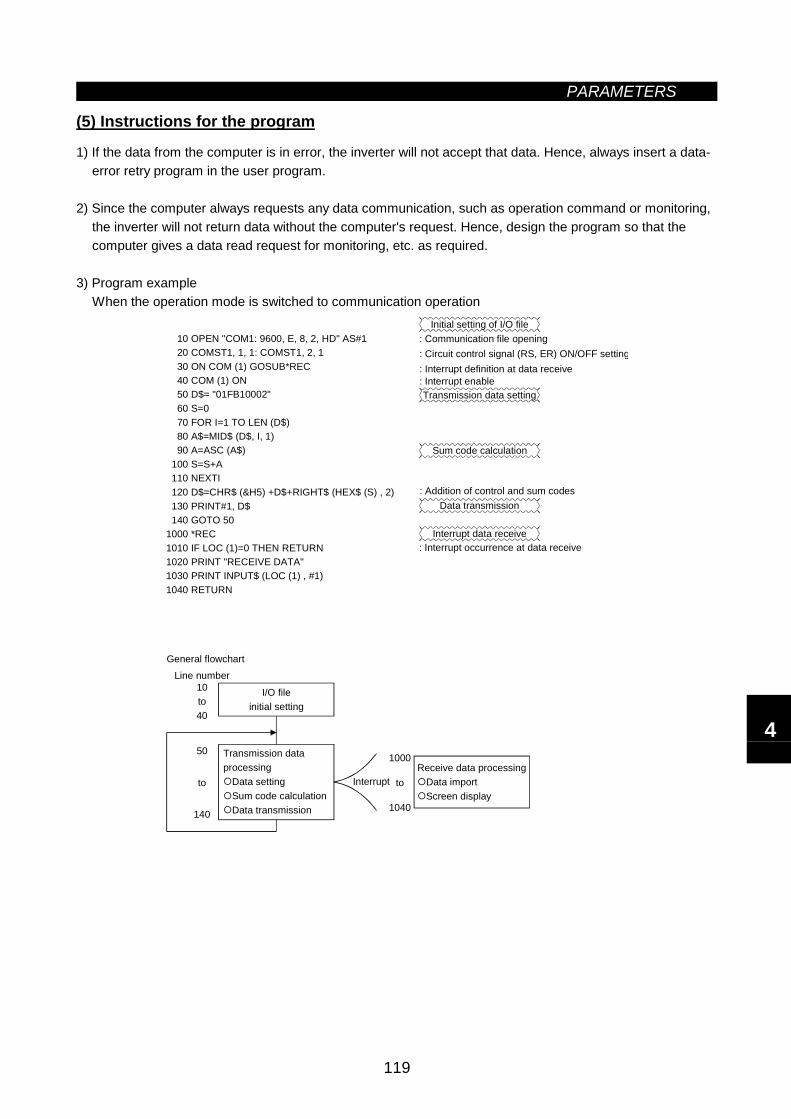
PARAMETERS
119
(5) Instructions for the program
1) If the data from the computer is in error, the inverter will not accept that data. Hence, always insert a data-error retry program in the user program.
2) Since the computer always requests any data communication, such as operation command or monitoring,the inverter will not return data without the computer's request. Hence, design the program so that thecomputer gives a data read request for monitoring, etc. as required.
3) Program exampleWhen the operation mode is switched to communication operation
I/O file initial setting
10 OPEN "COM1: 9600, E, 8, 2, HD" AS#1 20 COMST1, 1, 1: COMST1, 2, 1 30 ON COM (1) GOSUB*REC 40 COM (1) ON 50 D$= "01FB10002" 60 S=0 70 FOR I=1 TO LEN (D$) 80 A$=MID$ (D$, I, 1) 90 A=ASC (A$) 100 S=S+A 110 NEXTI 120 D$=CHR$ (&H5) +D$+RIGHT$ (HEX$ (S) , 2) 130 PRINT#1, D$ 140 GOTO 501000 *REC1010 IF LOC (1)=0 THEN RETURN1020 PRINT "RECEIVE DATA"1030 PRINT INPUT$ (LOC (1) , #1)1040 RETURN
Initial setting of I/O file: Communication file opening: Circuit control signal (RS, ER) ON/OFF setting: Interrupt definition at data receive: Interrupt enableTransmission data setting
Sum code calculation
: Addition of control and sum codesData transmission
Interrupt data receive: Interrupt occurrence at data receive
Receive data processingData importScreen display
General flowchartLine number
10
40
50
140
Transmission data processing
Data settingSum code calculationData transmission
Interrupt
1000
1040
to
to to
4
PARAMETERS
120
CAUTION When the inverter's communication check time interval is not set, interlocks areprovided to disable operation to prevent hazard. Always set the communication checktime interval before starting operation.
Data communication is not started automatically but is made only when the computerprovides a communication request. If communication is disabled during operation dueto signal cable breakage etc, the inverter cannot be stopped. When thecommunication check time interval has elapsed, the inverter will come to an alarmstop (E.PUE).The inverter can be coasted to a stop by switching on its RES signal or by switchingpower off.
If communication is halted due to signal cable breakage, computer fault etc., theinverter does not detect such a fault. This should be fully noted.

PARAMETERS
121
<Setting items and set data>
After completion of parameter setting, set the instruction codes and data and start communication from thecomputer to allow various types of operation control and monitoring.
No. Item InstructionCode Description Number of
Data Digits
Read H7BH0000: Communication option operationH0001: External operationH0002: Communication operation (PU connector)1 Operation
modeWrite HFB
H0000: Communication option operationH0001: External operationH0002: Communication operation (PU connector)
4 digits
Output frequency[speed] H6F
H0000 to HFFFF: Output frequency (hexadecimal) in 0.01Hzincrements[Speed (hexadecimal) in 1r/min increments if Pr. 37 = 1 to 9998or Pr. 144 = 2 to 10, 102 to 110.]
4 digits
Output current H70 H0000 to HFFFF: Output current (hexadecimal) in 0.01Aincrements 4 digits
Output voltage H71 H0000 to HFFFF: Output voltage (hexadecimal) in 0.1Vincrements 4 digits
Special monitor H72 H0000 to HFFFF: Monitored data selected by instruction codeHF3 4 digits
H01 to H0E Monitor selection data
Data Description Incre-ments Data Description Incre-
ments
H01Outputfrequency
0.01Hz H09Regenerativebrake
0.1%Read H73
H02 Output current 0.01A H0A
Electronicovercurrentprotection loadfactor
0.1%
H03 Output voltage 0.1V H0BOutput currentpeak value
0.01A
H05Frequencysetting
0.01Hz H0CConverter outputvoltage peakvalue
0.1V
H06Runningspeed
r/min H0D Input power 0.01kW
H07 Motor torque 0.1% H0E Output power 0.01kW
Special monitorselection No.
Write HF3
2 digits
H0000 to HFFFF: Two most recent alarm definitions
Read data: [Example] H30A0
Most recent alarm(HA0)
b15 b8b7 b0
0 0 1 1 0 0 0 0 0 0 0 0 00 1 1
(Previous alarm ........ THT)(Most recent alarm ..... OPT)
Previous alarm(H30)
Alarm definition display example (for instruction code H74)
Alarm dataData Description Data Description Data DescriptionH00 No alarm H51 UVT HB1 PUEH10 0C1 H60 OLT HB2 RETH11 0C2 H70 BE HC1 CTEH12 0C3 H80 GF HC2 P24H20 0V1 H81 LF HD5 MB1H21 0V2 H90 OHT HD6 MB2H22 0V3 HA0 OPT HD7 MB3H30 THT HA1 OP1 HD8 MB4H31 THM HA2 OP2 HD9 MB5H40 FIN HA3 OP3 HDA MB6H50 IPF HB0 PE HDB MB7
2
Mon
itorin
g
Alarm definition H74 to H77 4 digits
4
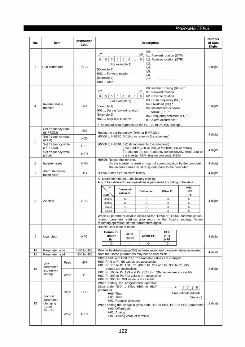
PARAMETERS
122
No. Item InstructionCode Description
Numberof DataDigits
3 Run command HFA
b0: b1: Forward rotation (STF)b2: Reverse rotation (STR)b3: b4: b5: b6: b7:
0 0 0 0 0 0 01b7 b0
[Example 1] H02 ... Forward rotation[Example 2] H00 ... Stop
(For example 1)2 digits
4 Inverter statusmonitor H7A
b0: Inverter running (RUN) *b1: Forward rotationb2: Reverse rotationb3: Up to frequency (SU) *b4: Overload (OL) *b5: Instantaneous power failure (IPF) *b6: Frequency detection (FU) *b7: Alarm occurrence *
0 0 0 0 0 0 01b7 b0
[Example 1] H02 ... During forward rotation[Example 2] H80 ... Stop due to alarm
(For example 1)
*The output data depends on the Pr. 190 to Pr. 195 settings.
2 digits
Set frequency read(E2PROM) H6E
Set frequency read(RAM) H6D
Reads the set frequency (RAM or E2PROM).H0000 to H2EE0: 0.01Hz increments (hexadecimal) 4 digits
Set frequency write(E2PROM) HEE
5
Set frequency write(RAM) HED
H0000 to H9C40: 0.01Hz increments (hexadecimal)[0 to 120Hz (22K or less)/0 to 60Hz(30K or more)]To change the set frequency consecutively, write data tothe inverter RAM. (Instruction code: HED)
4 digits
6 Inverter reset HFDH9696: Resets the inverter.
As the inverter is reset on start of communication by the computer,the inverter cannot send reply data back to the computer.
4 digits
7 Alarm definitionbatch clear HF4 H9696: Batch clear of alarm history 4 digits
All parameters return to the factory settings.Any of four different clear operations is performed according to the data.
Pr.
Data
Communi-cation Pr. Calibration Other Pr.
HECHF3HFF
H9696 ×H9966H5A5A × ×H55AA ×
8 All clear HFC
When all parameter clear is executed for H9696 or H9966, communication-related parameter settings also return to the factory settings. Whenresuming operation, set the parameters again.
4 digits
H9669: User clear is made.Communi
-cationPr.
Calib-ration Other Pr.
HECHF3HFF
×
9 User clear HFC 4 digits
10 Parameter write H80 to HE311 Parameter read H00 to H63
Refer to the data list (page 208) and write and/or read parameter values as required.Note that some parameters may not be accessible. 4 digits
Read H7F
12Linkparameterexpansionsetting Write HFF
H00 to H6C and H80 to HEC parameter values are changed.H00: Pr. 0 to Pr. 96 values are accessible.H01: Pr. 110 to Pr. 158 , Pr. 200 to Pr. 231 and Pr. 900 to Pr. 905 values are accessible.H02: Pr. 160 to Pr. 199 and Pr. 232 to Pr. 287 values are accessible.H03: Pr. 300 to Pr. 342 values are accessible.H09: Pr. 990, Pr. 991 value is accessible.
2 digits
Read H6C
When setting the programmed operation(data code H3D to H5A, HBD to HDA)parameter
H00: TimeH01: TimeH02: Rotation direction
6 3 3 B
Time (Minute) Minute(Second)
13
Secondparameterchanging(CodeFF = 1)
Write HEC
When setting the bias/gain (data code H5E to HBA, HDE to HED) parameterH00: Offset/gainH01: AnalogH02: Analog value of terminal
2 digits
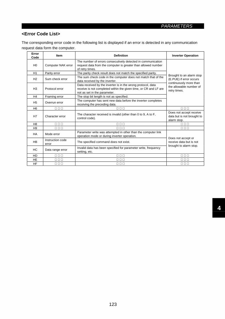
PARAMETERS
123
<Error Code List>
The corresponding error code in the following list is displayed if an error is detected in any communicationrequest data form the computer.
ErrorCode Item Definition Inverter Operation
H0 Computer NAK errorThe number of errors consecutively detected in communicationrequest data from the computer is greater than allowed numberof retry times.
H1 Parity error The parity check result does not match the specified parity.
H2 Sum check error The sum check code in the computer does not match that of thedata received by the inverter.
H3 Protocol errorData received by the inverter is in the wrong protocol, datareceive is not completed within the given time, or CR and LF arenot as set in the parameter.
H4 Framing error The stop bit length is not as specified.
H5 Overrun error The computer has sent new data before the inverter completesreceiving the preceding data.
Brought to an alarm stop(E.PUE) if error occurscontinuously more thanthe allowable number ofretry times.
H6
H7 Character error The character received is invalid (other than 0 to 9, A to F,control code).
Does not accept receivedata but is not brought toalarm stop.
H8 H9
HA Mode error Parameter write was attempted in other than the computer linkoperation mode or during inverter operation.
HB Instruction codeerror The specified command does not exist.
HC Data range error Invalid data has been specified for parameter write, frequencysetting, etc.
Does not accept orreceive data but is notbrought to alarm stop.
HD HE HF
4
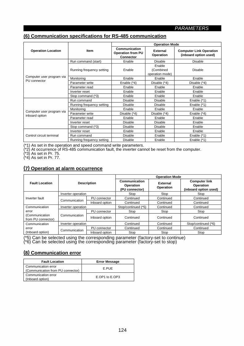
PARAMETERS
124
(6) Communication specifications for RS-485 communicationOperation Mode
Operation Location Item CommunicationOperation from PU
Connector
ExternalOperation
Computer Link Operation(inboard option used)
Run command (start) Enable Disable Disable
Running frequency setting EnableEnable
(Combinedoperation mode)
Disable
Monitoring Enable Enable EnableParameter write Enable (*4) Disable (*4) Disable (*4)Parameter read Enable Enable EnableInverter reset Enable Enable Enable
Computer user program viaPU connector
Stop command (*3) Enable Enable EnableRun command Disable Disable Enable (*1)Running frequency setting Disable Disable Enable (*1)Monitoring Enable Enable EnableParameter write Disable (*4) Disable (*4) Enable (*4)Parameter read Enable Enable EnableInverter reset Disable Disable Enable
Computer user program viainboard option
Stop command (*3) Disable Disable EnableInverter reset Enable Enable EnableRun command Disable Enable Enable (*1)Control circuit terminalRunning frequency setting Disable Enable Enable (*1)
(*1) As set in the operation and speed command write parameters.(*2) At occurrence of RS-485 communication fault, the inverter cannot be reset from the computer.(*3) As set in Pr. 75.(*4) As set in Pr. 77.
(7) Operation at alarm occurrenceOperation Mode
Fault Location Description CommunicationOperation
(PU connector)
ExternalOperation
Computer linkOperation
(inboard option used)Inverter operation Stop Stop Stop
PU connector Continued Continued ContinuedInverter fault Communication Inboard option Continued Continued ContinuedInverter operation Stop/continued (*5) Continued Continued
PU connector Stop Stop StopCommunicationerror(Communicationfrom PU connector)
Communication Inboard option Continued Continued Continued
Inverter operation Continued Continued Stop/continued (*6)PU connector Continued Continued Continued
Communicationerror(Inboard option) Communication Inboard option Stop Stop Stop
(*5) Can be selected using the corresponding parameter (factory-set to continue)(*6) Can be selected using the corresponding parameter (factory-set to stop)
(8) Communication errorFault Location Error Message
Communication error(Communication from PU connector) E.PUE
Communication error(Inboard option) E.OP1 to E.OP3
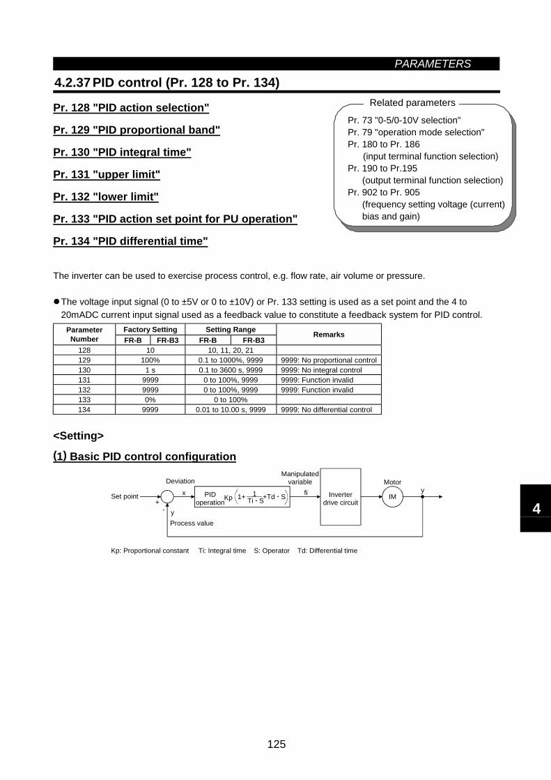
PARAMETERS
125
Pr. 73 "0-5/0-10V selection"Pr. 79 "operation mode selection"Pr. 180 to Pr. 186
(input terminal function selection)Pr. 190 to Pr.195
(output terminal function selection)Pr. 902 to Pr. 905
(frequency setting voltage (current)bias and gain)
Related parameters
4.2.37 PID control (Pr. 128 to Pr. 134)
Pr. 128 "PID action selection"
Pr. 129 "PID proportional band"
Pr. 130 "PID integral time"
Pr. 131 "upper limit"
Pr. 132 "lower limit"
Pr. 133 "PID action set point for PU operation"
Pr. 134 "PID differential time"
The inverter can be used to exercise process control, e.g. flow rate, air volume or pressure.
The voltage input signal (0 to ±5V or 0 to ±10V) or Pr. 133 setting is used as a set point and the 4 to20mADC current input signal used as a feedback value to constitute a feedback system for PID control.
Factory Setting Setting RangeParameterNumber FR-B FR-B3 FR-B FR-B3
Remarks
128 10 10, 11, 20, 21129 100% 0.1 to 1000%, 9999 9999: No proportional control130 1 s 0.1 to 3600 s, 9999 9999: No integral control131 9999 0 to 100%, 9999 9999: Function invalid132 9999 0 to 100%, 9999 9999: Function invalid133 0% 0 to 100%134 9999 0.01 to 10.00 s, 9999 9999: No differential control
<Setting>(1) Basic PID control configuration
+-
x
y
fi IMy
Ti S11+ +Td S
Kp: Proportional constant Ti: Integral time S: Operator Td: Differential time
Set point
Deviation
KpPIDoperation
Manipulatedvariable
Inverterdrive circuit
Motor
Process value
4
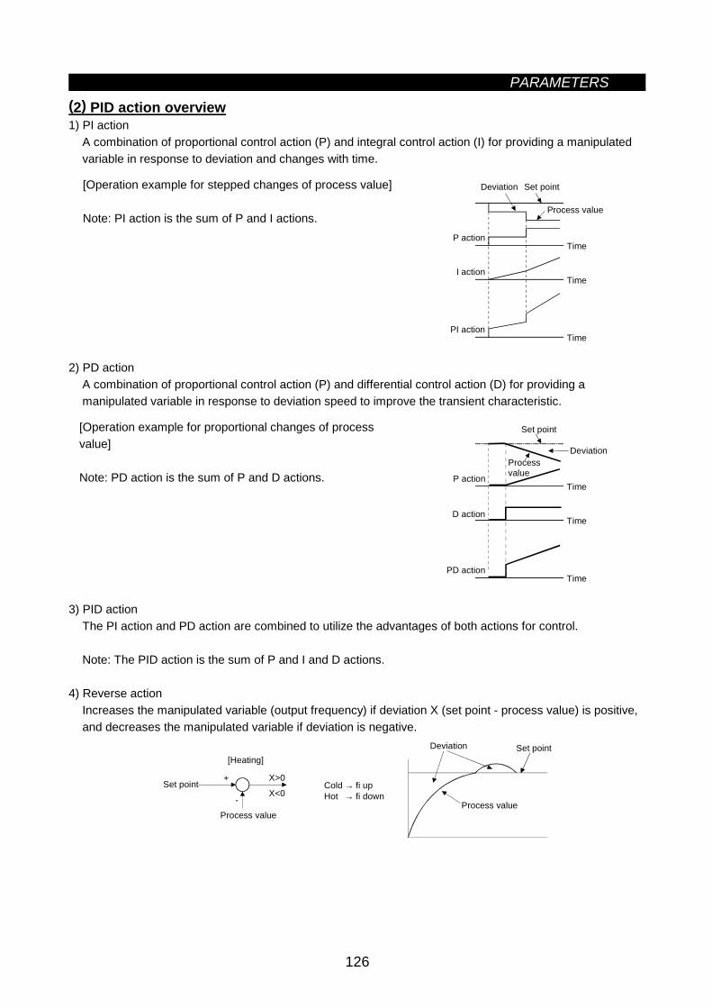
PARAMETERS
126
(2) PID action overview1) PI action
A combination of proportional control action (P) and integral control action (I) for providing a manipulatedvariable in response to deviation and changes with time.
[Operation example for stepped changes of process value]
Note: PI action is the sum of P and I actions.
Time
Time
Time
Process value
P action
I action
PI action
Deviation Set point
2) PD actionA combination of proportional control action (P) and differential control action (D) for providing amanipulated variable in response to deviation speed to improve the transient characteristic.
[Operation example for proportional changes of processvalue]
Note: PD action is the sum of P and D actions.Time
Time
Time
Deviation
P action
D action
PD action
Set point
Processvalue
3) PID actionThe PI action and PD action are combined to utilize the advantages of both actions for control.
Note: The PID action is the sum of P and I and D actions.
4) Reverse actionIncreases the manipulated variable (output frequency) if deviation X (set point - process value) is positive,and decreases the manipulated variable if deviation is negative.
X>0
X<0+
- Process value
Set point
[Heating]
Process value
Cold → fi upHot → fi down
Deviation Set point
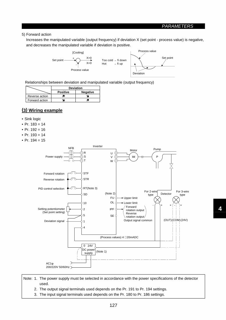
PARAMETERS
127
5) Forward actionIncreases the manipulated variable (output frequency) if deviation X (set point - process value) is negative,and decreases the manipulated variable if deviation is positive.
X>0
X<0+
-
Set pointToo cold → fi downHot → fi up
Set point
[Cooling]
Process value
Process value
Deviation
Relationships between deviation and manipulated variable (output frequency)Deviation
Positive NegativeReverse actionForward action
(3) Wiring example
• Sink logic• Pr. 183 = 14• Pr. 192 = 16• Pr. 193 = 14• Pr. 194 = 15
NFB
0 24V
AC1φ200/220V 50/60Hz
RST
STF
STR
RT(Note 3)
SD
10
2
5
1
4
UVW
(Note 2)FUOL
SE
(Process values) 4 ∼ 20mADC
IM P
-+ + +-
(OUT) (24V)
IPF
(Note 1)
Power supply
Forward rotation
Reverse rotation
PID control selection
Setting potentiometer(Set point setting)
Deviation signal
InverterMotor Pump
Upper limit
Lower limitForwardrotation outputReverserotation output
Output signal common
For 2-wiretype Detector
For 3-wiretype
DC powersupply
(COM)
Note: 1. The power supply must be selected in accordance with the power specifications of the detectorused.
2. The output signal terminals used depends on the Pr. 191 to Pr. 194 settings.3. The input signal terminals used depends on the Pr. 180 to Pr. 186 settings.
4
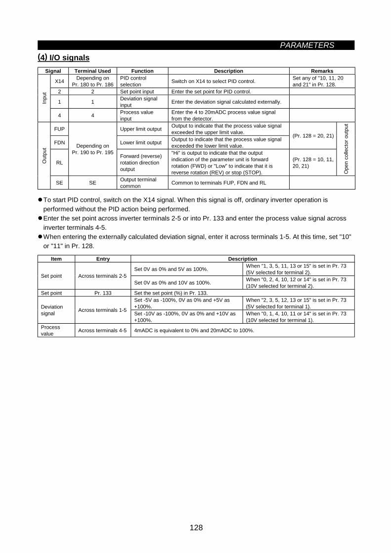
PARAMETERS
128
(4) I/O signalsSignal Terminal Used Function Description Remarks
X14 Depending onPr. 180 to Pr. 186
PID controlselection Switch on X14 to select PID control. Set any of "10, 11, 20
and 21" in Pr. 128.2 2 Set point input Enter the set point for PID control.
1 1 Deviation signalinput Enter the deviation signal calculated externally.In
put
4 4 Process valueinput
Enter the 4 to 20mADC process value signalfrom the detector.
FUP Upper limit output Output to indicate that the process value signalexceeded the upper limit value.
FDN Lower limit output Output to indicate that the process value signalexceeded the lower limit value.
(Pr. 128 = 20, 21)
RL
Depending onPr. 190 to Pr. 195
Forward (reverse)rotation directionoutput
"Hi" is output to indicate that the outputindication of the parameter unit is forwardrotation (FWD) or "Low" to indicate that it isreverse rotation (REV) or stop (STOP).
(Pr. 128 = 10, 11,20, 21)
Ope
n co
llect
or o
utpu
t
Out
put
SE SE Output terminalcommon Common to terminals FUP, FDN and RL
To start PID control, switch on the X14 signal. When this signal is off, ordinary inverter operation isperformed without the PID action being performed.Enter the set point across inverter terminals 2-5 or into Pr. 133 and enter the process value signal acrossinverter terminals 4-5.When entering the externally calculated deviation signal, enter it across terminals 1-5. At this time, set "10"or "11" in Pr. 128.
Item Entry Description
Set 0V as 0% and 5V as 100%. When "1, 3, 5, 11, 13 or 15" is set in Pr. 73(5V selected for terminal 2).Set point Across terminals 2-5
Set 0V as 0% and 10V as 100%. When "0, 2, 4, 10, 12 or 14" is set in Pr. 73(10V selected for terminal 2).
Set point Pr. 133 Set the set point (%) in Pr. 133.Set -5V as -100%, 0V as 0% and +5V as+100%.
When "2, 3, 5, 12, 13 or 15" is set in Pr. 73(5V selected for terminal 1).Deviation
signal Across terminals 1-5 Set -10V as -100%, 0V as 0% and +10V as+100%.
When "0, 1, 4, 10, 11 or 14" is set in Pr. 73(10V selected for terminal 1).
Processvalue Across terminals 4-5 4mADC is equivalent to 0% and 20mADC to 100%.
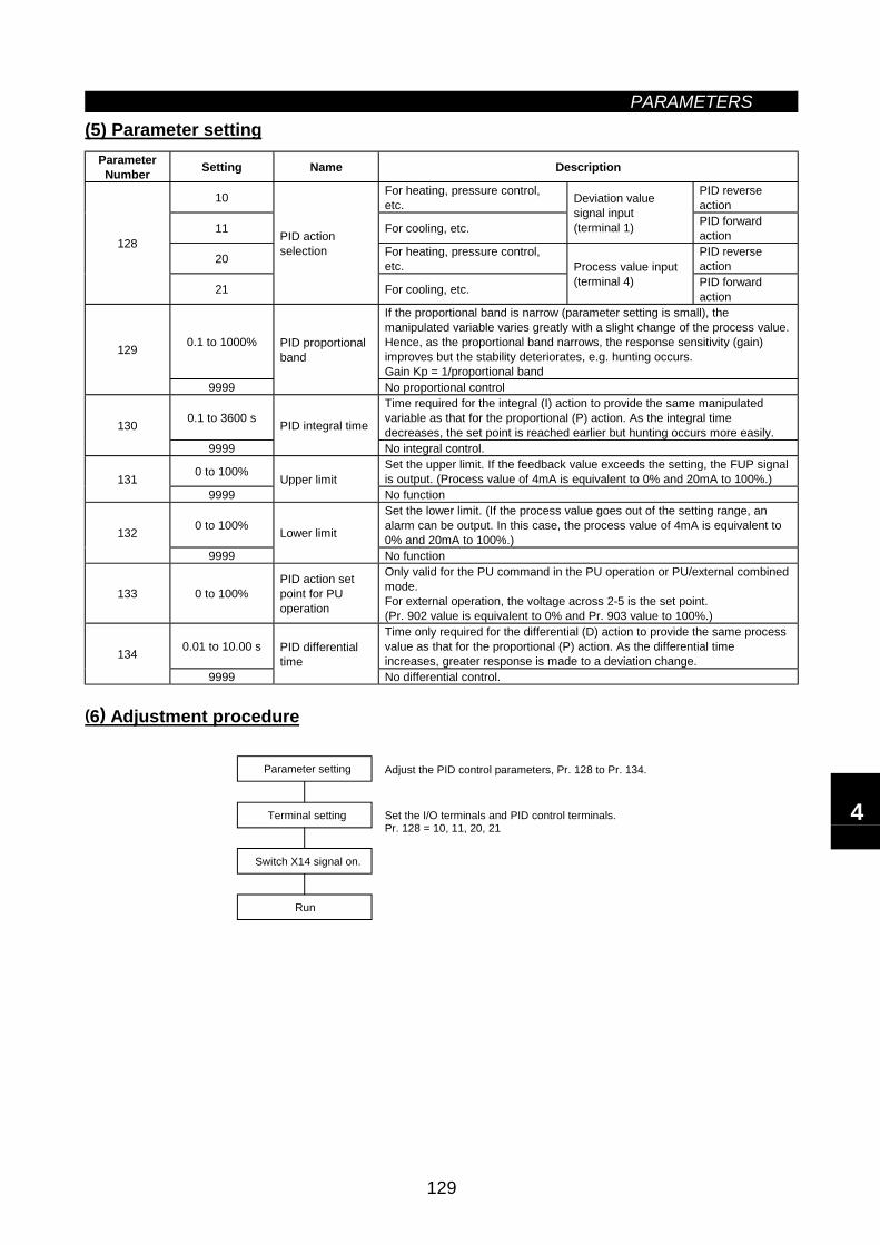
PARAMETERS
129
(5) Parameter settingParameterNumber Setting Name Description
10 For heating, pressure control,etc.
PID reverseaction
11 For cooling, etc.
Deviation valuesignal input(terminal 1) PID forward
action
20 For heating, pressure control,etc.
PID reverseaction
128
21
PID actionselection
For cooling, etc.
Process value input(terminal 4) PID forward
action
0.1 to 1000%
If the proportional band is narrow (parameter setting is small), themanipulated variable varies greatly with a slight change of the process value.Hence, as the proportional band narrows, the response sensitivity (gain)improves but the stability deteriorates, e.g. hunting occurs.Gain Kp = 1/proportional band
129
9999
PID proportionalband
No proportional control
0.1 to 3600 sTime required for the integral (I) action to provide the same manipulatedvariable as that for the proportional (P) action. As the integral timedecreases, the set point is reached earlier but hunting occurs more easily.130
9999
PID integral time
No integral control.
0 to 100% Set the upper limit. If the feedback value exceeds the setting, the FUP signalis output. (Process value of 4mA is equivalent to 0% and 20mA to 100%.)131
9999Upper limit
No function
0 to 100%Set the lower limit. (If the process value goes out of the setting range, analarm can be output. In this case, the process value of 4mA is equivalent to0% and 20mA to 100%.)132
9999
Lower limit
No function
133 0 to 100%PID action setpoint for PUoperation
Only valid for the PU command in the PU operation or PU/external combinedmode.For external operation, the voltage across 2-5 is the set point.(Pr. 902 value is equivalent to 0% and Pr. 903 value to 100%.)
0.01 to 10.00 sTime only required for the differential (D) action to provide the same processvalue as that for the proportional (P) action. As the differential timeincreases, greater response is made to a deviation change.134
9999
PID differentialtime
No differential control.
(6) Adjustment procedure
Set the I/O terminals and PID control terminals.Pr. 128 = 10, 11, 20, 21
Parameter setting
Terminal setting
Switch X14 signal on.
Run
Adjust the PID control parameters, Pr. 128 to Pr. 134.
4
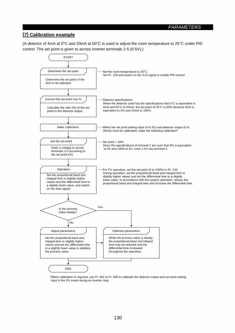
PARAMETERS
130
(7) Calibration example
(A detector of 4mA at 0°C and 20mA at 50°C is used to adjust the room temperature to 25°C under PIDcontrol. The set point is given to across inverter terminals 2-5 (0-5V).)
*When calibration is required, use Pr. 902 to Pr. 905 to calibrate the detector output and set point setting input in the PU mode during an inverter stop.
Yes
No
START
Determine the set point.
Determine the set point of theitem to be adjusted.
Convert the set point into %.
Calculate the ratio (%) of the setpoint to the detector output.
Make calibration.
Set the set point.
Enter a voltage to acrossterminals 2-5 according tothe set point (%).
Operation
Set the proportional band andintegral time to slightly higher values and the differential time toa slightly lower value, and switchon the start signal.
Is the process value steady?
Adjust parameters.
Set the proportional band andintegral time to slightly higher values and set the differential timeto a slightly lower value to stabilize the process value.
END
Optimize parameters.
While the process value is steady,the proportional band and integral time may be reduced and thedifferential time increasedthroughout the operation.
Set the room temperature to 25°C. Set Pr. 128 and switch on the X14 signal to enable PID control.
Detector specifications When the detector used has the specifications that 0°C is equivalent to 4mA and 50°C to 50mA, the set point of 25°C is 50% because 4mA is equivalent to 0% and 20mA to 100%.
When the set point setting input (0 to 5V) and detector output (0 to 20mA) must be calibrated, make the following calibration*.
Set point = 50% Since the specifications of terminal 2 are such that 0% is equivalent to 0V and 100% to 5V, enter 2.5V into terminal 2.
For PU operation, set the set point (0 to 100%) in Pr. 133. During operation, set the proportional band and integral time to slightly higher values and set the differential time to a slightly lower value. In accordance with the system operation, reduce the proportional band and integral time and increase the differential time.
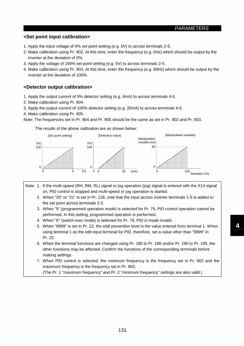
PARAMETERS
131
<Set point input calibration>
1. Apply the input voltage of 0% set point setting (e.g. 0V) to across terminals 2-5.2. Make calibration using Pr. 902. At this time, enter the frequency (e.g. 0Hz) which should be output by the
inverter at the deviation of 0%.3. Apply the voltage of 100% set point setting (e.g. 5V) to across terminals 2-5.4. Make calibration using Pr. 903. At this time, enter the frequency (e.g. 60Hz) which should be output by the
inverter at the deviation of 100%.
<Detector output calibration>
1. Apply the output current of 0% detector setting (e.g. 4mA) to across terminals 4-5.2. Make calibration using Pr. 904.3. Apply the output current of 100% detector setting (e.g. 20mA) to across terminals 4-5.4. Make calibration using Pr. 905.Note: The frequencies set in Pr. 904 and Pr. 905 should be the same as set in Pr. 902 and Pr. 903.
The results of the above calibration are as shown below:
100
00 5 (V)
(%)
[Set point setting]
100
00 20 (mA)
(%)
4
[Detection value]
60
00 100
Deviation (%)
[Manipulated variable]Manipulatedvariable (Hz)
Note: 1. If the multi-speed (RH, RM, RL) signal or jog operation (jog) signal is entered with the X14 signalon, PID control is stopped and multi-speed or jog operation is started.
2. When "20" or "21" is set in Pr. 128, note that the input across inverter terminals 1-5 is added tothe set point across terminals 2-5.
3. When "5" (programmed operation mode) is selected for Pr. 79, PID control operation cannot beperformed. In this setting, programmed operation is performed.
4. When "6" (switch-over mode) is selected for Pr. 79, PID is made invalid.5. When "9999" is set in Pr. 22, the stall prevention level is the value entered from terminal 1. When
using terminal 1 as the edit input terminal for PID, therefore, set a value other than "9999" inPr. 22.
6. When the terminal functions are changed using Pr. 180 to Pr. 186 and/or Pr. 190 to Pr. 195, theother functions may be affected. Confirm the functions of the corresponding terminals beforemaking settings.
7. When PID control is selected, the minimum frequency is the frequency set in Pr. 902 and themaximum frequency is the frequency set in Pr. 903.(The Pr. 1 "maximum frequency" and Pr. 2 "minimum frequency" settings are also valid.)
4
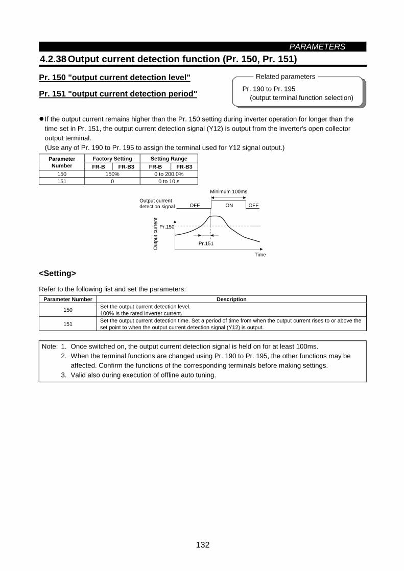
PARAMETERS
132
Pr. 190 to Pr. 195 (output terminal function selection)
Related parameters
4.2.38 Output current detection function (Pr. 150, Pr. 151)
Pr. 150 "output current detection level"
Pr. 151 "output current detection period"
If the output current remains higher than the Pr. 150 setting during inverter operation for longer than thetime set in Pr. 151, the output current detection signal (Y12) is output from the inverter's open collectoroutput terminal.(Use any of Pr. 190 to Pr. 195 to assign the terminal used for Y12 signal output.)
Factory Setting Setting RangeParameterNumber FR-B FR-B3 FR-B FR-B3
150 150% 0 to 200.0%151 0 0 to 10 s
Pr.151
Pr.150
OFF ON OFF
Minimum 100ms
Time
Output currentdetection signal
Out
put c
urre
nt
<Setting>
Refer to the following list and set the parameters:Parameter Number Description
150 Set the output current detection level.100% is the rated inverter current.
151 Set the output current detection time. Set a period of time from when the output current rises to or above theset point to when the output current detection signal (Y12) is output.
Note: 1. Once switched on, the output current detection signal is held on for at least 100ms.2. When the terminal functions are changed using Pr. 190 to Pr. 195, the other functions may be
affected. Confirm the functions of the corresponding terminals before making settings.3. Valid also during execution of offline auto tuning.
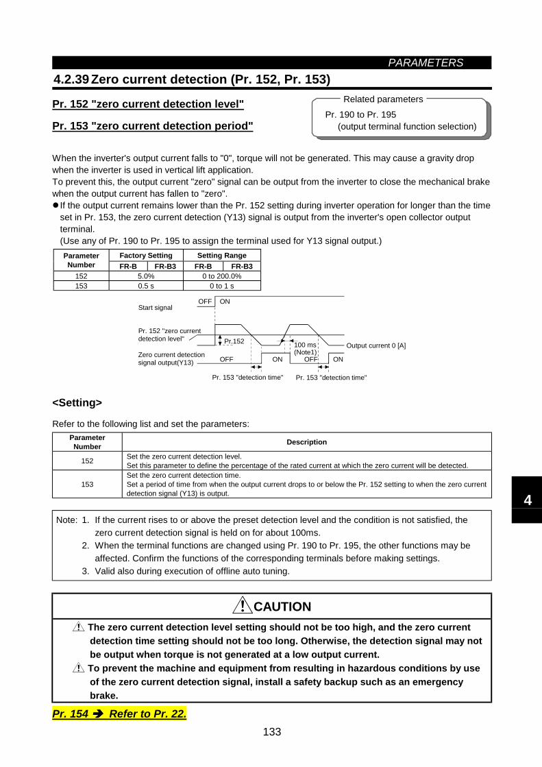
PARAMETERS
133
Pr. 190 to Pr. 195 (output terminal function selection)
Related parameters
4.2.39 Zero current detection (Pr. 152, Pr. 153)
Pr. 152 "zero current detection level"
Pr. 153 "zero current detection period"
When the inverter's output current falls to "0", torque will not be generated. This may cause a gravity dropwhen the inverter is used in vertical lift application.To prevent this, the output current "zero" signal can be output from the inverter to close the mechanical brakewhen the output current has fallen to "zero".
If the output current remains lower than the Pr. 152 setting during inverter operation for longer than the timeset in Pr. 153, the zero current detection (Y13) signal is output from the inverter's open collector outputterminal.(Use any of Pr. 190 to Pr. 195 to assign the terminal used for Y13 signal output.)
Factory Setting Setting RangeParameterNumber FR-B FR-B3 FR-B FR-B3
152 5.0% 0 to 200.0%153 0.5 s 0 to 1 s
Output current 0 [A]
OFF ON
OFF ON
Pr.152
OFF ON
100 ms(Note1)
Start signal
Pr. 152 "zero currentdetection level"
Zero current detectionsignal output(Y13)
Pr. 153 "detection time" Pr. 153 "detection time"
<Setting>
Refer to the following list and set the parameters:ParameterNumber Description
152 Set the zero current detection level.Set this parameter to define the percentage of the rated current at which the zero current will be detected.
153Set the zero current detection time.Set a period of time from when the output current drops to or below the Pr. 152 setting to when the zero currentdetection signal (Y13) is output.
Note: 1. If the current rises to or above the preset detection level and the condition is not satisfied, thezero current detection signal is held on for about 100ms.
2. When the terminal functions are changed using Pr. 190 to Pr. 195, the other functions may beaffected. Confirm the functions of the corresponding terminals before making settings.
3. Valid also during execution of offline auto tuning.
CAUTION The zero current detection level setting should not be too high, and the zero currentdetection time setting should not be too long. Otherwise, the detection signal may notbe output when torque is not generated at a low output current.
To prevent the machine and equipment from resulting in hazardous conditions by useof the zero current detection signal, install a safety backup such as an emergencybrake.
Pr. 154 Refer to Pr. 22.
4
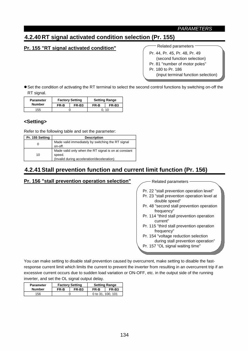
PARAMETERS
134
4.2.40 RT signal activated condition selection (Pr. 155)
Pr. 155 "RT signal activated condition"
Set the condition of activating the RT terminal to select the second control functions by switching on-off theRT signal.
Factory Setting Setting RangeParameterNumber FR-B FR-B3 FR-B FR-B3
155 0 0, 10
<Setting>
Refer to the following table and set the parameter:Pr. 155 Setting Description
0 Made valid immediately by switching the RT signalon-off.
10Made valid only when the RT signal is on at constantspeed.(Invalid during acceleration/deceleration)
4.2.41 Stall prevention function and current limit function (Pr. 156)
Pr. 156 "stall prevention operation selection"
You can make setting to disable stall prevention caused by overcurrent, make setting to disable the fast-response current limit which limits the current to prevent the inverter from resulting in an overcurrent trip if anexcessive current occurs due to sudden load variation or ON-OFF, etc. in the output side of the runninginverter, and set the OL signal output delay.
Factory Setting Setting RangeParameterNumber FR-B FR-B3 FR-B FR-B3
156 0 0 to 31, 100, 101
Pr. 44, Pr. 45, Pr. 48, Pr. 49 (second function selection)Pr. 81 "number of motor poles"Pr. 180 to Pr. 186 (input terminal function selection)
Related parameters
Pr. 22 "stall prevention operation level"Pr. 23 "stall prevention operation level at
double speed"Pr. 48 "second stall prevention operation
frequency"Pr. 114 "third stall prevention operation
current"Pr. 115 "third stall prevention operation
frequency"Pr. 154 "voltage reduction selection
during stall prevention operation"Pr. 157 "OL signal waiting time"
Related parameters
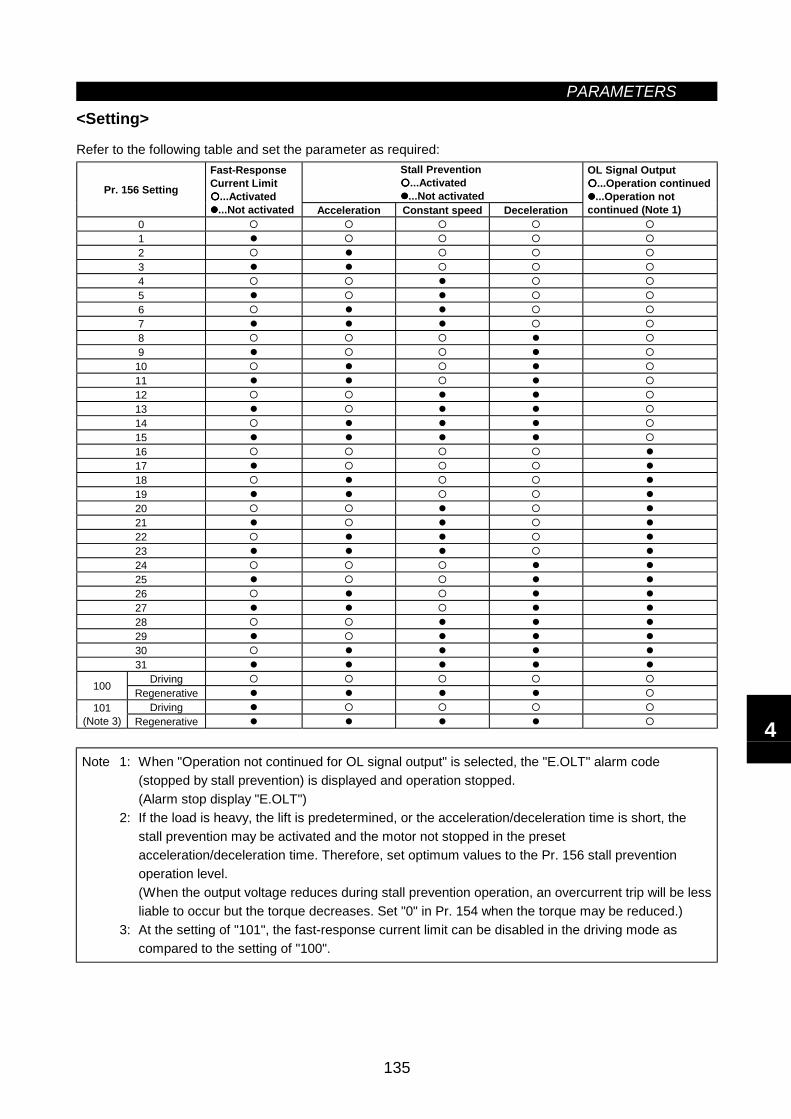
PARAMETERS
135
<Setting>
Refer to the following table and set the parameter as required:Stall Prevention
...Activated...Not activatedPr. 156 Setting
Fast-ResponseCurrent Limit
...Activated...Not activated Acceleration Constant speed Deceleration
OL Signal Output...Operation continued...Operation not
continued (Note 1)0123456789
10111213141516171819202122232425262728293031
Driving100 RegenerativeDriving101
(Note 3) Regenerative
Note 1: When "Operation not continued for OL signal output" is selected, the "E.OLT" alarm code(stopped by stall prevention) is displayed and operation stopped.(Alarm stop display "E.OLT")
2: If the load is heavy, the lift is predetermined, or the acceleration/deceleration time is short, thestall prevention may be activated and the motor not stopped in the presetacceleration/deceleration time. Therefore, set optimum values to the Pr. 156 stall preventionoperation level.(When the output voltage reduces during stall prevention operation, an overcurrent trip will be lessliable to occur but the torque decreases. Set "0" in Pr. 154 when the torque may be reduced.)
3: At the setting of "101", the fast-response current limit can be disabled in the driving mode ascompared to the setting of "100".
4
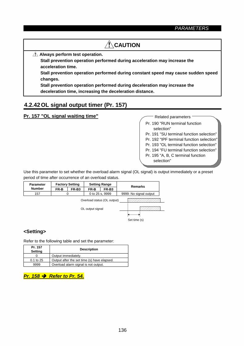
PARAMETERS
136
Pr. 190 "RUN terminal function selection"Pr. 191 "SU terminal function selection"Pr. 192 "IPF terminal function selection"Pr. 193 "OL terminal function selection"Pr. 194 "FU terminal function selection"Pr. 195 "A, B, C terminal function selection"
Related parameters
CAUTION Always perform test operation.Stall prevention operation performed during acceleration may increase theacceleration time.Stall prevention operation performed during constant speed may cause sudden speedchanges.Stall prevention operation performed during deceleration may increase thedeceleration time, increasing the deceleration distance.
4.2.42 OL signal output timer (Pr. 157)
Pr. 157 "OL signal waiting time"
Use this parameter to set whether the overload alarm signal (OL signal) is output immediately or a presetperiod of time after occurrence of an overload status.
Factory Setting Setting RangeParameterNumber FR-B FR-B3 FR-B FR-B3
Remarks
157 0 0 to 25 s, 9999 9999: No signal output
Set time (s)
Overload status (OL output)
OL output signal
<Setting>
Refer to the following table and set the parameter:Pr. 157Setting Description
0 Output immediately.0.1 to 25 Output after the set time (s) have elapsed.
9999 Overload alarm signal is not output.
Pr. 158 Refer to Pr. 54.
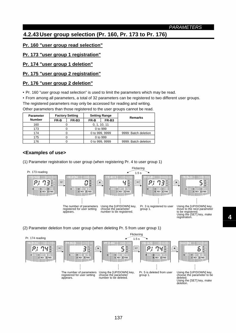
PARAMETERS
137
4.2.43 User group selection (Pr. 160, Pr. 173 to Pr. 176)
Pr. 160 "user group read selection"
Pr. 173 "user group 1 registration"
Pr. 174 "user group 1 deletion"
Pr. 175 "user group 2 registration"
Pr. 176 "user group 2 deletion"
• Pr. 160 "user group read selection" is used to limit the parameters which may be read.• From among all parameters, a total of 32 parameters can be registered to two different user groups.The registered parameters may only be accessed for reading and writing.Other parameters than those registered to the user groups cannot be read.
Factory Setting Setting RangeParameterNumber FR-B FR-B3 FR-B FR-B3
Remarks
160 0 0, 1, 10, 11173 0 0 to 999174 0 0 to 999, 9999 9999: Batch deletion175 0 0 to 999176 0 0 to 999, 9999 9999: Batch deletion
<Examples of use>
(1) Parameter registration to user group (when registering Pr. 4 to user group 1)
FR-DU04 CONTROL PANEL
Hz
MON EXT PU
AV
REV FWD
FR-DU04 CONTROL PANEL
Hz
MON EXT PU
AV
REV FWD
FR-DU04 CONTROL PANEL
Hz
MON EXT PU
AV
REV FWD
FR-DU04 CONTROL PANEL
Hz
MON EXT PU
AV
REV FWD
FR-DU04 CONTROL PANEL
Hz
MON EXT PU
AV
REV FWD
Pr. 173 reading
SET
SET
1.5 s
The number of parameters registered for user setting appears.
Using the [UP/DOWN] key, choose the parameternumber to be registered.
Pr. 3 is registered to user group 1.
Using the [UP/DOWN] key, move to the next parameter to be registered. Using the [SET] key, make registration.
.....
Flickering
.....
.....
.....
(2) Parameter deletion from user group (when deleting Pr. 5 from user group 1)
FR-DU04 CONTROL PANEL
Hz
MON EXT PU
AV
REV FWD
FR-DU04 CONTROL PANEL
Hz
MON EXT PU
AV
REV FWD
FR-DU04 CONTROL PANEL
Hz
MON EXT PU
AV
REV FWD
FR-DU04 CONTROL PANEL
Hz
MON EXT PU
AV
REV FWD
FR-DU04 CONTROL PANEL
Hz
MON EXT PU
AV
REV FWD
Pr. 174 readingSET
SET
1.5 s
The number of parameters registered for user setting appears.
Using the [UP/DOWN] key, choose the parameternumber to be deleted.
Pr. 5 is deleted from user group 1.
Using the [UP/DOWN] key, choose the parameter to be deleted. Using the [SET] key, make deletion.
.....
Flickering
.....
.....
.....
4
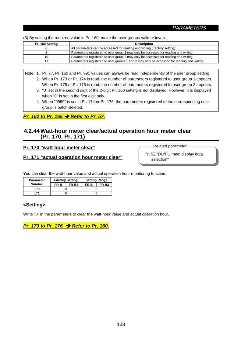
PARAMETERS
138
Pr. 52 "DU/PU main display data selection"
Related parameter
(3) By setting the required value in Pr. 160, make the user groups valid or invalid.Pr. 160 Setting Description
0 All parameters can be accessed for reading and writing (Factory setting)1 Parameters registered to user group 1 may only be accessed for reading and writing.10 Parameters registered to user group 2 may only be accessed for reading and writing.11 Parameters registered to user groups 1 and 2 may only be accessed for reading and writing.
Note: 1. Pr. 77, Pr. 160 and Pr. 991 values can always be read independently of the user group setting.2. When Pr. 173 or Pr. 174 is read, the number of parameters registered to user group 1 appears.
When Pr. 175 or Pr. 176 is read, the number of parameters registered to user group 2 appears.3. "0" set in the second digit of the 2-digit Pr. 160 setting is not displayed. However, it is displayed
when "0" is set in the first digit only.4. When "9999" is set in Pr. 174 or Pr. 176, the parameters registered to the corresponding user
group is batch-deleted.
Pr. 162 to Pr. 165 Refer to Pr. 57.
4.2.44 Watt-hour meter clear/actual operation hour meter clear(Pr. 170, Pr. 171)
Pr. 170 "watt-hour meter clear"
Pr. 171 "actual operation hour meter clear"
You can clear the watt-hour value and actual operation hour monitoring function.Factory Setting Setting RangeParameter
Number FR-B FR-B3 FR-B FR-B3170 0 0171 0 0
<Setting>
Write "0" in the parameters to clear the watt-hour value and actual operation hour.
Pr. 173 to Pr. 176 Refer to Pr. 160.
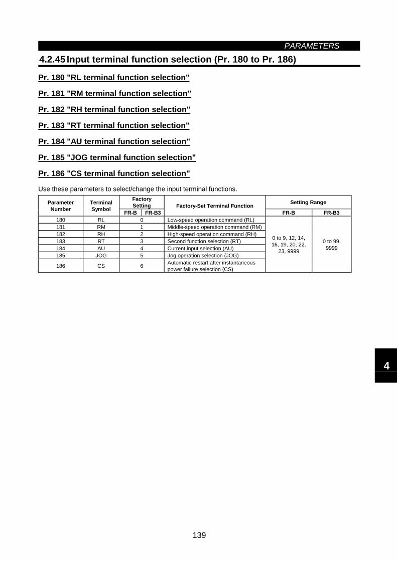
PARAMETERS
139
4.2.45 Input terminal function selection (Pr. 180 to Pr. 186)
Pr. 180 "RL terminal function selection"
Pr. 181 "RM terminal function selection"
Pr. 182 "RH terminal function selection"
Pr. 183 "RT terminal function selection"
Pr. 184 "AU terminal function selection"
Pr. 185 "JOG terminal function selection"
Pr. 186 "CS terminal function selection"
Use these parameters to select/change the input terminal functions.FactorySetting Setting RangeParameter
NumberTerminalSymbol FR-B FR-B3
Factory-Set Terminal FunctionFR-B FR-B3
180 RL 0 Low-speed operation command (RL)181 RM 1 Middle-speed operation command (RM)182 RH 2 High-speed operation command (RH)183 RT 3 Second function selection (RT)184 AU 4 Current input selection (AU)185 JOG 5 Jog operation selection (JOG)
186 CS 6 Automatic restart after instantaneouspower failure selection (CS)
0 to 9, 12, 14,16, 19, 20, 22,
23, 9999
0 to 99,9999
4
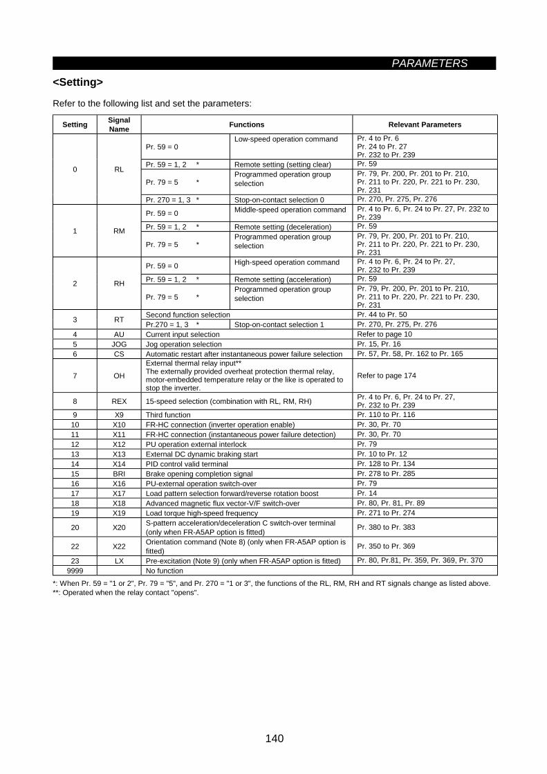
PARAMETERS
140
<Setting>
Refer to the following list and set the parameters:
Setting SignalName Functions Relevant Parameters
Pr. 59 = 0Low-speed operation command Pr. 4 to Pr. 6
Pr. 24 to Pr. 27Pr. 232 to Pr. 239
Pr. 59 = 1, 2 * Remote setting (setting clear) Pr. 59
Pr. 79 = 5 *Programmed operation groupselection
Pr. 79, Pr. 200, Pr. 201 to Pr. 210,Pr. 211 to Pr. 220, Pr. 221 to Pr. 230,Pr. 231
0 RL
Pr. 270 = 1, 3 * Stop-on-contact selection 0 Pr. 270, Pr. 275, Pr. 276
Pr. 59 = 0 Middle-speed operation command Pr. 4 to Pr. 6, Pr. 24 to Pr. 27, Pr. 232 toPr. 239
Pr. 59 = 1, 2 * Remote setting (deceleration) Pr. 591 RM
Pr. 79 = 5 *Programmed operation groupselection
Pr. 79, Pr. 200, Pr. 201 to Pr. 210,Pr. 211 to Pr. 220, Pr. 221 to Pr. 230,Pr. 231
Pr. 59 = 0 High-speed operation command Pr. 4 to Pr. 6, Pr. 24 to Pr. 27,Pr. 232 to Pr. 239
Pr. 59 = 1, 2 * Remote setting (acceleration) Pr. 592 RH
Pr. 79 = 5 *Programmed operation groupselection
Pr. 79, Pr. 200, Pr. 201 to Pr. 210,Pr. 211 to Pr. 220, Pr. 221 to Pr. 230,Pr. 231
Second function selection Pr. 44 to Pr. 503 RT Pr.270 = 1, 3 * Stop-on-contact selection 1 Pr. 270, Pr. 275, Pr. 2764 AU Current input selection Refer to page 105 JOG Jog operation selection Pr. 15, Pr. 166 CS Automatic restart after instantaneous power failure selection Pr. 57, Pr. 58, Pr. 162 to Pr. 165
7 OH
External thermal relay input**The externally provided overheat protection thermal relay,motor-embedded temperature relay or the like is operated tostop the inverter.
Refer to page 174
8 REX 15-speed selection (combination with RL, RM, RH) Pr. 4 to Pr. 6, Pr. 24 to Pr. 27,Pr. 232 to Pr. 239
9 X9 Third function Pr. 110 to Pr. 11610 X10 FR-HC connection (inverter operation enable) Pr. 30, Pr. 7011 X11 FR-HC connection (instantaneous power failure detection) Pr. 30, Pr. 7012 X12 PU operation external interlock Pr. 7913 X13 External DC dynamic braking start Pr. 10 to Pr. 1214 X14 PID control valid terminal Pr. 128 to Pr. 13415 BRI Brake opening completion signal Pr. 278 to Pr. 28516 X16 PU-external operation switch-over Pr. 7917 X17 Load pattern selection forward/reverse rotation boost Pr. 1418 X18 Advanced magnetic flux vector-V/F switch-over Pr. 80, Pr. 81, Pr. 8919 X19 Load torque high-speed frequency Pr. 271 to Pr. 274
20 X20 S-pattern acceleration/deceleration C switch-over terminal(only when FR-A5AP option is fitted) Pr. 380 to Pr. 383
22 X22 Orientation command (Note 8) (only when FR-A5AP option isfitted) Pr. 350 to Pr. 369
23 LX Pre-excitation (Note 9) (only when FR-A5AP option is fitted) Pr. 80, Pr.81, Pr. 359, Pr. 369, Pr. 3709999 No function
*: When Pr. 59 = "1 or 2", Pr. 79 = "5", and Pr. 270 = "1 or 3", the functions of the RL, RM, RH and RT signals change as listed above.**: Operated when the relay contact "opens".
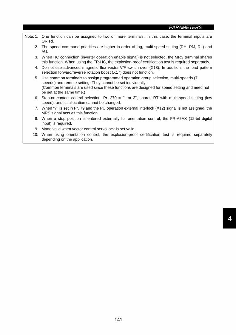
PARAMETERS
141
Note: 1. One function can be assigned to two or more terminals. In this case, the terminal inputs areOR’ed.
2. The speed command priorities are higher in order of jog, multi-speed setting (RH, RM, RL) andAU.
3. When HC connection (inverter operation enable signal) is not selected, the MRS terminal sharesthis function. When using the FR-HC, the explosion-proof certification test is required separately.
4. Do not use advanced magnetic flux vector-V/F switch-over (X18). In addition, the load patternselection forward/reverse rotation boost (X17) does not function.
5. Use common terminals to assign programmed operation group selection, multi-speeds (7speeds) and remote setting. They cannot be set individually.(Common terminals are used since these functions are designed for speed setting and need notbe set at the same time.)
6. Stop-on-contact control selection, Pr. 270 = "1 or 3", shares RT with multi-speed setting (lowspeed), and its allocation cannot be changed.
7. When "7" is set in Pr. 79 and the PU operation external interlock (X12) signal is not assigned, theMRS signal acts as this function.
8. When a stop position is entered externally for orientation control, the FR-A5AX (12-bit digitalinput) is required.
9. Made valid when vector control servo lock is set valid.10. When using orientation control, the explosion-proof certification test is required separately
depending on the application.
4
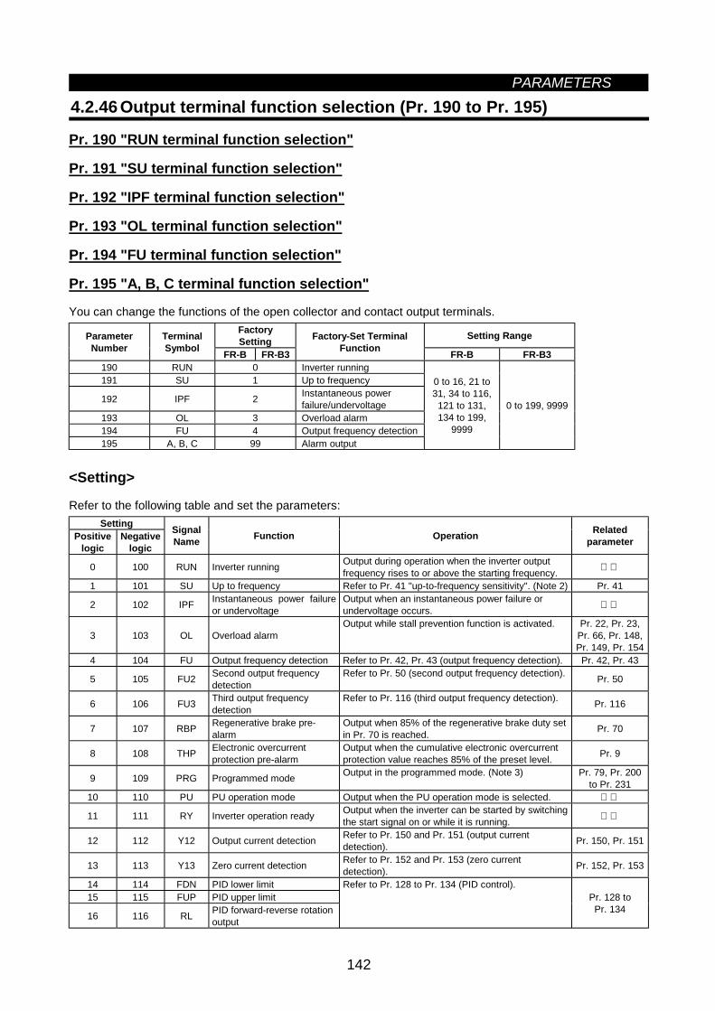
PARAMETERS
142
4.2.46 Output terminal function selection (Pr. 190 to Pr. 195)
Pr. 190 "RUN terminal function selection"
Pr. 191 "SU terminal function selection"
Pr. 192 "IPF terminal function selection"
Pr. 193 "OL terminal function selection"
Pr. 194 "FU terminal function selection"
Pr. 195 "A, B, C terminal function selection"
You can change the functions of the open collector and contact output terminals.FactorySetting Setting RangeParameter
NumberTerminalSymbol FR-B FR-B3
Factory-Set TerminalFunction FR-B FR-B3
190 RUN 0 Inverter running191 SU 1 Up to frequency
192 IPF 2 Instantaneous powerfailure/undervoltage
193 OL 3 Overload alarm194 FU 4 Output frequency detection195 A, B, C 99 Alarm output
0 to 16, 21 to31, 34 to 116,
121 to 131,134 to 199,
9999
0 to 199, 9999
<Setting>
Refer to the following table and set the parameters:Setting
Positivelogic
Negativelogic
SignalName Function Operation Related
parameter
0 100 RUN Inverter running Output during operation when the inverter outputfrequency rises to or above the starting frequency.
1 101 SU Up to frequency Refer to Pr. 41 "up-to-frequency sensitivity". (Note 2) Pr. 41
2 102 IPF Instantaneous power failureor undervoltage
Output when an instantaneous power failure orundervoltage occurs.
3 103 OL Overload alarmOutput while stall prevention function is activated. Pr. 22, Pr. 23,
Pr. 66, Pr. 148,Pr. 149, Pr. 154
4 104 FU Output frequency detection Refer to Pr. 42, Pr. 43 (output frequency detection). Pr. 42, Pr. 43
5 105 FU2 Second output frequencydetection
Refer to Pr. 50 (second output frequency detection). Pr. 50
6 106 FU3 Third output frequencydetection
Refer to Pr. 116 (third output frequency detection). Pr. 116
7 107 RBP Regenerative brake pre-alarm
Output when 85% of the regenerative brake duty setin Pr. 70 is reached. Pr. 70
8 108 THP Electronic overcurrentprotection pre-alarm
Output when the cumulative electronic overcurrentprotection value reaches 85% of the preset level. Pr. 9
9 109 PRG Programmed mode Output in the programmed mode. (Note 3) Pr. 79, Pr. 200to Pr. 231
10 110 PU PU operation mode Output when the PU operation mode is selected.
11 111 RY Inverter operation ready Output when the inverter can be started by switchingthe start signal on or while it is running.
12 112 Y12 Output current detection Refer to Pr. 150 and Pr. 151 (output currentdetection). Pr. 150, Pr. 151
13 113 Y13 Zero current detection Refer to Pr. 152 and Pr. 153 (zero currentdetection). Pr. 152, Pr. 153
14 114 FDN PID lower limit15 115 FUP PID upper limit
16 116 RL PID forward-reverse rotationoutput
Refer to Pr. 128 to Pr. 134 (PID control).Pr. 128 toPr. 134
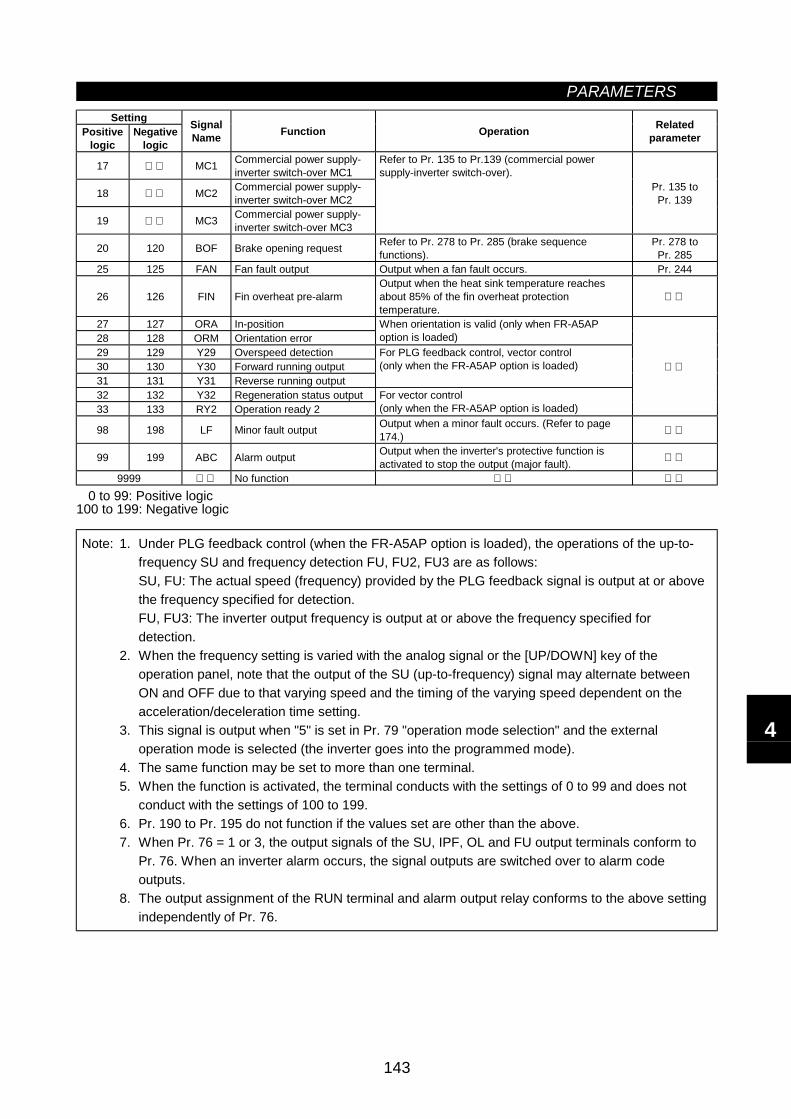
PARAMETERS
143
SettingPositive
logicNegative
logic
SignalName Function Operation Related
parameter
17 MC1 Commercial power supply-inverter switch-over MC1
18 MC2 Commercial power supply-inverter switch-over MC2
19 MC3 Commercial power supply-inverter switch-over MC3
Refer to Pr. 135 to Pr.139 (commercial powersupply-inverter switch-over).
Pr. 135 toPr. 139
20 120 BOF Brake opening request Refer to Pr. 278 to Pr. 285 (brake sequencefunctions).
Pr. 278 toPr. 285
25 125 FAN Fan fault output Output when a fan fault occurs. Pr. 244
26 126 FIN Fin overheat pre-alarmOutput when the heat sink temperature reachesabout 85% of the fin overheat protectiontemperature.
27 127 ORA In-position28 128 ORM Orientation error
When orientation is valid (only when FR-A5APoption is loaded)
29 129 Y29 Overspeed detection30 130 Y30 Forward running output31 131 Y31 Reverse running output
For PLG feedback control, vector control(only when the FR-A5AP option is loaded)
32 132 Y32 Regeneration status output33 133 RY2 Operation ready 2
For vector control(only when the FR-A5AP option is loaded)
98 198 LF Minor fault output Output when a minor fault occurs. (Refer to page174.)
99 199 ABC Alarm output Output when the inverter's protective function isactivated to stop the output (major fault).
9999 No function
0 to 99: Positive logic100 to 199: Negative logic
Note: 1. Under PLG feedback control (when the FR-A5AP option is loaded), the operations of the up-to-frequency SU and frequency detection FU, FU2, FU3 are as follows:SU, FU: The actual speed (frequency) provided by the PLG feedback signal is output at or abovethe frequency specified for detection.FU, FU3: The inverter output frequency is output at or above the frequency specified fordetection.
2. When the frequency setting is varied with the analog signal or the [UP/DOWN] key of theoperation panel, note that the output of the SU (up-to-frequency) signal may alternate betweenON and OFF due to that varying speed and the timing of the varying speed dependent on theacceleration/deceleration time setting.
3. This signal is output when "5" is set in Pr. 79 "operation mode selection" and the externaloperation mode is selected (the inverter goes into the programmed mode).
4. The same function may be set to more than one terminal.5. When the function is activated, the terminal conducts with the settings of 0 to 99 and does not
conduct with the settings of 100 to 199.6. Pr. 190 to Pr. 195 do not function if the values set are other than the above.7. When Pr. 76 = 1 or 3, the output signals of the SU, IPF, OL and FU output terminals conform to
Pr. 76. When an inverter alarm occurs, the signal outputs are switched over to alarm codeoutputs.
8. The output assignment of the RUN terminal and alarm output relay conforms to the above settingindependently of Pr. 76.
4
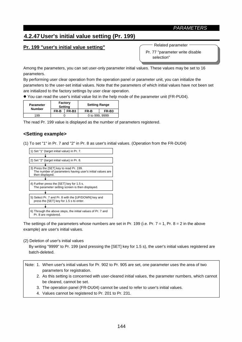
PARAMETERS
144
Pr. 77 "parameter write disable selection"
Related parameter
4.2.47 User's initial value setting (Pr. 199)
Pr. 199 "user's initial value setting"
Among the parameters, you can set user-only parameter initial values. These values may be set to 16parameters.By performing user clear operation from the operation panel or parameter unit, you can initialize theparameters to the user-set initial values. Note that the parameters of which initial values have not been setare initialized to the factory settings by user clear operation.
You can read the user's initial value list in the help mode of the parameter unit (FR-PU04).FactorySetting Setting RangeParameter
Number FR-B FR-B3 FR-B FR-B3199 0 0 to 999, 9999
The read Pr. 199 value is displayed as the number of parameters registered.
<Setting example>
(1) To set "1" in Pr. 7 and "2" in Pr. 8 as user's initial values. (Operation from the FR-DU04)
6) Through the above steps, the initial values of Pr. 7 and Pr. 8 are registered.
1) Set "1" (target initial value) in Pr. 7.
2) Set "2" (target initial value) in Pr. 8.
3) Press the [SET] key to read Pr. 199. The number of parameters having user's initial values are then displayed.
4) Further press the [SET] key for 1.5 s. The parameter setting screen is then displayed.
5) Select Pr. 7 and Pr. 8 with the [UP/DOWN] key and press the [SET] key for 1.5 s to enter.
The settings of the parameters whose numbers are set in Pr. 199 (i.e. Pr. 7 = 1, Pr. 8 = 2 in the aboveexample) are user's initial values.
(2) Deletion of user's initial valuesBy writing "9999" to Pr. 199 (and pressing the [SET] key for 1.5 s), the user's initial values registered arebatch-deleted.
Note: 1. When user's initial values for Pr. 902 to Pr. 905 are set, one parameter uses the area of twoparameters for registration.
2. As this setting is concerned with user-cleared initial values, the parameter numbers, which cannotbe cleared, cannot be set.
3. The operation panel (FR-DU04) cannot be used to refer to user's initial values.4. Values cannot be registered to Pr. 201 to Pr. 231.
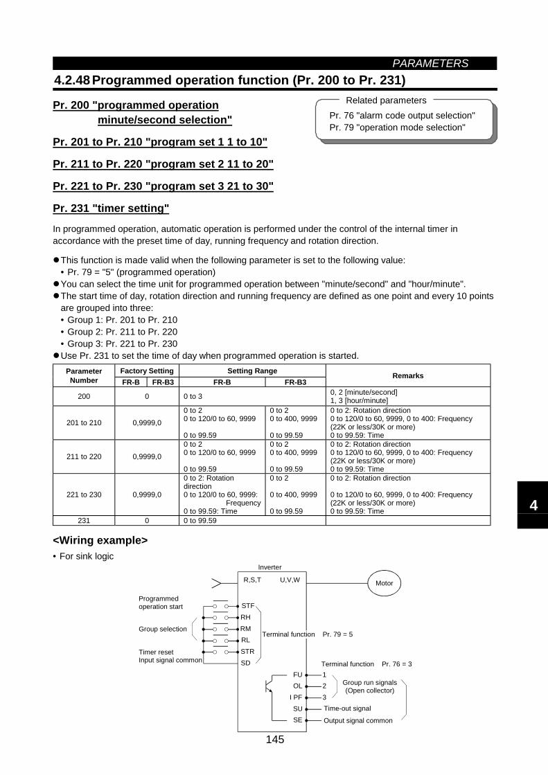
PARAMETERS
145
4.2.48 Programmed operation function (Pr. 200 to Pr. 231)
Pr. 200 "programmed operationminute/second selection"
Pr. 201 to Pr. 210 "program set 1 1 to 10"
Pr. 211 to Pr. 220 "program set 2 11 to 20"
Pr. 221 to Pr. 230 "program set 3 21 to 30"
Pr. 231 "timer setting"
In programmed operation, automatic operation is performed under the control of the internal timer inaccordance with the preset time of day, running frequency and rotation direction.
This function is made valid when the following parameter is set to the following value:• Pr. 79 = "5" (programmed operation)You can select the time unit for programmed operation between "minute/second" and "hour/minute".The start time of day, rotation direction and running frequency are defined as one point and every 10 pointsare grouped into three:• Group 1: Pr. 201 to Pr. 210• Group 2: Pr. 211 to Pr. 220• Group 3: Pr. 221 to Pr. 230Use Pr. 231 to set the time of day when programmed operation is started.
Factory Setting Setting RangeParameterNumber FR-B FR-B3 FR-B FR-B3
Remarks
200 0 0 to 3 0, 2 [minute/second]1, 3 [hour/minute]
201 to 210 0,9999,00 to 20 to 120/0 to 60, 9999
0 to 99.59
0 to 20 to 400, 9999
0 to 99.59
0 to 2: Rotation direction0 to 120/0 to 60, 9999, 0 to 400: Frequency(22K or less/30K or more)0 to 99.59: Time
211 to 220 0,9999,00 to 20 to 120/0 to 60, 9999
0 to 99.59
0 to 20 to 400, 9999
0 to 99.59
0 to 2: Rotation direction0 to 120/0 to 60, 9999, 0 to 400: Frequency(22K or less/30K or more)0 to 99.59: Time
221 to 230 0,9999,0
0 to 2: Rotationdirection0 to 120/0 to 60, 9999:
Frequency0 to 99.59: Time
0 to 2
0 to 400, 9999
0 to 99.59
0 to 2: Rotation direction
0 to 120/0 to 60, 9999, 0 to 400: Frequency(22K or less/30K or more)0 to 99.59: Time
231 0 0 to 99.59
<Wiring example>• For sink logic
STFRHRMRLSTRSD
FUOLPFSUSE
I
1 2 3
U,V,W
Output signal common
Programmed operation start
Group selection
Timer resetInput signal common
Inverter
Motor
Terminal function Pr. 79 = 5
Terminal function Pr. 76 = 3
Group run signals(Open collector)
Time-out signal
R,S,T
Pr. 76 "alarm code output selection"Pr. 79 "operation mode selection"
Related parameters
4
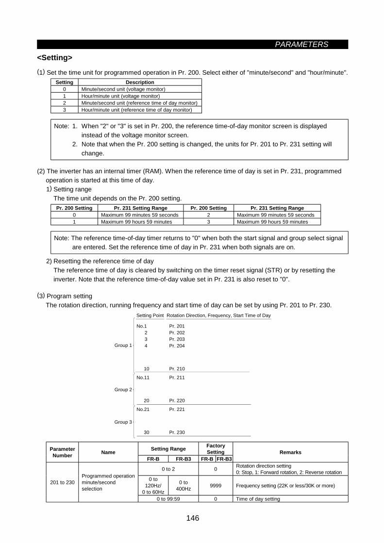
PARAMETERS
146
<Setting>(1) Set the time unit for programmed operation in Pr. 200. Select either of "minute/second" and "hour/minute".
Setting Description0 Minute/second unit (voltage monitor)1 Hour/minute unit (voltage monitor)2 Minute/second unit (reference time of day monitor)3 Hour/minute unit (reference time of day monitor)
Note: 1. When "2" or "3" is set in Pr. 200, the reference time-of-day monitor screen is displayedinstead of the voltage monitor screen.
2. Note that when the Pr. 200 setting is changed, the units for Pr. 201 to Pr. 231 setting willchange.
(2) The inverter has an internal timer (RAM). When the reference time of day is set in Pr. 231, programmedoperation is started at this time of day.1) Setting range
The time unit depends on the Pr. 200 setting.Pr. 200 Setting Pr. 231 Setting Range Pr. 200 Setting Pr. 231 Setting Range
0 Maximum 99 minutes 59 seconds 2 Maximum 99 minutes 59 seconds1 Maximum 99 hours 59 minutes 3 Maximum 99 hours 59 minutes
Note: The reference time-of-day timer returns to "0" when both the start signal and group select signalare entered. Set the reference time of day in Pr. 231 when both signals are on.
2) Resetting the reference time of dayThe reference time of day is cleared by switching on the timer reset signal (STR) or by resetting theinverter. Note that the reference time-of-day value set in Pr. 231 is also reset to "0".
(3) Program settingThe rotation direction, running frequency and start time of day can be set by using Pr. 201 to Pr. 230.
No.1 Pr. 201 2 Pr. 202 3 Pr. 203 4 Pr. 204
10 Pr. 210
No.11 Pr. 211
20 Pr. 220
No.21 Pr. 221
30 Pr. 230
Setting Point Rotation Direction, Frequency, Start Time of Day
Group 3
Group 1
Group 2
Setting Range FactorySettingParameter
Number NameFR-B FR-B3 FR-B FR-B3
Remarks
0 to 2 0 Rotation direction setting0: Stop, 1: Forward rotation, 2: Reverse rotation
0 to120Hz/
0 to 60Hz
0 to400Hz 9999 Frequency setting (22K or less/30K or more)201 to 230
Programmed operationminute/secondselection
0 to 99:59 0 Time of day setting
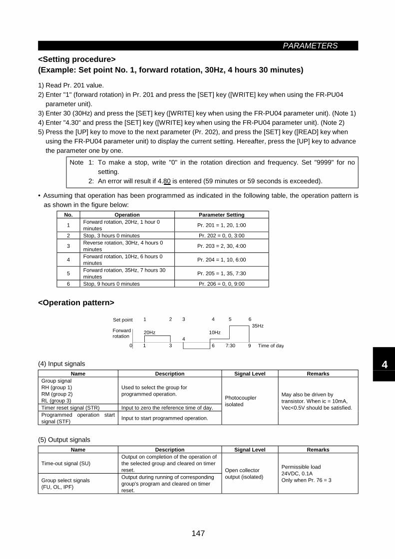
PARAMETERS
147
<Setting procedure>(Example: Set point No. 1, forward rotation, 30Hz, 4 hours 30 minutes)
1) Read Pr. 201 value.2) Enter "1" (forward rotation) in Pr. 201 and press the [SET] key ([WRITE] key when using the FR-PU04
parameter unit).3) Enter 30 (30Hz) and press the [SET] key ([WRITE] key when using the FR-PU04 parameter unit). (Note 1)4) Enter "4.30" and press the [SET] key ([WRITE] key when using the FR-PU04 parameter unit). (Note 2)5) Press the [UP] key to move to the next parameter (Pr. 202), and press the [SET] key ([READ] key when
using the FR-PU04 parameter unit) to display the current setting. Hereafter, press the [UP] key to advancethe parameter one by one.
Note 1: To make a stop, write "0" in the rotation direction and frequency. Set "9999" for nosetting.
2: An error will result if 4.80 is entered (59 minutes or 59 seconds is exceeded).
• Assuming that operation has been programmed as indicated in the following table, the operation pattern isas shown in the figure below:
No. Operation Parameter Setting
1 Forward rotation, 20Hz, 1 hour 0minutes Pr. 201 = 1, 20, 1:00
2 Stop, 3 hours 0 minutes Pr. 202 = 0, 0, 3:00
3 Reverse rotation, 30Hz, 4 hours 0minutes Pr. 203 = 2, 30, 4:00
4 Forward rotation, 10Hz, 6 hours 0minutes Pr. 204 = 1, 10, 6:00
5 Forward rotation, 35Hz, 7 hours 30minutes Pr. 205 = 1, 35, 7:30
6 Stop, 9 hours 0 minutes Pr. 206 = 0, 0, 9:00
<Operation pattern>
20Hz
0 1 34
6 9
10Hz
32 4 5 6
7:30
35Hz
Time of day
Set point
Forwardrotation
1
(4) Input signalsName Description Signal Level Remarks
Group signalRH (group 1)RM (group 2)RL (group 3)
Used to select the group forprogrammed operation.
Timer reset signal (STR) Input to zero the reference time of day.Programmed operation startsignal (STF) Input to start programmed operation.
Photocouplerisolated
May also be driven bytransistor. When ic = 10mA,Vec<0.5V should be satisfied.
(5) Output signalsName Description Signal Level Remarks
Time-out signal (SU)Output on completion of the operation ofthe selected group and cleared on timerreset.
Group select signals(FU, OL, IPF)
Output during running of correspondinggroup's program and cleared on timerreset.
Open collectoroutput (isolated)
Permissible load24VDC, 0.1AOnly when Pr. 76 = 3
4
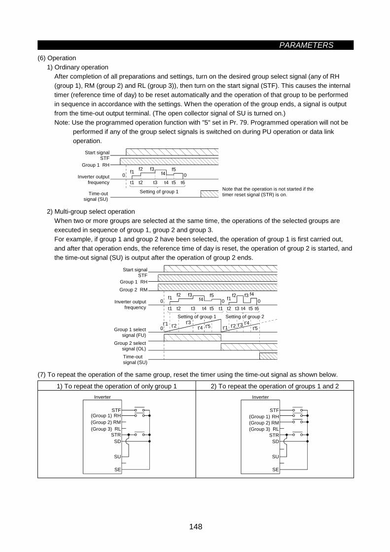
PARAMETERS
148
(6) Operation1) Ordinary operation
After completion of all preparations and settings, turn on the desired group select signal (any of RH(group 1), RM (group 2) and RL (group 3)), then turn on the start signal (STF). This causes the internaltimer (reference time of day) to be reset automatically and the operation of that group to be performedin sequence in accordance with the settings. When the operation of the group ends, a signal is outputfrom the time-out output terminal. (The open collector signal of SU is turned on.)Note: Use the programmed operation function with "5" set in Pr. 79. Programmed operation will not be
performed if any of the group select signals is switched on during PU operation or data linkoperation.
t1 t2 t3 t4 t5 t6
f1 f2 f3f4
f50 0
Note that the operation is not started if thetimer reset signal (STR) is on.
Start signalSTF
Group 1 RH
Inverter outputfrequency
Time-out signal (SU)
Setting of group 1
2) Multi-group select operationWhen two or more groups are selected at the same time, the operations of the selected groups areexecuted in sequence of group 1, group 2 and group 3.For example, if group 1 and group 2 have been selected, the operation of group 1 is first carried out,and after that operation ends, the reference time of day is reset, the operation of group 2 is started, andthe time-out signal (SU) is output after the operation of group 2 ends.
t1 t2 t3 t4 t5 t1 t2 t3 t4 t5 t6
f1 f2 f3f4
f5 f1 f2 f3 f40 0 0
0t'1 t'2 t'3
t'4 t'5 t'1 t'2 t'3 t'4t'5
Time-out signal (SU)
Start signalSTF
Group 1 RHGroup 2 RM
Inverter output frequency
Group 1 select signal (FU)
Group 2 select signal (OL)
Setting of group 1 Setting of group 2
(7) To repeat the operation of the same group, reset the timer using the time-out signal as shown below.
1) To repeat the operation of only group 1 2) To repeat the operation of groups 1 and 2
(Group 2)
STF
STR
SU
SD
SE
Inverter
(Group 3)
(Group 1) RHRMRL
(Group 2)
STF
STR
SU
SD
SE
Inverter
(Group 3)
(Group 1) RHRMRL
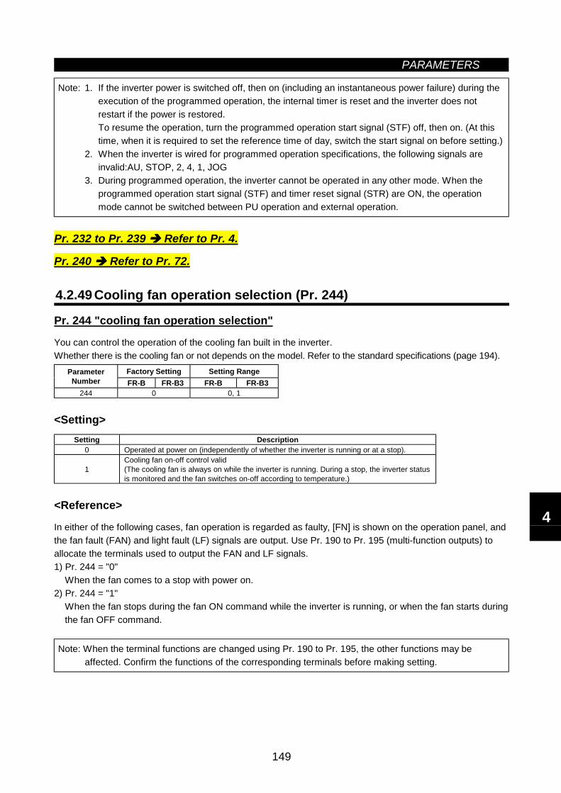
PARAMETERS
149
Note: 1. If the inverter power is switched off, then on (including an instantaneous power failure) during theexecution of the programmed operation, the internal timer is reset and the inverter does notrestart if the power is restored.To resume the operation, turn the programmed operation start signal (STF) off, then on. (At thistime, when it is required to set the reference time of day, switch the start signal on before setting.)
2. When the inverter is wired for programmed operation specifications, the following signals areinvalid:AU, STOP, 2, 4, 1, JOG
3. During programmed operation, the inverter cannot be operated in any other mode. When theprogrammed operation start signal (STF) and timer reset signal (STR) are ON, the operationmode cannot be switched between PU operation and external operation.
Pr. 232 to Pr. 239 Refer to Pr. 4.
Pr. 240 Refer to Pr. 72.
4.2.49 Cooling fan operation selection (Pr. 244)
Pr. 244 "cooling fan operation selection"
You can control the operation of the cooling fan built in the inverter.Whether there is the cooling fan or not depends on the model. Refer to the standard specifications (page 194).
Factory Setting Setting RangeParameterNumber FR-B FR-B3 FR-B FR-B3
244 0 0, 1
<Setting>Setting Description
0 Operated at power on (independently of whether the inverter is running or at a stop).
1Cooling fan on-off control valid(The cooling fan is always on while the inverter is running. During a stop, the inverter statusis monitored and the fan switches on-off according to temperature.)
<Reference>
In either of the following cases, fan operation is regarded as faulty, [FN] is shown on the operation panel, andthe fan fault (FAN) and light fault (LF) signals are output. Use Pr. 190 to Pr. 195 (multi-function outputs) toallocate the terminals used to output the FAN and LF signals.1) Pr. 244 = "0"
When the fan comes to a stop with power on.2) Pr. 244 = "1"
When the fan stops during the fan ON command while the inverter is running, or when the fan starts duringthe fan OFF command.
Note: When the terminal functions are changed using Pr. 190 to Pr. 195, the other functions may beaffected. Confirm the functions of the corresponding terminals before making setting.
4
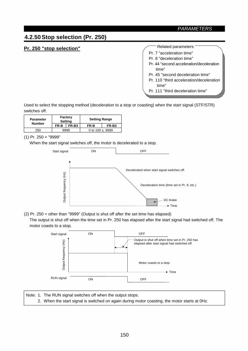
PARAMETERS
150
Pr. 7 "acceleration time"Pr. 8 "deceleration time"Pr. 44 "second acceleration/deceleration time"Pr. 45 "second deceleration time"Pr. 110 "third acceleration/deceleration time"Pr. 111 "third deceleration time"
Related parameters
4.2.50 Stop selection (Pr. 250)
Pr. 250 "stop selection"
Used to select the stopping method (deceleration to a stop or coasting) when the start signal (STF/STR)switches off.
FactorySetting Setting RangeParameter
Number FR-B FR-B3 FR-B FR-B3250 9999 0 to 100 s, 9999
(1) Pr. 250 = "9999"When the start signal switches off, the motor is decelerated to a stop.
Time
ON OFF
DC brake
Start signal
Out
put f
requ
ency
(Hz)
Decelerated when start signal switches off.
Deceleration time (time set in Pr. 8, etc.)
(2) Pr. 250 = other than "9999" (Output is shut off after the set time has elapsed)The output is shut off when the time set in Pr. 250 has elapsed after the start signal had switched off. Themotor coasts to a stop.
OFF
OFF
Start signal
RUN signal
Time
Output is shut off when time set in Pr. 250 haselapsed after start signal had switched off.
Motor coasts to a stop.
ON
ON
Out
put f
requ
ency
(Hz)
Note: 1. The RUN signal switches off when the output stops.2. When the start signal is switched on again during motor coasting, the motor starts at 0Hz.
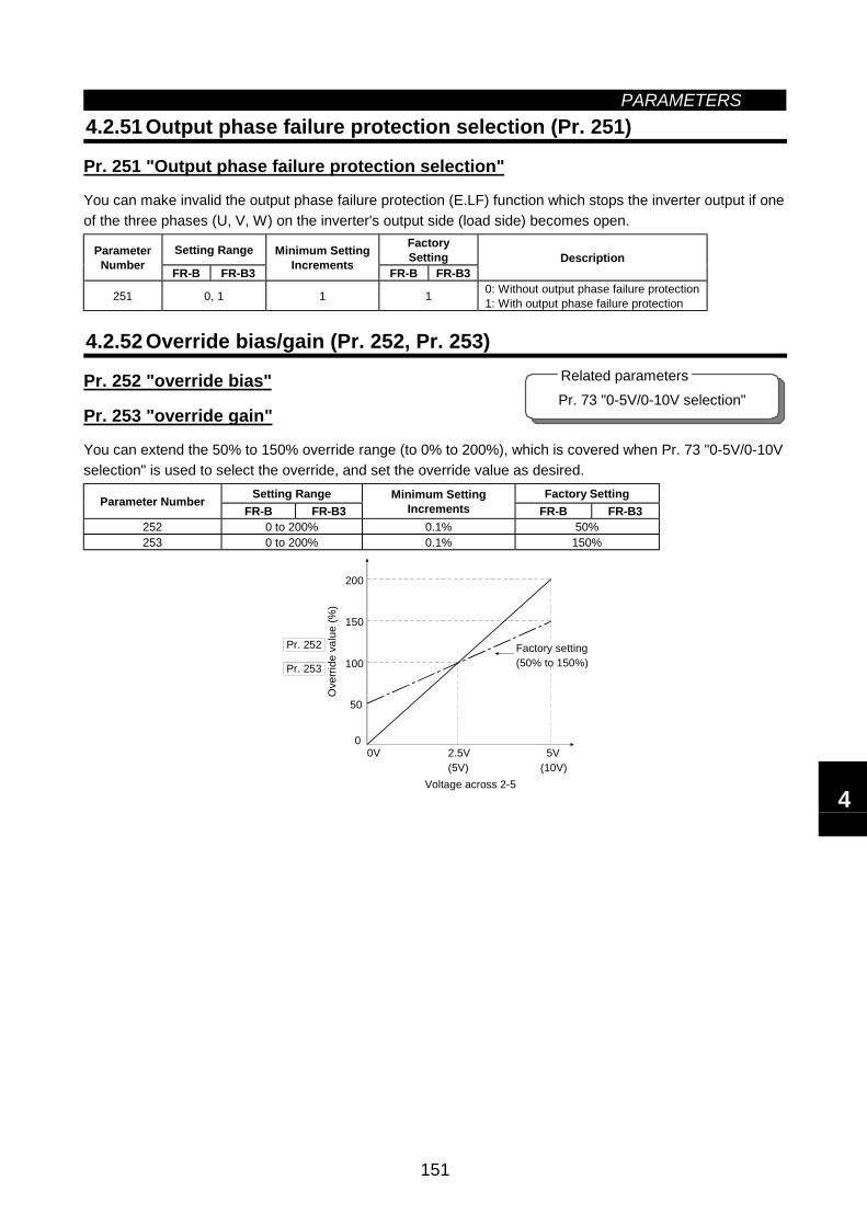
PARAMETERS
151
4.2.51 Output phase failure protection selection (Pr. 251)
Pr. 251 "Output phase failure protection selection"
You can make invalid the output phase failure protection (E.LF) function which stops the inverter output if oneof the three phases (U, V, W) on the inverter's output side (load side) becomes open.
Setting Range FactorySettingParameter
Number FR-B FR-B3
Minimum SettingIncrements FR-B FR-B3
Description
251 0, 1 1 1 0: Without output phase failure protection1: With output phase failure protection
4.2.52 Override bias/gain (Pr. 252, Pr. 253)
Pr. 252 "override bias"
Pr. 253 "override gain"
You can extend the 50% to 150% override range (to 0% to 200%), which is covered when Pr. 73 "0-5V/0-10Vselection" is used to select the override, and set the override value as desired.
Setting Range Factory SettingParameter NumberFR-B FR-B3
Minimum SettingIncrements FR-B FR-B3
252 0 to 200% 0.1% 50%253 0 to 200% 0.1% 150%
Ove
rride
val
ue (%
)
Pr. 252
0V 2.5V(5V)
5V(10V)
0
50
100
150
200
Factory setting(50% to 150%)
Voltage across 2-5
Pr. 253
Pr. 73 "0-5V/0-10V selection"Related parameters
4
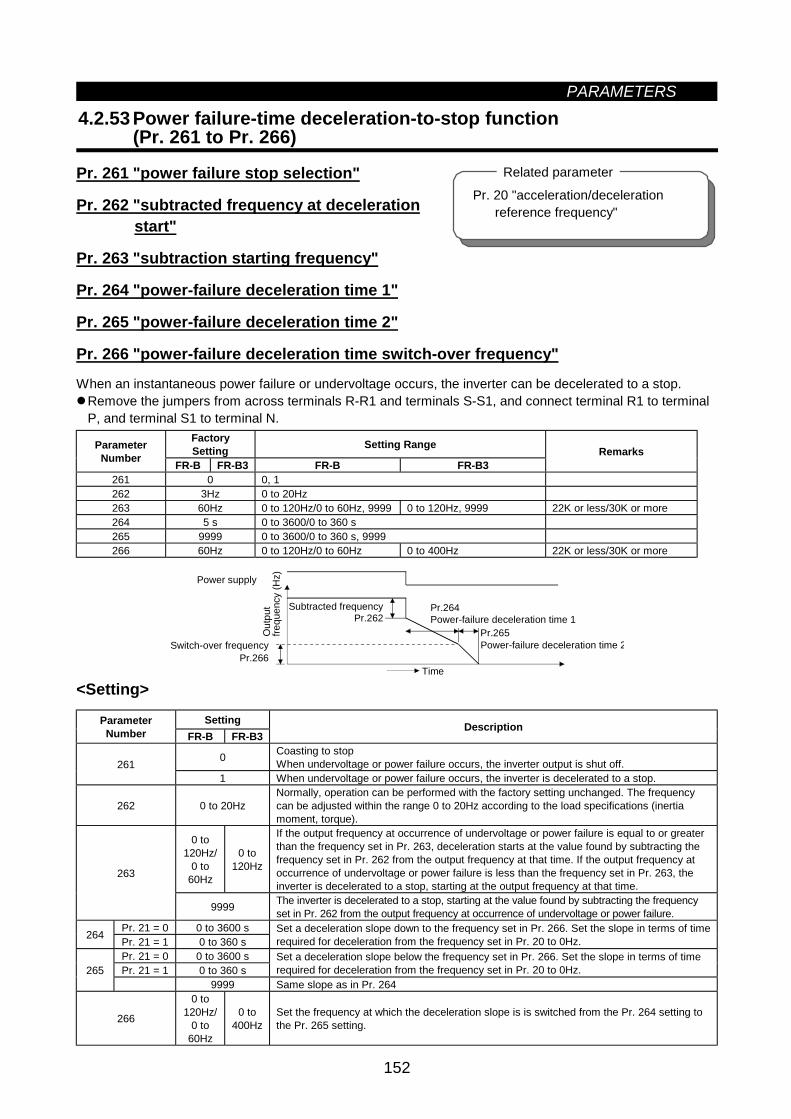
PARAMETERS
152
4.2.53 Power failure-time deceleration-to-stop function(Pr. 261 to Pr. 266)
Pr. 261 "power failure stop selection"
Pr. 262 "subtracted frequency at deceleration start"
Pr. 263 "subtraction starting frequency"
Pr. 264 "power-failure deceleration time 1"
Pr. 265 "power-failure deceleration time 2"
Pr. 266 "power-failure deceleration time switch-over frequency"
When an instantaneous power failure or undervoltage occurs, the inverter can be decelerated to a stop.Remove the jumpers from across terminals R-R1 and terminals S-S1, and connect terminal R1 to terminalP, and terminal S1 to terminal N.
FactorySetting Setting RangeParameter
Number FR-B FR-B3 FR-B FR-B3Remarks
261 0 0, 1262 3Hz 0 to 20Hz263 60Hz 0 to 120Hz/0 to 60Hz, 9999 0 to 120Hz, 9999 22K or less/30K or more264 5 s 0 to 3600/0 to 360 s265 9999 0 to 3600/0 to 360 s, 9999266 60Hz 0 to 120Hz/0 to 60Hz 0 to 400Hz 22K or less/30K or more
Pr.262Pr.264
Pr.265
Pr.266Time
Power supply
Out
put
frequ
ency
(Hz)
Switch-over frequency
Subtracted frequencyPower-failure deceleration time 1
Power-failure deceleration time 2
<Setting>
SettingParameterNumber FR-B FR-B3
Description
0 Coasting to stopWhen undervoltage or power failure occurs, the inverter output is shut off.261
1 When undervoltage or power failure occurs, the inverter is decelerated to a stop.
262 0 to 20HzNormally, operation can be performed with the factory setting unchanged. The frequencycan be adjusted within the range 0 to 20Hz according to the load specifications (inertiamoment, torque).
0 to120Hz/
0 to60Hz
0 to120Hz
If the output frequency at occurrence of undervoltage or power failure is equal to or greaterthan the frequency set in Pr. 263, deceleration starts at the value found by subtracting thefrequency set in Pr. 262 from the output frequency at that time. If the output frequency atoccurrence of undervoltage or power failure is less than the frequency set in Pr. 263, theinverter is decelerated to a stop, starting at the output frequency at that time.
263
9999 The inverter is decelerated to a stop, starting at the value found by subtracting the frequencyset in Pr. 262 from the output frequency at occurrence of undervoltage or power failure.
Pr. 21 = 0 0 to 3600 s264 Pr. 21 = 1 0 to 360 sSet a deceleration slope down to the frequency set in Pr. 266. Set the slope in terms of timerequired for deceleration from the frequency set in Pr. 20 to 0Hz.
Pr. 21 = 0 0 to 3600 sPr. 21 = 1 0 to 360 s
Set a deceleration slope below the frequency set in Pr. 266. Set the slope in terms of timerequired for deceleration from the frequency set in Pr. 20 to 0Hz.265
9999 Same slope as in Pr. 264
266
0 to120Hz/
0 to60Hz
0 to400Hz
Set the frequency at which the deceleration slope is is switched from the Pr. 264 setting tothe Pr. 265 setting.
Pr. 20 "acceleration/deceleration reference frequency"
Related parameter
PARAMETERS
153
Note: 1. This function is invalid when the automatic restart after instantaneous power failure function isactivated.
2. If (output frequency at occurrence of undervoltage or power failure) minus (frequency set inPr. 262) is negative, the calculation result is regarded as 0Hz.
3. The power failure stop function is not activated during a stop or error.4. If power is restored during deceleration, the inverter is kept decelerating to a stop.
To restart, switch off the start signal once, then switch it on again.5. This function is invalid when the high power factor converter is used (Pr. 30 = 2).
CAUTION If power-failure deceleration operation is set, some loads may cause the inverter to tripand the motor to coast.If the motor does not give enough regenerative energy, the motor will coast.
4.2.54 Stop-on-Contact, Load torque high-speed frequency selection (Pr. 270)
Pr. 270 "stop-on-contact/load torque high-speed frequency control selection"
Load torque high-speed frequency control automatically sets the maximum operating frequency according tothe load.Specifically, the weight of the load is determined after a start by the average current at a given time; when theload is light, the preset frequency can be increased for operation.When the load is light, speed can be automatically increased in a sky parking lot, for example, to reduceincoming and outgoing times.
Using Pr. 270, select high-speed frequency control (control, which automatically switches between high-and middle-speed operations according to load torque).Refer to Pr. 275 and Pr. 276 when you selected stop-on-contact control for the FR-B3 series.• For function details of load torque high-speed frequency control, refer to Pr. 271 to Pr. 274.
Factory Setting Setting RangeParameterNumber FR-B FR-B3 FR-B FR-B3
Description
0 0 Without stop-on-contact control and load torque high-speed frequency control 1 Stop-on-contact control
2 2 Load torque high-speed frequency control270 0
3 Stop-on-contact + load torque high-speed frequency control
Stop-on-contact control is not available for the FR-B series.
Pr. 271 "high-speed setting maximumcurrent"
Pr. 272 "mid-speed setting minimumcurrent"
Pr. 273 "current averaging range"Pr. 274 "current averaging filter
constant"Pr. 275 "stop-on-contact exciting
current low-speed multiplying factor"Pr. 276 "stop-on-contact PWM carrier
frequency"
Related parameters
4
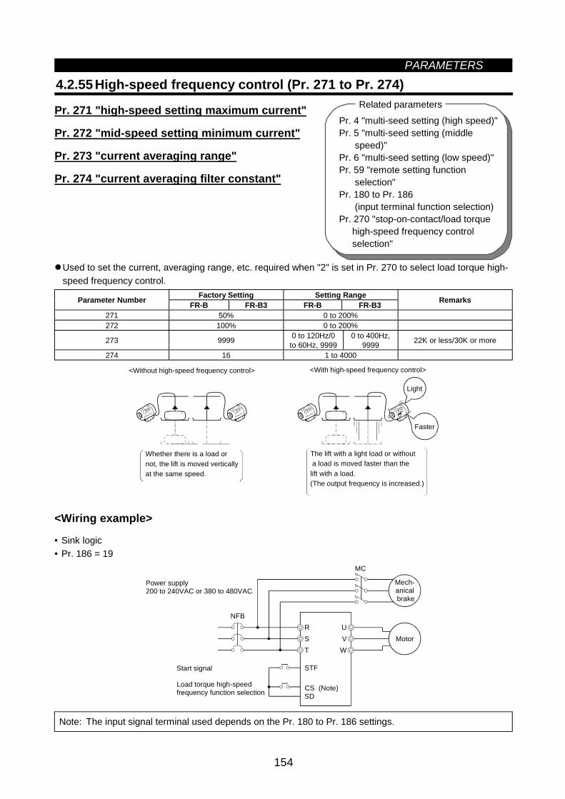
PARAMETERS
154
Pr. 4 "multi-seed setting (high speed)"Pr. 5 "multi-seed setting (middle speed)"Pr. 6 "multi-seed setting (low speed)"Pr. 59 "remote setting function selection"Pr. 180 to Pr. 186 (input terminal function selection)Pr. 270 "stop-on-contact/load torque high-speed frequency control selection"
Related parameters
4.2.55 High-speed frequency control (Pr. 271 to Pr. 274)
Pr. 271 "high-speed setting maximum current"
Pr. 272 "mid-speed setting minimum current"
Pr. 273 "current averaging range"
Pr. 274 "current averaging filter constant"
Used to set the current, averaging range, etc. required when "2" is set in Pr. 270 to select load torque high-speed frequency control.
Factory Setting Setting RangeParameter Number FR-B FR-B3 FR-B FR-B3 Remarks
271 50% 0 to 200%272 100% 0 to 200%
273 9999 0 to 120Hz/0to 60Hz, 9999
0 to 400Hz,9999 22K or less/30K or more
274 16 1 to 4000
The lift with a light load or without a load is moved faster than thelift with a load.(The output frequency is increased.)
<With high-speed frequency control><Without high-speed frequency control>
Whether there is a load ornot, the lift is moved verticallyat the same speed.
Light
Faster
<Wiring example>
• Sink logic• Pr. 186 = 19
R US VT W
MC
STF
SD
NFB
Motor
Power supply200 to 240VAC or 380 to 480VAC
Start signal
Load torque high-speed frequency function selection CS (Note)
Mech-anical brake
Note: The input signal terminal used depends on the Pr. 180 to Pr. 186 settings.
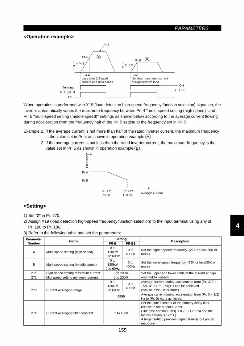
PARAMETERS
155
<Operation example>
CS
STF (STR) OFFON
Pr.5
Pr.4
Pr.5A
× Pr.512 × Pr.51
2
B
Terminal
Less than 1/2 ratedcurrent and driven load
Not less than rated current or regenerative load
When operation is performed with X19 (load detection high-speed frequency function selection) signal on, theinverter automatically varies the maximum frequency between Pr. 4 "multi-speed setting (high speed)" andPr. 5 "multi-speed setting (middle speed)" settings as shown below according to the average current flowingduring acceleration from the frequency half of the Pr. 5 setting to the frequency set in Pr. 5.
Example:1. If the average current is not more than half of the rated inverter current, the maximum frequencyis the value set in Pr. 4 as shown in operation example A .
2. If the average current is not less than the rated inverter current, the maximum frequency is thevalue set in Pr. 5 as shown in operation example B .
Pr.5
Pr.271(50%)
Pr.272(100%) Average current
Freq
uenc
y
Pr.4
<Setting>
1) Set "2" in Pr. 270.2) Assign X19 (load detection high-speed frequency function selection) to the input terminal using any of
Pr. 180 to Pr. 186.3) Refer to the following table and set the parameters:
SettingParameterNumber Name FR-B FR-B3 Description
4 Multi-speed setting (high speed)0 to
120Hz/0 to 60Hz
0 to400Hz
Set the higher-speed frequency. (22K or less/30K ormore)
5 Multi-speed setting (middle speed)0 to
120Hz/0 to 60Hz
0 to400Hz
Set the lower-speed frequency. (22K or less/30K ormore)
271 High-speed setting maximum current 0 to 200%272 Mid-speed setting minimum current 0 to 200%
Set the upper and lower limits of the current at highand middle speeds.
0 to120Hz/
0 to 60Hz
0 to400Hz
Average current during acceleration from (Pr. 273 ×1/2) Hz to (Pr. 273) Hz can be achieved.(22K or less/30K or more)273 Current averaging range
9999 Average current during acceleration from (Pr. 5 × 1/2)Hz to (Pr. 5) Hz is achieved.
274 Current averaging filter constant 1 to 4000
Set the time constant of the primary delay filterrelative to the output current.(The time constant [ms] is 0.75 × Pr. 274 and thefactory setting is 12ms.)A larger setting provides higher stability but poorerresponse.
4
PARAMETERS
156
Note: 1. This function is only valid in the external operation mode. This function is not activated when "1"or "2" (remote setting function) is selected for Pr. 59.
2. If the current averaging zone includes the low output region, the output current may increase inthe constant-output region. When the current is low, the running frequency increases, increasingthe deceleration time.
3. The fast-response current limit function is invalid.4. Can be activated at every start.5. When the terminal functions are changed using Pr. 180 to Pr. 186, the other functions may be
affected. Confirm the functions of the corresponding terminals before making settings.
CAUTION
When the load is light, the motor may accelerate suddenly up to the maximumfrequency, causing hazardous conditions. Provide sufficient interlocks on themachine side before starting operation.
Set frequency reference table for load torque high-speed frequency controlThe following table lists the frequencies set when the load torque high-speed frequency control signal (X19)and multi-speed terminals (RH, RM, RL) are selected together:
Input SignalsX19 RH RM RL Set Frequency
Conforms to load torque high-speed frequency control.Speed 1 (high speed) Pr. 4Speed 2 (middle speed) Pr. 5Speed 3 (low speed) Pr. 6Speed 1 (high speed) Pr. 4Speed 2 (middle speed) Pr. 5Speed 3 (low speed) Pr. 6Speed 6 Pr. 26Speed 5 Pr. 25Speed 4 Pr. 24Speed 6 Pr. 26Speed 4 Pr. 24Speed 7 Pr. 27Speed 5 Pr. 25Speed 7 Pr. 27Setting using terminal 2, 1, 4, JOG
indicates that the signal is on.
Note: 1. Assumes that the external operation command mode is selected and the remote setting functionis not selected.
2. Multi-speeds override the main speeds (across terminals 2-5, 4-5, 1-5).3. When the 12-bit digital speed input (option FR-A5AX) is selected, the above list is invalid.
(The 12-bit digital speed input has the highest priority.)4. Jog operation overrides the above list.
Function list (The following specifications apply to the external operation mode.)
Pr. 270 Setting Load Torque High-SpeedFrequency Control Stop-On-Contact Control Multi-Speeds (7 speeds)
0 × ×1 ×2 ×3
: Indicates that the function is valid.
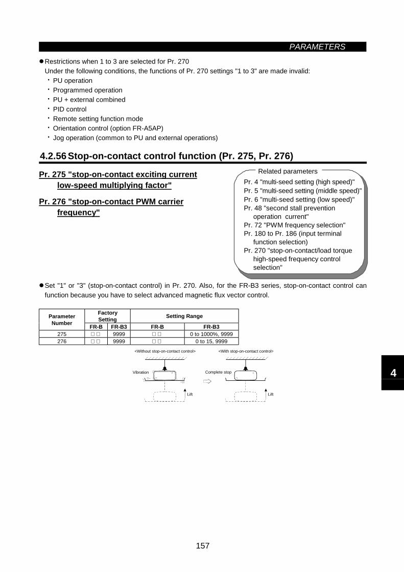
PARAMETERS
157
Pr. 4 "multi-seed setting (high speed)"Pr. 5 "multi-seed setting (middle speed)"Pr. 6 "multi-seed setting (low speed)"Pr. 48 "second stall prevention operation current"Pr. 72 "PWM frequency selection"Pr. 180 to Pr. 186 (input terminal function selection)Pr. 270 "stop-on-contact/load torque high-speed frequency control selection"
Related parameters
Restrictions when 1 to 3 are selected for Pr. 270Under the following conditions, the functions of Pr. 270 settings "1 to 3" are made invalid:· PU operation· Programmed operation· PU + external combined· PID control· Remote setting function mode· Orientation control (option FR-A5AP)· Jog operation (common to PU and external operations)
4.2.56 Stop-on-contact control function (Pr. 275, Pr. 276)
Pr. 275 "stop-on-contact exciting current low-speed multiplying factor"
Pr. 276 "stop-on-contact PWM carrier frequency"
Set "1" or "3" (stop-on-contact control) in Pr. 270. Also, for the FR-B3 series, stop-on-contact control canfunction because you have to select advanced magnetic flux vector control.
FactorySetting Setting RangeParameter
Number FR-B FR-B3 FR-B FR-B3275 9999 0 to 1000%, 9999276 9999 0 to 15, 9999
Lift
<Without stop-on-contact control> <With stop-on-contact control>
Vibration Complete stop
Lift
4
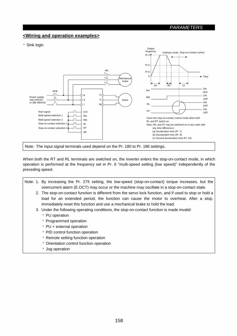
PARAMETERS
158
<Wiring and operation examples>
· Sink logic
NFBR
S
T
STFRHRMRLRT
SD
U
V
W
MC
MotorPower supply200-240VACor 380-480VAC
Stop-on-contact selection 2
Start signalMulti-speed selection 1
Multi-speed selection 2Stop-on-contact selection 1
Mechanicalbrake
(a) (b) (c)
Time
Pr.4
RHONOFF
RMONOFF
RLONOFF
RTONOFF
Pr.5
Pr.6
Output frequency
0
Ordinary mode Stop-on-contact control
Goes into stop-on-contact control mode when both RL and RT switch on.Note: (RL and RT may be switched on in any order with any time difference.) (a) Acceleration time (Pr. 7) (b) Deceleration time (Pr. 8) (c) Second deceleration time (Pr. 44)
Note: The input signal terminals used depend on the Pr. 180 to Pr. 186 settings.
When both the RT and RL terminals are switched on, the inverter enters the stop-on-contact mode, in whichoperation is performed at the frequency set in Pr. 6 "multi-speed setting (low speed)" independently of thepreceding speed.
Note: 1. By increasing the Pr. 275 setting, the low-speed (stop-on-contact) torque increases, but theovercurrent alarm (E.OCT) may occur or the machine may oscillate in a stop-on-contact state.
2. The stop-on-contact function is different from the servo lock function, and if used to stop or hold aload for an extended period, the function can cause the motor to overheat. After a stop,immediately reset this function and use a mechanical brake to hold the load.
3. Under the following operating conditions, the stop-on-contact function is made invalid:· PU operation· Programmed operation· PU + external operation· PID control function operation· Remote setting function operation· Orientation control function operation· Jog operation
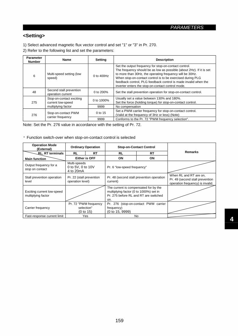
PARAMETERS
159
<Setting>
1) Select advanced magnetic flux vector control and set "1" or "3" in Pr. 270.2) Refer to the following list and set the parameters:
ParameterNumber Name Setting Description
6 Multi-speed setting (lowspeed) 0 to 400Hz
Set the output frequency for stop-on-contact control.The frequency should be as low as possible (about 2Hz). If it is setto more than 30Hz, the operating frequency will be 30Hz.When stop-on-contact control is to be exercised during PLGfeedback control, PLG feedback control is made invalid when theinverter enters the stop-on-contact control mode.
48 Second stall preventionoperation current 0 to 200% Set the stall prevention operation for stop-on-contact control.
0 to 1000% Usually set a value between 130% and 180%.Set the force (holding torque) for stop-on-contact control.275
Stop-on-contact excitingcurrent low-speedmultiplying factor 9999 No compensation
0 to 15 Set a PWM carrier frequency for stop-on-contact control.(Valid at the frequency of 3Hz or less) (Note)276 Stop-on-contact PWM
carrier frequency 9999 Conforms to the Pr. 72 "PWM frequency selection".
Note: Set the Pr. 276 value in accordance with the setting of Pr. 72.
· Function switch-over when stop-on-contact control is selected
Operation Mode(External) Ordinary Operation Stop-on-Contact Control
RL RT RL RTRL, RT terminalsMain function Either is OFF ON ON
Remarks
Output frequency for astop on contact
Multi-speeds0 to 5V, 0 to 10V4 to 20mA
Pr. 6 "low-speed frequency"
Stall prevention operationlevel
Pr. 22 (stall preventionoperation level)
Pr. 48 (second stall prevention operationcurrent)
When RL and RT are on,Pr. 49 (second stall preventionoperation frequency) is invalid.
Exciting current low-speedmultiplying factor
The current is compensated for by themultiplying factor (0 to 1000%) set inPr. 275 before RL and RT are switchedon.
Carrier frequencyPr. 72 "PWM frequency
selection"(0 to 15)
Pr. 276 (stop-on-contact PWM carrierfrequency)(0 to 15, 9999)
Fast-response current limit Yes No 4
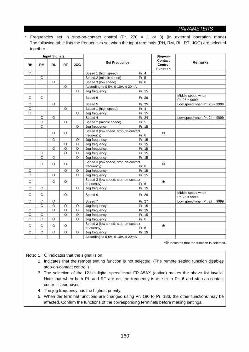
PARAMETERS
160
· Frequencies set in stop-on-contact control (Pr. 270 = 1 or 3) (In external operation mode)The following table lists the frequencies set when the input terminals (RH, RM, RL, RT, JOG) are selectedtogether.
Input Signals
RH RM RL RT JOG Set Frequency
Stop-on-ContactControl
Function
Remarks
Speed 1 (high speed) Pr. 4Speed 2 (middle speed) Pr. 5Speed 3 (low speed) Pr. 6According to 0-5V, 0-10V, 4-20mAJog frequency Pr. 15
Speed 6 Pr. 26 Middle speed whenPr. 26 = 9999
Speed 5 Pr. 25 Low speed when Pr. 25 = 9999Speed 1 (high speed) Pr. 4Jog frequency Pr. 15Speed 4 Pr. 24 Low speed when Pr. 24 = 9999Speed 2 (middle speed) Pr. 5Jog frequency Pr. 15Speed 3 (low speed, stop-on-contactfrequency) Pr. 6Jog frequency Pr. 15Jog frequency Pr. 15Jog frequency Pr. 15Jog frequency Pr. 15Jog frequency Pr. 15Speed 3 (low speed, stop-on-contactfrequency) Pr. 6Jog frequency Pr. 15Jog frequency Pr. 15Speed 3 (low speed, stop-on-contactfrequency) Pr. 6Jog frequency Pr. 15
Speed 6 Pr. 26 Middle speed whenPr. 26 = 9999
Speed 7 Pr. 27 Low speed when Pr. 27 = 9999Jog frequency Pr. 15Jog frequency Pr. 15Jog frequency Pr. 15Jog frequency Pr. 6Speed 3 (low speed, stop-on-contactfrequency) Pr. 6Jog frequency Pr. 15According to 0-5V, 0-10V, 4-20mA
* indicates that the function is selected.
Note: 1. indicates that the signal is on.2. Indicates that the remote setting function is not selected. (The remote setting function disables
stop-on-contact control.)3. The selection of the 12-bit digital speed input FR-A5AX (option) makes the above list invalid.
Note that when both RL and RT are on, the frequency is as set in Pr. 6 and stop-on-contactcontrol is exercised.
4. The jog frequency has the highest priority.5. When the terminal functions are changed using Pr. 180 to Pr. 186, the other functions may be
affected. Confirm the functions of the corresponding terminals before making settings.
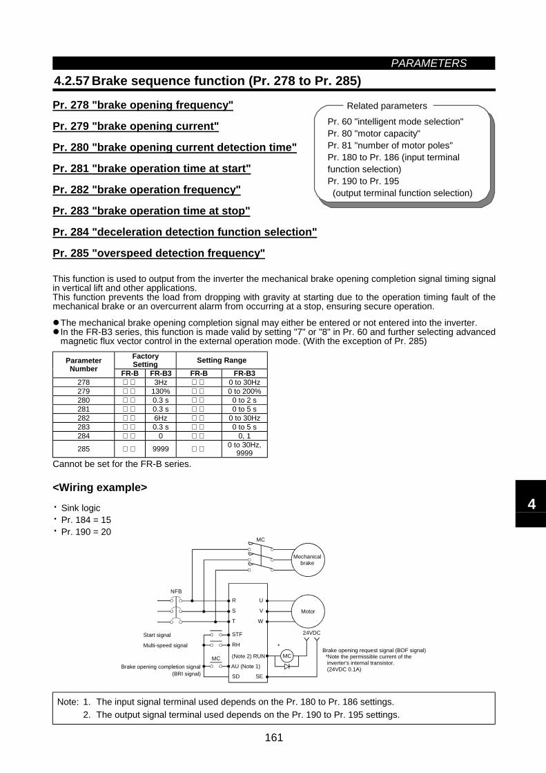
PARAMETERS
161
Pr. 60 "intelligent mode selection"Pr. 80 "motor capacity"Pr. 81 "number of motor poles"Pr. 180 to Pr. 186 (input terminalfunction selection)Pr. 190 to Pr. 195 (output terminal function selection)
Related parameters
4.2.57 Brake sequence function (Pr. 278 to Pr. 285)
Pr. 278 "brake opening frequency"
Pr. 279 "brake opening current"
Pr. 280 "brake opening current detection time"
Pr. 281 "brake operation time at start"
Pr. 282 "brake operation frequency"
Pr. 283 "brake operation time at stop"
Pr. 284 "deceleration detection function selection"
Pr. 285 "overspeed detection frequency"
This function is used to output from the inverter the mechanical brake opening completion signal timing signalin vertical lift and other applications.This function prevents the load from dropping with gravity at starting due to the operation timing fault of themechanical brake or an overcurrent alarm from occurring at a stop, ensuring secure operation.
The mechanical brake opening completion signal may either be entered or not entered into the inverter.In the FR-B3 series, this function is made valid by setting "7" or "8" in Pr. 60 and further selecting advancedmagnetic flux vector control in the external operation mode. (With the exception of Pr. 285)
FactorySetting Setting RangeParameter
Number FR-B FR-B3 FR-B FR-B3278 3Hz 0 to 30Hz279 130% 0 to 200%280 0.3 s 0 to 2 s281 0.3 s 0 to 5 s282 6Hz 0 to 30Hz283 0.3 s 0 to 5 s284 0 0, 1
285 9999 0 to 30Hz,9999
Cannot be set for the FR-B series.
<Wiring example>
· Sink logic· Pr. 184 = 15· Pr. 190 = 20
R U
S V
T W
MC
STF
RH
SD SE
MC MC
24VDC
*
NFB
Brake opening request signal (BOF signal) *Note the permissible current of the inverter's internal transistor. (24VDC 0.1A)
Start signal
Multi-speed signal
Brake opening completion signal
(Note 2) RUN
AU (Note 1)
Mechanical brake
Motor
(BRI signal)
Note: 1. The input signal terminal used depends on the Pr. 180 to Pr. 186 settings.2. The output signal terminal used depends on the Pr. 190 to Pr. 195 settings.
4
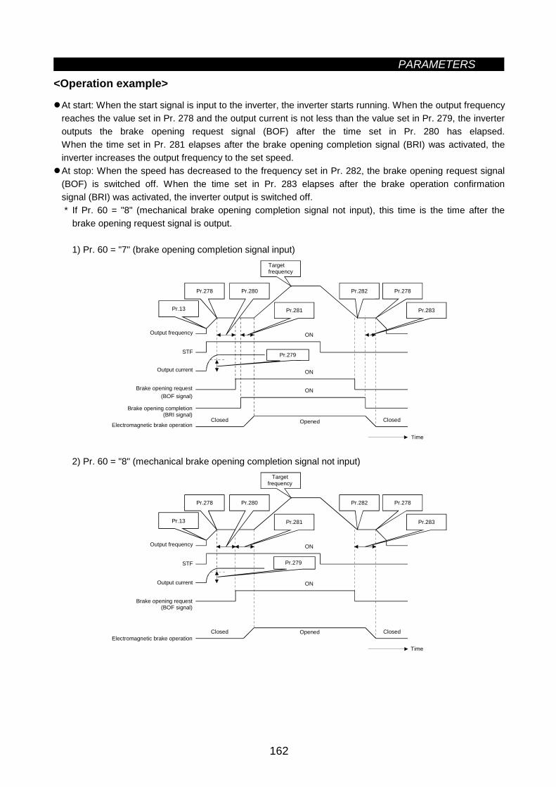
PARAMETERS
162
<Operation example>
At start: When the start signal is input to the inverter, the inverter starts running. When the output frequencyreaches the value set in Pr. 278 and the output current is not less than the value set in Pr. 279, the inverteroutputs the brake opening request signal (BOF) after the time set in Pr. 280 has elapsed.When the time set in Pr. 281 elapses after the brake opening completion signal (BRI) was activated, theinverter increases the output frequency to the set speed.At stop: When the speed has decreased to the frequency set in Pr. 282, the brake opening request signal(BOF) is switched off. When the time set in Pr. 283 elapses after the brake operation confirmationsignal (BRI) was activated, the inverter output is switched off.* If Pr. 60 = "8" (mechanical brake opening completion signal not input), this time is the time after the
brake opening request signal is output.
1) Pr. 60 = "7" (brake opening completion signal input)
STF
ON
ON
Pr.280Pr.278
Pr.13 Pr.281
Pr.278Pr.282
Pr.283
ON
Pr.279
Time
Targetfrequency
Output frequency
Output current
Brake opening request(BOF signal)
Brake opening completion(BRI signal)
Electromagnetic brake operationClosed Opened Closed
2) Pr. 60 = "8" (mechanical brake opening completion signal not input)
STF
ON
ON
Pr.280Pr.278
Pr.13 Pr.281
Pr.278Pr.282
Pr.283
Pr.279
Time
Targetfrequency
Output frequency
Output current
Brake opening request(BOF signal)
Electromagnetic brake operationClosed Opened Closed
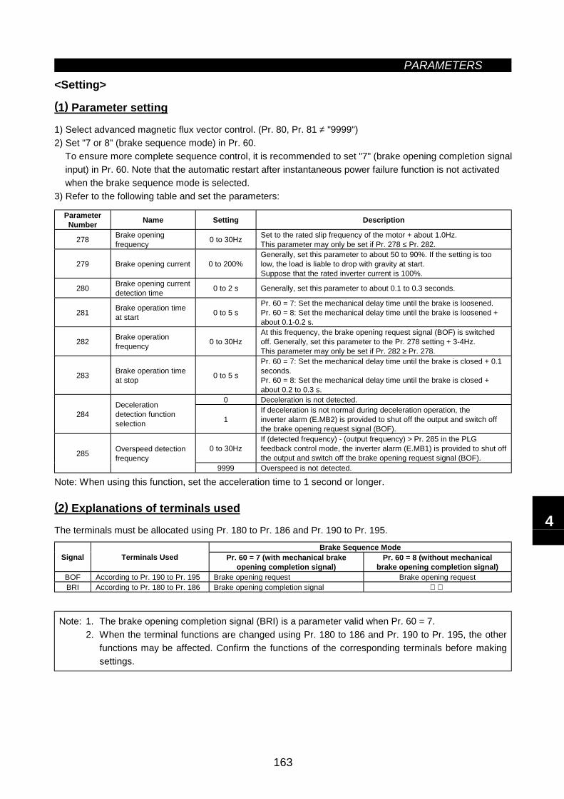
PARAMETERS
163
<Setting>
(1) Parameter setting
1) Select advanced magnetic flux vector control. (Pr. 80, Pr. 81 ≠ "9999")2) Set "7 or 8" (brake sequence mode) in Pr. 60.
To ensure more complete sequence control, it is recommended to set "7" (brake opening completion signalinput) in Pr. 60. Note that the automatic restart after instantaneous power failure function is not activatedwhen the brake sequence mode is selected.
3) Refer to the following table and set the parameters:
ParameterNumber Name Setting Description
278 Brake openingfrequency 0 to 30Hz Set to the rated slip frequency of the motor + about 1.0Hz.
This parameter may only be set if Pr. 278 ≤ Pr. 282.
279 Brake opening current 0 to 200%Generally, set this parameter to about 50 to 90%. If the setting is toolow, the load is liable to drop with gravity at start.Suppose that the rated inverter current is 100%.
280 Brake opening currentdetection time 0 to 2 s Generally, set this parameter to about 0.1 to 0.3 seconds.
281 Brake operation timeat start 0 to 5 s
Pr. 60 = 7: Set the mechanical delay time until the brake is loosened.Pr. 60 = 8: Set the mechanical delay time until the brake is loosened +about 0.1-0.2 s.
282 Brake operationfrequency 0 to 30Hz
At this frequency, the brake opening request signal (BOF) is switchedoff. Generally, set this parameter to the Pr. 278 setting + 3-4Hz.This parameter may only be set if Pr. 282 ≥ Pr. 278.
283 Brake operation timeat stop 0 to 5 s
Pr. 60 = 7: Set the mechanical delay time until the brake is closed + 0.1seconds.Pr. 60 = 8: Set the mechanical delay time until the brake is closed +about 0.2 to 0.3 s.
0 Deceleration is not detected.
284Decelerationdetection functionselection 1
If deceleration is not normal during deceleration operation, theinverter alarm (E.MB2) is provided to shut off the output and switch offthe brake opening request signal (BOF).
0 to 30HzIf (detected frequency) - (output frequency) > Pr. 285 in the PLGfeedback control mode, the inverter alarm (E.MB1) is provided to shut offthe output and switch off the brake opening request signal (BOF).285 Overspeed detection
frequency9999 Overspeed is not detected.
Note: When using this function, set the acceleration time to 1 second or longer.
(2) Explanations of terminals used
The terminals must be allocated using Pr. 180 to Pr. 186 and Pr. 190 to Pr. 195.
Brake Sequence ModeSignal Terminals Used Pr. 60 = 7 (with mechanical brake
opening completion signal)Pr. 60 = 8 (without mechanical
brake opening completion signal)BOF According to Pr. 190 to Pr. 195 Brake opening request Brake opening requestBRI According to Pr. 180 to Pr. 186 Brake opening completion signal
Note: 1. The brake opening completion signal (BRI) is a parameter valid when Pr. 60 = 7.2. When the terminal functions are changed using Pr. 180 to 186 and Pr. 190 to Pr. 195, the other
functions may be affected. Confirm the functions of the corresponding terminals before makingsettings.
4
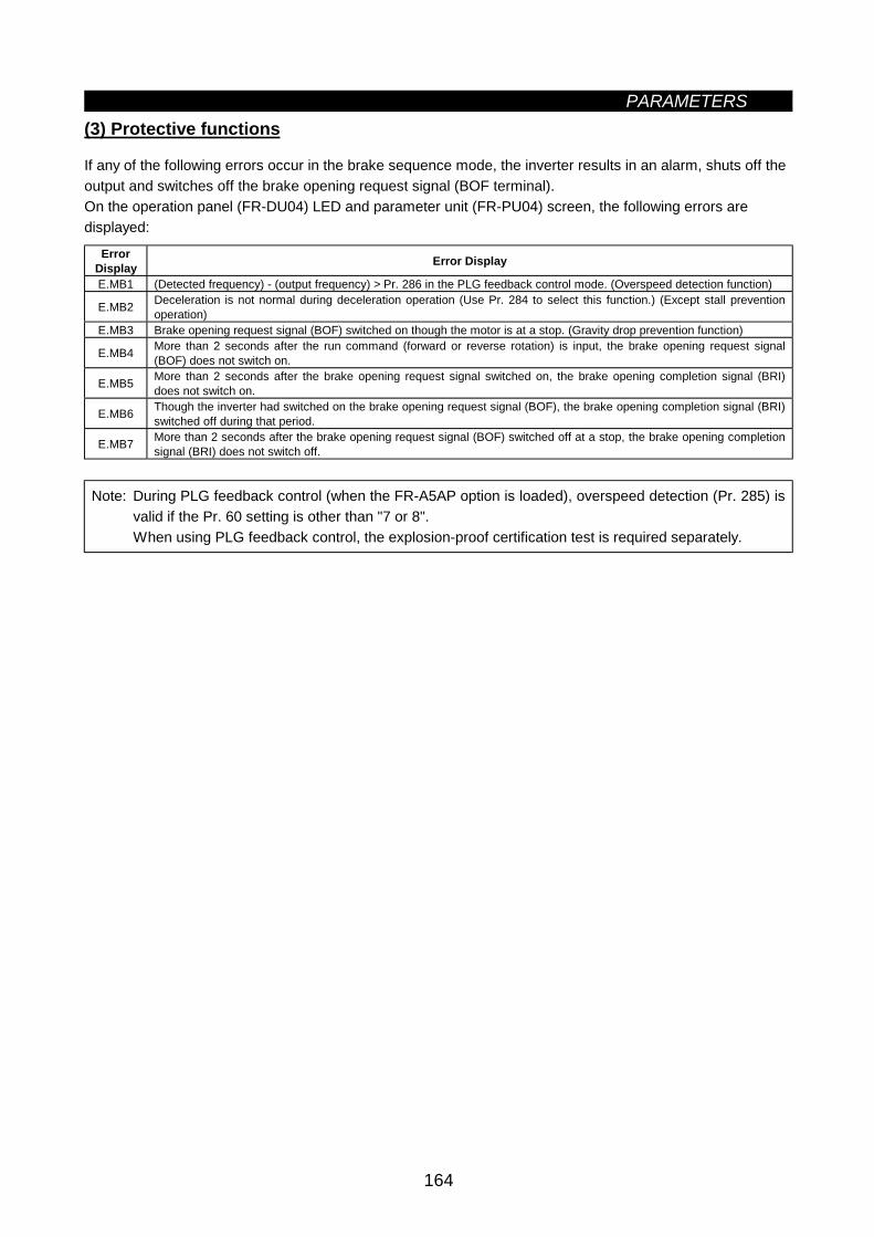
PARAMETERS
164
(3) Protective functions
If any of the following errors occur in the brake sequence mode, the inverter results in an alarm, shuts off theoutput and switches off the brake opening request signal (BOF terminal).On the operation panel (FR-DU04) LED and parameter unit (FR-PU04) screen, the following errors aredisplayed:
ErrorDisplay Error Display
E.MB1 (Detected frequency) - (output frequency) > Pr. 286 in the PLG feedback control mode. (Overspeed detection function)
E.MB2 Deceleration is not normal during deceleration operation (Use Pr. 284 to select this function.) (Except stall preventionoperation)
E.MB3 Brake opening request signal (BOF) switched on though the motor is at a stop. (Gravity drop prevention function)
E.MB4 More than 2 seconds after the run command (forward or reverse rotation) is input, the brake opening request signal(BOF) does not switch on.
E.MB5 More than 2 seconds after the brake opening request signal switched on, the brake opening completion signal (BRI)does not switch on.
E.MB6 Though the inverter had switched on the brake opening request signal (BOF), the brake opening completion signal (BRI)switched off during that period.
E.MB7 More than 2 seconds after the brake opening request signal (BOF) switched off at a stop, the brake opening completionsignal (BRI) does not switch off.
Note: During PLG feedback control (when the FR-A5AP option is loaded), overspeed detection (Pr. 285) isvalid if the Pr. 60 setting is other than "7 or 8".When using PLG feedback control, the explosion-proof certification test is required separately.
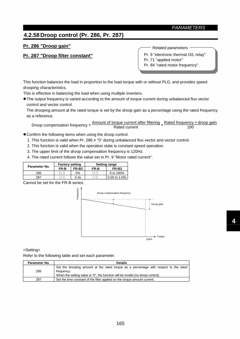
PARAMETERS
165
4.2.58 Droop control (Pr. 286, Pr. 287)
Pr. 286 "Droop gain"
Pr. 287 "Droop filter constant"
This function balances the load in proportion to the load torque with or without PLG, and provides speeddrooping characteristics.This is effective in balancing the load when using multiple inverters.
The output frequency is varied according to the amount of torque current during unbalanced flux vectorcontrol and vector control.The drooping amount at the rated torque is set by the droop gain as a percentage using the rated frequencyas a reference.
Droop compensation frequency = Amount of torque current after filteringRated current ×
Rated frequency × droop gain100
Confirm the following items when using the droop control.1. This function is valid when Pr. 286 ≠ "0" during unbalanced flux vector and vector control.2. This function is valid when the operation state is constant speed operation.3. The upper limit of the droop compensation frequency is 120Hz.4. The rated current follows the value set in Pr. 9 "Motor rated current".
Factory setting Setting rangeParameter No. FR-B FR-B3 FR-B FR-B3286 0% 0 to 100%287 0.3s 0.00 to 1.00s
Cannot be set for the FR-B series.
Droop gain
Torque100%
Droop compensation frequency
Freq
uenc
y
<Setting>Refer to the following table and set each parameter.
Parameter No. Details
286Set the drooping amount at the rated torque as a percentage with respect to the ratedfrequency.When the setting value is "0", the function will be invalid (no droop control).
287 Set the time constant of the filter applied on the torque amount current.
Pr. 9 "electronic thermal O/L relay"Pr. 71 "applied motor"Pr. 84 "rated motor frequency"
Related parameters
4
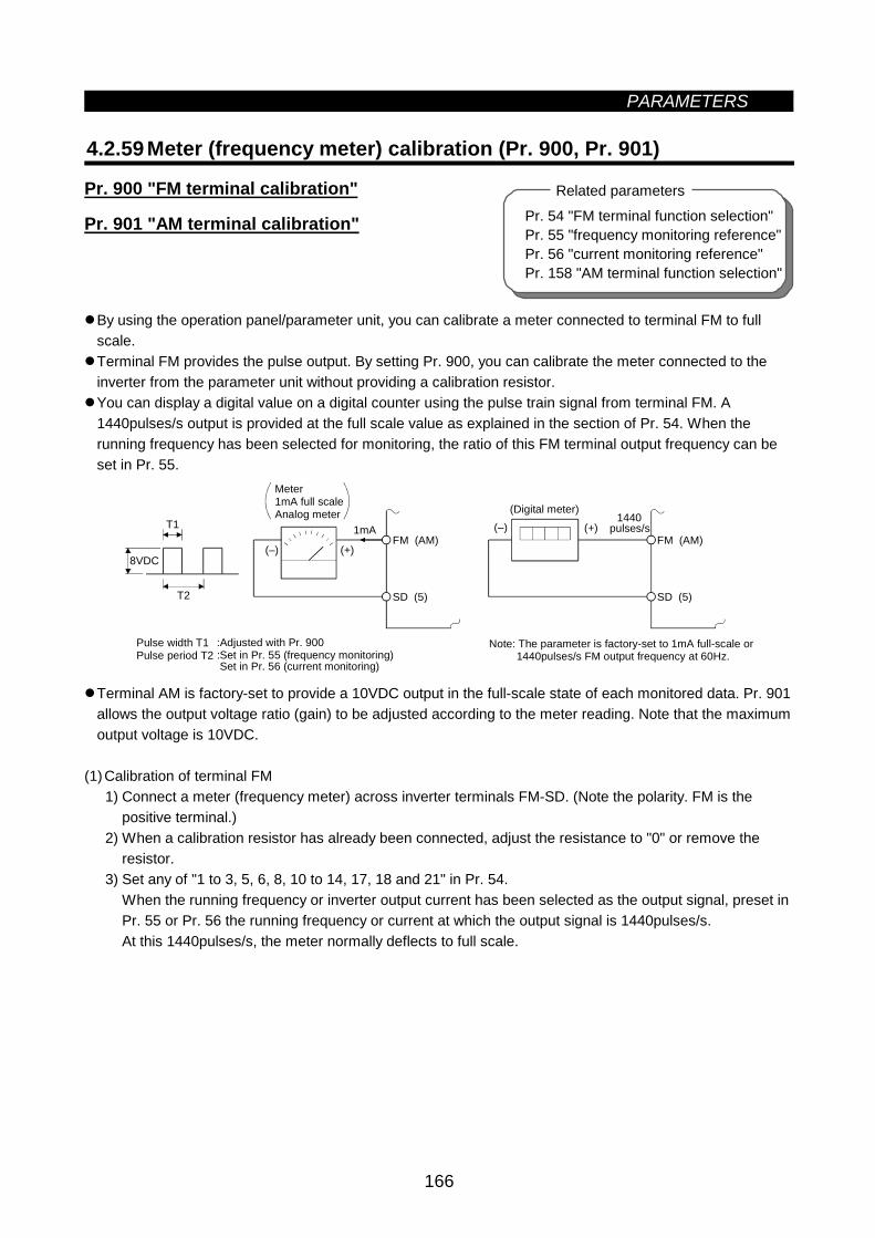
PARAMETERS
166
Pr. 54 "FM terminal function selection"Pr. 55 "frequency monitoring reference"Pr. 56 "current monitoring reference"Pr. 158 "AM terminal function selection"
Related parameters
4.2.59 Meter (frequency meter) calibration (Pr. 900, Pr. 901)
Pr. 900 "FM terminal calibration"
Pr. 901 "AM terminal calibration"
By using the operation panel/parameter unit, you can calibrate a meter connected to terminal FM to fullscale.Terminal FM provides the pulse output. By setting Pr. 900, you can calibrate the meter connected to theinverter from the parameter unit without providing a calibration resistor.You can display a digital value on a digital counter using the pulse train signal from terminal FM. A1440pulses/s output is provided at the full scale value as explained in the section of Pr. 54. When therunning frequency has been selected for monitoring, the ratio of this FM terminal output frequency can beset in Pr. 55.
(–) (+)
1mA
8VDC
T2
T1FM (AM)
SD (5)
(–) (+)FM (AM)
SD (5)
Note: The parameter is factory-set to 1mA full-scale or 1440pulses/s FM output frequency at 60Hz.
Meter1mA full scaleAnalog meter (Digital meter)
Pulse width T1 Pulse period T2
:Adjusted with Pr. 900:Set in Pr. 55 (frequency monitoring)Set in Pr. 56 (current monitoring)
1440pulses/s
Terminal AM is factory-set to provide a 10VDC output in the full-scale state of each monitored data. Pr. 901allows the output voltage ratio (gain) to be adjusted according to the meter reading. Note that the maximumoutput voltage is 10VDC.
(1)Calibration of terminal FM1) Connect a meter (frequency meter) across inverter terminals FM-SD. (Note the polarity. FM is the
positive terminal.)2) When a calibration resistor has already been connected, adjust the resistance to "0" or remove the
resistor.3) Set any of "1 to 3, 5, 6, 8, 10 to 14, 17, 18 and 21" in Pr. 54.
When the running frequency or inverter output current has been selected as the output signal, preset inPr. 55 or Pr. 56 the running frequency or current at which the output signal is 1440pulses/s.At this 1440pulses/s, the meter normally deflects to full scale.
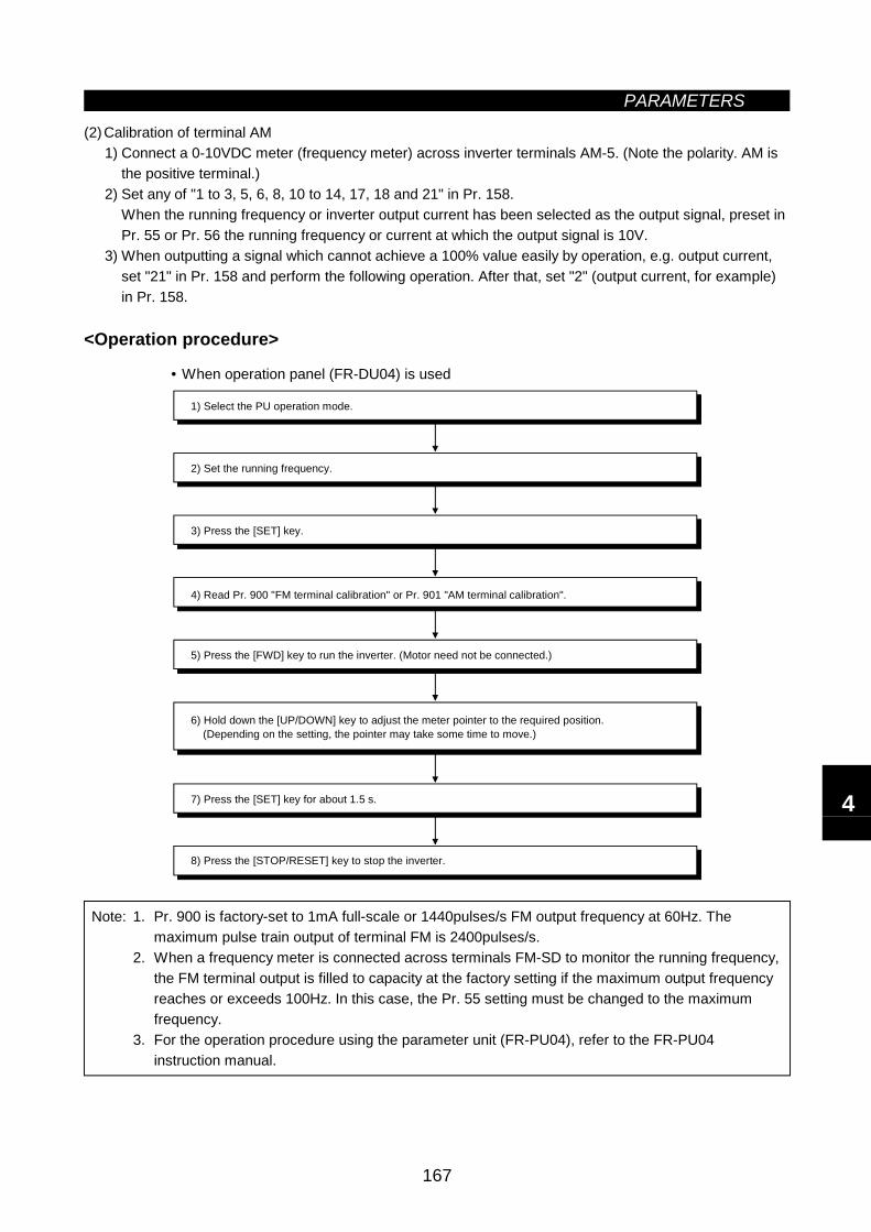
PARAMETERS
167
(2)Calibration of terminal AM1) Connect a 0-10VDC meter (frequency meter) across inverter terminals AM-5. (Note the polarity. AM is
the positive terminal.)2) Set any of "1 to 3, 5, 6, 8, 10 to 14, 17, 18 and 21" in Pr. 158.
When the running frequency or inverter output current has been selected as the output signal, preset inPr. 55 or Pr. 56 the running frequency or current at which the output signal is 10V.
3) When outputting a signal which cannot achieve a 100% value easily by operation, e.g. output current,set "21" in Pr. 158 and perform the following operation. After that, set "2" (output current, for example)in Pr. 158.
<Operation procedure>
• When operation panel (FR-DU04) is used
8) Press the [STOP/RESET] key to stop the inverter.
1) Select the PU operation mode.
2) Set the running frequency.
3) Press the [SET] key.
4) Read Pr. 900 "FM terminal calibration" or Pr. 901 "AM terminal calibration".
5) Press the [FWD] key to run the inverter. (Motor need not be connected.)
7) Press the [SET] key for about 1.5 s.
6) Hold down the [UP/DOWN] key to adjust the meter pointer to the required position. (Depending on the setting, the pointer may take some time to move.)
Note: 1. Pr. 900 is factory-set to 1mA full-scale or 1440pulses/s FM output frequency at 60Hz. Themaximum pulse train output of terminal FM is 2400pulses/s.
2. When a frequency meter is connected across terminals FM-SD to monitor the running frequency,the FM terminal output is filled to capacity at the factory setting if the maximum output frequencyreaches or exceeds 100Hz. In this case, the Pr. 55 setting must be changed to the maximumfrequency.
3. For the operation procedure using the parameter unit (FR-PU04), refer to the FR-PU04instruction manual.
4
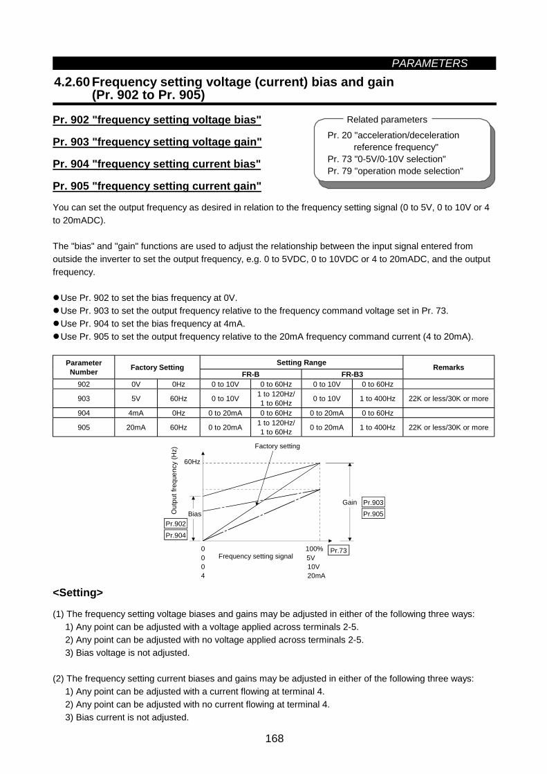
PARAMETERS
168
4.2.60 Frequency setting voltage (current) bias and gain(Pr. 902 to Pr. 905)
Pr. 902 "frequency setting voltage bias"
Pr. 903 "frequency setting voltage gain"
Pr. 904 "frequency setting current bias"
Pr. 905 "frequency setting current gain"
You can set the output frequency as desired in relation to the frequency setting signal (0 to 5V, 0 to 10V or 4to 20mADC).
The "bias" and "gain" functions are used to adjust the relationship between the input signal entered fromoutside the inverter to set the output frequency, e.g. 0 to 5VDC, 0 to 10VDC or 4 to 20mADC, and the outputfrequency.
Use Pr. 902 to set the bias frequency at 0V.Use Pr. 903 to set the output frequency relative to the frequency command voltage set in Pr. 73.Use Pr. 904 to set the bias frequency at 4mA.Use Pr. 905 to set the output frequency relative to the 20mA frequency command current (4 to 20mA).
Setting RangeParameterNumber Factory Setting
FR-B FR-B3Remarks
902 0V 0Hz 0 to 10V 0 to 60Hz 0 to 10V 0 to 60Hz
903 5V 60Hz 0 to 10V 1 to 120Hz/1 to 60Hz 0 to 10V 1 to 400Hz 22K or less/30K or more
904 4mA 0Hz 0 to 20mA 0 to 60Hz 0 to 20mA 0 to 60Hz
905 20mA 60Hz 0 to 20mA 1 to 120Hz/1 to 60Hz 0 to 20mA 1 to 400Hz 22K or less/30K or more
60Hz
Pr.902Pr.904
Pr.903
Pr.73
Pr.905Gain
Out
put f
requ
ency
(Hz)
Bias
Factory setting
Frequency setting signal004
05V10V20mA
100%
<Setting>
(1) The frequency setting voltage biases and gains may be adjusted in either of the following three ways:1) Any point can be adjusted with a voltage applied across terminals 2-5.2) Any point can be adjusted with no voltage applied across terminals 2-5.3) Bias voltage is not adjusted.
(2) The frequency setting current biases and gains may be adjusted in either of the following three ways:1) Any point can be adjusted with a current flowing at terminal 4.2) Any point can be adjusted with no current flowing at terminal 4.3) Bias current is not adjusted.
Pr. 20 "acceleration/decelerationreference frequency"
Pr. 73 "0-5V/0-10V selection"Pr. 79 "operation mode selection"
Related parameters
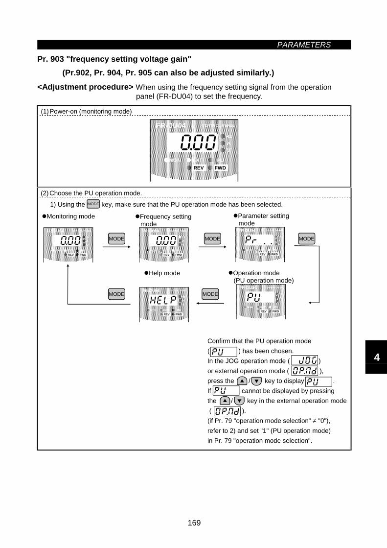
PARAMETERS
169
Pr. 903 "frequency setting voltage gain"(Pr.902, Pr. 904, Pr. 905 can also be adjusted similarly.)
<Adjustment procedure> When using the frequency setting signal from the operationpanel (FR-DU04) to set the frequency.
(1)Power-on (monitoring mode)
FR-DU04 CONTROL PANEL
Hz
MON EXT PU
AV
REV FWD
(2)Choose the PU operation mode.
1) Using the MODE key, make sure that the PU operation mode has been selected.
Monitoring mode
MODE
Frequency setting mode
Parameter setting mode
Help mode Operation mode (PU operation mode)
MODE MODE
MODE MODE
Confirm that the PU operation mode ( ) has been chosen.In the JOG operation mode ( ) or external operation mode ( ), press the / key to display .If cannot be displayed by pressing the / key in the external operation mode ( ).(if Pr. 79 "operation mode selection" ≠ "0"), refer to 2) and set "1" (PU operation mode) in Pr. 79 "operation mode selection".
FR-DU04 CONTROL PANEL
Hz
MON EXT PU
AV
REV FWD
FR-DU04 CONTROL PANEL
Hz
MON EXT PU
AV
REV FWD
FR-DU04 CONTROL PANEL
Hz
MON EXT PU
AV
REV FWD
FR-DU04 CONTROL PANEL
Hz
MON EXT PU
AV
REV FWD
FR-DU04 CONTROL PANEL
Hz
MON EXT PU
AV
REV FWD
4
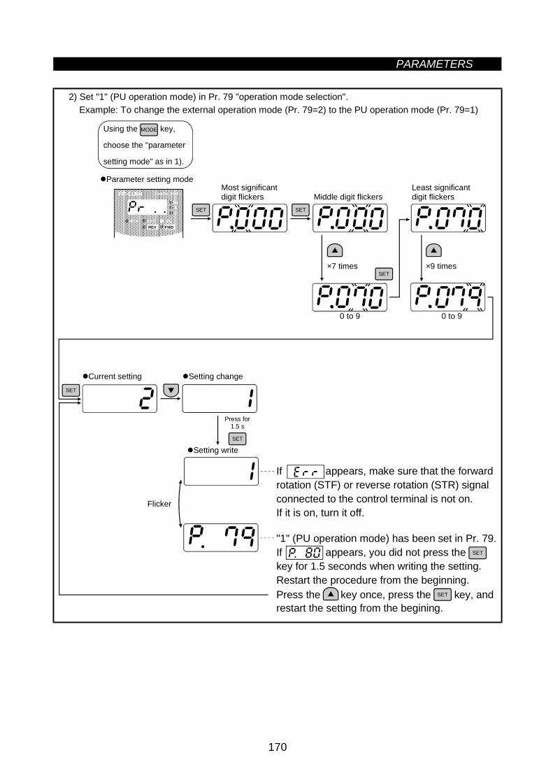
PARAMETERS
170
2) Set "1" (PU operation mode) in Pr. 79 "operation mode selection".Example: To change the external operation mode (Pr. 79=2) to the PU operation mode (Pr. 79=1)
SET
SET
Current setting Setting change
Press for1.5 s
SET
Middle digit flickersMost significantdigit flickers
SET
Least significantdigit flickers
0 to 9
SET
Parameter setting mode
Using the key,
choose the "parameter
setting mode" as in 1).
MODE
×7 times ×9 times
Setting write
Flicker
0 to 9
If appears, make sure that the forwardrotation (STF) or reverse rotation (STR) signalconnected to the control terminal is not on.If it is on, turn it off.
SET
"1" (PU operation mode) has been set in Pr. 79.If appears, you did not press the key for 1.5 seconds when writing the setting.Restart the procedure from the beginning.
FR-DU04 CONTROL PANEL
Hz
MON EXT PU
AV
REV FWD
Press the key once, press the key, andrestart the setting from the begining.
SET
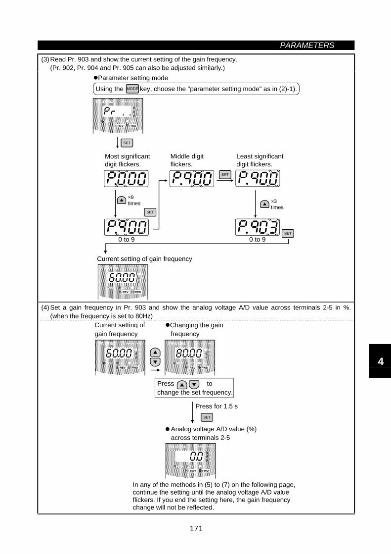
PARAMETERS
171
(3)Read Pr. 903 and show the current setting of the gain frequency.(Pr. 902, Pr. 904 and Pr. 905 can also be adjusted similarly.)
SET
0 to 9 0 to 9
Most significantdigit flickers.
Middle digitflickers.
Least significantdigit flickers.
Current setting of gain frequency
SET
SET
SET
Parameter setting modeUsing the key, choose the "parameter setting mode" as in (2)-1).MODE
×9times ×3
times
FR-DU04 CONTROL PANEL
Hz
MON EXT PU
AV
REV FWD
FR-DU04 CONTROL PANEL
Hz
MON EXT PU
AV
REV FWD
(4)Set a gain frequency in Pr. 903 and show the analog voltage A/D value across terminals 2-5 in %.(when the frequency is set to 80Hz)
Press for 1.5 s
Current setting ofgain frequency
Changing the gain frequency
Press tochange the set frequency.
SET
In any of the methods in (5) to (7) on the following page, continue the setting until the analog voltage A/D value flickers. If you end the setting here, the gain frequency change will not be reflected.
FR-DU04 CONTROL PANEL
Hz
MON EXT PU
AV
REV FWD
FR-DU04 CONTROL PANEL
Hz
MON EXT PU
AV
REV FWD
FR-DU04 CONTROL PANEL
Hz
MON EXT PU
AV
REV FWD
Analog voltage A/D value (%) across terminals 2-5
4
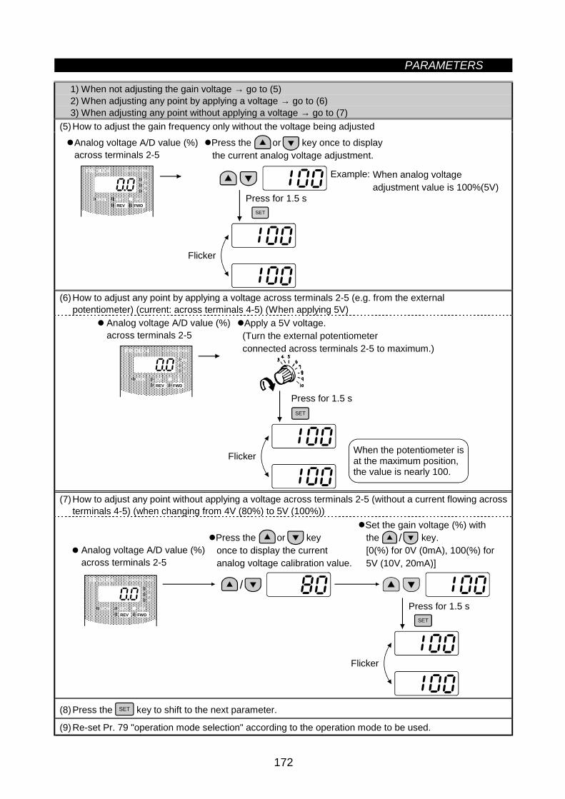
PARAMETERS
172
1) When not adjusting the gain voltage → go to (5)2) When adjusting any point by applying a voltage → go to (6)3) When adjusting any point without applying a voltage → go to (7)
(5)How to adjust the gain frequency only without the voltage being adjusted
Press for 1.5 sSET
Flicker
Press the or key once to display the current analog voltage adjustment.
Example: When analog voltageadjustment value is 100%(5V)
FR-DU04 CONTROL PANEL
Hz
MON EXT PU
AV
REV FWD
Analog voltage A/D value (%)across terminals 2-5
(6)How to adjust any point by applying a voltage across terminals 2-5 (e.g. from the externalpotentiometer) (current: across terminals 4-5) (When applying 5V)
Press for 1.5 s
Flicker
Apply a 5V voltage. (Turn the external potentiometer connected across terminals 2-5 to maximum.)
SET
When the potentiometer isat the maximum position, the value is nearly 100.
FR-DU04 CONTROL PANEL
Hz
MON EXT PU
AV
REV FWD
Analog voltage A/D value (%)across terminals 2-5
(7)How to adjust any point without applying a voltage across terminals 2-5 (without a current flowing acrossterminals 4-5) (when changing from 4V (80%) to 5V (100%))
Press for 1.5 s
Flicker
SET
Press the or key once to display the current analog voltage calibration value.
Set the gain voltage (%) with the key. [0(%) for 0V (0mA), 100(%) for 5V (10V, 20mA)]
/
/
FR-DU04 CONTROL PANEL
Hz
MON EXT PU
AV
REV FWD
Analog voltage A/D value (%)across terminals 2-5
(8)Press the SET key to shift to the next parameter.
(9)Re-set Pr. 79 "operation mode selection" according to the operation mode to be used.
PARAMETERS
173
Note: 1. If the Pr. 903 or Pr. 905 (gain adjustment) value is changed, the Pr. 20 value does not change.The input signal to terminal 1 (frequency setting auxiliary input) is added to the frequency settingsignal.
2. For the operation procedure using the parameter unit (FR-PU04), refer to the FR-PU04 instructionmanual.
CAUTION
Be careful when setting any value other than "0" as the bias frequency at 0V. Even withoutthe speed command, the motor will start running at the set frequency by merelyswitching on the start signal.
4.2.61 Buzzer control (Pr. 990)
Pr. 990 "buzzer control"
You can make the buzzer "beep" when you press any key of the operation panel or parameter unit.
Factory Setting Setting RangeParameterNumber FR-B FR-B3 FR-B FR-B3
Remarks
990 1 0, 1 0: Without beep, 1: With beep
4

MEMO
5
CHAPTER 5PROTECTIVE FUNCTIONS
This chapter explains the "protective functions" of thisproduct.Always read the instructions before using the equipment.
5.1 Errors (Alarms) ........................................................174 5.2 Troubleshooting .......................................................184 5.3 Precautions for Maintenance and Inspection ...........186
Chapter 1
Chapter 2
Chapter 3
Chapter 4
Chapter 5
Chapter 6
Chapter 7
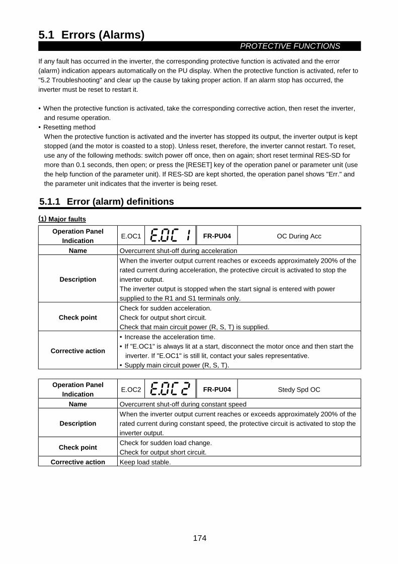
5.1 Errors (Alarms)PROTECTIVE FUNCTIONS
174
5 PROTECTIVE FUNCTIONS5.1 Errors (Alarms)
If any fault has occurred in the inverter, the corresponding protective function is activated and the error(alarm) indication appears automatically on the PU display. When the protective function is activated, refer to"5.2 Troubleshooting" and clear up the cause by taking proper action. If an alarm stop has occurred, theinverter must be reset to restart it.
• When the protective function is activated, take the corresponding corrective action, then reset the inverter,and resume operation.
• Resetting methodWhen the protective function is activated and the inverter has stopped its output, the inverter output is keptstopped (and the motor is coasted to a stop). Unless reset, therefore, the inverter cannot restart. To reset,use any of the following methods: switch power off once, then on again; short reset terminal RES-SD formore than 0.1 seconds, then open; or press the [RESET] key of the operation panel or parameter unit (usethe help function of the parameter unit). If RES-SD are kept shorted, the operation panel shows "Err." andthe parameter unit indicates that the inverter is being reset.
5.1.1 Error (alarm) definitions(1) Major faults
Operation PanelIndication E.OC1 FR-PU04 OC During Acc
Name Overcurrent shut-off during acceleration
Description
When the inverter output current reaches or exceeds approximately 200% of therated current during acceleration, the protective circuit is activated to stop theinverter output.The inverter output is stopped when the start signal is entered with powersupplied to the R1 and S1 terminals only.
Check pointCheck for sudden acceleration.Check for output short circuit.Check that main circuit power (R, S, T) is supplied.
Corrective action
• Increase the acceleration time.• If "E.OC1" is always lit at a start, disconnect the motor once and then start the
inverter. If "E.OC1" is still lit, contact your sales representative.• Supply main circuit power (R, S, T).
Operation PanelIndication E.OC2 FR-PU04 Stedy Spd OC
Name Overcurrent shut-off during constant speed
DescriptionWhen the inverter output current reaches or exceeds approximately 200% of therated current during constant speed, the protective circuit is activated to stop theinverter output.
Check point Check for sudden load change.Check for output short circuit.
Corrective action Keep load stable.
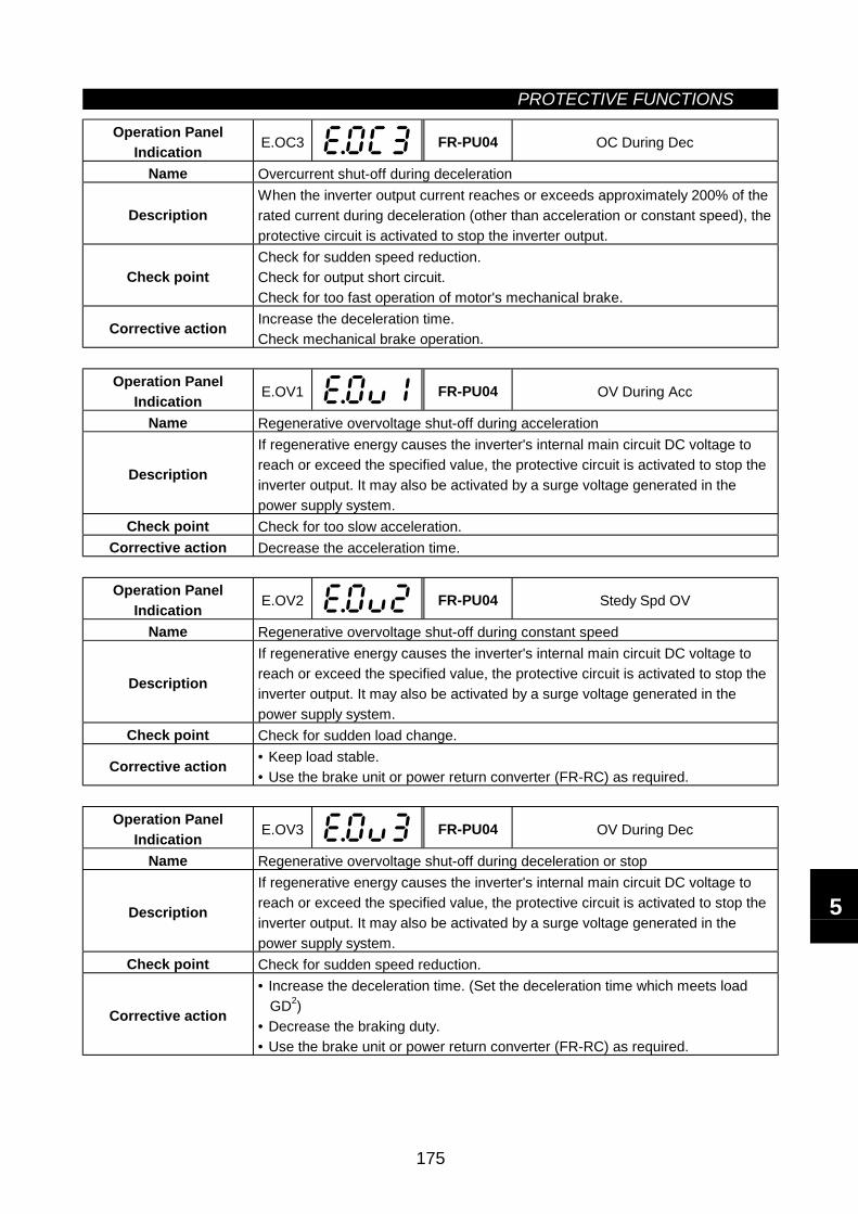
PROTECTIVE FUNCTIONS
175
Operation PanelIndication E.OC3 FR-PU04 OC During Dec
Name Overcurrent shut-off during deceleration
DescriptionWhen the inverter output current reaches or exceeds approximately 200% of therated current during deceleration (other than acceleration or constant speed), theprotective circuit is activated to stop the inverter output.
Check pointCheck for sudden speed reduction.Check for output short circuit.Check for too fast operation of motor's mechanical brake.
Corrective action Increase the deceleration time.Check mechanical brake operation.
Operation PanelIndication E.OV1 FR-PU04 OV During Acc
Name Regenerative overvoltage shut-off during acceleration
Description
If regenerative energy causes the inverter's internal main circuit DC voltage toreach or exceed the specified value, the protective circuit is activated to stop theinverter output. It may also be activated by a surge voltage generated in thepower supply system.
Check point Check for too slow acceleration.Corrective action Decrease the acceleration time.
Operation PanelIndication E.OV2 FR-PU04 Stedy Spd OV
Name Regenerative overvoltage shut-off during constant speed
Description
If regenerative energy causes the inverter's internal main circuit DC voltage toreach or exceed the specified value, the protective circuit is activated to stop theinverter output. It may also be activated by a surge voltage generated in thepower supply system.
Check point Check for sudden load change.
Corrective action • Keep load stable.• Use the brake unit or power return converter (FR-RC) as required.
Operation PanelIndication E.OV3 FR-PU04 OV During Dec
Name Regenerative overvoltage shut-off during deceleration or stop
Description
If regenerative energy causes the inverter's internal main circuit DC voltage toreach or exceed the specified value, the protective circuit is activated to stop theinverter output. It may also be activated by a surge voltage generated in thepower supply system.
Check point Check for sudden speed reduction.
Corrective action
• Increase the deceleration time. (Set the deceleration time which meets load GD2)• Decrease the braking duty.• Use the brake unit or power return converter (FR-RC) as required.
5
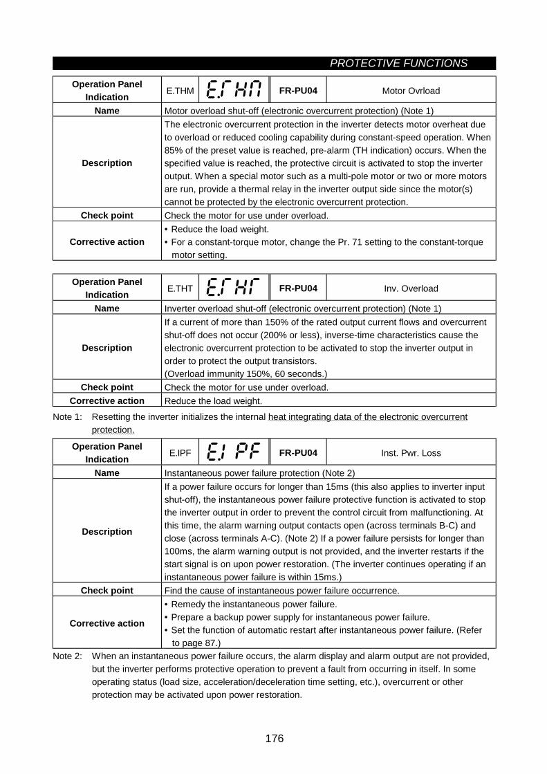
PROTECTIVE FUNCTIONS
176
Operation PanelIndication E.THM FR-PU04 Motor Ovrload
Name Motor overload shut-off (electronic overcurrent protection) (Note 1)
Description
The electronic overcurrent protection in the inverter detects motor overheat dueto overload or reduced cooling capability during constant-speed operation. When85% of the preset value is reached, pre-alarm (TH indication) occurs. When thespecified value is reached, the protective circuit is activated to stop the inverteroutput. When a special motor such as a multi-pole motor or two or more motorsare run, provide a thermal relay in the inverter output side since the motor(s)cannot be protected by the electronic overcurrent protection.
Check point Check the motor for use under overload.
Corrective action• Reduce the load weight.• For a constant-torque motor, change the Pr. 71 setting to the constant-torque
motor setting.
Operation PanelIndication E.THT FR-PU04 Inv. Overload
Name Inverter overload shut-off (electronic overcurrent protection) (Note 1)
Description
If a current of more than 150% of the rated output current flows and overcurrentshut-off does not occur (200% or less), inverse-time characteristics cause theelectronic overcurrent protection to be activated to stop the inverter output inorder to protect the output transistors.(Overload immunity 150%, 60 seconds.)
Check point Check the motor for use under overload.Corrective action Reduce the load weight.
Note 1: Resetting the inverter initializes the internal heat integrating data of the electronic overcurrentprotection.
Operation PanelIndication E.IPF FR-PU04 Inst. Pwr. Loss
Name Instantaneous power failure protection (Note 2)
Description
If a power failure occurs for longer than 15ms (this also applies to inverter inputshut-off), the instantaneous power failure protective function is activated to stopthe inverter output in order to prevent the control circuit from malfunctioning. Atthis time, the alarm warning output contacts open (across terminals B-C) andclose (across terminals A-C). (Note 2) If a power failure persists for longer than100ms, the alarm warning output is not provided, and the inverter restarts if thestart signal is on upon power restoration. (The inverter continues operating if aninstantaneous power failure is within 15ms.)
Check point Find the cause of instantaneous power failure occurrence.
Corrective action
• Remedy the instantaneous power failure.• Prepare a backup power supply for instantaneous power failure.• Set the function of automatic restart after instantaneous power failure. (Refer to page 87.)
Note 2: When an instantaneous power failure occurs, the alarm display and alarm output are not provided,but the inverter performs protective operation to prevent a fault from occurring in itself. In someoperating status (load size, acceleration/deceleration time setting, etc.), overcurrent or otherprotection may be activated upon power restoration.

PROTECTIVE FUNCTIONS
177
Operation PanelIndication E.UVT FR-PU04 Under Voltage
Name Undervoltage protection
Description
If the power supply voltage of the inverter reduces, the control circuit will notoperate properly and will result in decreased motor torque or increased heatgeneration. To prevent this, if the power supply voltage reduces below 150V(about 300V for the 400V class), this function stops the inverter output.When a jumper is not connected across P-P1, the undervoltage protectivefunction is activated.
Check point Check for start of large-capacity motor.Check that a jumper or DC reactor is connected across terminals P-P1.
Corrective action Check the power supply system equipment such as power supply.Connect a jumper or DC reactor across terminals P-P1.
Operation PanelIndication E.FIN FR-PU04 H/Sink O/Temp
Name Fin overheat
Description If the cooling fin overheats, the overheat sensor is actuated to stop the inverteroutput.
Check point • Check for too high ambient temperature.• Check for cooling fin clogging.
Corrective action Set the ambient temperature to within the specifications.
Operation PanelIndication E.GF FR-PU04 Ground Fault
Name Output side ground fault overcurrent protection
Description This function stops the inverter output if a ground fault overcurrent flows due to aground fault which occurred in the inverter's output side (load side).
Check point Check for a ground fault in the motor and connection cable.Corrective action Remedy the ground fault portion.
Operation PanelIndication E.OHT FR-PU04 OH Fault
Name External thermal relay operation (Note 3)
Description
If the external thermal relay designed for motor overheat protection or theinternally mounted temperature relay in the motor switches on (contacts open),the inverter output is stopped. If the relay contacts are reset automatically, theinverter will not restart unless it is reset.
Check point• Check for motor overheating.• Check that the value of 7 (OH signal) is set correctly in any of Pr. 180 to Pr. 186 (input terminal function selection).
Corrective action Reduce the load and operating duty.
Note 3: The output terminals used must be allocated using Pr. 190 to Pr. 195 (output terminal functionselection). This function is activated only when OH has been set to any of Pr. 180 to Pr. 186 (inputterminal function selection).
5
PROTECTIVE FUNCTIONS
178
Operation PanelIndication E.BE FR-PU04 Br. Cct. Fault
Name Brake transistor alarm detection
DescriptionIf the brake circuit fault has occurred due to damaged brake transistors, etc., thisfunction stops the inverter output.In this case, the inverter power must be switched off immediately.
Check point• Reduce load GD2.• Check that the frequency of using the brake is proper.
Corrective action Change the inverter.
Operation PanelIndication E.OLT FR-PU04 Still Prev STP ( OL shown during stall
prevention operation)Name Stall prevention
Description The running frequency has fallen to 0 by stall prevention activated. (OL while stallprevention is being activated.)
Check point Check the motor for use under overload.Corrective action Reduce the load weight.
Operation PanelIndication E.OPT FR-PU04 Option Fault
Name Option alarm
Description
Stops the inverter output if the dedicated option used in the inverter results insetting error or connection (connector) fault.Appears by connecting an AC power supply to R, S, T when you have set highpower factor converter connection.
Check point Check that the plugged-in option connector is plugged securely.
Corrective action • Connect the plugged-in option securely.• Contact your sales representative.
Operation PanelIndication
E.OP1 toOP3
FR-PU04 Option slot alarm 1 to 3
Name Option slot alarm
DescriptionStops the inverter output if a functional alarm occurs in the plug-in option loadedin the corresponding slot (e.g. communication alarm of the communicationoption).
Check point Check for a wrong option function setting and operation.(1 to 3 indicates the option slot numbers.)
Corrective action Confirm the option function setting, etc.
Operation PanelIndication E.PE FR-PU04 Corrupt Memry
Name Parameter storage device alarm
DescriptionStops the inverter output if a fault occurs in the E2PROM device which storesparameter settings.
Check point Check for too many number of parameter write times.Corrective action Contact your sales representative.
PROTECTIVE FUNCTIONS
179
Operation PanelIndication E.PUE FR-PU04 PU Leave Out
Name Parameter unit disconnection
Description
This function stops the inverter output if communication between the inverter and PUis suspended, e.g. the operation panel or PU is disconnected, when "2", "3", "16" or"17" was set in Pr. 75 "reset selection/disconnected PU detection/PU stop selection".This function stops the inverter output if the number of successive communicationerrors is greater than the permissible number of retries when the Pr. 121 value is"9999" for RS-485 communication from the PU connector. This function stops theinverter output if communication is broken for the time set in Pr. 122.
Check point • Check for loose fitting of the DU or PU.• Check the Pr. 75 setting.
Corrective action Fit the DU and PU securely.
Operation PanelIndication E.RET FR-PU04 Retry No Over
Name Retry count exceeded
Description If operation cannot be resumed properly within the number of retries set, thisfunction stops the inverter output.
Check point Find the cause of alarm occurrence.Corrective action Eliminate the cause of the error preceding this error indication.
Operation PanelIndication E.LF FR-PU04
Name Output phase failure protection
Description• This function stops the inverter output if one of the three phases (U, V, W) on
the inverter′s output side (load side) results in open phase.• Check if the rated motor current is extremely lower than the rated inverter current.
Check point Check the wiring (Check the motor for a fault).
Corrective action • Check the cables properly.• Check the setting of Pr. 251 "output phase failure protection selection".
Operation PanelIndication E.CPU FR-PU04 CPU Fault
Name CPU error
Description If the arithmetic operation of the built-in CPU does not end within a predeterminedperiod, the inverter self-determines it as an alarm and stops the output.
Check point
Corrective action • Make connection securely.• Contact your sales representative.
E. 6 Fault 6Operation PanelIndication E. 7
FR-PU04Fault 7
Name CPU error
DescriptionIf the arithmetic operation of the peripheral circuit of the built-in CPU does notend within a predetermined period or if there is an error in the receive data of thebuilt-in CPU, the inverter self-determines it as an alarm and stops the output.
Check point Check for a loose connector.
Corrective action • Make connection securely.• Contact your sales representative.
5
PROTECTIVE FUNCTIONS
180
Operation PanelIndication E.P24 FR-PU04
Name 24VDC power output short circuit
Description
When the 24VDC power output from the PC terminal is shorted, this functionshuts off the power output. At this time, all external contact inputs switch off. Theinverter cannot be reset by entering the RES signal. To reset, use the operationpanel or switch power off, then on again.
Check point Check for a short circuit in the PC terminal output.Corrective action Remedy the short circuit portion.
Operation PanelIndication E.CTE FR-PU04
Name Operation panel power supply short circuit
Description
When the operation panel power supply (P5S of the PU connector) is shorted,this function shuts off the power supply output. At this time, the operation panel(parameter unit) cannot be used and RS-485 communication from the PUconnector cannot be made. To reset, enter the RES signal or switch power off,then on again.
Check point Check for a short circuit in the PU connector cable.Corrective action Check the PU and cable.
Operation PanelIndication
E.MB1to 7
FR-PU04
Name Brake sequence error (Note 5)
Description The inverter output is stopped when a sequence error occurs during use of thebrake sequence function (Pr. 278 to Pr. 285).
Check point Find the cause of alarm occurrence.Corrective action Perform parameter setting check and wiring properly.
Note 5: No indication for the FR-B series.
(2) Minor fault
Operation PanelIndication FN FR-PU04 Fan fault
Name Fan fault
DescriptionFor the inverter, which contains a cooling fan, FN appears on the operation panelwhen the cooling fan stops due to a fault or operates differently from the settingof Pr. 244 "cooling fan operation selection".
Check point Check the cooling fan for a fault.Corrective action Change the fan.
PROTECTIVE FUNCTIONS
181
(3) Warnings
Operation PanelIndication OL FR-PU04 OL (Stall Prev STP)
Name Stall prevention (Over current)
Duringacceleration
If a current of more than 150% (Note 4) of the rated invertercurrent flows in the motor, this function stops the increase infrequency until the overload current reduces to prevent theinverter from resulting in overcurrent shut-off. When theoverload current has reduced below 150%, this functionincreases the frequency again.
Description
During constant-speed operation
If a current of more than 150% (Note 4) of the rated invertercurrent flows in the motor, this function lowers the frequencyuntil the overload current reduces to prevent overcurrentshut-off. When the overload current has reduced below150%, this function increases the frequency up to the setvalue.
Duringdeceleration
If a current of more than 150% (Note 4) of the rated invertercurrent flows in the motor, this function stops the decrease infrequency until the overload current reduces to prevent theinverter from resulting in overcurrent shut-off. When theoverload current has reduced below 150%, this functiondecreases the frequency again.
Check point Check the motor for use under overload.
Corrective actionThe acceleration time may change. Increase the stall prevention operation levelusing Pr. 22 "stall prevention operation level" or make the stall preventioninoperative using Pr. 156 "stall prevention operation selection".
Note 4: The stall prevention operation current may be set as desired. It is factory-set to 150%.
Operation PanelIndication oL FR-PU04 oL
Name Stall prevention (overvoltage)
Description Duringdeceleration
If the regenerative energy of the motor increases too much toexceed the brake capability, this function stops the decreasein frequency to prevent overvoltage shut-off. As soon as theregenerative energy has reduced, deceleration resumes.
Check point Check for sudden speed reduction.
Corrective action The deceleration time may change. Increase the deceleration time using Pr. 8"deceleration time".
Operation PanelIndication PS FR-PU04 PS
Name PU stop
Description A stop made by pressing the [STOP] key of the PU has been set in Pr. 75 "PUstop selection".
Check point Check for a stop made by pressing the STOP key of the operation panel.Corrective action Refer to page 98.
5
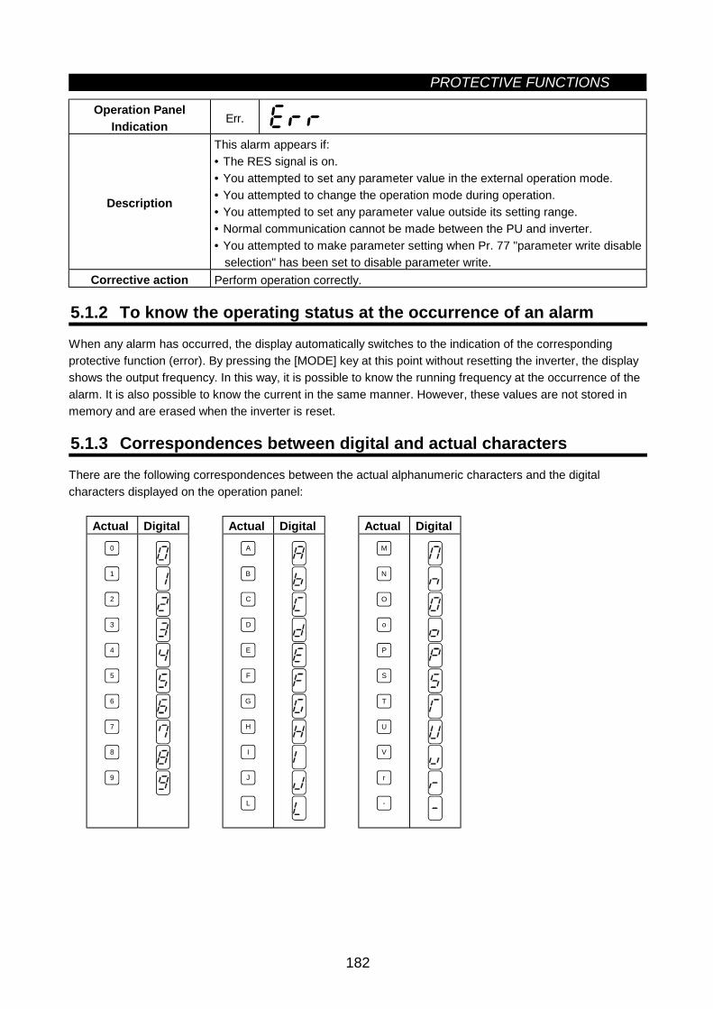
PROTECTIVE FUNCTIONS
182
Operation PanelIndication Err.
Description
This alarm appears if:• The RES signal is on.• You attempted to set any parameter value in the external operation mode.• You attempted to change the operation mode during operation.• You attempted to set any parameter value outside its setting range.• Normal communication cannot be made between the PU and inverter.• You attempted to make parameter setting when Pr. 77 "parameter write disable
selection" has been set to disable parameter write.Corrective action Perform operation correctly.
5.1.2 To know the operating status at the occurrence of an alarmWhen any alarm has occurred, the display automatically switches to the indication of the correspondingprotective function (error). By pressing the [MODE] key at this point without resetting the inverter, the displayshows the output frequency. In this way, it is possible to know the running frequency at the occurrence of thealarm. It is also possible to know the current in the same manner. However, these values are not stored inmemory and are erased when the inverter is reset.
5.1.3 Correspondences between digital and actual charactersThere are the following correspondences between the actual alphanumeric characters and the digitalcharacters displayed on the operation panel:
Actual Digital Actual Digital Actual Digital0
1
2
3
4
5
6
7
8
9 J
I
H
G
F
E
A
B
C
D
L
M
N
O
P
T
U
V
r
-
o
S
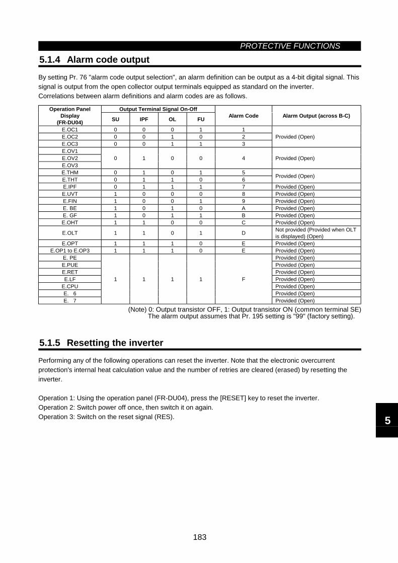
PROTECTIVE FUNCTIONS
183
5.1.4 Alarm code output
By setting Pr. 76 "alarm code output selection", an alarm definition can be output as a 4-bit digital signal. Thissignal is output from the open collector output terminals equipped as standard on the inverter.Correlations between alarm definitions and alarm codes are as follows.
Output Terminal Signal On-OffOperation PanelDisplay
(FR-DU04) SU IPF OL FU Alarm Code Alarm Output (across B-C)
E.OC1 0 0 0 1 1E.OC2 0 0 1 0 2E.OC3 0 0 1 1 3
Provided (Open)
E.OV1E.OV2E.OV3
0 1 0 0 4 Provided (Open)
E.THM 0 1 0 1 5E.THT 0 1 1 0 6 Provided (Open)
E.IPF 0 1 1 1 7 Provided (Open)E.UVT 1 0 0 0 8 Provided (Open)E.FIN 1 0 0 1 9 Provided (Open)E. BE 1 0 1 0 A Provided (Open)E. GF 1 0 1 1 B Provided (Open)E.OHT 1 1 0 0 C Provided (Open)
E.OLT 1 1 0 1 D Not provided (Provided when OLTis displayed) (Open)
E.OPT 1 1 1 0 E Provided (Open)E.OP1 to E.OP3 1 1 1 0 E Provided (Open)
E. PE Provided (Open)E.PUE Provided (Open)E.RET Provided (Open)E.LF Provided (Open)
E.CPU Provided (Open)E. 6 Provided (Open)E. 7
1 1 1 1 F
Provided (Open)
(Note) 0: Output transistor OFF, 1: Output transistor ON (common terminal SE)The alarm output assumes that Pr. 195 setting is "99" (factory setting).
5.1.5 Resetting the inverter
Performing any of the following operations can reset the inverter. Note that the electronic overcurrentprotection's internal heat calculation value and the number of retries are cleared (erased) by resetting theinverter.
Operation 1: Using the operation panel (FR-DU04), press the [RESET] key to reset the inverter.Operation 2: Switch power off once, then switch it on again.Operation 3: Switch on the reset signal (RES). 5
5.2 TroubleshootingPROTECTIVE FUNCTIONS
184
5.2 Troubleshooting
POINT: Check the corresponding areas. If the cause is still unknown, it is recommended to initialize theparameters (return to factory settings), re-set the required parameter values, and check again.
5.2.1 Motor remains stopped1) Check the main circuit
• Check that a proper power supply voltage is applied (operation panel display is provided).• Check that the motor is connected properly.• Check that the conductor across P1-P is connected.
2) Check the input signals• Check that the start signal is input.• Check that both the forward and reverse rotation start signals are not input.• Check that the frequency setting signal is not zero.• Check that the AU signal is on when the frequency setting signal is 4 to 20mA.• Check that the output stop signal (MRS) or reset signal (RES) is not on.• Check that the CS signal is not off when automatic restart after instantaneous power failure is selected (Pr. 57 = other than "9999").
3) Check the parameter settings• Check that the reverse rotation prevention (Pr. 78) is not selected.• Check that the operation mode (Pr. 79) setting is correct.• Check that the bias and gain (Pr. 902 to Pr. 905) settings are correct.• Check that the starting frequency (Pr. 13) setting is not greater than the running frequency.• Check that various operational functions (such as three-speed operation), especially the maximum frequency (Pr. 1), are not zero.
4) Check the load• Check that the load is not too heavy.• Check that the shaft is not locked.
5) Others• Check that the ALARM lamp is not lit.• Check that the Pr. 15 "jog frequency" setting is not lower than the Pr. 13 "starting frequency" value.
5.2.2 Motor rotates in opposite direction• Check that the phase sequence of output terminals U, V and W is correct.• Check that the start signals (forward rotation, reverse rotation) are connected properly.
5.2.3 Speed greatly differs from the setting• Check that the frequency setting signal is correct. (Measure the input signal level.)• Check that the following parameter settings are proper: Pr. 1, Pr. 2, Pr. 902 to Pr. 905.• Check that the input signal lines are not affected by external noise. (Use shielded cables)• Check that the load is not too heavy.
5.2.4 Acceleration/deceleration is not smooth• Check that the acceleration and deceleration time settings are not too short.• Check that the load is not too heavy.
5.2.5 Motor current is large• Check that the load is not too heavy.
PROTECTIVE FUNCTIONS
185
5.2.6 Speed does not increase• Check that the maximum frequency (Pr. 1) setting is correct.• Check that the load is not too heavy. (In agitators, etc., load may become heavy in winter.)• Check that the brake resistor is not connected to terminals P-P1 by mistake.
5.2.7 Speed varies during operation
1) Inspection of load• Check that the load is not varying.
2) Inspection of input signal• Check that the frequency setting signal is not varying.• Check that the frequency setting signal is not affected by induced noise.
3) Others• Check that the wiring length is correct in V/F control.• In the FR-B3 series, check that the settings of the applied motor capacity (Pr. 80) and the number of
applied motor poles (Pr. 81) are proper for the inverter capacity and motor capacity under advancedmagnetic flux vector control.
• In the FR-B3 series, check that the offline auto tuning (Pr. 96) setting is proper.
5.2.8 Operation mode is not changed properly
If the operation mode is not changed properly, check the following:1. External input signal ........Check that the STF or STR signal is off.
When it is on, the operation mode cannot be changed.2. Parameter setting ............Check the Pr. 79 setting.
When the setting of Pr. 79 "operation mode selection" is "0" (factory setting),switching input power on places the inverter in the external operation mode.Press the operation panel's [MODE] key three times and press the [UP] key(press the [PU] key for the parameter unit (FR-PU04)). This changes theexternal operation mode into the PU operation mode. For any other setting (1to 8), the operation mode is limited according to the setting.
5.2.9 Operation panel (FR-DU04) display is not provided• Make sure that the operation panel is connected securely with the inverter.
5.2.10 POWER lamp is not lit• Make sure that the wiring and installation are correct.
5.2.11 Parameter write cannot be performed• Make sure that operation is not being performed (signal STF or STR is not ON).• Make sure that you pressed the [SET] key ([WRITE] key) for longer than 1.5 seconds.• Make sure that you are not attempting to set the parameter outside the setting range.• Make sure that you are not attempting to set the parameter in the external operation mode.• Check Pr. 77 "parameter write disable selection".
5
5.3 Precautions for Maintenance and InspectionPROTECTIVE FUNCTIONS
186
5.3 Precautions for Maintenance and Inspection
The pressure-resistant, explosion-proof motor driving inverter is a static unit mainly consisting ofsemiconductor devices. Daily inspection must be performed to prevent any fault from occurring due toadverse influence by the operating environment, such as temperature, humidity, dust, dirt and vibration,changes in the parts with time, service life, and other factors.
5.3.1 Precautions for maintenance and inspectionFor some short time after the power is switched off, a high voltage remains in the smoothing capacitor. Whenaccessing the inverter for inspection, switch power off. When more than 10 minutes have elapsed, make surethat the voltage across the main circuit terminals P-N of the inverter is 30VDC or less using a tester, etc.
5.3.2 Check items(1) Daily inspections
• Check the following:1) Motor operation fault2) Improper installation environment3) Cooling system fault4) Unusual vibration and noise5) Unusual overheating and discoloration
• During operation, check the inverter input voltages using a tester.
(2) Cleaning
Always run the inverter in a clean state.When cleaning the inverter, gently wipe dirty areas with a soft cloth immersed in neutral detergent or ethanol.
Note: Do not use solvent, such as acetone, benzene, toluene and alcohol, as they will cause the invertersurface paint to peel off.Do not use detergent or alcohol to clean the display and other sections of the operation panel (FR-DU04) or parameter unit (FR-PU04) as these sections do not like them.
5.3.3 Periodic inspectionCheck the areas inaccessible during operation and requiring periodic inspection. For periodic inspection,consult us.1) Cooling system: .....................Clean the air filter, etc.2) Screws and bolts: ..................These parts may become loose due to vibration, temperature changes, etc.
Check that they are tightened securely and retighten as necessary.3) Conductors and insulating materials: Check for corrosion and damage.4) Insulation resistance: Measure.5) Cooling fan, smoothing capacitor, relay: Check and change if necessary.
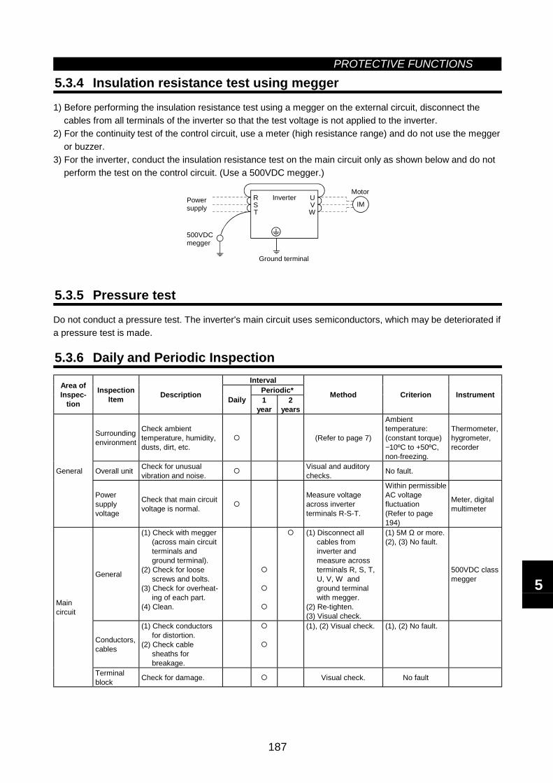
PROTECTIVE FUNCTIONS
187
5.3.4 Insulation resistance test using megger
1) Before performing the insulation resistance test using a megger on the external circuit, disconnect thecables from all terminals of the inverter so that the test voltage is not applied to the inverter.
2) For the continuity test of the control circuit, use a meter (high resistance range) and do not use the meggeror buzzer.
3) For the inverter, conduct the insulation resistance test on the main circuit only as shown below and do notperform the test on the control circuit. (Use a 500VDC megger.)
RST
UVW
IMInverter
MotorPowersupply
500VDCmegger
Ground terminal
5.3.5 Pressure test
Do not conduct a pressure test. The inverter's main circuit uses semiconductors, which may be deteriorated ifa pressure test is made.
5.3.6 Daily and Periodic InspectionInterval
Periodic*Area ofInspec-
tion
InspectionItem Description Daily 1
year2
years
Method Criterion Instrument
Surroundingenvironment
Check ambienttemperature, humidity,dusts, dirt, etc.
(Refer to page 7)
Ambienttemperature:(constant torque)−10ºC to +50ºC,non-freezing.
Thermometer,hygrometer,recorder
Overall unit Check for unusualvibration and noise.
Visual and auditorychecks. No fault.General
Powersupplyvoltage
Check that main circuitvoltage is normal.
Measure voltageacross inverterterminals R-S-T.
Within permissibleAC voltagefluctuation(Refer to page194)
Meter, digitalmultimeter
General
(1) Check with megger(across main circuitterminals andground terminal).
(2) Check for loosescrews and bolts.
(3) Check for overheat-ing of each part.
(4) Clean.
(1) Disconnect allcables frominverter andmeasure acrossterminals R, S, T,U, V, W andground terminalwith megger.
(2) Re-tighten.(3) Visual check.
(1) 5M Ω or more.(2), (3) No fault.
500VDC classmegger
Conductors,cables
(1) Check conductorsfor distortion.
(2) Check cablesheaths forbreakage.
(1), (2) Visual check. (1), (2) No fault.
Maincircuit
Terminalblock Check for damage. Visual check. No fault
5
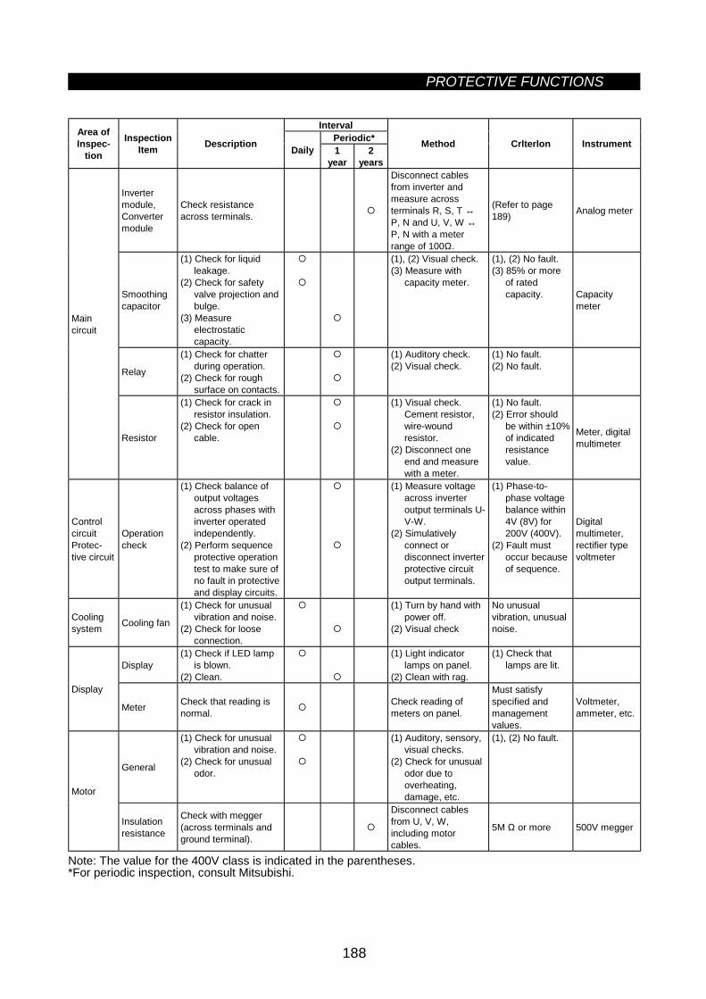
PROTECTIVE FUNCTIONS
188
IntervalPeriodic*Area of
Inspec-tion
InspectionItem Description Daily 1
year2
years
Method Crlterlon Instrument
Invertermodule,Convertermodule
Check resistanceacross terminals.
Disconnect cablesfrom inverter andmeasure acrossterminals R, S, T ↔P, N and U, V, W ↔P, N with a meterrange of 100Ω.
(Refer to page189) Analog meter
Smoothingcapacitor
(1) Check for liquidleakage.
(2) Check for safetyvalve projection andbulge.
(3) Measureelectrostaticcapacity.
(1), (2) Visual check.(3) Measure with
capacity meter.
(1), (2) No fault.(3) 85% or more
of ratedcapacity. Capacity
meter
Relay
(1) Check for chatterduring operation.
(2) Check for roughsurface on contacts.
(1) Auditory check.(2) Visual check.
(1) No fault.(2) No fault.
Maincircuit
Resistor
(1) Check for crack inresistor insulation.
(2) Check for opencable.
(1) Visual check.Cement resistor,wire-woundresistor.
(2) Disconnect oneend and measurewith a meter.
(1) No fault.(2) Error should
be within ±10%of indicatedresistancevalue.
Meter, digitalmultimeter
ControlcircuitProtec-tive circuit
Operationcheck
(1) Check balance ofoutput voltagesacross phases withinverter operatedindependently.
(2) Perform sequenceprotective operationtest to make sure ofno fault in protectiveand display circuits.
(1) Measure voltageacross inverteroutput terminals U-V-W.
(2) Simulativelyconnect ordisconnect inverterprotective circuitoutput terminals.
(1) Phase-to-phase voltagebalance within4V (8V) for200V (400V).
(2) Fault mustoccur becauseof sequence.
Digitalmultimeter,rectifier typevoltmeter
Coolingsystem Cooling fan
(1) Check for unusualvibration and noise.
(2) Check for looseconnection.
(1) Turn by hand withpower off.
(2) Visual check
No unusualvibration, unusualnoise.
Display(1) Check if LED lamp
is blown.(2) Clean.
(1) Light indicatorlamps on panel.
(2) Clean with rag.
(1) Check thatlamps are lit.
Display
Meter Check that reading isnormal.
Check reading ofmeters on panel.
Must satisfyspecified andmanagementvalues.
Voltmeter,ammeter, etc.
General
(1) Check for unusualvibration and noise.
(2) Check for unusualodor.
(1) Auditory, sensory,visual checks.
(2) Check for unusualodor due tooverheating,damage, etc.
(1), (2) No fault.
Motor
Insulationresistance
Check with megger(across terminals andground terminal).
Disconnect cablesfrom U, V, W,including motorcables.
5M Ω or more 500V megger
Note: The value for the 400V class is indicated in the parentheses.*For periodic inspection, consult Mitsubishi.
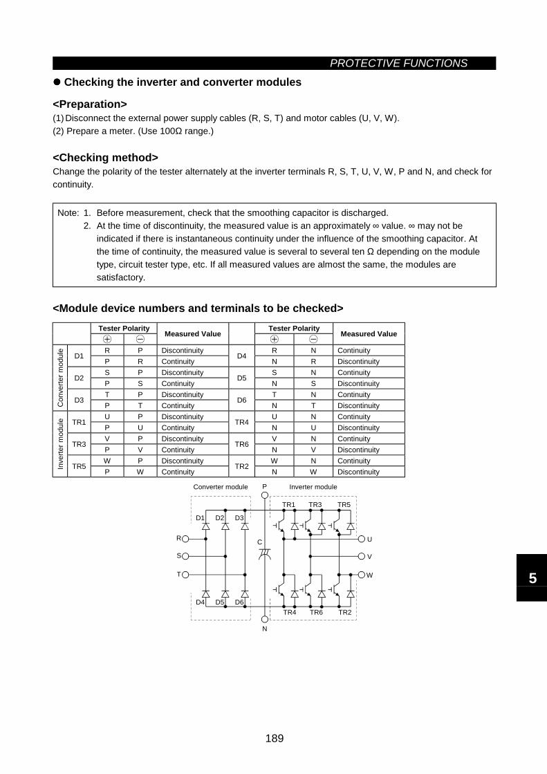
PROTECTIVE FUNCTIONS
189
Checking the inverter and converter modules
<Preparation>(1) Disconnect the external power supply cables (R, S, T) and motor cables (U, V, W).(2) Prepare a meter. (Use 100Ω range.)
<Checking method>Change the polarity of the tester alternately at the inverter terminals R, S, T, U, V, W, P and N, and check forcontinuity.
Note: 1. Before measurement, check that the smoothing capacitor is discharged.2. At the time of discontinuity, the measured value is an approximately ∞ value. ∞ may not be
indicated if there is instantaneous continuity under the influence of the smoothing capacitor. Atthe time of continuity, the measured value is several to several ten Ω depending on the moduletype, circuit tester type, etc. If all measured values are almost the same, the modules aresatisfactory.
<Module device numbers and terminals to be checked>Tester Polarity Tester Polarity
Measured Value Measured Value
R P Discontinuity R N ContinuityD1
P R ContinuityD4
N R DiscontinuityS P Discontinuity S N Continuity
D2P S Continuity
D5N S Discontinuity
T P Discontinuity T N Continuity
Con
verte
r mod
ule
D3P T Continuity
D6N T Discontinuity
U P Discontinuity U N ContinuityTR1
P U ContinuityTR4
N U DiscontinuityV P Discontinuity V N Continuity
TR3P V Continuity
TR6N V Discontinuity
W P Discontinuity W N Continuity
Inve
rter m
odul
e
TR5P W Continuity
TR2N W Discontinuity
D1 D2 D3
D4 D5 D6
TR1 TR3 TR5
TR4 TR6 TR2
U
V
W
R
S
T
C
P
N
Inverter moduleConverter module
5
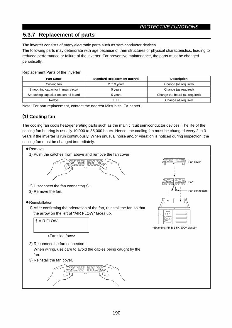
PROTECTIVE FUNCTIONS
190
5.3.7 Replacement of parts
The inverter consists of many electronic parts such as semiconductor devices.The following parts may deteriorate with age because of their structures or physical characteristics, leading toreduced performance or failure of the inverter. For preventive maintenance, the parts must be changedperiodically.
Replacement Parts of the InverterPart Name Standard Replacement Interval DescriptionCooling fan 2 to 3 years Change (as required)
Smoothing capacitor in main circuit 5 years Change (as required)Smoothing capacitor on control board 5 years Change the board (as required)
Relays Change as required
Note: For part replacement, contact the nearest Mitsubishi FA center.
(1) Cooling fan
The cooling fan cools heat-generating parts such as the main circuit semiconductor devices. The life of thecooling fan bearing is usually 10,000 to 35,000 hours. Hence, the cooling fan must be changed every 2 to 3years if the inverter is run continuously. When unusual noise and/or vibration is noticed during inspection, thecooling fan must be changed immediately.
Removal1) Push the catches from above and remove the fan cover.
2) Disconnect the fan connector(s).3) Remove the fan.
Reinstallation1) After confirming the orientation of the fan, reinstall the fan so that the arrow on the left of "AIR FLOW" faces up.
AIR FLOW
<Fan side face>
2) Reconnect the fan connectors.When wiring, use care to avoid the cables being caught by thefan.
3) Reinstall the fan cover.
Fan cover
Fan
Fan connectors
<Example: FR-B-5.5K(200V class)>
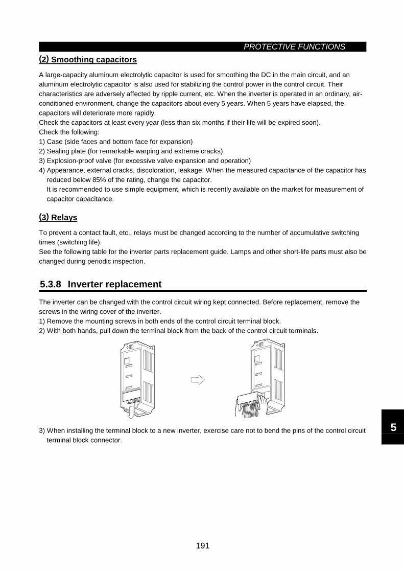
PROTECTIVE FUNCTIONS
191
(2) Smoothing capacitors
A large-capacity aluminum electrolytic capacitor is used for smoothing the DC in the main circuit, and analuminum electrolytic capacitor is also used for stabilizing the control power in the control circuit. Theircharacteristics are adversely affected by ripple current, etc. When the inverter is operated in an ordinary, air-conditioned environment, change the capacitors about every 5 years. When 5 years have elapsed, thecapacitors will deteriorate more rapidly.Check the capacitors at least every year (less than six months if their life will be expired soon).Check the following:1) Case (side faces and bottom face for expansion)2) Sealing plate (for remarkable warping and extreme cracks)3) Explosion-proof valve (for excessive valve expansion and operation)4) Appearance, external cracks, discoloration, leakage. When the measured capacitance of the capacitor has
reduced below 85% of the rating, change the capacitor.It is recommended to use simple equipment, which is recently available on the market for measurement ofcapacitor capacitance.
(3) Relays
To prevent a contact fault, etc., relays must be changed according to the number of accumulative switchingtimes (switching life).See the following table for the inverter parts replacement guide. Lamps and other short-life parts must also bechanged during periodic inspection.
5.3.8 Inverter replacementThe inverter can be changed with the control circuit wiring kept connected. Before replacement, remove thescrews in the wiring cover of the inverter.1) Remove the mounting screws in both ends of the control circuit terminal block.2) With both hands, pull down the terminal block from the back of the control circuit terminals.
3) When installing the terminal block to a new inverter, exercise care not to bend the pins of the control circuitterminal block connector.
5
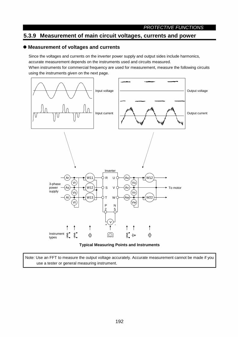
PROTECTIVE FUNCTIONS
192
5.3.9 Measurement of main circuit voltages, currents and power
Measurement of voltages and currentsSince the voltages and currents on the inverter power supply and output sides include harmonics,accurate measurement depends on the instruments used and circuits measured.When instruments for commercial frequency are used for measurement, measure the following circuitsusing the instruments given on the next page.
+ -
Ar
As
At
Vr
Vs
Vt
W11
W12
W13
Au
Av
Aw
Vu
Vv
Vw
W12
W22
V
R
S
T
U
V
W
Inverter
P2
3-phasepowersupply
Instrumenttypes
Input voltage
Input current
Output voltage
Output current
To motor
N5
Typical Measuring Points and Instruments
Note: Use an FFT to measure the output voltage accurately. Accurate measurement cannot be made if youuse a tester or general measuring instrument.
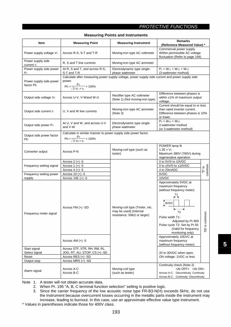
PROTECTIVE FUNCTIONS
193
Measuring Points and Instruments
Item Measuring Point Measuring Instrument Remarks(Reference Measured Value) *
Power supply voltage V1 Across R-S, S-T and T-R Moving-iron type AC voltmeterCommercial power supplyWithin permissible AC voltagefluctuation (Refer to page 194)
Power supply sidecurrent I1 R, S and T line currents Moving-iron type AC ammeter
Power supply side powerP1
At R, S and T, and across R-S,S-T and T-R
Electrodynamic type single-phase wattmeter
P1 = W11 + W12 + W13
(3-wattmeter method)
Power supply side powerfactor Pf1
Calculate after measuring power supply voltage, power supply side current and power supply sidepower.
× 100%3 V1 × I1
P1Pf1 =
Output side voltage V2 Across U-V, V-Wand W-U Rectifier type AC voltmeter(Note 1) (Not moving-iron type)
Difference between phases iswithin ±1% of maximum outputvoltage.
Output side current I2 U, V and W line currents Moving-iron type AC ammeter(Note 3)
Current should be equal to or lessthan rated inverter current.Difference between phases is 10%or lower.
Output side power P2At U, V and W, and across U-Vand V-W
Electrodynamic type single-phase wattmeter
P2 = W21 + W22
2-wattmeter method(or 3-wattmeter method)
Output side power factorPf2
Calculate in similar manner to power supply side power factor.
× 100%3 V2 × I2
P2Pf2 =
Converter output Across P-N Moving-coil type (such astester)
POWER lamp lit1.35 × V1
Maximum 380V (760V) duringregenerative operation
Across 2 (+) -5 0 to 5V/0 to 10VDCAcross 1 (+) -5 0 to ±5V/0 to ±10VDCFrequency setting signalAcross 4 (+) -5 4 to 20mADCAcross 10 (+) -5 5VDCFrequency setting power
supply Across 10E (+) -5 10VDC
“5” i
sco
mm
on.
Across FM (+) -SD
Approximately 5VDC atmaximum frequency(without frequency meter)
8VDC
T1
T2
Pulse width T1:Adjusted by Pr.900
Pulse cycle T2: Set by Pr.55(Valid for frequency
monitoring only)
Frequency meter signal
Across AM (+) -5Approximately 10DVC atmaximum frequency(without frequency meter)
Start signalSelect signal
Across STF, STR, RH, RM, RL,JOG, RT, AU, STOP, CS (+) -SD
Reset Across RES (+) -SDOutput stop Across MRS (+) -SD
Moving-coil type (Tester, etc.may be used) (Internalresistance: 50kΩ or larger)
20 to 30VDC when open.ON voltage: 1VDC or less
SD is
com
mon
.
Alarm signal Across A-CAcross B-C
Moving-coil type(such as tester)
Continuity check (Note 2)<At OFF> <At ON>
Across A-C: Discontinuity ContinuityAcross B-C: Continuity Discontinuity
Note 1. A tester will not obtain accurate data.2. When Pr. 195 "A, B, C terminal function selection" setting is positive logic.3. Since the carrier frequency of the low acoustic noise type FR-B3-N(H) exceeds 5kHz, do not use
the instrument because overcurrent losses occurring in the metallic parts inside the instrument mayincrease, leading to burnout. In this case, use an approximate effective value type instrument.
* Values in parentheses indicate those for 400V class.
5

MEMO
6
CHAPTER 6SPECIFICATIONS
This chapter provides the "specifications" of this product.Always read the instructions before using the equipment.
6.1 Standard Specifications ...........................................194
Chapter 1
Chapter 2
Chapter 3
Chapter 4
Chapter 5
Chapter 6
Chapter 7

6.1 Standard SpecificationsSPECIFICATIONS
194
6 SPECIFICATIONS6.1 Standard Specifications
6.1.1 Model specificationsFR-B series (most suitable for inverter-driven, variable-torque, pressure-resistant, explosion-proof motors)
200V classType FR-B- 750 (Note 8) 1500 2200 3700 5.5K 7.5K 11K 15K 22K 30K 37K 45K
Variable torquetype
0.2(Note
8)0.4 0.75 1.5 2.2 3.7 5.5 7.5 11 15 22 30 37 45
Applicablemotor capacity(kW) (Note 1) Constant
torque type 0.4 0.75 1.5 2.2 3.7 5.5 7.5 11 15 18.5 22 30 37
Rated capacity (kVA)(Note 2) 1.9 3.1 4.2 6.5 9.2 12.6 17.6 23.3 34 44 55 67
Continuous current (A) 5 8 11 17.5 24 33 46 61 90 115 145 175
Overload capacity (Note 3) 150% 60 s, 200% 0.5 s (inverse-time characteristics)
Voltage (Note 4) Three phase, 200V 50Hz, 220V 60Hz
Maximum value/time 150%/5 s 100%/5 s 20% (Note 5)
Out
put
Regen-erativebrakingtorque Permissible duty 3%ED 2%ED Continuous (Note 5)
Rated input AC voltage,frequency Three phase, 200V 50Hz, 200/220V 60Hz
Permissible AC voltagefluctuation 180 to 220V 50Hz, 180 to 242V 60Hz
Permissible frequencyfluctuation ±5%
Variabletorque type 0.8 1.5 2.5 4.5 5.5 9 12 17 20 28 41 52 66 80
Pow
er s
uppl
y
Power supplysystemcapacity (kVA)(Note 6) Constant
torque type 1.5 2.2 4.5 5.5 9 12 17 20 28 34 41 52 66
Protective structure (JEM 1030) Enclosed type (IP20) (Note 7) Open type (IP00)Cooling system Self-cooling Forced air coolingApprox. weight (kg), with DU 2.5 3.5 3.5 3.5 6.0 6.0 8.0 13.0 13.0 30.0 40.0 40.0
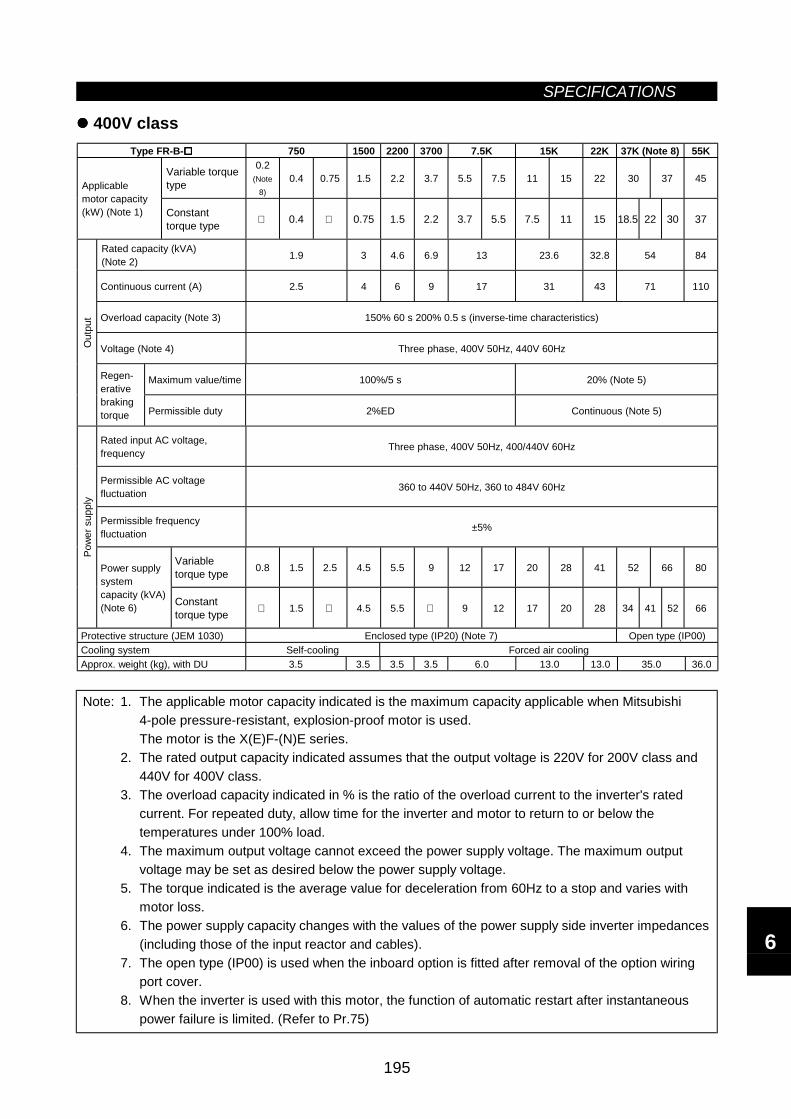
SPECIFICATIONS
195
400V classType FR-B- 750 1500 2200 3700 7.5K 15K 22K 37K (Note 8) 55K
Variable torquetype
0.2(Note
8)0.4 0.75 1.5 2.2 3.7 5.5 7.5 11 15 22 30 37 45
Applicablemotor capacity(kW) (Note 1) Constant
torque type 0.4 0.75 1.5 2.2 3.7 5.5 7.5 11 15 18.5 22 30 37
Rated capacity (kVA)(Note 2) 1.9 3 4.6 6.9 13 23.6 32.8 54 84
Continuous current (A) 2.5 4 6 9 17 31 43 71 110
Overload capacity (Note 3) 150% 60 s 200% 0.5 s (inverse-time characteristics)
Voltage (Note 4) Three phase, 400V 50Hz, 440V 60Hz
Maximum value/time 100%/5 s 20% (Note 5)
Out
put
Regen-erativebrakingtorque Permissible duty 2%ED Continuous (Note 5)
Rated input AC voltage,frequency Three phase, 400V 50Hz, 400/440V 60Hz
Permissible AC voltagefluctuation 360 to 440V 50Hz, 360 to 484V 60Hz
Permissible frequencyfluctuation ±5%
Variabletorque type 0.8 1.5 2.5 4.5 5.5 9 12 17 20 28 41 52 66 80
Pow
er s
uppl
y
Power supplysystemcapacity (kVA)(Note 6) Constant
torque type 1.5 4.5 5.5 9 12 17 20 28 34 41 52 66
Protective structure (JEM 1030) Enclosed type (IP20) (Note 7) Open type (IP00)Cooling system Self-cooling Forced air coolingApprox. weight (kg), with DU 3.5 3.5 3.5 3.5 6.0 13.0 13.0 35.0 36.0
Note: 1. The applicable motor capacity indicated is the maximum capacity applicable when Mitsubishi4-pole pressure-resistant, explosion-proof motor is used.The motor is the X(E)F-(N)E series.
2. The rated output capacity indicated assumes that the output voltage is 220V for 200V class and440V for 400V class.
3. The overload capacity indicated in % is the ratio of the overload current to the inverter's ratedcurrent. For repeated duty, allow time for the inverter and motor to return to or below thetemperatures under 100% load.
4. The maximum output voltage cannot exceed the power supply voltage. The maximum outputvoltage may be set as desired below the power supply voltage.
5. The torque indicated is the average value for deceleration from 60Hz to a stop and varies withmotor loss.
6. The power supply capacity changes with the values of the power supply side inverter impedances(including those of the input reactor and cables).
7. The open type (IP00) is used when the inboard option is fitted after removal of the option wiringport cover.
8. When the inverter is used with this motor, the function of automatic restart after instantaneouspower failure is limited. (Refer to Pr.75)
6
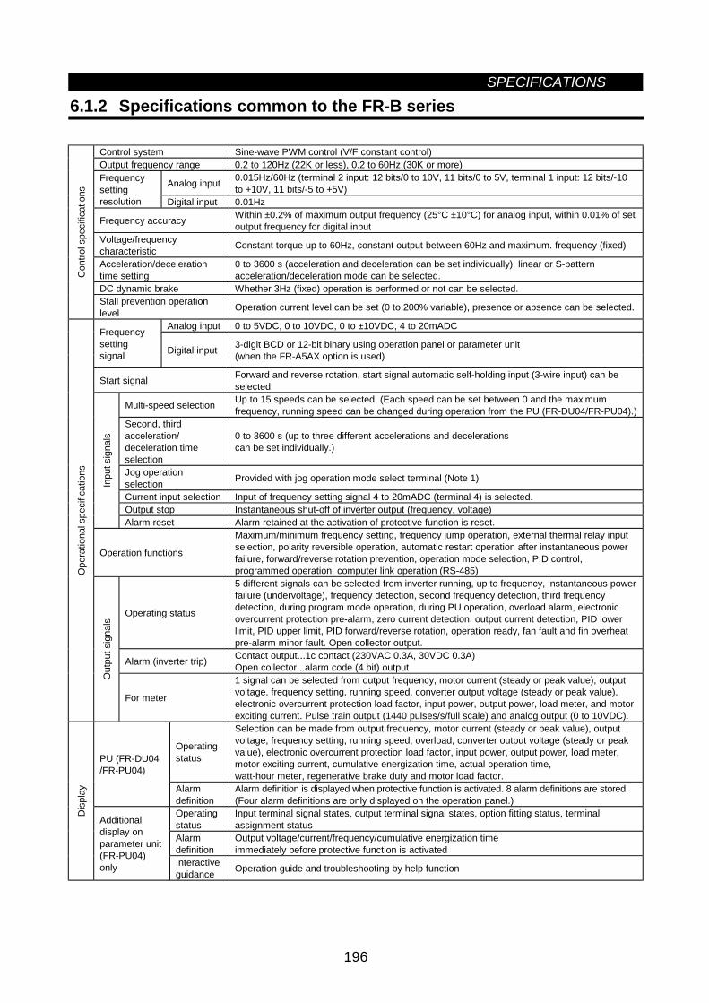
SPECIFICATIONS
196
6.1.2 Specifications common to the FR-B series
Control system Sine-wave PWM control (V/F constant control)Output frequency range 0.2 to 120Hz (22K or less), 0.2 to 60Hz (30K or more)
Analog input 0.015Hz/60Hz (terminal 2 input: 12 bits/0 to 10V, 11 bits/0 to 5V, terminal 1 input: 12 bits/-10to +10V, 11 bits/-5 to +5V)
Frequencysettingresolution Digital input 0.01Hz
Frequency accuracy Within ±0.2% of maximum output frequency (25°C ±10°C) for analog input, within 0.01% of setoutput frequency for digital input
Voltage/frequencycharacteristic Constant torque up to 60Hz, constant output between 60Hz and maximum. frequency (fixed)
Acceleration/decelerationtime setting
0 to 3600 s (acceleration and deceleration can be set individually), linear or S-patternacceleration/deceleration mode can be selected.
DC dynamic brake Whether 3Hz (fixed) operation is performed or not can be selected.
Con
trol s
peci
ficat
ions
Stall prevention operationlevel Operation current level can be set (0 to 200% variable), presence or absence can be selected.
Analog input 0 to 5VDC, 0 to 10VDC, 0 to ±10VDC, 4 to 20mADCFrequencysettingsignal Digital input 3-digit BCD or 12-bit binary using operation panel or parameter unit
(when the FR-A5AX option is used)
Start signal Forward and reverse rotation, start signal automatic self-holding input (3-wire input) can beselected.
Multi-speed selection Up to 15 speeds can be selected. (Each speed can be set between 0 and the maximumfrequency, running speed can be changed during operation from the PU (FR-DU04/FR-PU04).)
Second, thirdacceleration/deceleration timeselection
0 to 3600 s (up to three different accelerations and decelerationscan be set individually.)
Jog operationselection Provided with jog operation mode select terminal (Note 1)
Current input selection Input of frequency setting signal 4 to 20mADC (terminal 4) is selected.Output stop Instantaneous shut-off of inverter output (frequency, voltage)
Inpu
t sig
nals
Alarm reset Alarm retained at the activation of protective function is reset.
Operation functions
Maximum/minimum frequency setting, frequency jump operation, external thermal relay inputselection, polarity reversible operation, automatic restart operation after instantaneous powerfailure, forward/reverse rotation prevention, operation mode selection, PID control,programmed operation, computer link operation (RS-485)
Operating status
5 different signals can be selected from inverter running, up to frequency, instantaneous powerfailure (undervoltage), frequency detection, second frequency detection, third frequencydetection, during program mode operation, during PU operation, overload alarm, electronicovercurrent protection pre-alarm, zero current detection, output current detection, PID lowerlimit, PID upper limit, PID forward/reverse rotation, operation ready, fan fault and fin overheatpre-alarm minor fault. Open collector output.
Alarm (inverter trip) Contact output...1c contact (230VAC 0.3A, 30VDC 0.3A)Open collector...alarm code (4 bit) output
Ope
ratio
nal s
peci
ficat
ions
Out
put s
igna
ls
For meter
1 signal can be selected from output frequency, motor current (steady or peak value), outputvoltage, frequency setting, running speed, converter output voltage (steady or peak value),electronic overcurrent protection load factor, input power, output power, load meter, and motorexciting current. Pulse train output (1440 pulses/s/full scale) and analog output (0 to 10VDC).
Operatingstatus
Selection can be made from output frequency, motor current (steady or peak value), outputvoltage, frequency setting, running speed, overload, converter output voltage (steady or peakvalue), electronic overcurrent protection load factor, input power, output power, load meter,motor exciting current, cumulative energization time, actual operation time,watt-hour meter, regenerative brake duty and motor load factor.
PU (FR-DU04/FR-PU04)
Alarmdefinition
Alarm definition is displayed when protective function is activated. 8 alarm definitions are stored.(Four alarm definitions are only displayed on the operation panel.)
Operatingstatus
Input terminal signal states, output terminal signal states, option fitting status, terminalassignment status
Alarmdefinition
Output voltage/current/frequency/cumulative energization timeimmediately before protective function is activated
Dis
play
Additionaldisplay onparameter unit(FR-PU04)only Interactive
guidance Operation guide and troubleshooting by help function
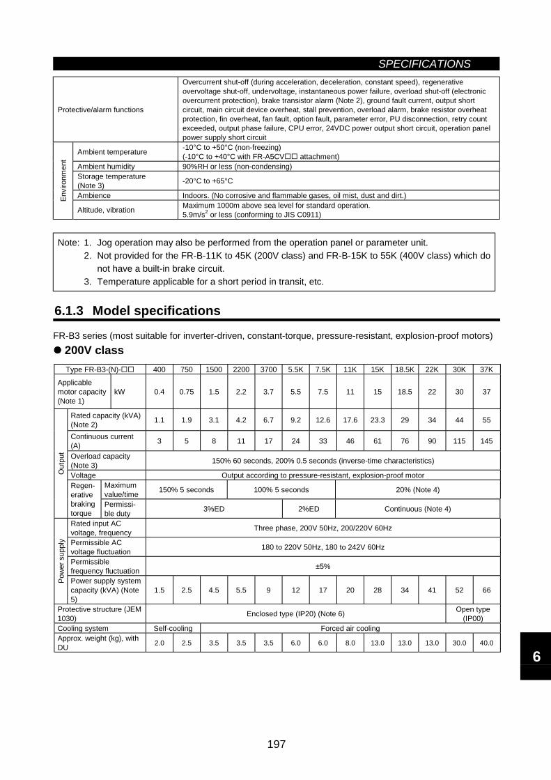
SPECIFICATIONS
197
Protective/alarm functions
Overcurrent shut-off (during acceleration, deceleration, constant speed), regenerativeovervoltage shut-off, undervoltage, instantaneous power failure, overload shut-off (electronicovercurrent protection), brake transistor alarm (Note 2), ground fault current, output shortcircuit, main circuit device overheat, stall prevention, overload alarm, brake resistor overheatprotection, fin overheat, fan fault, option fault, parameter error, PU disconnection, retry countexceeded, output phase failure, CPU error, 24VDC power output short circuit, operation panelpower supply short circuit
Ambient temperature -10°C to +50°C (non-freezing)(-10°C to +40°C with FR-A5CV attachment)
Ambient humidity 90%RH or less (non-condensing)Storage temperature(Note 3) -20°C to +65°C
Ambience Indoors. (No corrosive and flammable gases, oil mist, dust and dirt.)Envi
ronm
ent
Altitude, vibration Maximum 1000m above sea level for standard operation.5.9m/s2 or less (conforming to JIS C0911)
Note: 1. Jog operation may also be performed from the operation panel or parameter unit.2. Not provided for the FR-B-11K to 45K (200V class) and FR-B-15K to 55K (400V class) which do
not have a built-in brake circuit.3. Temperature applicable for a short period in transit, etc.
6.1.3 Model specifications
FR-B3 series (most suitable for inverter-driven, constant-torque, pressure-resistant, explosion-proof motors)200V classType FR-B3-(N)- 400 750 1500 2200 3700 5.5K 7.5K 11K 15K 18.5K 22K 30K 37K
Applicablemotor capacity(Note 1)
kW 0.4 0.75 1.5 2.2 3.7 5.5 7.5 11 15 18.5 22 30 37
Rated capacity (kVA)(Note 2) 1.1 1.9 3.1 4.2 6.7 9.2 12.6 17.6 23.3 29 34 44 55
Continuous current(A) 3 5 8 11 17 24 33 46 61 76 90 115 145
Overload capacity(Note 3) 150% 60 seconds, 200% 0.5 seconds (inverse-time characteristics)
Voltage Output according to pressure-resistant, explosion-proof motorMaximumvalue/time 150% 5 seconds 100% 5 seconds 20% (Note 4)
Out
put
Regen-erativebrakingtorque
Permissi-ble duty 3%ED 2%ED Continuous (Note 4)
Rated input ACvoltage, frequency Three phase, 200V 50Hz, 200/220V 60Hz
Permissible ACvoltage fluctuation 180 to 220V 50Hz, 180 to 242V 60Hz
Permissiblefrequency fluctuation ±5%
Pow
er s
uppl
y
Power supply systemcapacity (kVA) (Note5)
1.5 2.5 4.5 5.5 9 12 17 20 28 34 41 52 66
Protective structure (JEM1030) Enclosed type (IP20) (Note 6) Open type
(IP00)Cooling system Self-cooling Forced air coolingApprox. weight (kg), withDU 2.0 2.5 3.5 3.5 3.5 6.0 6.0 8.0 13.0 13.0 13.0 30.0 40.0
6
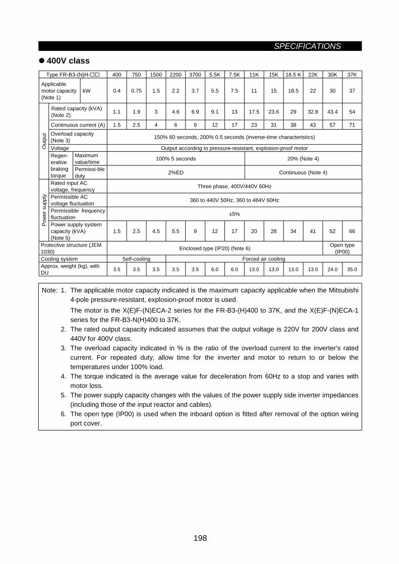
SPECIFICATIONS
198
400V classType FR-B3-(N)H- 400 750 1500 2200 3700 5.5K 7.5K 11K 15K 18.5 K 22K 30K 37K
Applicablemotor capacity(Note 1)
kW 0.4 0.75 1.5 2.2 3.7 5.5 7.5 11 15 18.5 22 30 37
Rated capacity (kVA)(Note 2) 1.1 1.9 3 4.6 6.9 9.1 13 17.5 23.6 29 32.8 43.4 54
Continuous current (A) 1.5 2.5 4 6 9 12 17 23 31 38 43 57 71Overload capacity(Note 3) 150% 60 seconds, 200% 0.5 seconds (inverse-time characteristics)
Voltage Output according to pressure-resistant, explosion-proof motorMaximumvalue/time 100% 5 seconds 20% (Note 4)
Out
put
Regen-erativebrakingtorque
Permissi-bleduty 2%ED Continuous (Note 4)
Rated input ACvoltage, frequency Three phase, 400V/440V 60Hz
Permissible ACvoltage fluctuation 360 to 440V 50Hz, 360 to 484V 60Hz
Permissible frequencyfluctuation ±5%
Pow
er s
uppl
y
Power supply systemcapacity (kVA)(Note 5)
1.5 2.5 4.5 5.5 9 12 17 20 28 34 41 52 66
Protective structure (JEM1030) Enclosed type (IP20) (Note 6) Open type
(IP00)Cooling system Self-cooling Forced air coolingApprox. weight (kg), withDU 3.5 3.5 3.5 3.5 3.5 6.0 6.0 13.0 13.0 13.0 13.0 24.0 35.0
Note: 1. The applicable motor capacity indicated is the maximum capacity applicable when the Mitsubishi4-pole pressure-resistant, explosion-proof motor is used.The motor is the X(E)F-(N)ECA-2 series for the FR-B3-(H)400 to 37K, and the X(E)F-(N)ECA-1series for the FR-B3-N(H)400 to 37K.
2. The rated output capacity indicated assumes that the output voltage is 220V for 200V class and440V for 400V class.
3. The overload capacity indicated in % is the ratio of the overload current to the inverter's ratedcurrent. For repeated duty, allow time for the inverter and motor to return to or below thetemperatures under 100% load.
4. The torque indicated is the average value for deceleration from 60Hz to a stop and varies withmotor loss.
5. The power supply capacity changes with the values of the power supply side inverter impedances(including those of the input reactor and cables).
6. The open type (IP00) is used when the inboard option is fitted after removal of the option wiringport cover.
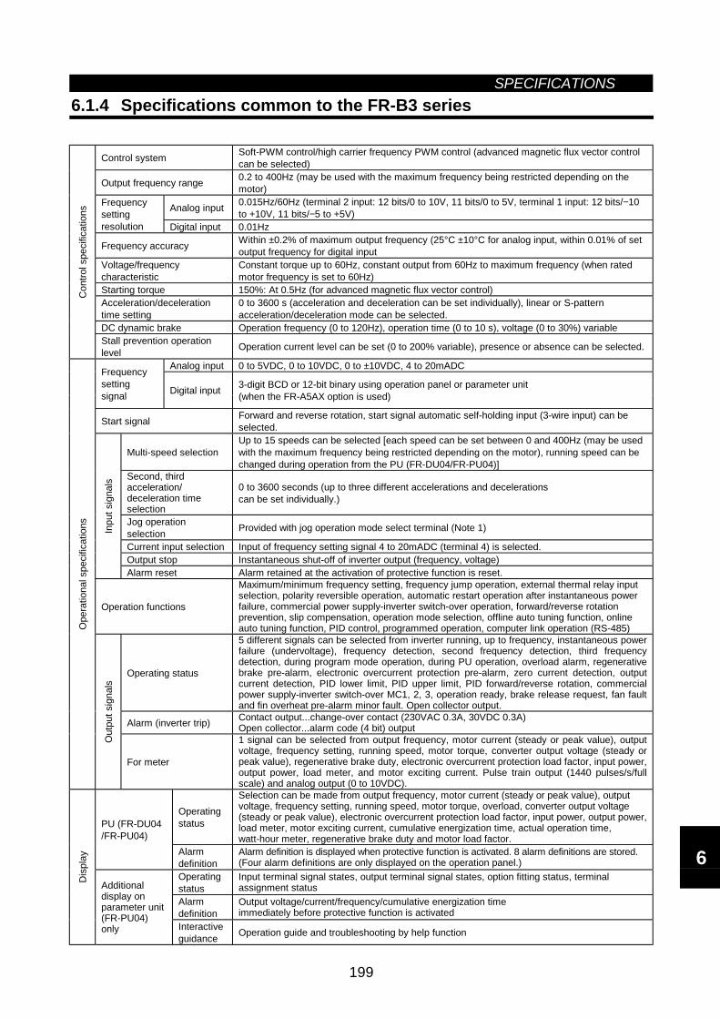
SPECIFICATIONS
199
6.1.4 Specifications common to the FR-B3 series
Control system Soft-PWM control/high carrier frequency PWM control (advanced magnetic flux vector controlcan be selected)
Output frequency range 0.2 to 400Hz (may be used with the maximum frequency being restricted depending on themotor)
Analog input 0.015Hz/60Hz (terminal 2 input: 12 bits/0 to 10V, 11 bits/0 to 5V, terminal 1 input: 12 bits/−10to +10V, 11 bits/−5 to +5V)
Frequencysettingresolution Digital input 0.01Hz
Frequency accuracy Within ±0.2% of maximum output frequency (25°C ±10°C for analog input, within 0.01% of setoutput frequency for digital input
Voltage/frequencycharacteristic
Constant torque up to 60Hz, constant output from 60Hz to maximum frequency (when ratedmotor frequency is set to 60Hz)
Starting torque 150%: At 0.5Hz (for advanced magnetic flux vector control)Acceleration/decelerationtime setting
0 to 3600 s (acceleration and deceleration can be set individually), linear or S-patternacceleration/deceleration mode can be selected.
DC dynamic brake Operation frequency (0 to 120Hz), operation time (0 to 10 s), voltage (0 to 30%) variable
Con
trol s
peci
ficat
ions
Stall prevention operationlevel Operation current level can be set (0 to 200% variable), presence or absence can be selected.
Analog input 0 to 5VDC, 0 to 10VDC, 0 to ±10VDC, 4 to 20mADCFrequencysettingsignal Digital input 3-digit BCD or 12-bit binary using operation panel or parameter unit
(when the FR-A5AX option is used)
Start signal Forward and reverse rotation, start signal automatic self-holding input (3-wire input) can beselected.
Multi-speed selectionUp to 15 speeds can be selected [each speed can be set between 0 and 400Hz (may be usedwith the maximum frequency being restricted depending on the motor), running speed can bechanged during operation from the PU (FR-DU04/FR-PU04)]
Second, thirdacceleration/deceleration timeselection
0 to 3600 seconds (up to three different accelerations and decelerationscan be set individually.)
Jog operationselection Provided with jog operation mode select terminal (Note 1)
Current input selection Input of frequency setting signal 4 to 20mADC (terminal 4) is selected.Output stop Instantaneous shut-off of inverter output (frequency, voltage)
Inpu
t sig
nals
Alarm reset Alarm retained at the activation of protective function is reset.
Operation functions
Maximum/minimum frequency setting, frequency jump operation, external thermal relay inputselection, polarity reversible operation, automatic restart operation after instantaneous powerfailure, commercial power supply-inverter switch-over operation, forward/reverse rotationprevention, slip compensation, operation mode selection, offline auto tuning function, onlineauto tuning function, PID control, programmed operation, computer link operation (RS-485)
Operating status
5 different signals can be selected from inverter running, up to frequency, instantaneous powerfailure (undervoltage), frequency detection, second frequency detection, third frequencydetection, during program mode operation, during PU operation, overload alarm, regenerativebrake pre-alarm, electronic overcurrent protection pre-alarm, zero current detection, outputcurrent detection, PID lower limit, PID upper limit, PID forward/reverse rotation, commercialpower supply-inverter switch-over MC1, 2, 3, operation ready, brake release request, fan faultand fin overheat pre-alarm minor fault. Open collector output.
Alarm (inverter trip) Contact output...change-over contact (230VAC 0.3A, 30VDC 0.3A)Open collector...alarm code (4 bit) output
Ope
ratio
nal s
peci
ficat
ions
Out
put s
igna
ls
For meter
1 signal can be selected from output frequency, motor current (steady or peak value), outputvoltage, frequency setting, running speed, motor torque, converter output voltage (steady orpeak value), regenerative brake duty, electronic overcurrent protection load factor, input power,output power, load meter, and motor exciting current. Pulse train output (1440 pulses/s/fullscale) and analog output (0 to 10VDC).
Operatingstatus
Selection can be made from output frequency, motor current (steady or peak value), outputvoltage, frequency setting, running speed, motor torque, overload, converter output voltage(steady or peak value), electronic overcurrent protection load factor, input power, output power,load meter, motor exciting current, cumulative energization time, actual operation time,watt-hour meter, regenerative brake duty and motor load factor.
PU (FR-DU04/FR-PU04)
Alarmdefinition
Alarm definition is displayed when protective function is activated. 8 alarm definitions are stored.(Four alarm definitions are only displayed on the operation panel.)
Operatingstatus
Input terminal signal states, output terminal signal states, option fitting status, terminalassignment status
Alarmdefinition
Output voltage/current/frequency/cumulative energization timeimmediately before protective function is activated
Dis
play
Additionaldisplay onparameter unit(FR-PU04)only Interactive
guidance Operation guide and troubleshooting by help function
6
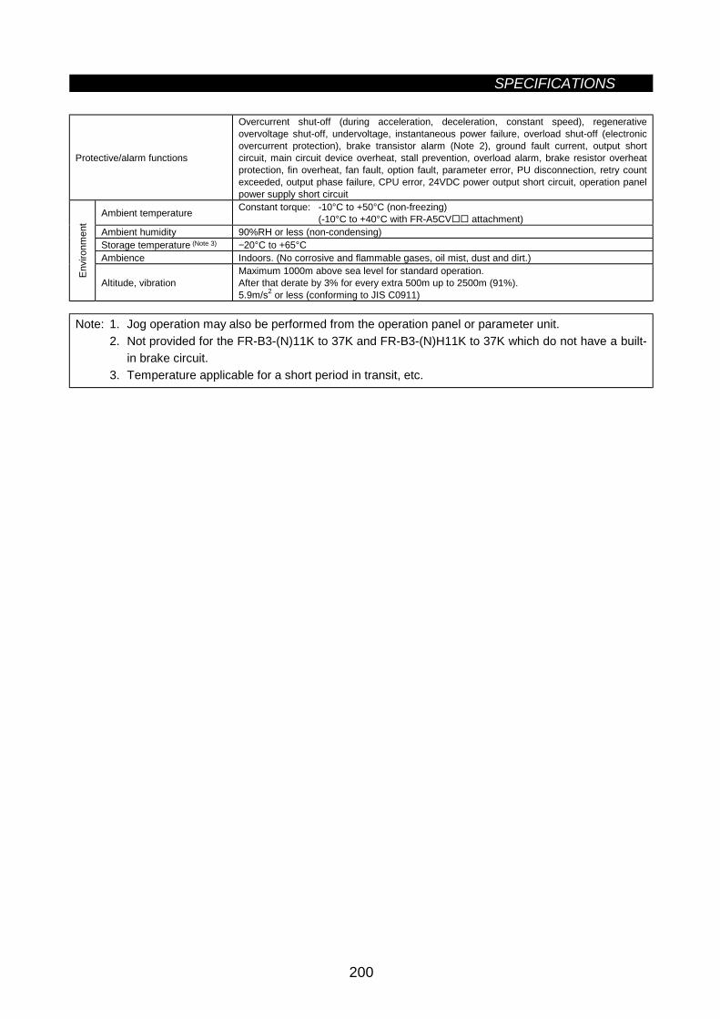
SPECIFICATIONS
200
Protective/alarm functions
Overcurrent shut-off (during acceleration, deceleration, constant speed), regenerativeovervoltage shut-off, undervoltage, instantaneous power failure, overload shut-off (electronicovercurrent protection), brake transistor alarm (Note 2), ground fault current, output shortcircuit, main circuit device overheat, stall prevention, overload alarm, brake resistor overheatprotection, fin overheat, fan fault, option fault, parameter error, PU disconnection, retry countexceeded, output phase failure, CPU error, 24VDC power output short circuit, operation panelpower supply short circuit
Ambient temperature Constant torque: -10°C to +50°C (non-freezing)(-10°C to +40°C with FR-A5CV attachment)
Ambient humidity 90%RH or less (non-condensing)Storage temperature (Note 3) −20°C to +65°CAmbience Indoors. (No corrosive and flammable gases, oil mist, dust and dirt.)
Envi
ronm
ent
Altitude, vibrationMaximum 1000m above sea level for standard operation.After that derate by 3% for every extra 500m up to 2500m (91%).5.9m/s2 or less (conforming to JIS C0911)
Note: 1. Jog operation may also be performed from the operation panel or parameter unit.2. Not provided for the FR-B3-(N)11K to 37K and FR-B3-(N)H11K to 37K which do not have a built-
in brake circuit.3. Temperature applicable for a short period in transit, etc.
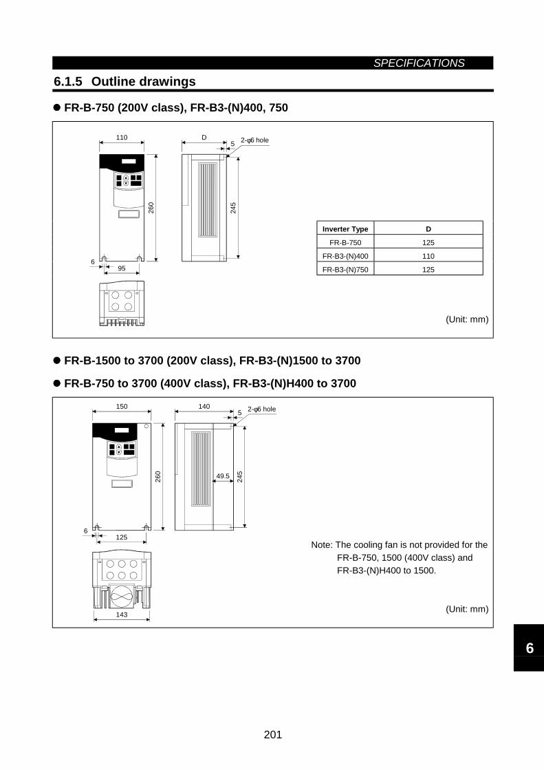
SPECIFICATIONS
201
6.1.5 Outline drawings
FR-B-750 (200V class), FR-B3-(N)400, 750
Inverter Type D
FR-B-750 125
FR-B3-(N)400 110
FR-B3-(N)750 125
D11026
0
956
5
245
2-φ6 hole
(Unit: mm)
FR-B-1500 to 3700 (200V class), FR-B3-(N)1500 to 3700
FR-B-750 to 3700 (400V class), FR-B3-(N)H400 to 3700
150
260
140
143
49.5
1256
5 2-φ6 hole
245
Note: The cooling fan is not provided for theFR-B-750, 1500 (400V class) andFR-B3-(N)H400 to 1500.
(Unit: mm)
6
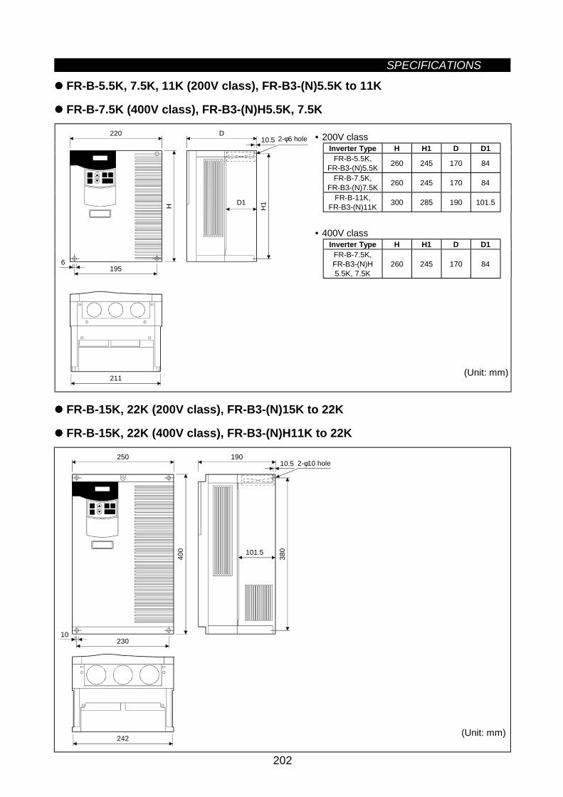
SPECIFICATIONS
202
FR-B-5.5K, 7.5K, 11K (200V class), FR-B3-(N)5.5K to 11K
FR-B-7.5K (400V class), FR-B3-(N)H5.5K, 7.5K
• 200V classInverter Type H H1 D D1
FR-B-5.5K,FR-B3-(N)5.5K 260 245 170 84
FR-B-7.5K,FR-B3-(N)7.5K 260 245 170 84
FR-B-11K,FR-B3-(N)11K 300 285 190 101.5
• 400V classInverter Type H H1 D D1
FR-B-7.5K,FR-B3-(N)H5.5K, 7.5K
260 245 170 84
220
H
D
211
1956
H1
10.5 2-φ6 hole
D1
(Unit: mm)
FR-B-15K, 22K (200V class), FR-B3-(N)15K to 22K
FR-B-15K, 22K (400V class), FR-B3-(N)H11K to 22K
250
400
190
242
230
380101.5
10.5
10
2-φ10 hole
(Unit: mm)
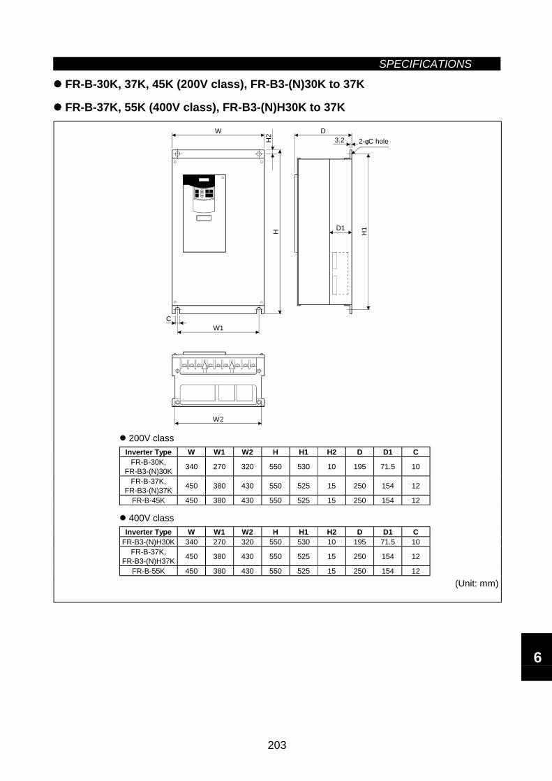
SPECIFICATIONS
203
FR-B-30K, 37K, 45K (200V class), FR-B3-(N)30K to 37K
FR-B-37K, 55K (400V class), FR-B3-(N)H30K to 37K
D1
CW1
H
W D3.2
H1
2-φC hole
W 2
H2
200V classInverter Type W W1 W2 H H1 H2 D D1 C
FR-B-30K,FR-B3-(N)30K 340 270 320 550 530 10 195 71.5 10
FR-B-37K,FR-B3-(N)37K 450 380 430 550 525 15 250 154 12
FR-B-45K 450 380 430 550 525 15 250 154 12
400V classInverter Type W W1 W2 H H1 H2 D D1 C
FR-B3-(N)H30K 340 270 320 550 530 10 195 71.5 10FR-B-37K,
FR-B3-(N)H37K 450 380 430 550 525 15 250 154 12
FR-B-55K 450 380 430 550 525 15 250 154 12
(Unit: mm)
6
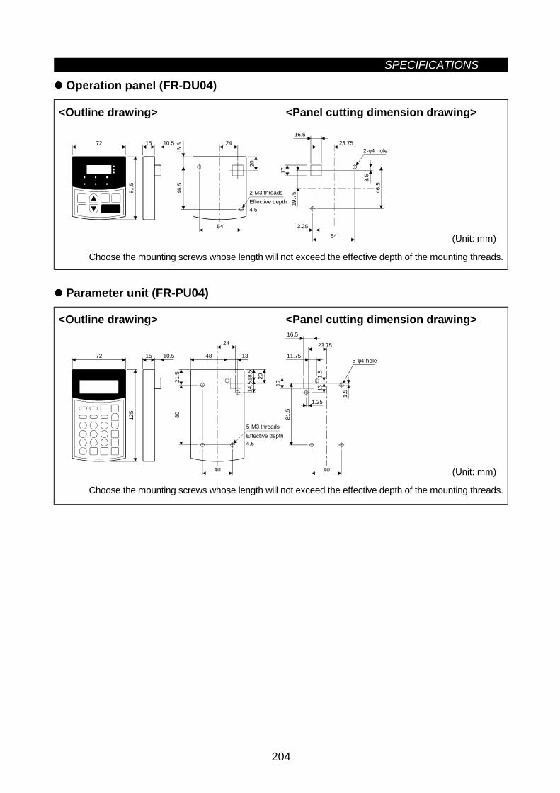
SPECIFICATIONS
204
Operation panel (FR-DU04)
<Outline drawing> <Panel cutting dimension drawing>
19.7
5
3.25
3.5
16.523.75
46.5
17
54
81.5
72 15 10.5
20
54
16.5
46.5
24
2-M3 threadsEffective depth 4.5
2-φ4 hole
(Unit: mm)
Choose the mounting screws whose length will not exceed the effective depth of the mounting threads.
Parameter unit (FR-PU04)
<Outline drawing> <Panel cutting dimension drawing>
40
23.75
11.75
81.5
1.25
1.5
13
17
16.51.
5
125
72 15 10.5
18.5
40
80
48
5-M3 threads
24
13
2021.5
14.5
Effective depth4.5
5-φ4 hole
(Unit: mm)
Choose the mounting screws whose length will not exceed the effective depth of the mounting threads.
7
CHAPTER 7OPTIONS
This chapter describes the "options" of this product.Always read the instructions before using the equipment.
7.1 Option List................................................................205
Chapter 1
Chapter 2
Chapter 3
Chapter 4
Chapter 5
Chapter 6
Chapter 7
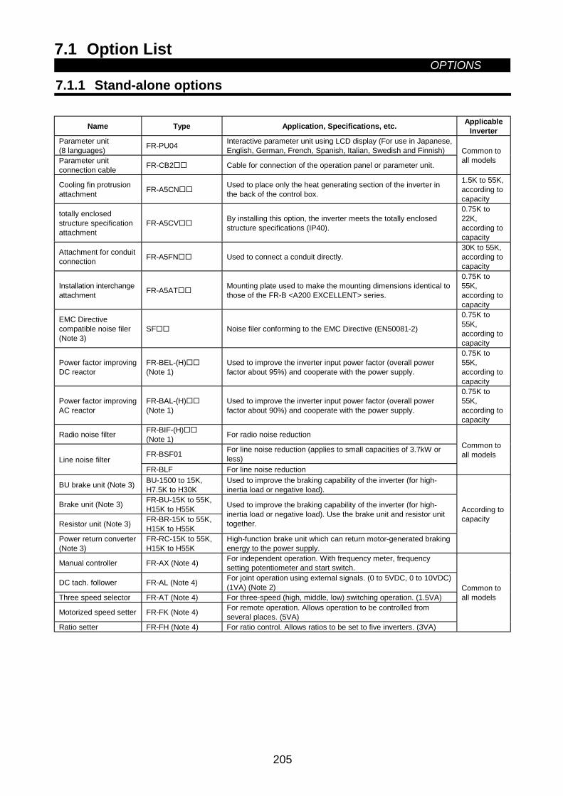
7.1 Option ListOPTIONS
205
7 OPTIONS7.1 Option List
7.1.1 Stand-alone options
Name Type Application, Specifications, etc. ApplicableInverter
Parameter unit(8 languages) FR-PU04 Interactive parameter unit using LCD display (For use in Japanese,
English, German, French, Spanish, Italian, Swedish and Finnish)Parameter unitconnection cable FR-CB2 Cable for connection of the operation panel or parameter unit.
Common toall models
Cooling fin protrusionattachment FR-A5CN Used to place only the heat generating section of the inverter in
the back of the control box.
1.5K to 55K,according tocapacity
totally enclosedstructure specificationattachment
FR-A5CV By installing this option, the inverter meets the totally enclosedstructure specifications (IP40).
0.75K to22K,according tocapacity
Attachment for conduitconnection FR-A5FN Used to connect a conduit directly.
30K to 55K,according tocapacity
Installation interchangeattachment FR-A5AT Mounting plate used to make the mounting dimensions identical to
those of the FR-B <A200 EXCELLENT> series.
0.75K to55K,according tocapacity
EMC Directivecompatible noise filer(Note 3)
SF Noise filer conforming to the EMC Directive (EN50081-2)
0.75K to55K,according tocapacity
Power factor improvingDC reactor
FR-BEL-(H)(Note 1)
Used to improve the inverter input power factor (overall powerfactor about 95%) and cooperate with the power supply.
0.75K to55K,according tocapacity
Power factor improvingAC reactor
FR-BAL-(H)(Note 1)
Used to improve the inverter input power factor (overall powerfactor about 90%) and cooperate with the power supply.
0.75K to55K,according tocapacity
Radio noise filter FR-BIF-(H)(Note 1) For radio noise reduction
FR-BSF01 For line noise reduction (applies to small capacities of 3.7kW orless)Line noise filter
FR-BLF For line noise reduction
Common toall models
BU brake unit (Note 3) BU-1500 to 15K,H7.5K to H30K
Used to improve the braking capability of the inverter (for high-inertia load or negative load).
Brake unit (Note 3) FR-BU-15K to 55K,H15K to H55K
Resistor unit (Note 3) FR-BR-15K to 55K,H15K to H55K
Used to improve the braking capability of the inverter (for high-inertia load or negative load). Use the brake unit and resistor unittogether.
Power return converter(Note 3)
FR-RC-15K to 55K,H15K to H55K
High-function brake unit which can return motor-generated brakingenergy to the power supply.
According tocapacity
Manual controller FR-AX (Note 4) For independent operation. With frequency meter, frequencysetting potentiometer and start switch.
DC tach. follower FR-AL (Note 4) For joint operation using external signals. (0 to 5VDC, 0 to 10VDC)(1VA) (Note 2)
Three speed selector FR-AT (Note 4) For three-speed (high, middle, low) switching operation. (1.5VA)
Motorized speed setter FR-FK (Note 4) For remote operation. Allows operation to be controlled fromseveral places. (5VA)
Ratio setter FR-FH (Note 4) For ratio control. Allows ratios to be set to five inverters. (3VA)
Common toall models
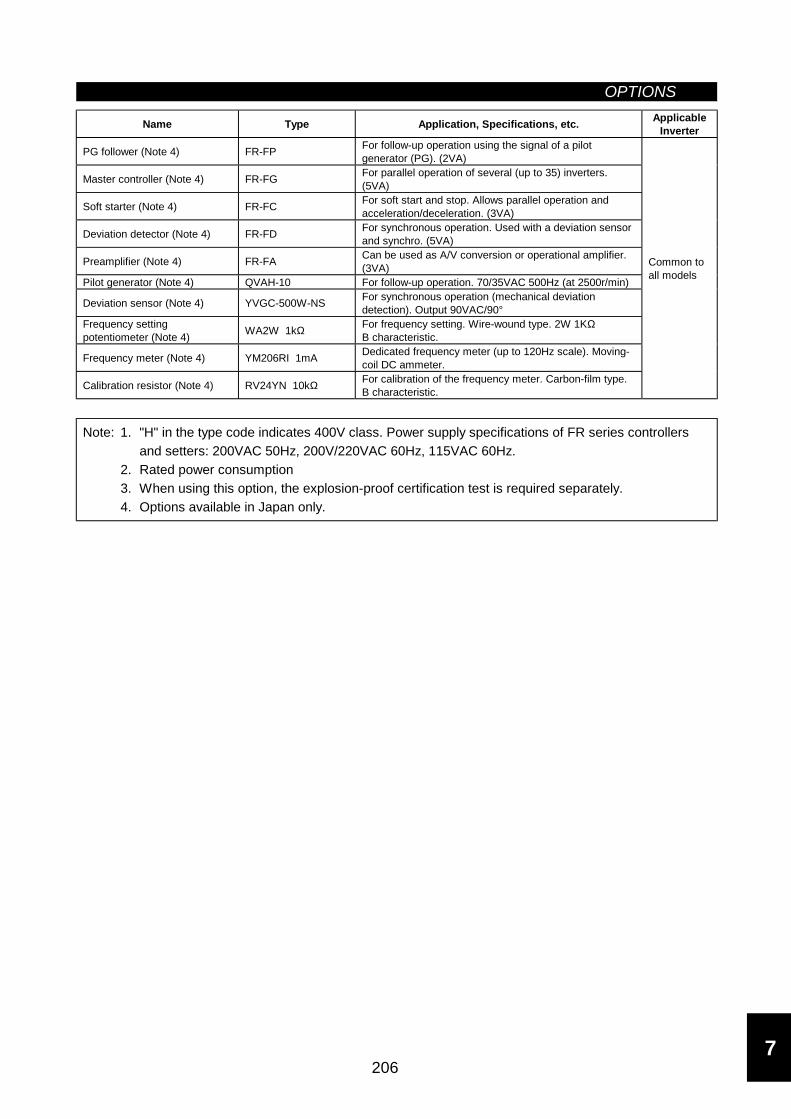
OPTIONS
206
Name Type Application, Specifications, etc. ApplicableInverter
PG follower (Note 4) FR-FP For follow-up operation using the signal of a pilotgenerator (PG). (2VA)
Master controller (Note 4) FR-FG For parallel operation of several (up to 35) inverters.(5VA)
Soft starter (Note 4) FR-FC For soft start and stop. Allows parallel operation andacceleration/deceleration. (3VA)
Deviation detector (Note 4) FR-FD For synchronous operation. Used with a deviation sensorand synchro. (5VA)
Preamplifier (Note 4) FR-FA Can be used as A/V conversion or operational amplifier.(3VA)
Pilot generator (Note 4) QVAH-10 For follow-up operation. 70/35VAC 500Hz (at 2500r/min)
Deviation sensor (Note 4) YVGC-500W-NS For synchronous operation (mechanical deviationdetection). Output 90VAC/90°
Frequency settingpotentiometer (Note 4) WA2W 1kΩ For frequency setting. Wire-wound type. 2W 1KΩ
B characteristic.
Frequency meter (Note 4) YM206RI 1mA Dedicated frequency meter (up to 120Hz scale). Moving-coil DC ammeter.
Calibration resistor (Note 4) RV24YN 10kΩ For calibration of the frequency meter. Carbon-film type.B characteristic.
Common toall models
Note: 1. "H" in the type code indicates 400V class. Power supply specifications of FR series controllersand setters: 200VAC 50Hz, 200V/220VAC 60Hz, 115VAC 60Hz.
2. Rated power consumption3. When using this option, the explosion-proof certification test is required separately.4. Options available in Japan only.
7
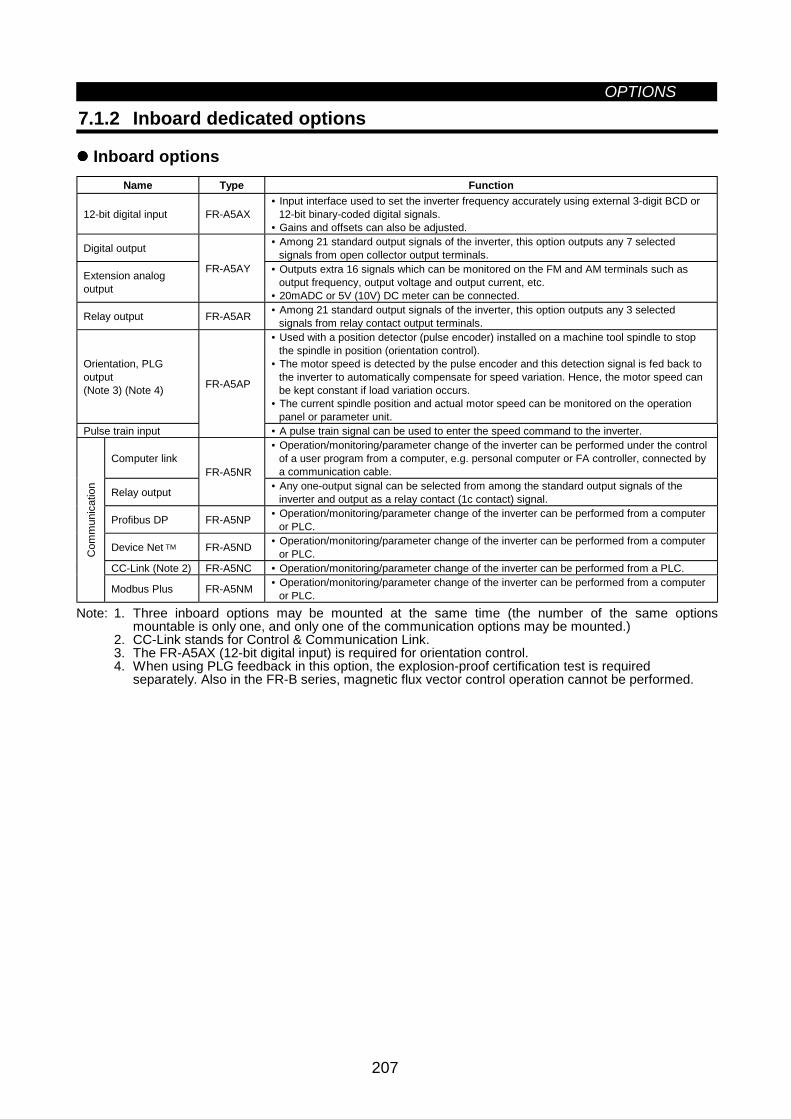
OPTIONS
207
7.1.2 Inboard dedicated options
Inboard optionsName Type Function
12-bit digital input FR-A5AX• Input interface used to set the inverter frequency accurately using external 3-digit BCD or
12-bit binary-coded digital signals.• Gains and offsets can also be adjusted.
Digital output • Among 21 standard output signals of the inverter, this option outputs any 7 selectedsignals from open collector output terminals.
Extension analogoutput
FR-A5AY • Outputs extra 16 signals which can be monitored on the FM and AM terminals such asoutput frequency, output voltage and output current, etc.
• 20mADC or 5V (10V) DC meter can be connected.
Relay output FR-A5AR • Among 21 standard output signals of the inverter, this option outputs any 3 selectedsignals from relay contact output terminals.
Orientation, PLGoutput(Note 3) (Note 4)
• Used with a position detector (pulse encoder) installed on a machine tool spindle to stopthe spindle in position (orientation control).
• The motor speed is detected by the pulse encoder and this detection signal is fed back tothe inverter to automatically compensate for speed variation. Hence, the motor speed canbe kept constant if load variation occurs.
• The current spindle position and actual motor speed can be monitored on the operationpanel or parameter unit.
Pulse train input
FR-A5AP
• A pulse train signal can be used to enter the speed command to the inverter.
Computer link• Operation/monitoring/parameter change of the inverter can be performed under the control
of a user program from a computer, e.g. personal computer or FA controller, connected bya communication cable.
Relay output
FR-A5NR• Any one-output signal can be selected from among the standard output signals of the
inverter and output as a relay contact (1c contact) signal.
Profibus DP FR-A5NP • Operation/monitoring/parameter change of the inverter can be performed from a computeror PLC.
Device Net TM FR-A5ND • Operation/monitoring/parameter change of the inverter can be performed from a computeror PLC.
CC-Link (Note 2) FR-A5NC • Operation/monitoring/parameter change of the inverter can be performed from a PLC.
Com
mun
icat
ion
Modbus Plus FR-A5NM • Operation/monitoring/parameter change of the inverter can be performed from a computeror PLC.
Note: 1. Three inboard options may be mounted at the same time (the number of the same optionsmountable is only one, and only one of the communication options may be mounted.)
2. CC-Link stands for Control & Communication Link.3. The FR-A5AX (12-bit digital input) is required for orientation control.4. When using PLG feedback in this option, the explosion-proof certification test is required
separately. Also in the FR-B series, magnetic flux vector control operation cannot be performed.
8
APPENDICES
This chapter provides the "appendices" for use of thisproduct.Always read the instructions before using the equipment.
Appendix 1 Data Code List ..................................................208
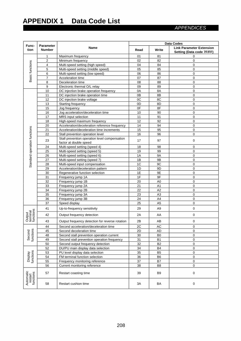
APPENDIX 1 Data Code ListAPPENDICES
208
APPENDICESAppendix 1 Data Code List
APPENDIXData CodesFunc-
tionParameterNumber Name Read Write Link Parameter Extension
Setting (Data code 7F/FF)1 Maximum frequency 01 81 02 Minimum frequency 02 82 04 Multi-speed setting (high speed) 04 84 05 Multi-speed setting (middle speed) 05 85 06 Multi-speed setting (low speed) 06 86 07 Acceleration time 07 87 08 Deceleration time 08 88 0Ba
sic
func
tions
9 Electronic thermal O/L relay 09 89 010 DC injection brake operation frequency 0A 8A 011 DC injection brake operation time 0B 8B 012 DC injection brake voltage 0C 8C 013 Starting frequency 0D 8D 015 Jog frequency 0F 8F 016 Jog acceleration/deceleration time 10 90 017 MRS input selection 11 91 018 High-speed maximum frequency 12 92 020 Acceleration/deceleration reference frequency 14 94 021 Acceleration/deceleration time increments 15 95 022 Stall prevention operation level 16 96 0
23 Stall prevention operation level compensationfactor at double speed 17 97 0
24 Multi-speed setting (speed 4) 18 98 025 Multi-speed setting (speed 5) 19 99 026 Multi-speed setting (speed 6) 1A 9A 027 Multi-speed setting (speed 7) 1B 9B 028 Multi-speed input compensation 1C 9C 029 Acceleration/deceleration pattern 1D 9D 030 Regenerative function selection 1E 9E 031 Frequency jump 1A 1F 9F 032 Frequency jump 1B 20 A0 033 Frequency jump 2A 21 A1 034 Frequency jump 2B 22 A2 035 Frequency jump 3A 23 A3 036 Frequency jump 3B 24 A4 0
Stan
dard
ope
ratio
n fu
nctio
ns
37 Speed display 25 A5 041 Up-to-frequency sensitivity 29 A9 0
42 Output frequency detection 2A AA 0
Out
put
term
inal
func
tions
43 Output frequency detection for reverse rotation 2B AB 044 Second acceleration/deceleration time 2C AC 045 Second deceleration time 2D AD 048 Second stall prevention operation current 30 B0 049 Second stall prevention operation frequency 31 B1 0Se
cond
func
tions
50 Second output frequency detection 32 B2 052 DU/PU main display data selection 34 B4 053 PU level display data selection 35 B5 054 FM terminal function selection 36 B6 055 Frequency monitoring reference 37 B7 0D
ispl
ayfu
nctio
ns
56 Current monitoring reference 38 B8 0
57 Restart coasting time 39 B9 0
Auto
mat
icre
star
tfu
nctio
ns
58 Restart cushion time 3A BA 0
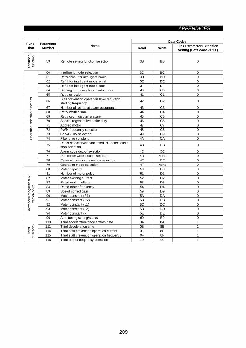
APPENDICES
209
Data CodesFunc-tion
ParameterNumber Name Read Write Link Parameter Extension
Setting (Data code 7F/FF)
Addi
tiona
lfu
nctio
n
59 Remote setting function selection 3B BB 0
60 Intelligent mode selection 3C BC 061 Reference I for intelligent mode 3D BD 062 Ref. I for intelligent mode accel 3E BE 063 Ref. I for intelligent mode decel 3F BF 064 Starting frequency for elevator mode 40 C0 065 Retry selection 41 C1 0
66 Stall prevention operation level reductionstarting frequency 42 C2 0
67 Number of retries at alarm occurrence 43 C3 068 Retry waiting time 44 C4 069 Retry count display erasure 45 C5 070 Special regenerative brake duty 46 C6 071 Applied motor 47 C7 072 PWM frequency selection 48 C8 073 0-5V/0-10V selection 49 C9 074 Filter time constant 4A CA 0
75 Reset selection/disconnected PU detection/PUstop selection 4B CB 0
76 Alarm code output selection 4C CC 077 Parameter write disable selection 4D None 078 Reverse rotation prevention selection 4E CE 0
Ope
ratio
n se
lect
ion
func
tions
79 Operation mode selection 4F None 080 Motor capacity 50 D0 081 Number of motor poles 51 D1 082 Motor exciting current 52 D2 083 Rated motor voltage 53 D3 084 Rated motor frequency 54 D4 089 Speed control gain 59 D9 090 Motor constant (R1) 5A DA 091 Motor constant (R2) 5B DB 092 Motor constant (L1) 5C DC 093 Motor constant (L2) 5D DD 094 Motor constant (X) 5E DE 0
Adva
nced
mag
netic
flux
vect
orco
ntro
l
96 Auto tuning setting/status 60 E0 0110 Third acceleration/deceleration time 0A 8A 1111 Third deceleration time 0B 8B 1114 Third stall prevention operation current 0E 8E 1115 Third stall prevention operation frequency 0F 8F 1Th
irdfu
nctio
ns
116 Third output frequency detection 10 90 1
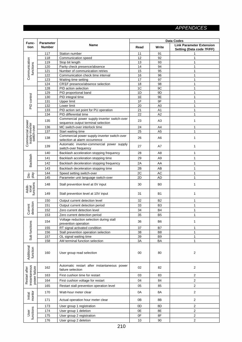
APPENDICES
210
Data CodesFunc-tion
ParameterNumber Name Read Write Link Parameter Extension
Setting (Data code 7F/FF)117 Station number 11 91 1118 Communication speed 12 92 1119 Stop bit length 13 93 1120 Parity check presence/absence 14 94 1121 Number of communication retries 15 95 1122 Communication check time interval 16 96 1123 Waiting time setting 17 97 1C
omm
unic
atio
nfu
nctio
ns
124 CR⋅LF presence/absence selection 18 98 1128 PID action selection 1C 9C 1129 PID proportional band 1D 9D 1130 PID integral time 1E 9E 1131 Upper limit 1F 9F 1132 Lower limit 20 A0 1133 PID action set point for PU operation 21 A1 1PI
D c
ontro
l
134 PID differential time 22 A2 1
135 Commercial power supply-inverter switch-oversequence output terminal selection 23 A3 1
136 MC switch-over interlock time 24 A4 1137 Start waiting time 25 A5 1
138 Commercial power supply-inverter switch-overselection at alarm occurrence 26 A6 1
Com
mer
cial
pow
ersu
pply
-inve
rter
switc
h-ov
er
139 Automatic inverter-commercial power supplyswitch-over frequency 27 A7 1
140 Backlash acceleration stopping frequency 28 A8 1141 Backlash acceleration stopping time 29 A9 1142 Backlash deceleration stopping frequency 2A AA 1
Back
lash
143 Backlash deceleration stopping time 2B AB 1144 Speed setting switch-over 2C AC 1
Dis
-pl
ay
145 Parameter unit language switch-over 2D AD 1
148 Stall prevention level at 0V input 30 B0 1
Addi
t-io
nal
func
tions
149 Stall prevention level at 10V input 31 B1 1
150 Output current detection level 32 B2 1151 Output current detection period 33 B3 1152 Zero current detection level 34 B4 1
Cur
rent
dete
ctio
n
153 Zero current detection period 35 B5 1
154 Voltage reduction selection during stallprevention operation 36 B6 1
155 RT signal activated condition 37 B7 1156 Stall prevention operation selection 38 B8 1157 OL signal waiting time 39 B9 1
Sub
func
tions
158 AM terminal function selection 3A BA 1
Addi
tiona
lfu
nctio
n
160 User group read selection 00 80 2
162 Automatic restart after instantaneous powerfailure selection 02 82 2
163 First cushion time for restart 03 83 2164 First cushion voltage for restart 04 84 2
Res
tart
afte
rin
stan
tane
ous
pow
er fa
ilure
165 Restart stall prevention operation level 05 85 2
170 Watt-hour meter clear 0A 8A 2
Initi
alm
onito
r
171 Actual operation hour meter clear 0B 8B 2
173 User group 1 registration 0D 8D 2174 User group 1 deletion 0E 8E 2175 User group 2 registration 0F 8F 2U
ser
func
tions
176 User group 2 deletion 10 90 2
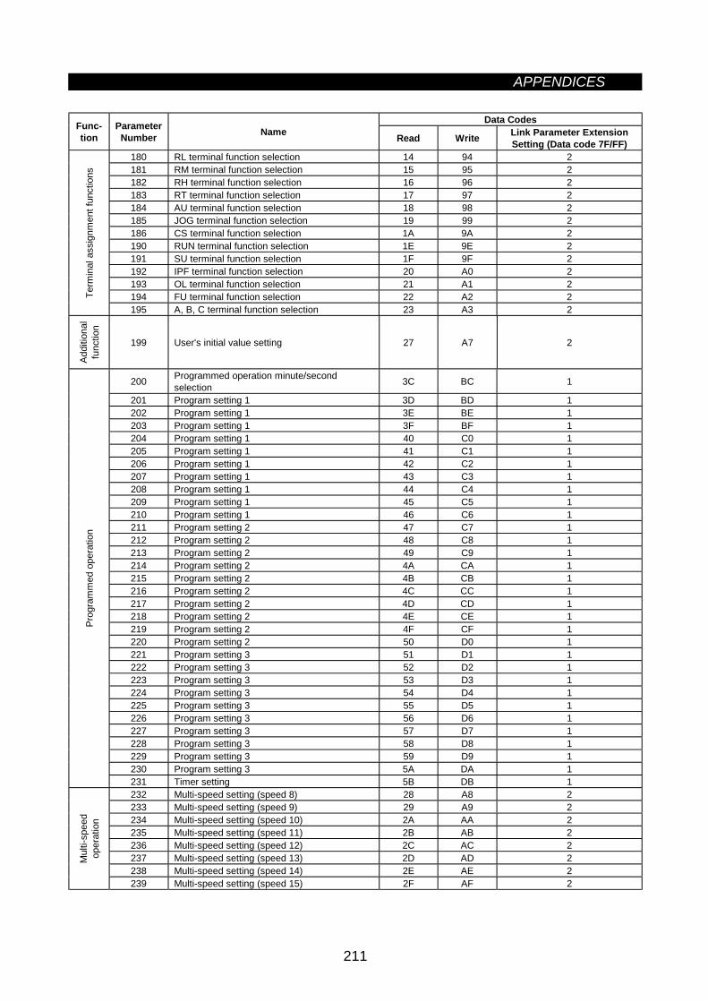
APPENDICES
211
Data CodesFunc-tion
ParameterNumber Name Read Write Link Parameter Extension
Setting (Data code 7F/FF)180 RL terminal function selection 14 94 2181 RM terminal function selection 15 95 2182 RH terminal function selection 16 96 2183 RT terminal function selection 17 97 2184 AU terminal function selection 18 98 2185 JOG terminal function selection 19 99 2186 CS terminal function selection 1A 9A 2190 RUN terminal function selection 1E 9E 2191 SU terminal function selection 1F 9F 2192 IPF terminal function selection 20 A0 2193 OL terminal function selection 21 A1 2194 FU terminal function selection 22 A2 2Te
rmin
al a
ssig
nmen
t fun
ctio
ns
195 A, B, C terminal function selection 23 A3 2
Addi
tiona
lfu
nctio
n
199 User's initial value setting 27 A7 2
200 Programmed operation minute/secondselection 3C BC 1
201 Program setting 1 3D BD 1202 Program setting 1 3E BE 1203 Program setting 1 3F BF 1204 Program setting 1 40 C0 1205 Program setting 1 41 C1 1206 Program setting 1 42 C2 1207 Program setting 1 43 C3 1208 Program setting 1 44 C4 1209 Program setting 1 45 C5 1210 Program setting 1 46 C6 1211 Program setting 2 47 C7 1212 Program setting 2 48 C8 1213 Program setting 2 49 C9 1214 Program setting 2 4A CA 1215 Program setting 2 4B CB 1216 Program setting 2 4C CC 1217 Program setting 2 4D CD 1218 Program setting 2 4E CE 1219 Program setting 2 4F CF 1220 Program setting 2 50 D0 1221 Program setting 3 51 D1 1222 Program setting 3 52 D2 1223 Program setting 3 53 D3 1224 Program setting 3 54 D4 1225 Program setting 3 55 D5 1226 Program setting 3 56 D6 1227 Program setting 3 57 D7 1228 Program setting 3 58 D8 1229 Program setting 3 59 D9 1230 Program setting 3 5A DA 1
Prog
ram
med
ope
ratio
n
231 Timer setting 5B DB 1232 Multi-speed setting (speed 8) 28 A8 2233 Multi-speed setting (speed 9) 29 A9 2234 Multi-speed setting (speed 10) 2A AA 2235 Multi-speed setting (speed 11) 2B AB 2236 Multi-speed setting (speed 12) 2C AC 2237 Multi-speed setting (speed 13) 2D AD 2238 Multi-speed setting (speed 14) 2E AE 2
Mul
ti-sp
eed
oper
atio
n
239 Multi-speed setting (speed 15) 2F AF 2
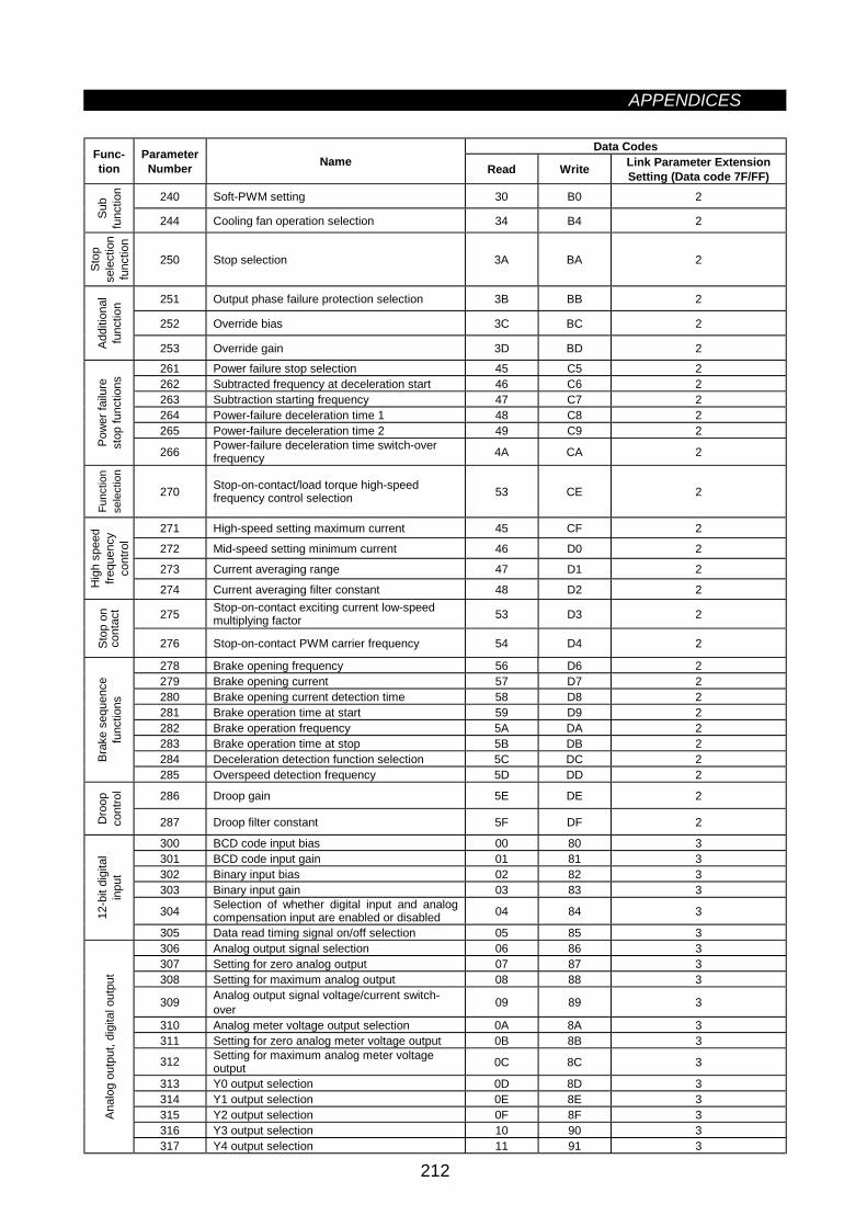
APPENDICES
212
Data CodesFunc-tion
ParameterNumber Name Read Write Link Parameter Extension
Setting (Data code 7F/FF)240 Soft-PWM setting 30 B0 2
Sub
func
tion
244 Cooling fan operation selection 34 B4 2
Stop
sele
ctio
nfu
nctio
n
250 Stop selection 3A BA 2
251 Output phase failure protection selection 3B BB 2
252 Override bias 3C BC 2
Addi
tiona
lfu
nctio
n
253 Override gain 3D BD 2
261 Power failure stop selection 45 C5 2262 Subtracted frequency at deceleration start 46 C6 2263 Subtraction starting frequency 47 C7 2264 Power-failure deceleration time 1 48 C8 2265 Power-failure deceleration time 2 49 C9 2
Pow
er fa
ilure
stop
func
tions
266 Power-failure deceleration time switch-overfrequency 4A CA 2
Func
tion
sele
ctio
n
270 Stop-on-contact/load torque high-speedfrequency control selection 53 CE 2
271 High-speed setting maximum current 45 CF 2
272 Mid-speed setting minimum current 46 D0 2
273 Current averaging range 47 D1 2
Hig
h sp
eed
frequ
ency
cont
rol
274 Current averaging filter constant 48 D2 2
275 Stop-on-contact exciting current low-speedmultiplying factor 53 D3 2
Stop
on
cont
act
276 Stop-on-contact PWM carrier frequency 54 D4 2
278 Brake opening frequency 56 D6 2279 Brake opening current 57 D7 2280 Brake opening current detection time 58 D8 2281 Brake operation time at start 59 D9 2282 Brake operation frequency 5A DA 2283 Brake operation time at stop 5B DB 2284 Deceleration detection function selection 5C DC 2Br
ake
sequ
ence
func
tions
285 Overspeed detection frequency 5D DD 2
286 Droop gain 5E DE 2
Dro
opco
ntro
l
287 Droop filter constant 5F DF 2
300 BCD code input bias 00 80 3301 BCD code input gain 01 81 3302 Binary input bias 02 82 3303 Binary input gain 03 83 3
304 Selection of whether digital input and analogcompensation input are enabled or disabled 04 84 312
-bit
digi
tal
inpu
t
305 Data read timing signal on/off selection 05 85 3306 Analog output signal selection 06 86 3307 Setting for zero analog output 07 87 3308 Setting for maximum analog output 08 88 3
309 Analog output signal voltage/current switch-over 09 89 3
310 Analog meter voltage output selection 0A 8A 3311 Setting for zero analog meter voltage output 0B 8B 3
312 Setting for maximum analog meter voltageoutput 0C 8C 3
313 Y0 output selection 0D 8D 3314 Y1 output selection 0E 8E 3315 Y2 output selection 0F 8F 3316 Y3 output selection 10 90 3
Anal
og o
utpu
t, di
gita
l out
put
317 Y4 output selection 11 91 3
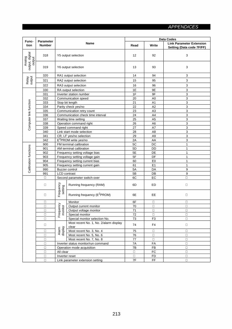
APPENDICES
213
Data CodesFunc-tion
ParameterNumber Name Read Write Link Parameter Extension
Setting (Data code 7F/FF)
318 Y5 output selection 12 92 3
Anal
ogou
tput
, dig
ital
outp
ut
319 Y6 output selection 13 93 3
320 RA1 output selection 14 94 3321 RA2 output selection 15 95 3
Rel
ayou
tput
322 RA3 output selection 16 96 3330 RA output selection 1E 9E 3331 Inverter station number 1F 9F 3332 Communication speed 20 A0 3333 Stop bit length 21 A1 3334 Parity check yes/no 22 A2 3335 Communication retry count 23 A3 3336 Communication check time interval 24 A4 3337 Waiting time setting 25 A5 3338 Operation command right 26 A6 3339 Speed command right 27 A7 3340 Link start mode selection 28 A8 3341 CR, LF yes/no selection 29 A9 3
Com
pute
r lin
k fu
nctio
n
342 E2PROM write yes/no 2A AA 3900 FM terminal calibration 5C DC 1901 AM terminal calibration 5D DD 1902 Frequency setting voltage bias 5E DE 1903 Frequency setting voltage gain 5F DF 1904 Frequency setting current bias 60 E0 1905 Frequency setting current gain 61 E1 1990 Buzzer control 5A DA 9
Cal
ibra
tion
func
tions
991 LCD contrast 5B DB 9 Second parameter switch-over 6C EC
Running frequency (RAM) 6D ED
Freq
uenc
yse
tting
Running frequency (E2PROM) 6E EE
Monitor 6F Output current monitor 70 Output voltage monitor 71 Special monitor 72
Freq
uenc
ym
onito
r
Special monitor selection No. 73 F3
Most recent No. 1, No. 2/alarm displayclear 74 F4
Most recent No. 3, No. 4 75 Most recent No. 5, No. 6 76
Alar
mdi
spla
y
Most recent No. 7, No. 8 77 Inverter status monitor/run command 7A FA Operation mode acquisition 7B FB All clear FC Inverter reset FD Link parameter extension setting 7F FF

REVISIONS* The manual number is given on the bottom left of the back cover.
Print Data *Manual Number Revision
Mar., 2000 IB(NA)-0600011-A First editionNov., 2003 IB(NA)-0600011-B Modification
Error correction