instruction manual vcc-4115p bedienungsanleitung …
TRANSCRIPT
INSTRUCTION MANUALBEDIENUNGSANLEITUNGMANUEL D’INSTRUCTIONS
VCC-4115P
COLOUR CCD cameraCCD-FarbkameraCaméra CCD COULEUR
CCD
About this manualBefore installing and using the camera, please read this manual carefully. Be sure to keep it handy for later reference.
Über diese BedienungsanleitungLesen Sie bitte vor der Montage und dem Inbetriebnehmen der Kamera zuerst diese Bedienungsanleitung sorgfältig durch und bewahren Sie sie zum späteren Nachschlagen auf.
A propos de ce manuelAvant d’installer et d’utiliser la caméra, veuillez lire ce manuel attentivement. Gardez-le à portée de main pour toute référence ultérieure.
COVER1.fm 1 ページ 2002年9月6日 金曜日 午後6時34分
English 1
Depending on the conditions of use, installation and environment, please be sure to make the appropriate settings and adjustments. If you need help with installation and/or settings, please consult your dealer.
CONTENTSPRECAUTIONS .................................................. 2PARTS NAMES .................................................. 3MOUNTING THE LENS...................................... 5CONNECTIONS.................................................. 7SETTINGS .......................................................... 8TROUBLESHOOTING...................................... 13SPECIFICATIONS ............................................ 14
FEATURES• Built-in interline transfer method 1/4" CCD, approx.
320,000 picture elements
• Equipped with a DSP (Digital Signal Processor) function
• Horizontal resolution, more than 350 TV lines
• High sensitivity, minimum required illumination is 0.9 lux (F1.2)
• Two types of backlight compensation functions (multi-spot photometry and center focus photometry)
• Low smear, anti-blooming, low lag, no burning and no geometric distortion using the CCD solid state image device.
• 100% solid state components giving excellent immunity to shock and vibration
• Not subject to interference from magnetic or electrostatic fields
• Power supply: 24 V AC and 12 V DC operation
• Use a DC type auto-iris lens.
vcc4115p(gb).fm 1 ページ 2002年9月5日 木曜日 午後3時59分
EN
GL
ISH
2 English
PRECAUTIONS���� In case of problemDo not use the camera if smoke or a strange odour comes from the unit, or if it seems not to function correctly. Disconnect the power cord immediately, and consult your dealer (or a Sanyo Authorized Service Centre).
���� Do not open or modifyDo not open the cabinet, as it may be dangerous and cause damage to the unit. For internal settings and repairs, consult your dealer (or a Sanyo Authorized Service Centre).
���� Do not put objects inside the unitMake sure that no metal objects or flammable substance get inside the camera. If used with a foreign object inside, it could cause a fire, short-circuits or damages.If water or a liquid gets inside the camera, disconnect the power cord immediately, and consult your dealer (or a Sanyo Authorized Service Centre). Be careful to protect the camera from rain, sea water, etc.
���� Be careful when handling the unitTo prevent damages, do not drop the camera or subject it to strong shock or vibration.
���� Install away from electric or magnetic fieldsIf installed close to a TV, radio transmitter, magnet, electric motor, transformer, audio speakers the magnetic field they generate will distort the image.
���� Protect from humidity and dustTo prevent damages to the camera, do not install it where there is greasy smoke or steam, where the dampness may get too high, or where there is a lot of dust.
���� Protect from high temperaturesDo not install close to stoves, or other heat generating devices, such as spotlights, etc., or where it could be subject to direct sunlight, as that could cause deformation, discoloration or other damages.
Be careful when installing close to the ceiling, in a kitchen or boiler room, as the temperature may raise to high levels.
Install where the temperature range will stay between –10°C and 50°C. (no condensation)
���� Cleaning• Dirt can be removed from the cabinet by wiping it with a soft
cloth. To remove stains, wipe with a soft cloth moistened with a soft detergent solution and wrung dry, then wipe dry with dry soft cloth.
• Do not use benzine, thinner or other chemical product on the cabinet, as that may cause deformation and paint peeling. Before using a chemical cloth, make sure to read all accompanying instructions. Make sure that no plastic or rubber material comes in contact with the cabinet for a long period of time, as that may cause damage or paint peeling.
vcc4115p(gb).fm 2 ページ 2002年9月5日 木曜日 午後3時59分
English 3
PARTS NAMES
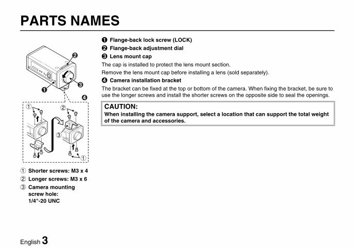
1 Shorter screws: M3 x 4
2 Longer screws: M3 x 6
3 Camera mounting screw hole: 1/4"-20 UNC
1
2
3
4
1 Flange-back lock screw (LOCK)
2 Flange-back adjustment dial
3 Lens mount cap
The cap is installed to protect the lens mount section.
Remove the lens mount cap before installing a lens (sold separately).
4 Camera installation bracket
The bracket can be fixed at the top or bottom of the camera. When fixing the bracket, be sure to use the longer screws and install the shorter screws on the opposite side to seal the openings.
CAUTION:When installing the camera support, select a location that can support the total weight of the camera and accessories.
vcc4115p(gb).fm 3 ページ 2002年9月5日 木曜日 午後3時59分
4 English
PARTS NAMES
9
8
67
5
F
G
H
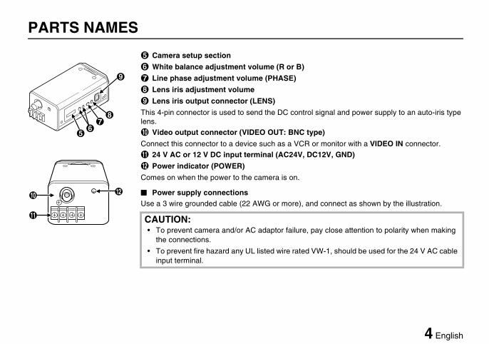
5 Camera setup section
6 White balance adjustment volume (R or B)
7 Line phase adjustment volume (PHASE)
8 Lens iris adjustment volume
9 Lens iris output connector (LENS)
This 4-pin connector is used to send the DC control signal and power supply to an auto-iris type lens.
F Video output connector (VIDEO OUT: BNC type)
Connect this connector to a device such as a VCR or monitor with a VIDEO IN connector.
G 24 V AC or 12 V DC input terminal (AC24V, DC12V, GND)
H Power indicator (POWER)
Comes on when the power to the camera is on.
���� Power supply connectionsUse a 3 wire grounded cable (22 AWG or more), and connect as shown by the illustration.
CAUTION:• To prevent camera and/or AC adaptor failure, pay close attention to polarity when making
the connections.
• To prevent fire hazard any UL listed wire rated VW-1, should be used for the 24 V AC cable input terminal.
vcc4115p(gb).fm 4 ページ 2002年9月5日 木曜日 午後3時59分
English 5
MOUNTING THE LENS
1
2
C mount type lens
CS mount type lens
23
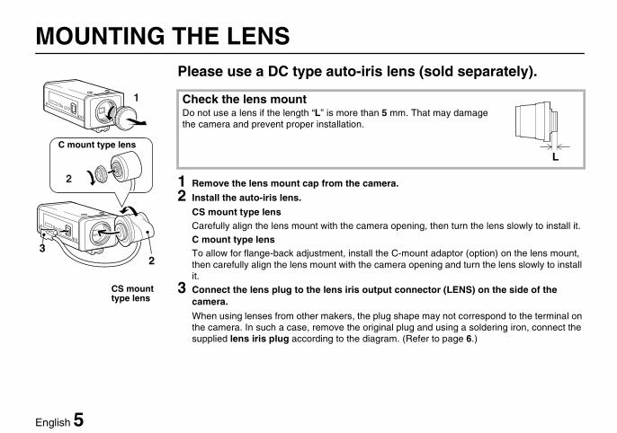
Please use a DC type auto-iris lens (sold separately).
1 Remove the lens mount cap from the camera.
2 Install the auto-iris lens.
CS mount type lensCarefully align the lens mount with the camera opening, then turn the lens slowly to install it.
C mount type lensTo allow for flange-back adjustment, install the C-mount adaptor (option) on the lens mount, then carefully align the lens mount with the camera opening and turn the lens slowly to install it.
3 Connect the lens plug to the lens iris output connector (LENS) on the side of the camera.
When using lenses from other makers, the plug shape may not correspond to the terminal on the camera. In such a case, remove the original plug and using a soldering iron, connect the supplied lens iris plug according to the diagram. (Refer to page 6.)
Check the lens mountDo not use a lens if the length “L” is more than 5 mm. That may damage the camera and prevent proper installation.
L
vcc4115p(gb).fm 5 ページ 2002年9月5日 木曜日 午後3時59分
6 English
MOUNTING THE LENS
4 3
12
1
3
2
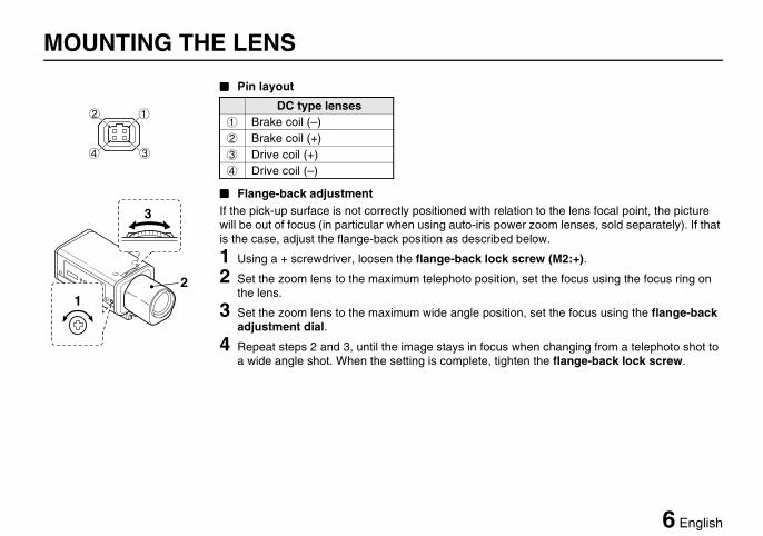
���� Pin layout
���� Flange-back adjustmentIf the pick-up surface is not correctly positioned with relation to the lens focal point, the picture will be out of focus (in particular when using auto-iris power zoom lenses, sold separately). If that is the case, adjust the flange-back position as described below.
1 Using a + screwdriver, loosen the flange-back lock screw (M2:+).
2 Set the zoom lens to the maximum telephoto position, set the focus using the focus ring on the lens.
3 Set the zoom lens to the maximum wide angle position, set the focus using the flange-back adjustment dial.
4 Repeat steps 2 and 3, until the image stays in focus when changing from a telephoto shot to a wide angle shot. When the setting is complete, tighten the flange-back lock screw.
DC type lenses1 Brake coil (–)2 Brake coil (+)3 Drive coil (+)4 Drive coil (–)
vcc4115p(gb).fm 6 ページ 2002年9月6日 金曜日 午後5時36分
English 7
CONNECTIONS
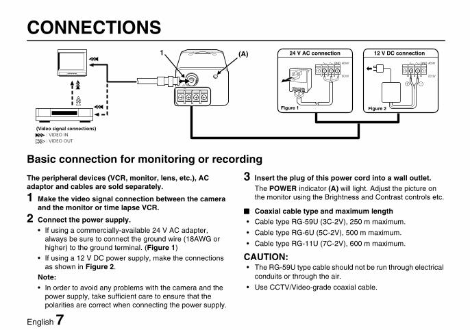
Basic connection for monitoring or recording
The peripheral devices (VCR, monitor, lens, etc.), AC adaptor and cables are sold separately.
1 Make the video signal connection between the camera and the monitor or time lapse VCR.
2 Connect the power supply.• If using a commercially-available 24 V AC adapter,
always be sure to connect the ground wire (18AWG or higher) to the ground terminal. (Figure 1)
• If using a 12 V DC power supply, make the connections as shown in Figure 2.
Note:• In order to avoid any problems with the camera and the
power supply, take sufficient care to ensure that the polarities are correct when connecting the power supply.
3 Insert the plug of this power cord into a wall outlet.The POWER indicator (A) will light. Adjust the picture on the monitor using the Brightness and Contrast controls etc.
���� Coaxial cable type and maximum length• Cable type RG-59U (3C-2V), 250 m maximum.
• Cable type RG-6U (5C-2V), 500 m maximum.
• Cable type RG-11U (7C-2V), 600 m maximum.
CAUTION:• The RG-59U type cable should not be run through electrical
conduits or through the air.
• Use CCTV/Video-grade coaxial cable.
GND AC24V
DC12V
GND AC24V
DC12V
(Video signal connections) : VIDEO IN : VIDEO OUT
(A)1 24 V AC connection
Figure 1 Figure 2
12 V DC connection
vcc4115p(gb).fm 7 ページ 2002年9月5日 木曜日 午後4時0分
8 English
SETTINGS
12 5634
7
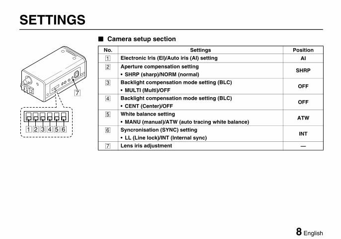
���� Camera setup section
No. Settings Position
1 Electronic Iris (EI)/Auto iris (AI) setting AI
2 Aperture compensation settingSHRP
• SHRP (sharp)/NORM (normal)
3 Backlight compensation mode setting (BLC)OFF
• MULTI (Multi)/OFF
4 Backlight compensation mode setting (BLC)OFF
• CENT (Center)/OFF
5 White balance settingATW
• MANU (manual)/ATW (auto tracing white balance)
6 Syncronisation (SYNC) settingINT
• LL (Line lock)/INT (Internal sync)
7 Lens iris adjustment —
vcc4115p(gb).fm 8 ページ 2002年9月9日 月曜日 午前11時53分
English 9
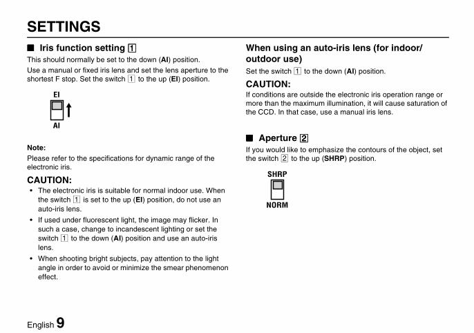
SETTINGS���� Iris function setting 1111This should normally be set to the down (AI) position.
Use a manual or fixed iris lens and set the lens aperture to the shortest F stop. Set the switch 1 to the up (EI) position.
Note:Please refer to the specifications for dynamic range of the electronic iris.
CAUTION:• The electronic iris is suitable for normal indoor use. When
the switch 1 is set to the up (EI) position, do not use an auto-iris lens.
• If used under fluorescent light, the image may flicker. In such a case, change to incandescent lighting or set the switch 1 to the down (AI) position and use an auto-iris lens.
• When shooting bright subjects, pay attention to the light angle in order to avoid or minimize the smear phenomenon effect.
When using an auto-iris lens (for indoor/outdoor use)Set the switch 1 to the down (AI) position.
CAUTION:If conditions are outside the electronic iris operation range or more than the maximum illumination, it will cause saturation of the CCD. In that case, use a manual iris lens.
���� Aperture 2222If you would like to emphasize the contours of the object, set the switch 2 to the up (SHRP) position.
AI
EI
NORM
SHRP
vcc4115p(gb).fm 9 ページ 2002年9月9日 月曜日 午前11時53分

10 English
SETTINGS���� Backlight compensation setting 3 43 43 43 4
This camera has two different backlight correction functions: multi-spot photometry (MULTI) and center focus photometry (CENT). The normal setting (switch 3 and 4) is the down position, but you can change the switch 3 or 4 setting in accordance with the backlight conditions.
Note:• When using the backlight compensation function, set the
switch 3 or 4 to the up position. When not using the function, set the switch 3 and 4 to the down (OFF) position.
• When MULTI mode is set, scenes with no backlighting may appear extremely dark and the object may appear over-exposed. If this happens, move the switch 4 to the up (CENT) position.
(MULTI mode: 64 sections)
(CENT mode)• MULTI mode: Use this position when applying backlight
compensation to the whole of the screen.• CENT mode: Use this position when applying backlight
compensation to only the central portion of the screen.
MULTI CENT
3 4
vcc4115p(gb).fm 10 ページ 2002年9月5日 木曜日 午後5時58分
English 11
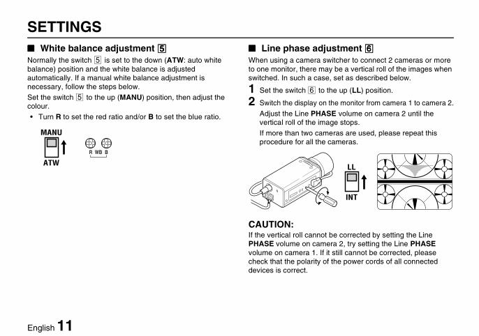
SETTINGS���� White balance adjustment 5555Normally the switch 5 is set to the down (ATW: auto white balance) position and the white balance is adjusted automatically. If a manual white balance adjustment is necessary, follow the steps below.
Set the switch 5 to the up (MANU) position, then adjust the colour.
• Turn R to set the red ratio and/or B to set the blue ratio.
���� Line phase adjustment 6666When using a camera switcher to connect 2 cameras or more to one monitor, there may be a vertical roll of the images when switched. In such a case, set as described below.
1 Set the switch 6 to the up (LL) position.
2 Switch the display on the monitor from camera 1 to camera 2.
Adjust the Line PHASE volume on camera 2 until the vertical roll of the image stops.
If more than two cameras are used, please repeat this procedure for all the cameras.
CAUTION:If the vertical roll cannot be corrected by setting the Line PHASE volume on camera 2, try setting the Line PHASE volume on camera 1. If it still cannot be corrected, please check that the polarity of the power cords of all connected devices is correct.
ATW
MANU
R BWB
INT
LL
vcc4115p(gb).fm 11 ページ 2002年9月5日 木曜日 午後4時0分
12 English
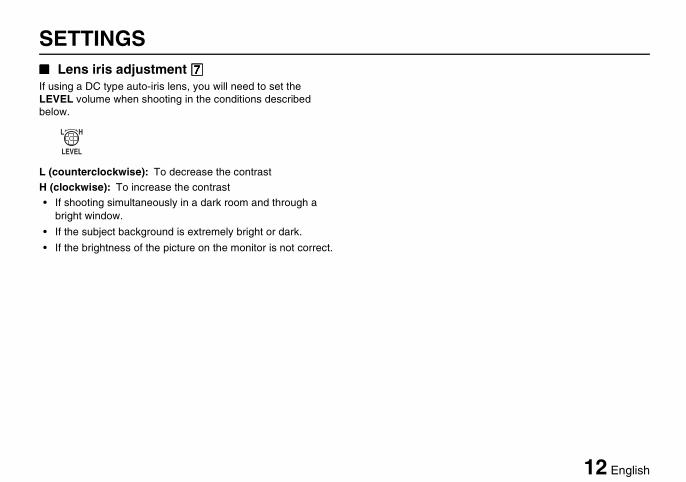
SETTINGS���� Lens iris adjustment 7777If using a DC type auto-iris lens, you will need to set the LEVEL volume when shooting in the conditions described below.
L (counterclockwise): To decrease the contrast
H (clockwise): To increase the contrast
• If shooting simultaneously in a dark room and through a bright window.
• If the subject background is extremely bright or dark.
• If the brightness of the picture on the monitor is not correct.
LEVEL
L H
vcc4115p(gb).fm 12 ページ 2002年9月5日 木曜日 午後4時0分
English 13
TROUBLESHOOTINGBefore taking the camera for repairs, please check below to make sure that the camera is used correctly. If it still does not perform correctly, please consult your dealer or a Sanyo Authorized Service Centre.
���� No picture on the monitor screen• Is the power turned on to all connected devices? Is the voltage correct?
• Are all the signal connecting cables correctly connected?
• Is the lighting sufficient?
• Has the lens cap been removed?
• Is the iris control correctly set?
���� The picture is not clear• Is the monitor correctly adjusted?
• Is the flange-back position correctly set?
• Is the lens focus correctly adjusted?
• Are the lens surfaces clean?
If there is dust or finger prints on the lens, the image quality will deteriorate. To clean the lens use a soft cloth or a commercially available lens cleaning set.
SERVICEThis camera is a precision instruments and if treated with care, will provide years of satisfactory performance. However, in the event of a problem, the owner is advised not to attempt to make repairs or open the cabinet. Servicing should always be referred to your dealer or Sanyo Authorized Service Centre.
vcc4115p(gb).fm 13 ページ 2002年9月5日 木曜日 午後4時0分
14 English
SPECIFICATIONS���� Camera:
SERVICEThis camera is a precision instruments and if treated with care, will provide years of satisfactory performance. However, in the event of a problem, the owner is advised not to attempt to make repairs or open the cabinet. Servicing should always be referred to your dealer or Sanyo Authorized Service Centre.
Scanning system : PAL standard(625 TV lines, 25 frames/sec.)
Interlace : PLL 2:1 interlaceImage device : 1/4 inch solid state image
device CCD Picture elements : 537 (H) x 597 (V)Effective picture elements : 500 (H) x 582 (V)Synchronizing system : Internal sync, Line lock
manually switchableResolution : 350 TV lines horizontally, 400
TV lines verticallyVideo output level : 1.0 Vp-p/75 ohms, compositeVideo S/N ratio : More than 48 dBMinimum required illumination (incandescent lighting)
: Approx. 0.9 lux with a F 1.2 lens
Backlight compensation : MULTI/OFF switching, CENT/OFF switching
Iris function : Manual EI/AI switchingElectronic iris range : 0.9 lux to 45,000 lux (F 1.2
lens)Flange-back : 12.5 mm ± 0.5 mmWhite balance : ATW/Manual switchingLens mount : CS mount
Environmental conditions : Temperature: –10°C – +50°CHumidity: less than 90% (no condensation)
Power supply : 24 V AC, 50 Hz/12 V – 15 V DCPower consumption : Approx. 2.8 W (with AI, lens)
Approx. 2.2 W (without AI, lens)Weight : Approx. 280 g (without lens)
vcc4115p(gb).fm 14 ページ 2002年9月9日 月曜日 午前11時54分
English 15
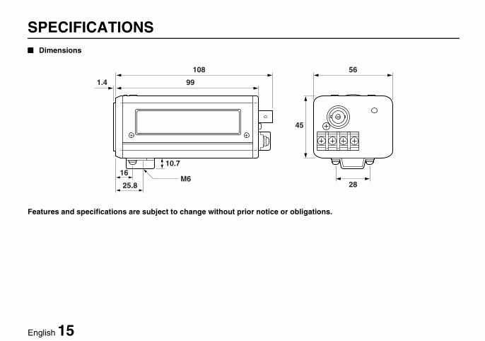
SPECIFICATIONS���� Dimensions
Features and specifications are subject to change without prior notice or obligations.
1.4
108
99
10.7
M616
25.8
45
56
28
vcc4115p(gb).fm 15 ページ 2002年9月5日 木曜日 午後4時0分