instruction set - | anna university notesstudentsfocus.com/notes/anna_university/eee/5sem/ee6502 -...
TRANSCRIPT

Instruction Set
� Instruction set of 8085 can be classified in following groups:� Data Transfer Instructions
� These instructions can perform data transfer operations between
� Registers of 8085 e.g. MOV� 8085 registers and main memory e.g. LDA, STA, MOV,
LDAX, STAX, MVI, LXI etc.� Accumulator register and I/O devices e.g. IN, OUT
� Data transfer instructions never affect the flag bits
Instruction Set Contd..
� Arithmetic Instructions� 8085 can perform only 8-bit addition, subtraction and
compare operations. These operations are always performed with accumulator as one of the operands. The status of the result can be verified by the contents of the flag register.
� Op-codes for arithmetic instructions include ADD, ADI, ADC, ACI, SUB, SUI, SBB, SBI, CMP, CPI
� Logical Instructions � 8085 can perform 8-bit basic logical operations -AND, OR,
XOR, NOT with some special operations such as rotate and shift operations
� Logical instructions also modify the flag bits. � Op-codes for logical instructions include ANA, ANI, ORA,
ORI, XRA, XRI, CMA, RAL, RLC, RAR, RRC etc.
Instruction Set Contd..
� Program Control Instructions� These instructions are used to transfer the
program control:� to jump from one memory location to any other memory
location within a program� from one program to another program called as a
subroutine� 8085 Instruction set consists of following program
control instructions:� Jump Instructions� Call & Return Instructions� Restart instructions
Instruction Set Contd..
� Program control instructions � Unconditional or Conditional
� Unconditional program control instructions perform branching operation unconditionally
� Conditional program control instructions perform branching operation with reference to the condition of flag bits.
Instruction Set Contd..
� Unconditional Program control instructions are� JMP � Call & RET� RST n (n=0-7)
� Conditional Program control instructions are� JNC, JC, JNZ, JZ, JP, JM, JPE, JPO� CNC, CC, CNZ, CZ, CP, CM, CPE, CPO� RNC, RC, RNZ, RZ, RP, RM, RPE, RPO
Instruction Set Contd..
� Machine control Instructions� These instructions include special instructions
such as � HLT – To halt the CPU� NOP – To perform no operation� SIM – To set the masking of hardware interrupts
and serial output data� RIM – To read the status of interrupt mask and
serial input data� EI – Enable Interrupt� DI – Disable Interrupt
www.studentsfocus.com

Addressing Modes
� 8085 instructions can be classified in following addressing modes� Register Addressing mode
� Instructions which have their operands in registers only e.g. MOV, ADD, SUB, ANA, ORA, XRA etc.
� Immediate Addressing mode� Instructions in which operand immediately follows the
op-code e.g. MVI, LXI, ADI, SUI, ANI, ORI etc.� Direct Addressing mode
� Instructions have their operands in memory and the 16-bit memory address is specified in the instruction e.g. LDA, STA, LHLD, SHLD etc.
Addressing Modes Contd..
� Register Indirect Addressing mode� Instructions have their operand in memory and the 16-bit
memory address is specified in a register pair e.g. LDAX, STAX, PUSH, POP etc.
� Implicit Addressing mode� These instruction have their operand implied in the op-
code itself e.g. CMA, CMC, STC etc.
Instruction size
� An instruction is assembled in the memory of a microcomputer system in binary form. The size of an instruction signifies how much memory space is required to load an instruction in the memory. 8085 instructions are of following sizes:� One-byte Instructions
e.g. MOV, ADD, ANA, SUB, ORA etc.� Two-byte instructions
e.g. MVI, ADI, ANI, ORI, XRI etc.� Three-byte instructions
e.g. LXI, LDA, STA, LHLD, SHLD etc.
www.studentsfocus.com

Instruction FormatAn instruction is a command to the microprocessor to perform a given task on a specified data. Each instruction has two parts: one is task to be performed, called the operation code (opcode), and the second is the data to be operated on, called the operand. The operand (or data) can be specified in various ways. It may include 8-bit (or 16-bit) data, an internal register, a memory location, or 8-bit (or 16-bit) address. In some instructions, the operand is implicit.Instruction word sizeThe 8085 instruction set is classified into the following three groups according to word size:1. One-word or 1-byte instructions2. Two-word or 2-byte instructions3. Three-word or 3-byte instructionsIn the 8085, "byte" and "word" are synonymous because it is an 8-bit microprocessor.However, instructions are commonly referred to in terms of bytes rather than words.One-Byte InstructionsA 1-byte instruction includes the opcode and operand in the same byte. Operand(s) are internal register and are coded into the instruction.Example: MOV A,B Two-Byte InstructionsIn a two-byte instruction, the first byte specifies the operation code and the second byte specifies the operand. Source operand is a data byte immediately following the opcode.Example: MVI A, 32H Three-Byte InstructionsIn a three-byte instruction, the first byte specifies the opcode, and the following two bytes specify the 16-bit address. Note that the second byte is the low-order address and the third byte is the high-order address.Three byte instructions - opcode + data byte + data byteExample: LXI 21H, 0520H
www.studentsfocus.com

8085 Instruction Set Page 1
8085 INSTRUCTION SET
INSTRUCTION DETAILS
DATA TRANSFER INSTRUCTIONS
Opcode Operand Description
Copy from source to destinationMOV Rd, Rs This instruction copies the contents of the source
M, Rs register into the destination register; the contents ofRd, M the source register are not altered. If one of the operands is a
memory location, its location is specified by the contents ofthe HL registers.Example: MOV B, C or MOV B, M
Move immediate 8-bitMVI Rd, data The 8-bit data is stored in the destination register or
M, data memory. If the operand is a memory location, its location isspecified by the contents of the HL registers.Example: MVI B, 57H or MVI M, 57H
Load accumulatorLDA 16-bit address The contents of a memory location, specified by a
16-bit address in the operand, are copied to the accumulator.The contents of the source are not altered.Example: LDA 2034H
Load accumulator indirectLDAX B/D Reg. pair The contents of the designated register pair point to a memory
location. This instruction copies the contents of that memorylocation into the accumulator. The contents of either theregister pair or the memory location are not altered.Example: LDAX B
Load register pair immediateLXI Reg. pair, 16-bit data The instruction loads 16-bit data in the register pair
designated in the operand.Example: LXI H, 2034H or LXI H, XYZ
Load H and L registers directLHLD 16-bit address The instruction copies the contents of the memory location
pointed out by the 16-bit address into register L and copiesthe contents of the next memory location into register H. Thecontents of source memory locations are not altered.Example: LHLD 2040H
www.studentsfocus.com

8085 Instruction Set Page 2
Store accumulator directSTA 16-bit address The contents of the accumulator are copied into the memory
location specified by the operand. This is a 3-byte instruction,the second byte specifies the low-order address and the thirdbyte specifies the high-order address.Example: STA 4350H
Store accumulator indirectSTAX Reg. pair The contents of the accumulator are copied into the memory
location specified by the contents of the operand (registerpair). The contents of the accumulator are not altered.Example: STAX B
Store H and L registers directSHLD 16-bit address The contents of register L are stored into the memory location
specified by the 16-bit address in the operand and the contentsof H register are stored into the next memory location byincrementing the operand. The contents of registers HL arenot altered. This is a 3-byte instruction, the second bytespecifies the low-order address and the third byte specifies thehigh-order address.Example: SHLD 2470H
Exchange H and L with D and EXCHG none The contents of register H are exchanged with the contents of
register D, and the contents of register L are exchanged withthe contents of register E.Example: XCHG
Copy H and L registers to the stack pointerSPHL none The instruction loads the contents of the H and L registers into
the stack pointer register, the contents of the H registerprovide the high-order address and the contents of the Lregister provide the low-order address. The contents of the Hand L registers are not altered.Example: SPHL
Exchange H and L with top of stackXTHL none The contents of the L register are exchanged with the stack
location pointed out by the contents of the stack pointerregister. The contents of the H register are exchanged withthe next stack location (SP+1); however, the contents of thestack pointer register are not altered.Example: XTHL
www.studentsfocus.com

8085 Instruction Set Page 3
Push register pair onto stackPUSH Reg. pair The contents of the register pair designated in the operand are
copied onto the stack in the following sequence. The stackpointer register is decremented and the contents of the high-order register (B, D, H, A) are copied into that location. Thestack pointer register is decremented again and the contents ofthe low-order register (C, E, L, flags) are copied to thatlocation.Example: PUSH B or PUSH A
Pop off stack to register pairPOP Reg. pair The contents of the memory location pointed out by the stack
pointer register are copied to the low-order register (C, E, L,status flags) of the operand. The stack pointer is incrementedby 1 and the contents of that memory location are copied tothe high-order register (B, D, H, A) of the operand. The stackpointer register is again incremented by 1.Example: POP H or POP A
Output data from accumulator to a port with 8-bit addressOUT 8-bit port address The contents of the accumulator are copied into the I/O port
specified by the operand.Example: OUT F8H
Input data to accumulator from a port with 8-bit addressIN 8-bit port address The contents of the input port designated in the operand are
read and loaded into the accumulator.Example: IN 8CH
www.studentsfocus.com

8085 Instruction Set Page 4
ARITHMETIC INSTRUCTIONS
Opcode Operand Description
Add register or memory to accumulatorADD R The contents of the operand (register or memory) are
M added to the contents of the accumulator and the result isstored in the accumulator. If the operand is a memorylocation, its location is specified by the contents of the HLregisters. All flags are modified to reflect the result of theaddition.Example: ADD B or ADD M
Add register to accumulator with carryADC R The contents of the operand (register or memory) and
M the Carry flag are added to the contents of the accumulatorand the result is stored in the accumulator. If the operand is amemory location, its location is specified by the contents ofthe HL registers. All flags are modified to reflect the result ofthe addition.Example: ADC B or ADC M
Add immediate to accumulatorADI 8-bit data The 8-bit data (operand) is added to the contents of the
accumulator and the result is stored in the accumulator. Allflags are modified to reflect the result of the addition.Example: ADI 45H
Add immediate to accumulator with carryACI 8-bit data The 8-bit data (operand) and the Carry flag are added to the
contents of the accumulator and the result is stored in theaccumulator. All flags are modified to reflect the result of theaddition.Example: ACI 45H
Add register pair to H and L registersDAD Reg. pair The 16-bit contents of the specified register pair are added to
the contents of the HL register and the sum is stored in theHL register. The contents of the source register pair are notaltered. If the result is larger than 16 bits, the CY flag is set.No other flags are affected.Example: DAD H
www.studentsfocus.com

8085 Instruction Set Page 5
Subtract register or memory from accumulatorSUB R The contents of the operand (register or memory ) are
M subtracted from the contents of the accumulator, and the resultis stored in the accumulator. If the operand is a memorylocation, its location is specified by the contents of the HLregisters. All flags are modified to reflect the result of thesubtraction.Example: SUB B or SUB M
Subtract source and borrow from accumulatorSBB R The contents of the operand (register or memory ) and
M the Borrow flag are subtracted from the contents of theaccumulator and the result is placed in the accumulator. Ifthe operand is a memory location, its location is specified bythe contents of the HL registers. All flags are modified toreflect the result of the subtraction.Example: SBB B or SBB M
Subtract immediate from accumulatorSUI 8-bit data The 8-bit data (operand) is subtracted from the contents of the
accumulator and the result is stored in the accumulator. Allflags are modified to reflect the result of the subtraction.Example: SUI 45H
Subtract immediate from accumulator with borrowSBI 8-bit data The 8-bit data (operand) and the Borrow flag are subtracted
from the contents of the accumulator and the result is storedin the accumulator. All flags are modified to reflect the resultof the subtracion.Example: SBI 45H
Increment register or memory by 1INR R The contents of the designated register or memory) are
M incremented by 1 and the result is stored in the same place. Ifthe operand is a memory location, its location is specified bythe contents of the HL registers.Example: INR B or INR M
Increment register pair by 1INX R The contents of the designated register pair are incremented
by 1 and the result is stored in the same place.Example: INX H
www.studentsfocus.com

8085 Instruction Set Page 6
Decrement register or memory by 1DCR R The contents of the designated register or memory are
M decremented by 1 and the result is stored in the same place. Ifthe operand is a memory location, its location is specified bythe contents of the HL registers.Example: DCR B or DCR M
Decrement register pair by 1DCX R The contents of the designated register pair are decremented
by 1 and the result is stored in the same place.Example: DCX H
Decimal adjust accumulatorDAA none The contents of the accumulator are changed from a binary
value to two 4-bit binary coded decimal (BCD) digits. This isthe only instruction that uses the auxiliary flag to perform thebinary to BCD conversion, and the conversion procedure isdescribed below. S, Z, AC, P, CY flags are altered to reflectthe results of the operation.
If the value of the low-order 4-bits in the accumulator isgreater than 9 or if AC flag is set, the instruction adds 6 to thelow-order four bits.
If the value of the high-order 4-bits in the accumulator isgreater than 9 or if the Carry flag is set, the instruction adds 6to the high-order four bits.
Example: DAA
www.studentsfocus.com

8085 Instruction Set Page 7
BRANCHING INSTRUCTIONS
Opcode Operand Description
Jump unconditionallyJMP 16-bit address The program sequence is transferred to the memory location
specified by the 16-bit address given in the operand.Example: JMP 2034H or JMP XYZ
Jump conditionally
Operand: 16-bit address
The program sequence is transferred to the memory locationspecified by the 16-bit address given in the operand based onthe specified flag of the PSW as described below.Example: JZ 2034H or JZ XYZ
Opcode Description Flag StatusJC Jump on Carry CY = 1JNC Jump on no Carry CY = 0JP Jump on positive S = 0JM Jump on minus S = 1JZ Jump on zero Z = 1JNZ Jump on no zero Z = 0JPE Jump on parity even P = 1JPO Jump on parity odd P = 0
www.studentsfocus.com

8085 Instruction Set Page 8
Unconditional subroutine callCALL 16-bit address The program sequence is transferred to the memory location
specified by the 16-bit address given in the operand. Beforethe transfer, the address of the next instruction after CALL(the contents of the program counter) is pushed onto the stack.Example: CALL 2034H or CALL XYZ
Call conditionally
Operand: 16-bit address
The program sequence is transferred to the memory locationspecified by the 16-bit address given in the operand based onthe specified flag of the PSW as described below. Before thetransfer, the address of the next instruction after the call (thecontents of the program counter) is pushed onto the stack.Example: CZ 2034H or CZ XYZ
Opcode Description Flag StatusCC Call on Carry CY = 1CNC Call on no Carry CY = 0CP Call on positive S = 0CM Call on minus S = 1CZ Call on zero Z = 1CNZ Call on no zero Z = 0CPE Call on parity even P = 1CPO Call on parity odd P = 0
www.studentsfocus.com

8085 Instruction Set Page 9
Return from subroutine unconditionallyRET none The program sequence is transferred from the subroutine to
the calling program. The two bytes from the top of the stackare copied into the program counter, and program executionbegins at the new address.Example: RET
Return from subroutine conditionally
Operand: none
The program sequence is transferred from the subroutine tothe calling program based on the specified flag of the PSW asdescribed below. The two bytes from the top of the stack arecopied into the program counter, and program executionbegins at the new address.Example: RZ
Opcode Description Flag StatusRC Return on Carry CY = 1RNC Return on no Carry CY = 0RP Return on positive S = 0RM Return on minus S = 1RZ Return on zero Z = 1RNZ Return on no zero Z = 0RPE Return on parity even P = 1RPO Return on parity odd P = 0
www.studentsfocus.com

8085 Instruction Set Page 10
Load program counter with HL contentsPCHL none The contents of registers H and L are copied into the program
counter. The contents of H are placed as the high-order byteand the contents of L as the low-order byte.Example: PCHL
RestartRST 0-7 The RST instruction is equivalent to a 1-byte call instruction
to one of eight memory locations depending upon the number.The instructions are generally used in conjunction withinterrupts and inserted using external hardware. Howeverthese can be used as software instructions in a program totransfer program execution to one of the eight locations. Theaddresses are:
Instruction Restart AddressRST 0 0000HRST 1 0008HRST 2 0010HRST 3 0018HRST 4 0020HRST 5 0028HRST 6 0030HRST 7 0038H
The 8085 has four additional interrupts and these interruptsgenerate RST instructions internally and thus do not requireany external hardware. These instructions and their Restartaddresses are:
Interrupt Restart AddressTRAP 0024HRST 5.5 002CHRST 6.5 0034HRST 7.5 003CH
www.studentsfocus.com
8085 Instruction Set Page 11
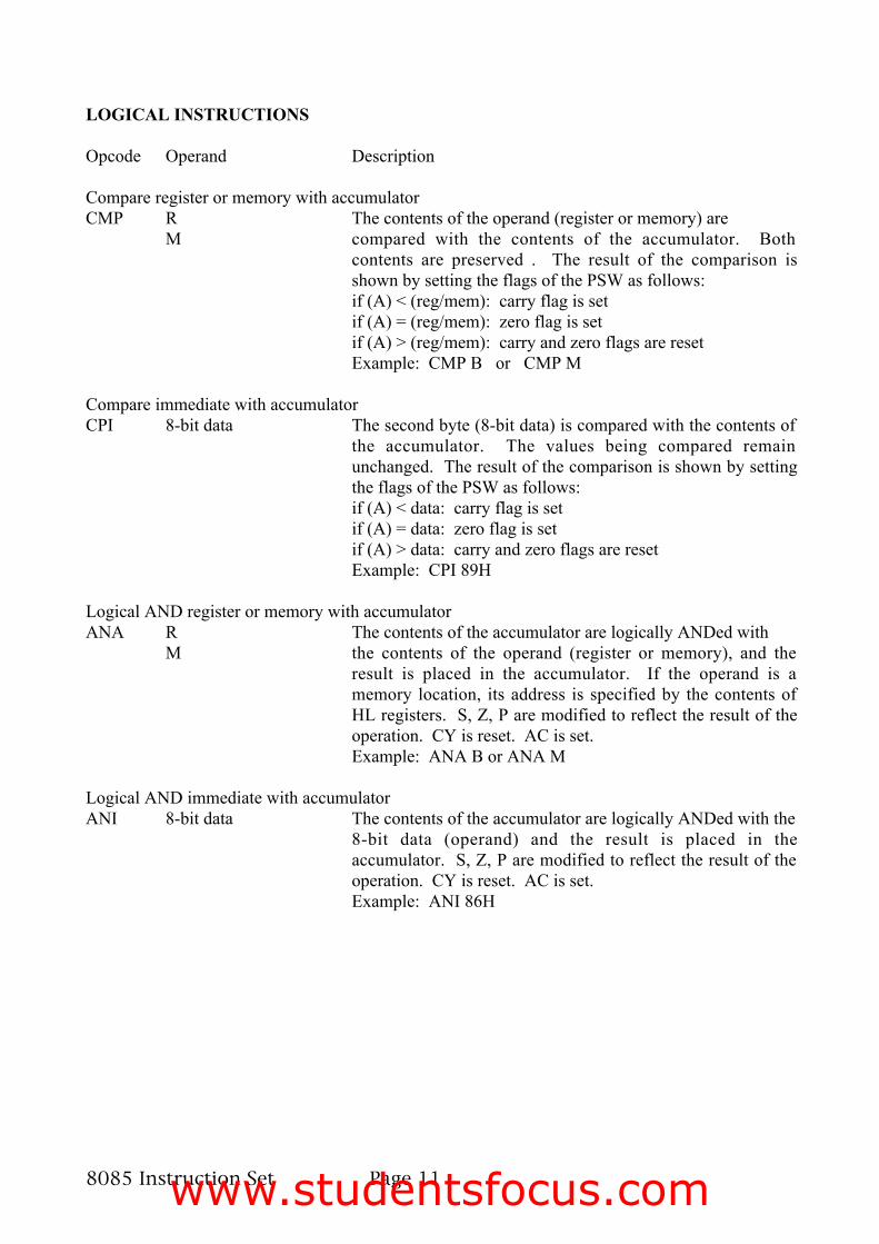
LOGICAL INSTRUCTIONS
Opcode Operand Description
Compare register or memory with accumulatorCMP R The contents of the operand (register or memory) are
M compared with the contents of the accumulator. Bothcontents are preserved . The result of the comparison isshown by setting the flags of the PSW as follows:if (A) < (reg/mem): carry flag is setif (A) = (reg/mem): zero flag is setif (A) > (reg/mem): carry and zero flags are resetExample: CMP B or CMP M
Compare immediate with accumulatorCPI 8-bit data The second byte (8-bit data) is compared with the contents of
the accumulator. The values being compared remainunchanged. The result of the comparison is shown by settingthe flags of the PSW as follows:if (A) < data: carry flag is setif (A) = data: zero flag is setif (A) > data: carry and zero flags are resetExample: CPI 89H
Logical AND register or memory with accumulatorANA R The contents of the accumulator are logically ANDed with
M the contents of the operand (register or memory), and theresult is placed in the accumulator. If the operand is amemory location, its address is specified by the contents ofHL registers. S, Z, P are modified to reflect the result of theoperation. CY is reset. AC is set.Example: ANA B or ANA M
Logical AND immediate with accumulatorANI 8-bit data The contents of the accumulator are logically ANDed with the
8-bit data (operand) and the result is placed in theaccumulator. S, Z, P are modified to reflect the result of theoperation. CY is reset. AC is set.Example: ANI 86H
www.studentsfocus.com

8085 Instruction Set Page 12
Exclusive OR register or memory with accumulatorXRA R The contents of the accumulator are Exclusive ORed with
M the contents of the operand (register or memory), and theresult is placed in the accumulator. If the operand is amemory location, its address is specified by the contents ofHL registers. S, Z, P are modified to reflect the result of theoperation. CY and AC are reset.Example: XRA B or XRA M
Exclusive OR immediate with accumulatorXRI 8-bit data The contents of the accumulator are Exclusive ORed with the
8-bit data (operand) and the result is placed in theaccumulator. S, Z, P are modified to reflect the result of theoperation. CY and AC are reset.Example: XRI 86H
Logical OR register or memory with accumulaotrORA R The contents of the accumulator are logically ORed with
M the contents of the operand (register or memory), and theresult is placed in the accumulator. If the operand is amemory location, its address is specified by the contents ofHL registers. S, Z, P are modified to reflect the result of theoperation. CY and AC are reset.Example: ORA B or ORA M
Logical OR immediate with accumulatorORI 8-bit data The contents of the accumulator are logically ORed with the
8-bit data (operand) and the result is placed in theaccumulator. S, Z, P are modified to reflect the result of theoperation. CY and AC are reset.Example: ORI 86H
Rotate accumulator leftRLC none Each binary bit of the accumulator is rotated left by one
position. Bit D7 is placed in the position of D0 as well as inthe Carry flag. CY is modified according to bit D7. S, Z, P,AC are not affected.Example: RLC
Rotate accumulator rightRRC none Each binary bit of the accumulator is rotated right by one
position. Bit D0 is placed in the position of D7 as well as inthe Carry flag. CY is modified according to bit D0. S, Z, P,AC are not affected.Example: RRC
www.studentsfocus.com

8085 Instruction Set Page 13
Rotate accumulator left through carryRAL none Each binary bit of the accumulator is rotated left by one
position through the Carry flag. Bit D7 is placed in the Carryflag, and the Carry flag is placed in the least significantposition D0. CY is modified according to bit D7. S, Z, P, ACare not affected.Example: RAL
Rotate accumulator right through carryRAR none Each binary bit of the accumulator is rotated right by one
position through the Carry flag. Bit D0 is placed in the Carryflag, and the Carry flag is placed in the most significantposition D7. CY is modified according to bit D0. S, Z, P, ACare not affected.Example: RAR
Complement accumulatorCMA none The contents of the accumulator are complemented. No flags
are affected.Example: CMA
Complement carryCMC none The Carry flag is complemented. No other flags are affected.
Example: CMC
Set CarrySTC none The Carry flag is set to 1. No other flags are affected.
Example: STC
www.studentsfocus.com

8085 Instruction Set Page 14
CONTROL INSTRUCTIONS
Opcode Operand Description
No operationNOP none No operation is performed. The instruction is fetched and
decoded. However no operation is executed.Example: NOP
Halt and enter wait stateHLT none The CPU finishes executing the current instruction and halts
any further execution. An interrupt or reset is necessary toexit from the halt state.Example: HLT
Disable interruptsDI none The interrupt enable flip-flop is reset and all the interrupts
except the TRAP are disabled. No flags are affected.Example: DI
Enable interruptsEI none The interrupt enable flip-flop is set and all interrupts are
enabled. No flags are affected. After a system reset or theacknowledgement of an interrupt, the interrupt enable flip-flop is reset, thus disabling the interrupts. This instruction isnecessary to reenable the interrupts (except TRAP).Example: EI
www.studentsfocus.com

8085 Instruction Set Page 15
Read interrupt maskRIM none This is a multipurpose instruction used to read the status of
interrupts 7.5, 6.5, 5.5 and read serial data input bit. Theinstruction loads eight bits in the accumulator with thefollowing interpretations.Example: RIM
Set interrupt maskSIM none This is a multipurpose instruction and used to implement the
8085 interrupts 7.5, 6.5, 5.5, and serial data output. Theinstruction interprets the accumulator contents as follows.Example: SIM
www.studentsfocus.com

www.studentsfocus.com

www.studentsfocus.com

www.studentsfocus.com
www.studentsfocus.com

www.studentsfocus.com

www.studentsfocus.com
www.studentsfocus.com

www.studentsfocus.com

www.studentsfocus.com

www.studentsfocus.com

www.studentsfocus.com

www.studentsfocus.com

www.studentsfocus.com

www.studentsfocus.com

www.studentsfocus.com
www.studentsfocus.com

www.studentsfocus.com

www.studentsfocus.com
www.studentsfocus.com

www.studentsfocus.com

www.studentsfocus.com

www.studentsfocus.com

www.studentsfocus.com

www.studentsfocus.com

www.studentsfocus.com

www.studentsfocus.com