instructions and parts list important safety information ... 3-in accuglide.pdf · important –...
TRANSCRIPT

3M Packaging Systems Division
3M Center, Building 220-8W-01St. Paul, MN 55144-1000
Serial No._____________________________________
For reference, record taping head(s) serial number(s) here.
Instructions and Parts List
AccuGlide IISTD 3 Inch
Upper and Lower
Taping Heads
Type 39600
TM
Read "Important Safeguards",
page 2 and also operating
"Warnings", page 7
BEFORE INSTALLING OR
OPERATING THIS
EQUIPMENT.
Important SafetyInformation
It is recommended you
immediately order the
spare parts listed on
page 17. These parts are
expected to wear through
normal use, and should
be kept on hand to minimize
production delays.
Spare Parts
AccuGlide™ is a Trademark of3M, St. Paul, MN 55144-1000
Litho in U.S.A
© 3M 1998 44-0009-1922-3(C28.0)

Replacement Parts and Service Information
3M Packaging Systems Division
3M Center, Building 220-8W-01St. Paul, MN 55144-1000
To Our Customers:This is the 3M-Matic™/AccuGlide™/Scotch™ brand equipment youordered. It has been set up and tested in the factory with "Scotch" brandtapes. If technical assistance or replacement parts are needed, call or Faxthe appropriate number listed below.
Included with each machine is an Instructions and Parts List manual.
Replacement Parts and Additional Manuals
Order parts by part number, part description and quantity required. Also,
when ordering parts and/or additional manuals, include machine name,
number and type. A parts order form is provided at the back of this manual.
3M/Tape Dispenser Parts
241 Venture Drive 1-800/344 9883
Amery, WI 54001-1325 FAX# 715/268 8153
Technical Assistance:
3M-Matic™ Helpline – 1-800/328 1390. Please provide the customer support
coordinator with the machine number, machine type/model and serial number.
If you have a technical question that does not require an immediate response,
you may Fax it to 715/381 0248.
Minimum billing on parts orders will be $25.00. Replacement part prices available on request.
Note : Outside the U.S., contact the local 3M subsidiary for parts ordering information.
$10.00 restocking charge per invoice on returned parts.
"3M-Matic", "AccuGlide" and “Scotch” are trademarks of3M, St. Paul, Minnesota 55144-1000
Printed in U.S.A.
© 3M 1999 44-0009-1851-4(E79.0)
Replacement Parts And Service Information
To Our Customers:This is the 3M-Matic™/AccuGlide™/Scotch™ brand equipment youordered. It has been set up and tested in the factory with "Scotch" brandtapes. If any problems occur when operating this equipment, and youdesire a service call, or phone consultation, call, write or Fax theappropriate number listed below.
Included with each machine is an Instructions and Parts List manual.
SERVICE, REPLACEMENT PARTS AND ADDITIONAL MANUALS
AVAILABLE DIRECT FROM:
Order parts by part number, part description and quantity required. Also, when
ordering parts and/or additional manuals, include machine name, number and
type.
1-800/328 1390
"3M-Matic", "AccuGlide" and “Scotch” are trademarks of3M, St. Paul, Minnesota 55144-1000
Printed in U.S.A.
© 3M 1999 44-0009-1852-2(D79.0)
3M Packaging Systems Division
3M Center, Building 220-8W-01St. Paul, MN 55144-1000
Instruction Manual
AccuGlide ™ II STD 3 InchUpper and Lower Taping HeadsType 39600
Table of Contents Page
Equipment Warranty and Limited Remedy ............................................................................................. ii
Taping Head Contents ............................................................................................................................ ii
Intended Use ........................................................................................................................................... 1
Important Safeguards.............................................................................................................................. 2
Specifications .......................................................................................................................................... 3 - 4Dimensional Drawing ................................................................................................................... 4
Installation ............................................................................................................................................... 5Receiving and Handling ............................................................................................................... 5Installation Guidelines .................................................................................................................. 5Tape Leg Length .......................................................................................................................... 5Tape Width Adjustment ............................................................................................................... 5
Operation ................................................................................................................................................ 6 - 8Tape Loading – Upper Taping Head ........................................................................................... 7 - 8Tape Loading – Lower Taping Head ........................................................................................... 7 - 8
Maintenance............................................................................................................................................ 9 - 10Knife Replacement ...................................................................................................................... 9Knife Guard .................................................................................................................................. 9Knife Oiler Pad............................................................................................................................. 9Cleaning ....................................................................................................................................... 9Lubrication ................................................................................................................................... 10Applying/Buffing Roller Replacement .......................................................................................... 10
Adjustments ............................................................................................................................................ 11 - 13Tape Web Alignment ................................................................................................................... 11Tape Drum Friction Brake............................................................................................................ 11Applying Mechanism Spring ........................................................................................................ 12One-Way Tension Roller ............................................................................................................. 12Tape Leg Length .......................................................................................................................... 13
Leading Tape Leg Length Adjustment .......................................................................... 13Changing Tape Leg Length From 70 to 50 mm [2-3/4 to 2 Inch] .................................. 13
Troubleshooting ...................................................................................................................................... 15 - 16Troubleshooting Guide ................................................................................................................ 15 - 16
Spare Parts/Service Information ............................................................................................................. 17Recommended Spare Parts ........................................................................................................ 17Replacement Parts and Service .................................................................................................. 17
Replacement Parts Illustrations and Parts List ............................................................... Yellow Section 18 - 35
i

Equipment Warranty and Limited Remedy: THE FOLLOWING WARRANTY IS MADE IN LIEU OF ALLOTHER WARRANTIES, EXPRESS OF IMPLIED, INCLUDING, BUT NOT LIMITED TO, THE IMPLIEDWARRANTY OF MERCHANTABILITY, THE IMPLIED WARRANTY OF FITNESS FOR A PARTICULARPURPOSE AND ANY IMPLIED WARRANTY ARISING OUT OF A COURSE OF DEALING, A CUSTOM ORUSAGE OF TRADE:
3M sells its AccuGlide ™ II STD 3 Inch Upper and Lower Taping Heads, Type 39600 with the followingwarranties:
1. The Taping Head knife, springs, and rollers will be free from all defects for ninety (90) days afterdelivery.
2. All other Taping Head parts will be free from all defects for three (3) years after delivery.If any part is proved to be defective within its warranty period, then the exclusive remedy and 3M’s and seller’ssole obligation shall be, at 3M’s option, to repair or replace the part, provided the defective part is returnedimmediately to 3M’s factory or an authorized service station designated by 3M. A part will be presumed to havebecome defective after the warranty period unless the part is received or 3M is notified of the problem no laterthan five (5) calendar days after the warranty period. If 3M is unable to repair or replace the part within areasonable time, then 3M, at its option, will replace the equipment or refund the purchase price. 3M shall have noobligation to provide or pay for the labor required to install the repaired or replacement part. 3M shall have noobligation to repair or replace (1) those parts failing due to operator misuse, carelessness, or due to anyaccidental cause other than equipment failure, or (2) parts failing due to non-lubrication, inadequate cleaning,improper operating environment, improper utilities, or operator error.
Limitation of Liability: 3M and seller shall not be liable for direct, indirect, special, incidental or consequentialdamages based upon breach of warranty, breach of contract, negligence, strict liability or any other legal theory.
The foregoing Equipment Warranty and Limited Remedy and Limitation of Liability may be changed only by awritten agreement signed by authorized officers of 3M and seller.
ii
AccuGlide ™, Scotch ™, and 3M-Matic ™ are Trademarks of 3M, St. Paul, Minnesota 55144-1000
AccuGlide ™ II STD 3 Inch Upper and Lower Taping Heads consist of:
Qty. Part Name
1 Taping Head Assembly 1 Tape Drum and Bracket Assembly 1 Hardware and Spare Parts Kit 1 Threading Tool
Taping Head Contents

1
The intended use of the AccuGlide ™ II STD 3 InchUpper and Lower Taping Heads is to apply a "C"clip of Scotch ™ brand pressure-sensitive film boxsealing tape to the top and/or bottom center seam ofregular slotted containers.
These taping heads are incorporated into moststandard 3M-Matic ™ case sealers. The compact
AccuGlide™ II STD 3 Inch Upper Taping Head , Type 39600
Intended Use
size and simplicity of the taping head also makes itsuitable for mounting in box conveying systemsother than 3M-Matic ™ case sealers. This includesreplacement of other types of taping, gluing orstapling heads in existing case sealing machines.The AccuGlide ™ II STD Taping Heads have beendesigned and tested for use with Scotch ™ brandpressure-sensitive film box sealing tape.

2
Important Safeguards
Figure 1-2 – Tape Threading Label
Figure 1-1 – Knife Warning Label
Important – In the event the following safetylabels are damaged or destroyed, they mustbe replaced to ensure operator safety .See Parts Drawing/Lists, pages 18-35 forlabel part numbers.
The “Tape Threading Label”, shown in Figure 1-2,is attached to the left side of both the upper andlower taping heads. This label provides aconvenient tape threading diagram. More detailedtape loading and threading information is providedin the "Operation" section this manual.
Turn air and electrical supplies "Off" beforeservicing the taping heads.
The “Warning-Sharp Knife” label warns operatorsand service personnel of the extremely sharp knifeused to cut the tape at the end of the box sealingoperation. The label shown in Figure 1-1 is locatedon the orange knife guard between the applyingroller assembly and the buffing roller assembly.Never operate taping heads with knife guardremoved.
Before working with the taping heads or loading/threading tape, refer to Figures 3-1 and 3-2 (page 6)to identify the knife location. Keep hands out ofthese areas except as necessary to service thetaping heads or to load/thread tape.
This safety alert symbol identifiesimportant safety messages in this
manual. READ AND UNDERSTAND THEMBEFORE INSTALLING OR OPERATINGTHIS EQUIPMENT.

3
Specifications
1. Tape:
For use with “Scotch” brand pressure-sensitive film box sealing tapes.
2. Tape Width:
48 mm [2 inches] minimum to 72 mm [3 inches] maximum.
3. Tape Roll Diameter:
Up to 405 mm [16 inches] maximum on a 76.2 mm [3 inch] diameter core.(Accommodates all system roll lengths of “Scotch” brand film tapes.)
4. Tape Application Leg Length - Standard:
70 mm ± 6 mm [2-3/4 inches ±1/4 inch]
Tape Application Leg Length - Optional:
50 mm ± 6 mm [2 inches ± 1/4 inch] (See "Adjustments – Tape Leg Length", page 13.)
5. Box Size Capacities:
For use with center seam regular slotted containers.
Minimum Maximum
Length – 150 mm [6 inches] UnlimitedHeight – 120 mm [4-3/4 inches] (most “3M-Matic” Case Sealers)
90 mm [3-1/2 inches] (with optional 2 inch leg length)Width – 150 mm [6 inches]
When upper and lower taping heads are used on “3M-Matic” case sealers, refer to the respective instructionmanual specifications for box weight and size capacities.
6. Operating Rate:
Conveyor speeds up to 0.40 m/s [80 FPM] maximum.
7. Operating Conditions:
Use in dry, relatively clean environments at 5° to 40° C [40° to 105° F] with clean dry boxes.
Important – Taping heads should not be washed down or subjected to conditions causing moisturecondensation on components.
7. Taping Head Dimensions:
Length – 457 mm [18 inches]Height – 560 mm [22 inches] (with tape drum)Width – 130 mm [5-1/8 inches] (without mounting spacers)Weight – Packaged: 8.6 kg [19 lbs.] Unpackaged: 7.7 kg [17 lbs.]
Limited byCase Sealer

4Figure 2-1 – Dimensional Drawing
Specifications (Continued)

5
Installation
1. The box conveying system must positivelypropel the box in a continuous motion, notexceeding 0.40 m/s [80 feet per minute], pastthe taping head assembly since the box motionactuates the taping mechanism.
2. If a pusher or cleated conveyor is being used,steps should be taken in the conveyor design toprevent the pusher from contacting theapplying or buffing roller arms resulting indamage to the taping head.
WARNING – Taping Heads are equipped with an extremely sharp tape cut-off knife. Theknife is located under the orange knife guard which has the "Warning – Sharp Knife" label.
Before working with the taping heads or loading tape, refer to Figures 3-1 and 3-2 on page 6 andidentify the knife location. Keep hands out of these areas except as necessary to service the tapingheads.
Receiving And Handling
After the taping head assembly has beenunpackaged, examine the unit for damage that mighthave occurred during transit. If damage is evident,file a damage claim immediately with thetransportation company and also notify your 3MRepresentative.
Installation Guidelines
The taping head assembly can be used inconverting existing or in custom made machinery.It can be mounted for top taping or bottom taping.Refer to box size specifications on page 3, andFigure 2-1 on page 4, for the following points inmaking such installations:
3. Figure 2-1 illustrates the typical mountingrelationship for opposing taping headassemblies to allow taping of box heights downto 90 mm [3-1/2 inches]. To tape box heightsdown to 70 mm [2-3/4 inches], the tapingheads must be completely staggered so onlyone tape seal is being applied at one time.
Note – AccuGlide™ II STD taping Heads aresupplied with a buffing arm guard. This guardmay have to be removed to install the tapinghead into some older design 3M-Matic™ casesealers. If this is the case, remove the fourguard mounting screws, remove the guard andthen install the taping head.
4. Mounting studs are provided with the tapinghead, but special installations may requirealternate means for mounting.
5. Box hold-down or guide skis should be providedand the taping head mounted so that the sideplates are 6 mm [1/4 inch] maximum away fromthe ski surface on which the box rides.
CAUTION – Taping head weighsapproximately 7.7 kg [17 lbs]
without tape. Remove tape roll beforeremoving taping head from machine tominimize weight. Use proper bodymechanics when installing or removingtaping head.
Tape Leg Length
Taping heads are factory set to apply standard70 mm [2-3/4 inch] tape legs. The heads can beconverted to apply 50 mm [2 inch] tape legs ifdesired but both upper and lower heads must be setto apply the same tape leg length. See"Adjustments – Changing Tape Leg Length From70 to 50 mm [2-3/4 to 2 Inches]", page 13.
Also, the conveyor speed at which the productmoves through the taping heads, affects the leadingand trailing tape leg length. See, "Adjustments –Leading Tape Leg Length Adjustment", page 13.
Tape Width Adjustment
Taping heads are factory set to apply 72 mm [3 inch]wide tape. If it is necessary to align the tape or toapply narrower tapes, refer to "Adjustments – TapeWeb Alignment", page 11 for set-up procedure.

6
Figure 3-2 – Taping Head Components/Threading Diagram – Lower Head (Left Side View)
Figure 3-1 – Taping Head Components/Threading Diagram, Upper Head (Left Side View)
Operation
7
It is recommended that the detailed instructions andsketches in this manual be referred to the first fewtimes the taping head is loaded/threaded until theoperator becomes thoroughly familiar with the tapeloading operation.
WARNINGS
1. Turn air and electrical supplies off and disconnect before servicing taping heads.
2. Never attempt to work on the taping heads or load tape when the box drive system is running.
3. Taping heads are equipped with an extremely sharp cut-off knife. Before working with thetaping heads or attempting to load/thread tape, refer to Figures 3-1 and 3-2 and identify theknife location. Keep hands out of these areas except as necessary to service the tapingheads.
4. Failure to comply with these warnings can result in severe personal injury and/or equipmentdamage.
Operation (Continued)
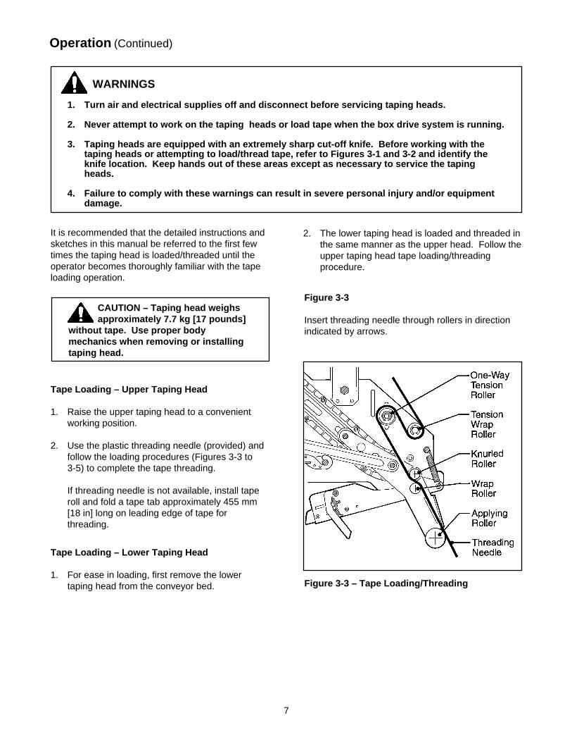
2. The lower taping head is loaded and threaded inthe same manner as the upper head. Follow theupper taping head tape loading/threadingprocedure.
Figure 3-3
Insert threading needle through rollers in directionindicated by arrows.
CAUTION – Taping head weighsapproximately 7.7 kg [17 pounds]
without tape. Use proper bodymechanics when removing or installingtaping head.
Tape Loading – Lower Taping Head
1. For ease in loading, first remove the lowertaping head from the conveyor bed.
Tape Loading – Upper Taping Head
1. Raise the upper taping head to a convenientworking position.
2. Use the plastic threading needle (provided) andfollow the loading procedures (Figures 3-3 to3-5) to complete the tape threading.
If threading needle is not available, install taperoll and fold a tape tab approximately 455 mm[18 in] long on leading edge of tape forthreading.
Figure 3-3 – Tape Loading/Threading

8
Operation (Continued)
Manually turn tape roll to create slack tape whilepulling threading needle through tape applyingmechanism until needle is through and tape is inalignment with applying roller.
Excess tape can be cut with a scissors at applyingroller.
WARNING – Use care when workingnear tape cut-off knife as knife is
extremely sharp. If care is not taken, severepersonal injury could result.
Figure 3-5
Figure 3-4
Place tape roll on tape drum to dispense tape withadhesive side forward. Seat tape roll fully againstback flange of drum. Adhere tape lead end tothreading needle as shown.
Figure 3-5 – Tape Loading/Threading
Figure 3-4 – Tape Loading/Threading

9
WARNINGS
1. Turn air and electrical supplies off and disconnect before beginning maintenance.
2. Use care when working near tape cut-off knife as knife is extremely sharp.
3. Failure to comply with these warnings could result in severe personal injury or equipmentdamage.
The AccuGlide™ STD II 3 Inch Taping Head hasbeen designed for long, trouble free service. Thetaping head will perform best when it receivesroutine maintenance and cleaning. Taping headcomponents that fail or wear excessively should bepromptly repaired or replaced to prevent damage toother portions of the head or to the product.
Knife Replacement , Upper and Lower TapingHeads – Figure 4-1
1. Loosen, but do not remove, the knife screws(A). Remove and discard old knife.
2. Mount the new knife (B) with the beveled sideaway from the knife holder.
3. Bottom the knife slots against the screws. (Thiswill position the knife at the correct angle.)Tighten the knife screws to secure the knife.
Maintenance
Note – Check the knife position to insureproper clearance between knife and guardby slowly pivoting the knife guard back.
Figure 4-1 – Knife Replacement
Knife Guard
The knife guard covers the knife whenever a box isnot being taped. Periodically check to be sure theknife guard is functioning properly and returning tocover the knife. Replace any defective parts.
Knife Oiler Pad
The taping heads are equipped with a felt oiler padthat has been pre-lubricated at the factory toprovide a film of oil on the cutting edge of the knifeto reduce adhesive build-up. Apply SAE #30 non-detergent oil as needed. Saturate felt oiler pad.
Should tape adhesive build-up occur on knife,carefully wipe clean with an oily cloth.
Cleaning
Regular slotted containers produce a great deal ofdust and paper chips when conveyed throughtaping heads. If this dust is allowed to build-up onthe heads, it can cause wear on the moving parts.Excessive dirt build-up should be wiped off with adamp cloth. Cleaning should be done once permonth, depending on the number and type of boxesused. If the boxes used are dirty, or if theenvironment in which the heads operate is dusty,cleaning on a more frequent basis may benecessary.
Note – Never attempt to remove dirt fromtaping heads by blowing it out with compressedair. This can cause the dirt to be blown insidethe components onto sliding surfaces. Dirt inthese areas can cause serious equipmentdamage. Never wash down or subject tapingheads to conditions causing moisturecondensation on components. Seriousequipment damage could result.
10
WARNINGS
1. Turn air and electrical supplies off and disconnect before beginning maintenance.
2. Use care when working near tape cut-off knife as knife is extremely sharp.
3. Failure to comply with these warnings could result in severe personal injury or equipmentdamage.
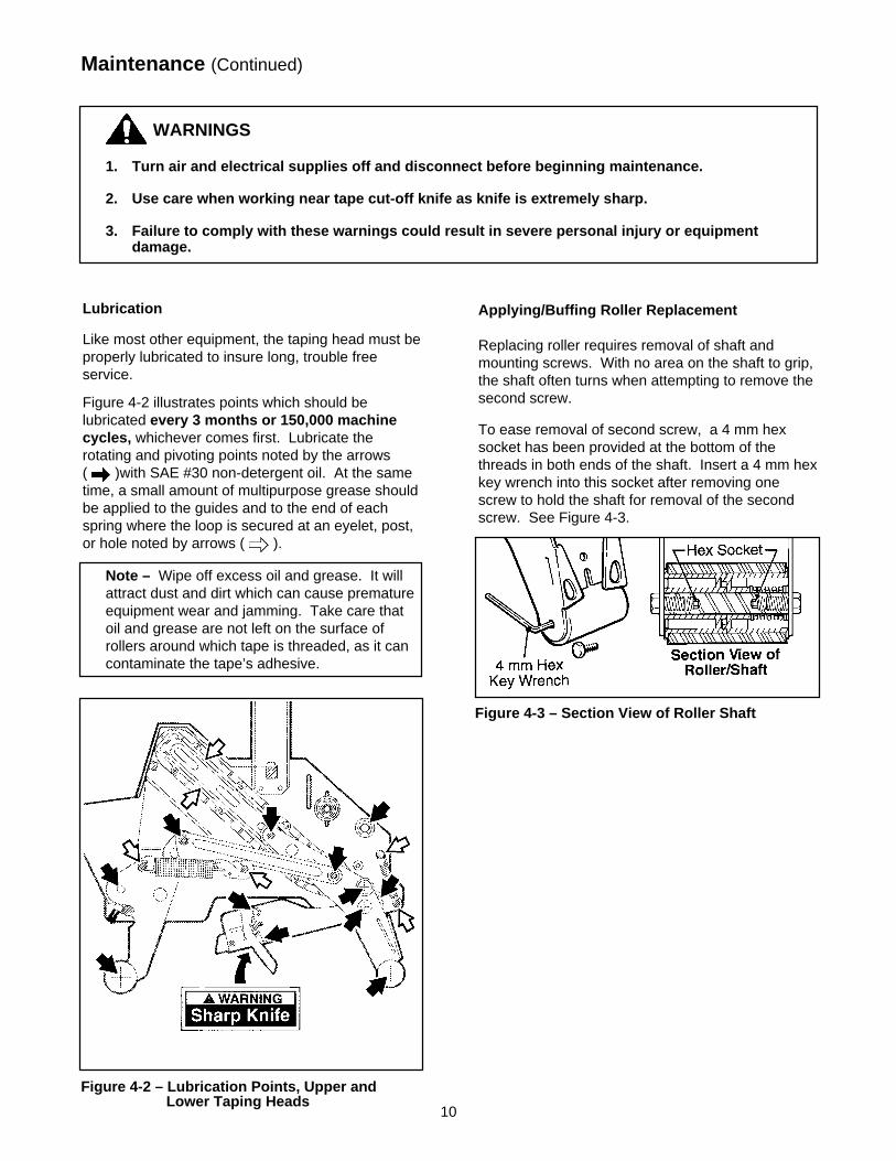
Lubrication
Like most other equipment, the taping head must beproperly lubricated to insure long, trouble freeservice.
Figure 4-2 illustrates points which should belubricated every 3 months or 150,000 machinecycles, whichever comes first. Lubricate therotating and pivoting points noted by the arrows( )with SAE #30 non-detergent oil. At the sametime, a small amount of multipurpose grease shouldbe applied to the guides and to the end of eachspring where the loop is secured at an eyelet, post,or hole noted by arrows ( ).
Maintenance (Continued)
Note – Wipe off excess oil and grease. It willattract dust and dirt which can cause prematureequipment wear and jamming. Take care thatoil and grease are not left on the surface ofrollers around which tape is threaded, as it cancontaminate the tape’s adhesive.
Figure 4-2 – Lubrication Points, Upper and Lower Taping Heads
Figure 4-3 – Section View of Roller Shaft
Applying/Buffing Roller Replacement
Replacing roller requires removal of shaft andmounting screws. With no area on the shaft to grip,the shaft often turns when attempting to remove thesecond screw.
To ease removal of second screw, a 4 mm hexsocket has been provided at the bottom of thethreads in both ends of the shaft. Insert a 4 mm hexkey wrench into this socket after removing onescrew to hold the shaft for removal of the secondscrew. See Figure 4-3.
11
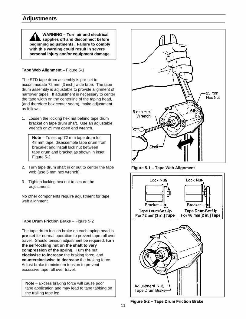
Tape Drum Friction Brake – Figure 5-2
The tape drum friction brake on each taping head ispre-set for normal operation to prevent tape roll overtravel. Should tension adjustment be required, turnthe self-locking nut on the shaft to varycompression of the spring. Turn the nutclockwise to increase the braking force, andcounterclockwise to decrease the braking force.Adjust brake to minimum tension to preventexcessive tape roll over travel.
Tape Web Alignment – Figure 5-1
The STD tape drum assembly is pre-set toaccommodate 72 mm [3 inch] wide tape. The tapedrum assembly is adjustable to provide alignment ofnarrower tapes. If adjustment is necessary to centerthe tape width on the centerline of the taping head,(and therefore box center seam), make adjustmentas follows:
1. Loosen the locking hex nut behind tape drumbracket on tape drum shaft. Use an adjustablewrench or 25 mm open end wrench.
Note – Excess braking force will cause poortape application and may lead to tape tabbing onthe trailing tape leg.
Adjustments
WARNING – Turn air and electricalsupplies off and disconnect before
beginning adjustments. Failure to complywith this warning could result in severepersonal injury and/or equipment damage.
Figure 5-1 – Tape Web Alignment
Figure 5-2 – Tape Drum Friction Brake
2. Turn tape drum shaft in or out to center the tapeweb (use 5 mm hex wrench).
3. Tighten locking hex nut to secure theadjustment.
No other components require adjustment for tapeweb alignment.
Note – To set up 72 mm tape drum for48 mm tape, disassemble tape drum frombracaket and install lock nut betweentape drum and bracket as shown in inset,Figure 5-2.

12
Adjustments (Continued)
Figure 5-4 – One-Way Tension Roller
Applying Mechanism Spring
To obtain access to the spring, remove the tapinghead cover (four mounting screws). Replace coverwhen finished.
The applying mechanism spring, shown inFigures 3-1 and 3-2, controls applying and buffingroller pressure on the box and returns themechanism to the reset position. The springpressure is pre-set, as shown in Figure 5-3A fornormal operation, but is adjustable.
If a tape gap appears on the trailing surface of thebox increase spring pressure. If the front of the boxis being crushed by the applying roller decreasespring pressure.
Removing the spring end loop from the spring holderand placing loop in other holes provided, as shownin Figure 5-3B, will adjust the spring pressure.
WARNING – Turn air and electricalsupplies off and disconnect before
beginning adjustments. Failure to complywith this warning could result in severepersonal injury and/or equipment damage.
Figure 5-3 – Applying Mechanism Spring
To Adjust Tension:
1. Wrap a cord or small strap (non-adhesive) 4-6turns around the tension roller.
2. Attach a spring scale to the end of the cord orstrap.
3. Turn the adjusting nut with the socket wrenchprovided, until a force of approximately 0.5 kg to0.9 kg [1 to 2 lbs.] is required to turn the roller bypulling on the spring scale.
One-Way Tension Roller
Figure 5-4
The one-way tension roller is factory set. Whenreplacing this assembly, the roller must have0,5 kg [1 lb.] minimum tangential force when turning.

13
Tape Leg Length
WARNING – Use care when workingnear cut-off knife as knife is
extremely sharp. If care is not taken,severe injury could result.
1. Remove and retain two hex head screws andremove the brush from normal position “A” onside frame.
2. Remount and secure brush in position “A-A” onside frame forward of normal location usingoriginal fasteners.
3. Remove cut-off bracket extensions from position"B".
4. Remount cut-off bracket extensions in forwardposition “B-B”.
5. Remove and retain the one-way tension rollerassembly from slot “C” in frame.
6. Remount tension roller assembly near top of slot“C-C” in frame using original fasteners.
7. Adjust tension roller according to "Leading TapeLeg Length Adjustment" above.
LEADING TAPE LEG LENGTH ADJUSTMENT –Figure 5-5
The one-way tension roller position is adjustable tocontrol the leading tape leg length.
Moving this roller farther away from the box top orbottom surface will decrease the leading leg length.Moving it closer to the box top or bottom surface willincrease the leading leg length.
CHANGING TAPE LEG LENGTH FROM 70 to 50 mm[2-3/4 TO 2 INCHES] – Figure 5-6
Note – When changing tape leg length, bothupper and lower heads must be adjusted toapply the same leg lengths.
Adjustments (Continued)|
Figure 5-5 – Leading Tape Leg Length
Figure 5-6 – Changing Tape Leg Length
WARNING – Turn air and electricalsupplies off and disconnect before
beginning adjustments. Failure to complywith this warning could result in severepersonal injury and/or equipment damage.

14
THIS PAGE IS BLANK

15
(Continued)
Troubleshooting
Cause
The tape is threaded incorrectly
The tape tension is too low
The knurled roller drags
Tape tracks to one side or dragson the support tabs of applyingframe
The one-way tension roller is notcorrectly positioned
Taping head is not set up properly
The knife is dull and/or has brokenteeth
Tape tension is insufficient
Adhesive has built up on the knife
The knife is not positionedproperly
The knife is dry
The knife is in backwards
One or both cutter springs aremissing or stretched
Tension roller surface is not fullycontacting the taping head frame
Correction
The tape must go around the wraproller before going around theone-way tension roller
Adjust the one-way tension roller
Check for adhesive build-upbetween the knurled roller and itsshaft. Clean and lubricate shaft.Remove all lubricant from rollersurfaces.
Adjust the tape web alignments
Position the roller in its mountingslot so that the tape extends justbeyond the centerline of theapplying roller
Check leg length adjustments
Replace the knife
Increase tape tension by adjustingthe one-way tension roller
Clean and adjust the knife
Make sure the knife is bottomedout against the mounting bolts
Lubricate the knife oiler pad on theknife guard
Mount the knife so that thebeveled edge is away from theentrance of the head
Replace the defective spring(s)
Make sure one-way bearing isbelow the surface of the tensionroller. If not, press bearing furtherinto roller or replace roller.
Troubleshooting Guide
Problem
The tape leg on the front of thecase is too long
The knife does not cut tape or thetape end is jagged or shredded

16
Problem
Tape is tabbing on the trailing legon the back of the box
The tape end does not stay inapplication position in front of theapplying roller
Tape not centered on box seam
Cause
There is excess tension on thetape drum assembly and/or theone-way tension roller assembly
Rollers in the tape path do notrotate freely
The knife is not cutting tapeproperly
The tape is threaded incorrectly
Applying mechanism spring hastoo little tension
The tape is incorrectly threaded
Flanged knurled roller overruns onreturn of applying mechanism toits rest position
Applying roller overruns on returnof applying mechanism to its restposition
The one-way tension roller is notcorrectly positioned
The one-way tension roller isdefective
Tape drum not centered
Centering guides not centered
Box flaps not of equal length
Correction
Adjust the one-way tension rollerand/or the tape drum assembly
Clean adhesive deposits from thesurface, ends, and shafts of therollers. Then lubricate rollershafts. Remove all lubricant fromroller surfaces.
Refer to tape cutting problems
Rethread the tape
Move spring hook to next tighterhole
Rethread the tape
Adjust tension roller position inmounting slot to lengthen tape leg
There should be a slight dragwhen rotating the applying roller.If not, check friction springs and/orfriction pins and replace ifnecessary
Position roller in it mounting slotso that tape end extends beyondcenterline of applying roller
Replace the one-way tensionroller
Reposition tape drum
Adjust centering guides
Check box specifications
Troubleshooting Guide
Troubleshooting (Continued)

17
Spare Parts/Service Information
Recommended Spare Parts
A set of spare parts that will periodically require replacement due to normal wear is supplied with the tapingheads. The set includes the following which should be reordered when used to keep the taping heads inproduction:
AccuGlide™ II STD 3 Inch Upper Taping HeadQty. Ref. No. Part Number Description
4 2948-22 78-8076-4500-3 Stud – Mounting1 2950-10 78-8070-1274-1 Spring – Upper Extension (Silver)1 2952-2 78-8028-7899-7 Knife – 89 mm/3.5 Inch2 2952-12 78-8052-6602-6 Spring – Cutter1 – 78-8076-4726-4 Tool – Tape Threading
AccuGlide™ II STD 3 Inch Lower Taping HeadQty. Ref. No. Part Number Description
1 2952-2 78-8028-7899-7 Knife – 89 mm/3.5 Inch2 2952-12 78-8052-6602-6 Spring – Cutter4 2954-22 78-8076-4500-3 Stud – Mounting1 2955-10 78-8070-1273-3 Spring – Lower Extension (Black)1 – 78-8076-4726-4 Tool – Tape Threading
In addition to the above set of spare parts supplied with the taping head, it is suggested that the following spareparts be maintained which will require replacement under normal wear of the taping head.
Qty. Ref. No. Part Number Description
1 2949-15 78-8057-6181-0 Roller – Applying1 2950/2955-5 78-8057-6180-2 Roller – Buffing1 2952-18 78-8113-7030-9 Spring – Torsion
Replacement Parts and Service
Refer to the first page of this instruction manual “Replacement Parts and Service Information".
18
Replacement Parts Illustrations and Parts ListsAccuGlide™ II STD 3 Inch Upper Taping Head, Type 39600AccuGlide™ II STD 3 Inch Lower Taping Head, Type 39600
1. Refer to Taping Head Assemblies Figure, page 19 to find all the parts illustrations identified by figurenumbers.
2. Refer to the figure or figures to determine the individual parts required and the parts reference number.
3 . The replacement parts list, that follows each illustration, includes the part number and part descriptionfor the parts in that illustration.
Note – The complete description has been included for standard fasteners and some commerciallyavailable components. This has been done to allow obtaining these standard parts locally, should thecustomer elect to do so.
4. Refer to the first page of this instruction manual "Replacement Parts and Service Information" forreplacement parts ordering information.
IMPORTANT – Not all the parts listed are normally stocked items. Some parts or assembliesshown are available only on a special order basis. Contact 3M/Tape Dispenser Parts toconfirm item availability.

19
Taping Head Assemblies – AccuGlide ™ II STD 3 Inch

20
Figure 2948 – Upper Head

21
Figure 2948 – Upper Head
Ref. No. 3M Part No. Description
2948-1 78-8070-1386-3 Frame – Tape Mount Upper Assembly
2948-2 78-8070-1387-1 Frame – Front Upper Assembly
2948-3 78-8068-4143-9 Guide – #1
2948-4 78-8068-4144-7 Guide – #2
2948-5 83-0002-7336-3 Screw – Hex Hd, M4 x 14
2948-6 78-8010-7416-8 Nut – Hex Jam, M4
2948-7 78-8076-4735-5 Spacer – Spring
2948-8 78-8055-0694-2 Spacer – 10 x 10 x 115 mm
2948-9 78-8060-7939-4 Spacer – 10 x 115 W/Slots
2948-10 78-8060-7936-0 Brush Assembly
2948-11 78-8054-8796-0 Shaft – Tension Roller
2948-12 78-8054-8798-6 Shaft – Wrap Roller
2948-13 26-1003-5829-5 Screw – Hex Hd, M6 x 12
2948-15 78-8100-1009-6 Washer – Special
2948-16 78-8054-8797-8 Roller – Top Tension
2948-17 78-8052-6566-3 Washer – Friction
2948-18 78-8052-6567-1 Spring – Compression
2948-19 78-8017-9077-1 Nut – Self Locking, M10 x 1
2948-20 78-8054-8799-4 Roller – Wrap
2948-21 26-1000-1613-3 Ring – Retaining, Tru-Arc #1-420-0120-100
2948-22 78-8076-4500-3 Stud – Mounting
2948-23 78-8060-7937-8 Spacer – 6,5/14 x 12,5
2948-24 78-8060-7938-6 Screw – Low Profile, M6 x 25
2948-25 78-8076-5242-1 Stop – Cut-Off Frame
2948-26 78-8060-8179-6 Screw – Flat Head Hex, M6 x 20
2948-27 78-8076-5477-3 Washer – Special, 6.5 x 20 x 4
2948-28 78-8100-1049-2 Guard – Head
2948-29 78-8060-8087-1 Screw – M5 x 10
2948-30 78-8005-5741-1 Washer – Flat, M5
2948-31 78-8076-4734-8 Bumper
2948-32 78-8070-1365-7 Label – Threading, English Language

22
Figure 2949 – Upper and Lower Heads
23
Figure 2949 – Upper and Lower Heads
Ref. No. 3M Part No. Description
2949-1 78-8100-0982-5 Arm – Applying, R/H
2949-2 78-8100-0983-3 Arm – Applying, L/H
2949-3 78-8070-1292-3 Plate – Back-Up
2949-4 78-8076-4736-3 Shaft Roller
2949-5 78-8076-4737-1 Roller Assembly – Knurled
2949-6 78-8076-4738-9 Roller – Wrap
2949-7 78-8054-8806-7 Spacer
2949-8 78-8017-9082-1 Bearing – Special, 30 mm
2949-9 78-8017-9106-8 Screw – Bearing Shoulder
2949-10 78-8054-8801-8 Shaft – 10 x 85, W/Hexagon
2949-11 78-8017-9074-8 Washer – Nylon, 15 mm
2949-12 78-8052-6566-3 Washer – Friction
2949-13 78-8052-6567-1 Spring – Compression
2949-14 78-8060-8396-6 Bushing – Applying Roller
2949-15 78-8057-6181-0 Roller – Applying
2949-16 26-1003-5829-5 Screw – Hex Hd, M6 x 12

24
Figure 2950 – Upper Head
25
Figure 2950 – Upper Head
Ref. No. 3M Part No. Description
2950-1 78-8070-1392-1 Buffing Arm – Sub Assembly
2950-2 78-8070-1391-3 Buffing Arm – Sub Assembly
2950-3 78-8091-0799-4 Shaft – 10 x 85, W/Hexagon
2950-4 78-8054-8807-5 Bushing – Buffing Roller
2950-5 78-8057-6180-2 Roller – Buffing
2950-7 78-8076-4739-7 Spacer – Spring
2950-8 78-8028-7885-6 Shaft – 10 x 115 mm
2950-9 26-1003-5829-5 Screw – Hex Hd, M6 x 12
2950-10 78-8070-1274-1 Spring – Upper (Silver)
2950-11 78-8070-1244-4 Holder – Spring

26
Figure 2951 – Upper and Lower Heads

27
Ref. No. 3M Part No. Description
2951-1 78-8070-1388-9 Link – Arm Bushing Assembly
2951-2 78-8070-1389-7 Link – Arm Bushing Assembly
2951-3 78-8076-4740-5 Shaft – Pivot
2951-4 78-8017-9082-1 Bearing – Special 30 mm
2951-5 78-8017-9106-8 Screw – Bearing Shoulder
2951-6 26-1003-5829-5 Screw – Hex Hd, M6 x 12
Figure 2951 – Upper and Lower Heads
28
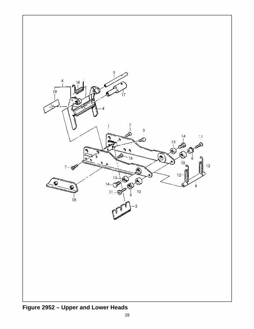
Figure 2952 – Upper and Lower Heads

29
Figure 2952 – Upper and Lower Heads
Ref. No. 3M Part No. Description
2952-1 78-8070-1283-2 Frame – Cut-Off
2952-2 78-8028-7899-7 Knife – 89 mm/3.5 Inch
2952-3 26-1002-5817-2 Screw – Hex Hd, M5 x 8
2952-4 78-8076-4741-3 Knife Guard Assembly – W/English Language Label
2952-5 78-8054-8813-3 Shaft – Knife Guard
2952-7 26-1005-4758-2 Screw – Flat Hd, Soc Dr, M4 x 10
2952-8 78-8060-7941-0 Pin – Spring Holder W/Slots
2952-9 78-8052-6600-0 Spacer
2952-10 78-8070-1269-1 Bumper
2952-11 26-1005-4757-4 Screw – Flat Hd, Soc Dr, M5 x 20
2952-12 78-8052-6602-6 Spring – Cutter
2952-13 78-8017-9132-4 Pivot – Cutter Lever
2952-14 26-1003-5828-7 Screw – Spec, Hex Hd, M6 x 10
2952-15 78-8070-1216-2 Slide – Extension
2952-16 26-1008-6574-5 Screw – Flat Hd, Phil Dr, M4 x 10
2952-17 78-8113-7060-6 Bushing – 83.7 mm Long
2952-18 78-8113-7030-9 Spring – Torsion
2952-19 78-8070-1335-0 Label – Warning, English

30
Figure 2953 – Upper and Lower Heads

31
Figure 2953 – Upper and Lower Heads
Ref. No. 3M Part No. Description
2953-1 78-8070-1395-4 Bracket – Bushing Assembly
2953-2 78-8060-8462-6 Shaft – Tape Drum, 3 Inch Head
2953-3 78-8017-9169-6 Nut – M18 x 1
2953-4 78-8076-4731-4 Tape Drum Assembly – 3 Inch Wide
2953-5 78-8054-8815-8 Tape Drum Assembly
2953-6 78-8054-8816-6 Leaf Spring
2953-7 26-1002-5753-9 Screw – Self Tapping
2953-8 78-8060-8172-1 Washer – Friction
2953-9 78-8052-6271-0 Washer – Tape Drum
2953-10 78-8100-1048-4 Spring – Core Holder
2953-11 78-8017-9077-1 Nut – Self Locking, M10 x 1
2953-12 78-8100-1050-0 Spacer – Bracket
2953-13 26-1003-5829-5 Screw – Hex Hd, M6 x 12
2953-14 78-8076-4732-2 Tape Drum Assembly – 3 Inch Head
2953-15 26-1004-5510-9 Washer – Plain, M10

32
Figure 2954 – Lower Head

33
Figure 2954 – Lower Head
Ref. No. 3M Part No. Description
2954-1 78-8070-1369-9 Frame – Tape Mount Lower Assembly
2954-2 78-8070-1370-7 Frame – Front Lower Assembly
2954-3 78-8068-4144-7 Guide – #2
2954-4 78-8068-4143-9 Guide – #1
2954-5 83-0002-7336-3 Screw – Hex Hd, M4 x 14
2954-6 78-8010-7416-8 Nut – Hex, M4
2954-7 78-8076-4735-5 Spacer – Spring
2954-8 78-8055-0694-2 Spacer – 10 x 10 x 115 mm
2954-9 78-8060-7939-4 Spacer – 10 x 115, W/Slots
2954-10 78-8060-7936-0 Brush Assembly
2954-11 78-8054-8796-0 Shaft – Tension Roller
2954-12 78-8054-8798-6 Shaft – Wrap Roller
2954-13 26-1003-5829-5 Screw – Hex Hd, M6 x 12
2954-15 78-8100-1009-6 Washer – Special
2954-16 78-8054-8817-4 Roller – Tension Bottom
2954-17 78-8052-6566-3 Washer – Friction
2954-18 78-8052-6567-1 Spring – Compression
2954-19 78-8017-9077-1 Nut – Self Locking, M10 x 1
2954-20 78-8054-8799-4 Roller – Wrap
2954-21 26-1000-1613-3 Ring – Retaining, Tru-Arc #1-420-0120-100
2954-22 78-8076-4500-3 Stud – Mounting
2954-23 78-8060-7937-8 Spacer – 6,5/14 x 12,5
2954-24 78-8060-7938-6 Screw – Low Profile, M6 x 25
2954-25 78-8076-5242-1 Stop – Cut-Off Frame
2954-26 78-8060-8179-6 Screw – Flat Head Hex, M6 x 20
2954-27 78-8076-5477-3 Washer – Special /6.5 x 20 x 4
2954-28 78-8100-1049-2 Guard – Head
2954-29 78-8060-8087-1 Screw – M5 x 10
2954-30 78-8005-5741-1 Washer – Flat, M5
2954-31 78-8076-4734-8 Bumper
2954-32 78-8070-1364-0 Label – Threading, English Language

34
Figure 2955 – Lower Head

35
Figure 2955 – Lower Head
Ref. No. 3M Part No. Description
2955-1 78-8070-1391-3 Buffing Arm Sub Assembly
2955-2 78-8070-1392-1 Buffing Arm Sub Assembly
2955-3 78-8091-0799-4 Shaft – 10 x 85, W/Hexagon
2955-4 78-8054-8807-5 Bushing – Buffing Roller
2955-5 78-8057-6180-2 Roller – Buffing
2955-7 78-8076-4739-7 Spacer – Spring
2955-8 78-8028-7885-6 Shaft – 10 x 115 mm
2955-9 26-1003-5829-5 Screw – Hex Hd, M6 x 12
2955-10 78-8070-1273-3 Spring – Lower (Black)
2955-11 78-8070-1244-4 Holder – Spring