instructions for constructing grey walter’s tortoise robot
TRANSCRIPT

Instructions For Constructing Grey Walter’s Tortoise Robot From LEGO Mindstorms Components
Michael R.W. Dawson, Biological Computation Project,
University of Alberta, Edmonton, Alberta
December, 2004

Constructing A Grey Walter Tortoise Page 1
Introduction
The purpose of this document is to describe how to construct a particular robot, which we will call a Grey Walter Tortoise, out of Lego Mindstorms or Lego Dacta components.
This particular robot was inspired by some of the original work on autonomous robots that was accomplished by William Grey Walter in the late 1940s in Bristol (Grey Walter, 1950, 1951, 1963) In the original description of this kind of system, the robot was a tricycle-like vehicle. A rear motor powered the robot forward by driving two rear wheels. A front motor steered the robot by turning the front wheel. A light sensor controlled the steering. Under dark conditions, the robot moved forward and slowly turned, seeking light. In medium light conditions, the steering motor stopped, and the robot moved towards the light. In bright conditions, the steering motor was run at double speed, leading to “dazzled” avoiding behavior. The robot was surrounded by a transparent shell (hence its name). When the shell was bumped, the avoiding behavior was initiated as well. Some excellent photographs of the original robots and their behavior can be found at the following web page:
http://www.ias.uwe.ac.uk/extra_pages/gwonline.html.
The current version of the robot that is described in this document is a functional approximation of Grey Walter’s original machines. It is constructed from parts in a LEGO Dacta kit that was purchased for the Biological Computation Project at the University of Alberta; these parts are identical to those that are easily found in LEGO Mindstorms kits. The instructions that are provided below for building the robot describe the fourth generation of this robot. This generation of the robot differs from earlier generations in terms of incorporating a few more of the principles of LEGO design that are intended to create stronger robots (Martin, 1995). Also, the front motor assembly has been changed to gear down the rotation of the front axle that steers the robot. Finally, instructions for completing the “shell” of the tortoise have been completed. The images that are provided below to show how the robot was constructed were created using a suite of LEGO CAD programs (in particular, MLCAD, L3P, POV-RAY, and LPUB) (Clague, Agullo, & Hassing, 2002). The use of plates and beams to restrict
the sight line of the light sensors can be found elsewhere (Baum, 2003).
Because the robot is constructed from LEGO components, the robot is not intended to be an exact duplicate of the original. We have attempted to create a robot that has similar sensor capabilities to the original, and have programmed its behavior using Not Quite C (NQC). NQC is available from the following web page:
http://bricxcc.sourceforge.net/nqc/.
The instructional images in this document were constructed with the Ldraw suiteof programs, which are available at:
http://www.ldraw.org/
At this time of writing, we have not compiled video footage of the behavior of this generation of tortoise. However, several examples of the behavior of previous generations of this machine that we have explored can be viewed at the following web page:
http://www.bcp.psych.ualberta.ca/~mike/Book2/Robots/Walter/index.html.
By the end of the winter of 2005, it is hoped that some new videos of the current generation of robots will be available.
Constructing A Grey Walter Tortoise Page 1
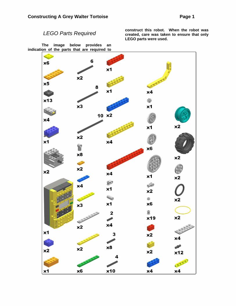
LEGO Parts Required
The image below provides an indication of the parts that are required to
construct this robot. When the robot was created, care was taken to ensure that only LEGO parts were used.

Constructing A Grey Walter Tortoise Page 2
Stage 1 – Build The Left Side The first stage in constructing this
robot is to build the left side of fits chassis, which is illustrated below. The constructed side can be considered to be a beam that is 24 LEGO studs long. The beam is reinforced by two 4-stud beams attached to either end, in accordance with Martin’s paper The art of LEGO design. An 8-stud beam is attached to the side to provide support for an axle that is attached later.
Step 1: Lay two beams end to end to create a 1 X 24 length
Step 2: Attach a layer of plates to the beams to hold them together. Don’t overlap a seam
between plates with the seam between the two beams.
Step 3: Attach another layer of plates to the previous layer, once again avoiding the
overlapping of seams between adjacent layers
Step 4: Attach a final layer of beams to the top layer of plates.
Step 5: Insert 6 black pegs to be used to attach shorter beams to the side
Step 6: Attach a 1X4 beam to each end of the side using the black pegs
Step 7: Attach a 1X8 beam to the side using the remaining two black pegs
When this last step is carried out,
Stage 1 is complete. The next stage involves building a wheel and axle assembly that will be attached to this side.
At this point, the left side of the robot chassis is now complete. The next stage is to build a mirror image of this assembly that will serve as the right side of the robot chassis.

Constructing A Grey Walter Tortoise Page 3
Stage 2: Build The Right Side The right side of the robot chassis is
constructed in exactly the same manner as was the left side during Stage 1. The only difference is to ensure that this side is a mirror image of the left side, reflected across the length of the 24-stud structure. The completed right side is illustrated below.
The mirror image nature of this side,
in comparison with the left, is determined by how the black pegs are placed into the long beam that has been constructed. In particular, the pegs go in the same holes as were used previously, but the pegs poke out the other side of the structure, as is shown below.
Stage 3: Assemble The Rear Axle Components
When the two sides are connected together to create a chassis, a rear axle will be part of the assembly. It will be easier to add the axle before the sides are connected together. Before this can be done, the axle components must themselves be put together, which is done in this stage.
Step 1: Start with the left side of the assembly. Take an 8 stud axle, and attach an offset pulley
to one end of it.
Step 2: Add a 20X30 medium balloon wheel to the axle, touching the offset pulley.
Step 3: Add two bushes to the axle, touching the other side of the wheel.
Step 4: Add a 40 tooth gear to the axle, touching the rightmost bush that is already on the axle.
Step 5: Add a tire to the wheel on the axle.
Step 6: Take a 10 stud axle and add an offset pulley to its end.

Constructing A Grey Walter Tortoise Page 4
Step 7: Repeat the previous procedure to add a wheel, two bushes, and a tire to the end of this
axle.
Step 8: A bush will be added to hold the right axle in place on the chassis, and an axle
connecter will hold the two axles together, and keep the left axle in place when it is on the
frame. However, don’t add these two parts yet. They should be added when the chassis is being
put together in the next stage.
Stage 4: Assemble The Chassis The two sides can now be axled and
connected together using 2X6 plates to create the main chassis to which all other components will be attached.
Step 1: Take the two sides and lay them side by side.
Step 2: Take the two parts of the axle assembly, and thread them through each side. Put them both through the hole closest to the back of the frame. Use a bush to hold the right axle tight
against the right side, and use an axle connector to hold the two axles together (as in the last step
of Stage 3).

Constructing A Grey Walter Tortoise Page 5
Step 3: Take two 2X6 plates with holes, and connect them to the top and the bottom of the back of the two sides. This will hold the sides together using parts that will help to keep the
chassis from twisting.
Step 4: Take two more 2X6 plates (with holes) and connect them to the top and the bottom of
the front of the robot . For this chassis, four studs should be free on the top of the chassis in
front of the plates.
Stage 5: Attach The Rear Motor A rear motor can now be attached to
the chassis to drive the rear axle. The motor’s perch on the chassis is a bit precarious, so it will have to be reinforced by using bricks to connect it to the RCX which will also be mounted on the frame at this time..
Step 1:Attach the RCX brick to the chassis in its current state.
Step 2 Attach two plates on the back to hold the chassis, and to let the rear bumper be mounted
later.
Step 3 Connect the motor to the brick with a short electrical cable.

Constructing A Grey Walter Tortoise Page 6
Step 4 Use a brick and a 1X6 plate to connect the brick on the motor to the top of the RCX.
This should hold the motor well in place when the robot is running.
Stage 6: Build The Front Axle The general design of the robot
chassis is like a tricycle. The two wheels at the back of the robot will be used to drive it forwards, with one motor rotating the axle that both wheels are attached to. A third wheel is required at the front of the robot. This third wheel is active, in the sense that it will be steered by being rotated by a second motor that will be attached to the front of the robot. So, a gear must be added to this axle to allow it to be rotated. To increase stability, this third “wheel” will actually be a pair of wheels, as illustrated below:
Step 1: Take an 10-stud length axle, and attach to one end of it a perpendicular axle joiner.
Step 2: Take two bushes, and place them side by side on the axle, so that the lower of the two is in direct contact with the perpendicular axle
joiner.
Step 3: Add a 24 tooth crown gear, pointing away from the bushes, on top of the bushes.
Step 4: Put a 4-axle in the other part of the perpendicular axle joiner.
Step 5: Attach a wedge belt wheel, with a wedge belt tire, to one side of the shorter axle. Secure
the wheel with a half bush.
Step 6: Use the same technique to add a wheel to the other side of the axle.

Constructing A Grey Walter Tortoise Page 7
Stage 7: Build The Front Motor Assembly
In this stage, a small front motor assembly is constructed. This will be used to rotate the axle that was just constructed, and will be attached from underneath the chassis.
Step 1: Take a 9V motor and attach a 8 tooth gear to it.
Step 2: Attach an electrical cable to the motor.
Step 3: Attach two 1X2 plates to the top of the
motor on either side of the electrical plate.
Step 4: Attach two 2X2 plates to the top of the motor on top of the two previous plates.
Step 5: Attach a 2X6 plate on top of the previous plates.
Step 6:The gear on the motor is going to drive the crown gear on the front axle. However, it will
do so by turning a third gear that will be mounted below the motor, and which will be
attached to the underneath of the chassis. The final step of the motor assembly is to take a 4-
axle, a 24 tooth gear, a bush, and two beams, to build the structure illustrated below:
Stage 8: Attach The Front Axle And Motor To The Robot Chassis
In this stage, the front wheel is added to the chassis, and the front motor is attached to the chassis in order to steer the robot.
To complete this step, attach two 2X6 plates with holes to the top and the bottom of the
chassis, immediately adjacent to the RCX brick. Put the front axle through the middle holes of the
two plates, and loosely secure it with a bush. Slide the motor into the front of the chassis, and
attach it to the top part of the chassis. Attach the lower gear beneath the chassis. The motor gear should mesh with the lower gear, and the lower gear should mesh with the crown gear of
the axle. The whole assembly will look as follows:

Constructing A Grey Walter Tortoise Page 8
Stage 9: Construct Two Touch Sensor Assemblies
Before the chassis can be completed, we have to construct two assemblies of touch sensors. One will be mounted on the front of the robot, and the other will be mounted on its back.
Step 1: Take a 2X6 plate and a 1X6 plate and lay them side by side.
Step 2: Use two touch sensors to attach the two plates together. Each sensor is placed at an
end of the length of the plates.
Step 3: Attach a 2X2 brick between the two touch sensors, aligned with their button end.
Step 4: Attach two 1X2 bricks with axle holes to the 2X2 brick. Align both axle holes so that
when an axle is inserted it will pass through both of these bricks, and will be parallel to the lengths
of the two touch sensors.
Step 5: Insert a 4 stud axle into the axle hole of the two bricks on top. Insert it so that it just
reaches the end of the 1X2 brick at the back of this assembly.

Constructing A Grey Walter Tortoise Page 9
Step 6: Attach electric cables to each touch sensor. Attach the other end of the cables to
each other; they will be stacked on an input port.
Step 7: Attach two 2X2 plates to the top of each electric plate on the two touch sensors.
Step 8: Attach a 2X6 plate to the top of the touch sensor assembly to complete it.
Step 9: Repeat the previous steps to build a second touch sensor assembly. One will have to reach from the rear of the robot to the front
input ports, and so should have medium length cables. The other will need shorter cables,
because it will be attached to the robot close to the input ports.
Stage 10: Build A “Feeler” For Both The Front And The Back
Touch Sensor Assemblies In order for the touch sensors to
work, an apparatus must be constructed to be mounted in front of them. When the robot bumps into an obstacle, the “feeler” will be pushed backwards, depressing one or both of the touch sensor buttons. This will increase the range of the touch sensors far beyond the immediate physical location of their buttons.
Step 1: Take a 1 X 11.5 double bent lift arm, and insert a notched 2 stud axle through its
straight end. The axle should protrude from the top and the bottom of the lift arm.
Step 2: Repeat the previous step with a second lift arm and notched axle.

Constructing A Grey Walter Tortoise Page 10
Step 3: Take a straight 1X5 lift arm and place it over the two axles. One axle should be inside the second hole of this lift arm, while the other should be inside the fourth hole. The two end holes of the short lift arm should not be used.
Step 4: Take a 4 stud axle and insert it through the middle of the short liftarm.
Step 5: Attach a Technic connector with an axle hole to the axle. The axle hole should be
pointing in the same direction as the bent arms of the longer lift arms.
Step 6: Attach a bush to the top of the axle that is sticking through the center of the assembly.
Step 7: Place a second 1X5 lift arm on the bottom of the assembly. The long axle will pass through the middle hole of this lift arm, and the
two short axles will fall inside two of the other holes. Then hold this second lift arm in place by attaching a bush to the bottom of the long axle
Step 8: Take Another 4 stud axle, and insert it through the end hole of the short lift arm, all the
way through the entire assembly.
Step 9: Attach a bush to the top of this axle.

Constructing A Grey Walter Tortoise Page 11
Step 10: Attach a 24 tooth gear to the bottom of this axle. This gear is the component that will be
bushed into a touch sensor button.
Step 11: Use an axle, bush, and gear to repeat the previous three steps on the other side of the
short lift arm.
Step 12: Repeat all of the previous steps to construct a second “feeler”. One will be
mounted on the back of the robot, while the other will be mounted on the front of the robot.
Step 13: The front and rear feelers will be extended to join as the “shell” of the tortoise. To
do this, follow the image below to build four short extensions. You will connect two #1 angle connectors to the two ends of a long axle (a 6-axle for the front bumper, and an 8-axle for the rear bumper). Then drop a 3-axle through one of the angle connectors, and use a half-bush to keep it from falling out. Build two of these for
the front feeler, and two more for the rear.
Step 14: Attach the two extensions to the two free ends of the feelers.
Step 15: The feeler can be added to the axle that is sticking out of the bumper assembly that
has already been constructed:
Stage 11: Attach The Remaining Components To Finish The Robot
We now have all of the components that are required to finish assembling the robot.

Constructing A Grey Walter Tortoise Page 12
Step 1: Attach the touch sensor assembly with the shorter electrical cables onto the top of the front motor. Plug the other end of the cables,
stacked together, onto Input Port 3.
Step 2: Attach the second set of touch sensors (longer cables) to the rear of the robot by placing
it on top of the 2X6 plate on the back of the machine. Plug the other end of the cables,
stacked together, onto Input Port 1.
Step 3: Attach a light sensor to Input Port 2 of the robot.
Step 4: Insert 3-axles into the ends of the mounts that extend from the “feelers”.
Step 5: Attach wedge belt wheels to the axles on one side of the robot.
Step 5: Secure the wheels with bushes on the tops and bottoms of the axles.

Constructing A Grey Walter Tortoise Page 13
Step 6: Use a LEGO yellow rubber band to connect the two wedge wheels.
Step 7: Repeat to connect the feelers on the other side of the robot. Now the “shell” is
complete – elastics keep the touch sensors free, but when the shell is bumped from any direction it will press into a touch sensor until the obstacle
is out of touch.
Robot assembly is now complete!

Constructing A Grey Walter Tortoise Page 14
Software Now that the robot has been constructed, a program must be written and downloaded to
the RCX brick to control the motors on the basis of the values detected by the sensors. Here is a draft example program written in NQC. One reason that the current document is in draft format is because this program is not as nice as I would like it to be. /* -- level3.nqc -- author: M.R.W. Dawson (2004) -- */ /* This is level 3 of the tortoise subsumption architecture */ /* The purpose of this level is to steer the moving, obstacle avoiding */ /* tortoise using light -- medium light stops the steering motor */ /* global variable definitions here */ int CMOTORTIME; /* constant that defines how long drive motor is stopped */ int AMOTORTIME; /* constant that defines how long turning motor is stopped */ int DARK; /* constant that defines low lighting conditions */ int BRIGHT; /* constant that defines bright lighting conditions */ /* Move the vehicle ahead by turning on motor C*/ task drive() { while (true) { On(OUT_C); Wait(25 * CMOTORTIME); Float(OUT_C); Wait(25 * CMOTORTIME); } } /* Change the drive motor direction when bump is detected */ task touch_sense() { while (true) { if ((SENSOR_1 == 1) || (SENSOR_3 == 1)) /* if any bumper is hit */ { /* first, run the drive motor in the opposite direction */ Float(OUT_C); /* stop the drive motor for a moment */ Toggle(OUT_C); /* flip the direction of the drive motor */ On(OUT_C); /* turn the drive motor back on */ Wait(300); /* wait for a bit */ /* second, put the motor back in the original direction */ Float(OUT_C); /* stop the drive motor for a moment */ Toggle(OUT_C); /* flip the direction of the drive motor */ On(OUT_C); /* turn the drive motor back on */ } } } /* Turn on the turning motor to steer the motor */ void steer (int steer_time) { /* steer_time divided by 10 = seconds of steering */ ClearTimer(0); /* reset timer 0 to zero */ do { ClearTimer(1); /* reset timer 1 to zero */ do {

Constructing A Grey Walter Tortoise Page 15
OnFwd (OUT_A); /* turn the steering motor on */ } while (Timer(1) < 1); /* for just a tenth of a second */ ClearTimer(1); /* reset timer 1 to zero */ do { Off (OUT_A); /* turn off the steering motor */ } while (Timer(1) < (2 * AMOTORTIME)); /* until AMOTORTIME time is reached */ } while (Timer(0) < steer_time); /* repeat all this until steer_time is reached */ } /* Set the turning constant according to light sensed */ task see_light () { while (true) { if ((SENSOR_2 > BRIGHT) && (SENSOR_2 < DARK)) /* definition of moderate light */ {Off (OUT_A); } /* no turning! */ else {SetPower (OUT_A, 1); AMOTORTIME = 3; steer(10);} /* moderate turning */ } } task main(){ /* initialize sensor settings */ SetSensorType(SENSOR_1, SENSOR_TYPE_TOUCH); SetSensorType(SENSOR_3, SENSOR_TYPE_TOUCH); /* intialize the motor settings */ SetPower(OUT_C, 4); /* set the power level of the drive motor */ SetPower(OUT_A, 1); /* set the power level of the turning motor */ Fwd(OUT_C); /* set the initial direction of the drive motor */ CMOTORTIME = 1; /* define the drive motor constant */ AMOTORTIME = 3; /* define the turn motor constant */ DARK = 800; /* light readings larger than this number are dark */ BRIGHT = 500; /* light readings higher than this number are bright */ /* start the different tasks */ start drive; /* start the drive motor task */ start touch_sense; /* start the obstacle avoidance task */ start see_light; /* start the steering task */ }
Constructing A Grey Walter Tortoise Page 16
References Baum, D. (2003). Definitive Guide To
LEGO Mindstorms. New York, NY: Apress.
Clague, K., Agullo, M., & Hassing, L. C. (2002). LEGO Software Power Tools. Rockland, MA: Syngress Publishing.
Grey Walter, W. (1950). An imitation of life. Scientific American, 182(5), 42-45.
Grey Walter, W. (1951). A machine that learns. Scientific American, 184(8), 60-63.
Grey Walter, W. (1963). The Living Brain. New York, NY: W.W. Norton & Co.
Martin, F. G. (1995). The art of LEGO design. The Robotics Practitioner: The Journal For Robot Builders, 1(2).