instructions for use, installation and servicing … information 2 instructions for use,...
TRANSCRIPT

To be left with the user
Instructions for Use, Installation and ServicingecoMAX pro
Wall hung condensingboilers for traditional open vented systems
GB
18 E
28 E

Table of Contents
Instructions for Use, Installation and Servicing ecoMAX pro2
Page
1 List of Contents . . . . . . . . . . . . . . . . . . . . . . . . . 41.1 Contents included with ecoMAX pro boiler . . . 4
2 Introduction . . . . . . . . . . . . . . . . . . . . . . . . . . . . 52.1 General Information . . . . . . . . . . . . . . . . . . . . . 52.2 Gas Category . . . . . . . . . . . . . . . . . . . . . . . . . . . 52.3 Gas Safety (Installation and Use) Regulations 52.4 Gas Testing and Certification . . . . . . . . . . . . . . 52.5 CE Mark . . . . . . . . . . . . . . . . . . . . . . . . . . . . . . . . 52.6 Control of Substances Hazardous to Health . . 52.6.1 Insulation Pads . . . . . . . . . . . . . . . . . . . . . . . . . . 52.7 Spare Parts . . . . . . . . . . . . . . . . . . . . . . . . . . . . . 52.8 Manual Handling Guidance . . . . . . . . . . . . . . . . 52.9 Warnings . . . . . . . . . . . . . . . . . . . . . . . . . . . . . . . 52.10 Protection Against Freezing . . . . . . . . . . . . . . . 62.11 Boilers Installed in a Compartment or Cupboard 62.12 Boiler Casing . . . . . . . . . . . . . . . . . . . . . . . . . . . 62.13 Condensate Drain . . . . . . . . . . . . . . . . . . . . . . . 62.14 Pluming from flue terminal . . . . . . . . . . . . . . . . 62.15 Cleaning . . . . . . . . . . . . . . . . . . . . . . . . . . . . . . . 62.16 Maintenance and Servicing . . . . . . . . . . . . . . . . 62.17 Guarantee . . . . . . . . . . . . . . . . . . . . . . . . . . . . . . 7
3 Operating the Boiler . . . . . . . . . . . . . . . . . . . . . 73.1 Sealed Central Heating Systems only . . . . . . . 73.2 All Systems . . . . . . . . . . . . . . . . . . . . . . . . . . . . . 73.3 User Controls . . . . . . . . . . . . . . . . . . . . . . . . . . 73.4 To Turn the Boiler Off . . . . . . . . . . . . . . . . . . . . 7
4 General Information . . . . . . . . . . . . . . . . . . . . . . 84.1 Sheet Metal Parts . . . . . . . . . . . . . . . . . . . . . . . 84.2 Statutory Requirements . . . . . . . . . . . . . . . . . . 84.3 Gas supply . . . . . . . . . . . . . . . . . . . . . . . . . . . . . 84.4 Technical Data . . . . . . . . . . . . . . . . . . . . . . . . . . 84.5 Electrical Supply . . . . . . . . . . . . . . . . . . . . . . . . 94.6 Condensate Drain . . . . . . . . . . . . . . . . . . . . . . . 94.7 Heating System Controls . . . . . . . . . . . . . . . . . . 9
5 Water system . . . . . . . . . . . . . . . . . . . . . . . . . . . 95.1 Draining Tap . . . . . . . . . . . . . . . . . . . . . . . . . . . . 95.2 Safety Valve . . . . . . . . . . . . . . . . . . . . . . . . . . . . 95.3 Pump . . . . . . . . . . . . . . . . . . . . . . . . . . . . . . . . . . 105.4 Bypass . . . . . . . . . . . . . . . . . . . . . . . . . . . . . . . . . 105.5 Inhibitor . . . . . . . . . . . . . . . . . . . . . . . . . . . . . . . 105.6 Open (Vented) Water System . . . . . . . . . . . . . . 105.7 Domestic Hot Water Cylinder . . . . . . . . . . . . . . 105.8 Domestic Hot Water System - unvented . . . . . 105.9 Sealed water Systems . . . . . . . . . . . . . . . . . . . . 115.9.1 Safety Valve . . . . . . . . . . . . . . . . . . . . . . . . . . . . 115.9.2 Expansion Vessel . . . . . . . . . . . . . . . . . . . . . . . . 115.9.3 Pressure Gauge . . . . . . . . . . . . . . . . . . . . . . . . . 11 5.9.4 Domestic Hot Water Cylinder . . . . . . . . . . . . . . 115.9.5 Water Makeup . . . . . . . . . . . . . . . . . . . . . . . . . . 115.9.6 Filling a Sealed Water System . . . . . . . . . . . . . 115.10 Water Treatment . . . . . . . . . . . . . . . . . . . . . . . . 11
Page
6 Boiler Location and Ventilation . . . . . . . . . . . . . 126.1 Boiler Location . . . . . . . . . . . . . . . . . . . . . . . . . . 126.2 Clearances . . . . . . . . . . . . . . . . . . . . . . . . . . . . . 126.3 Timber Frame Buildings . . . . . . . . . . . . . . . . . . 126.4 Room Ventilation . . . . . . . . . . . . . . . . . . . . . . . . 126.5 Compartment Ventilation . . . . . . . . . . . . . . . . . 12
7 Flue . . . . . . . . . . . . . . . . . . . . . . . . . . . . . . . . . . 137.1 Flue Position and Length . . . . . . . . . . . . . . . . . 137.2 Flue termination . . . . . . . . . . . . . . . . . . . . . . . . 137.3 Internal Flue Installation . . . . . . . . . . . . . . . . . . 147.4 Flue Options . . . . . . . . . . . . . . . . . . . . . . . . . . . . 14
8 Installation Preparation . . . . . . . . . . . . . . . . 14 8.1 Unpacking of Boiler . . . . . . . . . . . . . . . . . . . . . . 148.2 Using boiler template . . . . . . . . . . . . . . . . . . . . 148.3 Rear flue exit . . . . . . . . . . . . . . . . . . . . . . . . . . . 158.4 Other flue options . . . . . . . . . . . . . . . . . . . . . . . 158.5 Flue Hole Cutting . . . . . . . . . . . . . . . . . . . . . . . . 15
9 Boiler fixing . . . . . . . . . . . . . . . . . . . . . . . . . . . . 159.1 Fitting the boiler hanging bracket . . . . . . . . . . 159.2 Boiler Fixing . . . . . . . . . . . . . . . . . . . . . . . . . . . . 15
10 Gas, Water and Condensate Connections . . . . . 1610.1 Gas Connection . . . . . . . . . . . . . . . . . . . . . . . . . 1610.2 Water Connections . . . . . . . . . . . . . . . . . . . . . . 1610.3 Condensate Drain Connection . . . . . . . . . . . . . 16
11 Flue Preparation and Installation . . . . . . . . . . . 1711.1 Flue Length . . . . . . . . . . . . . . . . . . . . . . . . . . . . 1711.2 Extension pipes . . . . . . . . . . . . . . . . . . . . . . . . . 1711.3 Flue Assembly . . . . . . . . . . . . . . . . . . . . . . . . . . 1811.4 Flue Attachment To Boiler . . . . . . . . . . . . . . . . 18
12 Electrical Connections . . . . . . . . . . . . . . . . . . . 1912.1 Mains, external controls and pump connections
(mains voltage) . . . . . . . . . . . . . . . . . . . . . . . . . . 1912.2 Electrical connections – testing . . . . . . . . . . . . 19
13 Commissioning . . . . . . . . . . . . . . . . . . . . . . . . . 2013.1 Preliminaries - All Systems . . . . . . . . . . . . . . . . 2013.2 Sealed Systems . . . . . . . . . . . . . . . . . . . . . . . . . 2013.3 Gas supply . . . . . . . . . . . . . . . . . . . . . . . . . . . . . 2013.4 Initial Lighting . . . . . . . . . . . . . . . . . . . . . . . . . . 2013.5 Testing - Gas . . . . . . . . . . . . . . . . . . . . . . . . . . . . 2113.6 Testing - Heating System . . . . . . . . . . . . . . . . . 2113.7 User Controls and Options . . . . . . . . . . . . . . . . 2113.8 Temperature Display . . . . . . . . . . . . . . . . . . . . . 2113.9 Pump Exercise Programme . . . . . . . . . . . . . . . . 2113.10 Handover to user . . . . . . . . . . . . . . . . . . . . . . . . 21
14 Natural Gas to LPG conversion(ecoMAX pro 28E only) . . . . . . . . . . . . . . . . . . 22

Table of Contents
Instructions for Use, Installation and Servicing ecoMAX pro 3
Page
15 Servicing . . . . . . . . . . . . . . . . . . . . . . . . . . . . . . 2415.1 General . . . . . . . . . . . . . . . . . . . . . . . . . . . . . . . . 2415.2 Spark Electrode . . . . . . . . . . . . . . . . . . . . . . . . . 2415.3 Burner . . . . . . . . . . . . . . . . . . . . . . . . . . . . . . . . . 2515.4 Combustion Chamber and Heat Exchanger. . . 2615.5 Inner Casing Panel Seal Check . . . . . . . . . . . . . 26
16 Combustion analysis . . . . . . . . . . . . . . . . . . . . 27
17 Fault Finding . . . . . . . . . . . . . . . . . . . . . . . . . . . 2817.1 Status Mode . . . . . . . . . . . . . . . . . . . . . . . . . . . . 2817.2 Fault Memory . . . . . . . . . . . . . . . . . . . . . . . . . . . 3017.3 Fault Codes . . . . . . . . . . . . . . . . . . . . . . . . . . . . . 3117.4 Fault Finding . . . . . . . . . . . . . . . . . . . . . . . . . . . . 32
18 Short Spare Parts . . . . . . . . . . . . . . . . . . . . . . 33
19 Boiler Specification . . . . . . . . . . . . . . . . . . . . . 34
1 List of contents
Instructions for Use, Installation and Servicing ecoMAX pro4
1 List of contents
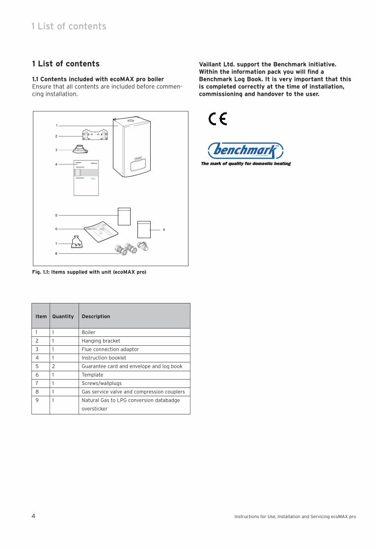
1.1 Contents included with ecoMAX pro boilerEnsure that all contents are included before commen-cing installation.
Fig. 1.1: Items supplied with unit (ecoMAX pro)
1
2
3
4
5
6
7
8
9
Item Quantity Description
1 1 Boiler
2 1 Hanging bracket
3 1 Flue connection adaptor
4 1 Instruction booklet
5 2 Guarantee card and envelope and log book
6 1 Template
7 1 Screws/wallplugs
8 1 Gas service valve and compression couplers
9 1 Natural Gas to LPG conversion databadge
oversticker
Vaillant Ltd. support the Benchmark initiative.Within the information pack you will find aBenchmark Log Book. It is very important that thisis completed correctly at the time of installation,commissioning and handover to the user.

Important information 2
Instructions for Use, Installation and Servicing ecoMAX pro 5
2 Introduction
2.1 General InformationThank you for choosing a Vaillant boiler. The informationgiven in this booklet will enable you to obtain the bestperformance from your boiler.The Benchmark logbook should be completed by theinstaller and/or commissioning engineer and handed tothe user.
Note!This boiler must be installed and serviced by acompetent person in accordance with the GasSafety (Installation and Use) Regulations 1998.In the UK 'CORGI' registered installers underta-ke the work to a safe and satisfactory standard.
This boiler is designed to provide central heating from afully pumped open-vented or sealed water system with afully indirect cylinder. The central heating water temperature can be adjustedon the boiler.Once the controls are set the boiler operates automati-cally.A frost protection programme is also included.Please read these instructions and follow them carefullyfor the correct and economical use of your boiler.
2.2 Gas CategoryThis boiler is factory set for use on Natural Gas (G20).ecoMAX pro 28E only can be field adjusted for use onLPG (propane G31), see page 22-23 for instructions.
2.3 Gas Safety (Installation and Use) RegulationsIn your own interests and that of safety, it is the Lawthat ALL gas appliances are installed by a competentperson in accordance with the current issue of theabove regulations.
2.4 Gas Testing and CertificationThe boiler is tested and certificated for safety and per-formance. It is, therefore, important that no alteration ismade to the boiler.
2.5 CE MarkThis boiler meets the requirements of StatutoryInstrument, No. 3083 The Boiler (Efficiency)Regulations, and therefore is deemed to meet the requi-rements of Directive 92/42/EEC on the efficiency requi-rements for new hot water boilers fired with liquid orgaseous fuels.Type test for purposes of Regulation 5 certified by:Notified body 0086.Product/production certified by: Notified body 0086.The CE mark on this appliance shows compliance with:
1. Directive 90/396/EEC on the approximation of thelaws of the Member States relating to appliances bur-ning gaseous fuels.2. Directive 73/23/EEC on the harmonisation of the Lawsof the Member States relating to electrical equipmentdesigned for use within certain voltage limits.3. Directive 89/336/EEC on the approximation of theLaws of the Member States relating to electromagneticcompatibility.
2.6 Control of Substances Hazardous to HealthUnder Section 6 of The Health and Safety at Work Act1974, we are required to provide information on substances hazardous to health.The adhesives and sealants used in this appliance arecured and give no known hazard in this state.
2.6.1 Insulation PadsThese can cause irritation to skin, eyes and the respiratory tract.If you have a history of skin complaint you may be sus-ceptible to irritation. High dust levels are usual only ifthe material is broken.Normal handling should not cause discomfort, but follownormal good hygiene and wash your hands beforeeating, drinking or going to the lavatory.If you do suffer irritation to the eyes or severe irritationto the skin seek medical attention.
2.7 Spare PartsOnly original Vaillant spare parts may be used.
2.8 Manual Handling GuidanceDuring the appliance installation and the replacement ofthe heat exchanger it will be necessary to employ caution and assistance whilst lifting as the appliance orcomponent exceeds the recommended weight for a oneman lift.In certain situations it may be required to use a mechanical handling aid.Take care to avoid trip hazards, slippery or wet surfaces.
2.9 WarningsGas Leak or FaultIf a gas leak or fault exists or is suspected, turn the boiler mains electrical supply off and turn off the gassupply at the meter. Consult your local gas company oryour local installation/servicing company.
ClearancesIf fixtures are positioned close to the boiler, space mustbe left as shown in Fig. 6.1. Enough space must also beleft in front of the boiler to allow for servicing.

2 Important information
2.12 Boiler Casing Do not remove or adjust the casing in any way, as incorrect fitting may result in incorrect operation or failure to operate at all.
2.13 Condensate DrainThe condensate drain, see section 10.3, must not bemodified or blocked.
2.14 Pluming from flue terminalAll condensing boilers produce a plume of water vapourfrom the flue terminal. This is due to the high efficiencyand hence low flue gas temperature. This may increasein wet, damp weather but this is completely normal andindicates that the boiler is operating correctly.
2.15 CleaningThis appliance contains metal parts and care should betaken when handling and cleaning with particular regardto edges. The boiler casing can be cleaned using a mild liquiddetergent with a damp cloth, then a dry cloth to polish.Do not use any form of abrasive or solvent cleaner asyou may damage the paintwork.
2.16 Maintenance and ServicingFor the continued efficient and safe operation of the boiler it is recommended that it is checked and servicedat regular intervals. The frequency of servicing willdepend upon the installation conditions and usage, butin general, once a year should be enough.If this appliance is installed in a rented property there isa duty of care imposed on the owner of the property bythe current issue of the Gas Safety (Installation and Use)Regulations, Section 35.Servicing/maintenance should be carried out by a competent person in accordance with the rules in forcein the countries of destination.To obtain service, please call your installer or VaillantService Solutions (0870 6060 777).Please be advised that the installation engineer on com-pletion of commissioning and servicing should completethe ‘Benchmark’ logbook.All CORGI Registered Installers carry a CORGI ID card,and have a registration number. Both should be recor-ded in your boiler Logbook. You can check your installeris CORGI registered by calling CORGI direct on: - 01256372300.
Instructions for Use, Installation and Servicing ecoMAX pro6
Sheet Metal PartsThis boiler contains metal parts (components) and careshould be taken when handling and cleaning, with particular regard to edges.
Sealed ComponentsUnder no circumstances must the User interfere withany sealed component as this could result in a potentially dangerous situation arising.
Electrical Supply FailureThis boiler must be earthed.The boiler will not work without an electrical supply.Normal operation of the boiler should resume when theelectrical supply is restored.Reset any external controls to resume normal operationof the central heating.If the boiler does not resume normal operation turn themains reset switch off and on. If the boiler does notresume normal operation after this the overheat thermostat may have operated. The overheat thermostat would only operate under abnormal conditions and, under these circumstances; it would beadvisable to consult your installation / servicing company.
2.10 Protection Against FreezingThe boiler has a built in frost protection programme aslong as the electricity and gas are left switched on.This device operates the burner and system pump whenthe temperature inside the boiler falls to 3 °C.Any other exposed areas of the system should be protected by a separate frost thermostat.If the mains electricity and gas are to be turned off forany long periods during severe weather, it is recommended that the whole system, including the boiler, should be drained to avoid the risk of freezing.Make sure that, if fitted, the immersion heater in thecylinder is switched off. If you have a sealed water system contact your installation/ servicing company as draining, refilling andpressurising MUST be carried out by a competent person.As a safety feature the boiler will stop working if thecondensate drain becomes blocked. During freezing conditions this may be due to the forming of ice in thecondense drain external to the house. Release an iceblockage by the use of warm cloths on the pipe. The boiler should then restart. Contact your installation/servicing company if the fault persists.
2.11 Boilers Installed in a Compartment or CupboardIf the boiler is fitted into a compartment or cupboard itdoes not require ventilation openings.Do not use the compartment or cupboard for storage.

2 Important information Operating the boiler 3
Instructions for Use, Installation and Servicing ecoMAX pro 7
3.3 User Controls Slide the On / Off control down to the I position to turnon the boiler. The operating indicator will illuminate(green) to show that the boiler is on.
The temperature of the central heating water can beadjusted by pushing the mode button ( ) until theradiator symbol is displayed. Pushing the + or - buttonswill then set the water temperature as desired. (Typicalsetting temperatures for a normal radiator heatingsytem will be in the range of 60 °C to 80 °C. Note thatset temperatures below 60 °C will not sufficiently heatany hot water cylinder). To return to the normal modepush the mode button ( ) until the display shows thecurrent temperature of water in the boiler.When the boiler is operating the flame symbol will beshown in the display. The bar symbol is also shown andthis indicates the modulating output of the boiler. Theboiler will automatically modulate to the output neededby the heating system - the more bars that are display-ed, the higher the output.The ecoMAX pro is a fan flue appliance and the operati-on of the fan may be heard when the boiler is runningand for a short period after the boiler has stopped.Should a fault condition occur the operating indicatorwill flash red and will be accompanied by an "F" symbolin the display. To reset the boiler slide the On / Off con-trol to the Off (O) position and after 5 seconds back tothe On (I) position. The boiler should now operate. If thefault persists contact your installer / service provider.The ecoMAX pro has a Holiday / frost mode. If you aregoing on holiday and do not want the boiler to be opera-ted by the external heating controls press the mode but-ton ( ) until the MODE indicator flashes in the lefthand edge of the display. Then press the + or - buttonuntil the arrow indicator points to the holiday symbol( ). The boiler will now only operate if necessary forfrost protection of the boiler itself as well as running adaily pump exercise programme to prevent sticking. Itwill not be turned on and off by the external heatingcontrols. If a system frost protection thermostat hasbeen fitted this will remain active.
3.4 To Turn the Boiler OffNormally the boiler will be turned off by the heatingsystem controls. The mains On / Off control may be usedto switch off the boiler, however it is preferable to leavethe electrical supply on whenever possible to permitoperation of the built-in frost protection and daily pumpexercise programme.
Fig. 3.1
2.17 GuaranteeOur confidence in the quality of craftmanship and performance of our products is demonstrated by theVaillant two year guarantee.During the first year from installation the guaranteecovers your boiler against manufacturing defects forboth parts and labour. In order to extend this guaranteeto the second year from installation all you have to do isensure that your boiler receives a service when it is ayear old. (Please note that the cost of the service is notincluded in the guarantee). Should your boiler develop a fault please contact youroriginal installer or alternatively contact Vaillant ServiceSolutions on 0870 6060 777.IMPORTANT...to qualify for your two year guarantee:Please complete the registration details on the guarantee card and return in the pre-paid envelope to:Vaillant Registration DepartmentFreepost CV 2560BEDWORTHWarwickshireCV12 8BRThe registration card must be returned within 30 days ofthe boiler being installed.The boiler must be serviced either by Vaillant Ltd. oranother competent servicing company (CORGI registered) within one year of the installation date andthe details recorded in the "Installation, Commissioningand Service Record Log Book" (this log book shouldhave been completed and left with you by your installer).Please note that the cost of the service is not includedin the guarantee.Vaillant is a member of the Benchmark initiative andfully supports the aims of the programme. Benchmarkhas been introduced to improve the standards of instal-lation and commissioning of central heating systems inthe UK and to encourage the regular servicing of all cen-tral heating systems to ensure safety and efficiency.
3 Operating the Boiler
3.1 Sealed Central Heating Systems onlyCAUTION. A sealed water system must be filled andpressurised by a competent person.Only light the boiler when you are sure that the systemand boiler have been filled and pressurised.The pressure should read at least 0.7 bar, when thesystem is cold. If the needle displays a value below this,follow the instructions left by your installer to refill thesystem. Alternatively your installer should be called torefill the system.
3.2 All SystemsCheck that the electrical supply to the boiler is ON atthe external isolator.Set any remote heating system controls as required.

4 General Information
Instructions for Use, Installation and Servicing ecoMAX pro8
4 General Information
Important noticeThe boiler is supplied in one pack and the flue is supplied separately.This boiler is factory set for use on Natural Gas (G20),ecoMAX pro 28E only can be field adjusted for use onLPG (propane G31).Where no British Standards exists, materials and equipment should be fit for their purpose and of suitablequality and workmanship.Refer to Manual Handling Operations, 1992 regulations.The installation of this boiler must be carried out by acompetent person in accordance the rules in force in thecountries of destination.Manufacturer’s instructions must not be taken as overriding statutory requirements.
4.1 Sheet Metal Parts
Warning!When installing the appliance, care should betaken to avoid any possibility of personal injurywhen handling sheet metal parts.
4.2 Statutory RequirementsThe installation of the boiler MUST be carried out by acompetent person in accordance with the relevant requirements of the current issue of: Manufacturer's instructions supplied.The Gas Safety (Installation and Use) Regulations, TheBuilding Regulations, The Building Regulations(Scotland), The Building Regulations (Northern Ireland),Water Supply (Water Fittings) Regulations, Water Bylaws,The Health and Safety at Work Act, Control ofSubstances Hazardous to Health, The Electricity at WorkRegulations, the current IEE wiring regulations and anyapplicable local regulations. Detailed recommendations are contained in the currentissue of the following British Standards and Codes ofPractice, BS4814, BS5440 Part 1 and 2, BS5449,BS5546, BS6700, BS6798, BS6891 and BS7074 Part 1and 2, BS7478, BS7593, BS7671.In IE the installation must be carried out in accordancewith the current edition of IS 813 'Domestic GasInstallations', the current Building Regulations and refe-rence should be made to the current ETCI rules for elec-trical installation.
4.3 Gas SupplyThe gas installation must be in accordance with the current issue of BS6891. In IE this is the current editionof IS813.The supply from the governed meter must be of adequate size to provide a steady inlet working pressureof 20mbar (8in wg) at the boiler.
On completion, test the gas installation for soundnessusing the pressure drop method and suitable leak detection fluid, purge in accordance with the above standard.
4.4 Technical DataAll dimensions are given in millimetres (except asnoted). See Fig. 4.1.The data label is positioned on the combustion chambercover see fig. 4.2.The data label includes the product Gas Council number;18E - 41 044 3028E - 41 044 31
Fig. 4.1
Fig. 4.2
150

4 General Information Water system 5
Instructions for Use, Installation and Servicing ecoMAX pro 9
4.5 Electrical SupplyThe boiler must be earthed.All system components shall be of an approved type andall wiring to current I.E.E. wiring regulations. In IE refe-rence should be made to the current edition of the ETCIrules.The boiler must be connected to a permanent 230 V ac,50 Hz supply.Connection of the whole electrical system of the boiler,including any heating controls, to the electrical supplymust be through one common isolator and must befused 3 Amp maximum. Isolation should be by a doublepole switched fused spur box, with a minimum gap of3mm for both poles. The fused spur boxshould be readily accessible and preferably adjacent tothe appliance. It should be identified as to its use.Alternatively connection can be made through an uns-witched shuttered socket and 3A fused 3-pin plug bothto the current issue of BS 1363 may be used, providedthey are not used in a room containing a bath or shower.The colours of three core flexible cable are, blue - neutral, brown - live, green and yellow - earth.
4.6 Condensate DrainA plastic drain pipe must be fitted to allow discharge ofcondensate to a drain.Condensate should, if possible, be discharged into theinternal household draining system. If this is not practical, discharge can be made externally into the hou-sehold drainage system or a purpose designed soakaway, see Section 10.3 for more details.
4.7 Heating System ControlsIt is recommended that a programmer and room ther-mostat control the boiler.Thermostatic radiator valves may be installed, howeverthey must not be fitted in a room where the room ther-mostat is located.
Note!All systems must have at least one radiator notfitted with a thermostatic valve.
Note!For further information, see the current issue ofthe Building Regulations, approved document L1,and the references:
1) GIL 59, 2002: Central heating system specification(CheSS)
and 2) GPG 302, 2001: Controls for domestic central heatingsystem and hot water. BRECSU.
5 Water system
5.1 Draining TapA draining tap must be provided at the lowest point ofthe system, which will allow the entire system and hotwater system to be drained.Draining taps shall be to the current issue of BS 2879.
5.2 Safety ValveA safety valve need not be fitted to an open-ventedsystem. See also section 5.9.1.
Fig. 5.1
Fig. 5.2
28 E Pressure Loss Graph
Flow Rate (litres/hour)
1289 l/hr = 20 diff @ 28kW
Wat
er
Pre
ssu
re L
oss
(m
etr
es
he
ad o
f w
ate
r)
0.00
0.50
1.00
1.50
2.00
2.50
3.00
200 400 600 800 1000 1200 1400
2.55 m
0
0.5
1
1.5
2
2.5
0 100 200 300 400 500 600 700 800 900 1000
18 E Pressure Loss Graph
Flow Rate (litres/hour)
773.86 l/hr = 20 diff @ 18 kW
Wat
er
Pre
ssu
re L
oss
(m
etr
es
he
ad o
f w
ate
r)1.38m

Water system 5
Instructions for Use, Installation and Servicing ecoMAX pro10
5.5 InhibitorAttention is drawn to the current issue of BS 5449 andBS 7593 on the use of inhibitors in central heatingsystems.If an existing system is to be reused take special care todrain the entire system, including the radiators, thenthoroughly cleaning out before fitting the boiler whetheror not adding an inhibitor.For advice please refer to 5.10, Water Treatment.
5.6 Open (Vented) Water SystemThe boiler must be supplied from an unrestricted watersupply taken from a feed and expansion cistern situatedat a maximum height of 27 metres (90ft) above the boiler.The cold feed must be 15mm minimum size.The vent must rise continuously and be unrestricted.It is important that the relative positions of the pump,cold feed and open vent are as shown in Fig. 5.3.
5.7 Domestic Hot Water Cylinder
Warning!Single feed indirect cylinders are not suitable.
The domestic hot water cylinder must be of the doublefeed fully indirect coil type.
5.8 Domestic Hot Water System - unventedWhere a storage system will not have a vent to atmosphere the installation must comply with theBuilding Regulations and local Water Company bylaws,see also the current issue of BS5546 and BS6700. In IEthe requirements given in the current edition of IS 813and the current Building Regulations must be followed.If fitting to an existing system the local authority shouldbe informed.
Note!ecoMAX pro boilers are not suitable for use withVaillant VANTAGE unvented cylinders and MUSTnot be used in connection with these cylinders.
Fig. 5.3
Table 5.1 Flow rate
5.3 PumpThe pump should be fitted on the flow pipe from the boiler and have isolating valves each side.A variable duty pump should be set to give a temperature difference of no greater than 20 °C between the flow and return, with the thermostat set at“MAX”, which is about 80 °C, to give a flow rate asshown in table 5.1.See chart for pressure loss of the boiler, Fig. 5.1 or 5.2.High resistance microbore systems may require a higherduty pump.
5.4 BypassA bypass is not required on the central heating systemunless all radiators are fitted with thermostatic radiatorvalves or the system controls could allow the boiler andpump to operate when there is no flow. Where a bypass has to be fitted, the bypass must be pla-ced at least 1.5 metres away from the boiler.
Open (vented) system.Recommendedrelationship betweenpump, cold feed and vent.
22mm (MIN.) VENTFEED ANDEXPANSION CISTERN
15mm (MIN) COLD FEED
15mm (MIN.) BY-PASS(if required)
RE
TU
RN F
LO
W
HE
AT
ING
CY
LIN
DE
R
PUMP
BOILER 150mm MAX.
1000mmMIN.
450mmMIN.HEIGHT
Model Minimum flow rate
ecoMAX pro 18 E 773.8 litres/hr
ecoMAX pro 28 E 1289 litres/hr
This is equal to 20 °C differential at maximum heat input.

Water system 5
Instructions for Use, Installation and Servicing ecoMAX pro 11
5.9.3 Pressure GaugeA pressure gauge with a set pointer and covering atleast 0 to 4 bar (0 to 60 lb/in2) shall be fitted perma-nently to the system in a position where it can be seenwhen filling the system.
5.9.4 Domestic Hot Water CylinderThe domestic hot water cylinder must be of the doublefeed fully indirect coil type. It must be suitable for working at a gauge pressure of 0.35 bar above thesafety valve setting.
5.9.5 Water MakeupProvision should be made for replacing water loss fromthe system using a make up bottle mounted in a positionhigher than the top point of the system, connectedthrough a non-return valve to the return side of eitherthe heating circuit or the hot water cylinder.Alternatively, provision for make up water should bemade using a proprietary filling loop.
5.9.6 Filling a Sealed Water SystemProvision for filling the system at low level must bemade. This can be achieved by the use of a proprietaryfilling loop.
5.10 Water TreatmentFor optimum performance the boiler and its associatedcentral heating system should be flushed in accordancewith BS7593: 1992 using a cleanser.For advice on the application of system cleansers andinhibitors contact either;Fernox, Alpha-Fry TechnologiesTandem HouseMarlow WayBeddington Farm RoadCroydon CR0 4XSTel: 0870 601 5000Fernox technical help line01799 550811or:Sentinel, GE BetzWidnesCheshire, WA8 8UDTel: 0151 420 9595
5.9 Sealed water SystemsThe installation must comply with the appropriate requirements of the current issue of BS4814, BS5449,BS6759, BS6798 and BS7074 Part 1 and 2. For IE yourattention is drawn to the current edition of IS 813.See Fig. 5.4 for a suggested layout.
Fig. 5.4
5.9.1 Safety ValveA safety valve must be fitted to a sealed system.It shall be preset, non-adjustable with a lift pressure of3 bar, incorporating seating of a resilient material, a testdevice and a connection for drain.The safety valve discharge pipe must be routed to outside the building, must not discharge above an entrance or window or any type of public access area, beclear of any electrical fittings and positioned so that anydischarge can be seen.
5.9.2 Expansion VesselA diaphragm type expansion vessel, conforming to thecurrent issue of BS4814 (see also BS7074 Part 1 and 2).For IE the current edition of IS 813, must be connectedat a point close to the inlet side of the circulating pump,see the diagrammatic layout, Fig. 5.4. unless laid downdifferently by the manufacturer.The expansion vessel volume depends on the total watersystem volume and the initial system design pressure.For any system an accurate calculation of vessel size isgiven in the current issue of BS5449 and BS7074 Part 1.Example: For an initial design pressure of 0.7 bar, theminimum total vessel volume required is 0.063 x TotalSystem Volume.
Note! A higher initial design pressure requires a largervolume expansion vessel.
The charge pressure must not be less than the static head of the system, that is, the height of the highest point of the system above the expansion vessel.
3 LITRES (0.66 gals)MAKE-UP BOTTLE(if required)
NON-RETURNVALVE
AUTOAIRVENT
FLOW
DRAINCOCK
BOILER
SAFETYVALVE
(Make-upalternatives)
EXPANSIONVESSEL
PRESSUREGAUGE
CIRCULATINGPUMP
FILLING POINT
AIRRELEASEPOINT
HE
AT
ING
CIR
CU
IT
BY-PASS 'B' IF REQUIRED
FLOWCONTROL VALVE 'A'
FLOWCONTROL VALVE 'A'

6 Boiler Location and Ventilation
Instructions for Use, Installation and Servicing ecoMAX pro12
Fig. 6.1
*
* *
*Increase to 25mm clearance fromcombustible material.
†
MINIMUM CLEARANCE FROMPERMANENT SURFACES
† A removable compartment door can beplaced at least 5mm in front of the appliance.
55
600
200**
20 20
200
** 220mm above the boiler when utilising the 125mm flue system
5
6 Boiler Location and Ventilation
6.1 Boiler LocationThe boiler may be installed in any room although particular attention is drawn to the requirements of thecurrent issue of BS7671, IEE Wiring Regulations, theelectrical provisions of the Building Regulations(Scotland), and in IE the current edition of IS 813 andthe ETCI rules, with respect to the installation of a boilerin a room containing a bath or a shower. Any electricalswitch or boiler control using mains electricity should beso situated that a person using the bath or shower can-not touch it.The boiler must be mounted on a flat wall, which is sufficiently robust to take its total weight. The boilermay be installed on a combustible wall, subject to therequirements of the Local Authorities and BuildingRegulations.The boiler is not suitable for fitting outdoors.
6.2 ClearancesThe boiler should be positioned so that at least the minimum operational and servicing clearances are provided, see Fig. 6.1.Additional clearances may be beneficial around the boiler for installation and servicing.For flue installations where external access is not practicable, consideration should be given for the spacerequired to insert the flue internally, which may necessitate clearance larger than those specified in Fig. 6.1.
6.3 Timber Frame BuildingsIf the boiler is to be installed in a timber frame buildingit should be fitted in accordance with the Institute of GasEngineers document IGE/UP/7/1998.
6.4 Room VentilationThe boiler is room sealed, so when it is installed in aroom or space, a permanent air vent is not required.
6.5 Compartment VentilationIf the boiler is installed in a compartment, a permanentair vent is not required.Leave existing air vents.

Flue 7
Instructions for Use, Installation and Servicing ecoMAX pro 13
7.2 Flue terminationThe following details refer to both flue systems.a. The terminal must be positioned such that the pro-
ducts of combustion can disperse freely at all times.b. In certain weather conditions a plume of water
vapour may be visible from the flue terminal.Positions where this could be a nuisance should beavoided.
c. If the terminal is fitted less than 2 m above a bal-cony, above ground or above a flat roof to which peo-ple have access then a suitable terminal guard mustbe provided and fitted (A suitable guard is manufac-tured by: Tower Flue Components, Morley Road,Tonbridge, Kent, TN9 1RA. Size: 280mm x 280mm x270mm) reference code K6.
Note!Vertical flues must not terminate within600 mm of an openable window, air vent or anyother ventilation opening.
The flue assembly shall be so placed or shielded as toprevent ignition or damage to any part of the building.
Fig. 7.3
A
BCD
A
G
H, IF J
B F M
L
LK
K
G
G
F F
E
AA
7 Flue
7.1 Flue Position and LengthThe standard horizontal flue is fitted onto the top of theboiler.See Fig. 7.1 and 7.2 to determine whether a standard fluecan be used.
Fig. 7.1
Fig. 7.2
Flue systemThe standard 100mm flue system (Art. No. 303 930) issuitable for installations up to 730 mm measured from the centre of the boiler flue outlet to the outside face of the wall.Flue extensions are available to extend this length up to 10 m (see section 11.2). Both 90° bends and 45° elbowsare also available to increase siting flexibility.A concentric flue system of 125 mm outside diameter is available and can be used to achieve flue lengths up to 20 m.A vertical flue system is also available.Refer to flue system installation instructions for fulldetails.When extension pipes are used the flue system must be designed to have a continuous fall to the boiler of atleast 3° to allow condensate to run out via the drain.
SIDE FLUE - STANDARD
DISTANCE 'Y' = 345 TO 730mm - LeftDISTANCE 'Y' = 250 TO 730mm - Right
"Y"
WALL THICKNESS 'X' = 75 TO 550 mm
REAR FLUE - STANDARD
"X"
7 Flue Installation Preparation 8
Instructions for Use, Installation and Servicing ecoMAX pro14
1) In addition, the terminal should not be nearer than 150mm to anopening in the building fabric formed for the purpose ofaccommodating a built-in element such as a window.
2) Dimension B,C and D; These clearances may be reduced to 25 mm without affecting the performance of the boiler. In orderto ensure that the condensate plume does not affect adjacentsurfaces the terminal should be extended as shown in Fig 7.4.
3) Dimension F; This clearance may be reduced to 25 mm withoutaffecting the performance of the boiler. However, in order toensure that the condensate plume does not affect adjacent surfa-ces a clearance of 300 mm is preferred.
4) BS 5440-1 It is recommended that a fanned flue terminal shouldbe positioned as follows:
a) at least 2m from an opening in a building directly opposite, and b) so that the products of combustion are not directly directed to
discharge across a boundary. For IE, recommendations are givenin the current edition of IS 813.
Fig. 7.4
7.3 Internal Flue InstallationThe flue can be installed from inside the building whenaccess to the outside wall face is not practicable.
7.4 Flue OptionsThere are various flue systems to choose from, as follows:
balcony/eaves
flue extended toclear any overhang
flue adequatelysupported
gutter
• Vertical air/flue duct and terminal 303 900• Air/flue duct extension (470 mm) 303 902• Air/flue duct extension (970 mm) 303 903• Air/flue duct extension (1970 mm) 303 905• Telescopic air/flue duct extension
(440 mm - 690 mm) 303 906• 87° elbow 303 910• Two 45° bends 303 911• Standard horizontal air/flue duct
with elbow and terminal (800 mm) 303 930Additional accessories are available.
8 Installation Preparation
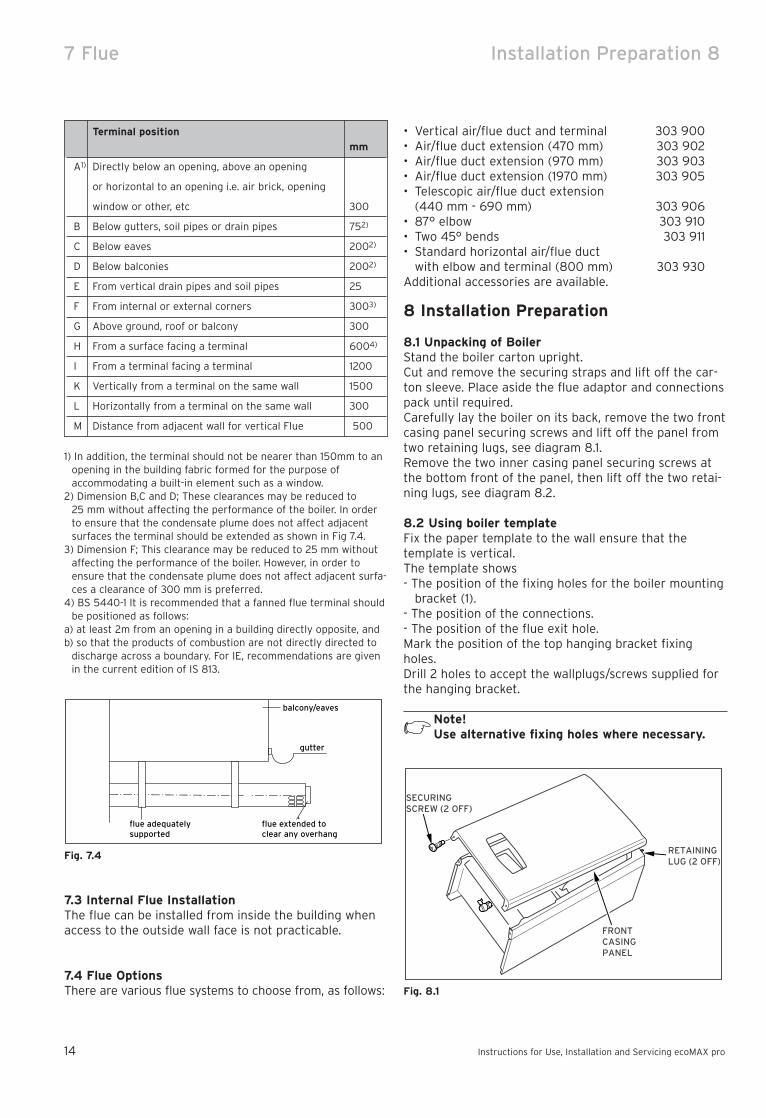
8.1 Unpacking of BoilerStand the boiler carton upright.Cut and remove the securing straps and lift off the car-ton sleeve. Place aside the flue adaptor and connectionspack until required.Carefully lay the boiler on its back, remove the two frontcasing panel securing screws and lift off the panel fromtwo retaining lugs, see diagram 8.1.Remove the two inner casing panel securing screws atthe bottom front of the panel, then lift off the two retai-ning lugs, see diagram 8.2.
8.2 Using boiler templateFix the paper template to the wall ensure that thetemplate is vertical.The template shows- The position of the fixing holes for the boiler mounting
bracket (1).- The position of the connections.- The position of the flue exit hole.Mark the position of the top hanging bracket fixingholes.Drill 2 holes to accept the wallplugs/screws supplied forthe hanging bracket.
Note!Use alternative fixing holes where necessary.
Fig. 8.1
SECURINGSCREW (2 OFF)
FRONTCASINGPANEL
RETAININGLUG (2 OFF)
Terminal position
mm
A1) Directly below an opening, above an opening
or horizontal to an opening i.e. air brick, opening
window or other, etc 300
B Below gutters, soil pipes or drain pipes 752)
C Below eaves 2002)
D Below balconies 2002)
E From vertical drain pipes and soil pipes 25
F From internal or external corners 3003)
G Above ground, roof or balcony 300
H From a surface facing a terminal 6004)
I From a terminal facing a terminal 1200
K Vertically from a terminal on the same wall 1500
L Horizontally from a terminal on the same wall 300
M Distance from adjacent wall for vertical Flue 500

8 Installation Preparation Boiler fixing 9
Instructions for Use, Installation and Servicing ecoMAX pro 15
Fig. 8.3
To allow for the flue passing through the wall at thisangle a 127 mm hole should be drilled irrespective ofinternal or external installation.If necessary remove the template whilst drilling the fluehole.
9 Boiler fixing
9.1 Fitting the boiler hanging bracketFix the hanging bracket to the wall using the screws sup-plied. Ensure the uppermost set of screw positions areused (it may be necessary to use additional or alternative fixings to ensure adequate support).
Note!If the boiler is to be fitted in a timber framedbuilding ensure that the bracket is secured to asubstantial part of the timber frame capable oftaking the weight of the boiler.
9.2 Boiler FixingHaving previously secured the hanging bracket to thewall, lift the boiler into position in the following manner: Lean the top of the boiler slightly to the wall and position just above the hanging bracket. Allow the boilerto slowly move downwards until engaged in the hangingbracket.
Fig. 9.1
WALL PLUG(4 OFF)
SCREW N o12 x 50mm(4 OFF)
WALLTEMPLATE
HANGINGBRACKET
WALLTEMPLATE
Ø 127
900
1763°±1°
Fig. 8.2
8.3 Rear flue exitMark the position of the air/flue duct and its circumference.
8.4 Other flue optionsFlue instructions for other flue systems such as verticalRSF flues, flues run to the side of the boiler and the useof additional bends etc. are detailed in the flue installation instructions.Remove the template from the wall and plug the drilledholes using the wallplugs supplied.
8.5 Flue Hole CuttingThe standard horizontal flue is designed with an internalfall of 50 mm (± 20 mm) /metre towards the boiler fordisposal of condensate.If the standard flue length alone is being used then theflue hole can be cut in the position marked on the walltemplate.For installations with external access, a 107 mm diame-ter core drill can be used.For installations with internal access only, a 127 mm dia-meter core drill should be used.For extended side flues, the flue hole centre should bedetermined by extending the dashed incline line on thetemplate to the side wall. This dashed line is drawn at a50 mm/metre (3°) rise from the boiler. Where this linereaches the side wall, a horizontal line should be mar-ked. The vertical centre line of the flue should then bemarked at 176 mm from the back wall, see Fig. 8.3.
INNERCASINGPANEL
RETAININGLUGS

10 Gas, Water and Condensate Connections
Instructions for Use, Installation and Servicing ecoMAX pro16
10 Gas, Water and CondensateConnections
10.1 Gas ConnectionBefore connection check the supply of local gas.The gas supply can be connected from below, or throughthe wall at the rear of the boiler.Ensure the supply pipe is fully engaged in the compres-sion fitting on the gas service valve inlet. See Fig. 10.1.and refer to section 4.3.
Fig. 10.1
10.2 Water ConnectionsProvision is made for the water connections to be madefrom above the boiler, see Fig. 10.2 (using the two 22mmcompression couplers supplied). The position is shownon the wall template.Flush out the domestic hot water and the heatingsystems before connecting to the boiler.
Fig. 10.2
FLOW
RETURN
PLASTICOVERFLOWPIPE
GASSERVICECOCK
GASSUPPLYPIPE IN
GAS SERVICECOCK SHOWN INOPEN POSITION
UNION CONNECTOR
CAP
GAS SERVICECOCK LINER
SPIGOT
CONDENSATE DRAINCONNECTION
10.3 Condensate Drain ConnectionThe condensate drain connection is at the rear of theboiler, see Fig. 10.1. A 21.5 mm plastic overflow pipeshould be connected to the spigot on the condense trap(using the coupler). The drain pipe should have a fall ofa least 2.5° away from the boiler. Condensate should, ifpossible be discharged into the household internal drai-nage system. If this is not practicable, discharge can beallowed into the external household drains or a purposedesigned soak away. It is recommended that any external condensate drain
pipe is insulated and also preferably of 32mm diameter,to prevent freezing in adverse weather conditions.The condensate is discharged periodically in ‘slugs’ bysiphonic action.It is not necessary to provide air breaks or extra traps inthe discharge pipe, as there is already a 75mm high trapinside the boiler. Fitting an extra trap may cause theboiler siphon to work incorrectly. Refer to BS 6798 andBS 5546 for advice on the disposal of the boiler con-densate.

Flue Preparation and Installation 11
Instructions for Use, Installation and Servicing ecoMAX pro 17
11.2 Extension pipesRefer to Figs. 11.3 and 11.4.Note maximum permitted flue lengths.When extension pipes are required please note thelength of the extensions, which should be taken intoaccount when calculating the length that requires cut-ting.For example:Distance from outside wall to butt joint on the flueelbow ‘Y’ = 1500 mm.Standard flue length = 633 mm.Extension pipe length = 970 mm.Length of extension pipe air duct = 1500 - 633 = 867mm.In this example the extension pipe would be cut to867 mm, this would be measured from the end of the airduct where the flue duct contains the ‘o-ring’ seal.When cutting, the flue duct should be cut to protrude13 mm from the end of the air duct at the opposite endto where the flue duct contains the ‘o-ring’ seal.The maximum permitted straight flue length is 10 metres. For each 90° elbow or pair of 45° bends fit-ted, the maximum length must be reduced by 1 metre.
Note!When using elbows/bends any horizontal exten-sion pipe should be inclined by 3° ± 1° falltowards the boiler to facilitate condense remo-val.
Fig. 11.3 Side flue extension
DRILLANDSCREW
Side of boiler
107
127
11 Flue Preparation and Installation
11.1 Flue LengthAll dimensions are in mm.To determine flue length, temporarily fit flue elbow totop of boiler.For rear or side flue, measure the distance from the outside wall to the butt joint of the flue elbow fitted ontop of the boiler. A standard flue system will be suitableif the length measured ‘Y’ is less than 633 mm, see Figs. 11.1 and 11.2.If the measurement ‘Y’ exceeds 633 mm then one ormore extension pipes are required.When cutting, the flue duct should protrude 13 mm fromthe end of the air duct.
Fig. 11.1 Rear flue
Fig. 11.2 Standard side flue
OUTER RUBBER COLLAR
Internaltrim ring
Y
70
OUTSIDEWALLFACE
DRILL ANDSCREW
BOILERMOUNTINGWALL
150

11 Flue Preparation and Installation
Instructions for Use, Installation and Servicing ecoMAX pro18
11.4 Flue Attachment To BoilerLubricate the internal rubber seal of the flue outlet onthe boiler with a suitable lubricant. Push and twist theflue adapter into position on top of the boiler and securewith the four screws supplied, making sure the nib fitsinto the locating slot in the boiler casing to ensure cor-rect orientation. Fit the flue elbow with the securing collar (length40 mm) on to the flue adapter.Secure the flue elbow by tightening the two screws onthe securing collar.Draw flue assembly from wall, fit securing collar (length70 mm), slide flue duct into flue elbow.
Note!If the air and flue ducts have been correctly cutto the instructions given in sections 11.1-11.2 therubber sealing collar should fit flush with theoutside wall.
Position securing collar centrally over joint, tightensecuring screws. Drill and insert four self-tapping screws, supplied, in the holes provided in the securingcollar.Secure internal trim ring in position with a small amountof sealant.
Fig. 11.4 Elevated horizontal flue
11.3 Flue AssemblyThe flue assembly is a push fit design with securingcollars.Remove all burrs from cut pipes.Fig. 11.5 shows the components supplied in the standardkit and the flue adapter.Having cut the air and flue ducts as described in sections 11.1- 11.2 assemble the flue as follows, the fluecan be fitted externally or internally.Fit the rubber sealing collar behind the locating lugs onthe flue terminal, see diagram 11.5. Push the flue assembly into the wall, externally or internally, initiallyuntil the end of the assembly protrudes a short wayfrom the inside face of the wall. This will enable theinternal square trim ring to be positioned and allow theflue duct to be drawn into the flue elbow after the flueadapter has been fitted.
Fig. 11.5
FLUEELBOW
FLUEADAPTER
SECURINGCOLLAR(40mm)
SECURINGCOLLAR (70mm)
INTERNAL TRIM
AIRDUCT
FLUEDUCT
SEALINGCOLLAR
FLUETERMINAL
RING
EXTENDED HORIZONTAL FLUE
X + Y must not exceed10 metres plus standardhorizontal flue kit.
Reduce flue length by1 metre for everyadditional 90° or pair of 45° bends.
X
Y
Total flue length must not exceed 10metres plus standard horizontal flue kit
Reduce flue length by 1 metre for everyadditional 90° or pair of 45° bends.

Electrical Connections 12
Instructions for Use, Installation and Servicing ecoMAX pro 19
Disconnect and remove the test cable from the terminalstrip and discard.
Connect both the mains supply and switched live fromthe external controls (room thermostat and, if applica-ble, frost thermostat) into the marked terminals asshown in Figs. 12.2 and 15.1.
Fig 12.2
Connect the pump supply into the marked pump termi-nals as shown in Figs.12.2 and 15.1.
(Note: the boiler incorporates a pump overun thermost-at. Only feed the pump from the marked terminals in theterminal box on the boiler, not from a separate supply).
Observe all terminal markings and colour codes shownin Fig. 15.1.
Ensure that all flexible cords are routed through thestrain relief cable glands on the inlet of the terminal box.
Refit the terminal box to the underside of the boilerusing the two retaining screws.
12.2 Electrical connections – testingCarry out preliminary electrical system checks as below;1. Test insulation resistance to earth of mains cable.2. Test the earth continuity and short circuit of cables.3. Test the polarity of the mains.
switch
ed live
switch
ed live
12 Electrical Connections
Warning!This boiler must be earthed.
All system components must be of an approved type,and meet the requirements of the current IEE WiringRegulations, and in IE the current edition of the ETCIrules. Electrical components have been tested to meetthe equivalent requirement of the BEAB.Connection of the whole electrical supply must bethrough a common isolator.Isolation should preferably be by a double pole switchedfused spur box having a minimum contact separation of3mm on each pole. The fused spur box should be readi-ly accessible and preferably adjacent to the boiler. Itshould be identified as to its use. A fused three pin plugand shuttered socket outlet may be used instead of afused spur box provided that:a) They are not used in a room containing a fixed bath
or shower.b) Both the plug and socket comply with the current
issue of BS1363.Do not interrupt the mains supply with a time switch orprogrammer.
Warning!This appliance must be wired in accordance withthese instructions. Any fault arising fromincorrect wiring cannot be put right under theterms of the Vaillant guarantee.
12.1 Mains, external controls and pump connections(mains voltage)
ecoMAX pro boilers are fitted with a terminal box loca-ted at the base of the boiler into which all connectionsare made.
To gain access to the terminal box remove the two retai-ning screws indicated in Fig. 12.1 and carefully lower toreveal the terminal strip inside.
Fig. 12.1
1

13 Commissioning
Instructions for Use, Installation and Servicing ecoMAX pro20
13 Commissioning
Note!During commissioning the overheat thermostatmay trip before air is completely removed from thesystem. If this occurs the boiler can be reset bypushing the manual reset button on the overheatthermostat (see Fig. 13.1).
13.1 Preliminaries - All SystemsA competent person should carry out commissioning, inaccordance with the current issue of BS 6798.
Preliminary electrical checksCheck the electrical installation by carrying out shortcircuit, earth continuity and resistance to earth testsand a check for correct polarity.
Make sure that the system has been thoroughly flushedout with cold water.Refill the system with water, making sure that all the airis properly vented from the system and pump, Fig. 13.1shows vent point.Before operating the boiler check that all external con-trols are calling for heat.
Fig. 13.1
13.2 Sealed SystemsFill the system until the pressure gauge registers therecommended pressure. Clear any air locks and checkfor leaks.Check the operation of the safety valve, preferably byallowing the water pressure to rise until the valve lifts.This should be within ± 0.14 bar, of the preset pressure.Where this is not possible a manual check should be carried out.Release the cold water to the initial design pressure.
VENT POINT
FLOWPIPE
OVERHEATTHERMOSTATFLOW
THERMISTOR
RETURNTHERMISTOR
13.3 Gas supplyIsolate the boiler from the mains electrical supply.The complete gas installation including the gas metermust be inspected, tested for soundness and purged inaccordance with BS 6891, in IE the current edition of IS 813.The gas supply to the boiler can be purged by slackening the gas service valve beneath the boiler.Ensure that there is adequate ventilation, extinguish allnaked flames and do not smoke whilst purging.After purging, the gas service valve connection must beretightened and tested for soundness. (The boiler itselfdoes not require purging as this will be done by theautomatic burner sequence control).
13.4 Initial LightingThe lighting procedure of the boiler is fully automated.To prepare the boiler for initial lighting first ensure thatall external controls are not calling for heat.With the front casing panel and inner casing panel removed turn on the mains electrical supply. Slide theOn / Off control down to the I position to turn on theboiler. The operating indicator will illuminate (green) toshow that the boiler is on.Now adjust the boiler thermostat to its lowest setting bypushing the mode button (see Fig. 3.1.) until the radiatorsymbol is displayed. Push the - button until the lowesttemperature possible is selected. Now return to the nor-mal mode by pushing the mode button, the display willnow show the current temperature of water in the boiler.Now turn on external heat demand to boiler.The fan should start and after a few seconds the ignitionwill commence.
Note!Allow the boiler to run on minimum until com-missioning is complete.
If the burner fails to light the fan will stop. Initially thismay be due to air in the gas supply line.The boiler will have three attempts at ignition.To reset the boiler slide the On / Off control to the Off(O) position and after 5 seconds back to the On (I) posi-tion. The boiler should now restart.Once the boiler has lit, allow the system to warm at theminimum temperature setting to purge any air from thesystem.Once the system has been purged of air, the temperatu-re of the central heating water can be adjusted to thedesired setting by pushing the mode button (see Fig.3.1.)until the radiator symbol is displayed. Pushing the + or -buttons will then set the water temperature as desired.(Typical setting temperatures for a normal radiator hea-ting sytem will be in the range of 60 °C to 80 °C. Notethat set temperatures below 60 °C will not sufficientlyheat any hot water cylinder). To return to the normalmode push the mode button ( ) until the displayshows the current temperature of water in the boiler.

Commissioning 13
Instructions for Use, Installation and Servicing ecoMAX pro 21
The boiler will then continue to fire until the user con-trols are satisfied.Note: After the first power up the firing sequence chan-ges. After one minute stabilisation time the boiler willramp slowly to full rate rather than going immediately tofull rate, this feature is designed to cope with smallsystem requirements.
13.5 Testing - GasThe boiler is supplied ready adjusted and no further gasadjustments are necessary, however both the gas inletworking pressure and the maximum gas rate should bechecked at least 10 minutes after the burner has lit.The gas inlet working pressure can be checked at thepressure test point on the gas valve (Fig 13.2.). The gasinlet working pressure should be 20 mbar when the boiler is firing at full rate.After testing the inlet pressure remove the U gauge,tighten the sealing screw and test for tightness.The approximate gas rates are:
18 E : 2.00 m3/h28 E : 3.02 m3/h
Note: The burner pressure cannot be measured at thegas valve due to the fan/burner design.Replace the inner and front casing panels.Record appliance working gas inlet pressure (mbar) inBenchmark Installation, Commissioning and Service logbook.
13.6 Testing - Heating SystemCheck that all remote controls are calling for heat. Theboiler will fire automatically. Fully open all radiator valves, flow control valve ‘A’ and bypass valve ‘B’ if fitted, see Fig. 5.4.Balance the radiators as required and if fitted adjustvalve ‘A’ to give the required system differential. Turn offall radiators that can be shut off by the user and checkto see if less than the maximum differential allowed of20 °C can be achieved across flow and return.Allow the system to reach maximum temperature thenswitch off the boiler by isolating from the electrical supply.
Fig. 13.2
PRESSURE TESTPOINT
ELECTRICALPLUG
GAS CONTROLVALVE
THROTTLE
OFFSETADJUSTMENT
Drain the entire system rapidly whilst hot, using thedrain tap at the lowest part of the system. Fill and ventthe system as described previously.Lock or remove the handles from controls valve ‘A’ andbypass valve ‘B’ to prevent unauthorised adjustment.
13.7 User Controls and OptionsThe mains/reset switch is used to restart the boiler aftera fault condition has occurred, i.e. ignition failure.The user display (see section 3.3) allows the user to setthe desired central heating temperature.
13.8 Temperature DisplayThe boiler shows the operating temperature of the unit.
13.9 Pump Exercise ProgrammeAfter a power cut or every 24 hour in frost setting/summer mode the pump will run for one minute to prevent it from sticking. This will also occur during normal operating if there is no demand for more than24 hours.
13.10 Handover to userInstruct and demonstrate the lighting procedure andadvise the user on the safe and efficient operation ofthe boiler. Instruct on and demonstrate the operation ofany heating system controls.Advise that to ensure the continued efficient and safeoperation of the boiler it is recommended that it ischecked and serviced at regular intervals. The frequencyof servicing will depend upon the installation conditionsand usage, but in general, once a year should be adequate.Draw attention, if applicable, to the current issue of theGas Safety (Installation and Use) Regulations, Section35, which imposes a duty of care on all persons who letout any property containing a gas appliance.It is the Law that any servicing is carried out by a competent person.Advise the user that, like all condensing boilers thisappliance will produce a plume of condensation from theflue terminal in cool weather. This is due to the high efficiency and hence low flue gas temperature of theboiler. Advise the user of the precautions necessary to preventdamage to the system, boiler and the building, in theevent of the heating system being out of use duringfrost or freezing conditions.Advise the user that the permanent mains electricalsupply SHOULD NOT be switched off, as the built infrost protection and pump saver program would not beoperable. RReemmiinnddeerr,, leave these instructions and the ‘Benchmark’logbook with the user.

14 Conversion
14 Natural Gas to LPG conversion(ecoMAX pro 28E only)
The ecoMAX pro 28E is able to be field adjusted for useon LPG – propane G31 gas. To enable conversion the useof a combustion analyser is necessary.
Important!After converting from Natural Gas to LPG, recommissionand check boiler function as described in commissioningsection of the servicing and installation instructions.
Important!This conversion must only be carried out by a compe-tent person in accordance with the Gas Safety(Installation and Use) Regulation 1998. In the UK CORGIregistered installers undertake the work to a safe andsatisfactory standard.
Before starting any work:Isolate the mains electricity supply to the boiler by dis-connecting the plug at the socket outlet (if there is onlyan isolating switch remove the fuse from the switch).Turn off the gas supply at the gas service valve fitted tothe boiler. Remove the front panel, the inner front panel and thelower front panel to access the gas valve. Turn the gas valve throttle screw (Fig. 14.4) fullyclockwise.Turn the throttle back anti-clockwise 5 1/2 turns.Ensure that the gas analyser is set to the correct fuelsetting - Propane.
To obtain conversion follow the procedure as below:- Connect a CO2 combustion analyser to the test point
on the flue adaptor.- Turn on the gas service cock.- Turn on the electrical supply, and slide the on/off con-
trol down to the ‘I’ position to turn on the boiler. Setthe timer to continuous and turn up any room ther-mostats to call for demand.
- With the boiler interface in normal operating mode,press and hold the ‘mode’ button ( ) for 10 secondsuntil a flashing ‘0’ appears.
Fig. 14.1
- Press the ‘-‘ key and scroll through until ‘96’ (installermode) is shown on the screen, then press the ‘mode’-button again.
Fig. 14.2
- Press the ‘+‘ key and scroll through until ‘8’ is shownon the left of the screen, then press the ‘mode’ buttonagain.
Fig. 14.3
- Set the appliance fan speed/burner to maximum bypressing the ‘+’ key until ‘2’ (burner to Pmax) is shownon the right hand side of the screen. Press the ‘mode’button again to confirm.
- Check the CO2 value, which should be 10.5 % ± 0.2 %.Allow the boiler time to reach the maximum rate(approximately 5-10 minutes).
- Adjust the maximum rate CO2 with the (‘A’) throttleusing a screwdriver to 10.5 % (rotate anti-clockwise toincrease).
Instructions for Use, Installation and Servicing ecoMAX pro22

Conversion 14
Instructions for Use, Installation and Servicing ecoMAX pro 23
Fig. 14.4
- Again in screen ‘8’, Set the appliance fan speed/bur-ner to minimum by pressing the ‘-‘ key until ‘1’ (burnerto Pmin) is shown on the right hand side of the screen.Press the ‘mode’ button again.
Fig. 14.5
- Check the CO2 value, which should be 10.5 % ± 0.2 %.If adjustment proves necessary then proceed as follows.
- Adjustment of the CO2 at minimum rate is very coarse, so carefully adjust the CO2 with the (‘B’) offsetadjustment using a 2 mm allen key to 10.5 %, (rotateclockwise to increase).
- After checking the combustion, press and hold the‘mode’ button for 10 seconds to return to the normalmode, showing the current flow temperature. Replacethe cap on the sampling point and refit the outer frontcase.
- Fit the LPG conversion label to the data badge.- Re-commission boiler as described in the Installation
and Servicing Instructions supplied with boiler.
"A" throttle –"Pmax" rotate to increase
"B" offset adjustment"Pmin" rotate to increase
Appliance CO2 content at nominal
load for LPG in vol. %
ecoMAX pro 28E 10.5 % ± 0.2 %

15 Servicing
Instructions for Use, Installation and Servicing ecoMAX pro24
15 Servicing
15.1 GeneralTo ensure the continued safe and efficient operation ofthe boiler it is recommended that it is checked and ser-viced as necessary at regular intervals. The frequencyof servicing will depend upon the particular installationconditions and usage, but in general once per yearshould be adequate. It is law that all servicing is carriedout by a competent person (CORGI registered).All routine servicing requirements can be achieved bythe removal of the front panel, inner panel and chassisfront only.Remove the two screws on the underside of the frontpanel and lift off. Undo the two screws on the front ofinner panel and lift off, see Fig. 15.7.To remove chassis front, refer to section 15.3. Unless stated otherwise any part removed during servi-cing should be replaced in the reverse order to removal.
Important:Before starting any maintenance work:- Isolate the mains electricity supply by disconnecting
the plug at the socket outlet (if there is only an isola-ting switch, remove the fuse from the switch).
- Turn off the gas supply at the gas service valve fittedto the boiler
- When removing any water carrying components ensu-re that the water is kept away from all electrical com-ponents.
- Always use new seals and O-rings when replacingparts.
- Always test for gas soundness and always carry outfunctional checks after any service work and afterexchanging any gas carrying components.
- Always check earth continuity, polarity and resistanceto earth with a multimeter after any service work andafter exchanging any electrical component.
Note!The boiler is fitted with a combustion analysistest point. A suitable combustion analyser canbe connected to this point to establish the com-bustion performance of the boiler.
It is not necessary to check the CO2 content or adjustthe air ratio of the boiler during the annual service.Checking/adjustment of this value is only required in thefollowing instances; replacement of gas valve or fan,conversion from Natural Gas/ LPG or if incorrect combu-stion is suspected.
15.2 Spark ElectrodeDisconnect the ignition lead and earth lead from theignitor unit and two securing screws at the spark electrode. Withdraw the spark electrode carefully fromthe combustion chamber, see Fig. 15.1.Inspect the tips for damage.Clean away any debris and check the spark gap is 3.5 -4.5 mm.Check the electrode gasket for signs of damage andreplace if necessary.
Fig. 15.1
SECURINGSCREW2 OFF
SPARK GAP HEATEXCHANGER
GASKET
SPARKELECTRODE
3.5 to 4.5mm
EARTHLEAD

Servicing 15
Instructions for Use, Installation and Servicing ecoMAX pro 25
15.3 BurnerRefer to Figs. 15.2, 15.3, 15.4 and 15.5.Isolate the gas supply at the gas service cock.Disconnect the gas supply at the union nut of the gasservice cock.
Note!Do not disconnect at the gas valve.
Remove the two gas pipe bracket securing screws fromunderside of inner case, see Fig. 15.2.Drop down the control panel into the service position.Remove the four screws from the chassis front, see Fig.15.3.Remove the chassis front by pulling it out at the topfrom its retaining slots.
Note!When replacing chassis front panel ensure thebottom fits behind lip.
Disconnect the gas control valve plug at the gas controlvalve, see Fig. 15.4.Disconnect the electrical leads from the fan.Remove the five combustion chamber front securingnuts, see Fig. 15.5.
Fig. 15.2
Fig. 15.3
CONTROLPANELSERVICEPOSITION
SECURINGSCREW(4 OFF)
CHASSISFRONT
CONDENSETRAP
GAS SERVICECOCK
GASSUPPLY PIPE IN
GAS PIPE BRACKETSECURING SCREW
SEALINGGROMMET
UNION NUT
Fig. 15.4
Fig. 15.5
Gently remove the fan, gas control valve and burnerassembly from the combustion chamber complete withthe gas pipe bracket and seal.Clean the burner with a soft brush taking great care notto damage the front insulation. DO NOT use wire orsharp instruments to clean the holes of the burner.Inspect the burner for any signs of damage.Removal of the burner from the fan, gas control valveand burner assembly is not necessary during an annualservice.
BURNER
COMBUSTIONCHAMBER
FAN
GASCONTROLVALVE
GAS PIPEBRACKET& SEAL
SECURINGNUTS (5OFF)
GAS CONTROLVALVE
FAN
COMBUSTIONCHAMBER FRONTSECURING NUTS(5 OFF)
HEAT EXCHANGER
IGNITIONLEAD
COMBUSTIONANALYSER TESTPOINT
FLUEADAPTER
ELECTRODECONNECTOR

15 Servicing
Instructions for Use, Installation and Servicing ecoMAX pro26
15.4 Combustion Chamber and Heat ExchangerRefer to Fig. 15.2.Remove loose debris from combustion chamber using asoft brush and vacuum cleaner. Carefully flush anyremaining debris through the condensate trap (ensurethe water is kept away from electrical components).
15.5 Condensate DrainRemove DC fan supply.Remove the clips securing the flexible tubes to thesiphon adapter by twisting the clips slightly to disenga-ge the clip jaws from each other.Remove black flexible tubes from siphon adapter.Lift off the siphon adapter.Remove the drain connection downstream of thecondense trap.Remove the two condense trap securing screws. Lift upand carefully remove the condense trap taking care notto spill any water which may be left in the unit. As theunit is lifted remove the flexible pipe on the outlet.Remove the cap at the base of the condense trap.Remove any solids found.Remove the float to clean it.Flush water through the trap to remove any remainingsolids.Check for any debris in the outlet pipe of the condensa-te drain and clean as necessary.Reassemble and refit the condense trap.When refitting the cap ensure that a watertight seal isachieved, but do not use excessive force.Remove the siphon adaptor from the silicone tubes,using a suitable container, flush the heat exchangeruntil the water appears clear in the container.
15.6 Inner Casing Panel Seal CheckRefer to Fig. 15.6.Check the condition of the seal, replace as required.To replace remove the old seal, thoroughly clean thecasing surfaces. Fit the new seal, it is supplied to thecorrect length.
Fig. 15.6
SEAL
FRONTCASINGPANEL
INNERCASINGPANEL
Combustion analysis 16
Instructions for Use, Installation and Servicing ecoMAX pro 27
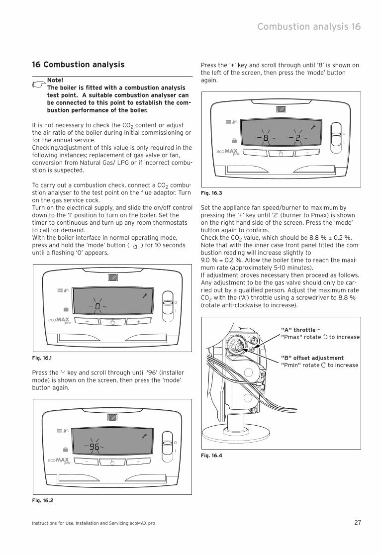
16 Combustion analysis
Note!The boiler is fitted with a combustion analysistest point. A suitable combustion analyser canbe connected to this point to establish the com-bustion performance of the boiler.
It is not necessary to check the CO2 content or adjustthe air ratio of the boiler during initial commissioning orfor the annual service.Checking/adjustment of this value is only required in thefollowing instances; replacement of gas valve or fan,conversion from Natural Gas/ LPG or if incorrect combu-stion is suspected.
To carry out a combustion check, connect a CO2 combu-stion analyser to the test point on the flue adaptor. Turnon the gas service cock.Turn on the electrical supply, and slide the on/off controldown to the ‘I’ position to turn on the boiler. Set thetimer to continuous and turn up any room thermostatsto call for demand.With the boiler interface in normal operating mode,press and hold the ‘mode’ button ( ) for 10 secondsuntil a flashing ‘0’ appears.
Fig. 16.1
Press the ‘-‘ key and scroll through until ‘96’ (installermode) is shown on the screen, then press the ‘mode’button again.
Fig. 16.2
Press the ‘+‘ key and scroll through until ‘8’ is shown onthe left of the screen, then press the ‘mode’ buttonagain.
Fig. 16.3
Set the appliance fan speed/burner to maximum bypressing the ‘+’ key until ‘2’ (burner to Pmax) is shownon the right hand side of the screen. Press the ‘mode’button again to confirm.Check the CO2 value, which should be 8.8 % ± 0.2 %.Note that with the inner case front panel fitted the com-bustion reading will increase slightly to 9.0 % ± 0.2 %. Allow the boiler time to reach the maxi-mum rate (approximately 5-10 minutes).If adjustment proves necessary then proceed as follows.Any adjustment to be the gas valve should only be car-ried out by a qualified person. Adjust the maximum rateCO2 with the (‘A’) throttle using a screwdriver to 8.8 %(rotate anti-clockwise to increase).
Fig. 16.4
"A" throttle –"Pmax" rotate to increase
"B" offset adjustment"Pmin" rotate to increase

16 Combustion analysis Fault Finding 17
Again in screen ‘8’, Set the appliance fan speed/burnerto minimum by pressing the ‘-‘ key until ‘1’ (burner toPmin) is shown on the right hand side of the screen.Press the ‘mode’ button again.
Fig. 16.5
Check the CO2 value, which should be 8.8 % ± 0.2 %. Ifadjustment proves necessary then proceed as follows.Adjustment of the CO2 at minimum rate is very coarse,so carefully adjust the CO2 with the (‘B’) offset adjust-ment using a 2mm allen key to 8.8 %, (rotate clockwiseto increase).After checking the combustion, press and hold the‘mode’ button for 10 seconds to return to the normalmode, showing the current flow temperature. Replacethe cap on the sampling point and refit the outer frontcase.
Note!Depending on the time to take the readings, thedisplay may default back to the normal mode, itmay be necessary to repeat steps 3,4 and 5 toadjust the appliance fan speed/burner.
17 Fault FindingLogical fault finding procedureThese checks must be carried out before attempting touse the fault finding guide.
1. Carry out electrical safety checks (see section ‘prelimi-nary electrical checks’ 13.1).
2.Check that the external electricity supply to the boileris on, and a supply of 230V is present at the boiler terminal strip.
3.Check that the gas supply to the boiler is on, that ithas been correctly purged and that an inlet pressureof 20mbar is available at the gas valve (see section‘gas supply’ 13.3).
4.Check that the main on/off control is set to the ‘on’position.
5.Set the central heating temperature to maximum.6.Check that all external controls are on and calling for
heat.7. Check that all manual circuit controls ie. bypass, radia-
tor valves are correctly adjusted.
17.1 Status ModeA series of status mode screens are available for currentboiler operating information.To display the status mode, proceed as follows:• With the interface in ‘normal’ mode, press and hold
the ‘mode’ button ( ) for 10 seconds until a flashing‘0’ appears (fig. 17.1).
• Press the ‘-‘ key and scroll through until ‘96’ (installermode) is shown on the screen, then press the ‘mode’button again.
• A series of screens are then available for service func-tions. An example is shown in fig. 17.2 (screen 23 ‘pro-duct code’ for the ecoMAX pro 18E).
Fig. 17.1
Fig. 17.2
Instructions for Use, Installation and Servicing ecoMAX pro28
18E 28E *
Output Min Max Min Max
Burner % CO2
Case on (± 0.2) 9.0 9.0 9.0 9.0
Case off (± 0.2) 8.8 8.8 8.8 8.8
Approx. gas rate
(after 10 mins 0.53 2.00 0.56 3.02
from cold) m3/h
* ecoMAX pro 28E only - for LPG see page 23

Fault Finding 17
Instructions for Use, Installation and Servicing ecoMAX pro 29
No. Description Comments 18E 28E Action
1 Central heating maximum output Set minimum to maximum product output (kW) 18 28 adjustable
2 Flue system pressure loss No function adjustable
3 Minimum temperature for Set minimum temperature 38 38 adjustable
Central Heating (22°, 28°, 38° or 50° C)
4 Maximum temperature for Set maximum temperature 80 80 adjustable
Central Heating (50°, 73° or 80° C)
5 Pump mode selection 1 – When room stat on (continuous) 1 1 adjustable
2 – When burner on (not continuous)
3 – Winter position/under floor heating (continuous)
6 External sensor ‘slope’ No function adjustable
7 External sensor ‘offset’ No function adjustable
8 Burner override Gas rate/CO2 0 – normal 0 0 adjustable
combustion check 1 – burner to Pmin
2 – burner to Pmax
Immediately communicated to the mainboard,
and reset to 0 after 15 minutes
9 Cylinder with NTC No function – however if altered to ‘1’ = ON fault adjustable
code 8 will be displayed ‘tank NTC fault’
10 Adaptive heating or night-day switch No function adjustable
11 Night-day setpoint (Delta value) No function adjustable
12 Central heating flow temperature °C Read only
13 Central heating return temperature °C Read only
14 Domestic hot water temp. No function Read only
15 Tank temp. No function Read only
16 DHW flow No function Read only
17 Extractor speed Extractor speed, RPM x 100 Read only
18 Burner demand power kW Read only
19 Working phase No function Read only
20 External sensor setpoint No function Read only
21 User interface version No function Read only
22 User interface revision No function Read only
23 Product code Code reference for ecoMAX pro 149 141 Read only
24 Min. fan speed RPM x 100 (800 – 6,000) 12 12 Read only
25 Max. fan speed RPM x 100 (2,000 – 6,000) 41 57 Read only
26 Fan speed during ignition 60 – 100% 80 60 Read only
27 Delta No function Read only
28 ‘Rechauffe’ No function Read only
29 Running hours Flame presence hours stored in E2prom every 2hrs Read only
30 Running hours Read only
31 Fault memory* Memory 1 Read only
32 Memory 2 Read only
33 Memory 3 Read only
34 Memory 4 Read only
35 Memory 5 Read only
36 Fault memory reset Memory can be reset by pressing ‘+’ and +/-
‘-‘ together

17 Fault Finding
Instructions for Use, Installation and Servicing ecoMAX pro30
17.2 Fault MemoryThe fault memory stores details of the five most recentfaults. To display the fault memory, proceed as follows;• With the interface in ‘normal’ mode, press and hold
the ‘mode’ button ( ) for 10 seconds until a flashing‘0’ appears.
• Press the ‘mode’ button again.• The 5 fault memory screens are now available to be
viewed, memory 1 being the most recent. Within eachmemory screen, 5 additional screens provide furtherinformation to assist the installer/engineer.
No. Memory screen type Comments
1 Fault code Fault code 1 – 26 (see page 31 – ‘Fault finding’)
2 Burner phase Working phase
3 DHW temperature No function
4 CH flow temperature °C at time of fault
5 Tank temperature No function
To cancel the fault memory mode proceed as follows;• Press and hold the ‘mode’ button for 10 seconds until
the screen returns to the ‘user’ mode.

Fault Finding 17
Instructions for Use, Installation and Servicing ecoMAX pro 31
Code Description Comment
F1 Ignition fault (lockout) No gas; Insufficient gas; Incorrect gas valve adjustment; Electrode defect;
Failed to light Ignition lead defect; Electronic igniter defective; Check air inlet duct;
Check connections to igniter unit
F4 Ignition fault (lockout) As above
Went out when lit
F5 Overheat fault Overheat stat operated; Maximum temperature exceeded;
Check thermistor connections; Air in system with thermistor at maximum
setting; Faulty overheat stat connection; Check that pump is wired into
appliance and not from programmer. This would cause no pump overrun
F6 Central heating flow NTC fault Flow NTC cable defective/broken NTC faulty
Flow thermistor not fitted correctly, Check pipe work configeration
F10 Central heating return NTC fault Return NTC cable defective/broken NTC faulty
Check that thermistor attached correctly to pipe.
F11 No reception by main board Connection fault between main PCB and interface; Faulty interface;
Faulty main PCB (processor), Check fan
F12 No reception by the local user interface As F.11
F13 Main board fault As F.11
F14 Central heating flow t° > 95° C System fault; Possible external pump failure; Check NTC on flow
Check that pump is wired into appliance and not from programmer.
This would cause no pump overrun
F16 Flame detection fault
(flame presence >5 s after burner stop) Gas valve defective
F17 Power supply <170 V Check electrical supply / polarity, Check fan
F18 Local user interface fault Connections; Faulty interface
F19 Central heating NTC unplugged Check NTC connection
F20 MMI software incompatible with IRIS software Possible connection fault
F24 Central heating return t° >90°C System fault; Possible external pump failure; Check NTC on return;
Check that pump is wired into appliance and not from programmer.
This would cause no pump overrun.
F25 Maximum temperature rise slope Possible external pump failure; Air in system restricting movement of water.
Insufficient circuit flow
F26 Maximum delta t Check NTC on return; System fault – too restrictive?; Possible pump failure
17.3 Fault CodesFault codes take priority over all other display functionsin the event of a system fault occurring.
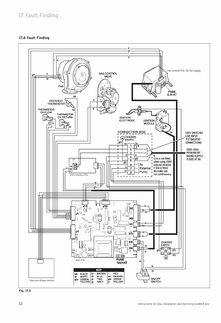
17 Fault Finding
Instructions for Use, Installation and Servicing ecoMAX pro32
Fig. 17.3
Fan control PCB / DC fan supply
room stat
frost stat
230 V interface PCB
Main PCB
Main user display interface
br
b
17.4 Fault Finding

Short Spare Parts 18
Instructions for Use, Installation and Servicing ecoMAX pro 33
18 Short Spare Parts
1
2
3
46
7
9
10
8
5
11
12
Fig. 18.1
Key No. Part No. Description
1 190260 Fan assembly
2 090750 Spark electrode
3 091258 Igniter unit
4 053574 Gas control valve
5 101771 Heating flow & return NTC (2)
6 101191 Overheat stat
7 130837 Main PCB
8 287452 Fan control PCB / DC Fan supply
9 256271 Mains/Reset Switch
10 130839 Main user display interface
11 050469 Burner - 18 E
11 050470 Burner - 28 E
12 130838 230V interface PCB

19 Boiler Specification
Instructions for Use, Installation and Servicing ecoMAX pro34
ecoMAX pro ecoMAX pro
18 E 28 E Units
Maximum CH heat input (net) 18.9 28.6 kW
CH heat output (80/60 °C) 5.0 - 18.3 5.3 - 28.2 kW
CH heat output (50/30 °C) 5.3 - 20.0 5.7 - 30.6 kW
SEDBUK Band A A
SAP Seasonal Efficiency 90.4 90.6 %
NOx Class 5 5
Electrical rating IP40 IP40
Inlet gas working pressure
required (natural gas) 20 20 mbar
Gas supply (G20) Gross CV (s.t.) 37.8 37.8 MJ/m3
Maximum gas rate 2.00 3.02 M3/h
Minimum gas rate 0.53 0.56 M3/h
Burner % CO2 (Case on) 9.0 +/-0.2 9.0 +/-0.2 %
Gas connection 15 mm Compression 15 mm Compression
Water connections 22 mm Compression 22 mm Compression
Condensate drain (internal diameter min.) 19 19 mm
Internal fuse ratings Fan supply PCB 3.15 AT Fan supply PCB 3.15 AT A
Main PCB 125 mAT Main PCB 125 mAT A
Maximum CH system pressure 3 3 bar
Weight 31 33 kg
Electrical supply 230/~50 230/~50 V~/Hz
External fuse 3 3 A
Power input 60 60 W
Case height 600 600 mm
Case width 375 375 mm
Case depth 334 334 mm
19 Boiler Specification

Instructions for Use, Installation and Servicing ecoMAX pro 35

83
49
39
GB
01
05
/20
04
· S
ub
ject
to
alt
era
tio
n
Head Office: Vaillant Ltd.
Service Solutions 0870 6060 777
Vaillant House Trident CloseMedway City Estate
Rochester Kent ME2 4EZ
Technical Advice 01634 292392