instructions wixey note always turn off the power and … · · 2010-08-021 instructions wixey...
TRANSCRIPT

1
INSTRUCTIONS
Wixey REMOTE PLANER READOUT MODEL WR550
1- Slide the sensor onto the scale
2- Select a mounting position The WR550 can be mounted to a variety of machines in a number of different ways. Either the scale or the sensor can be mounted to a non moving part of the machine as long as the travel direction of the sensor on the scale is in the proper direction as indicated by the arrow and + sign on the sensor decal. (FIG 1-5).
NOTE:
• Always turn off the power and unplug your machine before installing the WR550
The sensor can only go on the scale one way. Be sure the pattern on the sensor decal matches the pattern on the scale.
Scale
Sensor Sensor decal
+ +
TABLE MOVES UP AND DOWN
FIG 1
+ +
TABLE MOVES UP AND DOWN
FIG 2
+
+
TABLE MOVES UP AND DOWN
FIG 3
+
+ HEAD MOVES UP AND DOWN
FIG 4

2
3- Mounting the Scale
The scale mounting assembly can be located at any position along the scale. The “L” bracket can be removed and re-attached to the assembly in different positions (steps 1-3 in FIG 6). The slots in the “L” bracket are used to adjust the scale perpendicular to the table surface (FIG 7).
+
+
TABLE MOVES UP AND DOWN
FIG 5
JAWS
L-BRACKET
1. LOOSEN BOLT AND LOCK KNOB
SCALE MOUNTING ASSEMBLY
2. SLIDE THE SCALE MOUNTING ASSEMBLY TO ANY POSITION ON THE SCALE. (REMOVING THE SPRING MAY MAKE THIS STEP EASIER)
3. TIGHTEN THE BOLT AND LOCK KNOB. BE SURE THE JAWS ARE ALIGNED FLAT WHEN DONE. REPLACE THE SPRING IF IT WAS REMOVED. FIG 6
USING THE 5.5mm DRILL AND 2-M6 x 12mm LONG THREAD FORMING SCREWS ATTACH THE L-BRACKET TO THE MACHINE.
PUT A DROP OF OIL ON THE END OF THE SCREWS. USE A DRILL DRIVER OR RACTHET WRENCH AND PUSH THEM INTO THE HOLE WHILE TURNING SLOWLY
FIG 7
3
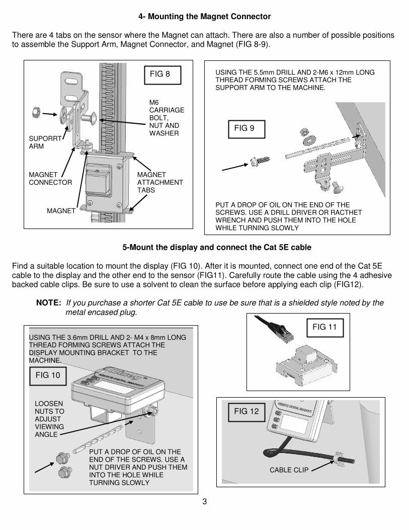
4- Mounting the Magnet Connector
There are 4 tabs on the sensor where the Magnet can attach. There are also a number of possible positions to assemble the Support Arm, Magnet Connector, and Magnet (FIG 8-9).
5-Mount the display and connect the Cat 5E cable Find a suitable location to mount the display (FIG 10). After it is mounted, connect one end of the Cat 5E cable to the display and the other end to the sensor (FIG11). Carefully route the cable using the 4 adhesive backed cable clips. Be sure to use a solvent to clean the surface before applying each clip (FIG12).
NOTE: If you purchase a shorter Cat 5E cable to use be sure that is a shielded style noted by the metal encased plug.
USING THE 5.5mm DRILL AND 2-M6 x 12mm LONG THREAD FORMING SCREWS ATTACH THE SUPPORT ARM TO THE MACHINE.
PUT A DROP OF OIL ON THE END OF THE SCREWS. USE A DRILL DRIVER OR RACTHET WRENCH AND PUSH THEM INTO THE HOLE WHILE TURNING SLOWLY
FIG 9
SUPORRT ARM
MAGNET
MAGNET CONNECTOR
MAGNET ATTACHMENT TABS
M6 CARRIAGE BOLT, NUT AND WASHER
FIG 8
FIG 11
USING THE 3.6mm DRILL AND 2- M4 x 8mm LONG THREAD FORMING SCREWS ATTACH THE DISPLAY MOUNTING BRACKET TO THE MACHINE.
PUT A DROP OF OIL ON THE END OF THE SCREWS. USE A NUT DRIVER AND PUSH THEM INTO THE HOLE WHILE TURNING SLOWLY
LOOSEN NUTS TO ADJUST VIEWING ANGLE
FIG 10
FIG 12
CABLE CLIP

4
6- Readout Operation
INSTALL 2 AAA BATTERIES (not included)
IN/MM
IN/MM
ABS/INC ON/OFF HOLD TO CAL
2.375
ABS IN
3333
8888
ABSOLUTE MEASURING MODE
INCH MODE TOGGLES BETWEEN INCHES AND MILLIMETERS
IN/MM
ABS/INC ON/OFF HOLD TO CAL
60.3
ABS mm
MILLIMETER MODE
ON/OFF and CALIBRATION
IN/MM
ABS/INC ON/OFF HOLD TO CAL
0.000
ABS IN
• PUSH MOMENTARILY TO TURN OFF AND ON
• HOLD FOR 3-5 SECONDS TO CALIBRATE AND SET TO 0.000
ABS/INC
IN/MM
ABS/INC ON/OFF HOLD TO CAL
2.375
ABS IN
3333
8888
IN/MM
ABS/INC ON/OFF HOLD TO CAL
2.375
ABS IN
3333 8888
IN/MM
ABS/INC ON/OFF HOLD TO CAL
0.000
INC IN
ABSOLUTE MEASURING MODE
TOGGLES BETWEEN ABSOLUTE AND INCREMENTAL
INCREMENTAL MODE RE-SETS TO 0.000
TOGGLE BACK TO ABS MODE AND THE CALIBRATED DIMENSION IS REMEMBERED

5
7-Calibration
Follow steps 1-7 below to accurately calibrate your readout.
ABS IN
1. RUN A FLAT BOARD 1” THICK OR LESS THROUGH THE MACHINE MAKING SURE THAT MATERIAL IS REMOVE FROM THE ENTIRE TOP SURFACE. DO NOT CHANGE THE SETTING WHEN DONE.
2. CUT A SMALL SECTION OF BOARD TAKING CARE TO AVOID THE END WHICH MAY HAVE SOME SNIPE
IN/MM
ABS/INC ON/OFF HOLD TO CAL
0.980
ABS IN
7. REMOVE THE BOARD ALLOWING THE JAWS TO CLOSE COMPLETELY. TIGTHEN THE LOCK KNOB. THE DISPLAY SHOWS THE BOARD THICKNESS AND THE READOUT IS NOW CALIBRATED.
3. LOOSEN THE LOCK KNOB
4. LIFT THE SCALE UPWARDS TO OPEN THE JAWS. DO NOT OPEN MORE THAN 1”.
5. PLACE THE CUT PIECE OF BOARD BETWEEN THE JAWS AND MAKE SURE THEY CLAMP FLAT AND TIGHT.
IN/MM
ABS/INC ON/OFF HOLD TO CAL
0.000
6. PRESS AND HOLD FOR 3-5 SECONDS TO SET TO 0.000
ABS IN
6
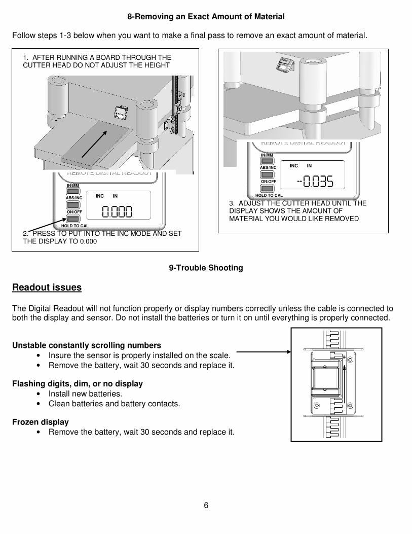
8-Removing an Exact Amount of Material
Follow steps 1-3 below when you want to make a final pass to remove an exact amount of material.
9-Trouble Shooting
Readout issues The Digital Readout will not function properly or display numbers correctly unless the cable is connected to both the display and sensor. Do not install the batteries or turn it on until everything is properly connected. Unstable constantly scrolling numbers
• Insure the sensor is properly installed on the scale.
• Remove the battery, wait 30 seconds and replace it. Flashing digits, dim, or no display
• Install new batteries.
• Clean batteries and battery contacts. Frozen display
• Remove the battery, wait 30 seconds and replace it.
IN/MM
ABS/INC ON/OFF HOLD TO CAL
-0.035
INC IN
3. ADJUST THE CUTTER HEAD UNTIL THE DISPLAY SHOWS THE AMOUNT OF MATERIAL YOU WOULD LIKE REMOVED
IN/MM
ABS/INC ON/OFF HOLD TO CAL
0.000
INC IN
1. AFTER RUNNING A BOARD THROUGH THE CUTTER HEAD DO NOT ADJUST THE HEIGHT
2. PRESS TO PUT INTO THE INC MODE AND SET THE DISPLAY TO 0.000

7
Loses calibration
• Make sure that your machine is properly grounded.
• Route the cable away from electric motors or other electrical controls.
• Check for dirt on the scale or inside the sensor. Remove and clean if needed.
• Check for static discharges from a nearby dust collector or other source Note: If a static discharge from your finger zaps the readout or a nearby dust collector happens to zap your machine it can cause this error. Make sure the dust collector is properly grounded and the dust port on your saw is grounded to the ground wire inside the dust collector hose.
Accuracy Issues Small accuracy errors of 1/16” or less
• Be sure the jaws fit tight and flat when in use and when calibrating.
• Be sure the lock knob is tight.
• Check for loose or flexing brackets.
• Make sure that the scale is perpendicular to the table in all planes. Large accuracy errors of .200” or more
• An error of exactly .200" is a very common error number with these devices or even a multiple of it like .400, .600, 1.200 etc. Usually this only happens when the readout is either moved very quickly (more than 3 feet per second) Follow the same steps outlined in the “Loses calibration” section above.

8
For questions, comments, spare parts, and application examples go to: www.wixey.com
ITEM PART NO.
DESCRIPTION QTY. ITEM PART NO.
DESCRIPTION QTY.
1 WR5501 sensor 1 17 WR5519 M3 hex nut 1
2 WR5502 display 1 18 WR5520 M6 flat washer 4
3 WR5503 scale 1 19 WR5521 M6 x 12mm long carriage bolt 1
4 WR5504 sensor strip 1 20 WR5506 extension spring 1
5 WR5508 wedge 1 21 WR5522 5.5mm drill bit 1
6 WR5509 "L" bracket 1 22 WR5523 3.6mm drill bit 1
7 WR5510 slide 1 23 WR5524 M6 x 12mm long thread forming screw 4
8 WR5511 lower jaw 1 24 WR5525 cable clip 4
9 WR5512 wedge nut 1 25 WR5526 M6 hex nut 1
10 WR5513 upper jaw 1 26 WR5527 M5 lock nut 2
11 WR5514 M6 x 10mm long flat head screw 1 27 WR5528 M5 x 12mm long carriage bolt 2
12 WR5515 knob 1 28 WR5529 display mounting bracket 2
13 WR5516 M6 x 12mm long hex head screw 1 29 WR5530 M6 x 16mm long hex head screw 2
14 WR5517 support arm 1 30 WR5507 Cat 5e shielded cable 2M long 1
15 WR5518 magnet mount 1 31 WR5531 M4 x 8mm long thread forming screw 2
16 WR5505 magnet 1
31
30