instructor’s manual and test bank - solutions guides
TRANSCRIPT

Instructor’s Manual and Test Bank
For
MACHINE ELEMENTS IN MECHANICAL DESIGN
Sixth Edition
Robert L. Mott, University of Dayton Edward M. Vavrek, Purdue University Jyhwen Wang, Texas A&M University
Boston Columbus Indianapolis New York San Francisco Hoboken Amsterdam Cape Town Dubai London Madrid Milan Munich Paris Montreal
Toronto Delhi Mexico City Sao Paolo Sydney Hong Kong Seoul Singapore Taipei
Tokyo

____________________________________________________________________________
Copyright © 2018 by Pearson Education, Inc. or its affiliates. All Rights Reserved. Printed in the United States of America. This publication is protected by copyright, and permission should be obtained from the publisher prior to any prohibited reproduction, storage in a retrieval system, or transmission in any form or by any means, electronic, mechanical, photocopying, recording, or otherwise. For information regarding permissions, request forms and the appropriate contacts within the Pearson Education Global Rights & Permissions Department, please visit www.pearsoned.com/permissions/.
Instructors of classes using Machine Elements in Mechanical Design, Sixth Edition, by Robert L. Mott, Edward M. Vavrek, Jyhwen Wang, may reproduce material from the Instructor’s Resource Manual and Test Bank for classroom use. 10 9 8 7 6 5 4 3 2 1 ISBN-10: 013444129X ISBN-13: 9780134441290
www.pearsonhighered.com

iii
Table of Contents
Chapter 1 The Nature of Mechanical Design 1
Chapter 2 Materials in Mechanical Design 3
Chapter 3 Stress and Deformation Analysis 11
Chapter 4 Combined Stresses and Stress Transformations 50
Chapter 5 Design for Different Types of Loading 121
Chapter 6 Columns 158
Chapter 7 Belt Drives, Chain Drives and Wire Rope 178
Chapter 8 Kinematics of Gears 193
Chapter 9 Spur Gear Design 225
Chapter 10 Helical Gears, Bevel Gears and Wormgearing 275
Chapter 11 Keys, Couplings, and Seals 311
Chapter 12 Shaft Design 316
Chapter 13 Tolerances and Fits 354
Chapter 14 Rolling Contact Bearings 360
Chapter 16 Plain Surface Bearings 365
Chapter 17 Linear Motion Elements 372
Chapter 18 Springs 377
Chapter 19 Fasteners 396
Chapter 20 Machine Frames, Bolted Connections and Welded Joints 398
Chapter 21 Electric Motors and Controls 407
Chapter 22 Motion Control: Clutches and Brakes 411

1
CHAPTER 1 THE NATURE OF MECHANICAL DESIGN
Problems1‐14requirethespecificationoffunctionsanddesignrequirementsfordesignprojectsandhavenouniquesolutions.15. D 1.75in25.4mm/in 44.5mm16. L 46.0m0.3048m/ft 14.0m17. T 12500lbin0.1130Nm/lbin 1418Nm18. A 4.12in2645.2mm2/in2 2658mm219. Sectionmodulus S 14.8in31.639104mm3/in3 2.43105mm320. Momentofinertia I 88.0in44.162105mm4/in4 3.66107mm421. Given:Amin 750mm2:InU.S.units;Amin 1.162in2
U.S.Angle–FromAppendix15‐1:L223/8;A 1.36in2 890mm2
SIAngle–FromAppendix15‐3:Angle75755;A 864mm2
22. Power P 7.5hp745.7W/hp 5.59103W 5.59kW23. Ultimatetensilestrengthsu 127ksi6.895MPa/ksi 876MPa24. Given:Steelshaft;D 35mm 0.035m;L 675mm 0.675m
Find:Weightoftheshaft:Weight massg;g 9.81m/s2
Mass densityvolume;Densityofsteel 7680kg/m3 FromAppendix3
Volume V arealength D2/4L
V 0.035m 2/40.675m 6.4910‐4m3
Mass 7680kg/m36.4910‐4m3 4.98kg
Weight mg 4.98kg9.81m/s2 48.9kgm/s2 48.9N

2
25. Given:Foratorsionalspring,Torque 180lbinfor35ofrotation.
Findthescaleofthespring Torqueperunitofrotation.Expresstheresultinboth
U.S.andSIunits.
T 180lbin0.1130Nm/lbin 20.3Nm
Angle 35rad/180 0.611radians
Scale T/ 180lbin/35 5.14lbin/degree
Scale T/ 20.3Nm/0.611rad 33.3Nm/rad
26. Given:12.5hpmotoroperating16h/day,5days/week
Computetheenergy,E,usedbythemotorforoneyearinbothU.S.andSIunits.
E 12.5hp16h/day5days/wk52wks/year550ftlb/s/hp3600s/h
E 1.031011ftlb/year
E 1.031011ftlb/year1.356J/ftlb1.0Nm/J1.0W/Nm/s1h/3600s
E 38.8106Wh/year 38.8MWh/year
27. Given:Viscosity 3.75reyn 1.0lbs/in2 /reyn144in2/ft2 540lbs/ft2
3.5lbs/in24.448N/lb1.0in2/645.2mm2106mm2/m2 25.9103Ns/m2
28. Given:n 1750rpm;24h/day;5.0years.Findlifeinnumberofrevolutions.
Life 1750rev/min24h/day60min/h365days/year5years
Life 4.60109revolutions

3
From Eq. 2-5:

4
2
17)
17)
SAE
(Table 2-8)
(Table 2-9)
SAE
from SAE 1040, 4140, 4340, 4640(Table 2-9)
from SAE 1040, 4140, 4340, 4640steels (Table 2-9)
SAE 1080 steel is a reasonable choice.
SAE 5160 OQT 1000

5
SAE 1040 WQT
SAE 1040 and
SAE 1040 WQT
SAE 1040 and
SAE 1015, 1020,
[See Appedix A-5.]
ASTM A992 Structural steel is used for most wide-flange beam shapes.

6
Problem 38 (Continued)
ASTM A536, Grade 100-70-03 is a ductile iron with a tensile strength of 100 ksi (689 MPa); a yield strength of 70 ksi (483 MPa); 3% elongation (brittle); modulus of elasticity (stiffness) of 24x106 psi (165 GPa). ASTM A47, Grade 32510 is a malleable iron with a tensile strength of 50 ksi (345 MPa); a yield strength of 32.5 ksi (224 MPa); 10% elongation (ductile); modulus of elasticity (stiffnes) of 26x106 (179 GPa.
(Table 2-11)
Aluminum 7178-T6 has the highest strength; tensile strength = 88 ksi (607 MPa); yield strength = 78 ksi (538 MPa).
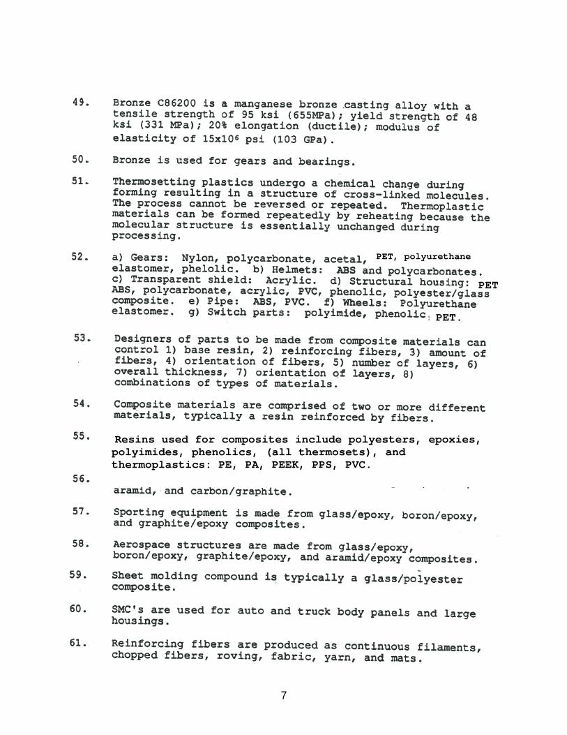
7
PET, polyurethane
PET.
PET
Resins used for composites include polyesters, epoxies, polyimides, phenolics, (all thermosets), and thermoplastics: PE, PA, PEEK, PPS, PVC.

8
See Section 2-17, Table 2-16, Figures 2-23 and 2-24 for
answers to Questions 74 to 100.
Questions 70-73 refer to Figure 2-23 and Table 2-17 in the text.
General conclusions from Questions 70-73: The specific strengths of the metals listed range from 0.194x10⁶ to 1.00x10⁶, approximately a factor of 5.0. The specific stiffnesses are very nearly equal for all metals listed, approximately 1.0x108 in. The specific strengths of the composites listed range from 1.87 to 4.88x10⁶ in, much higher than any of the metals. Glass/epoxy has a specific stiffness about 2/3 that of the metals. The other composites listed range from 2.2 to 8.3 times as stiff as the metals.

9

10

11
CHAPTER 3
STRESS AND DEFORMATION ANALYSIS
Direct Tension and Compression
1. / ; 18 12 /4 .
4500N/141.4mm 31.8N/mm .
/ .
.
2. / 3500N/ 10 /4 mm .
3. / 20 10 N/ 10 ∙ 30 mm .
4. / 860lb/ 0.40
5. / 1900lb/ 0.375 /4
6. / ; 12 144mm ; 5000N/144mm .
/
mm
a) SAE 1020; 207GPa 207 10 N/mm ; .
b) SAE 8650; 207GPa; .
c) Ductile iron A536(60-40-18); 165GPa; .
d) Aluminum 6061-T6; 69GPa; .
e) Titanium Ti-6AL-4V; 114GPa; .
f) PVC; TensileModulus 2410MPa 2410N/mm ; .
g) Phenolic; 7580MPa; .
Note: The stress is close to the ultimate for f and g.

12
7. / ;
2.25 2.01 in .
. / .
.
/ 2556lb/1.02in
8. 2500lb; Σ 0 2500 75 60
2500 75/60 3125lb Tensileforcein
. .
9. 2 1500lb
1500/ 2 45°
10. / ; Required /
/0.0589in /4
. .
11. 15°; 2898lb
2898/18000 0.161in ; . .
2.25in 2.01in
50
60
75
1500 lb
A
B
C

13
12. JointB
JointA
Stresses:
AB,BC: .
.
BD: .
.
AD,CD: 30 20 500mm
.
.
13. FigureP3‐13
Σ 0 6000 6 12000 12 18
10000lb
Σ 0 12000 6 6000 12 18
8000lb
Note: sin = 8/10 = 0.80; cos = 6/10 = 0.60
30°
5.25kN
5.25 kN 10.5kN 5.25
30°30°
10.5kN
10.5kN
6
18
66
6000 12000
8 810
AD sin 30 = 5.25 kN ↓ AD = 10.5 kN = CD AB = AD cos 30 = 9.09 kN = BC→
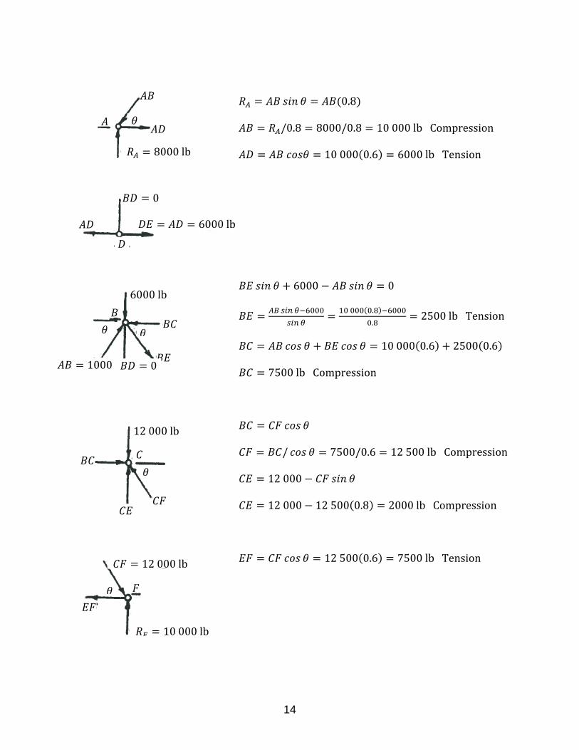
14
0.8
/0.8 8000/0.8 10000lbCompression
10000 0.6 6000lbTension
6000 0
.
.2500lbTension
10000 0.6 2500 0.6
7500lbCompression
/ 7500/0.6 12500lbCompression
12000
12000 12500 0.8 2000lbCompression
12500 0.6 7500lbTension
6000lb
0
6000lb
01000
8000lb
12000lb
12000lb
10000lb

15
AreasofMembers: AppendixA5,A6 Stresses:
, , 2 0.484 0.968in 6000/0.968
, , 0.484in 7500/0.968
, , 2 1.21 2.42in
Note:Compressionmembersmustbe 2500/0.484
checkedforcolumnbuckling 2000/0.484
10000/2.42
7500/2.42
12500/2.42
14. 2.65 1.40 2 1.40 0.5 /2 4.41in
/ 52000 /4.41
15. 80 40 40 /4 4457mm
/ 640 10 N/4457mm .
Direct Shear Stress
16. Pindiameter 0.50in;Doubleshear
2 /4 2 0.50 /4 0.3927in
/
MemberBC:
Σ 0 2500 75 60
2500 75/60 3125lb
And 3125lb
75
50
60
2500 lb
FigureP3 8B

16
2500lb
Resultantat : √3125 2500 4002lb
PinsAandC: / 3125lb/0.3927in
PinB: / 4002lb/0.3927in
17. FromProblem3‐9:Forceineachrod 1500lb/2
For 40°: 1167lb shearforcesonupperpins
Assumedoubleshear: 2 /4 2 0.75 /4 0.8836in
/ 1167lb/0.8836in
Lowerpin: 1500lb
/ 1500lb/0.8836in
18. AnalysisfromProblems9and17.Let 15°
1500lb/ 2 1500lb/ 2 15° 2898lb
/ 2898lb/0.8836in
19. SeeFigure3‐7:Keyisinshear; ∙ 12 45 540mm
Torque/Radius 1600N ∙ m/30mm 53333N
/
98.8N/mm .
20. Punch–Fig.P3‐20: 2.50 2.00 1.50 √0.5 2.5 0.060
8.55 0.060 0.513in
/ 52000lb/0.513in
21. Punch–FigureP3‐21.Perimeter 60 2 30 2 7.5 3 205.7mm
205.7 2.0 411.4mm
/
. 547N/mm