instrument and procedure manual - pennsylvania well water
TRANSCRIPT

CAT. NO. 46500-88
PORTABLE TURBIDIMETERModel 2100P
Instrument and Procedure Manual
© Hach Company, 1991-1999. dd/rb 6-3-98 7 EDAll rights reserved. Printed in the U.S.A. Rev. 1, 8/99

ii

TABLE OF CONTENTS
CERTIFICATION ............................................................................ vSAFETY PRECAUTIONS .......................................................... viiSPECIFICATIONS ........................................................................ ix
OPERATION ......................................................................................1
SECTION 1 DESCRIPTION......................................................... 31.1 General Description......................................................................... 31.2 Accessories ...................................................................................... 41.3 Principle of Operation ..................................................................... 41.4 Preparation for Use.......................................................................... 5
1.4.1 Unpacking .............................................................................. 51.4.2 Battery Installation................................................................. 51.4.3 Using the Battery Eliminator and Rechargeable Batteries..... 61.4.4 Calibration.............................................................................. 6
SECTION 2 TURBIDITY MEASUREMENT .......................... 72.1 Operating Controls and Indicators................................................... 72.2 Turbidity Measurement ................................................................... 7
2.2.1 Turbidity Measurement Procedure......................................... 82.2.2 Measurement Notes ............................................................. 10
2.3 Measurement Techniques .............................................................. 102.3.1 Cleaning Sample Cells ......................................................... 112.3.2 Oiling the Sample Cell......................................................... 112.3.3 Orienting Sample Cells ........................................................ 122.3.4 Matching multiple sample cells ........................................... 152.3.5 Removing Bubbles (Degassing)........................................... 182.3.6 Measuring Overrange Samples ............................................ 212.3.7 Condensation (fogging) ....................................................... 212.3.8 Calibration............................................................................ 212.3.9 Representative Sampling...................................................... 22
iii
TABLE OF CONTENTS, continued
iv
SECTION 3 OPERATION .......................................................... 233.1 Operational Controls and Indicators ............................................. 233.2 Using the Read Key ...................................................................... 25
3.2.1 Continuous Reading ............................................................ 253.3 Using the Signal Averaging Key................................................... 253.4 Using the Range Selection Key .................................................... 263.5 Restoring the Default Calibration ................................................. 263.6 Calibration .................................................................................... 27
3.6.1 StablCal Stabilized Formazin Standards ............................. 273.6.2 Formazin Primary Standards ............................................... 293.6.3 Calibrating the Turbidimeter ............................................... 343.6.4 Using Gelex® Secondary Turbidity Standards.................... 44
MAINTENANCE ............................................................................ 47
SECTION 4 MAINTENANCE ................................................... 494.1 Cleaning ........................................................................................ 494.2 Battery Replacement..................................................................... 494.3 Lamp Replacement ....................................................................... 49
SECTION 5 TROUBLESHOOTING........................................ 575.1 Using the Diagnostic Functions Key ............................................ 57
5.1.1 Basic Diagnostic Codes....................................................... 575.2 The Diagnostic Procedure............................................................. 585.3 Other Instrument Diagnostics ....................................................... 60
5.3.1 Display Test......................................................................... 605.4 Error Messages ............................................................................. 60
5.4.1 Flashing Numeric Display................................................... 605.4.2 E Messages.......................................................................... 605.4.3 CAL? ................................................................................... 60
GENERAL INFORMATION....................................................... 63REPLACEMENT PARTS & ACCESSORIES ....................... 65HOW TO ORDER ......................................................................... 67REPAIR SERVICE........................................................................ 68WARRANTY................................................................................... 69

CERTIFICATION
Hach Company certifies this instrument was tested thoroughly,inspected and found to meet its published specifications when it wasshipped from the factory.
The Model 2100P Portable Turbidimeter has been tested and is certifiedas indicated to the following instrumentation standards:
Product SafetyBattery/Eliminator Power Supply Only:120 Vac, 60 Hz, UL Listed & CSA Certified, Class 2230 Vac, 50 Hz, VDE Approved, GS & CE marked
Immunity2100P Turbidimeter Tested with external Battery/EliminatorPower Supply:EN 50082-1 (European Generic Immunity Standard) per 89/336/EECEMC: Supporting test records with Dash Straus and Goodhue, Inc.(now Intertek Testing Services), certified compliance byHach Company.
Standards include:IEC 801-2 Electro-Static DischargeIEC 801-3 Radiated RF Electro-Magnetic FieldsIEC 801-4 Electrical Fast Transients/Burst
Emissions2100P Turbidimeter Tested with external Battery/EliminatorPower Supply:EN 50081-1 (Emissions) per 89/336/EEC EMC: Supporting testrecords by Amador Corp. (now TUV Product Services), certifiedcompliance by Hach Company
Standards include:EN 55022 (CISPR 22) Emissions, Class B Limits
Canadian Radio Interference-Causing Regulation, Chapter 1374,Class A: Supporting test records by Amador Corp. (now TUV ProductServices), certified compliance by Hach Company
This Class A digital apparatus meets all requirements of the CanadianInterference-Causing Equipment Regulations.
Cet appareil numérique de la classe A respecte toutes les exigences duRèglement sur le matériel brouilleur du Canada.
v
CERTIFICATION, continued
FCC Part 15, Class “A” Limits: Supporting test records by AmadorCorp. (now TUV Product Services), certified compliance byHach Company.
This device complies with Part 15 of the FCC Rules. Operation issubject to the following two conditions:
1. this device may not cause harmful interference, and
2. this device must accept any interference received, includinginterference that may cause undesired operation.
Changes or modifications to this unit not expressly approved by theparty responsible for compliance could void the user’s authority tooperate the equipment.
This equipment has been tested and found to comply with the limitsfor a Class A digital device, pursuant to Part 15 of the FCC Rules.These limits are designed to provide reasonable protection againstharmful interference when the equipment is operated in a commercialenvironment. This equipment generates, uses, and can radiate radiofrequency energy and, if not installed and used in accordance withthe instruction manual, may cause harmful interference to radiocommunications. Operation of this equipment in a residential area maycause harmful interference in which case the user will be required tocorrect the interference at his own expense.
The following techniques of reducing interference problems areapplied easily:
1. Disconnect the battery eliminator from it’s power source andfrom the 2100P Portable Turbidimeter to verify if it is the sourceof the interference
2. If the battery eliminator for the 2100P Portable Turbidimeter isplugged into the same outlet as the device with which it isinterfering, try another outlet.
3. Move the 2100P Portable Turbidimeter away from the devicereceiving the interference.
4. Reposition the receiving antenna for the device receivingthe interference.
5. Try combinations of the above.
vi
SAFETY PRECAUTIONS
Please read this entire manual before unpacking, setting up, oroperating this instrument. Pay particular attention to all danger andcaution statements. Failure to do so could result in serious injury to theoperator or damage to the equipment.
To ensure the protection provided by this equipment is not impaired, donot use or install this equipment in any manner other than that which isspecified in this manual.
Use of Hazard InformationIf multiple hazards exist, this manual will use the signal word (Danger,Caution, Note) corresponding to the greatest hazard.
DANGERIndicates a potentially or imminently hazardous situation which,if not avoided, could result in death or serious injury.
CAUTIONIndicates a potentially hazardous situation that may result in minoror moderate injury.
NOTEInformation that requires special emphasis.
Precautionary LabelsRead all labels and tags attached to the instrument. Personal injury ordamage to the instrument could occur if not observed.
This symbol, if noted on the instrument, references the instructionmanual for operational and/or safety information.
vii

viii
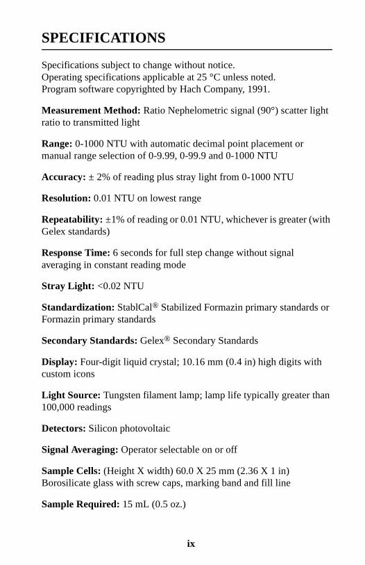
SPECIFICATIONS
Specifications subject to change without notice.Operating specifications applicable at 25 °C unless noted.Program software copyrighted by Hach Company, 1991.
Measurement Method: Ratio Nephelometric signal (90°) scatter lightratio to transmitted light
Range: 0-1000 NTU with automatic decimal point placement ormanual range selection of 0-9.99, 0-99.9 and 0-1000 NTU
Accuracy: ± 2% of reading plus stray light from 0-1000 NTU
Resolution: 0.01 NTU on lowest range
Repeatability: ±1% of reading or 0.01 NTU, whichever is greater (withGelex standards)
Response Time: 6 seconds for full step change without signalaveraging in constant reading mode
Stray Light: <0.02 NTU
Standardization: StablCal® Stabilized Formazin primary standards orFormazin primary standards
Secondary Standards: Gelex® Secondary Standards
Display: Four-digit liquid crystal; 10.16 mm (0.4 in) high digits withcustom icons
Light Source: Tungsten filament lamp; lamp life typically greater than100,000 readings
Detectors: Silicon photovoltaic
Signal Averaging: Operator selectable on or off
Sample Cells: (Height X width) 60.0 X 25 mm (2.36 X 1 in)Borosilicate glass with screw caps, marking band and fill line
Sample Required: 15 mL (0.5 oz.)
ix

SPECIFICATIONS, continued
Storage Temperature: -40 to 60 °C (-40 to 140 °F) (instrument only)
Operating Temperature: 0 to 50 °C (32 to 122 °F) (instrument only)
Operating Humidity Range: 0 to 90% RH noncondensing at 30 °C;0 to 80% RH noncondensing at 40 °C;0 to 70% RH noncondensing at 50 °C
Power Requirements: Four AA Alkaline cells or optionalbattery eliminator
Battery Life: Typically 300 tests with signal average mode off;180 tests with signal average mode on
Battery Eliminator (optional):For 120 V eliminator: CSA and UL approved for 120 VAC ±10%,60 Hz, 6 V at 800 mA DC output
For 230 V eliminator: CE (VDE) approval pending for 230 VAC±10%, 50 Hz, 6 V at 900 mA DC output
Enclosure: High impact ABS plastic
Dimensions: 22.2 X 9.5 X 7.9 cm (8.75 X 3.75 X 3.12 in)
Instrument Weight: 520 kg (1 lb 2.5 oz)
Shipping Weight: 3.1 kg (6 lbs 8.5 oz)
x

OPERATION
DANGERHandling chemical samples, standards, and reagents can be dangerous.Review the necessary Material Safety Data Sheets and become familiar withall safety procedures before handling any chemicals.
DANGERLa manipulation des échantillons chimiques, étalons et réactifs peut êtredangereuse. Lire les Fiches de Données de Sécurité des Produits (FDSP) etse familiariser avec toutes les procédures de sécurité avant de manipuler tousles produits chimiques.
PELIGROLa manipulación de muestras químicas, estándares y reactivos puede serpeligrosa. Revise las fichas de seguridad de materiales y familiarícese con losprocedimientos de seguridad antes de manipular productos químicos.
GEFAHRDa das Arbeiten mit chemischen Proben, Standards und Reagenzien mitGefahren verbunden ist, empfiehlt die Hach Company dem Benutzer dieserProdukte dringend, sich vor der Arbeit mit sicheren Verfahrensweisen unddem richtigen Gebrauch der Chemikalien vertraut zu machen und alleentsprechenden Materialsicherheitsdatenblätter aufmerksam zu lesen.
PERIGOA manipulação de amostras, padrões e reagentes químicos pode serperigosa. Reveja a folha dos dados de segurança do material e familiarize-secom todos os procedimentos de segurança antes de manipular quaisquerprodutos químicos.

2
SECTION 1 DESCRIPTION
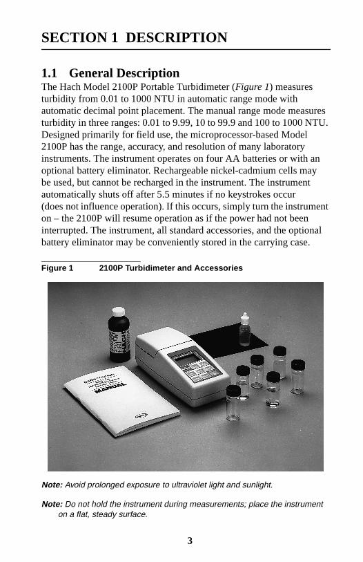
1.1 General DescriptionThe Hach Model 2100P Portable Turbidimeter (Figure 1) measuresturbidity from 0.01 to 1000 NTU in automatic range mode withautomatic decimal point placement. The manual range mode measuresturbidity in three ranges: 0.01 to 9.99, 10 to 99.9 and 100 to 1000 NTU.Designed primarily for field use, the microprocessor-based Model2100P has the range, accuracy, and resolution of many laboratoryinstruments. The instrument operates on four AA batteries or with anoptional battery eliminator. Rechargeable nickel-cadmium cells maybe used, but cannot be recharged in the instrument. The instrumentautomatically shuts off after 5.5 minutes if no keystrokes occur(does not influence operation). If this occurs, simply turn the instrumenton – the 2100P will resume operation as if the power had not beeninterrupted. The instrument, all standard accessories, and the optionalbattery eliminator may be conveniently stored in the carrying case.
Figure 1 2100P Turbidimeter and Accessories
Note: Avoid prolonged exposure to ultraviolet light and sunlight.
Note: Do not hold the instrument during measurements; place the instrumenton a flat, steady surface.
3

SECTION 1, continued
1.2 AccessoriesAccessories supplied with the turbidimeter include three samplecells; three Gelex® Secondary Standards; one 100 mL bottle each of:<0.1-NTU, 20-NTU, 100-NTU, and 800-NTU StablCal® StabilizedFormazin Standards; 4 AA alkaline batteries; 15 mL of silicone oil;oiling cloth; carrying case; instrument manual; and quick reference card.
1.3 Principle of OperationThe Model 2100P Portable Turbidimeter operates on the nephelometricprinciple of turbidity measurement. This instrument meets the designcriteria specified by the United States Environmental ProtectionAgency, Method 180.1.
The optical system* (Figure 2) includes a tungsten-filament lamp, a 90°detector to monitor scattered light and a transmitted light detector. Theinstrument's microprocessor calculates the ratio of the signals from the90° and transmitted light detectors. This ratio technique corrects forinterferences from color and/or light absorbing materials (such asactivated carbon) and compensates for fluctuations in lamp intensity,providing long-term calibration stability. The optical design alsominimizes stray light, increasing measurement accuracy.
Figure 2 Ratio Optical System
* Patent number 4,198,161; other patents pending.
4

SECTION 1, continued
1.4 Preparation for Use
1.4.1 UnpackingRemove the instrument and accessories from the shipping box andinspect them for damage that may have occurred due to rough handlingor extreme weather conditions. Verify the following are present:
• Model 2100P Portable Turbidimeter
• Instrument Manual (with quick reference card)
• StablCal Stabilized Formazin Standard, <0.1 NTU*, 100 mLStablCal Stabilized Formazin Standard, 20 NTU, 100 mLStablCal Stabilized Formazin Standard, 100 NTU, 100 mLStablCal Stabilized Formazin Standard, 800 NTU, 100 mL
• Standardization Kit containing Gelex Secondary Standards(0-10, 0-100 and 0-1000 ranges) plus nine sample cells with caps.
• Silicone Oil, 15-mL (0.5 oz) dropping bottle
• Oiling Cloth
• Carrying Case
• Four AA alkaline batteries
If any of the items are missing or damaged, please contact the CustomerService Department, Hach Company, Loveland, Colorado. The toll-freenumber in the United States is 800-227-4224. International customersshould contact the Hach office or authorized distributor serving yourarea. Refer to REPAIR SERVICE on page 68. Please do not return theinstrument without prior authorization from Hach.
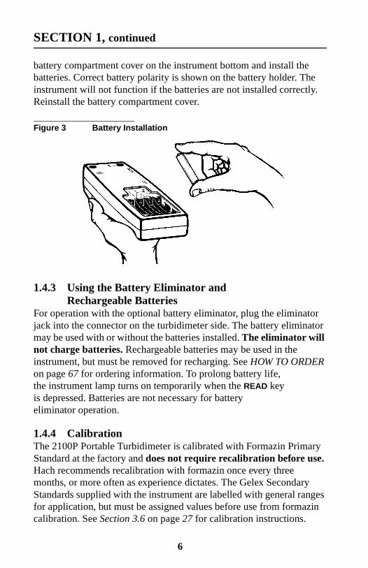
1.4.2 Battery InstallationThe instrument is shipped completely assembled without the batteriesinstalled. Before use, install the four AA alkaline batteries or connectthe battery eliminator (Figure 3). For battery operation, remove the
* Used in place of the dilution water standard when performing acalibration.
5
SECTION 1, continued
battery compartment cover on the instrument bottom and install thebatteries. Correct battery polarity is shown on the battery holder. Theinstrument will not function if the batteries are not installed correctly.Reinstall the battery compartment cover.
Figure 3 Battery Installation
1.4.3 Using the Battery Eliminator andRechargeable Batteries
For operation with the optional battery eliminator, plug the eliminatorjack into the connector on the turbidimeter side. The battery eliminatormay be used with or without the batteries installed. The eliminator willnot charge batteries. Rechargeable batteries may be used in theinstrument, but must be removed for recharging. See HOW TO ORDERon page 67 for ordering information. To prolong battery life,the instrument lamp turns on temporarily when the READ keyis depressed. Batteries are not necessary for batteryeliminator operation.
1.4.4 CalibrationThe 2100P Portable Turbidimeter is calibrated with Formazin PrimaryStandard at the factory and does not require recalibration before use.Hach recommends recalibration with formazin once every threemonths, or more often as experience dictates. The Gelex SecondaryStandards supplied with the instrument are labelled with general rangesfor application, but must be assigned values before use from formazincalibration. See Section 3.6 on page 27 for calibration instructions.
6
SECTION 2 TURBIDITY MEASUREMENT
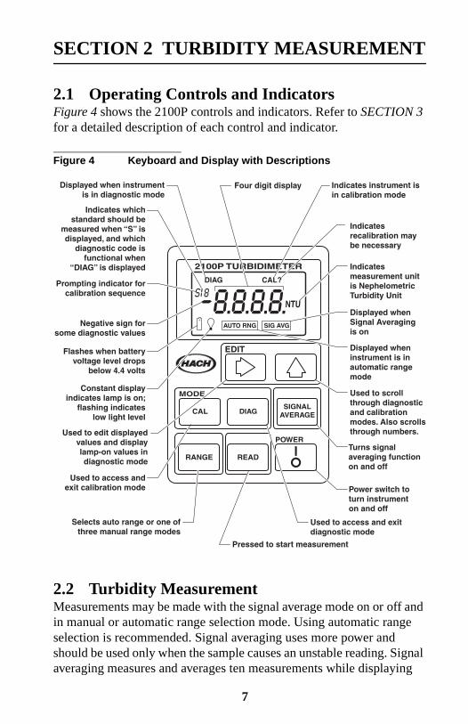
2.1 Operating Controls and IndicatorsFigure 4 shows the 2100P controls and indicators. Refer to SECTION 3for a detailed description of each control and indicator.
Figure 4 Keyboard and Display with Descriptions
2.2 Turbidity MeasurementMeasurements may be made with the signal average mode on or off andin manual or automatic range selection mode. Using automatic rangeselection is recommended. Signal averaging uses more power andshould be used only when the sample causes an unstable reading. Signalaveraging measures and averages ten measurements while displaying
7
SECTION 2, continued
intermediate results. The initial value is displayed after about11 seconds and the display is updated every 1.2 seconds until all tenmeasurements are taken (about 20 seconds). After this, the lamp turnsoff, but the final measured turbidity value continues to be displayeduntil another key is pressed.
When not in signal average mode, the final value is displayed afterabout 13 seconds.
Accurate turbidity measurement depends on good measurementtechnique by the analyst, such as using clean sample cells ingood condition and removing air bubbles (degassing).Refer to Section 2.3 on page 10 for a detailed discussionof measurement techniques.
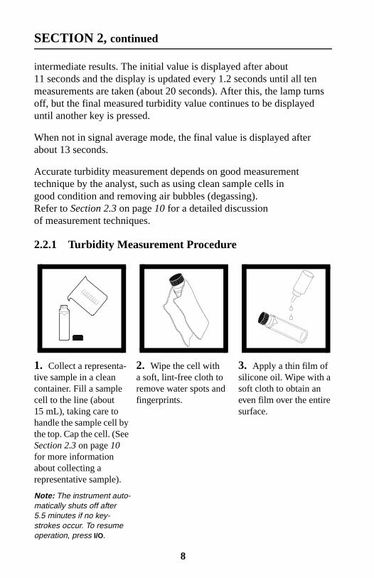
2.2.1 Turbidity Measurement Procedure
1. Collect a representa-tive sample in a cleancontainer. Fill a samplecell to the line (about15 mL), taking care tohandle the sample cell bythe top. Cap the cell. (SeeSection 2.3 on page 10for more informationabout collecting arepresentative sample).
Note: The instrument auto-matically shuts off after5.5 minutes if no key-strokes occur. To resumeoperation, press I/O.
2. Wipe the cell witha soft, lint-free cloth toremove water spots andfingerprints.
3. Apply a thin film ofsilicone oil. Wipe with asoft cloth to obtain aneven film over the entiresurface.
8
SECTION 2, continued
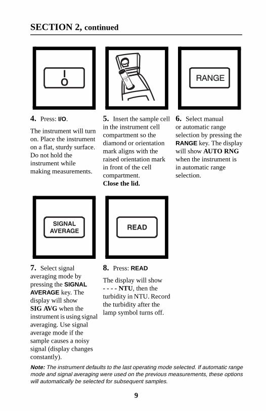
4. Press: I/O.
The instrument will turnon. Place the instrumenton a flat, sturdy surface.Do not hold theinstrument whilemaking measurements.
5. Insert the sample cellin the instrument cellcompartment so thediamond or orientationmark aligns with theraised orientation markin front of the cellcompartment.Close the lid.
6. Select manualor automatic rangeselection by pressing theRANGE key. The displaywill show AUTO RNGwhen the instrument isin automatic rangeselection.
7. Select signalaveraging mode bypressing the SIGNALAVERAGE key. Thedisplay will showSIG AVG when theinstrument is using signalaveraging. Use signalaverage mode if thesample causes a noisysignal (display changesconstantly).
8. Press: READ
The display will show- - - - NTU, then theturbidity in NTU. Recordthe turbidity after thelamp symbol turns off.
Note: The instrument defaults to the last operating mode selected. If automatic rangemode and signal averaging were used on the previous measurements, these optionswill automatically be selected for subsequent samples.
9

SECTION 2, continued
2.2.2 Measurement Notes
• Always cap the sample cell to prevent spillage of sample intothe instrument.
• When taking a reading, place the instrument on a level, stationarysurface. It should not be held in the hand during measurement.
• Always close the sample compartment lid during measurementand storage.
• Always use clean sample cells in good condition. Dirty, scratched,or damaged cells can cause inaccurate readings.
• Do not leave a sample cell in the cell compartment for extendedperiods of time. This may compress the spring in the cell holder.
• Remove sample cell and batteries from instrument if the instrumentis stored for extended time period (more than a month).
• Avoid operating in direct sunlight.
• Make certain cold samples do not “fog” the sample cell.
• Avoid settling of sample prior to measurement.
• Keep sample compartment lid closed to prevent dust and dirtfrom entering.
2.3 Measurement TechniquesProper measurement techniques are important in minimizingthe effects of instrument variation, stray light and air bubbles.Regardless of the instrument used, measurements are more accurate,precise and repeatable if the analyst pays close attention to propermeasurement techniques.
Measure samples immediately to prevent temperature changes andsettling. Avoid sample dilution when possible. Particles suspended inthe original sample may dissolve or otherwise change characteristicswhen the sample temperature changes or when the sample is diluted,resulting in a non-representative sample measurement.
10
SECTION 2, continued
2.3.1 Cleaning Sample CellsCells must be extremely clean and free from significant scratches. Theglass used to make cells is easily scratched – manufacturing cells free ofminor scratches and other imperfections is difficult. However, minorimperfections are effectively masked by applying silicone oil asoutlined in Section 2.3.2.
Clean the inside and outside of the cells by washing with laboratorydetergent. Follow with multiple rinses of distilled or deionized water.Allow cells to air dry. Handle cells only by the top to minimize dirt,scratches and fingerprints in the light path.
2.3.2 Oiling the Sample CellApplying a thin coat of silicone oil will mask minor imperfections andscratches which may contribute to turbidity or stray light. Use siliconeoil equivalent to Hach Cat. No. 1269-36. This silicone oil has the samerefractive index as glass. When applied in a thin, uniform coat, the oilfills in and masks minor scratches and other imperfections in the glass.Apply the oil uniformly by wiping with a soft, lint-free cloth.Avoid application of excess oil. Applying excess oil may retaindirt and contaminate the instrument's cell compartment.
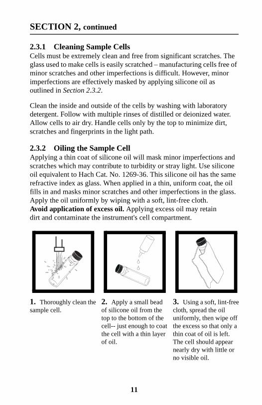
1. Thoroughly clean thesample cell.
2. Apply a small beadof silicone oil from thetop to the bottom of thecell-- just enough to coatthe cell with a thin layerof oil.
3. Using a soft, lint-freecloth, spread the oiluniformly, then wipe offthe excess so that only athin coat of oil is left.The cell should appearnearly dry with little orno visible oil.
11

SECTION 2, continued
Note: Soft, lint-free cloth (velvet) works well for oiling. Store the oiling cloth with thesample cells and keep it free of dirt. After a few applications of oil, the cloth willcontain enough residual oil that simply wiping the cell with the oiled cloth will providea sufficient oil coat on the sample cell. Periodically, add a small amount of oil to thesample cell surface to replenish the oil in the cloth.
Note: Only a thin coat of oil on the sample cells is necessary. Avoid usingexcessive amounts of oil.
2.3.3 Orienting Sample Cells
Note: When orienting and matching cells, it may be more efficient to use thecontinuous reading mode. The instrument performs continuous readings if theREAD key is pressed and held. As long as the key is held, the lamp remains onand the display is updated every 1.2 seconds. The instrument cannot be used incontinuous read mode if the Signal Averaging mode is on.
Precise measurements for very low turbidity samples require using asingle cell for all measurements or optically matching the cells. Usingone cell provides the best precision and repeatability. When one cell isused, an orientation mark (other than the factory-placed diamond) canbe placed on the cell so it’s inserted into the instrument with the sameorientation each time.
12

SECTION 2, continued
2.3.3.1 Orienting a single cellWhen using a single cell, make an index or orientation mark on the cellas follows:
1. Fill the clean samplecell to the line withhigh quality water(< 0.5 NTU). Cap andwipe with lint-free cloth.Apply silicone oil. SeeSection 3.6.2.2 onpage 30 for moreinformation abouthigh quality water.
2. Press: I/O to turn theinstrument on.
3. Insert the samplecell into the samplecompartment. Closethe cover.
13

SECTION 2, continued
14
4. Press: READ
Record the cell's positionin the cell compartmentand the displayedreading.
Note: This procedure maybe easier if the user holdsthe READ key through thewhole process. This allowsthe lamp to remain on andmake continuous readings.
5. Remove the cell,rotate it slightly andreinsert it into the cellcompartment. Close thecover, then press READ.Record the cell's positionand the displayedreading.
6. Repeat step 5 untilthe lowest reading isdisplayed. Place anorientation mark on thecell's marking band nearthe top of the cell so thecell can be consistentlyinserted in the positionthat yields the lowestreading. When using thecell, always place it inthe instrument so theorientation mark alignswith the raised mark onthe instrument.
SECTION 2, continued
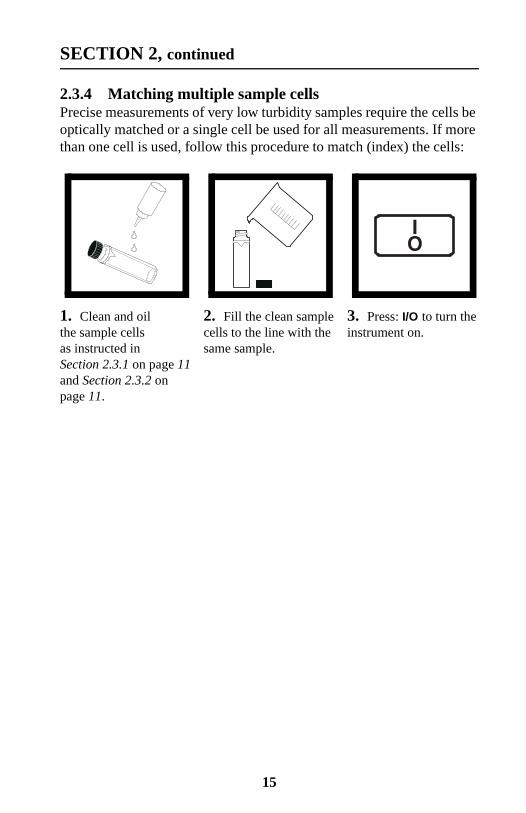
2.3.4 Matching multiple sample cellsPrecise measurements of very low turbidity samples require the cells beoptically matched or a single cell be used for all measurements. If morethan one cell is used, follow this procedure to match (index) the cells:
1. Clean and oilthe sample cellsas instructed inSection 2.3.1 on page 11and Section 2.3.2 onpage 11.
2. Fill the clean samplecells to the line with thesame sample.
3. Press: I/O to turn theinstrument on.
15
SECTION 2, continued
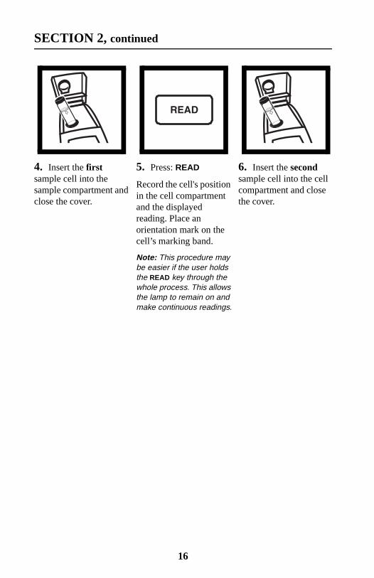
4. Insert the firstsample cell into thesample compartment andclose the cover.
5. Press: READ
Record the cell's positionin the cell compartmentand the displayedreading. Place anorientation mark on thecell’s marking band.
Note: This procedure maybe easier if the user holdsthe READ key through thewhole process. This allowsthe lamp to remain on andmake continuous readings.
6. Insert the secondsample cell into the cellcompartment and closethe cover.
16
SECTION 2, continued
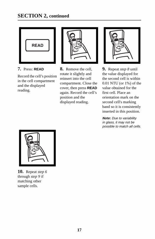
7. Press: READ
Record the cell’s positionin the cell compartmentand the displayedreading.
8. Remove the cell,rotate it slightly andreinsert into the cellcompartment. Close thecover, then press READagain. Record the cell’sposition and thedisplayed reading.
9. Repeat step 8 untilthe value displayed forthe second cell is within0.01 NTU (or 1%) of thevalue obtained for thefirst cell. Place anorientation mark on thesecond cell's markingband so it is consistentlyinserted in this position.
Note: Due to variabilityin glass, it may not bepossible to match all cells.
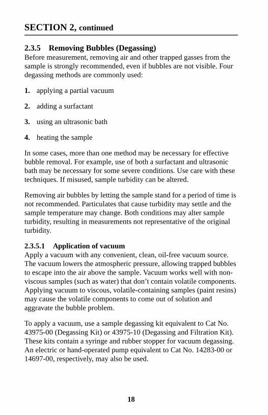
10. Repeat step 6through step 9 ifmatching othersample cells.
17
SECTION 2, continued
2.3.5 Removing Bubbles (Degassing)Before measurement, removing air and other trapped gasses from thesample is strongly recommended, even if bubbles are not visible. Fourdegassing methods are commonly used:
1. applying a partial vacuum
2. adding a surfactant
3. using an ultrasonic bath
4. heating the sample
In some cases, more than one method may be necessary for effectivebubble removal. For example, use of both a surfactant and ultrasonicbath may be necessary for some severe conditions. Use care with thesetechniques. If misused, sample turbidity can be altered.
Removing air bubbles by letting the sample stand for a period of time isnot recommended. Particulates that cause turbidity may settle and thesample temperature may change. Both conditions may alter sampleturbidity, resulting in measurements not representative of the originalturbidity.
2.3.5.1 Application of vacuumApply a vacuum with any convenient, clean, oil-free vacuum source.The vacuum lowers the atmospheric pressure, allowing trapped bubblesto escape into the air above the sample. Vacuum works well with non-viscous samples (such as water) that don’t contain volatile components.Applying vacuum to viscous, volatile-containing samples (paint resins)may cause the volatile components to come out of solution andaggravate the bubble problem.
To apply a vacuum, use a sample degassing kit equivalent to Cat No.43975-00 (Degassing Kit) or 43975-10 (Degassing and Filtration Kit).These kits contain a syringe and rubber stopper for vacuum degassing.An electric or hand-operated pump equivalent to Cat No. 14283-00 or14697-00, respectively, may also be used.
18

SECTION 2, continued
2.3.5.2 Adding a surfactantSurfactants should be limited to severe problems when other degassingmethods are ineffective. Surfactants change the surface tension of thewater, which releases trapped gases. Hach recommends a surfactantsuch as Triton X-100 or the equivalent, Hach Cat No. 14096-37. Put onedrop of Triton X-100 in the sample cell before adding sample.
Note: Any turbidity contributed by surfactant addition is negligible.
This technique is very effective when the water is super-saturated withair. However, changing the surface tension may accelerate settling ofturbidity-causing particles. Mix the sample gently, but thoroughly, andanalyze as soon as possible after adding the surfactant. Avoid vigorousmixing as the surfactant may foam. Rinse the sample cells thoroughlybetween samples to prevent surfactant accumulation.
1. Fill a sample cell tothe mark with sample.Insert a #2 single-holerubber stopper andsyringe into the cell.If using a pump, inserta piece of glass tubinginto the stopper.
2. Slowly apply thevacuum by carefullypulling the plungerupward, then holding it.If using a hand or electricpump, connect the tubingto the vacuum pump withvacuum hose. Applyvacuum until visible gasbubbles disappear.Slowly release thevacuum. Remove thevacuum apparatus andcap the cell.
19
SECTION 2, continued
2.3.5.3 Using an ultrasonic bath
Note: The time necessary to expel bubbles may vary from a few seconds to aminute or more. To avoid excessive application of ultrasound, a simpleprocedure can be followed. First, apply ultrasound until all visible bubblesare absent. Then measure the sample turbidity. Apply ultrasound for ashort time period and again measure turbidity. Continue for severalrepetitions, noting the treatment time and turbidity readings. If turbiditybegins to increase instead of decrease, the ultrasound waves haveprobably started to alter the suspended particles. Note the time ittakes for this to occur and record it as the maximum time limit forultrasonic treatment.
Ultrasonic baths effectively remove gas bubbles from most samples,especially viscous liquids. However, the ultrasonic waves which causedegassing may also alter the characteristics of the particles causing theturbidity. Turbidity depends on the size, shape, composition andrefractive index of the suspended particles. Excessive ultrasoundapplication may alter particle size and shape, thus changing sampleturbidity. In some cases, ultrasound may aggravate air bubble removalby fracturing the bubbles, making degassing more difficult.
1. Fill a clean sample cell to the line with sample. Leave uncapped.
2. Immerse the cell (1/2 to 2/3 immersed) in an ultrasonic bath andallow it to stand until visible bubbles are expelled.
3. Remove the cell, cap, then thoroughly dry the cell. Apply siliconeoil as directed.
2.3.5.4 Application of heatWhenever possible, avoid using heat to degas samples because heat maychange the characteristics of the suspended particles and cause volatilecomponents to come out of solution. Gentle heating may be helpful fordegassing some very viscous samples when combined with applicationof vacuum or ultrasound. If heat is necessary, heat the sample only untildegassing occurs. The simplest technique is to prepare a warm waterbath and partially immerse the filled sample cell. Use the shortest timenecessary for expelling visible bubbles. Cool sample to original sampletemperature before taking measurements.
20

SECTION 2, continued
2.3.6 Measuring Overrange SamplesNephelometric turbidity measurement depends on detection of lightscattered from particles suspended in the liquid. If the turbidity is veryhigh, a significant amount of light is blocked or absorbed by theparticles and only a small amount of light reaches the detector.This results in a negative interference – the measured turbidity islower than the actual turbidity. This condition is called “going blind”.A multidetector ratioing instrument, such as the Hach 2100PTurbidimeter, minimizes this effect and extends the instrument range.Highly turbid samples may also be diluted, but this should be avoidedwhen possible since it may alter the characteristics of the suspendedparticles and produce erroneous results.
Light absorbing particles such as activated carbon and highly coloredsamples may also cause an instrument to “go blind”. Dilution may notcorrect for these interferences. A ratioing instrument will correct for thepresence of light absorbing particles and color.
2.3.7 Condensation (fogging)Condensation may occur on the outside of the sample cellwhen measuring a cold sample in a warm, humid environment.Condensation interferes with turbidity measurement, so all moisturemust be thoroughly wiped off the sample cell before measurement.If fogging recurs, let the sample warm slightly by standing at roomtemperature or immersing it in a warm bath for a short period. Afterwarming, mix the sample thoroughly before measurement. Allowingsamples to warm can alter sample turbidity, so it is best to avoidwarming samples before measurement when possible.
2.3.8 CalibrationTurbidimeters must be properly calibrated with a primary standard.Hach recommends formazin or StablCal Stabilized Formazin forcalibration. For U.S. Environmental Protection Agency (USEPA)reporting, calibrate at least as often as required by the appropriateregulatory agencies. The frequency of calibration depends onenvironmental conditions (humidity, temperature) and use. If necessary,calibrate more frequently.
21

SECTION 2, continued
Use secondary standards for periodic calibration checks. Please notethat Gelex® standards must be assigned values after StablCal StabilizedFormazin calibration or formazin calibration and before use assecondary standards. Gelex standards must be recalibrated (valuesassigned) each time the instrument is calibrated with StablCalStabilized Formazin or formazin. See Section 3.6 on page 27 fordetailed information on the use of StablCal Stabilized Formazin,formazin, and Gelex standards.
2.3.9 Representative SamplingA representative sample accurately reflects the true condition ofthe water source from which the sample was taken. To ensure arepresentative sample, gently, but thoroughly, mix every samplebefore aliquots are taken. Do not allow the sample to settle.
When sampling from a tap in a distribution system or treatment plant,allow the water to run for at least five minutes before sampling.When sampling from a stream, reservoir, clarifier, or storage tank,collect at least one liter (l quart) and thoroughly mix beforemeasurement. If the water source is not uniform, it may be necessaryto sample several locations at varying depths and combine the samplesinto a single, well-mixed composite sample before measurement.
22

SECTION 3 OPERATION
3.1 Operational Controls and Indicators
Key Description
Power key to turn instrument on and off. If no keys are pressedfor 5.5 minutes, the instrument turns off automatically.
Depressed to perform a measurement. To conserve batterypower, the lamp turns on only when READ is depressed.A reading is displayed about 12 seconds after the key isdepressed. During the delay, a flashing NTU is displayed.After the reading is displayed, the lamp turns off and thereading continues to be displayed. Continuous readings maybe done by holding this key if not in the Signal Averagingmode. After the initial delay, the reading is updated every1.2 seconds.
Used to perform a calibration or review calibration data. Alsoterminates a calibration or calibration review and returns to the2100P measurement mode.
23
SECTION 3, continued
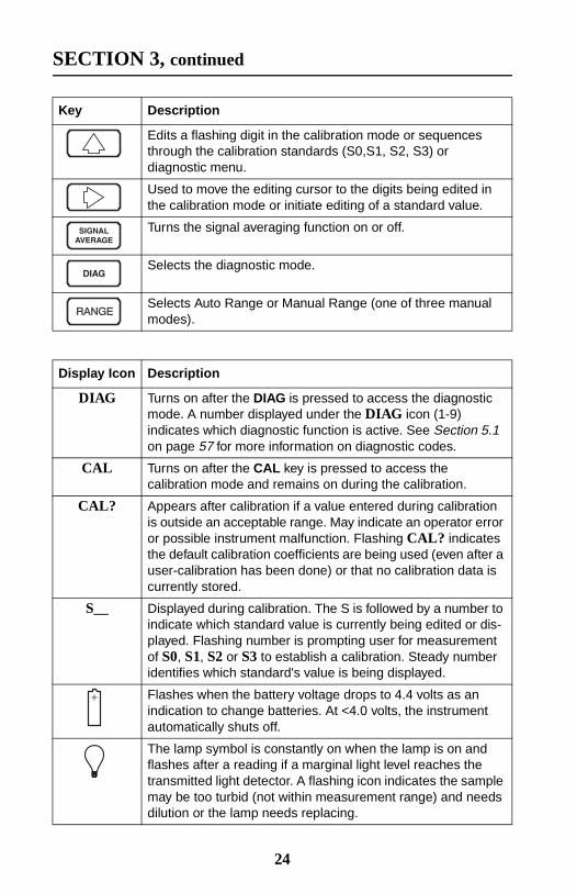
Edits a flashing digit in the calibration mode or sequencesthrough the calibration standards (S0,S1, S2, S3) ordiagnostic menu.
Used to move the editing cursor to the digits being edited inthe calibration mode or initiate editing of a standard value.
Turns the signal averaging function on or off.
Selects the diagnostic mode.
Selects Auto Range or Manual Range (one of three manualmodes).
Display Icon Description
DIAG Turns on after the DIAG is pressed to access the diagnosticmode. A number displayed under the DIAG icon (1-9)indicates which diagnostic function is active. See Section 5.1on page 57 for more information on diagnostic codes.
CAL Turns on after the CAL key is pressed to access thecalibration mode and remains on during the calibration.
CAL? Appears after calibration if a value entered during calibrationis outside an acceptable range. May indicate an operator erroror possible instrument malfunction. Flashing CAL? indicatesthe default calibration coefficients are being used (even after auser-calibration has been done) or that no calibration data iscurrently stored.
S__ Displayed during calibration. The S is followed by a number toindicate which standard value is currently being edited or dis-played. Flashing number is prompting user for measurementof S0, S1, S2 or S3 to establish a calibration. Steady numberidentifies which standard's value is being displayed.
Flashes when the battery voltage drops to 4.4 volts as anindication to change batteries. At <4.0 volts, the instrumentautomatically shuts off.
The lamp symbol is constantly on when the lamp is on andflashes after a reading if a marginal light level reaches thetransmitted light detector. A flashing icon indicates the samplemay be too turbid (not within measurement range) and needsdilution or the lamp needs replacing.
Key Description
24
SECTION 3, continued
25
3.2 Using the Read KeyTo preserve battery power and prolong lamp life, the lamp turns on onlyafter the READ key is pressed. Pressing the key turns the instrumentlamp on; after about 12 seconds, the lamp turns off, but themeasurement value continues to be displayed. After the firstmeasurement, a four-second recovery time occurs before anothermeasurement can be started. If READ is pressed during the recoverytime, the display will begin flashing, but the lamp will not turn on untilthe full four seconds have passed. If no other key strokes occur within5.5 minutes, the instrument turns off.
3.2.1 Continuous ReadingThe instrument cannot be used in continuous read mode if the SignalAveraging mode is on.
The instrument will perform continuous readings if the READ key ispressed and held. As long as the key is held, the lamp remains on andthe display is updated every 1.2 seconds.
3.3 Using the Signal Averaging KeyThe signal averaging mode compensates for reading fluctuations causedby drifting of sample particles through the light path. Signal averagingis turned on or off by pressing the SIGNAL AVERAGE key. The SIG AVGicon is displayed when signal averaging is on.
Signal averaging measures and averages ten measurements whiledisplaying intermediate results. The initial value is displayed after about
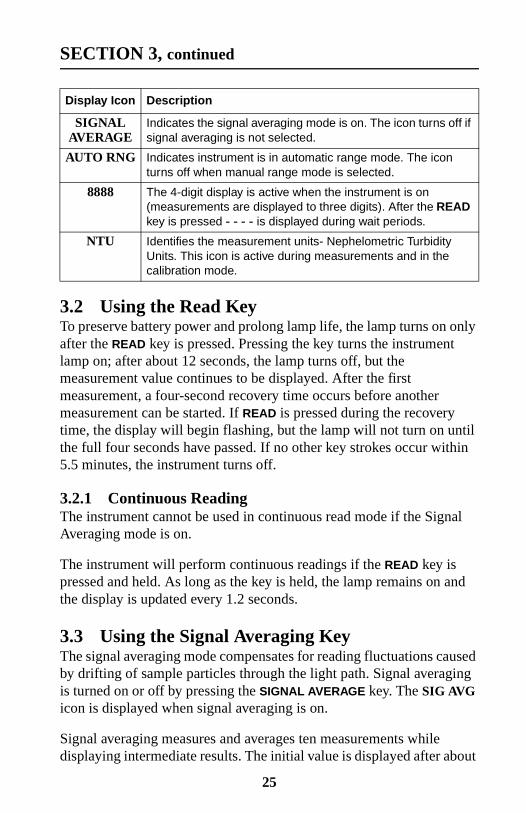
SIGNALAVERAGE
Indicates the signal averaging mode is on. The icon turns off ifsignal averaging is not selected.
AUTO RNG Indicates instrument is in automatic range mode. The iconturns off when manual range mode is selected.
8888 The 4-digit display is active when the instrument is on(measurements are displayed to three digits). After the READkey is pressed - - - - is displayed during wait periods.
NTU Identifies the measurement units- Nephelometric TurbidityUnits. This icon is active during measurements and in thecalibration mode.
Display Icon Description

SECTION 3, continued
11 seconds and the display is updated every 1.2 seconds until all tenmeasurements are taken (about 22 seconds). After 22 seconds, the lampturns off, but the final measured turbidity value continues to bedisplayed until another key is pressed.
When signal averaging is off, the instrument takes three measurements,the microprocessor averages them, then displays the average. If theREAD key is held during measurement, the initial value is displayedin 12 seconds and is updated every 1.2 seconds as long as the READkey is held.
When the instrument is turned on, the instrument defaults to the signalaveraging mode which was used during the last measurement.
3.4 Using the Range Selection KeyAs shipped, the instrument defaults to automatic range mode. The firsttime the RANGE key is pressed, the instrument goes into manual rangemode. The second, third, and fourth key strokes put the instrument inthe 0.00-9.99, 10 to 99.9 or 100-1000 NTU range, respectively. Anotherkey stroke brings the selection back to automatic range mode. When theautomatic range mode is selected, the AUTO RNG icon is displayed.Range selection can be done any time except when a measurement orcalibration is in progress.
When the instrument is turned on, the instrument defaults to the rangemode and measurement range which was used during the lastmeasurement.
3.5 Restoring the Default CalibrationTo restore and use the default calibration, turn the instrument off.Press and hold DIAG, then press and release I/O. Release DIAG when thesoftware version number disappears from the display. (For models withserial number less than 920300000800, 2100 disappears). This clearsany user-entered calibration from memory; the 2100P will use thedefault calibration for measurement. CAL? will appear and continue toflash until a user-entered calibration is successfully completed.
For best results, a user-entered calibration should be done every threemonths.
26
SECTION 3, continued
3.6 CalibrationCalibration of the 2100P Turbidimeter is based on formazin, theprimary standard for turbidity. The instrument's electronic and opticaldesign provide long-term stability and minimize the need for frequentcalibration. The two-detector ratioing system compensates for mostfluctuations in lamp output. A formazin recalibration should beperformed at least once every three months, more often if experienceindicates the need. When calibration is necessary, use a primarystandard such as StablCal™ Stabilized Standards or formazinstandards.
Hach Company only recommends the use of StablCal® StabilizedFormazin or formazin standards for the calibration of Hachturbidimeters. Hach Company cannot guarantee the performanceof the turbidimeter if calibrated with co-polymer styrenedivinylbenzene beads or other suspensions.
3.6.1 StablCal Stabilized Formazin Standards*Most consistent results will be achieved with the use of StablCalStabilized Formazin Standards for calibration. Refer to Section 3.6.1.2and Section 3.6.1.3 for information on preparing the standards for use.
Note: Hach StablCal Stabilized Formazin in 20-, 100-, and 800-NTU values ispackaged in convenient sets for calibration of the 2100P Turbidimeter. The setmay be ordered in 500-mL size bottles by specifying Cat. No. 26594-00, in100-mL size bottles by specifying Cat. No. 26594-10 or in sealed vials byordering Cat. No. 26594-05. (See OPTIONAL ACCESSORIES ANDREAGENTS on page 61.)
3.6.1.1 Storing and Handling StablCal Stabilized StandardsFor optimum results when using StablCal Stabilized Standards, adhereto the following recommendations:
• Do not transfer the standard to another container for storage.
• Do not return standard from the sample cell back into the itsoriginal container. Standard contamination will result.
• Store standards between 0 and 25 °C.
* StablCal Stabilized Formazin is cited as a primary standard in HachMethod 8195, an acceptable version of USEPA Method 180.1.
27
SECTION 3, continued
• For long-term storage, refrigeration at 5 °c is recommended. Do notstore above 25 °C.
• Allow the standard to acclimate to ambient instrument conditionsbefore use (not to exceed 40 °C).
• Store away from direct sunlight. Store vials in their respective kit orshipping box with the cover in place.
3.6.1.2 Preparing Bulk StablCal Stabilized StandardsBulk standards that have been sitting undisturbed for longer than amonth must be shaken to break the condensed suspension into itsoriginal particle size. Start at step 1 for these standards. If the standardsare used on at least a weekly interval, start at step 3.
Important Note: These instructions do not apply to <0.1-NTU* StablCalStandards; <0.1NTU StablCal Standards should not be shaken or inverted.
1. Shake the standard vigorously for 2-3 minutes to resuspendany particles.
2. Allow the standard to stand undisturbed for 5 minutes.
3. Gently invert the bottle of StablCal 5 to 7 times.
4. Prepare the sample cell for measurement using traditionalpreparation techniques. This usually consists of oiling the samplecell (seeSection 2.3.2 on page 11) and marking the cell to maintainthe same orientation in the sample cell compartment (seeSection 2.3.3 on page 12). This step will eliminate any opticalvariations in the sample cell.
5. Rinse the sample cell at least one time with the standard and discardthe rinse.
6. Immediately fill the sample cell with the standard. Cap the samplecell and let it stand for one minute. The standard is now ready foruse in the calibration procedure, Section 3.6.3.
* Used in place of the dilution water standard when performing acalibration.
28
SECTION 3, continued
3.6.1.3 Preparing StablCal Stabilized Standards in Sealed VialsSealed vials that have been sitting undisturbed for longer than a monthmust be shaken to break the condensed suspension into its originalparticle size. Start at step 1 for these standards. If the standards are usedon at least a weekly interval, start at step 3
Important Note: These instructions do not apply to <0.1-NTU* StablCalStandards; <0.1NTU StablCal Standards should not be shaken or inverted.
1. Shake the standard vigorously for 2-3 minutes to resuspendany particles.
2. Allow the standard to stand undisturbed for 5 minutes.
3. Gently invert the vial of StablCal 5 to 7 times.
4. Prepare the vial for measurement using traditional preparationtechniques. This usually consists of oiling the vial (seeSection 2.3.2 on page 11) and marking the vial to maintain the sameorientation in the sample cell compartment (see Section 2.3.3 onpage 12). This step will eliminate any optical variations in thesample vial.
5. Let the vial stand for one minute. The standard is now ready for usein the calibration procedure, Section 3.6.3.
3.6.2 Formazin Primary StandardsPerform the procedure in Section 3.6.2.1 to prepare a 4000-NTUstandard. Alternately, order a 4000-NTU stock solution from Hach byspecifying Cat. 2461-49. Prepare the dilutions from the 4000-NTUstock solution by following the instructions in Section 3.6.2.4.
29
SECTION 3, continued
3.6.2.1 Preparing Formazin Stock SolutionDilute formazin standard solutions from a 4000 NTU stock solutionequivalent to Hach Cat. No. 2461-49. The prepared stock solution isstable for up to one year when properly prepared. An alternative topurchasing the 4000 NTU stock solution is preparing a stock solutionas follows:
1. Dissolve 5.000 grams of reagent grade hydrazine sulfate(N2H4•H2SO4) in 400 mL of distilled water.
2. Dissolve 50.000 grams of pure hexamethylenetetramine in 400 mLof distilled water.
3. Pour the two solutions into a 1000-mL volumetric flask and diluteto the mark with distilled water.
4. Let the solution stand for 48 hours at 25 °C (77 °F) to develop the4000-NTU stock suspension. The standing temperature is criticalfor correct formation of formazin polymers.
5. Mix the 4000 NTU suspension for at least ten minutes before use.Then it can be diluted with distilled or demineralized water toachieve a solution of the desired NTU value.
Instead of diluting a formazin stock solution, StablCal StabilizedFormazin Standards may be used. Order the StablCal Calibration Setfor the 2100P Turbidimeter, Cat.No. 26594-00 (500-mL bottles),Cat. No. 26594-10 (100 mL bottles), or Cat. No. 26594-05 (sealedvials). (See OPTIONAL ACCESSORIES AND REAGENTS on page 61.)
3.6.2.2 Correcting for Turbidity of Dilution WaterThe 2100P Turbidimeter automatically compensates for turbiditycontributed by dilution water when calculating the true value of thelowest formazin standard. Use high quality distilled or deionized waterless than 0.5 NTU. The instrument will display E 1 after calibration ifthe dilution water turbidity is greater than 0.5 NTU. In this case, preparethe water as directed below.
30

SECTION 3, continued
The value of the dilution water can be arbitrarily forced to zero (seecalibration procedure). This is not recommended for most applicationsand, if done, should be done only if the dilution water turbidity is lessthan 0.2 NTU.
3.6.2.3 Preparing Dilution Water
Note: Use the same dilution water for all dilutions and the sample blank.
Collect at least 1000 mL of high quality dilution water (distilled ordeionized water). The 2100P Turbidimeter, as received from the factory,is precalibrated and may be used to check the dilution water turbidity. Ifthe turbidity is greater than 0.5 NTU, filter the water with the SampleFiltration and Degassing Kit (Cat. No. 43975-10) or equivalent. Whenmeasuring low range turbidity, clean all glassware with 1:1hydrochloric acid and rinse several times with dilution water. If theglassware is not used immediately, use stoppers to preventcontamination from small particles.
31

SECTION 3, continued
3.6.2.4 Preparing Formazin Dilutions (Factory recommended)Hach Company recommends using 20, 100, and 800 NTU formazinstandards for calibrating the 2100P Turbidimeter. Dilutions with otherNTU values can be prepared and used (see Section 3.6.3.1 on page 38).If problems occur when using alternate solutions, use the dilutionsspecified here.
Prepare all formazin dilutions immediately before use and discard aftercalibration. The 4000 NTU solution is stable for up to a year, butdilutions deteriorate more rapidly. Use the same high quality water(turbidity <0.5 NTU) for the dilutions and the blank.
1. Attach the syringeto the 3-way valve bygently twisting thesquare end into thesyringe tip. Attach theconnector, tubing and a0.2 micron filter (clearpart faces syringe) asshown. Be sure theconnections are tight.
2. Fill a beaker orcontainer with the waterto be filtered. Insert thetubing into the container.Slowly draw the waterinto the syringe bypulling up on thesyringe plunger.
3. Draw about 50 mL ofsample into the syringe.Slowly push on theplunger to force thewater through the filterand into a graduatedcylinder or volumetricflask. Repeat Steps 2and 3 until the desiredamount of water isobtained.
Note: As the filter clogs, itgets more difficult to pushwater through it. At thispoint, discard the filterand attach a new filter.Replacement filters areavailable in packages of 10(Cat. No. 23238-10).
32
SECTION 3, continued
Preparing the 20, 100 and 800 NTU standards
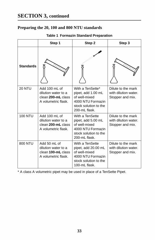
Table 1 Formazin Standard Preparation
Step 1 Step 2 Step 3
Standards
20 NTU Add 100 mL ofdilution water to aclean 200-mL classA volumetric flask.
With a TenSette*pipet, add 1.00 mLof well-mixed4000 NTU Formazinstock solution to the200-mL flask.
* A class A volumetric pipet may be used in place of a TenSette Pipet.
Dilute to the markwith dilution water.Stopper and mix.
100 NTU Add 100 mL ofdilution water to aclean 200-mL classA volumetric flask.
With a TenSettepipet, add 5.00 mLof well-mixed4000 NTU Formazinstock solution to the200-mL flask.
Dilute to the markwith dilution water.Stopper and mix.
800 NTU Add 50 mL ofdilution water to aclean 100-mL classA volumetric flask.
With a TenSettepipet, add 20.00 mLof well-mixed4000 NTU Formazinstock solution to the100-mL flask.
Dilute to the markwith dilution water.Stopper and mix.
33

SECTION 3, continued
3.6.3 Calibrating the Turbidimeter
Note: For best accuracy use the same sample cell or four matched samplecells for all measurements during calibration. Always insert the cell sothe orientation mark placed on the cell during the matching procedureis correctly aligned. (See Section 2.3.4 on page 15 for matchingsample cells).*
1. Rinse a clean samplecell with dilution waterseveral times. Then fillthe cell to the line (about15 mL) with dilutionwater or use StablCal<0.1 NTU standard.
Note: The same dilutionwater used for preparingthe standards must beused in this step.
2. Insert the sample cellin the cell compartmentby aligning theorientation mark onthe cell with the markon the front of the cellcompartment. Close thelid. Press I/O.
Note: Choose signalaverage mode option(on or off) before pressingCAL – the SIGNALAVERAGE key is notfunctional in calibrationmode.
3. Press: CAL
The CAL and S0 iconswill be displayed (the 0will flash). The 4-digitdisplay will show thevalue of the S0 standardfor the previouscalibration. If the blankvalue was forced to 0.0,the display will be blank(as shown). Press →toget a numerical display.
Hach Company only recommends the use of StablCal®Stabilized Formazin or formazin standards for thecalibration of Hach turbidimeters. Hach Companycannot guarantee the performance of the turbidimeterif calibrated with co-polymer styrene divinylbenzenebeads or other suspensions.
34
SECTION 3, continued
*
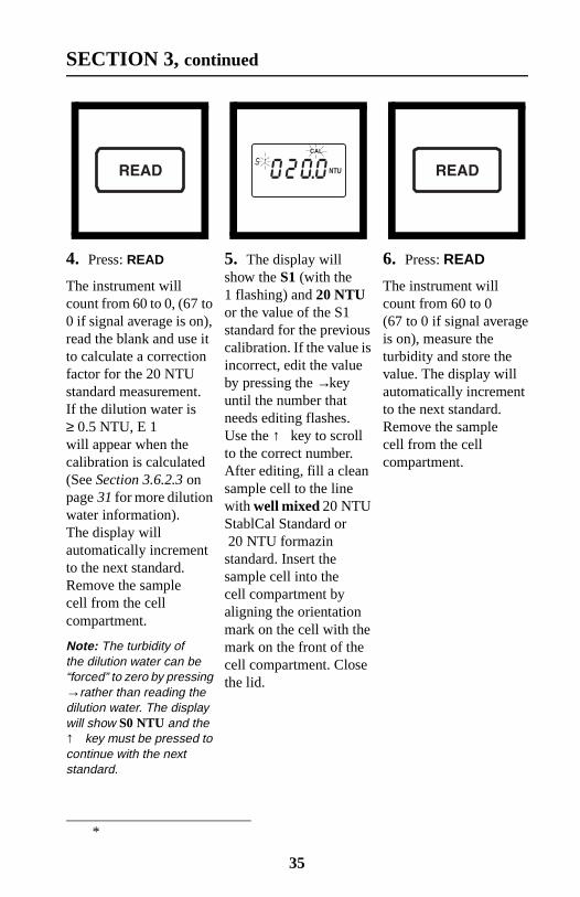
4. Press: READ
The instrument willcount from 60 to 0, (67 to0 if signal average is on),read the blank and use itto calculate a correctionfactor for the 20 NTUstandard measurement.If the dilution water is≥ 0.5 NTU, E 1will appear when thecalibration is calculated(See Section 3.6.2.3 onpage 31 for more dilutionwater information).The display willautomatically incrementto the next standard.Remove the samplecell from the cellcompartment.
Note: The turbidity ofthe dilution water can be“forced” to zero by pressing→ rather than reading thedilution water. The displaywill show S0 NTU and the↑ key must be pressed tocontinue with the nextstandard.
5. The display willshow the S1 (with the1 flashing) and 20 NTUor the value of the S1standard for the previouscalibration. If the value isincorrect, edit the valueby pressing the →keyuntil the number thatneeds editing flashes.Use the ↑ key to scrollto the correct number.After editing, fill a cleansample cell to the linewith well mixed 20 NTUStablCal Standard or20 NTU formazin
standard. Insert thesample cell into thecell compartment byaligning the orientationmark on the cell with themark on the front of thecell compartment. Closethe lid.
6. Press: READ
The instrument willcount from 60 to 0(67 to 0 if signal averageis on), measure theturbidity and store thevalue. The display willautomatically incrementto the next standard.Remove the samplecell from the cellcompartment.
35
SECTION 3, continued
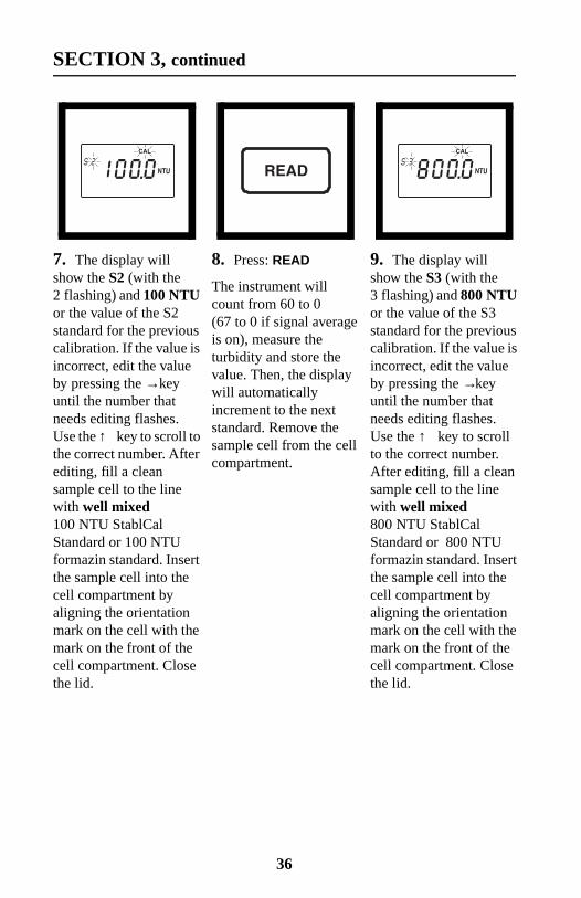
7. The display willshow the S2 (with the2 flashing) and 100 NTUor the value of the S2standard for the previouscalibration. If the value isincorrect, edit the valueby pressing the → keyuntil the number thatneeds editing flashes.Use the ↑ key to scroll tothe correct number. Afterediting, fill a cleansample cell to the linewith well mixed100 NTU StablCalStandard or 100 NTUformazin standard. Insertthe sample cell into thecell compartment byaligning the orientationmark on the cell with themark on the front of thecell compartment. Closethe lid.
8. Press: READ
The instrument willcount from 60 to 0(67 to 0 if signal averageis on), measure theturbidity and store thevalue. Then, the displaywill automaticallyincrement to the nextstandard. Remove thesample cell from the cellcompartment.
9. The display willshow the S3 (with the3 flashing) and 800 NTUor the value of the S3standard for the previouscalibration. If the value isincorrect, edit the valueby pressing the →keyuntil the number thatneeds editing flashes.Use the ↑ key to scrollto the correct number.After editing, fill a cleansample cell to the linewith well mixed800 NTU StablCalStandard or 800 NTUformazin standard. Insertthe sample cell into thecell compartment byaligning the orientationmark on the cell with themark on the front of thecell compartment. Closethe lid.
36

SECTION 3, continued
10. Press: READ
The instrument willcount from 60 to 0(67 to 0 if signal averageis on), measure theturbidity and store thevalue. Then the displaywill increment back tothe S0 display. Removethe sample cell from thecell compartment.
11. Press: CAL toaccept the calibration.The instrument willreturn to measurementmode automatically.
Note: Pressing CALcompletes the calculationof the calibrationcoefficients. If calibrationerrors occurred duringcalibration, error messageswill appear after CAL ispressed. If E 1 or E 2appear, check the standardpreparation and review thecalibration; repeat thecalibration if necessary. IfCAL? appears, an errormay have occurred duringcalibration. If CAL? isflashing, the instrumentis using the defaultcalibration.
37
SECTION 3, continued
NOTES
• If the I/O key is pressed during calibration, the new calibration datais lost and the old calibration will be used for measurements. Oncein calibration mode, only the READ, I/O, ↑ , and →keys function.Signal averaging and range mode must be selected before enteringthe calibration mode.
• If E 1 or E 2 are displayed, an error occurred during calibration.Check the standard preparation and review the calibration; repeatthe calibration if necessary. Press DIAG to cancel the error message(E 1 or E 2). To continue without repeating the calibration, press I/Otwice to restore the previous calibration. If CAL? is displayed, anerror may have occurred during calibration. The previouscalibration may not be restored. Either recalibrate or use thecalibration as is.
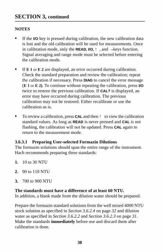
• To review a calibration, press CAL and then ↑ to view the calibrationstandard values. As long as READ is never pressed and CAL is notflashing, the calibration will not be updated. Press CAL again toreturn to the measurement mode.
3.6.3.1 Preparing User-selected Formazin DilutionsThe formazin solutions should span the entire range of the instrument.Hach recommends preparing three standards:
1. 10 to 30 NTU
2. 90 to 110 NTU
3. 700 to 900 NTU
The standards must have a difference of at least 60 NTU.In addition, a blank made from the dilution water should be prepared.
Prepare the formazin standard solutions from the well mixed 4000 NTUstock solution as specified in Section 3.6.2.4 on page 32 and dilutionwater as specified in Section 3.6.2.2 and Section 3.6.2.3 on page 31.Make the standards immediately before use and discard them aftercalibration is done.
38
SECTION 3, continued
3.6.3.2 Calibrating with User-selected Standards
Note: For best accuracy use the same sample cell or four matched sample cellsfor all measurements during calibration. Always insert the sample cell withthe same orientation.
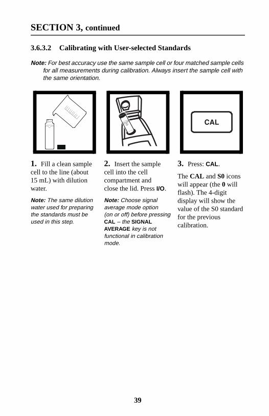
1. Fill a clean samplecell to the line (about15 mL) with dilutionwater.
Note: The same dilutionwater used for preparingthe standards must beused in this step.
2. Insert the samplecell into the cellcompartment andclose the lid. Press I/O.
Note: Choose signalaverage mode option(on or off) before pressingCAL – the SIGNALAVERAGE key is notfunctional in calibrationmode.
3. Press: CAL.
The CAL and S0 iconswill appear (the 0 willflash). The 4-digitdisplay will show thevalue of the S0 standardfor the previouscalibration.
39
SECTION 3, continued
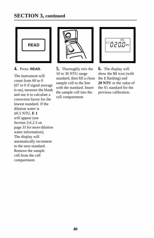
4. Press: READ.
The instrument willcount from 60 to 0(67 to 0 if signal averageis on), measure the blankand use it to calculate acorrection factor for thelowest standard. If thedilution water is≥0.5 NTU, E 1will appear (seeSection 3.6.2.3 onpage 31 for more dilutionwater information).The display willautomatically incrementto the next standard.Remove the samplecell from the cellcompartment.
5. Thoroughly mix the10 to 30 NTU rangestandard, then fill a cleansample cell to the linewith the standard. Insertthe sample cell into thecell compartment
6. The display willshow the S1 icon (withthe 1 flashing) and20 NTU or the value ofthe S1 standard for theprevious calibration.
40

SECTION 3, continued
7. Edit the standardconcentration bypressing →. The 1 willstop flashing and the leftdigit in the display willflash. Press ↑ to scrollthe digit up to theappropriate number.Press → again to movethe cursor to the nextdigit and edit it in thesame manner.
8. When all the digitsshow the appropriatevalue, press READ.The instrument willcount from 60 to 0(67 to 0 if signal averageis on), measure theturbidity and store thevalue. The display willautomatically incrementto the next standard.Remove the samplecell from the cellcompartment.
9. Thoroughly mix the90 to 110 NTU standard,then fill a clean samplecell to the line with thestandard. Insert thecell into the cellcompartment.
41

SECTION 3, continued
10. The display willshow the S2 icon (withthe 2 flashing) and100 NTU or the valueof the S2 standard for theprevious calibration.
11. Edit the standardconcentration bypressing →. The 2 willstop flashing and the leftdigit in the display willflash.Press↑ toscroll thedigit up to theappropriate number.Press → again to movethe cursor to the nextdigit and edit it in thesame manner.
12. When all the digitsshow the appropriatevalue, press READ.The instrument willcount from 60 to 0(67 to 0 if signal averageis on), measure theturbidity and store thevalue. Remove thesample cell from thecell compartment.
13. Thoroughly mix the700 to 900 NTUstandard, then fill a cleansample cell to the linewith the standard. Insertthe cell into the cellcompartment.
14. The display willshow the S3 icon (withthe 3 flashing) and800 NTU or the valueof the S3 standard for theprevious
15. Edit the standardconcentration bypressing →. The 3 willstop flashing and the leftdigit in the display willflash.Press↑ toscroll thedigit up to theappropriate number.Press → again to movethe cursor to the nextdigit and edit it in thesame manner.
42
SECTION 3, continued
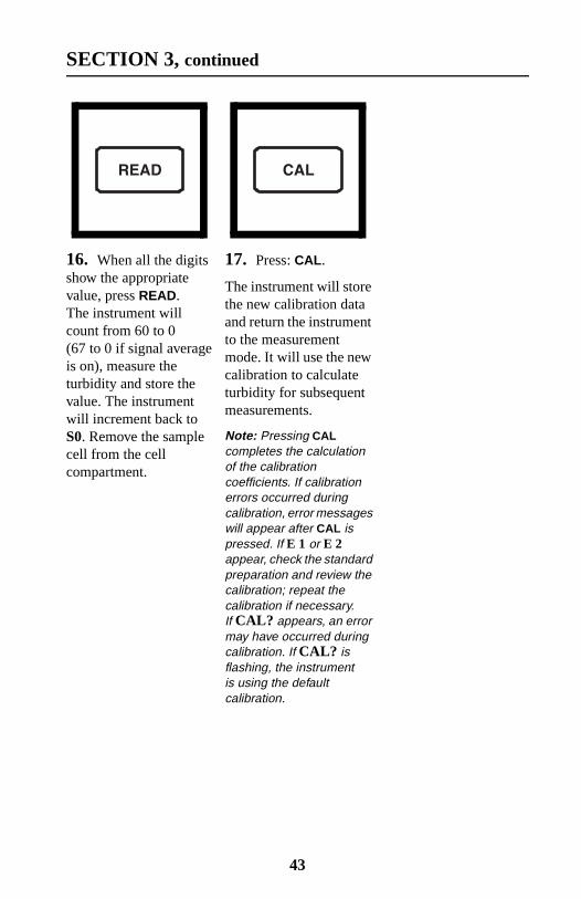
16. When all the digitsshow the appropriatevalue, press READ.The instrument willcount from 60 to 0(67 to 0 if signal averageis on), measure theturbidity and store thevalue. The instrumentwill increment back toS0. Remove the samplecell from the cellcompartment.
17. Press: CAL.
The instrument will storethe new calibration dataand return the instrumentto the measurementmode. It will use the newcalibration to calculateturbidity for subsequentmeasurements.
Note: Pressing CALcompletes the calculationof the calibrationcoefficients. If calibrationerrors occurred duringcalibration, error messageswill appear after CAL ispressed. If E 1 or E 2appear, check the standardpreparation and review thecalibration; repeat thecalibration if necessary.If CAL? appears, an errormay have occurred duringcalibration. If CAL? isflashing, the instrumentis using the defaultcalibration.
43
SECTION 3, continued
NOTES
• If the I/O key is pressed during calibration, the new calibration datais lost and the old calibration will be used for measurements. Oncein calibration mode, only the READ, I/O, ↑ , and →keys function.Signal averaging and range mode must be selected before enteringthe calibration mode.
• If E 1 or E 2 are displayed, an error occurred during calibration.Check the standard preparation and review the calibration; repeatthe calibration if necessary. If the error messages recur, calibrateusing the factory specified standards, Section 3.6.2.4 on page 32and Section 3.6.3 on page 34. Press DIAG to cancel the errormessage (E 1 or E 2). To continue without repeating the calibration,press I/O twice to restore the previous calibration. If CAL? isdisplayed, an error may have occurred during calibration. Theprevious calibration may not be restored. Either recalibrate or usethe calibration as is.
• To review a calibration, press CAL and then only ↑ to view thecalibration standard values. As long as READ is never pressed andCAL isn’t flashing, the calibration will not be updated. Press CALagain to return to the measurement mode.
3.6.4 Using Gelex® Secondary Turbidity Standards
Note: Store Gelex standards at room temperature. Do not allow to freeze orexceed 50 °C.
The instrument comes with Gelex Secondary Standards which areparticulate suspensions similar to formazin primary standards in lightscattering characteristics. NTU values on the Gelex standards indicatethe range for which they should be used. Due to minor variations inglass and individual instrument optical systems, the true value of theGelex standards must be determined against formazin in the sameinstrument they will be used with for later calibration checks.
44

SECTION 3, continued
3.6.4.1 Assigning Values to Gelex Standards
1. Calibrate theinstrument withformazin.
2. Select automaticrange mode using theRANGE key.
3. Thoroughly clean theoutside of the Gelex vialsand apply a thin coatingof silicone oil.
4. Place the 0-10 NTUGelex standard in the cellcompartment so thediamond on the vialaligns with theorientation mark onthe instrument. Closethe sample lid.
Note: Correct cellorientation is essential toobtain accurate Gelexvalues. Always orient thecell so the diamond markaligns with the orientationmark on the instrument.
5. Press: READ.
Record the displayedvalue, remove the vialfrom the instrument andmark the value on theband near the top ofthe vial.
6. Repeat step 3 throughstep 5 for the other Gelexstandards, being carefulto orient the cellsproperly.
Calibrate2100P withformazin
45

SECTION 3, continued
3.6.4.2 Routine Calibration Check With Gelex StandardsThe 2100P Turbidimeter does not require standardization before everymeasurement as some turbidimeters do. Periodically, as experiencedictates, check the instrument calibration using the appropriate GelexSecondary Standard. Be sure the Gelex standards are aligned correctlywhen inserting them (diamond aligns with orientation mark). If thereading is not within 5% of the previously established value, recalibratethe instrument with StablCal Stabilized Formazin Primary Standard orformazin primary standard (Section 3.6.3 on page 34).
7. Re-assign values tothe Gelex standards eachtime the instrument iscalibrated with formazin.
Re-assignwith everyformazin
calibration
46

MAINTENANCE
Some of the following manual sections contain information in the formof warnings, cautions and notes that require special attention. Read andfollow these instructions carefully to avoid personal injury and damage tothe instrument. Only personnel qualified to do so, should conduct themaintenance tasks described in this portion of the manual.
Certains des chapitres suivants de ce mode d’emploi contiennent desinformations sous la forme d’avertissements, messages de prudence etnotes qui demandent une attention particulière. Lire et suivre cesinstructions attentivement pour éviter les risques de blessures despersonnes et de détoriation de l’appareil. Les tâches d’entretien décritesdans cette partie du mode d’emploi doivent être seulement effectuées parle personnel qualifié pour le faire.
Algunos de los capítulos del manual que presentamos contienen muyimportante información en forma de alertas, notas y precauciones atomar. Lea y siga cuidadosamente estas instrucciones a fin de evitaraccidentes personales y daños al instrumento. Las tareasde mantenimiento descritas en la presente sección deberán serefectuadas únicamente por personas debidamente cualificadas.
Einige der folgenden Abschnitte dieses Handbuchs enthalten Informatio-nen in Form von Warnungen, Vorsichtsmaßnahmen oder Anmerkungen,die besonders beachtet werden müssen. Lesen und befolgen Sie dieseInstruktionen aufmerksam, um Verletzungen von Personen oder Schädenam Gerät zu vyyyermeiden. In diesem Abschnitt beschriebene Wartungs-aufgaben dürfen nur von qualifiziertem Personal durchgeführt werden.
Algumas das seguintes secções do manual contêm informações emforma de advertências, precauções e notas que requerem especial aten-ção. Leia e siga atentamente as presentes instruções para evitar ferimen-tos pessoais e não danificar o instrumento. As tarefas de manutençãodescritas nesta parte do manual só poderão ser executadas porpessoal qualificado.
47

48
SECTION 4 MAINTENANCE
4.1 CleaningKeep the turbidimeter and accessories as clean as possible and storethe instrument in the carrying case when not in use. Avoid prolongedexposure to sunlight and ultraviolet light. Wipe spills up promptly.Wash sample cells with non-abrasive laboratory detergent, rinse withdistilled or demineralized water, and air dry. Avoid scratching the cellsand wipe all moisture and fingerprints off the cells before insertingthem into the instrument. Failure to do so can give inaccurate readings.See Section 2.3.1 on page 11 for more information about samplecell care.
4.2 Battery ReplacementAA alkaline cells typically last for about 300 tests with the signalaveraging mode off, about 180 tests if signal averaging is used.The “battery” icon flashes when battery replacement is needed. Referto Section 1.4.2 on page 5 for battery installation instructions. If thebatteries are changed within 30 seconds, the instrument retains the latestrange and signal average selections. If it takes more than 30 seconds,the instrument uses the default settings.
If, after changing batteries, the instrument will not turn off or on andthe batteries are good, remove the batteries and reinstall them. If theinstrument still won't function, contact Hach Service or the nearestauthorized dealer.
4.3 Lamp ReplacementThe procedure below explains lamp installation and electricalconnections. Use a small screwdriver to remove and install the lampleads in the terminal block. The instrument requires calibration afterlamp replacement.
49

SECTION 4, continued
1. Orient the instrument so it is upside down and the top faces awayfrom you. Remove the battery cover and at least one battery.
2. Remove the lamp assembly by grasping the tab on the left side ofthe assembly. Firmly, but gently, slide the assembly towards the rearof the instrument.
50

SECTION 4, continued
3. Rotate the tab towards the nearest outside edge. The assemblyshould release and slip out easily.
4. Back the terminal block screws partially out (1 to 2 turns) andremove the old lamp leads.
51
SECTION 4, continued
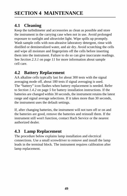
5. Gently bend the wires of the new lamp assembly into an “L” shapeso they fit easily into the housing. Insert the leads into the terminalscrews and tighten with clockwise turns. Gently tug on the wires tomake sure they are connected to the terminal block.
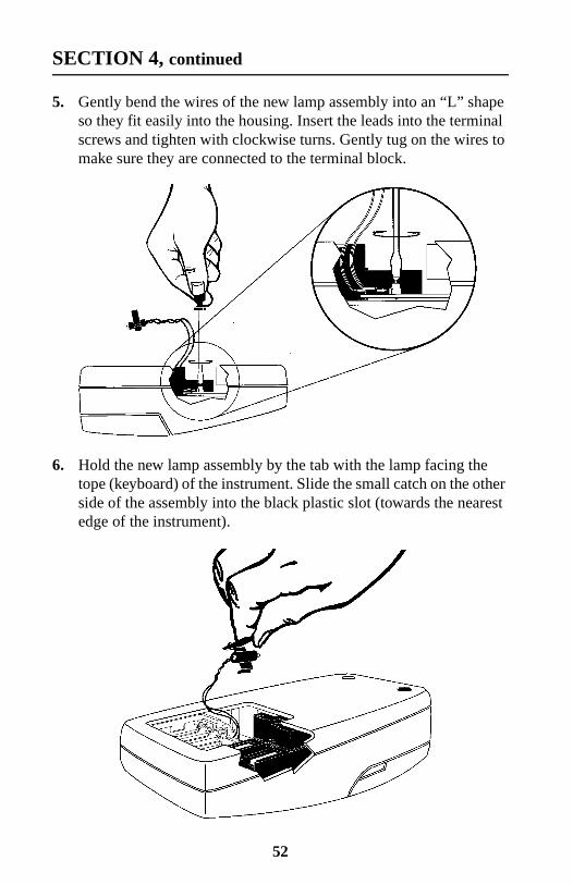
6. Hold the new lamp assembly by the tab with the lamp facing thetope (keyboard) of the instrument. Slide the small catch on the otherside of the assembly into the black plastic slot (towards the nearestedge of the instrument).
52

SECTION 4, continued
7. Snap the U-shaped bottom of the tab into the slot on the left side ofthe black plastic that holds the lamp assembly.
8. With your thumb, firmly slide the assembly forward until it stops.Again, push firmly against the tab to make sure the lamp is seatedcorrectly.
53

SECTION 4, continued
9. Replace the battery(s) and battery cover.
10. Insert the 800 NTU formazin standard into the sample cell. Pressand hold READ. Then press I/O. Release the READ key after thesoftware version number disappears from the display (for modelswith serial numbers less than 920300000800, 2100 disappears).
54
SECTION 4, continued
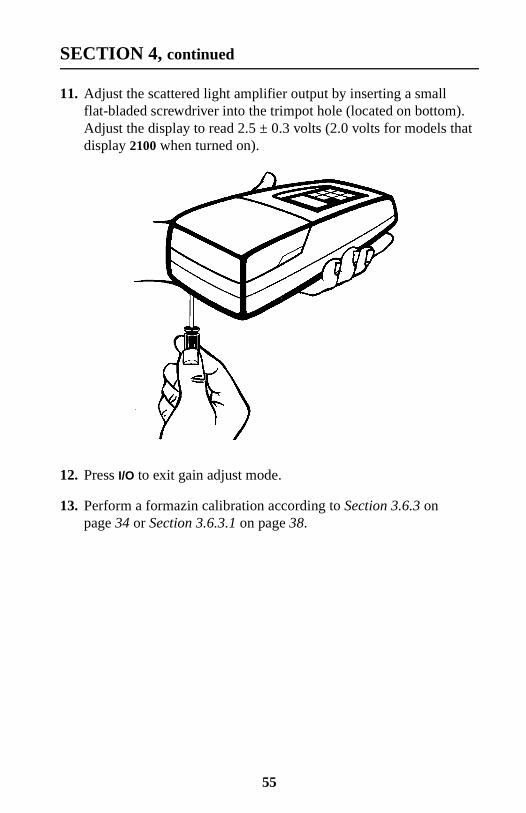
11. Adjust the scattered light amplifier output by inserting a smallflat-bladed screwdriver into the trimpot hole (located on bottom).Adjust the display to read 2.5 ± 0.3 volts (2.0 volts for models thatdisplay 2100 when turned on).
12. Press I/O to exit gain adjust mode.
13. Perform a formazin calibration according to Section 3.6.3 onpage 34 or Section 3.6.3.1 on page 38.
55

56
SECTION 5 TROUBLESHOOTING
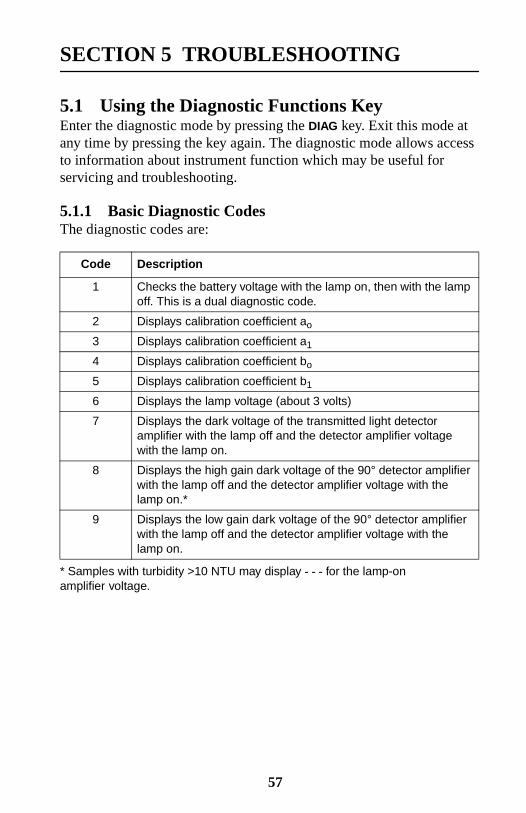
5.1 Using the Diagnostic Functions KeyEnter the diagnostic mode by pressing the DIAG key. Exit this mode atany time by pressing the key again. The diagnostic mode allows accessto information about instrument function which may be useful forservicing and troubleshooting.
5.1.1 Basic Diagnostic CodesThe diagnostic codes are:
Code Description
1 Checks the battery voltage with the lamp on, then with the lampoff. This is a dual diagnostic code.
2 Displays calibration coefficient ao
3 Displays calibration coefficient a1
4 Displays calibration coefficient bo
5 Displays calibration coefficient b1
6 Displays the lamp voltage (about 3 volts)
7 Displays the dark voltage of the transmitted light detectoramplifier with the lamp off and the detector amplifier voltagewith the lamp on.
8 Displays the high gain dark voltage of the 90° detector amplifierwith the lamp off and the detector amplifier voltage with thelamp on.*
* Samples with turbidity >10 NTU may display - - - for the lamp-onamplifier voltage.
9 Displays the low gain dark voltage of the 90° detector amplifierwith the lamp off and the detector amplifier voltage with thelamp on.
57
SECTION 5, continued
5.2 The Diagnostic Procedure
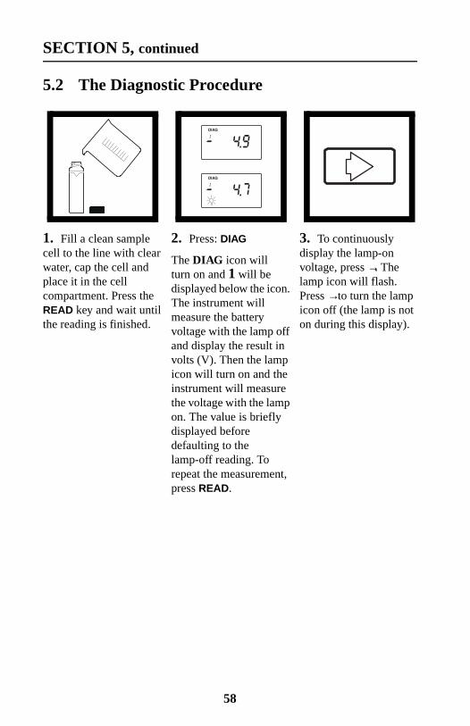
1. Fill a clean samplecell to the line with clearwater, cap the cell andplace it in the cellcompartment. Press theREAD key and wait untilthe reading is finished.
2. Press: DIAG
The DIAG icon willturn on and 1 will bedisplayed below the icon.The instrument willmeasure the batteryvoltage with the lamp offand display the result involts (V). Then the lampicon will turn on and theinstrument will measurethe voltage with the lampon. The value is brieflydisplayed beforedefaulting to thelamp-off reading. Torepeat the measurement,press READ.
3. To continuouslydisplay the lamp-onvoltage, press →. Thelamp icon will flash.Press →to turn the lampicon off (the lamp is noton during this display).
58

SECTION 5, continued
4. Press the ↑ key toscroll through the otherdiagnostics. Each pressof the key increments thedigit in the smallnumerical display belowthe DIAG icon and theresult of the diagnosticmeasurement is thendisplayed. Each press ofthe READ key updatesthe value. Formeasurements made withthe lamp off and againwith the lamp on, themeasurement with thelamp off is displayedwhen the diagnostic isentered. To see thesecond measurementwith the lamp on, pressthe →key (only workswith diagnostic codes1, 7, 8, & 9). The lampicon will flash and thelamp-on measurementwill be displayed in volts.Press →to turn the lampicon off.
Note: DIAG 8 will display---- for the lamp-on voltageif a of >10 NTU is placed inthe cell compartment.
59
SECTION 5, continued
5.3 Other Instrument Diagnostics
5.3.1 Display TestPressing and holding the I/O key turns on all the display icons andelements so you can determine if all the elements and icons arefunctioning. The display test sequence will cycle as long as the keyis held down.
5.4 Error MessagesError messages indicate sample interferences and/orinstrument malfunction.
5.4.1 Flashing Numeric DisplayIf the highest value in the range selected is flashing in the display, thesample is too turbid (or overrange) for the selected range. In automaticor manual range, 1000 flashes if the sample is over the instrument'srange. In manual range mode, select the next higher range mode if 9.99or 99.9 flashes. See Section 2.3.6 on page 21 for measuring overrangesamples. The display will stop flashing if a sample within range isinserted and read.
5.4.2 E MessagesAn error message indicates either an instrument failure or an operationcannot be performed. An error message can be cleared by pressingDIAG (display will return to previous measurement or calibration value).The meter continues to operate as best it can. If the message occursduring a calibration, calibration can continue. If the error messageoccurs when a calibration is being calculated, the instrument willdiscard the new calibration and retain the old calibration. Errormessages and corrective actions are listed below.
5.4.3 CAL?A flashing CAL? appears when the instrument is using the defaultcalibration programmed at the factory. It will appear if the analyst haserased the user-entered calibration using the procedure to restore thedefault calibration or after and E 4 error is cleared by pressing DIAG.Recalibrate as soon as possible when CAL? appears. CAL? (notflashing) appears when a calibration has questionable validity.
60
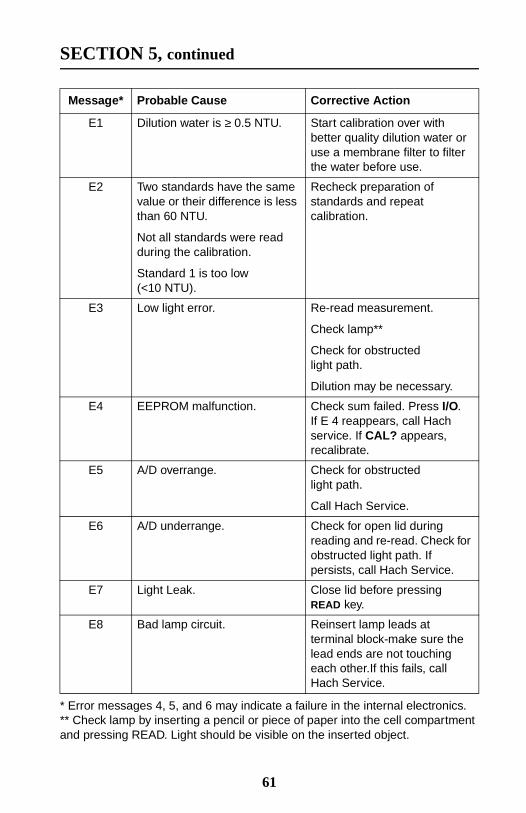
SECTION 5, continued
Message* Probable Cause Corrective Action
E1 Dilution water is ≥ 0.5 NTU. Start calibration over withbetter quality dilution water oruse a membrane filter to filterthe water before use.
E2 Two standards have the samevalue or their difference is lessthan 60 NTU.
Not all standards were readduring the calibration.
Standard 1 is too low(<10 NTU).
Recheck preparation ofstandards and repeatcalibration.
E3 Low light error. Re-read measurement.
Check lamp**
Check for obstructedlight path.
Dilution may be necessary.
E4 EEPROM malfunction. Check sum failed. Press I/O.If E 4 reappears, call Hachservice. If CAL? appears,recalibrate.
E5 A/D overrange. Check for obstructedlight path.
Call Hach Service.
E6 A/D underrange. Check for open lid duringreading and re-read. Check forobstructed light path. Ifpersists, call Hach Service.
E7 Light Leak. Close lid before pressingREAD key.
E8 Bad lamp circuit. Reinsert lamp leads atterminal block-make sure thelead ends are not touchingeach other.If this fails, callHach Service.
* Error messages 4, 5, and 6 may indicate a failure in the internal electronics.** Check lamp by inserting a pencil or piece of paper into the cell compartmentand pressing READ. Light should be visible on the inserted object.
61

62

GENERAL INFORMATION
At Hach Company, customer service is an importantpart of every product we make.
With that in mind, we have compiled thefollowing information for your convenience.
63

64
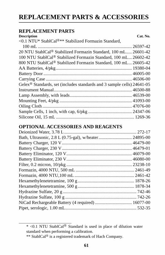
REPLACEMENT PARTS & ACCESSORIES
REPLACEMENT PARTSDescription Cat. No.<0.1 NTU* StablCal®** Stabilized Formazin Standard,
100 mL .................................................................................. 26597-4220 NTU StablCal® Stabilized Formazin Standard, 100 mL..... 26601-42100 NTU StablCal® Stabilized Formazin Standard, 100 mL... 26602-42800 NTU StablCal® Stabilized Formazin Standard, 100 mL... 26605-42AA Batteries, 4/pkg .................................................................. 19380-04Battery Door ............................................................................. 46005-00Carrying Case ........................................................................... 46506-00Gelex® Standards, set (includes standards and 3 sample cells) 24641-05Instrument Manual.................................................................... 46500-88Lamp Assembly, with leads...................................................... 46539-00Mounting Feet, 4/pkg ............................................................... 41093-00Oiling Cloth .............................................................................. 47076-00Sample Cells, 1 inch, with cap, 6/pkg ...................................... 24347-06Silicone Oil, 15 mL .................................................................... 1269-36
OPTIONAL ACCESSORIES AND REAGENTSDeionized Water, 3.78 L............................................................... 272-17Bath, Ultrasonic, 2.8 L (0.75-gal), w/heater............................. 24895-00Battery Charger, 120 V............................................................. 46479-00Battery Charger, 230 V............................................................. 46479-01Battery Eliminator, 120 V......................................................... 46079-00Battery Eliminator, 230 V......................................................... 46080-00Filter, 0.2 micron, 10/pkg ......................................................... 23238-10Formazin, 4000 NTU, 500 mL ................................................... 2461-49Formazin, 4000 NTU,100 mL .................................................... 2461-42Hexamethylenetetramine, 100 g ................................................. 1878-26Hexamethylenetetramine, 500 g ................................................. 1878-34Hydrazine Sulfate, 20 g ................................................................ 742-46Hydrazine Sulfate, 100 g .............................................................. 742-26NiCad Rechargeable Battery (4 required) ................................ 16077-00Pipet, serologic, 1.00 mL.............................................................. 532-35
* <0.1 NTU StablCal® Standard is used in place of dilution waterstandard when performing a calibration.** StablCal® is a registered trademark of Hach Company.
61
REPLACEMENT PARTS & ACCESSORIES, continued
OPTIONAL ACCESSORIES AND REAGENTS, continuedDescription Cat. No.Pipet, TenSette®*, 1-10 mL...................................................... 19700-10Pipet Tips, for 1-10 mL TenSette Pipet, 50/pkg ....................... 21997-96Pipet Tips, for 1-10 mL TenSette Pipet, 1000/pkg ................... 21997-28Pipet, Volumetric, Class A, 1.00 mL ........................................ 14515-35Pipet, Volumetric, Class A, 5.00 mL ........................................ 14515-37Pump, Vacuum, Hand-Operated ............................................... 14283-00Pump, Vacuum, 115 V, 60 Hz................................................... 14697-00Pump, Vacuum, 230 V, 50 Hz................................................... 14697-02Sample Degassing Kit............................................................... 43975-00Sample Filtration and Degassing Kit ........................................ 43975-10StablCal® Low Level Turbidity Standards for Instrument Verification**
0.1 NTU, 100 mL .................................................................. 27233-420.3 NTU, 100 mL .................................................................. 26979-430.5 NTU, 100 mL .................................................................. 26980-42
StablCal® Calibration Set for 2100P Turbidimeter<0.1, 20, 100, 800 NTU, 500 mL each.................................. 26594-00<0.1, 20, 100, 800 NTU, 100 mL each.................................. 26594-10<0.1, 20, 100, 800 NTU, sealed vials .................................... 26594-05
Triton-X Solution, 118 mL (4 oz)............................................. 14096-32Volumetric Flask, 100 mL ........................................................ 14574-42Volumetric Flask, 200 mL ........................................................ 14574-45
* TenSette™ is a Hach Company trademark.** Do not use these standards for instrument calibration.
62

HOW TO ORDER
By Telephone: By Mail:6:30 a.m. to 5:00 p.m. MST Hach CompanyMonday through Friday P.O. Box 389(800) 227-HACH Loveland, Colorado 80539-0389(800-227-4224) U.S.A.By FAX: Ordering information by E-mail:(970) 669-2932 [email protected]
Information Required
Technical and Customer Service (U.S.A. only)Hach Technical and Customer Service Department personnel are eagerto answer questions about our products and their use. Specialists inanalytical methods, they are happy to put their talents to work for you.Call 1-800-227-4224 or E-mail [email protected].
International CustomersHach maintains a worldwide network of dealers and distributors.To locate the representative nearest you, send E-mail tointl@hach. com or contact:
In Europe, the Middle East, or Mediterranean Africa:Hach Europe, S.A./N.V.; Namur, BelgiumTelephone: (32)(8l) 44.71.71; FAX: (32)(81) 44.13.00
In Canada:Hach Sales & Service Canada Ltd.; Manitoba, CanadaTelephone: (204) 632-5598; FAX: (204) 694-5134
In Latin America, the Caribbean, the Far East,the Indian Subcontinent, Africa, or the Pacific Basin:Hach Company World Headquarters; Loveland, Colorado, U.S.A.Telephone: (970) 669-3050; FAX: (970) 669-2932
• Hach account number (if available) • Billing address
• Your name and phone number • Shipping address
• Purchase order number • Catalog number
• Brief description or model number • Quantity
67

REPAIR SERVICE
Authorization must be obtained from Hach Company before sendingany items for repair. Please contact the Hach Service Center servingyour location.
In the United States:Hach Company100 Dayton Ave.Ames, Iowa 50010(800) 227-4224 (U.S.A. only)Telephone: (515) 232-2533FAX: (515) 232-1276
In Canada:Hach Sales & Service Canada Ltd.1313 Border Street, Unit 34Winnipeg, ManitobaR3H 0X4(800) 665-7635 (Canada only)Telephone: (204) 632-5598FAX: (204) 694-5134
In Latin America, the Caribbean, the Far East, theIndian Subcontinent, Africa (except Mediterranean Africa) orBasin:Hach Company World Headquarters,P.O. Box 389Loveland, Colorado 80539-0389 U.S.A.Telephone: (970) 669-3050FAX: (970) 669-2932
In Europe, the Middle East, or in Mediterranean Africa:Hach Europe, S.A./N.V.Chaussée de Namur, 1B-5150 Floriffoux (Namur), BelgiumTelephone: (32)(8l) 44.71.71FAX: (32)(81) 44.13.00
68
WARRANTY
Hach warrants most products against defective materials orworkmanship for at least one year from the date of shipment;longer warranties may apply to some items.
HACH WARRANTS TO THE ORIGINAL BUYER THAT HACHPRODUCTS WILL CONFORM TO ANY EXPRESS WRITTENWARRANTY GIVEN BY HACH TO THE BUYER. EXCEPT ASEXPRESSLY SET FORTH IN THE PRECEDING SENTENCE,HACH MAKES NO WARRANTY OF ANY KIND WHATSOEVERWITH RESPECT TO ANY PRODUCTS. HACH EXPRESSLYDISCLAIMS ANY WARRANTIES IMPLIED BY LAW, INCLUDINGBUT NOT LIMITED TO ANY WARRANTY OF MERCHANTABILITYOR FITNESS FOR A PARTICULAR PURPOSE.
LIMITATION OF REMEDIES: Hach shall, at its option, replaceor repair nonconforming products or refund all amounts paid bythe buyer. THIS IS THE EXCLUSIVE REMEDY FOR ANY BREACHOF WARRANTY.
LIMITATION OF DAMAGES: IN NO EVENT SHALL HACHBE LIABLE FOR ANY INCIDENTAL OR CONSEQUENTIALDAMAGES OF ANY KIND FOR BREACH OF ANY WARRANTY,NEGLIGENCE, ON THE BASIS OF STRICT LIABILITY,OR OTHERWISE.
This warranty applies only to Hach products purchased and deliveredin the United States.
Catalog descriptions, pictures and specifications, although accurate tothe best of our knowledge, are not a guarantee or warranty.
For a complete description of Hach Company’s warranty policy, requesta copy of our Terms and Conditions of Sale for U.S. Sales from ourCustomer Service Department.
69


IMPORTANT NOTICE
Immediate Attention Required
REGISTER YOUR INSTRUMENT NOW
The 2100P Portable Turbidimeter instrument manual is designed to beupdated as new information becomes available. Update information willbe provided periodically through our company publications.
Update information will be mailed directly to end users who complete andreturn the attached registration form. Information about new accessoriesalso will be provided directly to you. To ensure you are kept up to date,please complete and mail the registration today.
If you are located outside the U.S.A., please complete the form and mail itin an envelope addressed to: Hach Company, P.O. Box 389, Loveland,Colorado, 80539-0389, U.S.A.
Thank you for your assistance.
2100P Portable Turbidimeter Registration Card
Name ________________________ Title ________________________
Dept./Division ______________ Company _______________________
Street Address___________________________P.O. Box ____________
City______________ State/Province________ Zip/Postal Code _______
Phone Number ____________________ FAX _____________________
Meter Catalog Number ________________
Purchase Date ___________________ In Service Date ______________
Serial Number __________________ Customer Number ____________
Purchased From (if not purchased directly from Hach)
__________________________________________________________


46500-44
Quick Reference CardPORTABLE TURBIDIMETER
Turbidity Measurement Procedure
Calibration (factory standards)1. Prepare stock formazin solution 48 hours before calibration.
See Calibration in the instrument manual.
2. Prepare 20, 100, and 800 NTU standards. See PreparingFormazin Dilutions (Factory recommended) in the instrumentmanual.
3. Perform calibration. See Calibrating the Turbidimeter in theinstrument manual.
1. Fill and cap sample cells.Wipe cells.
2. Turn instrument on. Selectmeasurement range and turn signalaveraging on or off.
3. Insert sample cell. Press: READ. 4. Record turbidity after lamp iconturns off.
Recordresults

Error Codes
Error IndicatorsFlashing maximum concentration: Concentration exceeds upperlimit of range selection. See Measuring Overrange Samples orFlashing Numeric Display in the instrument manual.
Flashing CAL?: Default calibration values in use. See Calibration inthe instrument manual to recalibrate.
Flashing lamp icon: Low light level. See Operational Controls andIndicators in the instrument manual.
Flashing battery icon: Low battery. See Battery Replacement in theinstrument manual.
Message*
* Error messages 4, 5, and 6 may indicate a failure in the internal electronics.
Probable Cause
E1 Dilution water is > 0.5 NTU. See Correcting for Turbidity ofDilution Water in the instrument manual.
E2 Two standards have values ≤60 NTU apart. See PreparingFormazin Dilutions (Factory recommended) or Preparing User-selected Formazin Dilutions in the instrument manual.
Not all standards were read during the calibration. SeeCalibrating the Turbidimeter or Preparing User-selectedFormazin Dilutions in the instrument manual.
Standard 1 is too low (<10 NTU). See Section 3.6.3 onpage 34 or Section 3.6.3.1 on page 38
E3 Low light error. See E Messages in the instrument manual.
E4 EEPROM malfunction. Call Hach Service.
E5 A/D overrange. Check for light path obstruction. Call HachService if error persists.
E6 A/D underrange. Be sure lid is closed and re-read. Call HachService if error persists.
E7 Light Leak. Close lid before pressing READ key.
E8 Bad lamp circuit. Ensure lamp lead ends are not touching. CallHach Service if error persists.
© Hach Company, 1992-1998. All rights reserved. Printed in U.S.A. 6/98 5 ed
For Technical Assistance, Price and OrderingIn the U.S.A.—Call 800-227-4224Outside the U.S.A.—Contact the Hach office or distributor serving you.