instrumentation and control systems important to safety in ... · pdf fileiaea safety...
TRANSCRIPT

IAEASAFETY
STANDARDSSERIES
Instrumentation and Control SystemsImportant to Safety inNuclear Power Plants
SAFETY GUIDENo. NS-G-1.3
INTERNATIONAL ATOMIC ENERGY AGENCYVIENNA
This publication has been superseded by SSG-39

IAEA SAFETY RELATED PUBLICATIONS
IAEA SAFETY STANDARDS
Under the terms of Article III of its Statute, the IAEA is authorized to establish standardsof safety for protection against ionizing radiation and to provide for the application of thesestandards to peaceful nuclear activities.
The regulatory related publications by means of which the IAEA establishes safetystandards and measures are issued in the IAEA Safety Standards Series. This series coversnuclear safety, radiation safety, transport safety and waste safety, and also general safety (thatis, of relevance in two or more of the four areas), and the categories within it are SafetyFundamentals, Safety Requirements and Safety Guides.
Safety Fundamentals (blue lettering) present basic objectives, concepts and principles ofsafety and protection in the development and application of nuclear energy for peacefulpurposes.
Safety Requirements (red lettering) establish the requirements that must be met to ensuresafety. These requirements, which are expressed as ‘shall’ statements, are governed bythe objectives and principles presented in the Safety Fundamentals.
Safety Guides (green lettering) recommend actions, conditions or procedures for meetingsafety requirements. Recommendations in Safety Guides are expressed as ‘should’ state-ments, with the implication that it is necessary to take the measures recommended orequivalent alternative measures to comply with the requirements.
The IAEA’s safety standards are not legally binding on Member States but may beadopted by them, at their own discretion, for use in national regulations in respect of their ownactivities. The standards are binding on the IAEA in relation to its own operations and on Statesin relation to operations assisted by the IAEA.
Information on the IAEA’s safety standards programme (including editions in languagesother than English) is available at the IAEA Internet site
www.iaea.org/ns/coordinet or on request to the Safety Co-ordination Section, IAEA, P.O. Box 100, A-1400 Vienna, Austria.
OTHER SAFETY RELATED PUBLICATIONS
Under the terms of Articles III and VIII.C of its Statute, the IAEA makes available andfosters the exchange of information relating to peaceful nuclear activities and serves as an inter-mediary among its Member States for this purpose.
Reports on safety and protection in nuclear activities are issued in other series, inparticular the IAEA Safety Reports Series, as informational publications. Safety Reports maydescribe good practices and give practical examples and detailed methods that can be used tomeet safety requirements. They do not establish requirements or make recommendations.
Other IAEA series that include safety related sales publications are the TechnicalReports Series, the Radiological Assessment Reports Series and the INSAG Series. TheIAEA also issues reports on radiological accidents and other special sales publications.Unpriced safety related publications are issued in the TECDOC Series, the Provisional SafetyStandards Series, the Training Course Series, the IAEA Services Series and the ComputerManual Series, and as Practical Radiation Safety Manuals and Practical RadiationTechnical Manuals.
This publication has been superseded by SSG-39

INSTRUMENTATION AND CONTROL SYSTEMSIMPORTANT TO SAFETY INNUCLEAR POWER PLANTS
This publication has been superseded by SSG-39

The Agency’s Statute was approved on 23 October 1956 by the Conference on the Statute of theIAEA held at United Nations Headquarters, New York; it entered into force on 29 July 1957. TheHeadquarters of the Agency are situated in Vienna. Its principal objective is “to accelerate and enlarge thecontribution of atomic energy to peace, health and prosperity throughout the world’’.
© IAEA, 2002
Permission to reproduce or translate the information contained in this publication may beobtained by writing to the International Atomic Energy Agency, Wagramer Strasse 5, P.O. Box 100,A-1400 Vienna, Austria.
Printed by the IAEA in AustriaMarch 2002
STI/PUB/1116
The following States are Members of the International Atomic Energy Agency:
AFGHANISTANALBANIAALGERIAANGOLAARGENTINAARMENIAAUSTRALIAAUSTRIAAZERBAIJANBANGLADESHBELARUSBELGIUMBENINBOLIVIABOSNIA AND HERZEGOVINABRAZILBULGARIABURKINA FASOCAMBODIACAMEROONCANADACENTRAL AFRICAN
REPUBLICCHILECHINACOLOMBIACOSTA RICACÔTE D’IVOIRECROATIACUBACYPRUSCZECH REPUBLICDEMOCRATIC REPUBLIC
OF THE CONGODENMARKDOMINICAN REPUBLICECUADOREGYPTEL SALVADORESTONIAETHIOPIAFINLANDFRANCEGABONGEORGIAGERMANYGHANA
GREECEGUATEMALAHAITIHOLY SEEHUNGARYICELANDINDIAINDONESIAIRAN, ISLAMIC REPUBLIC OF IRAQIRELANDISRAELITALYJAMAICAJAPANJORDANKAZAKHSTANKENYAKOREA, REPUBLIC OFKUWAITLATVIALEBANONLIBERIALIBYAN ARAB JAMAHIRIYALIECHTENSTEINLITHUANIALUXEMBOURGMADAGASCARMALAYSIAMALIMALTAMARSHALL ISLANDSMAURITIUSMEXICOMONACOMONGOLIAMOROCCOMYANMARNAMIBIANETHERLANDSNEW ZEALANDNICARAGUANIGERNIGERIANORWAYPAKISTANPANAMA
PARAGUAYPERUPHILIPPINESPOLANDPORTUGALQATARREPUBLIC OF MOLDOVAROMANIARUSSIAN FEDERATIONSAUDI ARABIASENEGALSIERRA LEONESINGAPORESLOVAKIASLOVENIASOUTH AFRICASPAINSRI LANKASUDANSWEDENSWITZERLANDSYRIAN ARAB REPUBLICTAJIKISTANTHAILANDTHE FORMER YUGOSLAV
REPUBLIC OF MACEDONIATUNISIATURKEYUGANDAUKRAINEUNITED ARAB EMIRATESUNITED KINGDOM OF
GREAT BRITAIN AND NORTHERN IRELAND
UNITED REPUBLICOF TANZANIA
UNITED STATES OF AMERICAURUGUAYUZBEKISTANVENEZUELAVIET NAMYEMENYUGOSLAVIA,
FEDERAL REPUBLIC OFZAMBIAZIMBABWE
This publication has been superseded by SSG-39

INSTRUMENTATION ANDCONTROL SYSTEMS
IMPORTANT TO SAFETY IN NUCLEAR POWER PLANTS
SAFETY GUIDE
SAFETY STANDARDS SERIES No. NS-G-1.3
INTERNATIONAL ATOMIC ENERGY AGENCYVIENNA, 2002
This publication has been superseded by SSG-39

VIC Library Cataloguing in Publication Data
Instrumentation and control systems important to safety in nuclear power plants : safety guide. — Vienna : International Atomic Energy Agency,2002.
p. ; 24 cm. — (Safety standards series, ISSN 1020–525X ; no. NS-G-1.3)STI/PUB/1116ISBN 92–0–110802–8Includes bibliographical references.
1. Nuclear power plants — Control rooms — Safety measures. 2. Nuclearpower plants — Instruments. I. International Atomic Energy Agency.II. Series.
VICL 01–00272
This publication has been superseded by SSG-39

FOREWORD
by Mohamed ElBaradeiDirector General
One of the statutory functions of the IAEA is to establish or adopt standards ofsafety for the protection of health, life and property in the development and applicationof nuclear energy for peaceful purposes, and to provide for the application of thesestandards to its own operations as well as to assisted operations and, at the request ofthe parties, to operations under any bilateral or multilateral arrangement, or, at therequest of a State, to any of that State’s activities in the field of nuclear energy.
The following bodies oversee the development of safety standards: theCommission for Safety Standards (CSS); the Nuclear Safety Standards Committee(NUSSC); the Radiation Safety Standards Committee (RASSC); the Transport SafetyStandards Committee (TRANSSC); and the Waste Safety Standards Committee(WASSC). Member States are widely represented on these committees.
In order to ensure the broadest international consensus, safety standards arealso submitted to all Member States for comment before approval by the IAEA Boardof Governors (for Safety Fundamentals and Safety Requirements) or, on behalf of theDirector General, by the Publications Committee (for Safety Guides).
The IAEA’s safety standards are not legally binding on Member States but maybe adopted by them, at their own discretion, for use in national regulations in respectof their own activities. The standards are binding on the IAEA in relation to its ownoperations and on States in relation to operations assisted by the IAEA. Any Statewishing to enter into an agreement with the IAEA for its assistance in connectionwith the siting, design, construction, commissioning, operation or decommissioningof a nuclear facility or any other activities will be required to follow those parts of thesafety standards that pertain to the activities to be covered by the agreement.However, it should be recalled that the final decisions and legal responsibilities in anylicensing procedures rest with the States.
Although the safety standards establish an essential basis for safety, theincorporation of more detailed requirements, in accordance with national practice,may also be necessary. Moreover, there will generally be special aspects that need tobe assessed on a case by case basis.
The physical protection of fissile and radioactive materials and of nuclearpower plants as a whole is mentioned where appropriate but is not treated in detail;obligations of States in this respect should be addressed on the basis of the relevantinstruments and publications developed under the auspices of the IAEA. Non-radiological aspects of industrial safety and environmental protection are also notexplicitly considered; it is recognized that States should fulfil their internationalundertakings and obligations in relation to these.
This publication has been superseded by SSG-39

The requirements and recommendations set forth in the IAEA safety standardsmight not be fully satisfied by some facilities built to earlier standards. Decisions onthe way in which the safety standards are applied to such facilities will be taken byindividual States.
The attention of States is drawn to the fact that the safety standards of theIAEA, while not legally binding, are developed with the aim of ensuring that thepeaceful uses of nuclear energy and of radioactive materials are undertaken in amanner that enables States to meet their obligations under generally acceptedprinciples of international law and rules such as those relating to environmentalprotection. According to one such general principle, the territory of a State must notbe used in such a way as to cause damage in another State. States thus have anobligation of diligence and standard of care.
Civil nuclear activities conducted within the jurisdiction of States are, as anyother activities, subject to obligations to which States may subscribe underinternational conventions, in addition to generally accepted principles of internationallaw. States are expected to adopt within their national legal systems such legislation(including regulations) and other standards and measures as may be necessary to fulfilall of their international obligations effectively.
EDITORIAL NOTE
An appendix, when included, is considered to form an integral part of the standard andto have the same status as the main text. Annexes, footnotes and bibliographies, if included, areused to provide additional information or practical examples that might be helpful to the user.
The safety standards use the form ‘shall’ in making statements about requirements,responsibilities and obligations. Use of the form ‘should’ denotes recommendations of adesired option.
The English version of the text is the authoritative version.
This publication has been superseded by SSG-39

CONTENTS
1. INTRODUCTION . . . . . . . . . . . . . . . . . . . . . . . . . . . . . . . . . . . . . . . . . . 1
Background (1.1–1.3) . . . . . . . . . . . . . . . . . . . . . . . . . . . . . . . . . . . . . . . . 1Objective (1.4–1.6) . . . . . . . . . . . . . . . . . . . . . . . . . . . . . . . . . . . . . . . . . . 1Scope (1.7–1.9) . . . . . . . . . . . . . . . . . . . . . . . . . . . . . . . . . . . . . . . . . . . . 2Structure (1.10–1.12) . . . . . . . . . . . . . . . . . . . . . . . . . . . . . . . . . . . . . . . . 2
2. INSTRUMENTATION AND CONTROL SYSTEMS IMPORTANTTO SAFETY (2.1) . . . . . . . . . . . . . . . . . . . . . . . . . . . . . . . . . . . . . . . . . . 3
Identification of I&C systems (2.2–2.35) . . . . . . . . . . . . . . . . . . . . . . . . . 3Classification of I&C systems (2.36–2.45) . . . . . . . . . . . . . . . . . . . . . . . . 11
3. THE DESIGN BASIS (3.1–3.3) . . . . . . . . . . . . . . . . . . . . . . . . . . . . . . . . 14
Categories of plant states (3.4–3.18) . . . . . . . . . . . . . . . . . . . . . . . . . . . . . 14
4. GENERAL DESIGN GUIDELINES (4.1–4.2) . . . . . . . . . . . . . . . . . . . . . 18
Performance requirements (4.3–4.7) . . . . . . . . . . . . . . . . . . . . . . . . . . . . . 18Design for reliability (4.8–4.35) . . . . . . . . . . . . . . . . . . . . . . . . . . . . . . . . 20Independence (4.36–4.48) . . . . . . . . . . . . . . . . . . . . . . . . . . . . . . . . . . . . 26Failure modes (4.49–4.50) . . . . . . . . . . . . . . . . . . . . . . . . . . . . . . . . . . . . 28Control of access to equipment (4.51–4.53) . . . . . . . . . . . . . . . . . . . . . . . 29Set points (4.54–4.60) . . . . . . . . . . . . . . . . . . . . . . . . . . . . . . . . . . . . . . . 29Human–machine interface (4.61) . . . . . . . . . . . . . . . . . . . . . . . . . . . . . . . 31Equipment qualification (4.62–4.73) . . . . . . . . . . . . . . . . . . . . . . . . . . . . . 31Quality (4.74–4.76) . . . . . . . . . . . . . . . . . . . . . . . . . . . . . . . . . . . . . . . . . 34Design for electromagnetic compatibility (4.77–4.78) . . . . . . . . . . . . . . . . 34Testing and testability (4.79–4.96) . . . . . . . . . . . . . . . . . . . . . . . . . . . . . . 34Maintainability (4.97–4.103) . . . . . . . . . . . . . . . . . . . . . . . . . . . . . . . . . . 38Documentation (4.104–4.106) . . . . . . . . . . . . . . . . . . . . . . . . . . . . . . . . . 39Identification of items important to safety (4.107–4.108) . . . . . . . . . . . . . 40
5. SYSTEM SPECIFIC DESIGN GUIDELINES (5.1) . . . . . . . . . . . . . . . . . 41
Safety systems (5.2) . . . . . . . . . . . . . . . . . . . . . . . . . . . . . . . . . . . . . . . . . 41Protection systems (5.3–5.38) . . . . . . . . . . . . . . . . . . . . . . . . . . . . . . . . . . 41
This publication has been superseded by SSG-39

Power supplies (5.39–5.42) . . . . . . . . . . . . . . . . . . . . . . . . . . . . . . . . . . . 50Digital computer systems (5.43–5.59) . . . . . . . . . . . . . . . . . . . . . . . . . . . . 50
6. HUMAN–MACHINE INTERFACE (6.1–6.10) . . . . . . . . . . . . . . . . . . . . 53
Main control room (6.11–6.14) . . . . . . . . . . . . . . . . . . . . . . . . . . . . . . . . . 54Supplementary control rooms (6.15–6.30) . . . . . . . . . . . . . . . . . . . . . . . . 56Emergency response facilities (6.31–6.34) . . . . . . . . . . . . . . . . . . . . . . . . 58Control facilities (6.35–6.39) . . . . . . . . . . . . . . . . . . . . . . . . . . . . . . . . . . 59Displays (6.40–6.47) . . . . . . . . . . . . . . . . . . . . . . . . . . . . . . . . . . . . . . . . 60Monitoring of accident conditions (6.48–6.56) . . . . . . . . . . . . . . . . . . . . . 61Systems for alarm annunciation (6.57–6.62) . . . . . . . . . . . . . . . . . . . . . . . 63Recording system for historical data (6.63–6.65) . . . . . . . . . . . . . . . . . . . 64
7. DESIGN PROCESS FOR I&CSYSTEMS IMPORTANT TO SAFETY (7.1) . . . . . . . . . . . . . . . . . . . . . . 64
Quality assurance (7.2–7.3) . . . . . . . . . . . . . . . . . . . . . . . . . . . . . . . . . . . 65Project planning (7.4) . . . . . . . . . . . . . . . . . . . . . . . . . . . . . . . . . . . . . . . . 65Change control and configuration management (7.5) . . . . . . . . . . . . . . . . 65Integration of human factors (7.6–7.10) . . . . . . . . . . . . . . . . . . . . . . . . . . 66Description of the design process (7.11–7.18) . . . . . . . . . . . . . . . . . . . . . 67Upgrades and backfits (7.19–7.24) . . . . . . . . . . . . . . . . . . . . . . . . . . . . . . 71Analyses required for safety systems (7.25–7.28) . . . . . . . . . . . . . . . . . . . 72Probabilistic safety assessment (7.29) . . . . . . . . . . . . . . . . . . . . . . . . . . . . 73Assumptions made in the analyses (7.30) . . . . . . . . . . . . . . . . . . . . . . . . . 73Documentation for the I&C system (7.31–7.72) . . . . . . . . . . . . . . . . . . . 73
REFERENCES . . . . . . . . . . . . . . . . . . . . . . . . . . . . . . . . . . . . . . . . . . . . . . . . . 81GLOSSARY . . . . . . . . . . . . . . . . . . . . . . . . . . . . . . . . . . . . . . . . . . . . . . . . . . . 83CONTRIBUTORS TO DRAFTING AND REVIEW . . . . . . . . . . . . . . . . . . . . . 89BODIES FOR THE ENDORSEMENT OF SAFETY STANDARDS . . . . . . . . . 91
This publication has been superseded by SSG-39

1
1. INTRODUCTION
BACKGROUND
1.1. This Safety Guide was prepared under the IAEA programme for establishingsafety standards for nuclear power plants. It supplements Safety Standards Series No.NS-R-1: Safety of Nuclear Power Plants: Design [1] (the Requirements for Design),which establishes the design requirements for ensuring the safety of nuclear powerplants. This Safety Guide describes how the requirements should be met for instru-mentation and control (I&C) systems important to safety.
1.2. This publication is a revision and combination of two previous Safety Guides:Safety Series Nos 50-SG-D3 and 50-SG-D8, which are superseded by this new SafetyGuide.
1.3. The revision takes account of developments in I&C systems important to safetysince the earlier Safety Guides were published in 1980 and 1984, respectively. Themain changes result from the following:
— In this Safety Guide, developments in the use of computer based I&C systemsimportant to safety are considered.
— Attention is given in this revision of Safety Series Nos 50-SG-D3 and 50-SG-D8to addressing all I&C systems important to safety. Guidance is organized andpresented in relation to the requirements and criteria set out in Ref. [1].
— This Safety Guide is intended to be read in conjunction with and relation to theRequirements for Design [1] and the Safety Guides in related areas, on software[2] and on quality assurance (Ref. [3], Safety Guides Q3 and Q10).
— Guidance is given on the classification of I&C systems important to safety,drawn from other international standards.
OBJECTIVE
1.4. The objective of this Safety Guide is to provide guidance on the design of I&Csystems important to safety in nuclear power plants, including all I&C components,from the sensors allocated to the mechanical systems to the actuated equipment,operator interfaces and auxiliary equipment.
1.5. This Safety Guide deals mainly with design requirements for those I&Csystems that are important to safety. It expands on paragraphs of Ref. [1] in the areaof I&C systems important to safety.
This publication has been superseded by SSG-39

1.6. This publication is intended for use primarily by designers of nuclear powerplants and also by owners and/or operators and regulators of nuclear power plants.
SCOPE
1.7. This Safety Guide provides general guidance on I&C systems important tosafety which is broadly applicable to many nuclear power plants. More detailedrequirements and limitations for safe operation specific to a particular plant typeshould be established as part of the design process. The present guidance is focusedon the design principles for systems important to safety that warrant particularattention, and should be applied to both the design of new I&C systems and the mod-ernization of existing systems. Guidance is provided on how design principles shouldbe applied, on the basis of a method of classifying systems by their importance tosafety.
1.8. In accordance with the definitions given in Ref. [1], I&C systems important tosafety are I&C systems that are part of a safety group and I&C systems whose mal-function or failure could lead to radiation exposure of site personnel or members ofthe public. Examples of such systems are:
— the reactor protection system,— reactor control systems,— systems to monitor and control normal reactor cooling,— systems to monitor and control emergency power supplies,— containment isolation systems.
1.9. The IAEA’s Technical Reports Series No. 387 [4] presents an overview of con-cepts and examples of systems discussed in this Safety Guide and may provide use-ful background material for some users.
STRUCTURE
1.10. This publication is organized in accordance with the requirements and criteriaof Ref. [1] and to provide guidelines on I&C systems important to safety.
1.11. Section 2 discusses the identification of I&C functions and systems within thescope of this Safety Guide, and their further classification into safety and safety relatedfunctions and systems. Section 3 describes the determination of the design basis forI&C systems important to safety. Section 4 provides design guidance for I&C systems
2
This publication has been superseded by SSG-39

important to safety. It includes guidance that applies to all I&C systems important tosafety as well as guidance that applies only to safety systems. Applicability of theguidance to these two classes is identified in the text and summarized in Table I.Section 5 provides additional guidance that is specific to certain I&C systems, namelyprotection systems, power supplies and digital computer systems. The guidance forthese systems comprises the general guidance provided in Section 4 and the specificguidance provided in Section 5. Section 6 expands on the guidance given in Section4 in the area of human–machine interfaces. Section 7 expands on the guidance givenin Section 4 in the area of design processes to ensure quality.
1.12. The discussion in Sections 4, 5, 6 and 7 is typically structured to describe therelevance of each topic to safety and to the Requirements for Design. Specific guidanceon each topic is provided.
2. INSTRUMENTATION AND CONTROL SYSTEMSIMPORTANT TO SAFETY
2.1. The Requirements for Design require that all I&C systems and components(including software for I&C) that are items important to safety shall be first identifiedand then classified on the basis of their function and significance for safety (Ref. [1],para. 5.1).
IDENTIFICATION OF I&C SYSTEMS
2.2. I&C systems important to safety are identified on the basis of the identificationof necessary I&C safety functions and the definition of systems that perform certaincombinations of these functions. The typical process for identifying systems importantto safety is discussed in this section.
Plant functions important to safety
2.3. There are a number of vital functions that must be performed to ensure the safeand efficient operation of a nuclear power plant and that may involve the use of I&Csystems. The following main safety functions that are required to be performed toensure safety are identified in Ref. [1], para. 4.6:
— control of reactivity,— removal of heat from the core, and
3
This publication has been superseded by SSG-39

— confinement of radioactive materials and control of operational discharges, aswell as limitation of accidental releases.
2.4. A systematic approach should be followed to identify the systems, structuresand components that are required to fulfil these safety functions following a postulatedinitiating event (PIE).
2.5. These main safety functions are extended and elaborated upon in the followingto describe more fully the functions that are required to be performed in order toensure safety. This extended set of functions includes functions necessary to avoid orprevent accident conditions as well as functions necessary to mitigate the conse-quences of accident conditions. They are accomplished, as appropriate, using thestructures, systems and components provided for normal operation, those provided toprevent anticipated operational occurrences from leading to accident conditions, orthose provided to mitigate the consequences of accident conditions.
Safety functions for the control of reactivity:
— provide for normal reactivity control within safe limits;— prevent unacceptable reactivity transients;— shut down the reactor as necessary to prevent anticipated operational occur-
rences from leading to design basis accident conditions;— shut down the reactor to mitigate the consequences of accident conditions; and— maintain the reactor in a safe shutdown condition after all shutdown actions.
Safety functions for the removal of heat from the core:
— remove heat from the core during power operations;— remove residual heat in appropriate operational states and design basis accident
conditions with the reactor coolant boundary intact;— maintain sufficient coolant inventory for core cooling in normal operational
states and following any PIEs;— remove heat from the core after a failure of the reactor coolant pressure bound-
ary in order to limit fuel damage; and— transfer heat to the ultimate heat sink from intermediate heat sinks used in
removing heat from the core.
Safety functions for the confinement of radioactive materials and control of opera-tional discharges as well as limitation of accidental releases:
— maintain the integrity of the cladding for the fuel in the reactor core;
4
This publication has been superseded by SSG-39

— maintain the integrity of the reactor coolant pressure boundary; and— limit the release of radioactive materials and minimize the exposure of the pub-
lic and personnel to radiation.
2.6. The aforementioned functions important to safety should be performed by engi-neered systems, of which some are I&C systems. For I&C systems, typical primaryfunctions that are important to safety include:
— protection functions,— control functions,— monitoring and display functions, and— testing functions.
2.7. In addition, there are service functions, also important to safety, which shouldbe carried out in support of the primary functions. Examples of such service functionsinclude the supply of electric, pneumatic or hydraulic power, data communications,and monitoring and testing functions which support the systems performing the pri-mary functions.
2.8. The primary I&C system functions that are important to safety can be charac-terized as follows:
Protection functions
2.9. Protection functions provide a line of defence against failures in other plantsystems. They are among the most critical of the safety functions and relate directlyto nuclear safety in terms of protecting personnel and the public in the event of aserious failure.
Control functions
2.10. Control functions provide assurance that the plant is controlled and kept withinits operating envelope under normal and abnormal conditions. Control functions canalso mitigate the effects of plant transients or PIEs, thereby contributing to nuclearsafety by minimizing the demand on protection functions.
Monitoring and display functions
2.11. Monitoring and display functions provide the interface between the plant andthe operations and maintenance personnel. These functions are important to safety as
5
This publication has been superseded by SSG-39
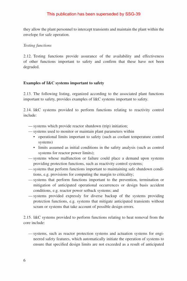
they allow the plant personnel to intercept transients and maintain the plant within theenvelope for safe operation.
Testing functions
2.12. Testing functions provide assurance of the availability and effectiveness of other functions important to safety and confirm that these have not been degraded.
Examples of I&C systems important to safety
2.13. The following listing, organized according to the associated plant functionsimportant to safety, provides examples of I&C systems important to safety.
2.14. I&C systems provided to perform functions relating to reactivity controlinclude:
— systems which provide reactor shutdown (trip) initiation;— systems used to monitor or maintain plant parameters within
• operational limits important to safety (such as coolant temperature controlsystems)
• limits assumed as initial conditions in the safety analysis (such as controlsystems for reactor power limits);
— systems whose malfunction or failure could place a demand upon systemsproviding protection functions, such as reactivity control systems;
— systems that perform functions important to maintaining safe shutdown condi-tions, e.g. provisions for computing the margin to criticality;
— systems that perform functions important to the prevention, termination ormitigation of anticipated operational occurrences or design basis accidentconditions, e.g. reactor power setback systems; and
— systems provided expressly for diverse backup of the systems providingprotection functions, e.g. systems that mitigate anticipated transients withoutscram or systems that take account of possible design errors.
2.15. I&C systems provided to perform functions relating to heat removal from thecore include:
— systems, such as reactor protection systems and actuation systems for engi-neered safety features, which automatically initiate the operation of systems toensure that specified design limits are not exceeded as a result of anticipated
6
This publication has been superseded by SSG-39

operational occurrences, to sense design basis accident conditions and mitigatetheir consequences, or to override unsafe actions of the control system; and
— systems which monitor or control plant environmental conditions that are nec-essary for the proper functioning of plant equipment important to safety andhabitability.
2.16. I&C systems provided to perform functions of confinement of radioactivematerials and control of operaional discharges, as well as limitation of accidentalreleases, include:
— systems whose malfunction or failure could cause a release of radioactive mate-rial to the environment and for which no safety system is provided, e.g. thosethat control waste management and spent fuel cooling;
— systems used to detect and measure leakage from the reactor coolant system;— systems which monitor or control natural or human made phenomena that could
adversely affect safety, e.g. seismic monitors; and— systems used for accident monitoring and assessment, e.g. those that monitor
and record, as necessary, containment pressure, containment activity, reactorcore cooling, radioactive releases to the environment and meteorological data.
2.17. I&C systems provided to support the achievement of other functions importantto safety include:
— systems that provide a support function to multiple I&C systems important tosafety, e.g. digital data communication systems that transmit signals betweensystems and between components of systems;
— systems used to monitor the status of safety systems, e.g. those that monitor forfailure of safety channels and defects in pipes, valves or pumps of safety sys-tems;
— systems that may be utilized in the operation of safety systems, e.g. for testingthe protection system; and
— other specific I&C applications important to safety, e.g. for communication, firedetection and suppression, and access control.
Types of I&C system important to safety
2.18. On the basis of the identification of safety functions that are required to becarried out, I&C systems are established to perform functions important to safety. Thefollowing types of systems are commonly used.
7
This publication has been superseded by SSG-39

Protection systems
2.19. Protection systems are a particularly important type of I&C system importantto safety. The Requirements for Design require (Ref. [1], para. 6.80) that “Theprotection system shall be designed:
(1) to initiate automatically the operation of appropriate systems, including, asnecessary, the reactor shutdown systems, in order to ensure that specifieddesign limits are not exceeded as a result of anticipated operational occur-rences;
(2) to detect design basis accidents and initiate the operation of systems necessaryto limit the consequences of such accidents within the design basis; and
(3) to be capable of overriding unsafe actions of the control system.”
2.20. It should be noted that the term ‘protection system’ is not used in all MemberStates, and there is some acceptable variation in the detailed structure of the systemor systems that carry out these protection functions. For example, rather than a com-mon protection system, I&C subsystems of independent special safety systems areemployed in some Member States to perform functions of sensing and initiatingsafety systems such as those described earlier. In such cases the guidance in thisSafety Guide applies to the groups of I&C systems concerned.
Interlock systems
2.21. Interlock systems prevent unsafe conditions or operations, protect personneland prevent hazards. Interlocks prevent actions that could lead to or increase dangeror damage to the plant, and do not normally initiate actions to correct conditions.Interlock functions may be active functions, which maintain a continuing action to prevent a condition from developing, or passive functions, which prevent anaction.
2.22. Interlock functions may be provided by mechanical means or by administrativeor electrical methods. Mechanical and administrative interlock functions are not with-in the scope of this Safety Guide.
Control systems
2.23. The control systems encompass all equipment and components used automati-cally and manually to control plant parameters, from the connection to the processsensors to the actuation devices that have a direct impact on the physical processesaffecting the values of the parameters to be controlled.
8
This publication has been superseded by SSG-39

2.24. The control systems maintain process variables within the limits assumed in thesafety analysis for the plant. For the assumptions made in the safety analysis toremain valid, certain parameters must be held within limits for the initial conditionsof an anticipated operational occurrence or a design basis accident. The probabilitythat the parameters of concern remain within these specified limits depends on thereliability of the control systems that maintain the parameters, and on the reliabilityof the instrumentation systems that monitor these parameters and annunciate anydeviations to the operator for corrective actions.
2.25. Failures in the control system could impose a demand for action by the pro-tection system; i.e., the failure of a control system may constitute a PIE. Any failuresin automatic control systems should automatically initiate a changeover to manualcontrol. The failure of an automatic control system, leading to manual control beingautomatically initiated, should alert the operator to the change of control status.
Information systems
2.26. Information systems encompass equipment and components such as sensors,equipment which converts signals from the sensors to signals suitable for display orrecording, sound transmitters, lights, meters, visual display units, recorders, printersand solid state display devices.
2.27. The information system informs the plant operators of the safety status of sys-tems or of the plant, which the operators can use to identify manual actions necessaryto maintain plant safety. In normal operation the operators monitor the status of theplant continuously with displays and annunciators or visual display units which areprovided in the main control room.
2.28. The information system also informs on-site and off-site safety experts of thestatus of the plant in accident conditions. The main control room is the information andactivation centre of the plant for the operators in normal operation, anticipated opera-tional occurrences, design basis accidents and severe accidents. It may also be used asthe primary centre to direct off-site activities in their initial stages in an emergency.
2.29. In an emergency, experts may be called to the site in significant numbers.Where separate areas (technical support centre, emergency operational centre oremergency response centre) are provided to accommodate experts, these areas shouldcontain information systems (visual display units, operational procedures, systemmanuals) to enable the experts to carry out their tasks. The information systems mayinclude lines for direct communication with those experts who are allowed to be pre-sent in the main control room.
9
This publication has been superseded by SSG-39

2.30. The information system records or prints short and long term trends of processvariables important to safety for immediate or subsequent analyses, and for reportingwithin the operating organization and to external authorities. Records or printouts aremaintained in and around the main control room (and are possibly stored on acomputer hard disk for ease of access) for analog process variables and for binarysignals, in order to make available chronological information about the performanceand behaviour of the plant. This information is necessary as: (1) backup informationfor shift operators (giving short and long term trends), (2) general operationalinformation for the plant management, and (3) long term analyses of operation andaccidents.
Limitation systems
2.31. Limitation systems encompass all equipment and components provided specif-ically to reduce the frequency of PIEs, and are credited in the plant safety analysis inthis regard if this is justified. Blocking of control rods and cutback of reactor power,for example, are functions sometimes implemented by limitation systems.
2.32. Some Member States recognize limitation systems explicitly in their regula-tions and designs. In other Member States, the limitation functions may be assignedto normal control systems.
Risk reduction systems
2.33. Risk reduction systems encompass all equipment and components providedspecifically to reduce the probability of core damage in the event of a multiple failuresequence, as well as to prevent the initiator (e.g. by activating an additional dedicatedshutdown system or an additional means of starting the emergency feedwater system)rather than to mitigate the consequences of the event (e.g. diverse generators for usein the event of a station blackout).
2.34. In some Member States, risk reduction systems are recognized explicitly in theregulations and designs. In other Member States the risk reduction function may beassigned to normal control systems.
2.35. It should be noted that the typical I&C functions are rarely mutually exclusive within a system; for example, control systems are often the source of data used by information systems, and interlock systems rarely comprise separatesystems.
10
This publication has been superseded by SSG-39

CLASSIFICATION OF I&C SYSTEMS
2.36. In paras 2.13–2.35, I&C systems important to safety are associated with themain safety functions identified in the Requirements for Design [1]. However, thisimplies no gradation in the importance to safety of these I&C systems; a particularI&C system may be involved in fulfilling one or more of the main safety functions.Gradation of the importance to safety of these I&C systems is necessary, however,and is provided by classification of the I&C systems important to safety. Such classi-fication is required in Ref. [1], para. 5.1.
2.37. In particular, the Requirements for Design require (Ref. [1], para. 5.2) that themethod for classifying the safety significance of a structure, system or component bebased primarily on deterministic methods, complemented where appropriate by proba-bilistic methods and engineering judgement, and that account be taken of factors such as:
— the safety function(s) to be performed;— the consequences of the I&C system’s failure;— the probability that the I&C system will be called upon to perform a safety
function; and— following a PIE, the time at which or the period for which the I&C system will
be called upon to operate.
2.38. In the method of classification, in addition to considering the aforementionedfactors, as required in Ref. [1], the following factors should also be taken into accountin determining the class of the I&C system. The criteria, as set out in the followingfactors for illustrative purposes, should be chosen so as to provide a quantitativeand/or qualitative indication of the relative importance to safety of the I&C systembeing classified:
— the probability of PIEs and the potential severity of their consequences if theI&C system provided fails (e.g. high, medium or low probability, with high,medium or low consequences (e.g. radiological consequences));
— the potential of the I&C system itself to cause a PIE (i.e. the I&C system’s fail-ure modes), the provisions made in the safety systems or in other I&C systemscovered by this Safety Guide for such a PIE (i.e. provisions for detection ofI&C system failure), and the combination of probability and consequences ofsuch a PIE (i.e. frequency of failure and radiological consequences);
— the length of time for which the I&C system is required once the safety func-tion is initiated (e.g. up to 12 hours, beyond 12 hours);
— the timeliness and reliability with which alternative actions can be taken (e.g.immediate/low reliability, beyond 30 minutes/high reliability); and
11
This publication has been superseded by SSG-39

— the timeliness (e.g. up to 12 hours, beyond 12 hours) and reliability with whichany failure in the I&C system can be detected and remedied.
2.39. Once each of the factors has been considered for each of the I&C systems, adecision should be made on the I&C system’s classification.
2.40. I&C systems fall broadly into two classes: those that perform functions that areimportant to safety and those that perform functions that are not important to safety(see Fig. 1). I&C systems important to safety are those systems used to accomplishthe main functions important to safety, as discussed earlier in this Section. Within theclass ‘I&C systems important to safety’, two main subdivisions are made as follows:
— ‘I&C safety systems’ are I&C systems important to safety that perform the pri-mary safety functions as identified in the Requirements for Design; i.e., theyassure the safe shutdown of the reactor or the removal of residual heat from thecore, or they limit the consequences of anticipated operational occurrences anddesign basis accidents;
— ‘safety related I&C systems’ are I&C systems important to safety that performother functions important to safety which are not performed by the I&C safetysystems.
2.41. The I&C safety systems include those systems that provide the protection func-tions. These functions are typically provided by a system known as the reactor pro-tection system, or by the I&C subsystems of special safety systems, such as reactorshutdown systems, the emergency core cooling system and containment isolation sys-tems. I&C safety systems may also fulfil post-accident monitoring functions and sup-port functions (for example, essential data communication systems for the protectionsystems or the special safety systems).
2.42. Typical examples of I&C safety related systems include control systems, mon-itoring and display systems, and systems other than those included under or classifiedas safety systems, limitation systems or risk reduction systems.
2.43. It should be ensured that the classification of necessary service systems(electrical, pneumatic or hydraulic power supply, lubrication systems) is commensu-rate with the classification of the safety functions that they support.
2.44. All I&C systems and equipment performing functions important to safetyshould have appropriately designed interfaces with systems and equipment of differentclasses, in order to ensure that any failure in a system classified in a lower class willnot propagate to a system classified in a higher class. Equipment providing the
12
This publication has been superseded by SSG-39

13
Plant equipment
Items not important to safetyItems important to safety
Safety related items or systems Safety systems
Protection system Safety actuation system
Reactor control systems Initiation I&C for: Actuation I&C for: I&C for:
Emergency power supplyPlant control systems Reactor trip Reactor trip
Control room I&C Emergency core cooling Emergency core cooling
Fire detection and extinguishing I&C Decay heat removal Decay heat removal
Radiation monitoring Confinement isolation Confinement isolation
Communication equipment Containment spray Containment spray
Fuel handling and storage I&C Containment heat removalContainment heat removal
I&C associated with operation of the safety systems
I&C for monitoring the state of the safety systems
Access control systems
Specific guidance in Section 5
General guidance in Sections 4, 6 and 7
Safety system support features
FIG. 1. Examples of I&C systems important to safety. (Examples are given for illustration. Some systems are listed in one column although they mayalso belong in another column, e.g. control room I&C.)
This publication has been superseded by SSG-39
function to prevent the propagation of failure should be treated as being of the higherclass.
2.45. All I&C systems and equipment should be designed, constructed andmaintained in such a way that their specification, verification and validation, qualityassurance, quality control and reliability are commensurate with their classification.
3. THE DESIGN BASIS
3.1. The design basis of a plant specifies the necessary capabilities of the plant tocope with a specified range of operational states and design basis accident conditions,in compliance with the defined requirements for radiation protection. The design basistypically includes the specification for normal operation, the conditions created byPIEs, important assumptions and, in some cases, the particular methods of analysis.
3.2. The performance of the plant should also be addressed for certain events forwhich the plant has not been designed, i.e. beyond design basis (or severe) accidentconditions. I&C systems important to safety play an important part in such an even-tuality, since they may be called upon to provide critical information about the statusof the plant or to operate outside the design ranges of the mechanical plant systems.
3.3. The Requirements for Design identify a number of activities that influence thedesign basis of I&C systems important to safety. These activities are discussed in thefollowing. (Guidance pertaining to these requirements for the design of I&C systemsis provided in Sections 4, 5 and 6 of this Safety Guide.)
CATEGORIES OF PLANT STATES
3.4. The Requirements for Design require that the plant states be identified andgrouped into a limited number of categories according to their probability of occur-rence (Ref. [1], para. 5.7). The categories typically cover normal operation, anticipat-ed operational occurrences, design basis accidents and severe accidents.
Operational states
3.5. The Requirements for Design require (Ref. [1], para. 5.25) that the potential foraccidents to occur in low power and shutdown states such as startup, refuelling andmaintenance, when the availability of certain I&C safety systems may be reduced, be
14
This publication has been superseded by SSG-39

addressed in the design, and that appropriate limitations on the unavailability ofI&C safety systems be identified (see Sections 4 and 5).
3.6. The safe normal operation of a nuclear power plant, intended to cover allnormal modes of operation, should be considered in the design process. The designprocess should establish a set of requirements and limitations on the normal operationof the I&C system as necessary for safe operation of the plant. These requirementsshould cover (Ref. [1], para. 5.26):
— the information necessary to establish set points for safety systems;— control system constraints and procedural constraints on process variables and
other important parameters;— maintenance, testing and inspection of the plant to ensure that structures, sys-
tems and components function as intended; and— clearly defined operating configurations, including operational restrictions in
the event of safety system outages.
3.7. These requirements and limitations are the basis for establishing the operationallimits and conditions under which the plant is authorized to operate.
Postulated initiating events
3.8. The Requirements for Design require that the challenges to all levels of defencein depth that may occur be recognized in designing the plant, and that design mea-sures be provided to ensure that the required safety functions are fulfilled and thesafety objectives can be met (Ref. [1], para. 5.8). I&C systems are provided to sensethe onset of a challenge from a PIE and to initiate actions as necessary to fulfil therequired safety functions, and so to ensure that the limits identified in the design basisare not exceeded.
3.9. In order to determine the sensing, processing and actuation capabilities neces-sary for the I&C systems to perform the safety functions, a definitive list of PIEsshould be established in the design basis for the plant. In this list, the location of theplant, the predicted frequency of occurrence of the events and the resulting conse-quences in the absence of protective actions should be taken into account.
3.10. These PIEs are considered individually in the safety analysis of the plant. Inaddition, the nature of an initiating event may be such as to lead to a cascade of occur-rences or failures. Any such consequential occurrences or failures to be considered inthe safety analysis for the plant should be established in the design basis. Acceptablelimits on the consequences of PIEs should be established.
15
This publication has been superseded by SSG-39

3.11. These PIEs and the acceptable limits of their consequences form the input basesof the safety analyses, which in turn establish, in quantitative terms, the overall func-tional performance requirements of the systems that are needed to perform the safetytask.
3.12. These functional performance requirements are then assigned to the appropri-ate I&C systems important to safety. This Safety Guide does not specifically discussthese safety analyses, nor does it provide the means of assessing the adequacy of theresultant performance requirements. However, it does define the input informationnecessary to guide the subsequent design of the protection system. The following is atypical sequence for these safety analyses that may be repeated a number of times asthe design evolves:
— the PIEs applicable to each mode of plant operation are identified and their fre-quency of occurrence is estimated;
— the acceptable limits for each such event are then determined;— limits of plant conditions are established to prevent, by an adequate margin, the
acceptable limits for the consequences of PIEs from being exceeded (seeSection 5 of Ref. [1]);
— the required safety tasks for maintaining the plant conditions within theseacceptable limits are identified and the required integrity of operation of thesetasks is established; and
— on the basis of the plant’s physical configuration, the ranges of environmentalconditions under which the components of the protection system must performare determined; these will include conditions with the potential for functionaldegradation of components of the protection system, and for which provisionssuch as physical barriers are to be incorporated in order to retain the capability ofthe components of the protection system to perform their required safety tasks.
Design basis for design basis accidents
3.13. The Requirements for Design require that, where prompt and reliable action isnecessary in response to a PIE, provision be made to initiate the necessary safety sys-tem actions automatically in order to prevent progression to a more severe conditionthat may threaten the next barrier. Guidance for the design of the automatic responseof the protection system is provided in Section 5.
3.14. The Requirements for Design require that, where prompt action is not required,manual initiation of systems or other operator actions be permitted, provided that theneed for the actions is revealed in sufficient time and that adequate procedures aredefined to ensure the reliability of such actions. Guidance for the design of the
16
This publication has been superseded by SSG-39

human–machine interface, to ensure that the operator is provided with appropriate,reliable information, is given in Section 6.
Design basis for beyond design basis accidents
3.15. The safety analysis considers the possibility of severe accidents in which cer-tain very unlikely events may threaten the integrity of many or all of the barriers tothe release of radioactive materials. The safety analysis identifies severe accidentsequences for which reasonably practical preventive or mitigating measures can beidentified. Strategies and procedures for accident management are developed for suchcircumstances in accordance with Section 5 of Ref. [1].
Design requirements for I&C systems
3.16. The design basis for I&C systems important to safety should be establishedfrom the plant design basis to document the appropriate systems and characteristics.The design basis for I&C systems should be documented according to the guidancegiven in Section 7 of this Safety Guide. Performance requirements, requirements forsystem availability and environmental conditions (including conditions during andfollowing an accident) under which the I&C systems are required to function shouldbe considered in the design of I&C systems.
3.17. The functional and performance requirements of I&C systems should be speci-fied in accordance with the requirements of the operating organization, the capabilitiesof plant personnel, the safety requirements and the safety analysis of the nuclear powerplant. Performance requirements such as the range of the measured variable, accuracy,response time, bandwidth and output signal levels should be determined. The effectsof transient and normal variations in the power supply characteristics, such as voltagefluctuations, frequency variations and instrument air pressure variations, should betaken into account in the design of the safety related I&C systems, to the extent neces-sary to ensure that the I&C systems will perform their safety functions adequately.
3.18. The Requirements for Design require that a set of design limits consistent withthe key physical parameters for each structure, system or component be specified foroperational states and design basis accidents. For I&C systems important to safety,this should include specification of the environmental conditions which the systemwill be required to withstand, and the expected duration of operation under such con-ditions, for operational states and for design basis accident conditions. Environmentalconditions such as maximum and minimum values for temperature, pressure, humid-ity, intensity of ionizing radiation, electromagnetic interference, power supply varia-tions, vibration, corrosion, fatigue and stress should be considered.
17
This publication has been superseded by SSG-39

4. GENERAL DESIGN GUIDELINES
4.1. A number of key attributes, or essential aspects, have been identified for I&Csystems important to safety. General guidelines for these attributes are provided in thefollowing. For each attribute, the reasoning underlying the guidelines is presented,which provides a timely reminder to the designer of the issues or concerns in responseto which the attributes were developed. Following each discussion of reasoning,guidelines are structured and presented on the basis of the classification of the sys-tem’s importance to safety (see Section 2) using two levels. The first level comprisesthe guidelines given for all systems important to safety. These apply equally to all sys-tems, whether they are safety systems or safety related systems. The second levelguidelines apply specifically to safety systems and complement the first level. Whilethere are two possible levels of guidelines for each attribute, in some cases the guide-lines are not identified as being applicable either to safety systems or to safety relatedsystems. The applicability of the guidelines to these two classes of systems is statedin the text and summarized in Table I.
4.2. Detailed additional guidance specific to the design of certain individual systemsis provided in Section 5. The guidance of Section 4 together with the specific guid-ance given in Section 5 comprises the total guidance for these individual systems.
PERFORMANCE REQUIREMENTS
4.3. Performance requirements define the I&C actions to be accomplished and thekey technical characteristics. These requirements include the range of measured vari-ables to be accommodated and the accuracy, response time, bandwidth and output sig-nal levels.
4.4. The necessary performance requirements and reliability goals of both the I&Csystems important to safety and their support features are established by means of thesafety analysis of a particular plant and are stated in the design basis of the plant.
4.5. I&C systems important to safety should perform the functions credited in the plant safety analysis, and their technical characteristics should be consistentwith the assumptions made in the safety analysis and with the design basis require-ments.
4.6. Where an I&C system important to safety is required to operate in a range ofenvironmental conditions (see paras 4.62–4.65), it should be designed to meet all therequirements when subjected to conditions within that range.
18
This publication has been superseded by SSG-39

19
TABLE I. APPLICABILITY OF PARAGRAPHS IN SECTION 4 TO SAFETYRELATED SYSTEMS OR SAFETY SYSTEMS
Applicable toParagraph Subject Safety related Safety
systems systems
4.1–4.2 General design guidelines yes yes4.3–4.7 Performance requirements yes yes4.8–4.13 Design for reliability yes yes4.14 Design for reliability no yes4.15 Single failure criterion yes yes4.16 The criterion yes yes4.17–4.21 Application of the single failure criterion
to I&C systems important to safety yes yes4.22 Redundancy yes yes4.23–4.30 Diversity yes yes4.31 Diversity no yes4.32–4.34 Reliability assessment yes yes4.35 Software reliability yes yes4.36–4.48 Independence yes yes4.49–4.50 Failure modes yes yes4.51–4.53 Control of access to equipment yes yes4.54–4.60 Set points yes yes4.61 Human–machine interface yes yes4.62–4.65 Equipment qualification yes yes4.66–4.69 Equipment qualification programme yes yes4.70 Equipment qualification programme no yes4.71–4.73 Methods of qualification yes yes4.74–4.76 Quality yes yes4.77–4.78 Design for electromagnetic compatibility yes yes4.79–4.80 Testing and testability yes yes4.81–4.83 Test programme yes yes4.84–4.85 Test provisions yes yes4.86–4.87 Test provisions no yes4.88–4.89 Fault detection yes yes4.90 Fault detection no yes4.91–4.92 Demonstration of system performance no yes4.93 Removal from service yes yes4.94–4.95 Removal from service no yes4.96 Control and conduct of tests no yes4.97–4.103 Maintainability yes yes4.104–4.106 Documentation yes yes4.107–4.108 Identification of items important to safety yes yes
This publication has been superseded by SSG-39
4.7. Where equipment within a system is used for different functions, the perfor-mance specifications of that equipment (e.g. accuracy and response time) should besuch that the requirements for all of these functions are met.
DESIGN FOR RELIABILITY
4.8. Reliability is an important attribute of systems important to safety. TheRequirements for Design require that all structures, systems and components that areitems important to safety be designed such that their quality and reliability arecommensurate with their classification. In particular, reliable I&C systems importantto safety are necessary to prevent undue challenges to the integrity of physicalbarriers and to ensure the reliability of engineered protective systems. For the pro-tection system, Ref. [1], para. 6.81 specifically requires design for high functionalreliability.
4.9. To ensure that the design basis reliability requirements for I&C systems impor-tant to safety are met, a suitable combination of probabilistic and deterministic designcriteria should typically be applied. For hardware related failures of systems, quanti-tative reliability figures should typically be provided. In the design of I&C systemsimportant to safety, design features such as tolerance of random failure, tolerance ofcommon cause failures, fail-safe design, independence of equipment and systems,selection of high quality equipment, testability and maintainability should be consid-ered as appropriate.
4.10. In practice a certain amount of trade-off of some of these factors may be nec-essary in order to optimize goals such as minimizing outage time for repair and reduc-ing frequency of testing. Regardless of how an I&C system is optimized, it shouldstill meet its reliability requirements.
4.11. The greater the reliability of the individual components within an I&C system,the greater the reliability of the overall system. There are, however, practical limits tothe levels of reliability of individual components. Higher reliability is achieved by theuse of redundancy or diversity. For example, it may be possible to monitor reactorpower with multiple channels or by diverse means such as measurement of neutronflux or temperature and fluid flow or pressure. The use of redundancy providesprotection against random failures. Use of diversity provides protection againstcertain common cause failures.
4.12. The reliability required of each system depends upon the importance to safetyof the system’s functions and should typically be specified in the design basis. Themore important to safety an I&C system is, the higher its reliability should be. One
20
This publication has been superseded by SSG-39

approach to specifying the required reliability is to assign a numerical reliability fig-ure to each class mentioned in Section 2. Another approach is to specify determinis-tic design criteria for the various classes by judging on the basis of engineering expe-rience, assigning the systems to the classes, and then establishing the set of require-ments that apply to each class. All systems of the same class are then compared withthe typical ones. In most cases deterministic and probabilistic criteria are applied incombination.
4.13. Some Member States use explicit reliability requirements. In other MemberStates, reliability is only one aspect of demonstration of the performance required ofsafety systems and equipment. Various national practices have set goals for theperformance of the protection system over and above the single failure criterion.This additional reliability is sometimes achieved by using double failure protectionin parts of the protection system and/or by using equipment with a wider designmargin.
4.14. Safety systems should comply with the single failure criterion, and the poten-tial for common cause failures should be considered. In some cases, minimum redun-dancy requirements below which operation would not be permitted may be imposed.In the design of the safety systems, the potential causes of failure should be careful-ly identified and examined to determine where it is appropriate to apply the principleof diversity.
Single failure criterion
4.15. The single failure criterion is a deterministic approach to ensuring that aminimal redundancy of a system or of a group of equipment items is obtained. It isbased on the general experience that even components and equipment that aremanufactured to high standards of quality may sometimes fail to function, in a wayand at a time that is random and unpredictable. If a system is designed such that itssafety related functions are ensured despite experiencing such a random componentfailure, the level of its reliability will improve.
The criterion
4.16. The Requirements for Design state that compliance with the criterion shall beconsidered to have been achieved when each safety group has been shown to performits safety functions under the following conditions (Ref. [1], para. 5.37):
— any potentially harmful consequences of a PIE for the safety group are assumedto occur; and
21
This publication has been superseded by SSG-39

— the worst permissible configuration of safety systems performing the necessarysafety function is assumed, with account taken of maintenance, testing, inspec-tion and repair, and allowable equipment outage times.
Spurious actuation should be considered as a mode of failure when applying the con-cept. At no time is more than one failure assumed to occur.
Application of the single failure criterion to I&C systems important to safety
4.17. To interpret the single failure criterion as defined in the Requirements forDesign, the criterion shall be applied to each safety group incorporated in the plant design. ‘Safety group’ is defined as that assembly of equipment (frequentlyreferred to as a ‘train’) which performs all actions required after a PIE in order thatthe limits specified in the design basis for that event are not exceeded (Ref. [1], para.5.34).
4.18. For those I&C systems to which the criterion is to be applied, the intendedsafety functions of the systems should first be identified, as well as the safety groupneeded to fulfil these functions. This identification should also include all othersystems associated with an I&C system whose failure could influence the system’sdefined safety functions. When the relevant safety group has been identified, the fol-lowing analysis should be performed:
— PIEs in the design basis which are relevant for the intended safety functionsshould be identified. The probabilities of occurrence of the PIEs should bedetermined. If they are credible, the consequential effects of the PIEs should bedetermined.
— The safety functions, safety systems and supporting features that are requiredto cope with the PIEs (such as control rod insertion or closing of containmentisolation valves) should be determined. These should include alternative ‘suc-cess paths’ through which the safety functions could be fulfilled.
— A single failure should be assumed in the system, and the consequences of thesingle failure should be determined.
— It should be shown that the safety functions can still be performed.— In determining the consequences, compliance with the requirements for inde-
pendence within safety groups (Ref. [1], para. II.11) should be established. Theprocess should include verification that safety groups have no shared equipmentor points of vulnerability, as far as practicable.
— If the independent redundancies and trains of the required systems have beenidentified as being single failure proof, the systems do not need further detailedanalysis for potential failures under the single failure criterion.
22
This publication has been superseded by SSG-39

— If in exceptional cases the single failure criterion is not met, then the design ismodified to meet the criterion or, if justifiable, an exemption is established. Itshould then be ensured that the reliability of the systems is maintained at a veryhigh level by proper in-service inspection, maintenance and operating proce-dures so as to render their failure in service non-credible.
— If a single failure could preclude adequate reliability of a safety system, itshould be ensured that other systems are available to prevent unacceptable con-sequences.
— In the application of the single failure criterion, the detectability of failures isimplicitly assumed. However, there may be failures which are not detected bytesting or revealed by alarms or anomalous indications. The systems should beanalysed for such undetected failures. The preferred course would be toredesign the system or the test schemes to make the failures easily detectable.If this is not possible, it should be assumed that such undetected failures haveoccurred and then a single failure should be assumed in addition. It should beensured that safety functions can be performed under these circumstances.
— Operator actions prescribed for the event sequences of concern should be iden-tified. The consequential effects of incorrect or omitted single random pre-scribed actions by the operator should be analysed. It should be ensured thatunder these circumstances the safety functions will be performed.
— In some Member States, the single failure criterion is not applied when one ofthe redundant trains is out of service owing to testing or maintenance. In suchcases, the allowable out of service times that ensure the required reliabilityshould be determined.
— Common cause failures are normally not included in the analysis. Crediblecommon cause failures should be assessed separately, by either deterministicmeasures or probabilistic safety analysis, or a combination of both. Sufficientindependence and diversity should be incorporated to provide reasonableassurance that safety functions can be performed in the event of common causefailures.
4.19. While certain components of I&C systems (cables, printed circuit boards orcabinets) may be considered to be passive, it is seldom necessary or possible to usethis provision effectively to relax the single failure analysis.
4.20. Non-compliance with the single failure criterion may be justified for:
— very rare PIEs;— very improbable consequences of PIEs;— withdrawal from service of certain components for purposes of maintenance,
repair or periodic testing, for limited periods of time;
23
This publication has been superseded by SSG-39

— features that prevent or mitigate severe accidents; and— components whose likelihood of failure can be shown to be sufficiently remote
as to be discounted.
4.21. Additional guidance on the application of the single failure criterion and strate-gies for achieving compliance can be found in Ref. [5].
Redundancy
4.22. Redundancy is commonly used in I&C systems important to safety to achievesystem reliability goals and/or conformity with the single failure criterion. For redun-dancy to be fully effective, there should be independence (see paras 4.36–4.48). Takenalone, redundancy increases the reliability of safety actions or safety related actions,but it also increases the probability of spurious operation. Coincidence of redundantsignals for equipment or a rejection scheme for spurious signals that is based on inter-comparisons of the redundant signals is commonly used to obtain an appropriatebalance of reliability and freedom from spurious operation.
Diversity
4.23. Diversity in I&C systems is the principle of monitoring different parameters,using different technologies, different logic or algorithms, or different means of actu-ation in order to provide several ways of detecting and responding to a significantevent. Diversity provides defence against common cause failures, is complementaryto the principle of defence in depth and increases the chance that safety tasks will beperformed when necessary. Defences at different levels of depth may also be diversefrom each other. Types of diversity that may be considered include human diversity,design diversity, software diversity, functional diversity, signal diversity, equipmentdiversity and system diversity.
4.24. Additional conservatism should be provided where the necessary demonstrationof system reliability is not feasible, e.g. where the reliability of a multiple redun-dant system will be limited by such factors as common cause failures or uncertaintiesin the design. Specific difficulties may arise in demonstrating the reliability ofcomputer based systems, for example. Diversity is a way to include conservatism inorder to compensate for the difficulty of demonstrating the necessary level of reli-ability.
4.25. The adequacy of the diversity provided with respect to the above criteria shouldbe justified. Both the scope and the type of the diversity should be considered.Achieving the desired level of conservatism may not necessitate extending the scope
24
This publication has been superseded by SSG-39

of diversity to cover very unlikely PIEs or low consequence PIEs, since the risk ofsuch events may be acceptable despite the possibility of common cause failure.
4.26. Several types of diversity should typically exist. Functional diversity (systemsproviding different physical functions that have overlapping safety effects) and signaldiversity (the use of different monitored parameters to initiate protective action) canalso be particularly effective.
4.27. In any application, care should be exercised to ensure that diversity is in factachieved in the implemented design and preserved throughout the life of the plant.The designer should actively review the design to avoid areas of potential common-ality in the application of diversity, such as materials, components, similar manufac-turing processes, similar software or subtle similarities in operating principles orcommon support features.
4.28. The justification for equipment diversity, or for the diversity of related I&C sys-tem software such as a real time operating system, should extend to the equipment’scomponents to ensure that actual diversity exists. For example, different manufactur-ers might use the same processor or license the same operating system, therebypotentially incorporating common failure modes. Claims for diversity based only ona difference in manufacturers’ names are insufficient without consideration of thispossibility.
4.29. With regard to the diversity of software, experience indicates that independenceof failure modes may not be achieved if multiple versions of software are developedto the same software requirements specification. In particular, it is possible that inde-pendently developed versions of programs may have common cause failures.Incorporating types of diversity such as functional diversity and signal diversity maybe most effective in dealing with this limitation.
4.30. Extended application of concepts such as redundancy, diversity, use of provenequipment, testability, continuous monitoring and maintainability is employed toachieve an additional increment of reliability above the level achieved by meeting thesingle failure criterion alone.
4.31. In some Member States, reliability requirements have been placed on theprotection system in addition to the single failure criterion. This additional reliability issometimes achieved by using double failure protection in parts of the protectionsystem and/or by using equipment with a wider design margin. In some MemberStates an overall numerical reliability goal is established, and analytical methods andtests are used to verify that the protection system meets this goal.
25
This publication has been superseded by SSG-39

Reliability assessment
4.32. For all systems important to safety, the degree of redundancy, diversity,testability and robustness should be justified as being adequate to achieve therequired reliability of the safety functions to be performed by the systems. Thisdemonstration may be based on a balance of deterministic criteria and quantitativereliability analysis.
4.33. In the assessment of the reliability of digital I&C systems, the effects of possiblehardware and software failures should be considered, as well as the design features pro-vided to prevent or to limit their effects. Hardware failure conditions to be consideredshould include failures of parts of the computer itself and failures of parts of commu-nication systems. Both permanent failures and transient failures should be considered.
4.34. The contribution of component failure to an I&C system’s unavailability shouldbe determined to an appropriate degree of confidence, e.g. by a specified confidencelevel when a probabilistic approach is used.
Software reliability
4.35. Software faults are systematic faults caused by design errors and therefore donot have the random failure behaviour assumed in the analysis of hardware reliability.Consequently, different methods may be necessary to assess the unreliability intro-duced by hardware and by software. For example, the reliability of computer basedsystems may be demonstrated on the basis of a qualitative evaluation, with accounttaken of the complexity of the design, the quality of the verification, validation andtesting of the development process over a wide range of input conditions, and thefeedback of operating experience.
INDEPENDENCE
4.36. Independence prevents: (1) propagation of failures from system to system or (2)propagation of failures between redundant parts within systems, and (3) commoncause failures due to common internal plant hazards. Independence is also importantto ensure that the redundancy and diversity provided to ensure high reliability ofsystems important to safety are effective.
4.37. Independence should be considered to prevent the propagation of failures:
— between or among system components as a consequence of PIEs;
26
This publication has been superseded by SSG-39

— between or among systems of the same safety importance; and— from systems of lower importance to systems of higher importance to safety.
4.38. Safety systems should be independent of safety related and non-safety systems.Systems of lower safety importance may be associated with a safety system, provid-ed that independence is maintained between these systems and that the independenceof redundant safety groups is not degraded.
4.39. Redundant safety groups within I&C systems important to safety should beindependent of each other.
4.40. Independence should be provided between redundant parts of safety relatedsystems.
4.41. Appropriate independence should be provided between diverse functions. Theadequacy of the independence provided should be justified.
4.42. Independence is achieved by means of electrical isolation, physical separationand independence of communications between systems.
4.43. Electrical isolation is required to control or prevent adverse interactionsbetween equipment and components caused by factors such as electromagnetic interference, electrostatic pick-up, short circuits, open circuits, earthing, applicationof the maximum credible voltage (alternating or direct current) and mechanical interaction. Examples of provisions for electrical isolation are electrical and optical isolating devices, cable shielding, internal mechanical structures or similar devices. When isolation devices are used between systems of different safety importance, they should be associated with the system of higherimportance.
4.44. No credible failure on the non-safety side of an isolation device should prevent any portion of a safety system from meeting its minimum performancerequirements during and following any PIE which requires that safety function to beperformed.
4.45. Physical separation of systems from each other is achieved by distance, barriers,or a combination of the two, and can be used to reduce the likelihood of commoncause failures resulting from failures as consequences of PIEs (such as fire, missile,flooding or high energy pipe break). This physical separation additionally reduces thelikelihood of inadvertent errors of commission during operation or maintenanceoccurring in more than one part of these systems.
27
This publication has been superseded by SSG-39

4.46. The choice of physical separation by distance, barriers or their combinationmay differ from location to location within the nuclear power plant. It will depend onthe need to provide protection against all the PIEs considered in the design basis,including the effects of fire, chemical explosion, aircraft strikes and missiles.References [6–9] provide additional guidance.
4.47. Certain areas in the plant tend to become natural centres of convergence forredundant equipment or wiring. In these areas the extent to which independence mightbe lost after certain PIEs should be carefully ascertained as a basis for establishing anoverall design that meets the reliability requirements and goals. Examples of such cen-tres include containment penetrations, motor control centres, switchgear areas, cablespreading rooms, equipment rooms, the control room and the plant process computer.
4.48. Communications independence is relevant only to designs that incorporate datacommunications. Communications independence is achieved by selecting systemarchitectures and data communication protocols such that a logical or softwaremalfunction in one system cannot adversely affect the connected systems.Communications independence is achieved by means of adequate arrangements for thebuffering of data (including any hardware logic and/or software logic used to supportdata switching, detection and correction of transmission errors, flow control or trans-mission control, or protocol handling) such that any malfunctions in sending andreceiving modules will not impair the functioning of the processing modules.
FAILURE MODES
4.49. Designing in such a way that failures result in known failure modes is onemethod of accommodating expected failures of systems or components. Failuresshould produce not only predictable failure modes but also failure modes that placethe system in a safe state. The Requirements for Design require that the principle offail-safe design be considered and incorporated as appropriate into the design of plantsystems and components important to safety (Ref. [1], para. 5.40).
4.50. To facilitate the overall design of safety systems, equipment should as far aspracticable exhibit a predictable and revealed mode of failure. The more probablemodes of failure in a system important to safety should as far as practicable place thesystem in a safe state. Consideration should be given to incorporating fail-safefeatures such as ‘de-energize to trip’ or ‘watchdog timers’ into the design of I&Csystems (Ref. [1], para. 5.40). However, where such practice is applied, it does noteliminate the need to meet safety requirements for failures that can occur in the fail-safe design feature itself.
28
This publication has been superseded by SSG-39

CONTROL OF ACCESS TO EQUIPMENT
4.51. Access to equipment in systems important to safety should be appropriatelylimited, in view of the need to prevent both unauthorized access and the possibility oferror by authorized personnel. Effective methods include appropriate combinations ofphysical security (locked enclosures, locked rooms, alarms on panel doors) andadministrative measures according to the degree of supervision in the area where theequipment is located.
4.52. Two areas of concern in relation to access control are set point adjustments andcalibration adjustments, because of their importance in preventing degraded systemperformance due to potential errors in operation or maintenance.
4.53. For access control to digital computer based systems, means should beemployed for restricting electronic access to software and data. These restrictionsshould be applied to access via network connections and maintenance equipment.
SET POINTS
4.54. The nuclear power plant shall be designed to operate safely within definedranges of parameters such that the radiological risk to the public and the environmentis within the regulatory limits (Ref. [1], para. 5.24). The plant state should change inresponse to initiating events, but the plant may approach a state that is outside theenvelope of safe operation. Certain systems important to safety actuate to effect thenecessary actions to return the plant to a safe state. These systems actuate when amonitored variable reaches a predetermined set point.
4.55. For a given monitored variable (e.g. primary circuit pressure, containment pres-sure) or calculated variable (e.g. reactor power, critical heat flux ratio), a safety limitis established on the basis of safety criteria. This limit should be that value of the vari-able beyond which unacceptable safety consequences are expected to occur (see Fig. 2).
4.56. The analysis limit1 is a theoretical value derived from the safety analysis. Thesafety analysis should demonstrate that, following an initiating event, the safety limit
29
1 The analysis limit is a theoretical value derived from the safety analysis such that if,following an initiating event, mitigatory action starts at the analysis limit, the safety limit willnot be reached.
This publication has been superseded by SSG-39

will not be reached if mitigating action commences at the analysis limit. This analy-sis assumes availability of the ‘as designed’ configuration of systems and equipmentand appropriately postulated failures. Therefore, the difference between the safetylimit and the analytical limit will take into account the uncertainties in simulation andthe potential errors in the behaviour of instruments caused by the transient.
4.57. The nominal set point is the value at which the trip function is set. The marginbetween the nominal set point and the analysis limit should be such that the mitigat-ing action is completed before the analysis limit is reached.
4.58. The ‘allowable limit’ is used for instruments that require periodic testing andsurveillance. The margin between the allowable limit and the nominal set point com-prises random uncertainties in instrument calibration, random instrument errors anderrors due to instrument drift. If a set point is found to be beyond the allowable limit,immediate corrective action should be taken.
30
FIG. 2. Example of the relationship between set points and limits.
Safety limit
Analysis limit
Allowable limit
Nominal set point
Simulation uncertainties
Instrument errorscaused by the transient
Instrument drift errors
Instrumentation errors
Calibration uncertainties
Process dependent effects
Dynamic effects
Normal operation
This publication has been superseded by SSG-39

4.59. The bases for nominal set points and allowable limits should be documentedand justified.
4.60. In some cases the monitored variable is not identical with the variable used tospecify a safety limit. Examples of such cases are:
— The peak cladding temperature for the fuel after a loss of coolant accidentwhich is not monitored. The pressure of the reactor coolant is monitoredinstead, since decreasing pressure might be an indicator of an accident thatwould threaten the integrity of the fuel.
— Axial neutron flux, temperatures of hot and cold legs and primary circuitpressure are monitored in a pressurized water reactor, since together they canprovide an indication of departure from nucleate boiling, which cannot be mea-sured directly.
HUMAN–MACHINE INTERFACE
4.61. Effective human–machine interfaces for systems important to safety are neces-sary to provide the operator with accurate, complete and timely information on plantstatus and to enable proper operation of the systems controlled by the I&C systems.The Requirements for Design require that systematic consideration of human factorsand the human–machine interface be included in the design process (Ref. [1], para.5.50). The human–machine interface for I&C systems important to safety should con-form to the guidance given in Section 6 of this Safety Guide.
EQUIPMENT QUALIFICATION
4.62. It should be ensured that the systems important to safety are capable ofperforming their safety functions when required in normal operations, external eventsand anticipated operational conditions, and in and after design basis accident con-ditions. This is fundamental to preventing the release of radioactive materials and to preventing or mitigating radiological consequences for human health and theenvironment if it occurs.
4.63. Examples of hazardous environmental conditions arising from design basisaccident conditions which could cause failure of equipment are the radiological con-ditions and steam conditions associated with pipe breaks, including breaks of thereactor coolant system. Examples of potentially hazardous process conditionsinclude high velocity two phase flow, high levels of vibration or debris laden process
31
This publication has been superseded by SSG-39

fluids. In addition to potentially hazardous process events, effects such as overheat-ing, electromagnetic interference, electrostatic discharge and variations in powersupply, which also have the potential to cause common cause failures, should be con-sidered.
4.64. The Requirements for Design require a qualification procedure to confirm thatthe equipment is capable of meeting, throughout its design operational life, therequirements for performing safety functions while being subject to the environmentalconditions (vibration, temperature, pressure, jet impingement, electromagnetic inter-ference, radiation, humidity or any likely combination thereof) that may prevail at thetime it is needed (Ref. [1], para. 5.45). Qualification is the process of identifyinghazards in the environment in which the equipment may be operating and conductinga programme of tests and/or analyses to determine and document whether the equip-ment can satisfactorily perform its safety function under the specified service condi-tions. Qualification is one method of minimizing the possibility of environmentalevents or effects inducing a common cause failure of the equipment.
4.65. Equipment qualification should demonstrate that the equipment is capable offunctioning under environmental and operational conditions. The following recom-mendations, while specific to the design of systems important to safety, should beapplied in conjunction with other guidance provided on qualification, e.g. Ref. [10].
Equipment qualification programme
4.66. A qualification programme should be completed to confirm that equipmentimportant to safety will be capable of meeting, until the end of its design life, thedesign basis performance requirements (such as range, accuracy and response) for theassigned safety task, under the environmental conditions (such as temperature, pres-sure, radiation, humidity or caustic sprays) likely to prevail at the time the equipmentwill be needed.
4.67. These environmental conditions should include the expected combinations ofconditions for normal operation, during anticipated operational occurrences, and dur-ing and after design basis accidents. Consideration of severe accident conditions isnot required in the equipment qualification programme. However, equipment credit-ed for response to severe accidents should be shown, with reasonable confidence andto the extent possible, to function under anticipated severe accident conditions(Ref. [1], para. 5.46).
4.68. Where the equipment is subject to external events such as natural phenomenaor other external influences, and is required to perform its safety task during or
32
This publication has been superseded by SSG-39

following such an event, the qualification programme should include the conditionsimposed on the equipment by this external event. In addition, any unusual environ-mental conditions that can reasonably be anticipated and that could arise from spe-cific operating conditions, e.g. conditions that would occur during periodic testingof the leak rate for the containment, should be included in the qualification pro-gramme.
4.69. The programme should include a plan to ensure that the equipment is qualifiedfor the intended period of use, and to provide for timely requalification or replace-ment, if necessary. Consideration should be given to the combined effects of variousenvironmental factors and to the integrated effect of the normal ambient environmen-tal factors over the installed life of the equipment. Further conservatism should beprovided, where appropriate, to allow for unanticipated ageing mechanisms.Appropriate provision should be made for monitoring, testing and inspection of theplant equipment in order to identify unanticipated behaviour or degradation (Ref. [1],para. 5.47).
4.70. In the qualification of safety system equipment, preferably an entire piece ofequipment should be qualified rather than only those portions directly related to thesafety task under consideration.
Methods of qualification
4.71. An appropriate combination of the following methods of qualification shouldbe used in order to meet the aforementioned objectives:
— performance of tests on the type of equipment to be supplied;— performance of tests on the actual equipment supplied;— consideration of pertinent past experience in similar applications; and/or— analysis on the basis of reasonable engineering extrapolation of test data or
operating experience under pertinent conditions.
4.72. The chosen method of qualification should provide a degree of confidence com-mensurate with the equipment’s importance to the safety of the system, as describedin Section 2. Testing should be conducted for equipment qualification and should beperformed whenever practical for safety equipment.
4.73. When protective barriers are provided to isolate equipment from possibleenvironmental effects, the barriers themselves should be subject to a qualificationprogramme to validate their adequacy.
33
This publication has been superseded by SSG-39

QUALITY
4.74. High quality of design and manufacturing is necessary to ensure that systemsimportant to safety can be demonstrated to meet their safety requirements. Design andmanufacturing in accordance with appropriate quality levels are important elementsin achieving the requirement established in Ref. [1], para. 5.1.
4.75. Components and modules of systems important to safety should be of a quali-ty that is consistent with the aim of minimizing maintenance needs and failure rates.
4.76. Equipment selected for systems important to safety should be of a provendesign whenever possible, should be consistent with the reliability goals, and shouldfacilitate meeting the requirements for calibration, testing, maintenance and repair. Inthe selection of equipment, consideration should be given to both spurious operationand unsafe failure modes, e.g. failure to trip when required.
DESIGN FOR ELECTROMAGNETIC COMPATIBILITY
4.77. I&C equipment and systems, including associated cables, should be designedand installed so as to withstand the electromagnetic environment in nuclear powerplants.
4.78. Appropriate provisions for the grounding, shielding and decoupling of interfer-ence should be made in the design. Practices for installation and maintenance shouldbe adequate to ensure that these provisions are appropriately implemented in instal-lation and maintenance. Reference [11] gives additional guidance on grounding.Reference [4] provides examples of typical practices for grounding and shielding.
TESTING AND TESTABILITY
4.79. In-service testing provides assurance that the systems important to safetyremain operable and capable of performing their safety tasks. The frequency of testsshould be established on the basis of the requirements for availability and reliabilityof the system. Testability — the ability of a system to be tested — should be built inas part of the design. In designing a testable system, it should be considered whether:(1) the location of the equipment is appropriate, (2) access is suitably controlled, (3)faults in the equipment are readily detectable, and (4) the demonstration of continuedfunctionality is conducted in such a way that the safety of the operating plant is notjeopardized.
34
This publication has been superseded by SSG-39

4.80. Testability is a necessary part of the design both for the system reliabilitydescribed in paras 5.32–5.42 of the Requirements for Design and for the in-servicetesting, inspection and monitoring required in paras 5.43–5.44 of the Requirementsfor Design. In addition, the protection system should meet the special requirementsfor reliability and testability described in paras 6.81–6.84 of the Requirements forDesign.
Test programme
4.81. The design of I&C systems important to safety should include identification ofa testing and calibration programme consistent with their availability requirements.
4.82. This test programme should ensure that the functional capabilities of systemsand components important to safety are retained. This should include periodic con-firmation that design basis requirements such as those for accuracy, response time andset points are met.
4.83. As far as practicable, tests for I&C systems important to safety should be over-all checks (from the sensors to the actuators), capable of being performed in situ andwith a minimum of effort. It is acceptable for the test programme to consist of over-lapping tests which together test the whole channel. All the output functions impor-tant to safety, such as alarms, control actions and operation of actuation devices,should be tested.
Test provisions
4.84. All systems important to safety should include provisions that allow perfor-mance of the required testing, including built-in test facilities where appropriate.These should themselves be capable of being checked at regular intervals to ensurecontinued correct operation. Where equipment to be tested cannot be located in non-hazardous areas, facilities should be provided to allow testing to be conductedremotely from outside the hazardous area.
4.85. Where test facilities are provided, the design should ensure that the system can-not inadvertently be left in a test configuration. Where installed test facilities are pro-vided for periodic testing, the interfaces should be subject to hardware interlocking toensure that interaction with the test system is not possible without deliberate manualintervention.
4.86. For safety systems, the test method should ideally involve a single on-line testfor each function, encompassing all components from the sensors to the actuators.
35
This publication has been superseded by SSG-39

However, such tests are not always practicable. In such circumstances, the test pro-gramme should combine on-line (operational states in which the safety function is ormay be required) and off-line (operational states in which the safety function is notrequired) tests in a series of overlapping test steps, to the extent necessary to achievethe test objectives. Adequacy of the use of overlapping test steps should be demon-strated.
4.87. The design of the safety systems and their test provisions should ensure thesafety of the plant during the actual testing, and ideally should minimize spurious ini-tiation of any safety action and any other adverse effect of the tests on the availabilityof the plant. Conduct of the test programme should not cause deterioration of anyplant component beyond that provided for in the design.
Fault detection
4.88. The provisions for periodic testing should provide objective information on sys-tem status and should, where appropriate, furnish data on trends to assist in detectingdegradation of the system and those conditions that indicate incipient failure withinthe system. As far as practicable, the design of systems important to safety shouldemploy self-checking features. However, the provision of self-checking featuresshould be balanced by the need for simplicity.
4.89. To the extent practicable, each measured variable sensor should be individuallytested, by, for example:
— perturbing the monitored variable;— introducing and varying, as appropriate, a substitute input to the sensor that is
of the same nature as the measured variable; or— cross-checking between variables that bear a known relationship to each other
and for which readouts are available.
4.90. The tests required should detect faults in the safety systems from the sensors tothe actuators. The tests should be capable of detecting faults in each redundant partof these systems. Where redundant equipment is provided in a channel, the testsshould verify the operability of each redundant part.
Demonstration of system performance
4.91. The selected periodic tests and provisions for calibration should be such that theperformance characteristics specified in the design basis for redundant channels in theprotection system, the safety actuation systems and the support features for the safety
36
This publication has been superseded by SSG-39

system can be confirmed. Testing and calibration should generally be performed atdifferent periodic intervals.
4.92. Where combinations of variables are used to generate a particular signal for theprotection system, all variables used should be tested and calibrated.
Removal from service
4.93. Where the need for thoroughness of the periodic tests is in conflict with the reli-ability of the safety group (e.g. where a channel has been removed from service fortesting and yet must be properly restored to service for safety), the test method shouldensure that both objectives are satisfactorily achieved. For example, when a sensorhas been removed from service for a periodic test, visual cross-checking with theredundant sensors (or other equivalent means) should be used to verify its subsequentrestoration to service. In addition, the status of items that were disturbed to accom-modate the periodic test (e.g. instrument root valve position, maintenance bypasses)should be verified to ensure their return to the original operating state. Adequateattention should be paid in this context to possible human error.
4.94. In the design of safety systems it should be ensured that, when periodic tests areconducted, those parts remaining in service are able to accomplish the required safe-ty task. For a safety system, removal from service of any single component or chan-nel should not result in loss of the required redundancy unless the acceptably reliableoperation of the system can be adequately demonstrated (see Ref. [1], para. 6.81). Thechosen test method should, to the extent practicable, minimize the time interval dur-ing which equipment is removed from service. The preferred method of withdrawalfrom service is to place the removed channel output into a defined safe state.
4.95. Test procedures for periodic testing of I&C safety systems should neitherrequire nor allow makeshift test set-ups, use of temporary jumpering, removal offuses or opening of breakers. Temporary connection of test equipment may be usedwhere the safety system equipment to be tested is provided with facilities specificallydesigned for the connection of this test equipment. These facilities should beconsidered as part of the safety system and should comply with all the recommenda-tions of this Safety Guide, irrespective of whether the portable test equipment isdisconnected or remains connected to these facilities.
Control and conduct of tests
4.96. Arrangements for testing should neither compromise the independence ofsafety systems nor introduce common cause failures.
37
This publication has been superseded by SSG-39

MAINTAINABILITY
4.97. A number of factors inherent in I&C systems for nuclear power plants make itnecessary to design these systems so as to permit reliable and efficient maintenance.These factors include:
— the long lifetime of a nuclear power plant in relation to the typical lifetimes ofvarious hardware components of I&C systems;
— unavoidable drift, degradation or impairment of instrumentation; and— wearing out of I&C hardware (i.e., component failure rates which make the
replacement of components at least once over the lifetime of the plant unavoid-able).
4.98. For systems important to safety, particular attention should be paid to facilitat-ing maintenance activities that preserve the qualification of the system for the envi-ronments in which this system must operate. Minimizing the time necessary to makerepairs contributes to the overall reliability and availability. Maintainability is animportant element in implementing the defence in depth principles set out in paras2.9–2.11 of Ref. [1].
4.99. I&C systems important to safety should be designed and located so as to facil-itate surveillance and maintenance, to permit timely access and, in the case of failureor error, to allow easy diagnosis and repair.
4.100. I&C systems important to safety should be designed with human capabilities for and limitations in performing the required maintenance activitiestaken into account. Where practicable, I&C systems should be located so as to mini-mize risks to maintenance personnel and to facilitate maintenance of the equipment.Enough room should be left around the equipment to ensure that the maintenancestaff can perform their tasks under normal working conditions. Where practicable,equipment should not be placed in locations for which there is a risk of high radiationlevels (see Ref. [12]) or where conditions of extreme temperature or humidity arenormal.
4.101. Systems having devices located in inaccessible areas should be carefullyreviewed in order to determine whether provision of other strategies for coping withfailure would be appropriate. Examples of such strategies include the installation ofspare redundant devices, provision of facilities for remote installation, and planningfor plant operation at reduced power if the equipment fails and cannot be expedi-tiously repaired or replaced. During power operation, the locations of certain compo-nents may preclude their regular calibration. In this case, special emphasis should be
38
This publication has been superseded by SSG-39
placed on the long term accuracy and stability of the selected devices, and meansshould be provided to permit comparison with other devices, for example, to compareneutron power with thermal power.
4.102. In those systems to which the single failure criterion applies, if a channel isbypassed during plant operation for the purposes of maintenance, testing, repair orcalibration, the remaining operable channels of the system should continue to meetthe single failure criterion unless otherwise justified as discussed in paras 4.15–4.21of this Safety Guide.
4.103. Means provided for the maintenance of I&C systems important to safetyshould be so designed that any effects on the safety of the plant are acceptable.Typical examples for such means are the disconnection of one channel in a systemwith redundant channels, and provisions for alternative manual actions.
DOCUMENTATION
4.104. Confidence in the design of systems important to safety is based to a signifi-cant extent on the soundness of the processes applied. Documentation plays an impor-tant part in developing confidence in the design and in communicating the basis forconfidence to others. The documentation produced in the design and implementationof systems important to safety should be clear and precise.
4.105. A set of documents should be produced and maintained so as to ensure thetraceability of the rationale for the design. The appropriate documents should be pro-duced at each step in the development process, and a set of system documents shouldbe provided with the system upon delivery. The details of the extent, type and con-tents of the documentation are discussed further in Section 7. The following attribut-es should be achieved for all documents associated with systems important to safety:
— They should be understandable unambiguously by people with a variety ofbackgrounds and experience who may be involved in the design, construction,commissioning, operation, maintenance and licensing of the facility;
— The language used should be clear, with a well defined terminology; and— Notation, terminology, texts and diagrams should be used in a uniform way
throughout the documentation.
4.106. Documentation should be written for usability, i.e. it should be written inconsideration of the needs of its users as follows:
39
This publication has been superseded by SSG-39

— Requirements, specifications and descriptions of design should allow only oneinterpretation for each individual requirement, specification or description;
— Tracing from higher level documents to design documents should be possibleto check for completeness;
— Tracing back from design documents to higher level documents should be pos-sible to check for unnecessary items;
— The documents should not contain any contradictory or inconsistent statements;— Each piece of information should have a single, identifiable place in the docu-
ment and should not be repeated or split up;— Each requirement or design element should have a unique identifier (which also
aids traceability);— Requirements and design information should be expressed so that it is possible
to verify that systems important to safety meet the requirements and are built inaccordance with the design;
— The structure and style of documents should be such that any necessary changescan be made easily, completely and consistently; and
— Documents should be understandable to the intended users.
IDENTIFICATION OF ITEMS IMPORTANT TO SAFETY
4.107. Items important to safety should be identified in order to ensure that therequirements on systems important to safety are applied in the design, construction,maintenance and operation of the plant. Identification should be made in order tomeet the requirements for safety classification set out in paras 5.1–5.3 of Ref. [1].
4.108. Safety systems and their components should be uniquely identified, e.g. bytagging or colour coding. In addition, within a safety system, redundant channelsshould be suitably identified to reduce the likelihood of inadvertently performingmaintenance, tests, repair or calibration on an incorrect channel. Such identificationshould not depend on reference to drawings, manuals or other reference material. Theidentification should be distinguishable from identifying marks used for other pur-poses. This practice should also be adopted for safety related systems. Componentsor modules mounted in equipment or assemblies that are clearly identified do notthemselves need identification. Configuration management is generally sufficient formaintaining the identification of such components, modules and embedded computersoftware.
40
This publication has been superseded by SSG-39

5. SYSTEM SPECIFIC DESIGN GUIDELINES
5.1. The specific guidance given in this Section applies in addition to the generalguidance given in Section 4.
SAFETY SYSTEMS
5.2. The protection system is that part of a safety system which detects departuresfrom acceptable plant conditions and initiates actions to prevent an unsafe or poten-tially unsafe condition. Various system configurations are used for this purpose, and theterm ‘protection system’ is not universal in all Member States. The guidance given inthe section on protection systems applies to whichever systems perform these functions.
PROTECTION SYSTEMS
5.3. The protection system is provided to maintain safety in situations in which thecontrol systems fail to maintain plant variables within defined limits. Such situationsmay arise either because a fault has occurred within a control system or because anevent has occurred that causes process variables to change too rapidly for the controlsystems to react adequately, or because of failure of an item important to safety. Insuch situations, prompt action is necessary to prevent the situation from developinginto a potential accident.
5.4. Generally, the action necessitated by a particular situation, namely the safetytask for that situation, involves the operation of numerous items of the plant in a co-ordinated manner. The protection system is provided to perform all specified safetytasks, in conjunction with the safety actuation systems and safety system support fea-tures.
5.5. The protection system monitors relevant plant variables. These may be processvariables such as neutron fluence rates2 (fluxes) or coolant temperatures and pres-sures, or they may be variables specific to anticipated operational occurrences or
41
2 The fluence rate (^) is the increment of particle dФ in a suitably small interval of timedivided by that interval of time: ^ = dФ/dt.
This publication has been superseded by SSG-39

design basis accident conditions, such as rates of change of process variables, mois-ture levels, changes of position of equipment or radiation levels. The measured plantvariables, either singly or in selected combinations, should permit the detection of allsituations in which a safety task is to be performed.
Purpose of the protection system
5.6. The Requirements for Design require (Ref. [1], para. 6.80) that the protectionsystem be designed so as to:
— initiate automatically the operation of appropriate systems, including, as neces-sary, the reactor shutdown systems, in order to ensure that specified design lim-its are not exceeded as a result of anticipated operational occurrences;
— detect design basis accidents and initiate the operation of systems necessary tolimit the consequences of such accidents within the design basis; and
— be capable of overriding unsafe actions of the control system.
5.7. The protection system is typically required to:
— detect that a plant variable has reached the set point;— identify a situation necessitating protection;— initiate, in correct sequence, all safety actions required by the corresponding
safety task within the protection system itself, the safety actuation systems andthe safety system support features; and
— in some Member States, monitor plant variables and display their values to theoperator for use in taking manual protective action.
5.8. The following common safety functions which are identified in the design basisare initiated by the protection system:
— safe shutdown of the reactor;— maintenance of the reactor coolant pressure boundary within design limits for
all operational states;— removal of residual heat in anticipated operational occurrences and accident
conditions;— emergency core cooling in and following design basis accident conditions;— isolation of the reactor containment in and following design basis accident con-
ditions;— reduction of pressure and temperature in the reactor containment after an acci-
dent;— clean-up of the containment atmosphere;
42
This publication has been superseded by SSG-39

— isolation of effluent radioactive waste; and— control of airborne radioactive material, including control of its ingress into any
operating areas and its escape to the environment.
5.9. Protective actions are initiated when the value of a plant variable reaches a pre-determined value, namely, the nominal set point.
Extent of the protection system
5.10. The protection system encompasses all electrical and mechanical devices andall circuitry involved in generating protective action signals from measurements ofprocess variables. Figure 3 shows the interfaces with the following:
— the plant process being protected, through sensors within the protection system;— the safety actuation systems, through actuation devices within the safety actua-
tion systems;— any operator information displays that are not included in the protection system
but which extract signals from the protection system through isolation deviceslocated within the protection system; and
— control systems, through isolation devices within the protection system.
5.11. For reasons of clarity, Fig. 3 does not attempt to present all possible interfacepoints between the protection system and other systems such as monitoring informa-tion systems, safety system support features and control points at field panels.
5.12. The protection system comprises the following items:
— sensors, which may be both:• instrument sensing lines from the process, up to and including the input
transducer (for example, sensing pressures, flows and positions); and• primary sensing devices used for the measurement of plant variables (for
example, thermocouples and ion chambers);— signal conditioning equipment for the primary sensing devices, including trip
comparators and analog to digital signal converters;— the decision making logic used for each measured variable;— signal conversion equipment providing the outputs, as protective actions, to the
actuation devices;— displays necessary for manual initiation of protective actions;— isolation devices interfacing with operator information displays and systems of
different safety classification;— panels, racks and enclosures containing protection system equipment;
43
This publication has been superseded by SSG-39

— connecting cables and raceways;— containment penetrations for electrical and instrumentation cables; and— any other equipment intervening between the process connection and the input
terminals of the actuation device.
44
FIG. 3. Typical schematic outline of a protection system and its interconnections with othersystems.
Safety system supportfeatures
Safety actuation systems Protection system I & C
Safety systemsSystems other thansafety systems
Plantcontrol
systems
A
P
C
P
A
C Manualinitiation
Process
Air supplysystem
Electricalpower
supplies
Signal conditioning Logic
Signal conversion
Test
Displays
Displays,monitors,
annunciation
*
*
S
Coolingwater
supplies
D
D Driven equipmentP Prime moverC Controls within the safety
actuation system
* Safety system monitoring displays may be included(completely or partly) within the boundaries of thesafety systems (including the protection system).
Power connectionsInstrumentation connections
S SensorsA Actuation devices
Isolation device
Isolation device
Isolation device
Isolation device
This publication has been superseded by SSG-39

5.13. The guidance in this Section is also applicable to other safety system equipmentthat must operate in order to ensure that the functions of the protection system are ful-filled. Such other safety system equipment includes:
— actuation devices receiving output signals from the protection system;— prime mover equipment operated by the actuation devices; and— driven equipment operated by the prime mover equipment.
Sensing devices
5.14. The protection system should be used to monitor plant variables and detectdeviations from their specified limits so that specified safety functions can be per-formed. Measurements of plant variables should be consistent with the performancerequirements specified in the design basis. To the extent practicable, the plant condi-tions of concern should be monitored by direct measurement rather than beinginferred from other, more indirect, measurements.
5.15. In selecting the range of measurement for each monitored variable, the accuracy,the speed of response and the amount of overrange necessary for the particular func-tion and any necessary post-accident monitoring capability should be taken intoaccount. If more than one sensor is necessary to cover the entire range of the moni-tored variable adequately, a reasonable amount of overlap from one sensor to anothershould be provided at each transition point to ensure that saturation or foldover effectsdo not prevent the required protective function from being performed.
5.16. Set points may be either fixed or variably dependent upon some other plantparameter or condition. When variable set points are employed, the devices used toeffect the set point setting are classified as part of the protection system and shouldmeet its requirements. The design of the system should provide the operator with ameans for determining the set point values for each protection system channel.
Protection system ‘seal-in’
5.17. The action initiated by the protection system should be sealed in3. The seal-inshould not be voided except by manual operator action after completion of the safety
45
3 ‘Seal-in’ is the property of a component that causes its output signal to take on a newstate and remain in that state after the input signal or signals that initiated the new state havereturned to their previous values.
This publication has been superseded by SSG-39

action, or by action of the protection system to prevent the limits established in thedesign basis from being exceeded. Once an action has been sealed in, the intendedsequence should continue until the safety task has been accomplished. After seal-inof the action, the protection system should monitor the plant conditions automatically,enabling safety actions as dictated by the conditions of the plant and providing infor-mation to support any permissible operator actions. Accomplishment of a safety func-tion should not prevent the protection system from initiating other protective actionsthat may be required by the subsequent conditions of the plant.
5.18. Components added for seal-in functions should not reduce the reliability of thesafety action beyond an acceptable level.
Manual safety action
5.19. Operator action is involved in:
— backup of safety actions;— direct initiation or termination of certain safety actions; and— resetting of the protection system after its operation.
5.20. The design of manually operated facilities should be flexible enough to permitsafety actions to be initiated in abnormal situations and to permit long term post-accident operation.
5.21. The requirements for most protective actions are such that automatic initiationof the actions will be necessary. In addition, a capability for manual initiation of reac-tor shutdown and for the initiation of system level action such as containment isola-tion should be provided. This does not preclude intervention by the operator in a moredetailed manner. Where manual actuation is provided for, it should be independent ofthe equipment of the automatic protection system to the extent practicable.
5.22. In the event of inadvertent manual initiation of a safety action, the protectionsystem should protect the plant by automatic action. Manual initiation or terminationof safety actions may be used alone provided that it can be shown that acceptable lim-its will not be exceeded. Examples of such manual actions are:
— initiation of certain safety tasks after completion of automatic sequences;— placing of the shut down plant in its most favourable state in the long term after
an accident; and— initiation of certain safety actions that are not required until a considerable time
after the PIE.
46
This publication has been superseded by SSG-39

5.23. In order to substantiate a claim that manual action alone is acceptable, it shouldbe shown that:
— the operator has sufficient and clearly presented safety class information tomake reasoned judgements and to initiate the required safety actions;
— the operator is provided with written procedures and training for assistance;— the operator is provided with sufficient means to accomplish the required
actions;— the operator is allowed sufficient time to evaluate the status of the plant and to
complete the required actions; and— the communication links between operators carrying out the actions are ade-
quate to ensure the correct accomplishment of these actions.
5.24. The time available for planned operator action from the onset of an anticipatedoperational occurrence or design basis accident conditions varies among MemberStates, ranging between 10 and 30 min. This period depends upon such factors as thecomplexity of the decision, the displays available, the need to distinguish betweendifferent PIEs and the consequences of a wrong decision.
5.25. Manual safety actions should be facilitated by the design and layout of thecontrol room. All controls, displays and alarms necessary for safe operation, reactorshutdown and removal of residual heat from the reactor as well as for containmentsystem functions should be readily available and should present information to theoperator in a clear manner.
5.26. Information about actions important to safety taken by operators outside themain control room should be available immediately in the control room, except insituations where the control room has been damaged or abandoned. In this case, thenecessary information should be available in a supplementary control room.
5.27. The Requirements for Design require (Ref. [1], para. 6.84) that the design besuch as to minimize the likelihood that operator action could defeat the effectivenessof the protection system in normal operations and anticipated operational occurrences,but not to negate correct operator actions under design basis accident conditions.
Spurious actuation
5.28. Spurious initiation may result from numerous causes, in particular, failures inthe equipment, inadequate tripping margins on some parameters in relation to varia-tions occurring in normal operation, or human error during interventions. These mayresult from the following:
47
This publication has been superseded by SSG-39

— inadequate consideration of plant responses to operational disturbances and theconsequential variations in the parameters being monitored;
— inadequate allowance for inaccuracy of instruments, uncertainties in calibrationand drift, or errors in setting trips;
— inadequate treatment for signal noise; or— a combination of these factors.
5.29. The primary requirement for the protection system should be to carry out itsspecified protective tasks adequately. Nevertheless, the number of spurious initiationsshould be minimized to the extent practicable since they can lead to the following:
— unnecessary stress on equipment;— the need for other safety actions;— erosion of the operator’s confidence in equipment, potentially leading to subse-
quent disregard of valid signals; and— loss of capability for production at the plant.
5.30. The protection system should therefore be designed to meet the relevantrequirements while the number of spurious initiations is minimized. Spurious outputfrom the protection system should not initiate an event of safety concern. If spuriousinitiation within the protection system could result in a plant state in which the plantrequires protection, then safe conditions should be maintained through actions beinginitiated and carried out by the unaffected parts of the protection system, the safetyactuation systems and the safety system support features.
5.31. Effective measures to reduce the number of spurious initiations include on-linesignal filtering, validation of parameters, voting on redundant signals and energizingto actuate.
Interaction between protection system and other systems
5.32. Possible interactions between the protection system and the control systemsshould be evaluated. The Requirements for Design require that interference betweenthe protection system and the control systems be prevented by avoiding interconnec-tions or by providing suitable functional isolation (Ref. [1], para. 6.86). If signals areused in common by both the protection system and any control system, appropriateseparation (such as by adequate decoupling) shall be ensured.
5.33. If the failure of a control system can cause a plant condition that necessitatessafety action and can concurrently disable one channel within the safety group thatprotects against the condition, the safety requirements should continue to be met on
48
This publication has been superseded by SSG-39

the assumption of a coincident single failure anywhere in that safety group. If opera-tion is permitted with a protection channel bypassed or removed from service for thepurposes of testing or maintenance, its bypass or removal should be assumed in theanalysis.
5.34. If a PIE can cause a control system action that results in a plant conditionrequiring safety action, then the same PIE should not prevent proper action of thesafety group provided to give protection against that plant condition. Effective mea-sures to prevent interactions of this type include:
— additional equipment in the safety group to deal with the potential interaction;— provision of barriers and/or alternative plant arrangements to limit the damage
resulting from the PIE; or— a combination of these items so that the safety group and/or plant design is
sufficient to maintain the plant conditions within acceptable limits.
5.35. Where an individual actuation device such as a pump motor or valve actuator iscontrolled by a plant control system and by the protection system, the protection sys-tem should be capable of overriding the action called for by the control system. Forexample, if the control system calls for a pump to run at half speed and the protectionsystem calls for that pump to run at full speed, the protection system demand shouldhave priority and the pump should run at full speed. Similarly, if the control systemcalls for a valve to close and the protection system calls for that valve to open, theprotection system demand should have priority and the valve should open.
Operational bypasses
5.36. The trips that protect the reactor in one mode of normal operation may preventchanges to other operational states. For example, the trips that protect the reactor atlow power will prevent the reactor from reaching full power. To permit such changes,the initiation of an unnecessary and unwanted protective action should be inhibitedby means of an operational bypass (sometimes referred to as trip conditioning). Suchlogic conditioning of trip signals should be integrated into the protection system.
5.37. Whenever bypass permissive conditions are not met, the safety systems shouldautomatically prevent the activation of an operational bypass and should accomplishone of the following:
— remove the activated operational bypass,— put the plant in a condition where the operational bypass is permissible, or— initiate appropriate protective actions.
49
This publication has been superseded by SSG-39

5.38. Regardless of the way in which activation is accomplished, the means for acti-vating the operational bypasses is considered part of the protection system and shouldbe in compliance with this Safety Guide.
POWER SUPPLIES
5.39. The power supply (electrical, pneumatic or hydraulic, as necessary) should becompatible with the I&C system. The power supply for I&C systems important tosafety should have classification, qualification, isolation, testability, maintainabilityand indication of removal from service, consistent with the reliability requirements ofthe I&C systems they serve.
5.40. Power supplies commonly provide a transmission path for electrical interferenceeffects which may originate outside the I&C systems or may stem from other I&Csystems that are connected directly or indirectly to the same power supply. The designof the power supplies and the I&C systems should ensure that such interferenceeffects are not large enough to impair the functions of the I&C system. This shouldbe confirmed by testing, analysis or other suitable means of assessing the integratedI&C systems important to safety and their associated power supply system(s) (seealso Section 4).
5.41. I&C systems important to safety that are required to be available for use at all times in operational states or design basis accident conditions should be con-nected to a non-interruptible power supply. The performance requirements of non-interruptible power supplies should satisfy the requirements of the system that theypower.
5.42. I&C systems important to safety may be connected by the plant operators or byautomatic switching action to a stand-by power supply instead of the normal supplywhen operating circumstances warrant, provided that the functions of the I&C sys-tems can tolerate the associated interruption in supply. The transfer system should inmost cases be considered an extension of the power supply system(s).
DIGITAL COMPUTER SYSTEMS
5.43. Digital computer systems are used in I&C systems important to safety to per-form functions of protection, data acquisition, computation, control monitoring anddisplay. If properly designed, they can offer the advantages of improved reliability,accuracy and functionality in comparison with analog systems. The computer system
50
This publication has been superseded by SSG-39

may take many forms, ranging from a large processor supporting many functions toa highly distributed network of small processors devoted to specific applications.
5.44. Computer systems may be used to advantage in detecting and monitoring faultsinternal and external to plant systems and equipment important to safety.
5.45. Hardware and software for computer systems should be configured so that thesystem operates in a predefined safe manner in conditions of credible failures of hard-ware and software.
5.46. With computers it is possible to have one set of equipment perform severalsystem functions. A disadvantage of this is that if one component goes out of service,several functions may fail simultaneously. Consequently, this factor should beaddressed in the design and analysis of the systems.
5.47. When the use of a computer involves two or more functions that fall intodifferent safety classes, the computer system should meet the requirements of thehigher safety class.
5.48. Start-up and reset of a digital system (e.g. after a temporary loss of electricpower) should initialize the system to a predefined state that ensures continued safeoperation.
5.49. The software for the digital system should be well documented and should bedeveloped through a controlled engineering process.
5.50. An IAEA Safety Guide [2] provides additional guidance on the use of digitalcomputer systems.
Maintenance
5.51. Adequate technical expertise in the original technology for the hardware andsoftware should be preserved over the lifetime of the plant. Contrary to what is typi-cal for other plant systems, maintenance of computer systems is not routine.Maintenance staff should have in-depth knowledge of the requirements of the com-puterized systems and of the development process used for the digital retrofit.
Upgrades to digital systems
5.52. It should be recognized that computerized I&C systems in new power plantswill also age, become obsolete and eventually need replacement. Given that suppliers
51
This publication has been superseded by SSG-39
of digital equipment change their product lines frequently, it becomes difficult tomaintain an inventory of spare parts for the lifetime of the plant. The user has to stocka substantial quantity of digital components and, in doing so, should consider the pos-sible deterioration of electronic products that are stored for a long period of time.
Data communication
5.53. Data communication as defined for the purposes of this Safety Guide is thetransmission from one location to another of two or more signals or messages over asingle data channel by the use of time division, frequency division, techniques ofpulse coding or the like. Data communication encompasses a wide range of technicalsolutions varying from simple hardware only multiplexing to complex self-correctingand multilayer communication protocols controlled by software.
5.54. Data communication channels important to safety should satisfy the recom-mendations for independence given in Section 4, particularly paras 4.36–4.48.
5.55. The design of the data communication system should provide for detection and,to the extent practicable, for correction of errors and for the status of data in the infor-mation transmitted.
5.56. Checking of data communication may be done periodically as an automaticself-check function. The chosen frequency of this self-check should be appropriatefor the use of the data and the frequency of demand for the safety functions being per-formed by the system. Features for the detection and correction of errors can be usedto improve the reliability of signal transmission to meet reliability goals.
5.57. The communication technology should be chosen and suitably configured toensure that it is capable of meeting the requirements for time response under all pos-sible conditions of data loading.
5.58. Where the reliability of the data and the data link are of great importance,suitable communication technology should be selected. The selection and use of morecomplex technology may offer functional advantages but may also introduce addi-tional failure modes and validation difficulties. Appropriate consideration should begiven to the use of redundancy in the data link, to the appropriate level of reliance onthe data link in general, and to the ability of the sending and receiving systems towithstand failure by all possible modes. The use of data communications should notdefeat the physical or functional channelization of processing or logic elementswithin the system architecture.
52
This publication has been superseded by SSG-39

5.59. Data flow from systems of lower safety class to systems of higher safety classshould generally be avoided as far as practicable. Where such data flows are essen-tial, measures (such as data validation or data range checks) should be taken toensure that data from the lower class system cannot jeopardize functions importantto safety.
6. HUMAN–MACHINE INTERFACE
6.1. The monitoring and control of systems important to safety involves a combina-tion of automatic measurement and control functions, and monitoring and control byhuman operators. While automatic control and automatic actuation of safety systemsare used extensively in modern nuclear power plants, the plant operators remain inoverall command of the plant.
6.2. A basic objective should be to achieve a design which is compatible with thestrengths and limitations of the human operators. Attention should be paid in thedesign of the human–machine interface to the duties and responsibilities of the plantpersonnel, in order to achieve an effective interface between the operating personneland the plant. This should include paying attention not only to the operators but alsoto maintainers, inspectors and administrative and emergency personnel at the plant.
6.3. To assist in the establishment of design principles for information display andcontrols, the operator has dual roles: that of a systems manager, including accidentmanagement, and that of an equipment operator.
6.4. The Requirements for Design require (Ref. [1], para. 5.54) that the operator, inthe role of systems manager, have information that permits:
— the ready assessment of the general state of the plant, in whichever condition itmay be, in normal operation, in an anticipated operational occurrence or in anaccident condition, and confirmation that the designed automatic safety actionsare being taken; and
— the determination of appropriate operator initiated safety actions to be taken.
6.5. The Requirements for Design require (Ref. [1], para. 5.55) that the operator, inthe role of equipment operator, be provided with sufficient information on parametersassociated with individual plant systems and equipment to confirm that the necessarysafety actions can be taken effectively.
53
This publication has been superseded by SSG-39

6.6. In general, because of the large number of plant parameters and equipment thatare typically instrumented and managed in a modern nuclear power plant, carefulattention should be paid to the design of the human–machine interface to ensure thatall the necessary information is available to the operator when and wherever neces-sary. At the same time, the operator should not be overwhelmed by large amounts ofdata that could be difficult to assimilate owing to the limitations on human powers ofperception, cognition and memory. Similarly, in the design of systems involving oper-ator initiated control actions, careful attention should be paid to both reducing thelikelihood of human error and ensuring that the system is robust against errors thatmay occur.
6.7. The Requirements for Design require (Ref. [1], para. 5.50) that systematicconsideration of human factors and the human–machine interface be included in thedesign process at an early stage of development of the design and continue throughoutthe entire process, to ensure an appropriate and clear distinction of functions betweenoperating personnel and the automatic systems provided.
6.8. It should be ensured that plant operators and maintainers are provided with theinformation necessary to understand the status of the plant, so as to enable them tocarry out their duties. Implementation of a human factors engineering programmebeginning in the earliest stages of design is an effective method for achieving thisobjective (see paras 7.6–7.10).
6.9. Design, training, operating procedures and team organization relating to I&Csystems should be considered in an integrated design cycle (in such a way that, forexample, the consequences of the use of a computerized human–machine interfacefor the behaviour of the operator can be analysed). Detailed discussion of theseconsiderations is beyond the scope of the present Safety Guide. Other safety stan-dards will provide guidance on the overall engineering process for human factors.
6.10. Operator interfaces to the plant are primarily located in the main control room,technical support centre, supplementary control rooms and emergency control centre.These facilities contain safety related displays, safety related controls, accident mon-itoring systems, alarm annunciators and historical data systems. Guidance on thedesign of these facilities and systems is provided in this section.
MAIN CONTROL ROOM
6.11. The principal location for safety related control actions is the main controlroom. The Requirements for Design require (Ref. [1], para. 6.71) that a control room
54
This publication has been superseded by SSG-39

be provided from which the nuclear power plant can be safely operated in all itsoperational states and from which measures can be taken to maintain the plant in asafe state or to bring it back into such a state after the onset of anticipated opera-tional occurrences, design basis accidents and severe accidents. In addition, mea-sures can be taken from the control room to mitigate the consequences of severeaccidents.
6.12. The Requirements for Design require (Ref. [1], para. 6.73) that the layout ofinstrumentation and the mode of presenting information provide the operating per-sonnel with an adequate overall picture of the status and performance of the plant.Ergonomic factors are required to be taken into account in the control room design.
6.13. The principal objectives for the functional design of a control room are toprovide the operator with accurate, complete and timely information on the status ofplant equipment and systems for all operational states and design basis accidentconditions, and to optimize the activities of the operator in monitoring and controllingthe plant. Requirements for functional isolation and physical separation as well asergonomic principles should be taken into account in the design of the main controlroom, which is a centre where the I&C elements of safety systems, safety relatedsystems and systems not important to safety converge.
6.14. In the control room design, human engineering factors such as workload, pos-sibility of human error, operator response time and minimization of the operator’sphysical and mental efforts should be taken into account, in order to facilitate theexecution of the operating procedures specified to ensure safety in all operationalstates and following design basis accident conditions. The necessary provisionsshould be made to ensure satisfactory conditions in the working environment,including conditions of lighting, temperature and humidity, and to avoid hazardousconditions such as unacceptable radiation levels, or smoke or toxic substances in theatmosphere. Because safety related displays, annunciators and controls are typicallyused in all plant operating conditions, the design of the control room should includea balanced consideration of all the conditions assumed. Automatic actions for safetyrelated controls should be employed in many cases in order not to impose anunreasonable burden on the operator in accomplishing safety functions. Human factorconsiderations have led to the specification of several design goals, the more impor-tant of which are as follows:
— The presentation of information by means of displays and instrumentationshould be integrated into a harmonized arrangement in order to optimize theoperator’s understanding of the plant’s status and to optimize the activitiesnecessary to control the plant;
55
This publication has been superseded by SSG-39

— When the process being controlled involves redundant or diverse displays as ameans of ascertaining information, the alternative sources of informationshould, to the extent practicable, be located and configured so that the operatorcan use both sources with minimum effort in arriving at conclusions, withoutjeopardizing the required independence of the information sources;
— The control room displays should be arranged so that the operator can readilyobserve them and ascertain the status of any system;
— Control devices and their functionally associated displays should as far as prac-ticable be located so as to facilitate action by the operator;
— Attention should be paid to the need for the operators to have an effectiveoverview of the plant’s status and for the consistency of information presentedto different personnel in the control room;
— Some displays may show parameters originating from instrumentation of dif-ferent qualification levels (i.e. trustworthiness); under these circumstances, thedifferences in qualification level should be made apparent to the operator on thedisplay.
SUPPLEMENTARY CONTROL ROOMS
6.15. In addition to the main control room, various types of supplementary controlrooms and control locations are used. Details of nomenclature and allocation of func-tions vary among Member States, but other control rooms and control locationsinclude:
— the emergency control room,— the secondary control area,— the safe shutdown panel,— supplementary control rooms, and— other local control stations.
Further information can be found in Ref. [4]. Guidance on design is provided in thefollowing.
6.16. The Requirements for Design require (Ref. [1], para. 6.75) that sufficient I&Cequipment be available, preferably at a single location that is physically and electri-cally separate from the control room, so that the reactor can be placed and maintainedin a shut down state, residual heat can be removed and the essential plant variables canbe monitored in the event of a loss of ability to perform these essential safety func-tions in the control room. This instrumentation is typically situated in a supple-mentary control room.
56
This publication has been superseded by SSG-39

6.17. The plant’s design basis should define the conditions under which it is nolonger possible to perform the control functions from the main control room owing tohostile takeover, fire or other reasons that could necessitate abandonment of the maincontrol room.
6.18. Suitable provision should be made for transferring priority control to a newlocation and isolating the equipment in the main control room whenever the maincontrol room is abandoned.
6.19. The design basis of a nuclear power plant is usually such that loss ofavailability of the control room due to a PIE is very infrequent. It is therefore notnecessary to postulate that a second PIE will occur when the main control room isunavailable and the necessary safety functions are being performed from a supple-mentary control room.
6.20. If the design basis requires that damage to equipment in the control room betaken into account, the requirements for independence should be applied to the cir-cuitry feeding these areas so that failures caused by the PIE in one area, e.g. shortcircuits, open circuits and high potentials, do not prevent performance of therequired safety tasks in another area. Depending on the nature of the event and thedesign of the plant, it may be necessary to install redundant instrument channels,logic channels and other safety equipment for each area. Where common safety actu-ation equipment is used, the priority of the control point signals should be estab-lished in the design basis.
6.21. The design of supplementary control rooms should include suitable provisionsfor preventing unauthorized access and use.
6.22. Manual control from a supplementary control room should, in general, beaccomplished by simple actions such as operating a switch or pressing a button. Tothe extent possible, displays and controls should be similar to those in the maincontrol room.
6.23. The design of the main control room and the supplementary control roomsshould be such that no PIE can simultaneously affect both the main control room andthe supplementary control rooms to the extent that required safety functions cannotbe performed.
6.24. It should also be ensured that either the main control room or a supplementarycontrol room can be given the necessary priority for initiating a particular safetyfunction.
57
This publication has been superseded by SSG-39

6.25. Applicable parts of other sections of this Safety Guide should be taken intoaccount in the design of supplementary control rooms, and the differences in purposeand use between the supplementary control rooms and the main control room shouldbe given due consideration.
6.26. Depending upon the nature of the PIE, the provision of instrumentation channelsindependent of those in the main control room should be considered. Special needs forsupport features for the safety system should also be considered where necessary.
6.27. Due consideration should also be given to ensuring that an adequately qualifiedaccess path is provided in the design to permit operators abandoning the main controlroom to move safely and conveniently to the supplementary control rooms.
6.28. An adequate indication of potential hazards (such as smoke) and countermea-sures (such as breathing masks) should be provided along the qualified access pathfrom the main control room to the supplementary control rooms.
6.29. The supplementary control rooms should be located and configured so that oper-ators can commence their duties at the new location within an acceptable time limit.
6.30. If the safety analysis shows that long term occupation will be necessary, hab-itability should be ensured, for example, by means of ventilation. Adequate seating,means for writing, access to documents and surface space for laying down documentsshould also be available.
EMERGENCY RESPONSE FACILITIES
6.31. The main control room is the operators’ information and activation centre of theplant for operational states and design basis accident conditions. It may also be usedas the primary centre to direct the initial stages of off-site activities in an emergency.However, off-site emergency response operations should not impair the ability of thecontrol room staff to implement procedures for accident management. Consequently,provision should be made to transfer non-operational aspects of emergency response,such as the direction of teams or off-site notification and co-ordination, out of thecontrol room as soon as possible, and to restrict access to the control room in theevent of an emergency.
6.32. The Requirements for Design require (Ref. [1], para. 6.87) that an on-site emer-gency control centre, separated from the plant control room, be provided to serve asa meeting place for the emergency staff who will operate from there in the event of
58
This publication has been superseded by SSG-39

an emergency. Information about important plant parameters and radiological condi-tions in the plant and its immediate surroundings should be available there. The roomshould provide means of communication with the control room, the supplementarycontrol rooms and other important points in the plant, and with the on-site and off-site emergency response organizations. Appropriate measures are required to be takento protect the occupants for a protracted period of time against hazards resulting froma severe accident.
6.33. In addition to local arrangements for managing an accident, some MemberStates have found it effective to have an emergency support centre remote from thesite to permit the co-ordination of advice from experts. Similarly, suitable informa-tion and communication systems should be provided for such a facility.
6.34. Further information on emergency response facilities can be found in Refs[4, 13].
CONTROL FACILITIES
6.35. If equipment important to safety can be controlled both from the control roomand from locations outside the control room, the actual source of control should beautomatically indicated by visual means (annunciators, testable indicator lights, handswitch positions) in each control location.
6.36. The control room should include all the controls necessary to deal with thoseaccident conditions for which:
— performance of necessary controls outside the control room may be limited bythe accident conditions, and
— time constraints on dealing with the accident conditions may prevent the oper-ator from leaving the control room to operate controls in other locations.
6.37. Adequate service functions, such as lighting and facilities for communicationand fire fighting, should be provided to enable the plant’s operating staff to interpretthe monitoring displays and take the proper safety actions after any PIE.
6.38. In the design of control facilities, consideration should be given to non-I&Caspects such as radiological protection [12], habitability [8], protection againstlightning, fire protection [6], accessibility and access control, missile protection [7, 8]and seismic resistance [14], on the basis of the PIEs of external and internal originspecified for the plant.
59
This publication has been superseded by SSG-39

6.39. Oral communications between the main control room, the supplementary con-trol rooms, other suitable plant locations and off-site emergency services are impor-tant to safety, particularly under conditions of anticipated operational occurrences ordesign basis accidents. Such communications should normally be provided with two,preferably diverse communication links and should be electromagnetically compati-ble with the I&C systems (self-powered telephones, battery operated telephones,hand held portable radios). These communication links should be routed in such away that fires, failures of electrical systems or other applicable PIEs cannot incapac-itate both systems simultaneously.
DISPLAYS
6.40. Displays provide information to the plant operators about the plant’s status aswell as on the status of systems and equipment which is required in order to monitor,maintain and operate the systems important to safety and to keep the plant within itsdesign basis envelope. Displays are used to accomplish one or more of the followingfunctions:
— to inform the plant operators of the status of systems and the safety status of theplant;
— to inform on-site and off-site safety experts about the safety status of the plantin accident conditions; and
— to provide information on time dependent behaviour of process variablesimportant to safety for immediate or subsequent analyses, and for reportingboth within the operating organization and to external authorities.
6.41. Changes in the status of safety systems should be annunciated, and the statusshould be indicated in the control room.
6.42. In normal operation the operators monitor the plant’s status continuously witha subset of displays and annunciators or visual display units that are provided in themain control room. Alarms or other devices indicate deviations from normal opera-tion. When these occur, the operators should be provided with the information neces-sary in order:
— to identify the actions being taken by automatic systems;— to analyse the cause of the disturbance;— to follow the course of the plant’s behaviour; and— to perform any necessary manual counteractions.
60
This publication has been superseded by SSG-39

6.43. The display facilities should cover appropriate variables, in consistency withthe assumptions of the safety analysis and with the information needed by theoperator for operational states and design basis accident conditions. The accuracy and range of displays should be consistent with the assumptions of the safety analysis.
6.44. Where redundant displays are used to meet the reliability requirements, theyshould be functionally isolated and physically separated to ensure that a single fail-ure in this system will not result in a complete loss of information about a monitoredvariable; for example, by using two keyboards for multiple visual display units.
6.45. Where failure of a single information display channel could result in informa-tion being ambiguous (such as a single failure that causes a pair of redundant displaysto disagree), this could lead the operator to defeat or fail to accomplish a requiredsafety function. To avoid this, additional means should be provided which allow theoperator to resolve such conflicts in information. This may be accomplished, forexample, by providing a third channel of information or by displaying another vari-able which bears a known relationship to the display channels in question and permitsidentification of the faulty channel. A single display channel with a clearly identifi-able failure mode is adequate where the mean time to detect and repair it or to detectand replace it is less than the tolerable out of service time.
6.46. Where knowledge of the trend of a variable is essential to determining theappropriate operator action, a means should be provided to display that trend.
6.47. If part of a system important to safety has been rendered inoperative intention-ally by using a feature provided in the design specifically for this purpose, this con-dition should be automatically displayed in the control room. If part of a systemimportant to safety has been rendered inoperative by other administratively controlledmeans, this should be clearly indicated in the control room.
MONITORING OF ACCIDENT CONDITIONS
6.48. Reliable, readily accessible and comprehensible displays of information on thestatus of the plant and the trends in key plant parameters should be provided in orderto ensure that the operator can deal effectively with accident conditions and that sup-porting personnel brought in to assist are adequately informed. Recommendationswhich pertain to the design of systems and facilities for accident monitoring are pro-vided in the following.
61
This publication has been superseded by SSG-39

6.49. Information displays for monitoring accident conditions in the plant should be pro-vided in the main control room and, as necessary, in the supplementary control rooms.
6.50. In deciding which information is to be displayed, consideration should be givento the following needs of the operator:
— to recognize a deviation from normal conditions;— to identify the particular accident and, where possible, its initiating event;— to verify that the required safety functions are being accomplished;— to follow the course of the event or accident;— to determine when conditions are developing that warrant the authorities taking
emergency measures outside the boundary of the plant; and— to resolve conflicts in information which may arise from the redundancy of dis-
play channels.
6.51. In order to allow determination of whether the required safety functions arebeing accomplished, the equipment for monitoring accident conditions should be sodesigned as to enable the operator to confirm that:
— the reactor is shut down and will remain shut down;— the residual heat is being removed and will continue to be removed from the
core and from other items important to safety to the ultimate heat sink; and— any designated barrier to prevent radioactive releases to the environment is in
place and will remain in place.
6.52. The plant parameters to be monitored for such confirmation should be thoseappropriate for the design and site of the reactor.
6.53. Equipment for monitoring accident conditions should be capable of operatingin the post-accident environment at the time of need and for the necessary period oftime. The ranges of measurement of selected key parameters should extend to valuesthat may be reached in events that could challenge barriers to the release of radioac-tive materials from the fuel, heat transport system or containment, or could result inthe release of radioactive materials from one or more of these barriers.
6.54. Displays that are used for post-accident monitoring should be distinct fromother displays.
6.55. Where historical information is necessary for accident analysis or emergencymeasures, a capability for recording and retrieving the relevant data should be pro-vided.
62
This publication has been superseded by SSG-39
6.56. Facilities should be provided in the plant for communicating adequate data tothe emergency facilities specified in Ref. [13] without undue interference with con-trol room activities that occur in an emergency.
SYSTEMS FOR ALARM ANNUNCIATION
6.57. Systems for alarm annunciation, both visual and audible, are used to draw theoperators’ attention to the need for intervention in the operation of the plant by, forexample, manual initiation of safety system functions or the initiation of plant controlor maintenance actions to ensure that the plant’s status is maintained within its designbasis envelope. The following guidelines apply to the use of alarm annunciation inconnection with systems important to safety.
6.58. Appropriate visual or audible alarms should be provided at suitable locations ina timely manner, consistent with the underlying requirements for operator actions.
6.59. In the design of the alarm annunciator systems, appropriate attention should bepaid to ensuring that the essential information can be effectively distinguished by theoperators, particularly in anticipated operational occurrences and accident conditionswhich may involve large numbers of alarms. Various techniques are available forachieving this goal, including grouping, prioritization and conditioning of alarms, andusing audible or visual differentiation to distinguish alarms of different types and pri-orities.
6.60. Techniques to avoid overloading the operator with alarm information shouldnot be applied in a manner which leads to suppression of the information necessaryfor identifying the location and potential consequence of the malfunction.
6.61. Means should be provided that permit the operator to acknowledge the alarms,either singly or in groups, in a timely manner.
6.62. Audible alarm signals are commonly used to draw the operator’s attention tonew alarm conditions. Means for silencing these audible signals should be providedin order to avoid auditory overload and to facilitate the recognition of new alarmswhich may occur subsequently. If alarms are silenced, visual indications of the alarmconditions should continue until the underlying fault conditions have been cleared, inorder that the conditions will not be forgotten. Visual means (change of colour orchange from flashing to non-flashing) should be used to distinguish alarm conditionsthat have been acknowledged from alarm conditions that have not yet been
63
This publication has been superseded by SSG-39

acknowledged. When the plant status returns to normal, the alarm indication shouldpersist until reset by the operator, in order to preserve the information about thealarm.
RECORDING SYSTEM FOR HISTORICAL DATA
6.63. A capability should be provided for recording, storing and retrieving data fromimportant plant processes which record the performance and history of behaviour ofthe plant. Such systems for historical data typically support the following:
— backup information for shift operators (giving short and long term trends);— general operational information for the plant management; and— short and long term diagnosis and analysis of operation and accidents.
6.64. Traditionally, hard copy systems (paper printouts of data) have been used forthese functions. However, the use of computer based systems should be consideredbecause they facilitate more efficient storage, retrieval and processing of the largeamounts of data which are typically involved. Generally, with computer based sys-tems, conveniently located printers should be provided so that the users may print outhard copies.
6.65. Terminals for accessing historical information should be situated in and aroundthe main control room, as appropriate. Remote terminals, conveniently situated forthe use of engineering support personnel, are useful and should also be considered. Indeciding upon the location of terminals and the design of the human–machine inter-faces for accessing historical data, attention should be paid to the needs, duties andcapabilities of the users.
7. DESIGN PROCESS FOR I&C SYSTEMS IMPORTANT TO SAFETY
7.1. The engineering of a nuclear power plant is a complex activity involving manytechnical disciplines. Correct information is necessary at appropriate times in a pro-ject, for each discipline, to ensure that the design is delivered as required. For systemsimportant to safety, a structured development process embodying conservative design
64
This publication has been superseded by SSG-39

measures and sound engineering practice should be used, to ensure that theRequirements for Design [1] are correctly applied. Failure to do so because of apoorly organized or badly managed process could jeopardize nuclear safety.
QUALITY ASSURANCE
7.2. To attain the required quality standards, it is important to ensure that the I&Csystems important to safety are designed, manufactured, qualified, inspected,installed, operated, tested and maintained in accordance with a quality assurance pro-gramme that is prepared by the designer, manufacturer or installer and approved bythe appropriate authority. This programme should be in accordance with the relevantCode and Safety Guides (Ref. [3], Safety Guides Q3 and Q10).
7.3. The quality assurance programme should include all the activities necessary (1)to verify the adequacy of the design of the safety systems and (2) to ensure that thesafety systems comply with all the applicable standards and requirements.
PROJECT PLANNING
7.4. To ensure the timely and commercially viable delivery of the necessary ele-ments of a design, techniques of project management and project planning should beused. In the project planning activities used to drive a project to completion, the safe-ty requirements of the systems being designed should be considered. Sufficient timeshould be allocated in the project schedule for presenting the documentation for thedesign of systems important to safety to the regulatory authority.
CHANGE CONTROL AND CONFIGURATION MANAGEMENT
7.5. Throughout the design process, from conception to operation, in any iteration,control should be exercised over any proposed modification, so that the configurationof the design is being managed. The process for making design changes should bedocumented and written approval should be sought, in order to ensure that due con-sideration is given to the proposed change and that its impact can be assessed by per-sons independent of the designer. In the early stages of the design many iterationsmay be necessary to determine the design required, and often the approach to man-aging changes becomes less formal. In these circumstances, periodic design reviewsshould be undertaken, to ensure that the appropriate personnel outside the designteam are made aware of the progress of the design and to obtain confirmation that the
65
This publication has been superseded by SSG-39

safety requirements continue to be met. However, once a commitment to a specificdesign is made, there should be a formal process of control for design changes.
INTEGRATION OF HUMAN FACTORS
7.6. Because of the extensive and important roles of operators and other plant per-sonnel in the operation and use of I&C systems important to safety (and of the plantas a whole), human factor processes should be integrated into the overall designprocess.
7.7. Applicable human factor techniques include functional analysis, task analysisand workload analysis. These are used in the allocation of functions among humansand machines and in the design of the human–machine interface. Guidance on humanfactor engineering is available, in particular on anthropometrics, human error, designof user interfaces and various other related subjects. To take advantage of this knowl-edge, systematic attention should be paid to human factors (see also Section 6).
7.8. Applicable design principles or requirements for human factors should beobserved to ensure compatibility with the users, comprehensibility and effectivenessof the human–machine interface. The system design process should incorporate usergroup feedback and appropriate measures for verification and validation of thehuman–machine interface. The engineering programme for human factors (as statedin Section 6) should be included in the overall project plan. Analyses and findings inrelation to human factors should be systematically documented in the course of theengineering design, following applicable engineering guides and references to humanfactors.
7.9. The evaluation of design choices for the human–machine interface is encour-aged, beginning with the first stages of the design, initially using mock-ups and com-puterized visualization aids. In the late stages of design, a full scope control roomsimulator should be used to validate the control room design.
7.10. The design should take into account the possibility of human error — both errorsof omission and errors of commission — on the part of the system’s users. To mini-mize the likelihood of serious adverse consequences resulting from user errors, thehuman–machine interface should, to the extent possible, be structured in design suchthat single errors on the part of the operator are inconsequential and are detectable andcorrectable. Situations in which human error has both a relatively high likelihood ofoccurrence and major adverse consequences should be avoided by means of a suitablesystem structure or design of the user interface, or by automation.
66
This publication has been superseded by SSG-39

DESCRIPTION OF THE DESIGN PROCESS
7.11. The development of systems important to safety should be a step by step con-trolled process. In this approach the development process is organized into an orderedset of distinct phases. Each phase uses information developed in earlier phases andprovides output information to be used as the input for later phases. Note that thedevelopment of systems important to safety is, by its nature, an iterative process. Asthe design progresses, faults and omissions made in the earlier stages become appar-ent and necessitate iterations. An essential feature of this approach is that the prod-ucts of each development phase should be verified against the requirements of theprevious phase, to establish that the design is correct. At certain phases of the devel-opment, validation is carried out to confirm that the output (the product of that par-ticular phase) complies with all the functional and other requirements, and that thereis no unintended behaviour. The activities for verification and validation should becarried out by teams independent of the designers and developers.
7.12. Typical phases of a systematic development process and an outline of theprocess described in this Safety Guide are shown in Fig. 4. The boxes show the devel-opment activities that should be performed, and the arrows show the intended orderand the primary information flow. Figure 5 shows the relationship of verification andvalidation to the requirements and the various phases of design and implementation.The choice of the particular development activities and their order in this figure andin this Safety Guide are not intended to dictate a particular method of development;other variations may be equally capable of meeting the recommendations concerningprinciples and attributes.
7.13. The overall design of a nuclear power plant begins with the design of themechanical and process systems and components of the plant. Subsequently, thedesign of I&C systems should be developed on the basis of results of (deterministicand/or probabilistic) safety analyses of the selected design basis events (seeSection 3). The design process should include a systematic process for establishingthe list of selected design basis events, since omissions may result in the incorrectspecification of requirements for the safety provisions and hence in an unsafe system.
7.14. On the basis of the results of these analyses, the requirements for the safety sys-tem are elicited. Specialists in nuclear safety and other engineering disciplines, asappropriate, should contribute to the definition of the requirements for the safetysystem. Normally, changes to the initial design are necessary and a new design is cre-ated, followed again by safety analysis. After a few iterations, a configuration ofmechanical, process and I&C systems is reached in which all current nuclear safetyrequirements are met.
67
This publication has been superseded by SSG-39

7.15. Once the design has been developed to a stage where it is known how therequirements are to be fulfilled and how the major plant systems and components willbe configured, the design documentation is usually issued as specifications for pro-curement. In negotiating the contracts for plant systems and equipment, the designer
68
Plant and system requirements
Safety system design
Operations and post-installation modifications
System integration
Module assembly
Manufacture
Safety system requirements
Specification of safety system module
Installation
Manufacturing procedures
FIG. 4. Development of an I&C system important to safety.
This publication has been superseded by SSG-39

should establish a means of communication which will ensure that the implementa-tion offered by the suppliers can be shown to meet the requirements of the system.Effective verification and validation activities should be established by the designerand the suppliers.
69
Validation if required
Commissioning
Verification Verification
Validation
Verification Verification
Validation
Verification Verification
Verification
Plant and system requirements
Safety system design
Operations and post-installation modifications
System integration
Module assembly
Manufacture
Safety system requirements
Specification of safety system module
Installation
Manufacturing procedures
FIG. 5. Verification, validation and commissioning processes.
This publication has been superseded by SSG-39

7.16. Once the requirements for the I&C safety system have been determined, theI&C designer sets out how each requirement will be fulfilled, by preparing the designrequirements for the I&C safety system. If a computer based system is proposed, thenthe designer should prepare the requirements for the computer system and shoulddecide on the systems architecture and the functions to be performed. Similarly, theassignment of human and/or machine functions should also be decided upon. At thisstage in the design it will become apparent for which parts of the design readily avail-able techniques can be relied upon and which parts will necessitate specific efforts todevelop. Where development is necessary and prototyping is called for, other modelsof design processes may be more effective, e.g. the spiral model.
7.17. As the I&C design is implemented and modules of the equipment become avail-able, these modules should undergo a series of checks and tests to demonstrate thatindividual modules or subassemblies perform as required. This is illustrated in Fig. 5.Often at this stage equipment qualification tests begin at the level of the module orsubassembly, and generic or type testing may be conducted for equipment that will beused in multiple applications. The individual modules are then integrated into sub-systems to perform the functions required by the designer. Further tests, specific tothe equipment’s configuration, should be carried out to demonstrate that modulesfunction together in their required subsystems. Subsequently the subsystems are com-bined or integrated to allow a series of ‘factory acceptance tests’ to be conducted onthe system at the supplier’s facilities. These tests should demonstrate that the systemfunctionality required by the designer has been correctly implemented.
7.18. Once the designer is satisfied that the system performs the required functions atthe supplier’s facilities, the equipment is shipped to the site and installed. The ship-ping or installation itself could affect the performance of the equipment, and com-prehensive tests should therefore be performed after installation. These installationtests and ‘completion tests’, in addition to repeating some of the final factory accep-tance tests, should ensure that the whole system is tested as it is intended to operatein practice; for example, multiple redundant systems should be tested workingtogether rather than using simulated signals. For a system requiring a long pro-gramme of cabling, it is often not practicable to finish cabling before performance ofthe completion tests. In these circumstances, to be prudent, the tests should be per-formed once a representative selection of all the different types of connections to thesystem have been made. In this way any generic problems with interfaces will bereadily identified and can be efficiently resolved. Final tests should be carried outwith a fully cabled system. At this point the system can be commissioned and demon-strated to function as required. I&C systems should, to the extent possible, be com-missioned and functioning before other commissioning activities are carried outwhich might place demands on the functioning of the I&C system.
70
This publication has been superseded by SSG-39

UPGRADES AND BACKFITS
7.19. To ensure that nuclear power plants continue to provide reliable power and meetcurrent safety standards, the I&C systems should be periodically modernized. Thenuclear industry has faced problems in finding spare parts for analog I&C systemswhose hardware was designed and produced 20–30 years ago. Physical ageing ofequipment combined with lack of spare parts has increased failure rates and operationand maintenance costs. Furthermore, a number of vendors have reduced their supportfor analog systems — and there may be instances in which the original supplier is nolonger in business. Owing to the considerable improvements in the reliability of dig-ital electronics in recent years, many nuclear utilities have decided to replace old ana-log I&C systems with computerized systems.
7.20. Advances in digital technology provide the following additional incentives forupgrades:
— more complex functions can be performed;— greater precision can be achieved;— a greater amount and variety of information can be compiled and used;— the user interface can be made more flexible;— it is easier for the system to detect and deal with anticipated internal faults;— functional changes can be made without physical changes or even physical
access;— standard processors of known reliability can be used in many applications.
7.21. When a computerized I&C system is part of a backfit or an upgrade, its func-tion in ensuring the safety of the nuclear power plant should be considered. The safe-ty classification of the I&C system should be established according to the criteriagiven in Section 2. Requirements for system reliability, qualification and qualityassurance and other requirements will be defined in accordance with the safety clas-sification.
7.22. For reasons of practicality, as a first step, a specification of the existing systemplus a specification of the new or changed system requirements should be made. Thedesign documentation of the existing analog system may lack completeness and accu-racy. Performing some degree of ‘reverse engineering’ to recreate design specifica-tions and requirements from the implementation of the design may be necessary.
7.23. Benefits of changes to the operator interface and/or to the control strategiesshould be weighed against potential costs. Enhancements to the operator interfacemay require extensive modification of panels and retraining of operators and
71
This publication has been superseded by SSG-39

maintenance personnel. Furthermore, control room operators should be consultedbefore the selection of an operator interface, and they also should provide feedbackto the design team at the various phases of the development process.
7.24. Detailed information on I&C upgrades can be found in Refs [15, 16].
ANALYSES REQUIRED FOR SAFETY SYSTEMS
Failure analyses
7.25. Analyses should be performed at appropriate stages in the design process forthe safety systems to verify that the combination of the major subsystems (the pro-tection system, the safety actuation systems and the safety system support features)can meet, on a continuing basis, the recommendations of this Safety Guide withregard to single failures (see Section 4) and common cause failures, as well as anyother requirements for reliability of the safety systems. This should include failuremode analyses to confirm claims made for fail-safe design. These analyses should bedocumented.
Assessment of test provisions
7.26. An assessment of the final design should be made to verify the adequacy of thetest provisions for the protection system, the safety actuation systems and the safetysystem support features. The results of this assessment should be documented, andthose areas of the design that are sensitive to either equipment failure or human errorin any aspect of system testing and equipment testing should be identified in the doc-umentation.
Reliability analysis
7.27. In a Member State in which it has been decided to employ numerical require-ments for reliability of the safety systems or parts thereof, an appropriate quantitativereliability analysis should be performed using demonstrably relevant component fail-ure rates and mean repair times, in order to:
— take account of random equipment failures;— take account of common cause failures, including human errors;— establish the relative importance to reliability of parts of the safety systems;— establish the initial test intervals consistent with the applicable component fail-
ure rates and the system reliability requirements;
72
This publication has been superseded by SSG-39

— confirm in the course of plant operation that the rates of failure disclosure areconsistent with those assumed and that the reliability goals are being met;
— define the actions to be taken if the actual failure rates exceed, or fall short of,the assumed design failure rates; for example, shortening or lengthening the testinterval, or replacement of those components that prevent attainment of the reli-ability goal.
7.28. The results of this analysis should be documented as well as the results of periodic tests, assessments of in-service reliability and any remedial actions taken.
PROBABILISTIC SAFETY ASSESSMENT
7.29. Insights gained from probabilistic safety assessments (PSAs) should beconsidered in the design, with the goal of ensuring that no particular feature makes adisproportionately large or uncertain contribution to the overall risk. Detailed infor-mation on PSAs can be found in Refs [17–20].
ASSUMPTIONS MADE IN THE ANALYSES
7.30. Assumptions made in any analysis required for design verification should beincluded in the documentation of that analysis. Each assumption should be stated andjustified.
DOCUMENTATION FOR THE I&C SYSTEM
7.31. The purpose of the I&C system documentation is: (1) to provide the means ofcommunicating information between the various phases of and the various partiesinvolved in the design process; (2) to provide a record that shows that the require-ments have been correctly interpreted and fulfilled in the installed system; (3) to com-municate operationally essential design related information to the plant operators; and(4) to provide a foundation for plant maintenance and for potential future revisions tothe design.
7.32. For an I&C system important to safety, a significant number of documents areproduced in the numerous activities associated with the design process. To ensure thatthe significance of these documents is recognized, they should be grouped accordingto their roles in the design process.
73
This publication has been superseded by SSG-39

7.33. Primary documents are those documents that are integral to the design processand which constitute the input and output documents for each of the phases. A faultin these documents can lead directly to a fault in the system itself. Primary docu-mentation typically includes documentation of the design basis for the purpose of theplant safety analysis, documentation of the safety systems requirements, logic dia-grams and as-built drawings.
7.34. Secondary documents are those documents that are associated with the designprocess and are used by the designer to prepare the input and output documentation.A fault in these documents will not lead directly to a fault in the system, but theycould mask the presence of a fault by incorrect reporting of information.Alternatively, acting on the wrong advice of the document could introduce a faultinto the system. Typically, the secondary documents define and record activitiesassociated with the design process, such as the verification and validation activitiesbetween phases. The verification and validation records are used to determine thenecessity of changing the documentation for its associated phases when faults arefound.
7.35. Other documents in the programmes for quality assurance, project planning andequipment qualification support the design process. These supporting documents con-tribute to the organizational, logistic and strategic decisions to be made concerningthe design process, which can have an indirect effect on the design.
7.36. The design of an I&C system important to safety should be fully documentedby the time it is completed. Documentation should be comprehensive, complete,traceable and verifiable in order to demonstrate the required functionality anddependability of the system. Adequate documentation will facilitate future modifica-tion or modernization of the system.
7.37. At the conclusion of the I&C system design, the final design documentationshould include a listing of the relevant documents for design, design verification anddesign validation, and should contain specific references to those documents.
7.38. Documentation for the I&C system should be kept up to date and any modifi-cation of the system should be reflected in the documentation. All documents for theI&C system should be maintained under configuration control.
Codes and standards
7.39. A list of the guides, codes and standards that apply to the design of an I&C sys-tem important to safety, as well as the associated indicators of compliance, should be
74
This publication has been superseded by SSG-39

agreed upon at the outset of the project, and should be documented and communi-cated to the project authority in the course of the project.
Documentation of the design basis
7.40. The final design basis should be documented. This should include as a mini-mum the identification and documentation of:
— the plant operational states in which the system is to be operable;— the PIEs, with an identification of the corresponding safety and protective tasks
for the I&C systems, together with the initial PIE conditions and allowablelimits of plant conditions for each such event;
— the variables, or combinations of variables, that are to be monitored to controleach protective action, either manually or automatically (or both);
— the ranges and rates of change of those variables or combinations of variableswhich should be accommodated by the I&C systems important to safety;
— the limiting values for activation of safety systems for each of those variablesin each applicable plant operating mode;
— constraints on the control system concerning the allowable values for processvariables and other important parameters.
7.41. The critical points in time or critical points in plant conditions which govern sys-tem actions after the onset of a design basis event should be documented, including:
— the time or plant conditions for which safety functions are required to be initi-ated;
— the time or plant conditions that require automatic control of safety functions tobe started;
— the time or plant conditions that define proper completion of the safety func-tion;
— the time or plant conditions that allow the return of a safety system to its nor-mal stand-by state.
7.42. The methods to be used to determine that the reliability of the safety system’sdesign is appropriate for each safety system function, and any qualitative or quantita-tive reliability goals that may be imposed on the system design, should be document-ed.
7.43. Any special bandwidth related constraints (such as required sampling rates anddata transmission rates) that have implications for the design of the system should bedocumented.
75
This publication has been superseded by SSG-39

7.44. For each protective task identified whose operation may be controlled bymanual means from the outset or after initiation, the following should be docu-mented:
— the time and plant conditions for which manual control is allowed;— the justification for permitting initiation, or control subsequent to initiation, by
solely manual means;— the range of environmental conditions imposed upon the operator in plant oper-
ational states and accident conditions throughout which the manual operationsare required to be performed;
— the variables, as mentioned earlier, that are required to be displayed so that theoperator can take them into account in taking manual action.
7.45. The range of transient and steady state conditions (such as voltage and fre-quency) of the safety system support features should be identified and documentedfor those plant operational states and accident conditions in which the systems impor-tant to safety are required to function.
7.46. The range of transient and steady state environmental conditions (such asconditions of radiation, temperature, humidity, pressure and vibration) in which thesystems important to safety are required to perform should be documented for plantoperational states and accident conditions, and for external events.
7.47. Conditions with the potential to functionally degrade the performance of safetysystems and for which provisions have been made to retain the capability for per-forming safety functions (e.g. missile impact, pipe break, fire, loss of ventilation,spurious operation of fire suppression systems, operator error, failure in systems ofdifferent safety class) should be documented.
7.48. Those plant conditions in which the bypass of safety tasks is permitted shouldbe identified. The means of enabling such approved bypasses, together with essentialindicators, should also be described.
7.49. The processes for engineering design and specification that are to be followedfor systems and components should be documented.
Documentation of the I&C system design
7.50. The design of the I&C systems important to safety should be documented. Thisdocumentation should include, as a minimum, the following information.
76
This publication has been superseded by SSG-39

Function
7.51. Each I&C system should be classified, as specified in Section 2.
7.52. The design basis of each system should be documented, including its safetyrelated duties, interfaces with other systems, and the PIEs and plant conditions towhich the safety related duties apply.
7.53. The functions provided by each I&C channel should be documented. Thisincludes documents of indicators, alarms and control characteristics, and, whereapplicable, stability margins.
7.54. For the protective tasks, a precise and clear description of plant conditions andthe indicators of these conditions, whose achievement defines completion of the pro-tective task, should be documented.
Performance
7.55. A description of the range, accuracy and response time required for the overallsystem and for each channel should be provided.
7.56. Documentation should be provided to demonstrate the qualification, functionalperformance and any other special requirements for the system and its components.
7.57. A listing of the equipment in the I&C system important to safety whose per-formance may not meet the functional requirements of the system for the full servicelife of the plant, including the criteria determining the end of equipment life and theexpected lifetime, should be part of the documentation.
7.58. For safety systems (i.e. the protection system, the safety actuation system and thesafety system support features), information should be provided on the maximum timespermitted and the expected times needed to accomplish the required safety functions.
7.59. The safety system analyses identified in paras 7.25–7.28 should be described,with reference made to the related design documentation.
Qualification
7.60. A description should be provided of the environmental conditions in whicheach component has to operate, including normal conditions, anticipated operationaloccurrences and design basis accident conditions.
77
This publication has been superseded by SSG-39
7.61. The power supply or supplies from which each system will operate in normalconditions, anticipated operational occurrences and design basis accident conditionsshould be identified.
7.62. Verification of the requirements for the qualification of each component or sys-tem should be provided.
Test and maintenance
7.63. A schedule for testing, inspection and periodic maintenance, intended to ensurethe required availability of equipment, should be specified.
7.64. The requirements pertinent to testing, maintenance and inspection should bespecified, together with any potential impairment, risk or degradation that could resultfrom such activity.
Operations
7.65. The principles of system operation in all operational states should be described.The description should specify the related signals and required automatic actions oractions to be performed by the operator.
7.66. Operating instructions and maintenance instructions should be provided.
Procedures and instructions
7.67. Instructions for operation, commissioning and maintenance relevant to the sys-tem should be referenced.
Spare components
7.68. Technical purchasing specifications should be available for each component.
7.69. In order to maintain the design basis into the future, the criteria and rationalefor the selection of spare components should be documented.
7.70. The documentation requirements for quality assurance set out in IAEA safetystandards on quality assurance should be met. (See Ref. [3], Safety Guides Q3 andQ10, for additional guidance.)
78
This publication has been superseded by SSG-39

Organization of documentation
7.71. Documentation should be organized into a structure such as the following:
— the functions delivered by the system and its functional design;— the system’s design features;— the system’s facilities for testing, diagnostic and maintenance, and their opera-
tion;— documentation of test results;— equipment qualification;— the design process and quality requirements followed in the design;— strategies for maintenance;— strategies for commissioning;— methods for verification and validation of the design;— system operation;— programmes for maintenance, surveillance and periodic testing;— provision of spare parts and/or components.
Documentation of the I&C safety system
7.72. When the design of the I&C safety system is completed, the expected func-tional performance and reliability of the system should be documented. This docu-mentation should include, as a minimum, the following information:
— A summary description of the design basis, the rationale for design changesincluding input from the review of operating experience (if applicable), thefunctional design of the system and the philosophy underlying the particularchoice of design.
— A comprehensive description of the system, which should include informationon all monitored variables (process variables, operator signals) and controlledvariables (output to actuators and indicators) for all operational modes of thesystem. This description should also include the methods of data presentation(e.g. hard wired or computer based methods).
— Details of any dependence on the operating characteristics of any interfacedsystem, safety actuation systems, other safety related system or safety systemsupport feature, including power supply.
— The variables, or combinations of variables and the combination methods used,that are to be monitored for the purposes of taking protective action. The infor-mation to be provided should include the minimum number and locations of thesensors necessary to monitor adequately all variables important to safety,including those that have a spatial dependence (i.e. whose measured values vary
79
This publication has been superseded by SSG-39
as a function of position in a particular region, as for neutron flux). The calcu-lated ranges and rates of change of the variables or combinations of variablesmentioned earlier should be specified.
— The number of I&C channels, their functions and input–output logic, as well asinformation on indicators, alarms and control characteristics, including marginsof safety, production and stability.
— The description of the system should include the locations (e.g. plant grid andelevation, room number or area number) of sensors, racks, cabinets, panels,operator controls and operator displays as well as of facilities for manualadjustment and system testing.
— The PIEs, together with their corresponding tasks for protection and safety.— The variables, or combinations of variables, that are to be monitored to provide
protective actions for each design basis event.— The limiting safety system settings for each variable listed, in each applicable
plant operating mode, including all operational and maintenance bypass condi-tions and any allowances made for errors in instrument calibration. The marginbetween the safety system settings and the level considered to mark the onsetof unsafe conditions should be identified, together with appropriate informationfor interpretation.
— The maximum permitted response times of the safety systems necessary toaccomplish all the tasks for protection and safety.
— The reliability criterion for each protective task.— The conditions whose achievement defines completion of the protective task.— The nominal safety system settings for each variable or combination of vari-
ables.— The range, lifetime and expected accuracy for each item of the safety system
equipment.— The design analyses identified in paras 7.25–7.28.— The documentation verifying the requirements for qualification and functional
performance, and any other special requirements for the safety system equip-ment.
— A listing of that equipment in the safety system whose performance may notmeet the functional requirements of the system for the full service life of theplant. The criteria for determining the end of equipment life and the expectedlifetime should be stated.
— A listing of applicable codes and standards for the design of the safety system.— The plant conditions in which the bypassing of identified safety tasks is per-
mitted (for applicable permissive conditions, see paras 5.36–5.38).
80
This publication has been superseded by SSG-39

REFERENCES
[1] INTERNATIONAL ATOMIC ENERGY AGENCY, Safety of Nuclear Power Plants:Design, Safety Standards Series No. NS-R-1, IAEA, Vienna (2000).
[2] INTERNATIONAL ATOMIC ENERGY AGENCY, Software for Computer BasedSystems Important to Safety in Nuclear Power Plants, Safety Standards Series No. NS-G-1.1, IAEA, Vienna (2000).
[3] INTERNATIONAL ATOMIC ENERGY AGENCY, Quality Assurance for Safety inNuclear Power Plants and Other Nuclear Installations, Code and Safety GuidesQ1–Q14, Safety Series No. 50-C/SG-Q, IAEA, Vienna (1996).
[4] INTERNATIONAL ATOMIC ENERGY AGENCY, Modern Instrumentation andControl for Nuclear Power Plants: A Guidebook, Technical Reports Series No. 387,IAEA, Vienna (1999).
[5] INTERNATIONAL ATOMIC ENERGY AGENCY, Application of the Single FailureCriterion, Safety Series No. 50-P-1, IAEA, Vienna (1990).
[6] INTERNATIONAL ATOMIC ENERGY AGENCY, Fire Protection in Nuclear PowerPlants, Safety Series No. 50-SG-D2 (Rev. 1), IAEA, Vienna (1992).
[7] INTERNATIONAL ATOMIC ENERGY AGENCY, Protection Against InternallyGenerated Events and their Secondary Effects in Nuclear Power Plant Design, SafetySeries No. 50-SG-D4, IAEA, Vienna (1980).
[8] INTERNATIONAL ATOMIC ENERGY AGENCY, External Man-induced Events inRelation to Nuclear Power Plant Design, Safety Series No. 50-SG-D5 (Rev. 1), IAEA,Vienna (1996).
[9] INTERNATIONAL ATOMIC ENERGY AGENCY, Ultimate Heat Sink and DirectlyAssociated Heat Transport Systems for Nuclear Power Plants, Safety Series No. 50-SG-D6, IAEA, Vienna (1981).
[10] INTERNATIONAL ATOMIC ENERGY AGENCY, Equipment Qualification inOperational Nuclear Power Plants: Upgrading, Preserving and Reviewing, SafetyReports Series No. 3, IAEA, Vienna (1998).
[11] INTERNATIONAL ATOMIC ENERGY AGENCY, Emergency Power Systems atNuclear Power Plants, Safety Series No. 50-SG-D7 (Rev. 1), IAEA, Vienna (1991).
[12] INTERNATIONAL ATOMIC ENERGY AGENCY, Design Aspects of RadiationProtection for Nuclear Power Plants, Safety Series No. 50-SG-D9, IAEA, Vienna(1985).
[13] INTERNATIONAL ATOMIC ENERGY AGENCY, Preparedness and Response for aNuclear or Radiological Emergency, Safety Standards Series No. GS-R-2, IAEA, Vienna(in preparation).
[14] INTERNATIONAL ATOMIC ENERGY AGENCY, Seismic Design and Qualificationfor Nuclear Power Plants, Safety Series No. 50-SG-D15, IAEA, Vienna (1992).
[15] INTERNATIONAL ATOMIC ENERGY AGENCY, Modernization of Instrumentationand Control in Nuclear Power Plants, IAEA-TECDOC-1016, IAEA, Vienna (1998).
[16] INTERNATIONAL ATOMIC ENERGY AGENCY, Specifications of Requirements forUpgrades Using Digital Instrumentation and Control Systems, IAEA-TECDOC-1066,IAEA, Vienna (1999).
81
This publication has been superseded by SSG-39

[17] INTERNATIONAL ATOMIC ENERGY AGENCY, Treatment of External Hazards inProbabilistic Safety Assessment for Nuclear Power Plants, Safety Series No. 50-P-7,IAEA, Vienna (1995).
[18] INTERNATIONAL ATOMIC ENERGY AGENCY, Procedures for ConductingProbabilistic Safety Assessments of Nuclear Power Plants (Level 2): AccidentProgression, Containment Analysis and Estimation of Accident Source Terms, SafetySeries No. 50-P-8, IAEA, Vienna (1995).
[19] INTERNATIONAL ATOMIC ENERGY AGENCY, Human Reliability Analysis inProbabilistic Safety Assessment for Nuclear Power Plants, Safety Series No. 50-P-10,IAEA, Vienna (1995).
[20] INTERNATIONAL ATOMIC ENERGY AGENCY, Procedures for ConductingProbabilistic Safety Assessments of Nuclear Power Plants (Level 3): Off-SiteConsequences and Estimation of Risks to the Public, Safety Series No. 50-P-12, IAEA,Vienna (1996).
82
This publication has been superseded by SSG-39

GLOSSARY
The following definitions apply for the purposes of the present publication.
accident conditions. Deviations from normal operation more severe than anticipatedoperational occurrences, including design basis accidents and severe accidents.
actuated equipment. An assembly of prime movers and driven equipment used toaccomplish one or more safety tasks.
actuation device. A component that directly controls the motive power for actuatedequipment. Examples of actuation devices include circuit breakers and relaysthat control the distribution and use of electric power and pilot valves control-ling hydraulic or pneumatic fluids.
anticipated operational occurrences. An operational process deviating from normaloperation which is expected to occur at least once during the operating lifetimeof a facility but which, in view of appropriate design provisions, does not causeany significant damage to items important to safety or lead to accident condi-tions.
availability. The fraction of time during which a system is capable of performing itsintended purpose.
bypass. A device to inhibit, deliberately but temporarily, the functioning of a circuitor system by, for example, short circuiting the contacts of a relay.
maintenance bypass. A bypass of safety system equipment during mainte-nance, testing or repair.
operational bypass. A bypass of certain protective actions when they are notnecessary in a particular mode of plant operation.4
channel. An arrangement of interconnected components within a system that initiatesa single output. A channel loses its identity where single output signals arecombined with signals from other channels, e.g., from a monitoring channel, ora safety actuation channel.
4 An operational bypass may be used when the protective action prevents, or mightprevent, reliable operation in the required mode.
83
This publication has been superseded by SSG-39

coincidence. A feature of protection system design such that two or more overlappingor simultaneous output signals from several channels are necessary in order toproduce a protective action signal by the logic.
common cause failure. Failure of two or more structures, systems or componentsdue to a single specific event or cause.
component. A discrete element of a system. Examples are wires, transistors, inte-grated circuits, motors, relays, solenoids, pipes, fittings, pumps, tanks andvalves.
dependability. A general term describing the overall trustworthiness of a system; thatis, the extent to which reliance can justifiably be placed on this system.Reliability, availability and safety are attributes of dependability.
design basis accident. Accident conditions against which a nuclear power plant isdesigned according to established design criteria, and for which the damage tothe fuel and the release of radioactive material are kept within authorized limits.
diversity. The presence of two or more redundant systems or components to performan identified function, where the different systems or components have differ-ent attributes so as to reduce the possibility of common cause failure.
driven equipment. A component such as a pump or valve that is operated by a primemover.
functional isolation. Prevention of influences from the mode of operation or failureof one circuit or system on another.
item important to safety. An item that is part of a safety group and/or whose mal-function or failure could lead to radiation exposure of the site personnel ormembers of the public.
logic. The generation of a required binary output signal from a number of binary inputsignals according to predetermined rules, or the equipment used for generatingthis signal.
multiplexing. Transmission and reception of two or more signals or messages over asingle data channel, e.g. by the use of time division, frequency division or pulsecode techniques.
84
This publication has been superseded by SSG-39

normal operation. Operation within specified operational limits and conditions.
nuclear safety. The achievement of proper operating conditions, prevention of acci-dents or mitigation of accident consequences, resulting in protection of work-ers, the public and the environment from undue radiation hazards.
operational states. States defined under normal operation and anticipated opera-tional occurrences.
physical separation. Separation by geometry (distance, orientation, etc.), by appro-priate barriers, or by a combination thereof.
postulated initiating event. An event identified during design as capable of leadingto anticipated operational occurrences or accident conditions.
prime mover. A component, such as a motor, solenoid operator or pneumaticoperator, that converts energy into action when commanded by an actuationdevice.
protection system. System which monitors the operation of a reactor and which, onsensing an abnormal condition, automatically initiates actions to prevent anunsafe or potentially unsafe condition.
protective action. A protection system action calling for the operation of a particu-lar safety actuation device.
protective task. The generation of at least those protective actions necessary toensure that the safety task required by a given postulated initiating event isaccomplished.
quality assurance. Planned and systematic actions necessary to provide adequateconfidence that an item, process or service will satisfy given requirements forquality, for example, those specified in the licence.
quality control. Part of quality assurance intended to verify that structures, systemsand components correspond to predetermined requirements.
redundancy. Provision of alternative (identical or diverse) structures, systems orcomponents, so that any one can perform the required function regardless of thestate of operation or failure of any other.
85
This publication has been superseded by SSG-39

reliability. The probability that a system will meet its minimum performance require-ments when called upon to do so.
response time. The period of time necessary for a component to achieve a specifiedoutput state from the time that it receives a signal requiring it to assume thatoutput state.
safety action. A single action taken by a safety actuation system5.
safety actuation system. The collection of equipment required to accomplish thenecessary safety actions when initiated by the protection system.
safety function. A specific purpose that must be accomplished for safety.
safety group. The assembly of equipment designated to perform all actions requiredfor a particular postulated initiating event to ensure that the limits specified inthe design basis for anticipated operational occurrences and design basis acci-dents are not exceeded.
safety limits. Limits on operational parameters within which an authorized facilityhas been shown to be safe.
safety related instrumentation and control (I&C) system. An I&C system impor-tant to safety which is not part of a safety system.
safety system. A system important to safety, provided to ensure the safe shutdown ofthe reactor or residual heat removal from the core, or to limit the consequencesof anticipated operational occurrences and design basis accidents.
safety system support features. The collection of equipment that provides servicessuch as cooling, lubrication and energy supply required by the protection sys-tem and the safety actuation systems6.
5 For example, insertion of a control rod, closing of containment valves or operation ofthe safety injection pumps.
6 After a postulated initiating event, some required safety system support features maybe initiated by the protection system and others may be initiated by the safety actuation sys-tems they serve; other required safety system support features may not need to be initiated ifthey are in operation at the time of the postulated initiating event.
86
This publication has been superseded by SSG-39

safety task. The sensing of one or more variables indicative of a specific postulatedinitiating event, the signal processing, the initiation and completion of the safe-ty actions required to prevent the limits specified in the design basis from beingexceeded and the initiation and completion of certain services from the safetysystem support features.
single failure. A failure which results in the loss of capability of a component to per-form its intended safety function(s), and any consequential failure(s) whichresult from it.
system life-cycle. All stages from conception to final disposal through which a sys-tem passes.
validation. The process of determining whether a product or service is adequate toperform its intended function satisfactorily. For example, for a system such asan I&C system, the process of confirming that the complete system (hardwareand software) complies with all its functional and other requirements and hasno unintended behaviour.
verification. The process of determining whether the quality or performance of aproduct or service is as stated, as intended or as required. For example, for adevelopment process, the process of ensuring that a particular phase in thedevelopment process meets the requirements imposed on it by the previousphase.
87
This publication has been superseded by SSG-39

CONTRIBUTORS TO DRAFTING AND REVIEW
Anani, N. Atomic Energy Control Board, Canada
Bock, H.W. Siemens, Germany
Duong, M. International Atomic Energy Agency
Faya, A. Atomic Energy Control Board, Canada
Hughes, P.J. HM Nuclear Installations Inspectorate, United Kingdom
Johnson, G.L. Lawrence Livermore National Laboratory,United States of America
MacBeth, M. Atomic Energy of Canada Ltd, Canada
Pachner, J. International Atomic Energy Agency
Pauksens, J. Atomic Energy of Canada Ltd, Canada
Rollinger, F. Institut de Protection et de Sûreté Nucléaire, France
89
This publication has been superseded by SSG-39

BODIES FOR THE ENDORSEMENT OF SAFETY STANDARDS
Nuclear Safety Standards Committee
Argentina: Sajaroff, P.; Belgium: Govaerts, P. (Chair); Brazil: Salati de Almeida, I.P.;Canada: Malek, I.; China: Zhao, Y.; France: Saint Raymond, P.; Germany:Wendling, R.D.; India: Venkat Raj, V.; Italy: Del Nero, G.; Japan: Hirano, M.;Republic of Korea: Lee, J.-I.; Mexico: Delgado Guardado, J.L.; Netherlands:de Munk, P.; Pakistan: Hashimi, J.A.; Russian Federation: Baklushin, R.P.; Spain:Mellado, I.; Sweden: Jende, E.; Switzerland: Aberli, W.; Ukraine: Mikolaichuk, O.;United Kingdom: Hall, A.; United States of America: Murphy, J.; IAEA: Hughes, P.(Co-ordinator); European Commission: Gómez-Gómez, J.A.; InternationalOrganization for Standardization: d’Ardenne, W.; OECD Nuclear Energy Agency:Royen, J.
Commission for Safety Standards
Argentina: D’Amato, E.; Brazil: Caubit da Silva, A.; Canada: Bishop, A., Duncan,R.M.; China: Zhao, C.; France: Lacoste, A.-C., Gauvain, J.; Germany: Renneberg,W., Wendling, R.D.; India: Sukhatme, S.P.; Japan: Suda, N.; Republic of Korea:Kim, S.-J.; Russian Federation: Vishnevskiy, Y.G.; Spain: Martin Marquínez, A.;Sweden: Holm, L.-E.; Switzerland: Jeschki, W.; Ukraine: Smyshlayaev, O.Y.;United Kingdom: Williams, L.G. (Chair), Pape, R.; United States of America:Travers, W.D.; IAEA: Karbassioun, A. (Co-ordinator); International Commission onRadiological Protection: Clarke, R.H.; OECD Nuclear Energy Agency:Shimomura, K.
91
This publication has been superseded by SSG-39