insulation monitoring as a fundamental pillar of production 2030
TRANSCRIPT

15
2
New standards for insulation monitoring devices (IMD) Central task: Reliability of supply and protection against electric shock
New ideas for using data from insulation monitoring devices in the railway fieldInsulation monitoring devices manufactured by Bender raise safety levels
Insulation monitoring as a fundamental pillar of
MAGAZINE FOR ELECTRICAL SAFETY
ISOMETER® isoPV1685PFR:
Astonishingly easy fault location in large-scale photovoltaic installations
Smart Industry
Industry 4.0
Internet of ThingsCyber-Physical-Systems Production 2030

Given the current topic that is dominated by daily media, we as a family-owned company would like to address you
directly. We are delighted to present you this issue of MONITOR on behalf of our CEO, Dr. Dirk Pieler. In it you will fi nd
a wide range of applications and technical solutions, which were created thanks to close cooperation and continuous
dialogue with you. Working like this ensures we can develop tailor-made solutions that contribute to making the electrical
world safer and more reliable.
Every year, our global sales offi ces and management come together for the Bender International Management Meeting
(BIMM). Furthermore, we engage with our distributors worldwide. In a change with tradition, this year for the fi rst time sepa-
rate meetings took place for the regions Asia-Pacifi c NORDICS & Eastern Europe (APAC) and Europe, Middle East & Africa
(EMEA). The purpose of doing this was to exchange information with smaller groups closer to the regional markets about
what input you as customers have given us and the solutions that would help you to achieve your goals.
2015 will no doubt go down in history as a year of crises, wars and
refugees. It keeps us optimistic to observe that it is not all doom
and gloom. In the spirit of shared searching, fi nding and prob-
lem-solving – especially at our EMEA meeting – we work together
constructively and successfully across all borders, religions and
customs. Like this we were able to make the world a little bit safer, albeit
in our small and limited framework of electrical safety. One example of
the many from around the world.
In the hope of having inspired the participants to take some of the
ideas back to their home countries and spread the word that variety
can be something productive and enriching, we hope, you enjoy
the read.
Yours
The Bender Family and Board of Directors
| MONITORMONITOR | 2/201502
IMPRINT
Dear Readers,
editorial
Bender GmbH & Co. KG. Londorfer Straße 65 35305 Gruenberg /GermanyFon: +49 6401 807 - 0 Fax: +49 6401 807 - 259 E-Mail: [email protected] www.bender.de
Editorial staff: Marita Schwarz-BierbachAnne Katrin Römer
Graphic & layout: Natascha Schäfer, Dipl.-Komm.-Designerin (FH)www.s-designment.net
Copy-editing/text:Michaela Heck M.A., Textwerk Timothy Hörl, www.dreipass.net
Photos: Bender Archiv, S!Designment Archiv, DLR,
Bender UK, Wonlee Solution, Klinik Bavaria, Deutsche Bahn AG,
Munich Expo, Markus Scholand
Fotolia.com: ©fotohansel, © Inok, © anekoho, ©Maksim Kabakou, ©danielschoenen, ©Tom-Hanisch, ©teracreonte, ©Matthias Enter, ©Simon Kraus, ©guukaa, ©Sergey Nivens, ©Olivier Le Moal, © WavebreakMediaMikro, © mirexoniStockphoto: ©ws-design, ©code6d, ©Petair, ©maxuser, ©cyano66, ©Maxiphoto
Print: Druckhaus Bechstein, Wetzlar
E D I T O R I A L

032/2015 | MONITORMONITOR |
contentC O N T E N T
Page 10
AWARE CARE Focussing on the patient
Page 50
Germany's Federal Ministry of Edu-cation and Research (BMBF) sees the goal of Industry 4.0 as "positioning German industry so it is equipped for the future of production" ...
Reliability of supply in the event of a fault and the protection against electric shock are central tasks in electrical energy sup-ply. This will be achieved by unearthed power supply systems with the respective protection and monitoring devices ...
Breaking new ground with the rehabil-itation of the future. The Klinik Bavaria in Bad Kissingen has stood for constant development. With a capacity of over 340 beds, it is one of the leading reha-bilitation clinics in North Bavaria ...
Insulation monitoring as a fundamental pillar of Industry 4.0
New standards for insulation monitoring devices (IMD)
Page 04
04 Insulation monitoring as a fundamental pillar of Industry 4.0
08 eCarTec-Award 2015: Bender receives award 09 Cooperation in development, manufacturing and sales of charging infrastructure products10 New standards for insulation monitoring devices (IMD)
I N N O VAT I V E P R O D U C T S
14 ISOMETER® isoPV1685PFR: Astonishingly easy fault location in large-scale photovoltaic installations
15 Display and operator unit FP200: Three different mounting options retain the same functionality and operation
16 ISOMETER® iso1685FR: Unique fast tripping in IT systems with small Ce
17 PEM735: The new mobile measuring case for network analysis
18 Charge Controller CC611/612: Charging – anywhere and at anytime
20 The new UNIMET® 810ST safety tester: Worldwide safety for medical electrical devices
21 Bender devices are smarter together
T E C H N I C A L A P P L I C AT I O N
24 New ideas for using data from insulation monitoring devices in the railway field28 Arrive safely on time: Bender protects UK Network Rail signalling power systems
32 Specialists call on specialists – Insulation fault location in photovoltaic systems: SMA Solar Technology AG visits Bender
B E N D E R I N H O U S E
36 We offer more than just devices: First-class service for maximum safety
40 Bender Sales Divison Meeting APAC: Bender Regional Representative Meeting – Bangkok 2015
43 Bender Sales Division Meeting EMEA: Europa, Middle East, Africa 2015
A G E N T S C O R N E R
46 Wonlee Solution: A company specialized in comprehensive solutions for electrical safety and power quality
C U S T O M E R P O R T R A I T
50 AWARE CARE – Focussing on the patient: Breaking new ground with the rehabilitation of the future
53 EXHIBITIONS 2015/2016
54 INTERVIEW with Dipl.-Ing. Harald Sellner, Head of the Standards Department at Bender

| MONITORMONITOR | 2/201504
Germany's Federal Ministry of Education and Research (BMBF) sees the
goal of Industry 4.0 as "positioning German industry so it is equipped for the future of
production".
as a fundamental pillar of Industry 4.0
F E AT U R E
052/2015 | MONITORMONITOR |
The BMBF views the future as one in which products will be more highly individualised
while production fl exibility simultaneously becomes greater. Diff erent business partners
(such as customers and suppliers) are to be integrated into processes of value creation.
Institutions from "A" as in Acatech to "Z" as in ZVEI are discuss-ing which standards and interfaces, sensors and communica-
tions protocols, and processes and business models synergize to pave the way for Industry 4.0. Their activity is not unfounded, because no matter if Industry 4.0 is mentioned or another term is used, industrial production is at a turning point.
We have experienced many techno-logical quantum leaps in recent years, for example, in the areas of processor performance, data storage capacity and data transfer. These innovations have given us an improved starting point for revamping organisation of production processes. Automated production is already taking place today, but the "intelligence" of today's production systems is limited. New products or versions frequently require painstaking new approaches. Automatic devices that are used in production processes must fi rst be programmed in order to carry out stored movement patterns and work-fl ows identically every time.
Automatic production machines of the future will get out of the cage and move freely around the factory. They will also be able to organise themselves and perform movement patterns and follow workfl ows independently while opti-mising them continually. And automation will not stop where the factory fl oor ends. In product development, systems will for the most part be automated to carry out product development and design. Even procurement will reorient itself. After being qualifi ed by suppliers, produc-tion systems will play a greater role than they do today in making automated ordering decisions. Suppliers' offer systems will at the same time be based on previously defi ned framework data that will specify the price at which they either leave or continue to take part in the offer process.
All in all, the organisation of value creation will gain in signifi cance while the actual process will be increasingly automated.
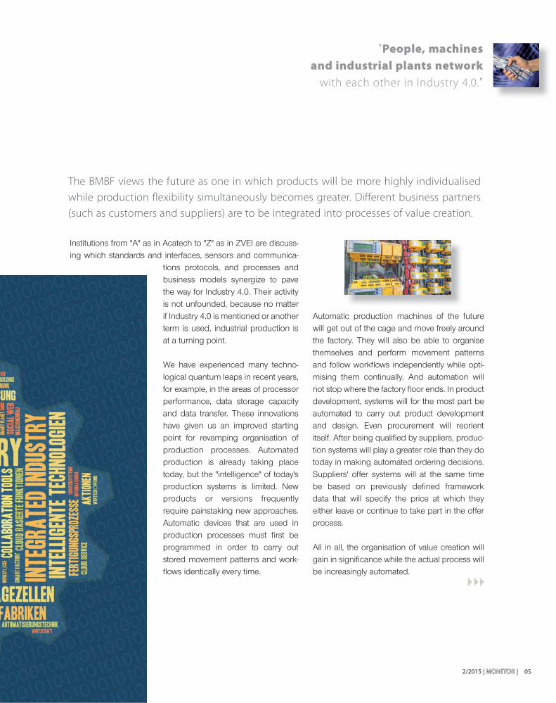
"People, machines and industrial plants network
with each other in Industry 4.0."

On 29 September 2015 at the General Electric (GE) Conference "Minds and Machines" in San Francisco, GE's fi rst Chief Digital Offi cer of the industrial division "Power & Water" presented the digital power plant. The fact that the industrial business of GE has a digital offi cer is remarkable in and of itself. It also expresses the signifi cance of digitisation in value creation. While it is becoming increasingly standard that products get a digital twin, the digital twin of an entire power plant, including all the component products from other manufacturers, such as turbines from rival Siemens, presents an entirely new dimension.
Digitisation gives energy suppliers an opportunity to recognise unfolding problems early on and take mea-sures to counter them.
This philosophy of prevention is also deeply anchored at Bender. Indeed, prevention can even be used as the generic term for describing what Bender has been pursuing for the last seven decades – monitoring insu-lation to recognise faults as early as possible in order to eliminate them before they become problems.
Bender products have proven themselves in produc-tion processes. They have guaranteed electrical safety for production workers, prevented electrical fi res caused by insulation faults and undesirable interrup-tions in production. In the future this will even be more important because the more automated production becomes, the greater will be its dependence on an uninterrupted power supply.
06 | MONITORMONITOR | 2/2015
F E AT U R E
Insulation faults can occur anywhere. Ageing, mechani-cal wear, compression, heat and dampness, etc., can all cause them. They can happen on cables, in generators, devices, machines and systems, generally, anywhere where there is an electrical current. In inverters, they can even happen in intermediate circuits and give system operators DC fault currents in an AC grid that only has safety technology suited to AC, rendering safety sys-tems for personnel ineffective.
Bender technology offers system operators the abil-ity to fi nd electrical insulation faults as they develop. System operators are then able to recognise a fault's causes before accidents, interruptions or fi res can occur. High-performance insulation monitoring devices in unearthed systems (IT systems) detect degradation in insulation in the megohm range if necessary, meaning long before an insulation fault occurs and is able to unleash its destructive power. By using them together with locating systems, operators even automatically
The logistics sector is a prime example for the mode of action of Industry 4.0

2/2015 | MONITORMONITOR | 07
receive a report about where the insulation fault is located. In an earthed TN system, a Residual Current Monitor (RCM) does this job. The resolution of an RCM is limited for physical reasons and restricted to locating asymmetrical degradation in insulation. As a rule, this still makes them suffi cient for use in production operations to ensure system and fi re safety. Equipment, however, that is being supplied by an earthed system, but may be inactive cyclically for about a minute or even longer can be monitored by offl ine insulation monitoring devices just as effi ciently as in an IT system.
Innovative insulation monitoring devices such as the iso685 or the RCMS460, but also the Power Quality Analysers of the PEM Series offer the required data interfaces for integration into production control or building management systems. Outstanding mea-surement technology coupled with particularly simple installation and operation makes them interesting for companies that are using Industry 4.0 for orientation as they develop their production. That is because the factory of the future will be dependent on status data – the more of it and more varied the better. Status data are the starting point for correlative algorithms that recognise patterns and make predictive behaviour possible. Because many production machines and systems are operated with electricity, they also express their "state of health" in electrical parameters. If, for no recognisable reason, a motor requires extra power for the same workfl ow, checking to see if wear and tear is the cause, for example, is called for.
The advantages of Bender technology do not only benefi t customers, but Bender itself in its own plants. The new facility at the headquarters in Grünberg, Hessen, has been operating for three years. Here the workpiece carrier uses RFID technology to com-municate with the control system. As it makes its way into existence, the item being produced fi nds its workstations by itself. All the production steps are documented, just as all components can be traceably
assigned to the product. Bender products continually monitor the state of the electrical system at about one thousand measurement points. This allows not only preventive maintenance but also unin-terrupted operation.
In addition to the many advantages, online monitoring also meets the requirement of insulation tests in accordance with DGUV Regulation 3, which may then be omitted due to higher-perfor-mance, permanent monitoring. The visual presentation that goes along with it allows simple interpretation of status reports.
Dr. Dirk Pieler, CEO
INFO
Interested readers are cordially invited to come to
Grünberg and see the technologies in action. How can an
operator of an electrical system – be it a complex plant or a
single machine – benefi t by using these systems? We would
be pleased to answer this question individually. Simply speak
to the Bender technical offi ce near you, or contact our head-
quarters. We look forward to your call!
" The factory of the future
will be dependent on status data
– the more of it and more varied the better."

| MONITORMONITOR | 2/201508
eCarTec Award 2015
NEWSWORTHY
On 19 October 2015 at eCarTec 2015 in Munich – the world’s largest international trade fair for e-mobility – Bender GmbH & Co. KG was awarded the Bavarian State Prize for Electromobility in the “Energy Storage & Infrastructure” category.
This was the seventh time MunichExpo Veranstaltungs GmbH had organised the eCarTec Award, which is unique in the world and seeks to promote the further development of electromobility. The Bavarian State Prize for Electro & Hybrid Mobility picks out the year’s best products, innovative technologies and exciting concepts. The fi nalists nominated for the four award cat-egories in 2015 were 21 submissions from companies and institutes from nine countries.
With the newly developed RCMB121-1 AC/DC sensitive residual current monitoring device, Bender GmbH & Co KG makes a considerable contribution to protecting people against dangerous electric currents in electric vehicles and was awarded the prize for the second time.
The device is used for fault current monitoring of AC charging stations for electric vehicles in which DC or AC fault currents of a magnitude continuously greater than zero can occur.
Residual currents can be caused in practice by insulation faults that occur, for example, due to defective cable insulation. In the worst case, people could suffer a dangerous electric shock. The device detects fault currents in the charging sta-tions or defects in the charging cables. Monitoring is carried out by an externally connected and shielded current transform-er. Here, the r.m.s. value is composed of the DC component contained in the residual current and the AC component below the cut-off frequency.
The reaction to detected faults by the residual current protec-tive device (RCD) type A in the electrical installation powers the system down and prevents accidents involving electrical power. When it is not certain whether an RCD is present in a building installation, the RCMB121-1 integrated into the IC-CPD takes over this safety function.
For charging mode 2, the RCMB121-1 residual current mon-itoring device offers a compact solution for use in a charging cable (IC-CPD) that can detect and evaluate DC fault currents (IΔn = DC ≥ 6 mA) and pulsating AC fault currents (IΔn = AC ≥ 30 mA). The sensor is very compact and can be used in two versions either for IEC or UL regimes. The curves for powering down are adjusted in the different versions to suit the requirements of the respective approval regime. Thus the device already fulfi ls the requirements of the new standard (IEC 62752) for mode 2 charging (IC-CPD), which is to apply from January 2017.
The new RCMB121-1 has all the prerequisites to be a part of the basic and safety equipment for the coming generation of charging stations for electric and hybrid vehicles widely predicted to arrive on the streets in the very near future.
Residual current monitoring in charging stations for electric vehicles
Bender receives award
Marita Schwarz-Bierbach
S-COM
The newly developed AC/DC sensitive residual current monitor RCMB121-1
F.l.t.r: Alexander Fürst zu Schaumburg-Lippe, Tanja Bülter, Dr. Ulrich Pütz – Vacucumschmelze, Robert Metzger, Winfried Möll - Bender, Franz Josef Pschierer
ABOUT ebee SMART TECHNOLOGIES:
Ebee Smart Technologies GmbH was founded in 2011 as a tech-
nological company for charging infrastructure. Its core product is
a charging point that is characterised by an especially compact
and modular structure, and which comprises all necessary func-
tions for the charging of electric vehicles in public spaces. Ebee
has already established partnerships with various renowned
names in the automotive industry and electric mobility, and the
market launch has successfully started in German and European
regions. For example, ebee has been nominated as the supplier
of street light charging points for the expansion of the charging
infrastructure in Berlin.
www.ebee.berlin
2/2015 | MONITOR | 09
Cooperation in development, manufacturing and sales of charging infrastructure products
N E W S W O R T HY
Dr. Henning Heppner
ebee Smart Technologies GmbH
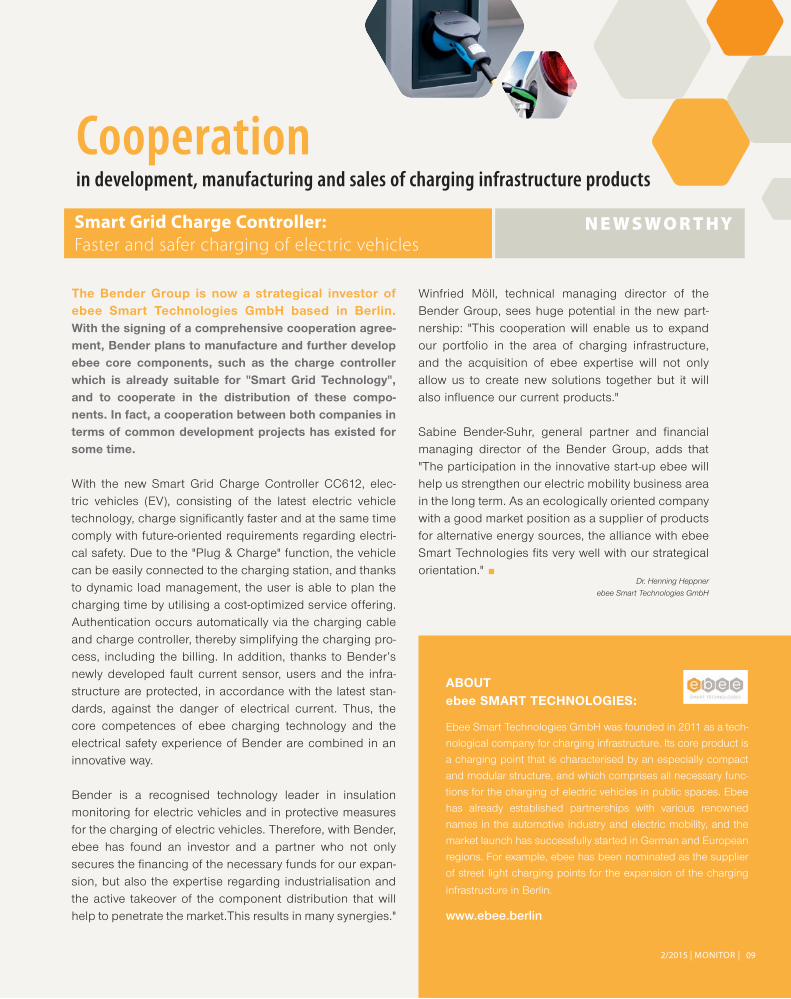
The Bender Group is now a strategical investor of ebee Smart Technologies GmbH based in Berlin. With the signing of a comprehensive cooperation agree-ment, Bender plans to manufacture and further develop ebee core components, such as the charge controller which is already suitable for "Smart Grid Technology", and to cooperate in the distribution of these compo-nents. In fact, a cooperation between both companies in terms of common development projects has existed for some time.
With the new Smart Grid Charge Controller CC612, elec-tric vehicles (EV), consisting of the latest electric vehicle technology, charge signifi cantly faster and at the same time comply with future-oriented requirements regarding electri-cal safety. Due to the "Plug & Charge" function, the vehicle can be easily connected to the charging station, and thanks to dynamic load management, the user is able to plan the charging time by utilising a cost-optimized service offering. Authentication occurs automatically via the charging cable and charge controller, thereby simplifying the charging pro-cess, including the billing. In addition, thanks to Bender’s newly developed fault current sensor, users and the infra-structure are protected, in accordance with the latest stan-dards, against the danger of electrical current. Thus, the core competences of ebee charging technology and the electrical safety experience of Bender are combined in an innovative way.
Bender is a recognised technology leader in insulation monitoring for electric vehicles and in protective measures for the charging of electric vehicles. Therefore, with Bender, ebee has found an investor and a partner who not only secures the fi nancing of the necessary funds for our expan-sion, but also the expertise regarding industrialisation and the active takeover of the component distribution that will help to penetrate the market.This results in many synergies."
Winfried Möll, technical managing director of the Bender Group, sees huge potential in the new part-nership: "This cooperation will enable us to expand our portfolio in the area of charging infrastructure, and the acquisition of ebee expertise will not only allow us to create new solutions together but it will also infl uence our current products."
Sabine Bender-Suhr, general partner and fi nancial managing director of the Bender Group, adds that "The participation in the innovative start-up ebee will help us strengthen our electric mobility business area in the long term. As an ecologically oriented company with a good market position as a supplier of products for alternative energy sources, the alliance with ebee Smart Technologies fi ts very well with our strategical orientation."
Smart Grid Charge Controller:
Faster and safer charging of electric vehicles

| MONITORMONITOR | 2/201510
Reliability of supply in the event of a fault and the protection against electric shock are central tasks in electrical energy supply. This will be
achieved by unearthed power supply systems (in short IT systems) with the respective
protection and monitoring devices. The new edition of the International and European
product standards IEC/EN 61557-8, -9 and -15 address the increased demands from
practical experience and from the new metrological capabilities.
In unearthed IT systems, an insulation monitoring device (in short IMD) has the task to signal when-ever the minimum insulation resistance RF level falls below a minimum value. IMDs according to EN 61557-8 can also be used to monitor offl ine TT, TN, and IT systems or loads. This has often
been proven in practice, e.g. to safeguard safety devices in the event of a fault or as a preventive measure, e.g. in fi re-extinguishing systems. The German edition DIN EN 61557-8 (VDE 0413-8) will be published in September 2015.
Clear marking of insulation monitoring devices according to EN 61557-8:2015
New standards for insulation monitoring devices (IMD)
2/2015 | MONITORMONITOR | 11
N E W S W O R T HY
The standard specifi es the requirements for operating IMDs that continuously monitor the insulation resistance to earth of unearthed AC IT systems with galvanically connected d.c. circuits with nominal voltages up to 1000 V a.c. as well as unearthed d.c. IT systems up to 1500 V d.c. independent from the measuring method.
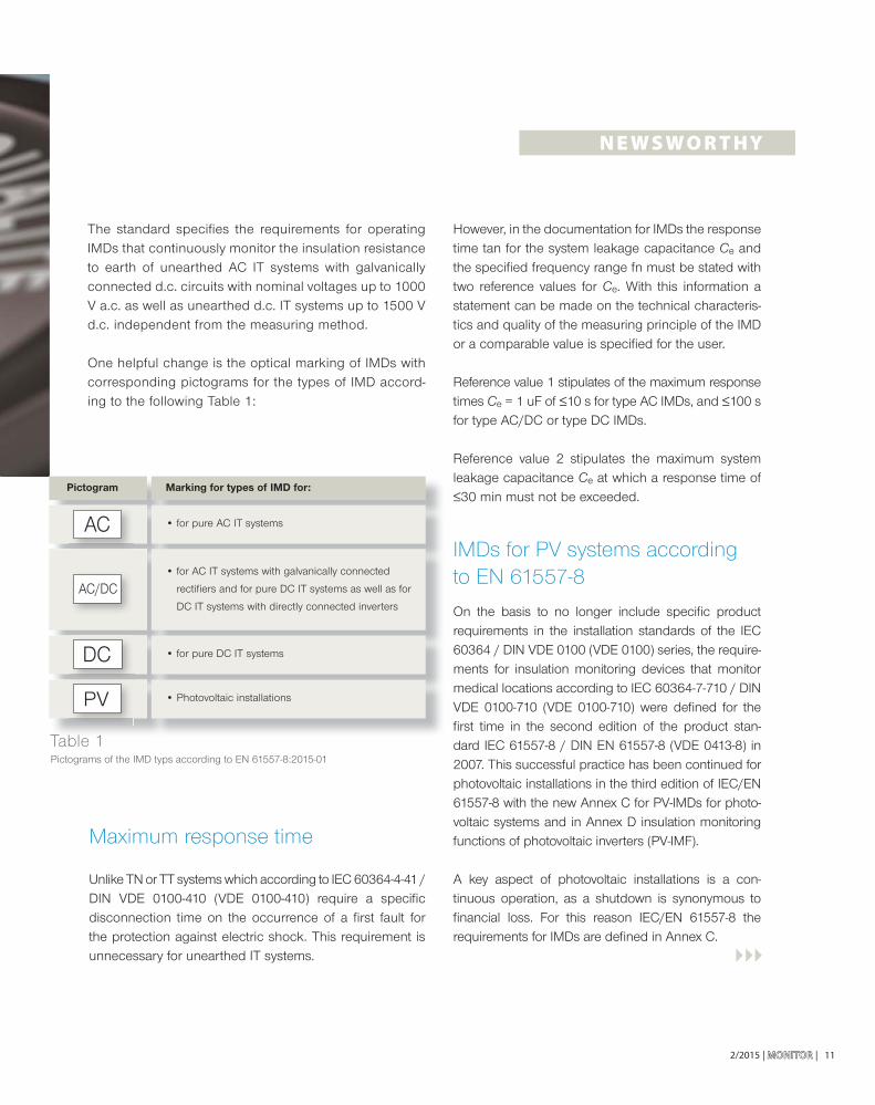
One helpful change is the optical marking of IMDs with corresponding pictograms for the types of IMD accord-ing to the following Table 1:
Maximum response time
Unlike TN or TT systems which according to IEC 60364-4-41 / DIN VDE 0100-410 (VDE 0100-410) require a specifi c disconnection time on the occurrence of a fi rst fault for the protection against electric shock. This requirement is unnecessary for unearthed IT systems.
However, in the documentation for IMDs the response time tan for the system leakage capacitance Ce and the specifi ed frequency range fn must be stated with two reference values for Ce. With this information a statement can be made on the technical characteris-tics and quality of the measuring principle of the IMD or a comparable value is specifi ed for the user.
Reference value 1 stipulates of the maximum response times Ce = 1 uF of ≤10 s for type AC IMDs, and ≤100 s for type AC/DC or type DC IMDs.
Reference value 2 stipulates the maximum system leakage capacitance Ce at which a response time of ≤30 min must not be exceeded.
IMDs for PV systems according to EN 61557-8
On the basis to no longer include specifi c product requirements in the installation standards of the IEC 60364 / DIN VDE 0100 (VDE 0100) series, the require-ments for insulation monitoring devices that monitor medical locations according to IEC 60364-7-710 / DIN VDE 0100-710 (VDE 0100-710) were defi ned for the fi rst time in the second edition of the product stan-dard IEC 61557-8 / DIN EN 61557-8 (VDE 0413-8) in 2007. This successful practice has been continued for photovoltaic installations in the third edition of IEC/EN 61557-8 with the new Annex C for PV-IMDs for photo-voltaic systems and in Annex D insulation monitoring functions of photovoltaic inverters (PV-IMF).
A key aspect of photovoltaic installations is a con-tinuous operation, as a shutdown is synonymous to fi nancial loss. For this reason IEC/EN 61557-8 the requirements for IMDs are defi ned in Annex C.
Pictogram Marking for types of IMD for:
• for pure AC IT systems
• for pure DC IT systems
• Photovoltaic installations
• for AC IT systems with galvanically connected
rectifi ers and for pure DC IT systems as well as for
DC IT systems with directly connected inverters
Table 1Pictograms of the IMD typs according to EN 61557-8:2015-01

| MONITORMONITOR | 2/201512
N E W S W O R T HY
The requirements for PV systems are complemented by Annex D that describes the requirements for the insulation monitoring function for PV inverters taking into account the standard IEC 62109-2 / DIN EN 62109-2 (VDE 0126-14-2). Requirements similar to those for a PV-IMD also apply here.
Devices for insulation fault location systems according to EN 61557-9
According to IEC 60364-4-41 / DIN VDE 0100-410 (VDE 0100-410), it is a requirement that in IT systems an insulation fault is eliminated within the shortest practicable delay. Particularly in complex and large installations however, this can become a very time consuming affair. Here, the usage of insulation fault location systems provides a solution; these devices locate the fault within a very short time and without shutting-down the installation.
IEC/EN 61557-9 describes the normative require-ments on insulation fault location systems that can locate insulation faults in unearthed a.c. IT systems or a.c. IT systems with galvanically connected d.c. circuits with nominal voltages up to 1000 V a.c. as well as unearthed d.c. IT systems up to 1500 V d.c.
An IFLS (Insulation Fault Location System) must be able to locate both symmetrical and asymmetrical insulation faults in an unearthed IT system. The local-isation message indicates where the outgoing circuit or area with the insulation fault is.
From a metrological point of view the possible high system leakage capacitances and the dynamic voltage changes represent a challenge for the IMD. Therefore, even under the effect of the fl uctuation in the DC voltage as shown in Figure 1, an IMD may
• not trigger a false alarm;
• detect and signal insulation faults within the spec-ifi ed response time;
• not erroneously clear the alarm message from an alarm status;
• clear an alarm message if the insulation fault is below the specifi ed limit.
F I G . 1
Dynamic reference characteristics of photovoltaic DC according to EN 61557-8

2/2015 | MONITORMONITOR | 13
SUMMARY
Seven years have passed since the last publication of the product standards for insulation
monitoring devices and equipment for insulation fault location in IT systems. With the new
editions of IEC 61557-8 and IEC 61557-9 the rapid technological progress in the area of
insulation monitoring for unearthed power supplies (IT systems) has been addressed as has
the trend of describing more product requirements in independent standards. These also
include the special requirements on the functional safety of these devices in accordance
with IEC 61557-15.
Dipl.-Ing. Harald Sellner, T-N
Dipl.-Ing. Dieter Hackl, T-MIS
STANDARD REFERENCES
IEC 60364-1Low-voltage electrical installations - Part 1: Fundamental principles, assessment of general characteristics, defi nitions
DIN VDE 0100-100 (VDE 0100-100):2009-06Errichten von Niederspannungsanlagen – Teil 1: Allgemeine Grundsätze, Bestimmungen allgemeiner Merkmale, Begriffe
IEC 60364-4-41Low-voltage electrical installations - Part 4-41: Protection for safety - Protection against electric shock
DIN VDE 0100-410 (VDE 0100-410):2007-06Errichten von Niederspannungsanlagen – Teil 4-41: Schutzmaßnahmen - Schutz gegen elektrischen Schlag
IEC 60364-7-710:2002Electrical installations of buildings - Part 7-710: Requirements for special installations or locations - Medical locations
DIN EN 60364-7-710 (VDE0100-710):2012Errichten von Niederspannungsanlagen - Teil 7-710: Anforderungen für Betriebsstätten, Räume und Anlagen besonderer Art – Medizinisch genutzte Bereiche
EN 61557-8:2015-01 and DIN EN 61557-8 (VDE 0413-8), Elektrische Sicherheit in Niederspannungsnetzen bis AC 1 000 V und DC 1 500 V – Geräte zum Prüfen, Messen oder Überwachen von Schutzmaßnahmen – Teil 8: Isolationsüberwachungsgeräte für IT-Systeme.
IEC 61557-8:2014-12Electrical safety in low-voltage distribution systems up to 1 000 V a.c. and 1 500 V d.c. – Equipment for testing, measuring or monitoring of protective measures – Part 8: Insulation monitoring devices for IT systems
EN 61557-9:2015-01 and DIN EN 61557-9 (VDE 0413-9)„Elektrische Sicherheit in Niederspannungsnetzen bis AC 1 000 V und DC 1 500 V – Geräte zum Prüfen, Messen oder Überwachen von Schutzmaßnahmen – Teil 9: Einrichtungen zur Isolationsfehlersuche in IT-Systemen.
IEC 61557-9:2014-12Electrical safety in low-voltage distribution systems up to 1 000 V a.c. and 1 500 V d.c. – Equipment for testing, measuring or monitoring of protective measures – Part 9: Equipment for insulation fault location in IT systems
DIN EN 61557-15 (VDE 0413-15):2014-10Elektrische Sicherheit in Niederspannungsnetzen bis AC 1 000 V und DC 1 500 V – Geräte zum Prüfen, Messen oder Überwachen von Schutzmaßnahmen – Teil 15: Funktionale Sicherheit in IT-Systemen und in Einrichtungen zur Isolationsfehlersuche in IT-Systemen
IEC 61557-15Electrical safety in low-voltage distribution systems up to 1 000 V a.c. and 1 500 V d.c. – Equipment for testing, measuring or monitoring of protective measures – Part 15: Functional safety requirements for insulation monitoring devices in IT systems and equipment for insulation fault location in IT systems
IEC 61508Functional safety of electrical/electronic/programmable electronic safety-related systems
IEC 62109-2Safety of power converters for use in photovoltaic power systems - Part 2: Particular requirements for inverters

| MONITORMONITOR | 2/201514
Insu
lati
on
mo
nit
ori
ng
de
vic
e I
SO
ME
TE
R®
iso
PV
16
85
PF
R
Astonishingly easy fault location in large-scale photovoltaic installations
The devices isoPV1685 and isoPV1685PFR have been successfully in use for insulation monitoring on large-scale photovoltaic installations up to about 3 megawatts and up to DC 1500 V for several years. All the more astonishing, therefore, when custom-ers who already know and appreciate the role of these devices in insulation monitoring are very sur-prised to see how quickly and easily they can locate faults, even in large-scale PV installations.
Finding insulation faults quickly in photovoltaic systems is more important than it is in other indus-trial IT systems. The main reason is that – with the current state of art – the protective measure “auto-matic shutdown of the power supply” in accor-dance with Section 411 of DIN VDE 0100-410 (VDE 0100-410):2007-06 cannot be implemented on photovoltaic generators in PV installations. The permitted protective measure for this type of appli-cation is “doubled or increased insulation”, as described in Part 412 of DIN VDE 0100-410 (VDE 0100-410):2007-06.
In the absence of other measures, the mainte-nance of doubled or increased insulation in pho-
tovoltaic generators is therefore the only protection against electric shock. An insulation fault in one of these systems could present a high risk of loss of life.
Operators of photovoltaic installations are therefore obliged by the provisions of the standard to rectify any insulation faults as soon after their discovery as is practically possible. In the event of a claim for damages, the speed of reaction of the operator is compared against the requirement to act “as quickly as possible”. This assessment takes into account the present state of art, which is described in standard DIN EN 61557-9 (VDE 0413-9) and embodied by the isoPV1685PFR device in the fi eld of large-scale PV installations.
With the isoPV1685 recently achieving compliance with UL 1998 and IEC60730-1, the way is now open for its use in large-scale PV installations intended for the American and Canadian markets. If the demand is high enough, the iso-PV1685PFR will also be put forward for similar certifi cation.Another new development for both versions of the device is their compliance with the new Annex C “Insulation monitoring devices for photovoltaic power supply systems” (PV-IMD) of the updated standard DIN EN 61557-8 (VDE 0413-8):2015-09. According to the latest version of the standard, the sources of interference anticipated in PV installations should not crit-
INNOVATIVE P RO D U C TS
CO M PAC T – I N N OVAT I V E – S A F E
The ISOMETER® isoPV1685PFR insulation monitoring device provides effi cient fault location
up to AC 1000 V/DC 1500 V

2/2015 | MONITORMONITOR | 15
Dipl.-Ing. Dieter Hackl, T-MIS
Dipl.-Ing. Manfred Geiss, T-MIS
ically affect the monitoring function of insulation monitoring devices complying with the latest standards. Devices meeting the requirements of DIN EN 61557-8 (VDE 0413-8):2015-09 Annex C are identifi ed with the pictogram.
The pulse current generator integrated into the isoPV1685P-FR allows the service technician to troubleshoot the system without having to interfere with any live parts. This reduces risk to a great extent. In the event that an insulation fault is
signalled by the insulation monitoring device, the internal locating current injector is activated manually or automati-cally without changes to the PV installation. Both the faulty string and the faulty module in the large PV installation can then be found very quickly with the aid of an already installed and/or portable fault locator (e.g. EDS195P), without the need to take parts of the installation out of operation to locate the fault. By using the isoPV1685PFR variant with inte-grated fault location function, fi ve-fi gure sums for fault loca-tion by electricians and the related downtimes can be saved.
Dipl.-Ing. Dieter Hackl, T-MIS
Dipl.-Ing. Manfred Geiss, T-MIS
The FP200 display and operator unit adds the option of front panel mounting
to the iso685 device family.
Three diff erent mounting options retain the same functionality and operation
In addition to DIN rail mounting, which was the only mounting option available for all iso685 device variants with display (-D), the newly available FP200 display and operator unit allows front panel mounting for all iso685 device vari-ants without display (-S).
Now two further mounting options offer more fl exible inte-gration of the devices into the front of a control cabinet.
Version 2: Display in the control cabinet front
The FP200 display unit is mounted into the front using retaining brackets. The basic device iso685-S, iso685-S-B or iso685-S-P without display is attached to the mounting plate or the DIN rail and connected to the FP200 by the supplied RJ45 patch cable. This allows the device’s display to be integrated into the control cabinet front without having
to route the network connection operating at up to 1,000 V to the control cabinet front. Despite the different mounting methods, the device functions and operates exactly like a device with display.This mounting option is also available as a “W” version for special load conditions. A transparent front cover keeps IP65 available.
Version 3: Display on the rear
Retrofi t applications have the option of attaching a basic device iso685-S, iso685-S-B or iso685-S-P on the rear of the FP200, which is integrated into the control cabinet door. Suitable adapters are available for front panel mount-ing, which makes replacement of existing IRDH375 and IRDH575 installations very easy. This mounting variant is currently not (yet) available as a “W” version.
Dis
pla
y a
nd
op
era
tor
un
it
FP
20
0
p
INNOVATIVE P RO D U C TS

Unique fast tripping in IT systems with small Ce
Insulation monitoring devices are mainly used in IT systems (unearthed networks) to carry out the protective measure “automatic shutdown of the power supply” as described in Section 411 of DIN VDE 0100-410 (VDE 0100-410):2007-06. The special feature of this form of network: the power supply is shut down only after a second fault occurs. Thus this protective measure provides protection against electric shock.
There are, however, other protective objectives in applica-tions that also require a fast shutdown of the power supply on the fi rst insulation fault in an IT system.
One example of this is applications in mines. If a second fault occurs in this environment, it can lead to arcing. In these circumstances, the resulting risk from the possible presence of fi redamp (a specifi c mixture of methane and air, with danger of ignition) is not acceptable and must be avoided.
A further example is a protective device for CDV reactors in the production of silicon. In some circumstances, the reactor is in danger of being destroyed and therefore a fast shutdown is required. These circumstances include the breakdown of the insulation of the electrical contacts provided by the reactor fl oor, silicon fragments falling in
the area of the electrical feed entry point, or broken off or toppling heating elements that fall against the reactor wall or trigger a chain reaction by contacting or damaging other heating elements.
Until recently the types of fast shutdown protective devices integrated into IT systems were based on residual voltage and/or residual current measurement.
However, the methods used before did not detect symmet-rical faults. In addition, they were mostly unsuitable for sys-tems in which frequency converters or other switched power supplies were present. The used devices were therefore “blind” in this type of application.
On the contrary, in the same applications, the iso1685FR can “see” very well thanks to the new SSCP measuring method (patent applied for) developed by Bender. This process rec-ognises symmetrical faults. There is now nothing to prevent the use of switched power supplies or frequency converters in combination with fast shutdown protective devices.
Dipl.-Ing. Dieter Hackl, T-MIS
Dipl.-Ing. Manfred Geiss, T-MIS
The ISOMETER® iso1685FR
insulation monitoring device
allows a protective device that
can execute an automatic shutdown
of the power supply in < 150 ms
to be fi tted in 3(N)AC 5 kV 50/60 Hz
IT systems.
16 | MONITORMONITOR | 2/2015
Insu
lati
on
mo
nit
ori
ng
de
vic
e I
SO
ME
TE
R®
iso
16
85
FR
INNOVATIVE P RO D U C TS
CO M PAC T – I N N OVAT I V E – S A F E

NEW
172/2015 | MONITORMONITOR |
Mobile measuring case for network analysis
The new mobile measuring case PEM735: a class A analyser for mobile use
Do you remember when a single percussion drill could cripple the television reception in a whole apartment block?
Now, as a private user, you can normally rely on being able to use a whole range of different electrical devices in your home without expecting interference between the devices. This is thanks to extensive rules and standards on electro-magnetic compatibility (EMC).
In the private sector, the energy supply situation is very convenient when it comes to voltage quality: on one hand, the emissions from the electrical devices connected differ hugely; on the other hand, the power required by individual loads is very low in relation to the nominal output of the source (local network transformer). The operating current for a single 25 W charger can barely register relevant inter-ference to the network voltage on a 630 kVA transformer station.
The situation is a little different in the industrial and com-mercial sector, where high-performance loads (e.g. frequen-cy converters) or multiple small devices of the same type are used. Their individual potential to have an infl uence on the network voltage is also small, but the interference adds up at the connection point. Several hundred small devices with the same operating current can defi nitely cause pro-blems with the network voltage.
Who is responsible for this kind of interference?
The plant operator is al-ways responsible for dealing with the interference quickly, in his own interests, if nothing else. However, he is also bound to ensure that the compatibility level for EMC (i.e. the voltage quality) is complied with in his electrical system. Many operators of electrical systems only become aware of the issue when they are facing a problem with EMC or voltage quality. A permanently installed network analyser uses historical data to identify the causes of problems in the electrical system (e.g. failures or disturbances).
The new PEM705 measuring case for mobile use makes it possible to assess the voltage quality of an electrical system and record voltage and current paths without additional installation to the electrical system. In the best-case scenar-io, the result of this measurement can deliver immediate indicators as to the cause of the problem.
After the measurement comes the measurement
As well as removing the cause of the problem or setting up corrective measures, a network analyser should be per-manently installed to ensure the electrical system operates without problems. This means problems can be identifi ed as they arise and faults are recorded the very fi rst time they occur. The Bender PEM735 has the same operating envi-ronment for the permanently installed measuring device and the mobile case solution, so it is easy to fi nd your way around.
Th
e n
ew
Mo
bil
e m
ea
suri
ng
ca
se P
EM
73
5
The new mobile measuring case PEM735:
Dipl.-Wirt. Ing. Michael Faust, T-MTS
INNOVATIVE P RO D U C TS

18 | MONITORMONITOR | 2/2015
Ch
arg
e C
on
tro
lle
r C
C6
11
an
d C
C6
12
Charge Controller
CC611 and CC612
With an ever-increasing awareness of the need for a cleaner world combined with increasing demands for a low-cost, high-performing reliable and effi cient alternative to the petrol or diesel engine, the future of the electric vehicle looks very promising. As the number of electric vehicles on the roads continues to grow, so too does the infrastructure needed to ensure that fi nding a charging station or charging point is not a problem.
The costs of installing a charging point are also fall-ing thanks in part to technological developments, but challenges still remain. With little available space and a
vehicle electrical system that must fulfi l the demand-ing industrial requirements specifi ed by
IEC61851, IEC60364, iso15118, iso17409 and the Open Charge
Point Protocol (OCPP), mode 3 AC charging points are under
particular pressure because the installation and charge point costs are simply too high to be economically viable for a provider [1]. Today’s AC charging points are mainly systems
with expensive and sensi-tive RCD protection devices
(type B FI circuit breaker). This allows today’s cars to charge at
many different charging stations. However, the back-end communica-
tion may be different, allowing some cars to charge only at specifi c charging stations where the E-Mobility Provider (EMP) and the Charge Point Operator (CPO) are the same. With its scalable highly integrated CC611 and CC612 charge controllers, Bender is addressing these issues.
CC611 – Small and smart
As the main component of a charge point, the CC611 is designed for use in electric vehicle (EV) charging sta-tions in, for example, wall boxes or street light charging points. It controls electric vehicle charging and enables a setup that is in accordance with IEC 62196, IEC 61851-1 and IEC 61851-22. As well as being compatible with current electric vehicles on the market, the charge controller features:
• Standard OCPP Implementation with full OCPP Remote functionality
• Compatible with single and three-phase power systems
• Support of 2.5G Edge and 3G UMTS mobile networks
• USB extension port for WiFi home applications.
The CC611 is characterized by its compact design and size that in turn enables intelligent, small and cost effective charging points. To enable the charge con-troller to communicate, a back-end system is required. Given that most backend providers strictly adhere to the
[1] W.Möll, R. Weyrauch, 2015 „Challenges of AC Charging Points“, Elektrik/Elektronik in Hybrid- und Elektrofahrzeugen und elektrisches Energiemanagement VI, Pages 502-510
– anywhere and at anytime
CHARGING
As a manufacturer of insulation monitoring devices for
unearthed DC drive systems in electric vehicles, Bender is now
expanding its e-mobility business to include compact, intelligent and cost- effective charge controllers.
ing industrialIEC6185
iso174Po
A
(allo
manyHowever,
HAINNOVATIVE P RO D U C TS

192/2015 | MONITORMONITOR |
Open Charge Point communication protocol (OCCP), the charge controller is OCPP 1.5 complaint and can operate with the backend implementations of providers such as Vattenfall, Bosch, NTT and DRIIVZ.
The charge controller can be operated as an "always on" system that is always connected to a mobile network and it supports 2.5G Edge and 3G UMTS mobile networks. Connectivity for online operation requires a SIM card, the PIN number of which can be confi gured via an internal confi guration web interface. The APN settings for the card can also be confi gured via an internal confi guration web interface.
One of the two USB ports serves as a confi guration inter-face and can be connected to a conventional laptop, PC or tablet computer with a normal USB host interface via a micro USB cable. This interface allows the device to be confi gured locally as well as enabling software updates. The other USB port provides a way of connecting the CC611 to an existing Ethernet/WiFi network. For billing purposes, the CC611 can interface with an electronic household meter.
To ensure reception in all areas, the CC611 also features an externally mounted antenna for 3G communication. User interaction is facilitated using an RFID module, which consists of an RFID card reader and LEDs. Charging is initiated by either holding a valid RFID card close to the reader or remotely by the backend system via OCPP.
In offl ine operation, the charge controller can optionally allow charging without authorization or it can authorize users based on RFID and a local white list of authorized RFID cards.
CC612 – meeting future needs
Future charge point systems will need Power-Line-Communication (PLC) to allow “Plug & Charge” functionality as well as load man-agement or “Vehicle to Grid (V2G)” applications. However, the new IEC61364-7-722 safety standard allows the use of a cheaper type A RCD device (standard FI circuit breaker) when additional DC 6mA current protection is used. The CC612 charge controller has been designed to satisfy the above requirements.
Similar to the CC611, the CC612 has been extended to include an internal antenna, optional UL2231 CCID 20 sensing, an optional integrated 3G modem and an optional integrated AC/DC sensitive residual current monitoring (RCMB) device for AC charge point monitoring. Monitoring takes place via an externally connected and shielded current transformer which is connected to the CC612.
Fig. 1
L1
L2
L3
N
PE
12 V DC
A2
L
N+12 V 0 V
A1
A2
CC611 charge controllerContactor
D4
L1
L2
L3
N
V
CC611
1
2
3G
USB
1
DEB
UG
SIM
ANTENNE
B1 B4
C1 C4
D1 D4
Meter
RFID
(USB
2)
A4A1B
C
D
A
CP
PE
Charge point
CP PP
L1
L2L3
N PE
C2 C3 C4
2k2
C10 V
Optocoupler(cathode)
A1 A2 A3 A4B1 B2 B3 B4
Optocoupler(Anode)
B
C
CP
2k2
12 V0 V
D1 D2 D3 D4A A
DB B
Relay K1( to 12 V supply)
Relay K1 (to contactor A1)
Optocoupler(Cathode)
Optocoupler(anode)
Optocoupler(cathode)
Relay K2 Relay K2
2k2 A
Type 2
D2
Dr. Catherine Körbächer, T-MISDipl.-Ing. Frank Mehling, T-MIS
Fig. 2
EMH eHzSmart meter
CP PP
C2 C3 C4
2k22k2
L1
L2
L3
N
PE
12 V DC
C1
A2 A3
L1
L2L3
N
IR mod
ule
kWh
2 4 6 N
1 3 5 N‘
H
L
N
+12 V 0 V
2 4 6 8
1 3 5 7
A1
A2
C2
C3
C1
Mennekes (Type 196521)
Kuster ZSB (S 075-005-001)
Actuator **
Mennekes (Type 30537-A)
Mennekes actuator
(Type 196521)
FCT Group (FXL12S1-4409)
** Different actuators are supported.
0 V
P.3 (+)P.1 (2-ring from actuator)
Optocoupler(cathode)
C
D
B
P.3 (-)
A1 A2 A3 A4B1 B2 B3 B4
Optocoupler(cathode)
P.1 (+)
B
C
CC611 charge controller
A
PPCP
2k2
12 V0 V
Type 2 socket
Contactor D4
L1 L2 L3 N
PE
M
P.3
P.1
P.2
-
+
D1 D2 D3 D4
A A
DB B
Relay K1( to 12 V supply)
Relay K1 (to contactor A1)
Optocoupler(anode)
Optocoupler(anode)
Optocoupler(cathode)
RFID Module
V
Disconnecting switch
C
Sensor (P.2)
P.2 (-)
Yellow wire
Yellow wire
Green wire
Green wire
White wire
Brown wire
Brown wire
Red wire
Relay K2 Relay K2
B1 B4
C1 C4
D1 D4
A4A1
Meter
RFID
Wiring diagram for a charge point with a type 2 socket
Wiring diagram for a charge point with a cable and a type 2 plug

20 | MONITORMONITOR | 2/2015
Legislation and professional associations are con-stantly stressing how important it is to ensure electri-cal equipment can be safely handled and operated at work. The high requirements relating to medical products in particular call for them to be safe – for patients, users and third parties, e.g. visitors.
The “Bender tester” has been a byword for quality and durability in the fi eld of fully automatic electrical safety testers for more than 30 years. Now with the new UNIMET® 810ST, the market welcomes the third generation of the operable UNIMET® 800ST safety tester, which, in accordance with the standard, stores the “fi rst-measured value” as a reference value for later comparisons.
The latest model, the UNIMET® 810ST, has a new PC module capable of even higher performance. Thus the user has more RAM memory available for stor-age. The device is now even more stable thanks to the new software version 3.20 and a system update to Windows CE 6.0 RC3.
The safety tester has been redesigned and sports a new look. The bag has more room for storing test probes and a side pocket for e.g. a scanner.
In addition, the UNIMET® 810ST complies with a further standard: IEC 61010-1 for testing laboratory equipment, of course with a standard-compliant 25 A locating current as required by IEC 60601-1.
The UNIMET® 810ST is the only safety tester in the world to allow standard-compliant testing with a 25A locating current – quick, convenient and effective.
Other advantages for the user include the 36-month cali-bration interval and a 36-month warranty. This means lower operating costs over several years.
The other advantages of the UNIMET® 810ST are:
• Windows user interface for easy operation and use
• User-defi nable test procedures
• Filter functions for fi nding data quickly
• Test schedule management
• Multi-client capability
• Catalogue systems
• Data transfer and storage through Control Center
• Automatic, semi-automatic or manual test procedures
• User-defi nable visual, electrical and functional tests.
Sa
fety
te
ste
r U
NIM
ET
® 8
10
ST
Worldwide safety for medical electrical devices
The new UNIMET® 810ST
safety tester
Karl-Heinz Rein, T-SCT
INNOVATIVE P RO D U C TS

212/2015 | MONITORMONITOR |
are smarter togetherBender devices
Monitoring the safety of electrical installationsMonitoring the safety of electrical installations
In the simplest case, the devices give local warnings if electrical safety ceases to be
maintained. For many years, Bender has also produced devices for systems that can transmit
alarms, measured values and parameters to remote devices. New possibilities for the acquisition
and processing of large volumes of data and new concepts, such as Industry 4.0 or the
Internet of Things, are leading to the development of new applications in this fi eld. Electrical
parameters are data that can be analysed by various applications and considered together
with data from other sources. In this case, safety is still a very important aspect, but only one
among many. A wide range of applications work with these data and link them to other phys-
ical parameters to create a complex system with all types of data sources and sinks and a
correspondingly wide choice of means of communication.
Bender devices are used to monitor the safety of electrical systems.
INNOVATIVE P RO D U C TS

| MONITORMONITOR | 2/201522
A system is much more than the sum of all its parts. These systems offer new possibilities such as:
• Fault isolation by analysing data from various sources
• Savings from not having to install measurement points, especially for retrofi ts
• Improved forecasting models, e.g. through long-term monitoring
• Analysis of correlations between different physical parameters for determining the causes of faults.
Combining Bender devices into an intelligent system
The basic requirement is effi cient communication between the devices and sensors. The ability to communicate alone is of course not enough. In order to communicate effectively, every system com-ponent must be able to communicate selectively. Each device simply communicating with every other device does not help in this. In addition, the devices must react to the actual situation, e.g. the operational state of the system, the ambient conditions and the time of day.
What else is required for these components to work together?
• The medium (“BUS”), electrical wires, glass fi bre, wireless solutions
• The architecture of communication. This includes:
− Master-slave, i.e. a master device polls all the other devices in cycles. Advantage: robust, simple, disadvantage: the master must be designed with redundancy so that its failure does not bring down the whole system
− Peer-to-Peer, all devices can communicate with one another. Advantage: robust and fl exible, disadvantage: complex,
• The protocols, i.e. the agreement on one language
Protocols have spread in regions, industries and applications to different extents e.g. Internet: TCP, UDP/IP, fi eld bus level: Modbus, Profi bus, CAN and many other proprietary protocols.
• The semantics, i.e. an agreement about the con-tent or the meaning of the exchanged messages.
With its devices and communication modules, Bender can offer several fl exible solutions. Earlier Bender devices used the BMS* protocol and con-nected to other protocols through gateways. The basis of the BMS bus is the RS-485 interface as a physical layer over two-wire cables and Bender’s master-slave protocol with Bender’s optimised syn-tax and semantics.
In the future, Bender will support IP-based commu-nication directly, without giving up the convenience of the BMS. Thereby, use can be made of the Internet infrastructure, wherever it is available.
INNOVATIVE P RO D U C TS
*Bender Measuring Device Interface

2/2015 | MONITORMONITOR | 23
The Bender IP-based communication solution is BCOM
That means:
• Standard protocols where this is possible, e.g. IP, UDP, TCP, DHCP, DNS, NTP, JSON, ....
• and specifi c add-ons to increase effi ciency and ease of operation.
− Addressing
− Auto-discovery
− Alarming
• Plug and playi.e. no tiresome network confi guration
• Scalable topology
− From no communication to full networking
− From two up to 64,000 devices in a single system
− No server or master necessary, no polling
• Integration of fi eld bus devices, including those from third party manufacturers, via simple proxies.
They feature a web interface for displaying all the sys-tem states, providing customer-defi ned visualisations and displaying a graphical representation of all saved results and data logger contents. In addition to the use with all communication-enabled Bender devices, irrespective of the bus system (BMS, BCOM or Modbus), the system also supports simple integration of third-party devices via the Modbus. The ability to generate individual texts and e-mail messages when alarms occur allows the greatest possible customisation of the requirements of each indi-vidual system.
The gateway function permits external applications to be connected, e.g. to a control station or to a building man-agement system.
The available functions also include quick, simple parameter setting of all the Bender devices assigned to COMTRAXX® condition monitors and the report function to document, save and restore the settings.
By connecting through the COMTRAXX® series condition monitors, the huge versatility of today’s products is ready for use in the advanced intelligent systems of tomorrow.
The new series iso685 ISOMETER® is one of the fi rst devices to provide native support to the new effi cient BCOM communications protocol. More Bender protective devices will follow.
The fi rst BCOM solutions from Bender are already available with new devices in the COMTRAXX® series, COM465IP, COM465DP and CP700 V2.0. These are condition monitors with integrated gateway functions for incorporating communication-enabled Bender devices into the Ethernet TCP/IP networks.
Dipl.-Ing. Joachim Wagner, T-SCT
Dipl:-Ing. Friedhelm Dalitz, T-SCT

24 | MONITORMONITOR | 2/2015
Insulation monitoring devices manufactured by Bender GmbH & Co. KG are used in many parts of the transport network to raise safety levels. In railway
engineering, many of these devices are installed in key items of infrastructure such
as signal boxes. The limit values for these systems are monitored in accordance
with regulations such as Corporate Directive 892 issued by Deutsche Bahn Netz
AG (DB Netz).
New ideas for using data from insulation monitoring devices in the railway fi eld
In practice, the response or alarm value for the insulation resistance of cable systems in signal boxes is about 30 kΩ. Corrective or counter measures have to be taken if the resis-tance falls below this value. Unfortunately, no subsequent analysis of limit value observa-tions takes place, even though the devices usually have the interfaces for data output.
Data logger collects values
DB Netz, Bender and Deutsche Zentrum für Luft- und Raumfahrt e. V. (DLR) have set up a joint project to develop a prototype system to assess the potential of continuously monitoring these measured values. As part of this project, a data logger devel-oped by Bender has been installed in the signal box at Plattling (Bavaria) (Figure 1). The data logger records the individual measured values from the RS-485 interface and makes them available as a data fi le for further analysis. The RS-485 interface is parameterised in “isoData” mode to allow the necessary uni-directional communication for retrofi tting. The data logger must operate free of feedback.
The availability of this data opens up several options for the user.
DatenloggerDatenllogger
TECHNICAL APPLICATION

252/2015 | MONITORMONITOR |
cisely with heavy rain of 12l/m2. In the light of this information, engineers can come up with theories and derive empirical values about how robust a system is, for example, against heavy rain. Once this is known, forecasting models can be created and, for example, used to predict and therefore better anticipate malfunctions using the weather forecast. At the same time, this also increases the understanding of how the system reacts to outside infl uences.
The third advantage is that, in addition to sporadic effects, which are mostly traced back to external infl uences (such as the weather), it would also be possible to observe long-term degradation processes. These arise through constant wear on the system or permanent loading. Figure 3 shows a model of this [2]. If this type of degradation can be monitored, the operator can use the informa-tion and gain some advanced warning of a future failure. He may then use this period of prewarning to work out the optimum time for re-investment before eventually renewing or repairing the system.
Better and more objective tracing of malfunctions
The fi rst advantage is that malfunctions can be retrospec-tively analysed. When a malfunction occurs, the event can be more precisely and objectively recorded. For example, if a short-term drop below the limit value occurs and then disappears after a few seconds, this triggers the alarm and calls out the maintenance engineer. By looking at the data after the event, it may be possible to identify the cause of the malfunction, which had disappeared by the time the repair team arrived. From an analysis of the time of occurrence and the duration of the event, and, if possible, the state of the system at the time, the cause can be identifi ed. The second advantage is that the data can be combined with other information, e.g. weather or operational data. Figure 2 shows an example based on real data, in which a drop to an extremely low value was found to coincide pre-
Fig. 1 Data logger on the RS-485 interface of a Bender ISOMETER® IRDH265 in Plattling
Fig. 2Change of insulation resistance as a result of heavy rain
Onset of heavy rain with 12 l/sqm rainfall
Fig. 3
Model of the information advantage gained from continuous monitoring after [1]
[2] Wolfgang Hofheinz: “Protection technology with insulation monitoring!”, VDE Series 114, pages 151-154 (in German)
[1] www.Bender-de.com: “Product overview: ISOMETER® – Insulation monitoring devices, ISOSCAN® – Insulation fault location systems EDS”, page 4, http://www.bender-de.com/fi leadmin/products/b/e/ProductOverview-Isometer_PROSP_en.pdf

26 | MONITORMONITOR | 2/2015
transmission interfaces using gateways. The methods and equipment for this joint project have been so smoothly inte-grated into the DB Netz strategy that Bender and its products are already well placed to take further part in its customer’s innovative projects. DLR is also in the position to contribute to the project by transferring its experience in various appli-cations, for example, switch points or superstructure diagno-sis, gained from many years of assessing railway systems.
Empirical data for better understanding and prevention
The availability of this data gives the oper-ator a better understanding of his system and therefore the option to change from a reactive (reacting to reported failures) to a preventive maintenance strategy. DB Netz has also seen the possibilities offered by this idea and has been working for some time on a diagnosis platform, known as DIANA, for collecting and processing diag-nostic data from its infrastructure out in the fi eld. DB Netz already has a large number of ISOMETER® model IRDH265 insulation monitoring devices installed in many of its signal boxes. Adding a data logger to these for this purpose would be relatively easy.
Furthermore, future device generations will not only recognise different and more accu-rate types of measured data, but also sys-tematise the method with standardised data
Fig. 4Raw data from insulation measurements dated 1 February 2015
Fig. 5Raw data with automatic peak detection (blue points)
TECHNICAL APPLICATION

272/2015 | MONITORMONITOR |
"Future device generations will not only recognise different and more accurate
types of measured data, but also systematise the method
with standardised data transmission interfaces using gateways"
Prognoses through visible peaks
In addition to weather effects, other phenomena can be observed and investigated in the data. Figure 4 shows the measured data from 1 February 2015. The eye is immedi-ately drawn to the instantaneous peaks in the measured values. These appear to highlight a problem that is not yet serious enough to cause the values to drop below the fail-ure limit, but could lead to potential malfunctions. These peaks could be detected automatically using a wavelet transformation, as can be seen in fi gure 5 (blue points). If the number of peaks per day is counted , it can be used to reveal a trend as shown in fi gure 6. The number of peaks decreases in summer, which indicates that the system is likely to be more robust at that time of the year. These are the fi rst tentative approaches to a possible method of prognosis using as yet undetermined assessment param-eters derived from the raw data and monitored over time. Figure 7 shows a model illustrating one possible way this could be taken forward.
Work at the moment is progressing on data collection and monitoring. The fi rst abnormalities are being identifi ed, for example the widespread reduction in values due to rain, and the unexplained short peaks.
The identifi cation of parameters, the reasons for them, and their assessment are the subject of DLR’s current research arising from this joint project with DB Netz and Bender, the scope of which will be extended in the future.
Fig. 6The reducing number of peaks per day between February and May
Fig. 7Model of the complexity of system diagnosis systems compared with their benefi ts
Dipl.-GeoInf. Christian LinderDeutsches Zentrum für Luft- und Raumfahrt e.V.
Institut für Verkehrssystemtechnik
Use
Complexity
Monitoring
• When will a system failure occur?• What is the
cause of error?
• Are there any existing anomalies? Data
Diagnosis
Prognosis

| MONITORMONITOR | 2/201528
T E C H N I C A L A P P L I C AT I O N
Network Rail, the owner and operator of the UK’s railway network, has
opted for an integrated insulation monitoring and earth fault location
solution from Bender that allows intelligent monitoring of the signalling
power supplies. In collaboration with the British Giff en Group, the railway
network will be fully equipped with electrical safety.
Arrive safely on time
Bender protects UK Network Rail
signalling power systems

2/2015 | MONITORMONITOR | 29
Quick response…
The RS3 system continually monitors insulation values to show real time status of the power system. When the insulation value (IR) drops the system records the fault and the Bender units put a test current signal or pulse into the system which is pulled to earth at the point where fault exists.
Maintenance teams are guided to the area of the power system which has the fault and a portable Bender device is used pinpoint the location by moni-toring the pulse on the trackside cable.
… lower costs
Network Rail suffers signifi cant fi nancial penalties for signal failures which impact on the uptime/downtime of the infrastructure, so the time taken to respond and fi x the fault is crucial.
The contract worth £2.7 million is the largest single order ever won by Bender UK and involves the sup-ply of more than 400 integrated protection systems to monitor and protect railway electrical systems and equipment.
The Rail Signalling (RS3) integrated insulation mon-itoring and earth fault location equipment has been developed by Bender for relay rooms and line-side location on rail networks. It is based on proven technol-ogy previously supplied to Network Rail in the UK but the improved new generation product has enhanced reliability and is simpler to install and commission.
The new equipment incorporates GSM-enabled data loggers equipped for real time direct communication with the rail system’s Intelligent Infrastructure which delivers immediate notifi cation of insulation faults as they are identifi ed.
Real-time insulation fault location
The RS3 system has the ability to identify the location of the fault which means maintenance teams can respond more rapidly, therefore enhancing safety and reducing downtime costs.
Faults in the power system arise from a variety of causes such as faulty connections, breaks in insulation and rodent damage to cables. Where these faults lead to earth leakage from the power supply they are immediate-ly detected by the Bender equipment. The rail network’s power infrastructure has also become a target for cable theft and these incidents can also be quickly identifi ed.

| MONITORMONITOR | 2/201530
RS3 units are normally supplied in a self-contained cabinet, tested and ready for easy ‘plug and play’ installation and commissioning alongside existing power infrastructure systems up to AC650V. The RS3 can be supplied on a chassis plate for third party switchboard installation.
Bender has also developed a portable RS-PELI unit which can be used trackside to measure and analyse a specifi c section of the power network to prioritise installation programmes. It is self-powered through connection to the trackside signal electrical network and delivers live monitoring of the system status to immediately indicate if there is an earth fault and the status of the insulation. The portable unit can also be used to provide independent verifi -cation of the RS system performance.
Proven performance
Bender UK Managing Director Steve Mason explains: “RS3 continually checks the health
of the power system, and immediately noti-fi es the Intelligent Infrastructure via the GSM capability if that status changes, indicating
a fault or a problem in the making. The customer can address the fault immediately or
plan maintenance intervention - order the parts or arrange for a panel to be stripped and rebuilt.
“Bender UK conducted fi eld trials to prove the effec-tiveness of the RS3 system and in one case it led the maintenance team to open up a trackside cable tray in which a cable was glowing hot because of an earth fault that could have resulted in serious disruption to the network.”
TECHNICAL APPLICATION

2/2015 | MONITORMONITOR | 31
Bender UK Managing Director Steve Mason explains: “Combining our resources to offer an enhanced performance and service package to rail network operators in a natural step forward and represents a one-stop turnkey solution for our UK rail customers – supplying the equipment, installing it and resolving any faults that are immediately identifi ed through RS3 to avoid potentially damaging train delays and substantial fi nancial penalties.”
The RS3 intelligent insulation and earth fault moni-toring system is part of the Bender UK range of rail system protection products that includes monitoring of rail switch points heating units and motors, and control voltage network monitoring for railway crossings.
A strong partnership
In order to comply with the specifi c requirements of the UK’s railway and its operator, Bender has entered into partnership with the British company Giffen Group to offer a turnkey railway signalling power safety solution.
The new partner specialise in electrical, signalling and power works and is recognised for the delivery of installations in highly regulated rail network environ-ments. Together Bender and Giffen offer a complete solution for rail network operators through the supply and installation of the Bender RS3 equipment.
Technology and manpower
Giffen Group holds a Network Rail Principal Contractor Licence (PCL) and directly employs over 140 project managers, engineers and technicians experienced in rail installations.
Once the Bender equipment has identifi ed faults, the remedial work can put extra pressure on the rail network operators already working hard to maintain almost 10,000 miles of track. That means it has the manpower and expertise to carry out the reme-dial work necessary to ensure the system delivers enhanced safety and maximum availability.
Chris Nelson, Bender UK
" Together Bender and Giffen offer a
complete solution for rail network operators
through the supply and installation
of the Bender RS3 equipment.”

| MONITORMONITOR | 2/201532
Specialists call on specialists
Insulation fault location in photovoltaic (PV) systems
Bender GmbH & Co. KG welcomed SMA Solar's Chief Sales and Service Offi cer
Martin Kinne and its Strategic Purchasing Offi cer Boris Bornewasser for a visit on
27 July 2015. The two executives came to see a demonstration of locating an
insulation fault at the nearby Buchenberg Solarpark in Staufenberg-Daubringen.
Topping the agenda for the visit was a tour of the Bender production plant.
This was followed by a stop at Bender's testing laboratory, where the guests could
get an impression of its performance capabilities.
Bender hosts a visit from SMA Solar Technology AG
TECHNICAL APPLICATION

2/2015 | MONITORMONITOR | 33
Weather and environmental extremes can be simulated in the lab (heat, cold, rapid temperature changes, temperature change with shock or vibra-tion, in the presence of moisture, electromagnetic interference (EMC), etc.). Tests that simulate reality closely are particularly important for central PV inverters. Most of these are exposed to the elements and sometimes subject to global weather extremes. Bender also has a facility at its disposal that can sim-ulate a range of PV systems based on measurement series taken in the fi eld.
Experience brings insight
After visiting the laboratory, the guests went to the Buchenberg Solarpark (please see info box). Facility operator and Sonnenland eG Managing Director Uwe Kühn fortunately came along for the demon-stration as well. His experience and assessment of challenges faced by operators contributed to and enriched the discussion greatly. Uwe Kühn left no doubt that he "would not even think twice" about paying an additional charge for an integrated insula-tion fault locator if it would quickly and safely identify insulation faults. Based on his experience with insu-lation faults, he said it was obvious that the cost of obtaining the locator would be amortised quickly, if only due to the savings produced by avoiding losses in earnings because the facility would not have to be shut down to locate a fault. Yet Kühn said the actual added value of an integrated locator would come from keeping the facility free of faults to begin with. After all, he said, it was a matter of an investment worth millions that is calculated over a twenty-year
operating period. Kühn added that there was great demand and told of damages that had been caused to modules by stones, pigeon droppings, gnawing rodents and shutdowns due to leaking connectors.
Bender EMC test laboratory
From left to right: Becker, Dr. Pieler, Bornewasser, Kühn, Kinne, Geiß
"Tests that simulate reality closely are particularly important
for central PV inverters. Most of these are exposed to the elements
and sometimes subject to global weather extremes."

| MONITORMONITOR | 2/201534
Simulation of locating an insulation fault began initially with a low-resistance insulation fault in a prepared module. This was detected using the ISOMETER® isoPV1685PFR insulation monitoring device. An additional gateway – the (COM460IP) which transmitted the data to a laptop computer – was used alternatively to visualise faults in the photovoltaic fi eld. In serial use, the CAN interface of the isoPV1685PFR can be directly integrated into the inverter, making both gateway and laptop unnecessary. The isoPV1685PFR signals the fault in the form of an insulation resistance of < 200 Ohm, because this is precisely the fault that is generated. The device can, however, also signal high-resistance faults.
In the event of a fault, the locating current injector in the isoPV1685PFR is automatically activated, which then makes locating the fault using the EDS195P portable insulation fault locator possible. The por-table device was fi rst used at the central inverter, on which nine string-combiners came together. A larger current clamp was used to cover two related
(positive and negative) cables each. This allowed the faulty string-combiner to be quickly and clearly identifi ed.
Simple fault location
Afterwards, the larger clamp could be removed and two smaller current clamps could be attached to the EDS195P with a tee connector, whereupon the device fi rst recalibrated itself. The clamps must remain motionless during this moment to ensure that no interference is picked up from the earth's magnetic fi eld. The faulty string in the string-combin-er was then identifi ed by placing one clamp around the positive and one around the corresponding negative cable. Installation labelling enabled simple allocation, which made identifying the faulty string easier. In other systems, labels are often missing or
ISOMETER® isoPV1685PFR
TECHNICAL APPLICATION

wrong. Yet even in these cases, fault location can in principle take place in the same way. The measure-ment method can even be used to renew or correct labelling in faulty or fault-free systems without shut-ting down.
To conclude the demonstration, measurements were then taken along the strings that had been identifi ed as faulty on the rear side of the module. EDS195P undoubtedly identifi ed the faulty module. In such cases, it would not matter if the fault were caused by e.g. damaged cable insulation, moisture in the connectors or the module itself. The fault will be detected reliably in every instance.
Saving the best for last
The process for locating insulation faults in PV systems confers economic advantages. The one-time additional cost pays off for the operator after a short time. Another plus is the inestimable value of improved safety. There is a good reason why there is a normative imperative to locate insulation faults and repair them as soon as possible in unearthed systems (IT systems). The process described above makes this simpler. What is more, locating the fault no longer requires a selective shutdown, thus elimi-nating undesirable outages in power input. Manual switching operations in the system are also no lon-ger required and the risks involved for technicians are eliminated.
2/2015 | MONITORMONITOR | 35
INFO Solarpark Buchenberg in Staufenberg-Daubringen
There are more than 223 PV systems in the Solarpark.A total PV generating capacity of around 2,292 kW is installed. The facility produces 1,297,879.60 kWh of photovoltaic energy annually.
SMA Solar Technology AG
is based in Niestetal in the northern part of the German state of Hesse. A sales volume for 2014 of more than EUR 800 million means it is not only the manufacturer of PV inverters with the greatest turnovers worldwide but also the best-known manufacturer of PV inverters in Germany. The company currently employs around 4,000 people and has subsidiaries in a total of 21 countries.
Dr. Dirk PielerCEO

Planning & concept
& modernisation
Operation & maintenance
Expansion
Installation & commissioning
Device selection & configuration
Bender-ServiceWORLDWIDE
| MONITORMONITOR | 2/201536
B E N D E R I N H O U S E
Rapid technological developments in recent years have changed the
demands on people and machines. Permanent development of products and
solutions with increasing complexity requires standardised and fl exible services
which can be adjusted to customer requirements. Services which are oriented
towards the whole life cycle of electrical installations of all ages. These days, the
main demand is for high-quality, fast and reliable service with competent advice
and support, quick and fl exible solutions to problems, short reaction times and
fast processing times, plus proactive communication and action. Bender can
meet these exacting requirements.
We off er more than just devices
First-class service for maximum safety

2/2015 | MONITORMONITOR | 37
We offer more than just devices. We offer reliable solutions and tailored services for every phase of the life cycle of our products, in order to guarantee optimum plant availability and safety, and thus reduce costs.
One-stop service Our service team have extensive experience in power system protection technology. Equipped with special-ist measuring devices and modern tools, they ensure that all service tasks are fulfi lled smoothly. Processes are organised and standardised on a worldwide basis. Bender claims to be the best service partner through-out the service life of a Bender component. This means continuous availability for our customers, with consistently optimised systems to ensure maximum safety and economic viability.
The online support is based on a comprehensive information platform including all Bender devices, systems and related issues. Via our homepage, our customers have access to a range of free assistance and useful information. As well as fi lms, product documents and specialist literature, customers can access our multi-level help database including FAQ (Frequently Asked Questions) on devices, detailed error descriptions and solutions to resolve prob-lems. We are also available to our customers at any time via the hotline, seven days a week. The Bender Service HOTLINE is the direct connection to quick, targeted help. Questions are handled personally and simply, whether they relate to an installation, a device error or a (missing) spare part.
The best prevention to avoid errors before they even occur is long-term continuous professional training of the responsible employees. Our specialist and practical seminars focus on people. Our aim is not
Planning & concept
Device selection & configuration
Operation & maintenance
Installation & commissioning & modernisation
Expansion
FAQ films, specialist articles, specialist literature, download area
Service HOTLINE
Specialist and practical seminars
Planning, consultancy and implementation
Voltage quality analysis
Bender Remote Assist
On-site service
In-house repair and spare parts delivery
Preventive maintenance
Retrofit
Individual service contracts
The 5 phase model* offers an overview of Bender’s wide-ranging service por tfolio.
* Based on the ZVEI’s 5 phase model for industrial
services

| MONITORMONITOR | 2/201538
only to pass on our employees’ experience to our customers, but also to provide user-oriented solu-tions, training in practical handling and up-to-date knowledge on important standards. This gives our customers the basis for practical, future-oriented decisions.
From planning through consultancy to implementationBender supports its customers from consultancy to problem-solving and helps not only with the selection of devices and systems but also with project implementation. Of course, an import-ant element of the implementation process is a detailed record of the current situation and intensive consultancy on product and system queries. The planning risk is minimised with the help of training for operators and transparency in implementation. Of course, Bender also helps its customers with invitations to tender and project placement.
Always in good hands
In order to prevent disturbances and damage, Bender offers a voltage quality analysis in accordance with DIN EN 50160. Specialist energy and voltage measure-ment technology is used to check the installation for harmonics, power failures, direct components, irregular voltage fl uctuations (known as fl ickers), transients and asymmetries, which are then recorded in a clear log with an indication of the remedial action taken. To do this, we use our specially developed power quality and energy measuring case. It gathers all the relevant measurement data over any defi ned period and enables an accurate, tailored plant analysis which can be used to derive further measures. Thermographic tests and an EMC check can also be carried out at the same time.
B E N D E R I N H O U S E

2/2015 | MONITORMONITOR | 39
Regular maintenance - it’s about “how”
A constantly changing environment, new standards and the natural ageing of an electrical installation add up to a requirement for individual and regular moni-toring and adjustment. Our service technicians know the Bender components like the back of their hands and implement them on site in line with the custom-er installation and customer requirements as part of our maintenance service. We use only testing and measurement equipment which is specifi cally tailored to our devices and complies with the processes and tolerances defi ned in the standards. Our test protocols ensure optimum clarity and transparency. This reduces ongoing costs in the long term and increases opera-tional safety. The service is rounded off by continuous remote plant monitoring using Bender product and industry expertise, known as Bender Remote Assist. This increases operational safety and means that the edge in terms of knowledge can be signifi cantly increased in the event of a fault or a problem. This allows both reactive maintenance and regular monitor-ing and analysis to enable proactive detection of main-tenance requirements. This saves time and money thanks to quick support on urgent issues.
When plant ageing becomes a problemIf a device is faulty or not working properly, the repair and spare parts service based in Grünberg can help. As well as hardware and software updates, it also offers calibration of Bender components and analysis of faulty devices. If repair is not possible or there is a more economical alternative, the customer is informed and a new device delivery process initiated on request.
There is also support for functional extensions, modernisation and optimisation of plants and plant components. Retrofi tting rounds off the range of Bender services. This involves replacing old Bender devices with new, more effective and standard-com-pliant devices. This prevents unplanned, expensive downtimes being caused by sudden failures and also ensures long-term spare parts availability for the customers.
With a targeted strategy, individual service contracts are a way of maximising the safety and economic viability of customer installations. This means our customers always have a reliable partner which can provide the necessary service work tailored to their requirements and deliver competent solutions.
M. Sc. Michael Breuer
S-SER
Bender Remote Assist
INFO For further information regarding our service products visit us at: www.bender.de
Or call us: +49 6401. 807 760
Did you know? With its services, Bender fulfi ls 5 out of 6 of the service classes defi ned by the Specialist Automotive Association (ZVEI).
More infomation at: www.bender.de and www.ZVEI.de
Eingetragenes Warenzeichen der ZVEI

| MONITORMONITOR | 2/201540
B E N D E R I N H O U S E
Bender Regional Representative Meeting Bangkok 2015
The sales region of S-APAC, which includes Australia, Brazil, China, India, New Zealand, Northern and Eastern Europe and the Russian Federation, issued an invitation to Bangkok (Thailand).
Sven Holla, Elteco Norway
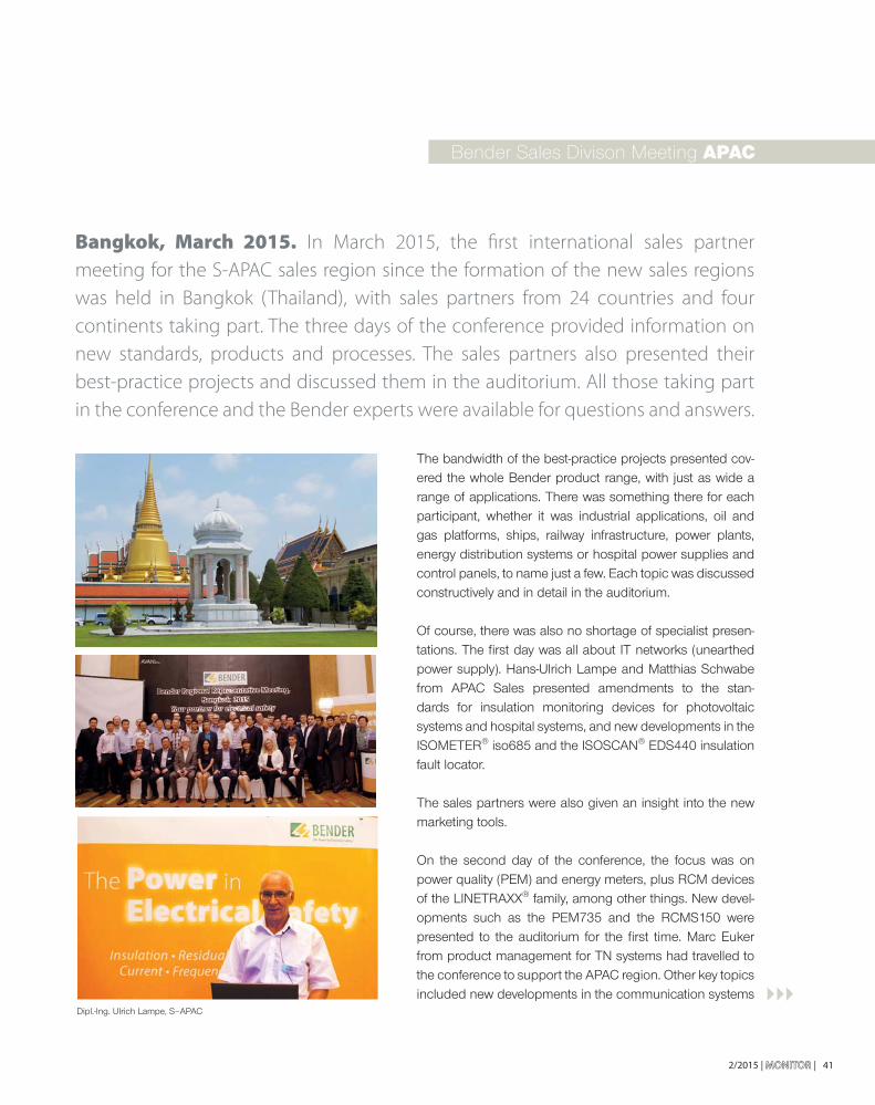
2/2015 | MONITORMONITOR | 41
Bangkok, March 2015. In March 2015, the fi rst international sales partner
meeting for the S-APAC sales region since the formation of the new sales regions
was held in Bangkok (Thailand), with sales partners from 24 countries and four
continents taking part. The three days of the conference provided information on
new standards, products and processes. The sales partners also presented their
best-practice projects and discussed them in the auditorium. All those taking part
in the conference and the Bender experts were available for questions and answers.
Bender Sales Divison Meeting APAC
The bandwidth of the best-practice projects presented cov-ered the whole Bender product range, with just as wide a range of applications. There was something there for each participant, whether it was industrial applications, oil and gas platforms, ships, railway infrastructure, power plants, energy distribution systems or hospital power supplies and control panels, to name just a few. Each topic was discussed constructively and in detail in the auditorium.
Of course, there was also no shortage of specialist presen-tations. The fi rst day was all about IT networks (unearthed power supply). Hans-Ulrich Lampe and Matthias Schwabe from APAC Sales presented amendments to the stan-dards for insulation monitoring devices for photovoltaic systems and hospital systems, and new developments in the ISOMETER® iso685 and the ISOSCAN® EDS440 insulation fault locator.
The sales partners were also given an insight into the new marketing tools.
On the second day of the conference, the focus was on power quality (PEM) and energy meters, plus RCM devices of the LINETRAXX® family, among other things. New devel-opments such as the PEM735 and the RCMS150 were presented to the auditorium for the fi rst time. Marc Euker from product management for TN systems had travelled to the conference to support the APAC region. Other key topics included new developments in the communication systems
Dipl.-Ing. Ulrich Lampe, S–APAC

| MONITORMONITOR | 2/201542
sector, such as the Condition Monitor Release 2 (CP700 Rel 2) and the new Gateway series (COM465=DP/IP) presented by Mario Zerbe. Ulrich Lampe also covered subjects relating to technical services and guarantees.
There was also plenty of culture from the host country. During a river cruise on the Chao Phraya, the delegates were not only able to enjoy a lovely evening meal, but also saw the Grand Palace and important temple com-plexes in Bangkok.
The third and last day focused on hospitals with a pre-sentation by Matthias Schwabe, followed by a discus-sion. There was also practical training on installation, commissioning and visualisation, which was provided by Mario Zerbe.
The presentations on the third day marked the end to the 2015 Regional Representative Meeting in Bangkok.
Feedback after the conference was very positive:
B E N D E R I N H O U S E
Dipl.-Wirt.-Ing. (FH) Mario Zerbe
S-APAC
“ The experience was memorable,
and the conference was very successful.”
Luu Thuy Nhu, Dat Hung Vietnam Sven Holla, Elteco Norway F.l.t.r.: P.K. Bhattacharyya, Bender India, S. Castellari, RDI Brasilia, R. Bender, RDI
Brasilia
Sergio Castellari, RDI Brasilia

2/2015 | MONITORMONITOR | 43
The aim of the joint meeting of Bender represen-tatives was to exchange information, reinforce and update product knowledge, application and standard knowledge and expand international net-working for the benefi t of Bender customers.
After the successful APAC (Asia-Pacifi c) meeting in spring, our representatives from 24 EMEA countries met up for three days in Oberursel. Delegates had come from as far afi eld as the Ivory Coast and South Africa. After starting off with some general informa-tion from Bender headquarters, there was an intense exchange with the product managers from Gruenberg. The delegates took part in a kind of circuit training, almost like speed-dating in small groups with the developers and product managers to discuss current developments and open questions on the respective product. Developers and product managers intro-duced their new products and applications at ten stands. The aim was to convince their audience of
the product in 20 minutes and explain the customer benefi ts. The emphasis was on the new products, such as the PEM735 network analyser, the 6-chan-nel AC/DC sensitive residual current monitoring device RCMS150 and the fi rst product based on the platform strate-gy, the ISOMETER® iso685 insulation monitoring device. The production strat-egy for hospital dis-tribution cabinets, which is a confi gu-rable standard pro-duct to simplify plan-
Bender Sales Division Meeting EMEA (Europa, Middle East, Africa) 2015
B E N D E R I N H O U S E
Successful kick-off event for the first international meeting of the EMEA sales division

| MONITORMONITOR | 2/201544
B E N D E R I N H O U S E
ning, promises improved delivery availability (available as of June 2016). The feedback was suitably optimistic. Some described the advances in technology as the greatest they had seen for many years. The information presented was rated as very good. At the end of the fi rst day, all the participants were exhausted but expressed a unanimous view that this kind of intensive technical exchange should be sched-uled into the next meeting again, with more time given to speed-dating.
The second day of the conference began with practi-cal training on mobile measuring PEM cases in small groups. This measuring case allows sales representa-tives all over the word to explain product characteristics and advantages, and demonstrate them in the fi eld.
This was followed by presentations on the Critical Infrastructure market segment, focussing on data cen-tres in particular. The most important challenges in a data centre include improving protection against elec-tric shock, increasing availability and increasing energy effi ciency. Bender has the products and software to make a contribution to improved solutions for these challenges. Our mission is to support data centre oper-ators in the intelligent use of resources.
The new platform solution mybender.com – present-ed by Marketing Manager Frank Baier – was very well received. This portal, with its powerful search engine, means that all representatives are just a mouse click away from all the product information, brochures, certifi cates and much more.
There was heated discussion about the latest news from the standardisation work, which was presented by Holger Potdevin, Manager of Standardisation. Each country has its own focus and different inter-pretation. The international discussion shows just how exciting the subject of standards can be. One thing is clear: the Bender Group and its represen-
Peter Eckert, S-EMEA

2/2015 | MONITORMONITOR | 45
from Bender UK reported of a customer who needed to guarantee a measurement which was completely reliable under extremely diffi cult framework conditions, with no margin for error. Once again, the Bender pro-fessionals were able to help, using their products to offer a solution and help him with his diffi cult work.
From Iran, we heard how important our CP700 product is for major industry and large manufacturing compa-nies to ensure a reliable energy management system. One of the major benefi ts of the CP700 is the fact that it is easy to use, with no additional software required.
Our French colleagues reported how the country’s nuclear power stations had been made safer thanks to Bender products.
As so often, there is little time to discuss everything at these events. Although even the breaks were used productively, it was clear at the end of the event that there were plenty more things to discuss, and this will be done at the same meeting in two years time, if not before. The end benefi ciaries of these international exchanges between all our partners are our customers all over the world, to whom we will be able to provide a quicker, better and more solution-orientated service, now and in the future.
tatives are highly committed to playing a role in shaping standards all over the world and giving its customers the right advice.
Joachim Wagner, Division Manager for System and Communication Technology, presented a vision of how Bender products will be able to communicate with themselves and their surroundings on a digital level in future.
On the third and last day of the conference, the focus was on example applications from various countries. The subsidiaries from Great Britain, Spain and Benelux, among others, were able to report interesting news from their countries.
In Spain, Bender is intensively collaborating with the expansion of the national railway network, providing not only products but also know-how to support the process. Bender professionals in the Netherlands are faced with completely different problems. They need a Bender consultant who could be used on water and in the air. This was crucial, since the projects very often involve taking helicopters to an offshore oil platform in order to analyse the situation on site and produce a perfect-fi t offer. Steve Mason
Dipl.-Ing. Ralf Wanser
S-EMEA
Bender Sales Divison Meeting EMEA
" The new platform solution mybender.com – presented by Marketing Manager Frank Baier –
was very well received."
Dipl.-Ing. Holger Potdevin, S-N

| MONITORMONITOR | 2/201546
A G E N T S C O R N E R
Wonlee Solution was founded in December 2005 based on the accumu-
lated experiences in the fi eld of power and automatic control. The head offi ce is
located in Gaepo-dong, Seoul, Korea, with a total of 14 employees. In 2014, Wonlee
Solution opened a branch in Busan for the sectors of shipbuilding and off shore
plants. Wonlee Solution is specialized in off ering solutions for electrical safety,
energy saving and power quality improvement.
A company specialized in comprehensive solutions for electrical safety and power quality

2/2015 | MONITORMONITOR | 47
Wonlee Solution including all our employees is committed to provide our customers with the appropriate products and the necessary technical support.
Recent changes in recognition of further electrical safety are leading to a great demand of new tech-nology and high effi ciency of products.
Wonlee Solution keeps introducing excellent Bender products and solutions to the customers, through which sales of Bender products are grad-ually increasing.
Wonlee Solution is reinforcing sales capacity by establishing a new offi ce in Busan at the end of 2014, in order to use a geographic bene-fi t where many shipbuilding and marine engi-neering companies (Hyundai Heavy Industries, Daewoo Shipbuilding and Marine, Samsung Heavy Industries, STX, etc.) are concentrated, and there-fore support sales activities and technology in this sector.
We provide wide-range solutions, such as improvement of power supply system reliability, power quality monitoring devices and energy saving systems, power supply systems and power quality improvement equipment, diag-nosis, design, operation and maintenance of power supply systems. Wonlee Solution assists customers in building stable and safe power supply systems.
Cooperation for safe power supply
Since we recognized the outstanding quali-ties of Bender technologies and products, Wonlee Solution pushed towards cooperation with Bender, considering it very helpful for the electrical industry of Korea. Finally Wonlee Solution was selected as an agency of Bender in September 2006. Since then, we started introducing products in Korea for customers of various industrial fi elds, which we continuously provide with reliable products.
The employees of Sales and Marketing

| MONITORMONITOR | 2/201548
A G E N T S C O R N E R
Wonlee Solution translates all major Bender cata-logues into Korean to distribute and provide cus-tomers of each fi eld with completed catalogues.
Wonlee Solution is joining overseas projects by strengthening support for EPC companies in Korea.
Project and Success Story
Within the framework of the largest power plant construction project this year, we are providing four power plants with insulation monitoring and earth fault location equipment (EDS systems) for almost 3000 feeders.
Sales promotion
shipbuilding and marine engineering exhibition in the world, which is held in Busan every two years. The exhibition stand has the purpose to show excel-lent products as well as create new markets.
By annually participating in four to fi ve electrici-ty-related exhibitions, such as Seoul International Electric Fair, Wonlee Solution showed regular and potential new customers new products and tech-nology in addition to demonstrating our exper-tise. Furthermore, Wonlee Solution keeps doing sales activities for the purpose of raising company awareness, and holding workshops for the employ-ees of other companies that were selected by region, through demo set and a product trial. Also Wonlee Solution is actively publicizing products and the company through its own seminars and presentations, and at the special seminar which is being held in big cities, including Korea Electric Association and The Korean Institute of Illuminating and Electrical Installation Engineers.
Won-Hong, LeeCEO
KimBusan Offi ce TW
The Technology-Team

492/2015 | MONITORMONITOR |
There are many world-wide popular and big shipbuilding companies in Korea. When this company fi rst introduced Bender products and solutions in the Korean market, it was not very common to apply them to the shipbuilding area. However, through continuous technical studies and design refl ections, Wonlee Solution was able to convince customers like Daewoo Shipbuilding and Marine Engineering of implementing our products and systems.
Wonlee Solution began introducing Bender products to the world-leveled shipbuilding com-panies, and is now providing dozens of civil and military ships with EDS systems and insulation monitoring devices (IMD).
We supply insulation monitoring devices (IMD) to the ESS (Energy Storage System) project pro-cessed by KEPCO, and continuously work on innovating our business.
In addition, we have great success even in the general industrial fi eld, such as residual current monitoring system (RCMS) supply to Samsung semiconductor line.
While keeping long-term cooperation relationship with Bender, many projects have been going along in a wide range. Our success would not be possible without the high quality and reliability of Bender products. We would also like to thank all the staff of Bender for supporting us with rapid and high-quality technology and marketing.
Eungwoo Lee
Wonlee Solutions
"We supply insulation monitoring devices (IMD)
to the ESS(Energy Storage System) project processed by KEPCO, and
continuously work on innovating our business.”

C U S T O M E R P O R T R A I T
| MONITORMONITOR | 2/201550
Breaking new ground with the rehabilitation of the future
Since it was founded in 1988, the Klinik Bavaria in Bad Kissingen has stood for
constant development. With a capacity of over 340 beds, it is one of the lead-
ing rehabilitation clinics in North Bavaria. The clinic has specialist departments
for orthopaedics, neurology and occupational health, plus the AWARE CARE
intensive care unit for the treatments of patients requiring ventilation.
AWARE CARE
Focussing on the patient
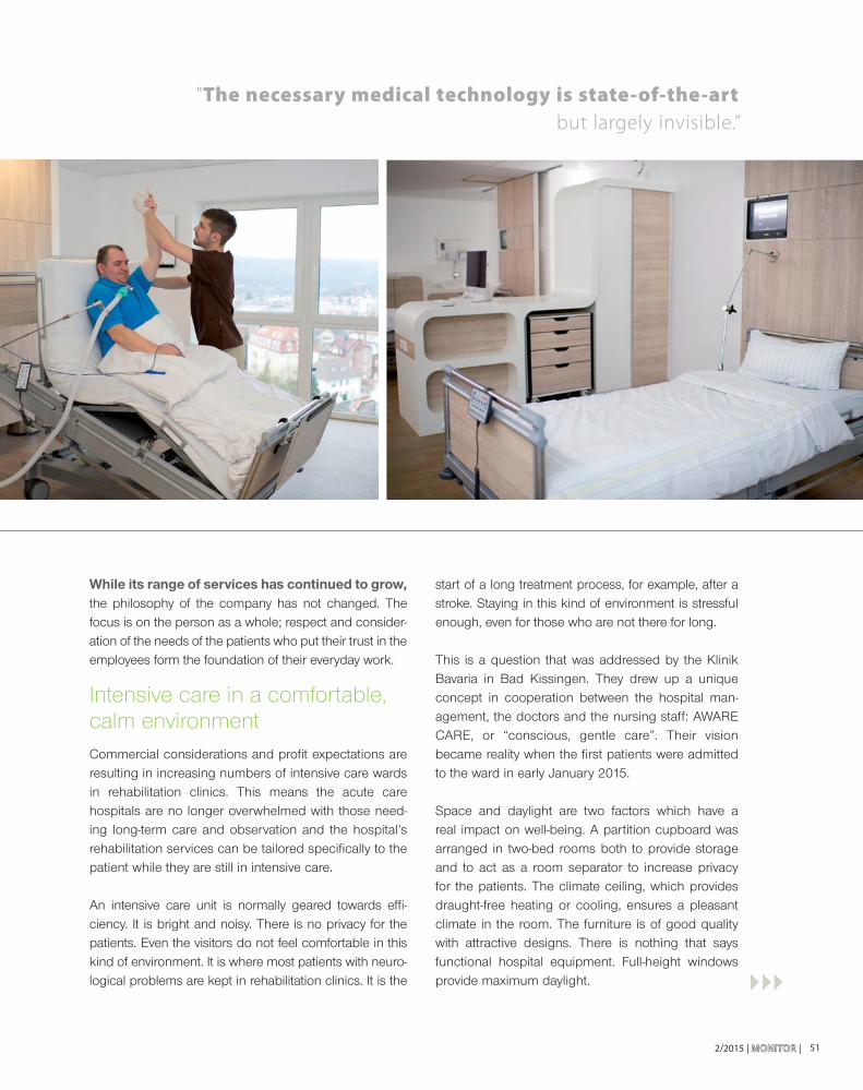
512/2015 | MONITORMONITOR |
start of a long treatment process, for example, after a stroke. Staying in this kind of environment is stressful enough, even for those who are not there for long.
This is a question that was addressed by the Klinik Bavaria in Bad Kissingen. They drew up a unique concept in cooperation between the hospital man-agement, the doctors and the nursing staff: AWARE CARE, or “conscious, gentle care”. Their vision became reality when the fi rst patients were admitted to the ward in early January 2015.
Space and daylight are two factors which have a real impact on well-being. A partition cupboard was arranged in two-bed rooms both to provide storage and to act as a room separator to increase privacy for the patients. The climate ceiling, which provides draught-free heating or cooling, ensures a pleasant climate in the room. The furniture is of good quality with attractive designs. There is nothing that says functional hospital equipment. Full-height windows provide maximum daylight.
"The necessary medical technology is state-of-the-art
but largely invisible.”
While its range of services has continued to grow, the philosophy of the company has not changed. The focus is on the person as a whole; respect and consider-ation of the needs of the patients who put their trust in the employees form the foundation of their everyday work.
Intensive care in a comfortable, calm environmentCommercial considerations and profi t expectations are resulting in increasing numbers of intensive care wards in rehabilitation clinics. This means the acute care hospitals are no longer overwhelmed with those need-ing long-term care and observation and the hospital’s rehabilitation services can be tailored specifi cally to the patient while they are still in intensive care.
An intensive care unit is normally geared towards effi -ciency. It is bright and noisy. There is no privacy for the patients. Even the visitors do not feel comfortable in this kind of environment. It is where most patients with neuro-logical problems are kept in rehabilitation clinics. It is the

| MONITORMONITOR | 2/201552
C U S T O M E R P O R T R A I T
Concealed technology
The necessary medical technology is state-of-the-art but largely invisible. The monitor is hidden by a blind and not only at night. The volume of alarm signals is reduced to an absolute minimum or report straight to a central unit. Medical technology should support the healing process, not disrupt it.
Sensory stimulation
Rehabilitation measures can begin as early as in the intensive care unit. Physiotherapy and positive stimula-tion of all kinds are necessary in order to allow patients with severe neurological conditions to return to a life which is as independent as possible. Therefore, sound, light and smells have also been considered. Projectors are used to beam images of landscapes, family photos or pictures of the patient’s own home onto the wall, while an audio system adds the sound to match and can also be used for music therapy
applications. The fragrance system provides pleasant aromas, which can stimulate or calm depending on the patient’s needs. Treatment is rounded off by feeling various materials and their textures. This specifi cally stimulates perception.
Patients also get stimulation from the landscaped, bar-rier-free roof terrace. Sun, wind, warmth, cold, … they can feel the outside world. Even healthy people often feel the need for fresh air. How would it feel if you had spent a long time in hospital?
Christian Lochner, Klinik Bavaria

532/2015 | MONITOR |
EXHIBITIONS 2015/16
Elecrama 13.02.2016 – 17.02.2016
Location: Bangalore, India
Medical Fair India 11.03.2016 – 13.03.2016
Location: Mumbai, India
Data Centre World 12.04.2016 – 13.04.2016
Location: London, Great Britain
Automation 22.08.2016 – 25.08.2016
Location: Mumbai, India
Healthcare Estates 4.10.2016 – 5.10.2016
Location: Manchester, Great Britain
Intersolar 19.10.2016 – 21.10.2016
Location: Mumbai, India
MATELEC 25.10.2016 – 28.10.2016
Location: Feria de Madrid
FISE 25.11.2016 – 27.11. 2016
Location: Medellin, Kolumbien
EXHIBITIONS NATIONAL
EXHIBITIONS INTERNATIONAL
SPS IPC Drives24.11.2015 – 26.11.2015
Location: Nuernberg
Fachschulung für Gebäudetechnik19.01.2016 – 21.01.2016
Location: Rostock
31. Symposium Photovoltaische Solarenergie 9.03.2016 – 11.03.2016
Location: Kloster Banz, Bad Staffeleisen
Light & Building13.03.2016 – 18.03.2016
Location: Frankfurt/Main
Hannover Messe25.04.2016 – 29.04.2016
Location: Hanover
Intersolar22.06.2016 – 24.06.2016
Location: Munich

| MONITORMONITOR | 2/201554
Dipl.-Ing. Harald SellnerHead of the Standards Department at Bender
I N T E R V I E W
Mr Sellner, you have been a member of the Bender team for more
than 40 years. How did you come to join the company?
I was looking for a trainee position after leaving school. A telephone
call to the company was followed by an invitation to an interview with
Walther Bender, and shortly afterwards my training agreement was in
the bag. Even today, I still like to recall Katrin and Walther Bender’s
very kind and warm-hearted natures. Not to mention D. Christian
Bender and his motto “There is only one proof of ability - action”,
which has considerably shaped the course of my career. My interests
in the engineering aspects of electrical safety are still very much alive
today. In this respect, my work in standards committees provides an
excellent forum for working out generally applicable solutions with
specialists from all over the world.
Are traditional family companies like Bender capable of meet-
ing the challenges of a globalised market?
Precisely because Bender is a family-owned and managed company
with a long tradition to look back on, we have the sort of organisa-
tional structure that can react very fl exibly, even to diffi cult situations.
Therefore we consider ourselves excellently equipped for the chal-
lenges of a globalised market.
We are always there whenever an opportunity arises where we could
contribute with our products to the electrical safety of people and
machines, anywhere in the world. Sometimes the way is really long
and diffi cult, but in most cases we succeed in gaining a market for our
ideas and products. Looking at the organisation as a whole, Bender
has a team of young, well-trained employees with innovative ideas
as well as many old-established staff members with a large pool of
experience and knowledge. This represents the ideal combination.
The subject of “standards” is usually greeted with some
scepticism because the suspicion of over-bureaucrati-
sation is never far away. What advantages does a stan-
dards system offer a manufacturer?
In international competition, standards form the basis for
worldwide trade without technical barriers. What standards
do not determine, each country’s lawmakers have to pass
regulations on. What this would mean, I’m sure I don’t have
to explain. In the technical world, many of the things we take
for granted nowadays function properly only against the
backdrop of a standard. When manufacturers take part in
the process of creating a standard, they have the advantage
of access to early information and can therefore prepare their
products to enter the market as quickly as possible. This
further motivates us to broaden our activities in this area and
network to a greater extent internationally. We can also ensure
our opinions are represented in the standardisation process.
What does active standardisation work involve?
The subject of “standards” might initially strike some people as
rather dry. But in reality it is quite the opposite. In the committee
working groups, we discuss the latest discoveries and trends,
which then eventually fi nd their way into a standard. The fi rst
phase is always to reach a consensus, i.e. you have to convince
other specialists of your opinion as well as agree with the opin-
ions of others. Contrary to what some might think, standards
committee meetings are not cosy chats over a cup of coffee,
but hard, concentrated work, always with the aim of creating
a standard that is clear and benefi cial to the user in practice.
PROFESSIONAL CAREER
1971 – 1974 Training as an electrician at Bender
1976 – 1980 Study Electrical Engineering with focus on automation, Technical College Gießen
1980 – 1981 Telefonbau & Normalzeit, Frankfurt
Ab 1981 Bender
1981 – 1986 Development engineer insulation monitoring mining industry/hospital
1986 – 1993 Sales manager Bender, medical technology testing systems for medical devices
1994 – 2000 Marketing
2001 – 2009 Division manager product management
2010 – 2011 Technical marketing department
2012 – 2014 The fi eld of standardisation
since 2015 Head of the Standards Department
Team standardisation

2/2015 | MONITORMONITOR | 55
Why does Bender have its own standards department?
The area of “standards” at Bender was progressed to great effect
for many years by Wolfgang Hofheinz and several other colleagues.
The demands of the actual work of standardisation have risen with
the increasing use of IT systems. Recent years have also seen the
formation of more committees in the areas in which we are interest-
ed. Bender is currently represented on about 60 standards com-
mittees. Since the beginning of the year, we have had two senior
offi cials, Holger Potdevin and me, on the committees, who also
coordinate standards activities with our other colleagues. Monika
Patterson is the secretary to one European technical committee
and gives us foreign language support. Vanessa Tröller organises
the administrative matters. One of our duties is to see that Bender
employees are always kept up to date with the latest happenings on
the standards scene. That is not only important for the development
of our products, but also for Sales, who in turn can keep our cus-
tomers well informed and advised.
What do users or customers get out of standards?
Many statistics show that the number of fatal electrical accidents,
e.g. from electric shock, is continuously decreasing. Standards
have made a considerable contribution to this. In the fi eld of elec-
trical safety in particular, users rely on having uniform standards of
safety, quality and functionality. Standard-compliant products are an
important prerequisite for unambiguous regulations in the fi eld of
product liability.
What is the main difference between a regulation and a
standard?
A regulation can be enacted only by a lawmaker. A standard is an
agreement under civil law and always refl ects a consensus of expert
opinion. Under certain circumstances, however, a standard may
take on a statutory character. In the event of legal confl ict, decisions
are based on the “state of the art” principle.
What organisations are involved in specifying national and
international standards?
Here we are speaking only about electrotechnical standards. Bodies
responsible for normative matters include DIN in Germany, CEN in
Europe and ISO for international standards. These organisations are
responsible for everything except electrotechnical standards. The
responsibility for drawing up electrotechnical standards in Germany
belongs to the German Commission for Electrical, Electronic &
Information Technologies (DKE) within DIN and VDE, in Europe
CENELEC (Comité Européen de Normalisation Électrotechnique)
and worldwide IEC (International Electrotechnical Commission).
As well as these bodies, there are further standards organisations,
such as NFPA and UL in the USA.
In which standards organisations is Bender represented?
Bender is represented at the DKE, IEC and CENELEC. We are
also active in working groups at DIN/DKE and in the USA with
NFPA and UL. Our specialist fi eld is the “prevention of electric
shock”. DKE K221 takes the lead on this issue in Germany. Then
there is UK964.1 for the IEC 61557 series of standards, which
encompasses the product standards for insulation monitoring
devices and is important to our work.
Our active participation in all these standards committees requires
not only sound knowledge of the subject but also diplomacy,
excellent communication skills and absolute familiarity with the
procedures. At Bender, I am proud to have worked in a team
that has such an outstanding reputation on standards commit-
tees. This is refl ected in Wolfgang Hofheinz, Karl-Hans Kaul and
Monika Patterson being recognised with the IEC-1906 Award.
Wolfgang Hofheinz was also DKE Chairman and was awarded
the DKE Golden Badge of Honour.
What are the current developments in the fi eld of stan-
dards? What technical trends are occupying the commit-
tees at the moment?
Technical systems are converging all the time, “Smart Grid”,
“renewable energy”, “electromobility” and “Power Quality” are
good examples of this trend, i.e. system concepts are increasingly
the focus of attention. But it is very apparent that not enough
young people are choosing to work in the standards fi eld. DKE
has already reacted to this with the “Next Generation” initiative.
And at Bender too, we are delighted about youngsters in our
company who are interested in standards.
How do you see the future for Bender in the coming years?
Bender has already made plans for the future. This applies not
just to the building alterations. With the new generation of devices
and practice-orientated products, which of course comply with
the relevant product standards, we are without doubt very well
equipped for the challenges ahead of us.
Mr Sellner, thank you for this most informative interview.
Timothy Hörl, Dreipass

The Bender Group with its main offi ce in Gruenberg/Hesse
has 70 representatives and 12 subsidiaries with nearly
700 employees worldwide.
You can fi nd your regional contacts at www.bender.de.
Bender GmbH & Co. KG
Londorfer Str. 65 • D-35305 Gruenberg / Germany
Fon: +49 6401 807-0 • Fax: +49 6401 807-259
E-Mail: [email protected] • www.bender.de