integral carriages sideshifter, fork positioner
TRANSCRIPT

Cascade is a Registered Trademark of Cascade Corporation
cascadecorporation
ERVICE MANUALSJ-Series
Integral Carriages − Sideshifter, Fork Positioner, Sideshifting Fork Positioner, Swing Frame & Slope Frame
Manual Number 6052504

ONTENTSC
i 6052504
PageINTRODUCTION, Section 1
Introduction 1Special Definitions 1
PERIODIC MAINTENANCE, Section 2100-Hour Maintenance 2500-Hour Maintenance 21000-Hour Maintenance 2Swing Frame and Slope Frame 3Hook-Type Fork Positioner Attachments 3
TROUBLESHOOTING, Section 3General Procedures 4
Truck System Requirements 4Tools Required 4Troubleshooting Chart 4
Plumbing 5Hosing Diagram – Sideshift and Fork Position 5Hydraulic Schematics 5
Fork Position Function 6Supply Circuit Test 6Fork Position Cicuit Test 6
Sideshift Function 7Supply Circuit Test 7Sideshift Circuit Test 7
Electrical Circuit 8SERVICE, Section 4
Sideshift/Fork Position Frame 9Removal and Installation 9Bearing Service 10
Mechanical Swing Wedge Bearing Service 11Valve 12
Fork Position Valve Removal 12Fork Position Valve Service 12
Sideshift Cylinder 13Removal and Installation 13Cylinder Disassembly 14Cylinder Inspection 14Cylinder Reassembly 15
Fork Positioner Cylinder 17Removal and Installation 17Cylinder Disassembly 18Cylinder Inspection 18Cylinder Reassembly 19Flow Restrictor Adjustment 20
Solenoid Valve 20Coil Service 20Valve Service 20
SPECIFICATIONS, Section 5Specifications 21
Hydraulics 21Auxiliary Valve Functions 21Torque Values 22

NTRODUCTIONI
6052504 1
1.2 Special DefinitionsThe statements shown appear throughout this Manual where special emphasis is required. Read all WARNINGS and CAUTIONS before proceeding with any work. Statements labeled IMPORTANT and NOTE are provided as additional information of special significance or to make your job easier.
WARNING - A statement preceded by WARNING is information that should be acted upon to prevent bodily injury. A WARNING is always inside a ruled box.
CAUTION - A statement preceded by CAUTION is information that should be acted upon to prevent machine damage.
IMPORTANT - A statement preceded by IMPORTANT is information that possesses special significance.
NOTE - A statement preceded by NOTE is information that is handy to know and may make your job easier.
1.1 IntroductionThis manual provides the Periodic Maintenance, Troubleshooting, Service and Specifications for Cascade J-Series Integral Fork Positioner/Sideshifter, Swing Frame and Slope Frame.
In any communication about the attachment, refer to the product I.D. number stamped on the nameplate as shown. If the nameplate is missing, the numbers can be found stamped on the top left surface of the attachment.
IMPORTANT: All hoses, tubes and fittings on these attachments are JIC.
NOTE: Specifications are shown in both US and (Metric) units.
MAXIMUM STRUCTURAL CAPACITYOF ATTACHMENT ONLY IS:CATALOG
NUMBER
SERIALNUMBER
ADDITIONALEQUIPMENT SYSTEM PRESSURE
PSI
BAR
INCHLOAD
CENTER
mmLOAD
CENTER
LBSAT
KgAT
REC
MAX
MAX
REC
cascade� corporation
WEIGHTKg
FOR TECHNICAL ASSISTANCE CONTACT:SERVICE: 1-800-227-2233 PORTLAND, OREGON USA
PARTS: 1-888-227-2233 SPRINGFIELD, OHIO USA667635R6
CAPACITY OF TRUCK AND ATTACHMENT COMBINATION MAY BE LESSTHAN ATTACHMENT CAPACITY SHOWN.CONSULT TRUCK NAMEPLATE.
WEIGHTLBS.
35E-PPS-A001
PTL 604920-1R0
35E-PPS-A001
PTL 604920-1R0
FP1194.eps
Nameplate
IMPORTANT: Information in this manual is based on a general attachment. Some functions are not shown. Contact Cascade for specific information.

6052504
ERIODIC MAINTENANCEP
2
2.1 100-Hour MaintenanceEvery time the lift truck is serviced or every 100 hours of truck operation, whichever comes first, complete the following maintenance procedures:
Check for loose or missing capscrews, worn or damaged hoses, and hydraulic leaks.
Check fork shafts for bends, damage or wear. Replace if bent. Consult Cascade if damaged or worn.
2.2 300-Hour MaintenanceAfter each 300 hours of truck operation, in addition to the 100-hour maintenance, perform the following procedures:
Tighten Cascade backrest (if equipped) capscrews to the following torque values:
M12 Capscrew – 75 ft.-lbs. (100 Nm)M16 Capscrew – 145 ft.-lbs. (195 Nm)
For other backrests, see OEM recommendations.
If equipped with zerk fittings – Apply general purpose chassis grease to upper and lower bearings.
Inspect frame retainers for wear. Replace if necessary. Tighten lower frame retainer capscrews to 165-200 ft.-lbs. (225-275 Nm).
Inspect fork shaft and front of lower frame bar for grease contamination. Remove contaminated grease from fork shaft and lower frame bar. Apply a general purpose chassis grease to the fork shaft. Apply a general purpose chassis grease or Slip-Plate (or a 'paint-on' graphite equivalent) to the lower frame bar.
2.3 1000-Hour MaintenanceAfter each 1000 hours of truck operation, in addition to the 100 and 300-hour maintenance, perform the following procedures:
Inspect sideshift upper and lower bearings for wear. If the frame is rubbing the carriage or lower bearing capscrews, replace the entire bearing set (see Service Manual for repair procedures).
Inspect forks for wear.
NOTE: Cascade fork safety kit 3014162 is available with wear calipers, inspection sheets and safety poster. Also available Cascade fork hook & carriage bar wear gauge 209560 (CL II), 209561 (CL III) and 6105257 (CL IV).
Inspect sideshift cylinder pivot pins and clevis pins for wear. Replace part as necessary.
Inspect fork position cylinder anchor nuts for wear. Replace if necessary.
NOTE: Anchors operate with a loose clearance.
Tighten lower bearing capscrews to 200 ft.-lbs. (270 Nm).
Tighten fork shaft retainers capscrews (if equipped) to 49 ft.-lbs. (66 Nm).
•
•
•
•
•
•
•
•
•
•
•
•
WARNING: After completing any service procedure, always test the Fork Positioner/Sideshifter through five complete cycles to make sure the attachment operates correctly before returning it to the job.
FP0736.eps
Shaft Retainer capscrews
Fork Shaft Upper Bearing
Sideshift Cyinder Clevis Pin Mounts
Lower Frame Bar Lower Bearing
Front View
Back (Driver's) View
FP1218.eps
Backrest Capscrews (if equipped)
Fork Positioner Cylinder Anchors Lower Frame
Retainer Capscrews

6052504
ERIODIC MAINTENANCEP
3
SS0817.eps
2.4 Swing and Slope AttachmentsIn addition to the previous page maintenance schedule, where applicable, the following maintenance procedures must be completed on swing and slope attachments:
300 Hours – Apply general purpose chassis grease to pivot pin zerk fittings and cam rollers.
1000 Hours – Inspect swing and slope frame pivot points for wear.
1000 Hours – Inspect wedge bearings (Mechanical swing frame) for wear.
1000 Hours – Inspect swing and slope cylinder pivot pins and clevis pins for wear. Replace part as necessary.
•
•
•
•
Cylinder Pivot Pins
Frame Pivot Pins
Cam RollersWedge Bearings
FP1212.eps
Upper Fork Carrier Bearings
Lower Fork Carrier Bearings
FP Cylinder Lug Capscrews
Fork Carrier Capscrews
Fork Pad Capscrews
2.5 Hook-Type Fork Positioner AttachmentsIn addition to the previous page maintenance schedule, where applicable, the following maintenance procedures must be completed on hook-type fork positioner attachments:
300 Hours – Apply general purpose chassis grease to fork carrier bearings.
300 Hours – Tighten capscrews as follows:
FP Cylinder Lug – 13-15 ft.-lbs. (18-20 Nm)Fork Pad – 500 ft.-lbs. (678 Nm)Fork Carrier – 28 ft.-lbs. (38 Nm)
NOTE: Apply Loctite 242 to FP Cylinder Lug and Fork Pad capscrews.
300 Hours – Apply general purpose chassis grease or Slip-Plate (or a 'paint-on" graphite equivalent) to the fork slider bars.
•
•
•
Fork Slider Bars
ROUBLESHOOTING
6052504
T
4
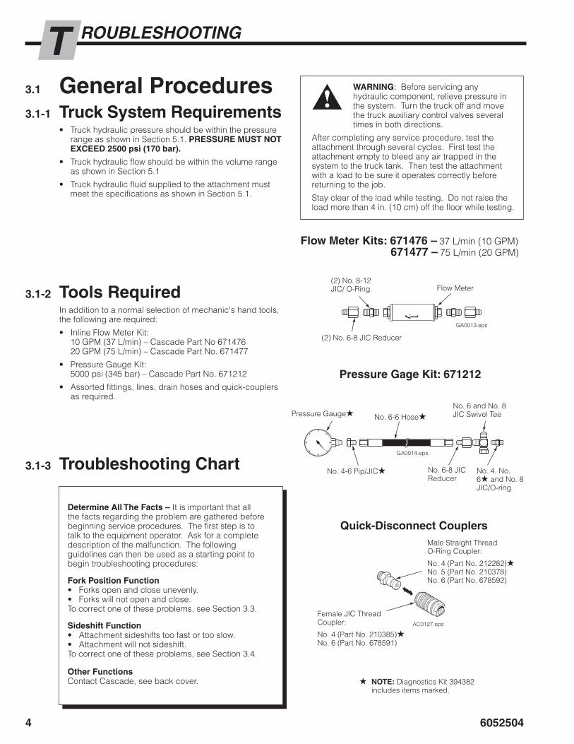
3.1 GeneralProcedures3.1-1 TruckSystemRequirements
Truck hydraulic pressure should be within the pressure range as shown in Section 5.1. PRESSUREMUSTNOTEXCEED2500psi(170bar).
Truck hydraulic flow should be within the volume range as shown in Section 5.1
Truck hydraulic fluid supplied to the attachment must meet the specifications as shown in Section 5.1.
•
•
•
3.1-2 ToolsRequiredIn addition to a normal selection of mechanic's hand tools, the following are required:
Inline Flow Meter Kit:10 GPM (37 L/min) – Cascade Part No 67147620 GPM (75 L/min) – Cascade Part No. 671477
Pressure Gauge Kit:5000 psi (345 bar) – Cascade Part No. 671212
Assorted fittings, lines, drain hoses and quick-couplers as required.
•
•
•
3.1-3 TroubleshootingChart
WARNING: Before servicing any hydraulic component, relieve pressure in the system. Turn the truck off and move the truck auxiliary control valves several times in both directions.
After completing any service procedure, test the attachment through several cycles. First test the attachment empty to bleed any air trapped in the system to the truck tank. Then test the attachment with a load to be sure it operates correctly before returning to the job.
Stay clear of the load while testing. Do not raise the load more than 4 in. (10 cm) off the floor while testing.
DetermineAllTheFacts– It is important that all the facts regarding the problem are gathered before beginning service procedures. The first step is to talk to the equipment operator. Ask for a complete description of the malfunction. The following guidelines can then be used as a starting point to begin troubleshooting procedures:
ForkPositionFunction• Forks open and close unevenly.• Forks will not open and close.To correct one of these problems, see Section 3.3.
SideshiftFunction• Attachment sideshifts too fast or too slow.• Attachment will not sideshift.To correct one of these problems, see Section 3.4.
OtherFunctionsContact Cascade, see back cover.
GA0013.eps
GA0014.eps
AC0127.eps
FlowMeterKits:671476– 37 L/min (10 GPM)671477– 75 L/min (20 GPM)
(2) No. 8-12 JIC/ O-Ring
(2) No. 6-8 JIC Reducer
Flow Meter
PressureGageKit:671212
Pressure Gauge★ No. 6-6 Hose★No. 6 and No. 8 JIC Swivel Tee
No. 4. No. 6★ and No. 8 JIC/O-ring
No. 6-8 JIC Reducer
No. 4-6 Pip/JIC★
Quick-DisconnectCouplersMale Straight Thread O-Ring Coupler:
No. 4 (Part No. 212282)★No. 5 (Part No. 210378)No. 6 (Part No. 678592)
Female JIC Thread Coupler:
No. 4 (Part No. 210385)★No. 6 (Part No. 678591)
★ NOTE: Diagnostics Kit 394382 includes items marked.
6052504
ROUBLESHOOTINGT
5
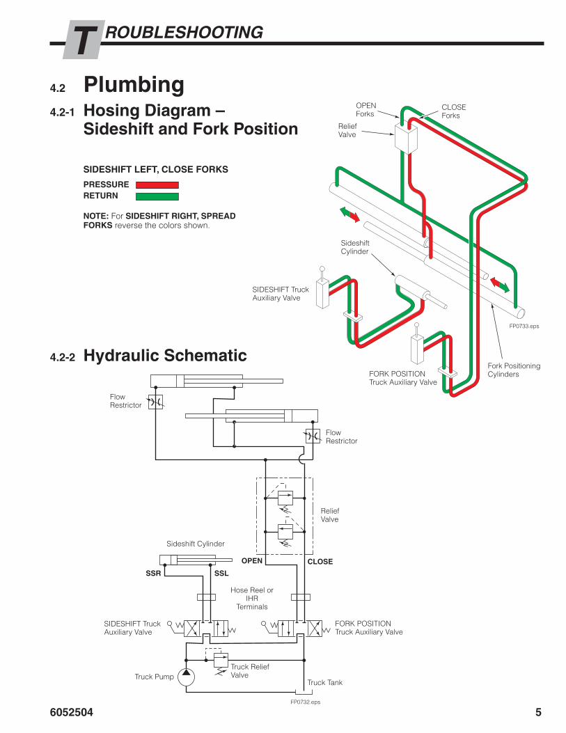
4.2 Plumbing4.2-1 HosingDiagram–
SideshiftandForkPosition
FP0733.eps
CLOSE Forks
OPEN Forks
Relief Valve
Fork Positioning Cylinders
Sideshift Cylinder
SIDESHIFTLEFT,CLOSEFORKS
PRESSURERETURN
NOTE: For SIDESHIFTRIGHT,SPREADFORKS reverse the colors shown.
SIDESHIFT Truck Auxiliary Valve
FORK POSITION Truck Auxiliary Valve
4.2-2 HydraulicSchematic
FP0732.eps
Flow Restrictor
Flow Restrictor
Relief Valve
Sideshift Cylinder
Hose Reel orIHR
Terminals
SIDESHIFT Truck Auxiliary Valve
FORK POSITION Truck Auxiliary Valve
Truck PumpTruck Relief Valve
Truck Tank
SSR SSL
OPEN CLOSE

ROUBLESHOOTING
6052504
T
6
3.3 ForkPositionFunctionThere are five potential problems that could affect the fork positioning function:
Forks and fork carriers binding on bearings
Incorrect hydraulic pressure or flow.
External leaks.
Loose electrical connection or defective solenoid coil or valve (if equipped).
Worn/defective cartridge valves or cylinder seals.
3.3-1 SupplyCircuitTest1 Check the truck pressure at the carriage hose terminal.
Pressure must be within 100 psi (7 bar) of that specified in the truck service manual. PRESSUREMUSTNOTEXCEED2500psi(170bar)totheforkpositioner/sideshifter. See Section 5.1 for recommended operating pressure.
2 Check the flow volume at the carriage hose terminal. See Section 5.1 for recommended flow volume.
3 Fully spread forks. Hold the lever in the OPEN position for 2 seconds. Release the lever. Check for external leaks at fittings, hoses and valve.
3.3-2 ForkPositionCircuitTest1 If equipped, press the solenoid button. Listen for a
'click' at solenoid valve. If no sound is heard, check the fuse, wiring and coil. See Section 3.5.
IMPORTANT: Solenoid operated valves must be plumbed so that the solenoid is energized during the fork positioning function.
2 Fully open and close forks. If the forks move at different speeds, adjust the flow restrictors for equal fork speed. See Section 4.5-5.
3 Turn the truck off. Connect a 5000 psi (345 bar) pressure gauge to the OPEN line below the valve.
4 Start the truck. Fully spread forks. Hold the lever in the OPEN position for a few seconds.
5 Release the lever. Watch the pressure gauge:
If the pressure drop isless than 150 psi (10 bar) initially and additional drop does not exceed 25 psi (2 bar) per minute, the problem is not hydraulic. See Section 3.3, above.
If the pressure drop ismore than 150 psi (10 bar) initially, one of the relief valve's cartridges is faulty. Replace both cartridges.
6 Fully close forks. Hold the lever in OPEN position for a few seconds. If the pressure still drops more than 150 psi (10 bar), the cylinders are faulty and should be serviced. See Section 4.5.
•
•
•
•
•
•
•
WARNING: Before removing hydraulic lines or components, relieve pressure in the hydraulic system. Turn truck off and open the truck auxiliary control valve(s) several times in both directions.
FP1195.eps
FP1196.eps
2
3
24
Flow Meter
Flow Restrictor
Pressure Gauge
Back(Driver's)View
FrontView

6052504
ROUBLESHOOTINGT
7
3.4 SideshiftFunctionThere are five potential problems that could affect the sideshifting function:
Binding due to bending damage, wear, lack of lubrication. See Periodic Maintenance, Section 2.
Incorrect hydraulic pressure or flow to sideshift cylinder.
External leaks.
Lower mounting hooks installed incorrectly. Refer to User Manual 6082563 Installation Section.
Worn or defective cylinder seals.
3.4-1 SupplyCircuitTest1 Check the pressure supplied by the truck at the carriage
hose terminal. Pressure must be within the range shown in Specifications, Section 5.1. PRESSURETOTHEFORKPOSITIONER/SIDESHIFTERMUSTNOTEXCEED2500psi(170bar).
2 Check the flow volume at the carriage hose terminal. Flow must be within the range shown in Specifications, Section 5.1
3 Fully sideshift left and right, holding the lever in each SIDESHIFT position for a few seconds. Release the lever and check for external leaks at fittings, hoses, valve and cylinders.
3.4-2 SideshiftCircuitTest1 If equipped, press the solenoid button. Listen for a
'click' at the solenoid valve. If no sound is heard, check the fuse, wiring and coil. See Section 3.5.
IMPORTANT: Solenoid operated valves must be plumed so that the solenoid is notenergized during the sideshifting function.
2 Turn the truck off. Relieve system pressure. Disconnect the sideshift base end supply hose from the internal reeving or hose terminal fitting. Cap the supply fitting and place the hose end in a drain.
3 Start the truck and actuate the SIDESHIFT LEFT lever for 5 seconds:
If there is substantialhydraulicflow out of the drain hose, the sideshift cylinder is faulty and requires service.
If there is nohydraulicflow out of the hose, the problem is not hydraulic. See Section 3.4, above.
•
•
•
•
•
•
•
WARNING: Before removing hydraulic lines or components, relieve pressure in the hydraulic system. Turn truck off and open the truck auxiliary control valve(s) several times in both directions.
FP1197.eps
3
2Sideshift base end hose
Back(Driver's)View

ROUBLESHOOTING
6052504
T
�
3.5 ElectricalCircuit(SolenoidEquippedAttachments)Use the electrical schematic and diagram shown and follow the steps below:
1 Check the control knob circuit fuse. Replace if necessary.
2 Check for loose electrical connections at the truck ignition switch, control knob button, solenoid coil terminal and diode.
3 Remove the diode from the solenoid coil terminal. Test with an ohmmeter for high resistance in one direction and no resistance in the other direction. If there is no resistance in both directions, replace the diode.
NOTE: When replacing the diode, the banded (+) end must connect to the positive (+) side of the coil and wiring as shown.
4 Disconnect the electrical leads from the solenoid coil terminals. Use a voltmeter to determine if voltage is present at the electrical leads when the button is pressed.
If there is nocurrent to the solenoid, troubleshoot the electrical circuit for shorts.
If there is current to the solenoid, test for coil continuity.
5 Test the coil continuity by placing an ohmmeter test lead on each solenoid coil terminal (ohmmeter on Rx1 scale).
If there is an ohmmeter reading, the coil is good.
If the coil is good, but the solenoid does not 'click' when the control knob button is pressed, the solenoid cartridge may be jammed.
If there is no ohmmeter reading, the coil is defective. Replace coil.
•
•
•
•
•
CL0258.eps
CL0257.eps
7.5 amp Fuse White Black
Knob Button (Normally Open)
DiodeSolenoid Coil
Diode
7.5 amp Fuse
BlackWhite
Solenoid CoilUser supplied wire

6052504
ERVICES
�
4.1 Sideshift/ForkPositionFrame
4.1-1 RemovalandReplacementNOTE: The Sideshift/Fork Position frame, with forks in place, may be removed from the integral carriage bars to service the sideshifter bearings.
6 For installation, reverse the above procedures with the following exceptions:
Clean and inspect carriage bars for damage and smoothness. Bars should be parallel and ends should be flush.
Clean all bearing areas of built-up dirt and grease.
Inspect bearings for wear and replace if necessary (see Section 5.1-2).
•
•
•
WARNING: Before disconnecting hoses, relieve pressure in the attachment hydraulic system. Turn the truck off and move the truck auxiliary valve control lever several times in both directions.
1 Disconnect the supply hoses to the fork positioner valve and sideshift cylinder. Cap hoses and tag for reassembly.
2 Remove the clevis pins and remove the sideshift cylinder from the frame.
3 Backrest may be removed or left in place to assist in lifting frame from carriage. For Cascade backrests reassembly, tighten backrest capscrews to 145 ft.-lbs. (195 Nm).
4 Remove the lower retainers. For reassembly, tighten capscrews to 120 ft.-lbs. (165 Nm).
5 Attach an overhead hoist and slings to the frame. Lift away from the truck carriage.
NOTE: Bearings may remain on the carriage bars.
WARNING: Check the attachment weight (located on the nameplate) to make sure the overhead hoist is at least the rated capacity of the attachment.
FP1198.eps
4
2
FP1199.eps
5
Upper Bearings
Lower Bearings

6052504
ERVICES
10
4.1-2 BearingService1 Remove the Sideshift/Fork Position frame from the truck
carriage as described in Section 4.1-1.
2 Remove and inspect the upper bearings. If any bearing is worn to less than .4 in. (10 mm) thickness, replace all bearings.
IMPORTANT: Make sure upper bearings are properly positioned and seated on the upper integral carriage bar, as shown. Proper lower hook clearance requires that all bearings be properly positioned on the top carriage bar.
3 Remove and inspect the lower bearings. If any bearing is worn to less than .4 in (10 mm) thickness, replace all bearings.
4 For reassembly, reverse the above procedures with the following exceptions:
Use grease to hold the upper bearings in position on the carriage bar when replacing the frame.
Tighten lower bearing capscrews to 202 ft-lbs. (274 Nm).
•
•
FP1200.eps
2
3
4

6052504
ERVICES
11
FP1205.eps
4.2 MechanicalSwingWedgeBearingService
WARNING: Before disconnecting hoses, relieve pressure in the Attachment hydraulic system. Turn the truck off and move the truck auxiliary valve control lever several times in both directions.
1 Disconnect the supply hoses to the swing cylinder. Cap hoses and tag for reassembly.
2 Remove the clevis pin from the swing cylinder rod end.
3 Remove the clevis pins from the push rod assembly and remove the push rod assembly from the wedges.
4 Remove the retainers from the cam pins and remove the cam rollers from the frame.
5 Rotate the swing frame to one side. Slide out the opposite side wedge.
6 Replace the upper and lower wedge bearings.
7 Reinstall wedge and rotate the swing frame to the center.
8 For the opposite side, repeat steps 5 and 6.
� For reassembly reverse the steps 1-4 with the following exceptions:
If the swing frame slops or binds between the cam rollers and wedges, adjust the push rod assembly ends to extend or shorten.
•
4
5
6 8
5 2
3
Retainer
Cam Roller
Cam Pin
Push Rod Assembly
Wedge
Wedge Bearings

6052504
ERVICES
12
4.3 ValvesNOTE: Not all valves are covered. Contact Cascade to replace valve components.
4.3-1 ForkPositionValveRemovalWARNING: Before servicing any hydraulic component, relieve pressure in the system. Turn the truck off and move the truck auxiliary control valves several times in both directions.
1 Disconnect the hoses from the valve. Tag hoses for reassembly.
2 Disconnect the tubing at the bottom of the valve. Plug the tubing ends.
3 Remove the capscrews fastening the valve to the frame and remove the valve. For reassembly, tighten the capscrews to 15 ft.-lbs. (22 Nm).
4 For reassembly, reverse the above procedures with the following exceptions:
Service that valve as describe in Section 4.3-2.•
4.3-2 ForkPositionValveServiceIMPORTANT: Service the valve in a clean work area.
1 Remove the valve from the sideshift frame as described in Section 4.3-1.
2 Remove the crossover relief valve cartridges from the valve. Remove the O-rings and back-up rings from the cartridges.
3 Remove the fittings from the valve.
4 Clean all parts with solvent.
5 For reassembly, reverse the above procedures with the following exceptions:
Replace O-rings and back-up rings on relief valve cartridges as shown.
•FP0731.eps
2
3
Crossover Relief Valve Cartridge
Body
FP0730.eps
O-Rings
Back-Up Rings
5
FP1207.eps
Valve
CrossoverReliefCartridge

6052504
ERVICES
13
4.4 SideshiftCylinder4.4-1 RemovalandInstallation
NOTE: The following procedures can be performed with the Sideshift/Fork Position frame mounted on the truck.
1 Disconnect the hoses from the cylinder ports and tag for reassembly.
2 Remove the clevis pins from the cylinder ends and remove the cylinder from the sideshifting frame.
3 For reassembly, reverse the above procedures with the following exceptions:
Service the cylinder as described in Section 4.4-2.
Operate the sideshifter through several full cycles to clear the system of any entrapped air. Check fittings and hoses for leaks.
•
•
WARNING: Before disconnecting hoses, relieve pressure in the attachment hydraulic system. Turn the truck off and move the truck auxiliary valve control lever several times in both directions.
FP0773.eps
2
1SIdeshift Rod End
Sideshift Base End
Clevis Pins
6052504
ERVICES
14
SS0088.eps
6
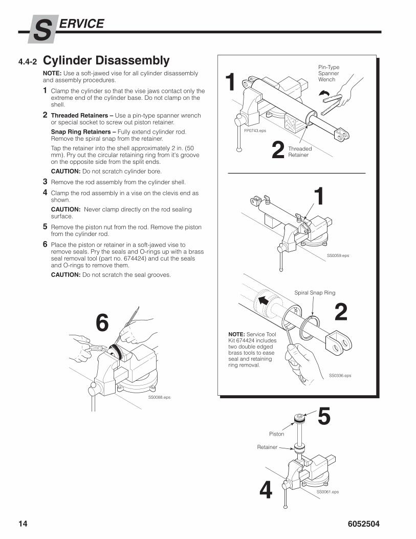
4.4-2 CylinderDisassemblyNOTE: Use a soft-jawed vise for all cylinder disassembly and assembly procedures.
1 Clamp the cylinder so that the vise jaws contact only the extreme end of the cylinder base. Do not clamp on the shell.
2 ThreadedRetainers– Use a pin-type spanner wrench or special socket to screw out piston retainer.
SnapRingRetainers– Fully extend cylinder rod. Remove the spiral snap from the retainer.
Tap the retainer into the shell approximately 2 in. (50 mm). Pry out the circular retaining ring from it's groove on the opposite side from the split ends.
CAUTION: Do not scratch cylinder bore.
3 Remove the rod assembly from the cylinder shell.
4 Clamp the rod assembly in a vise on the clevis end as shown.
CAUTION: Never clamp directly on the rod sealing surface.
5 Remove the piston nut from the rod. Remove the piston from the cylinder rod.
6 Place the piston or retainer in a soft-jawed vise to remove seals. Pry the seals and O-rings up with a brass seal removal tool (part no. 674424) and cut the seals and O-rings to remove them.
CAUTION: Do not scratch the seal grooves.
FP0743.eps
SS0061.eps
1
2
5
4
Pin-Type Spanner Wench
Threaded Retainer
Piston
Retainer
SS0059.eps
SS0336.eps
1
Spiral Snap Ring
2NOTE: Service Tool Kit 674424 includes two double edged brass tools to ease seal and retaining ring removal.

6052504
ERVICES
15
4.4-3 CylinderInspectionInspect the rod, piston and retainer for nicks or burrs. Minor nicks or burrs may be removed with 400-grit emery cloth. If they cannot be removed, replace the parts.
Inspect the cylinder bore and remove any minor nicks or burrs with a butterfly. If they cannot be removed, replace the part.
NOTE: Minor nicks are those that will not pass hydraulic fluid under pressure.
Inspect the outside of the shell for any deformities or cuts that could impair performance or cause leaks under pressure. If necessary, replace the part.
•
•
•
FP0738.eps
Piston Nut Piston Shell Rod Retainer
NOTE: Snap Ring Retainer not shown

6052504
ERVICES
16
4.3-4 CylinderReassembly1 Polish the piston and retainer chamfer angles with
400-grit emery cloth to ease seal installation.
2 Note the direction of the pressure seals. Pressuresealsmustbeinstalledwiththeliptowardthehighpressuresideofthecylinder.
3 Lubricate new seals and O-rings with O-ring lube or petroleum jelly.
4 Install a new pressure seal and back-up ring (if equipped), wear ring (if equipped) on the piston. If equipped, install a new O-ring in the piston.
5 Install a new pressure seal, wiper, O-ring and back-up ring on the retainer, as shown.
6 Clamp the rod at the clevis end in a soft-jawed vise.
CAUTION: Do not clamp on the cylinder rod sealing surface.
7 ThreadedRetainers–Apply a thick film of petroleum jelly to the retainer ID. Install the retainer on the rod. Use a seal loader as required to prevent damage to the seals.
8 Install the piston on the rod. Tighten the nut as shown.
� Apply a thick film of petroleum jelly to the cylinder shell and piston OD. Install the rod assembly into the cylinder shell. Use a piston/seal loader as required to prevent damage to the seals.
10 ThreadedRetainers– Use a pin-type wrench to screw the retainer into the shell. Tighten the retainer as shown.
SnapRingRetainers– Tap retainer into shell far enough to install the circular retaining ring in its groove.
Fully extend rod. Install the spiral snap ring on the retainer.
SS0063.eps
SS0061.eps
SS0334.eps
1,4
8
�
6
7
Nut
Piston
Retainer
Piston/Seal Loader
Piston/Rod Assembly
FP0739.eps
Wear Ring
Back-up Ring
O-Ring
Piston U-cup Pressure SealNoteSealDirection
4 5 5Wiper
Back-up RingO-Ring
Pressure Seal
Torque Piston Nut 200-250 ft.-lbs. 271-339 Nm.
Torque Retainer 350-400 ft.-lbs. 475-542 Nm.
TYPE1

6052504
ERVICES
17
SS0822.eps
TYPE2
TYPE3
SS0823.eps
Piston U-cup Pressure SealNoteSealDirection Pressure Seal
O-Ring
Back-up Ring
Wiper
Wear Ring
Torque Piston Nut 100-120 ft.-lbs.271-339 Nm
Retaining Ring Spiral Snap Ring
45
5
Piston U-cup Pressure SealNoteSealDirection
Pressure Seal
O-Ring
Wiper
Wear Ring
Torque Piston Nut 100-120 ft.-lbs.271-339 Nm
Retaining Ring Spiral Snap Ring
45
5
O-Ring

6052504
ERVICES
18
5 Disconnect the hydraulic lines from the cylinder to be removed. Plug the lines and cap the cylinder ports. Tag lines for reassembly.
6 Disconnect the cylinder base end from the frame by removing the cotter pin, locking cap and spherical nut. Lift the cylinder away from the frame.
NOTE: Some cylinders have a cotter pin and clevis pin assembly.
7 For reassembly, reverse the above procedures with the following exceptions:
Service cylinder as described in Section 4.5-2.
Lubricate threads and spherical nuts with chassis grease.
Install hex beveled washer on cylinder rod end.
NOTE: Beveled side faces lug, as shown.
Tighten spherical nuts to 160 ft.-lbs. (220 Nm).
NOTE: Nut tightens against hex washer, providing a loose operating clearance. Lubricate anchor joints with chassis grease.
Install locking caps using new cotter pins, if equipped.
Secure cylinder base ends with dowel pin, if equipped.
•
•
•
•
•
•
4.5 ForkPositionCylinders4.5-1 RemovalandInstallation
1 If equipped, remove the backrest to provide access to the cylinder head end anchors. For cascade backrest reassembly, tighten backrest capscrews to:
M12Capscrew− 75 ft.-lbs. (100 Nm)M16Capscrew− 145 ft.-lbs. (195 Nm)
Refer to the truck service manual for truck manufacturer's backrest.
2 Position the forks to mid range. Disconnect the cylinder rod ends from the lugs by removing the cotter pin, locking cap and spherical nut.
3 Retract the cylinder rods until they disengage from the lugs.
4 Slide the forks to maximum frame width to provide room to remove the cylinders.
WARNING: After completing this service procedure, test the attachment through five complete cycles. First test empty, then test with a load to make sure the attachment operates correctly before returning it to the job.
WARNING: Before disconnecting hydraulic lines, relieve pressure in the attachment hydraulic system. Turn the truck off and move the auxiliary control levers several times in both directions.
FP1208.eps
4
51
Lug Cotter Pin
Spherical Nut, Locking Cap
Cylinder Rod End
Hex Washer (beveled side toward lug)
Cotter pin and clevis pin assembly shown

6052504
ERVICES
1�
4.5-2 CylinderDisassembly1 Clamp the cylinder in a soft-jawed vise at the extreme
base end. Do not clamp on the shell.
2 Unscrew and remove the retainer using a claw-type spanner wrench as shown. (Part No. 678598)
3 Remove the rod assembly from the cylinder.
4 Clamp the rod at the clevis end in a soft-jawed vise as shown.
CAUTION: Do not clamp on the cylinder rod sealing surface.
5 Remove the piston nut. Remove the piston from the cylinder rod.
6 Place the piston or retainer in a soft-jawed vise to remove the seals. Pry the seals or O-rings up with a brass seal removal tool (Part No. 674424) and cut the seals to remove them.
CAUTION: Do not scratch seal grooves.
4.5-3 CylinderInspectionInspect the rod, piston and retainer for nicks or burrs. Minor nicks or burrs may be removed with 400-grit emery cloth. If they cannot be removed, replace the parts.
Inspect the cylinder bore and remove any minor nicks or burrs with a butterfly. If they cannot be removed, replace the part.
Inspect the outside of the shell for any deformities or cuts that could impair performance or cause leaks under pressure. If necessary, replace the part.
Inspect the spherical nuts and hex washer for wear. Replace as necessary.
•
•
•
•
FP0529.eps
CL1073.eps
SS0062.eps
12
4
5
6
FP0741.eps
Piston Nut Piston Shell Rod Spacer Retainer
Hex Washer
Spherical Nut, Locking Cap
6052504
ERVICES
20 FP0742.eps
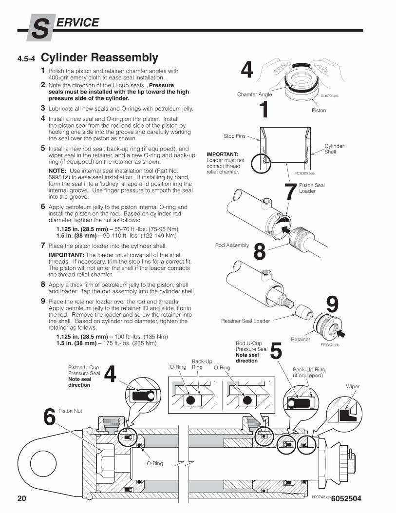
4.5-4 CylinderReassembly1 Polish the piston and retainer chamfer angles with
400-grit emery cloth to ease seal installation. 2 Note the direction of the U-cup seals. Pressure
sealsmustbeinstalledwiththeliptowardthehighpressuresideofthecylinder.
3 Lubricate all new seals and O-rings with petroleum jelly.
4 Install a new seal and O-ring on the piston. Install the piston seal from the rod end side of the piston by hooking one side into the groove and carefully working the seal over the piston as shown.
5 Install a new rod seal, back-up ring (if equipped), and wiper seal in the retainer, and a new O-ring and back-up ring (if equipped) on the retainer as shown.
NOTE: Use internal seal installation tool (Part No. 599512) to ease seal installation. If installing by hand, form the seal into a 'kidney' shape and position into the internal groove. Use finger pressure to smooth the seal into the groove.
6 Apply petroleum jelly to the piston internal O-ring and install the piston on the rod. Based on cylinder rod diameter, tighten the nut as follows:
1.125in.(28.5mm)– 55-70 ft.-lbs. (75-95 Nm)1.5in.(38mm)– 90-110 ft.-lbs. (122-149 Nm)
7 Place the piston loader into the cylinder shell.
IMPORTANT: The loader must cover all of the shell threads. If necessary, trim the stop fins for a correct fit. The piston will not enter the shell if the loader contacts the thread relief chamfer.
8Apply a thick film of petroleum jelly to the piston, shell and loader. Tap the rod assembly into the cylinder shell.
� Place the retainer loader over the rod end threads. Apply petroleum jelly to the retainer ID and slide it onto the rod. Remove the loader and screw the retainer into the shell. Based on cylinder rod diameter, tighten the retainer as follows:
1.125in.(28.5mm)– 100 ft.-lbs. (135 Nm)1.5in.(38mm)– 175 ft.-lbs. (235 Nm)
CL1070.eps
RC0320.eps
Piston
Chamfer Angle
4
1
FP0347.eps
7
8
�
54
6
Stop Fins
Cylinder Shell
Piston Seal Loader
IMPORTANT:Loader must not contact thread relief chamfer.
Retainer Seal Loader
Retainer
Rod Assembly
Piston Nut
Piston U-Cup Pressure Seal Notesealdirection
O-RingBack-Up Ring
Rod U-Cup Pressure SealNotesealdirection
Back-Up Ring (if equipped)
Wiper
O-Ring
O-Ring

6052504
ERVICES
21
FP1209.eps
4.5-5 FlowRestrictorAdjustmentNOTE: If forks have unequal movement, use the following steps to adjust the flow rate for the fork position cylinders.
1 Locate cylinder restrictor fittings. Loosen jam nuts and screw both flow restrictors in until they bottom. Screw each restrictor out (CCW) three turns.
2 Spread forks fully, then close. Look for unequal fork movement.
3 On faster fork (one that bottoms first), screw flow restrictor in (CW), 1/2 turn.
4 Repeat steps 2 and 3 until fork movement is equal. Tighten jam nuts.
Fork Positioning Cylinder
Flow Restrictor Adjustment Screw
Jam Nut
Restrictor Fitting13
4.6 SolenoidValve4.6-1 CoilService
1 Disconnect the wires and diode from the coil terminals.
2 Loosen the end cover capscrews. Remove the end cover and coil.
3 Install the new coil and end cover. Make sure that the terminals are positioned correctly.
4 For reassembly, reverse the above procedures except as follows:
Refer to the electrical schematic in Section 3.5 for correct wire and diode installation.
4.6-2 ValveServiceCheck the plunger in the valve body for free movement. If jammed or damaged, replace the solenoid valve as a complete assembly.
•
•
RC0204.eps
21
3
Coil
Solenoid Valve Assembly

6052504
PECIFICATIONSS
21
GA0082.eps
FP1166.eps
Sideshift Left
Hoist Up
Tilt Back
Tilt Forward
Sideshift Right
Hoist Down
Spread Forks– OR –
Swing Left– OR –
Slope CCW
Close Forks– OR –
Swing Right– OR –
Slope CW
Truck Relief Setting2300 psi (160 bar) Recommended2500 psi (170 bar) Maximum
Truck Flow Volume ➀Min. ➁ Recommended Max. ➂
J-Series 15 GPM(56 L/min.)
25 GPM(95 L/min.)
35 GPM(132 L/min.)
➀ Cascade J-Series Integral attachments are compatible with SAE 10W petroleum base hydraulic fluid meeting Mil. Spec. MIL-0-5606 or MIL-0-2104B. Use of synthetic or aqueous base hydraulic fluid is not recommended. If fire resistant hydraulic fluid is required, special seals must be used. Contact Cascade.
➁ Flow less than recommended will result in reduced system performance.
➂ Flow greater than maximum can result in excessive heating, reduced system performance and short hydraulic system life.
5.1 Specifications5.1-1 Hydraulics
5.1-2 Auxiliary Valve FunctionsCheck for compliance with ITA (ISO) standards:

6052504
PECIFICATIONSS
22
5.1-3 Torque ValuesFastener torque values for J-Series Integral Carriages are shown in the table below in both U.S. and (Metric) units. All torque values are also called out in each specific service procedure section throughout the manual.
Ref. Fastener Location Size Ft.-lbs. Nm
1 Valve Body Capscrew M8 15 22
2 Frame Retainer Capscrew M16 165-200 225-275
3 Fork Positioner Spherical Nut − 150-175 203-237
4 Shaft Retainer Capscrew M12 49 66
5 Backrest CapscrewM12 75 100
M16 145 195
6 Lower Frame Bearing Capscrew M10 200 270
FP1210.eps
FP1211.eps
1
23
4
5
6

Cascade Corporation 2008 04-2008 Part Number 6052504
c
Do you have questions you need answered right now? Call yournearest Cascade Service Department.Visit us online at www.cascorp.com
AMERICASCascade CorporationParts Sales2501 Sheridan Ave.Springfield, OH 45505Tel: 888-CASCADE (227-2233)Fax: 888-329-0234
Cascade Canada Inc.5570 Timberlea Blvd.Mississauga, OntarioCanada L4W-4M6Tel: 905-629-7777Fax: 905-629-7785
Cascade do BrasilRua João Guerra, 134Macuco, Santos - SPBrasil 11015-130Tel: 55-13-2105-8800Fax: 55-13-2105-8899
EUROPE-AFRICACascade Italia S.R.L.European HeadquartersVia Dell’Artigianato 137050 Vago di Lavagno (VR) ItalyTel: 39-045-8989111Fax: 39-045-8989160
Cascade (Africa) Pty. Ltd.PO Box 625, Isando 160060A Steel RoadSparton, Kempton ParkSouth AfricaTel: 27-11-975-9240Fax: 27-11-394-1147
ASIA-PACIFICCascade Japan Ltd.2-23, 2-Chome,Kukuchi NishimachiAmagasaki, Hyogo Japan, 661-0978Tel: 81-6-6420-9771Fax: 81-6-6420-9777
Cascade Korea121B 9L Namdong Ind. Complex, 691-8 Gojan-DongNamdong-KuInchon, KoreaTel: +82-32-821-2051Fax: +82-32-821-2055
Cascade-XiamenNo. 668 Yangguang Rd. Xinyang Industrial ZoneHaicang, Xiamen CityFujian ProvinceP.R. China 361026Tel: 86-592-651-2500Fax: 86-592-651-2571
Cascade India Material Handling Private LimitedNo 34, Global Trade Centre 1/1 Rambaugh ColonyLal Bahadur Shastri Road, Navi Peth, Pune 411 030(Maharashtra) IndiaPhone: +91 020 2432 5490Fax: +91 020 2433 0881
Cascade Australia Pty. Ltd.1445 Ipswich RoadRocklea, QLD 4107AustraliaTel: 1-800-227-223Fax: +61 7 3373-7333
Cascade New Zealand15 Ra Ora DriveEast Tamaki, AucklandNew ZealandTel: +64-9-273-9136Fax: +64-9-273-9137
Sunstream IndustriesPte. Ltd.18 Tuas South Street 5Singapore 637796Tel: +65-6795-7555Fax: +65-6863-1368