integrapac™ module and - dow chemical company engineered to reduce design and fabrication...
TRANSCRIPT

®Trademark of The Dow Chemical Company
(“Dow”) or an affiliated company of Dow
Dow Water & Process Solutions
IntegraPac™ Module and
Skid Product Manual
Version 1
May 2013
This manual is confidential. It is the property of Dow Water & Process Solutions. The contents may not be reproduced, transferred or released to any third party without the written permission of Dow Water & Process Solutions.

®Trademark of The Dow Chemical Company
(“Dow”) or an affiliated company of Dow
Table of Contents
1. Introduction ................................................................................................................................................ 1
2. Description of DOW™ IntegraPac™ Ultrafiltration Module ........................................................................ 2
2.1 IntegraPac™ Module and Skid Features ............................................................................................ 2
2.2 IntegraPac™ Module and Skid Specifications .................................................................................... 5
2.3 IntegraPac™ Module and Skid Installation ......................................................................................... 8
3. Shipping and Storage ................................................................................................................................. 9
4. DOW IntegraPac™ Ultrafiltration Process Description ............................................................................. 11
4.1 Process Operations .......................................................................................................................... 11
4.2 Pretreatment ..................................................................................................................................... 16
4.3 Cleaning ........................................................................................................................................... 17
Summary of Information ........................................................................................................... 17
4.4 Fouling .............................................................................................................................................. 17
5. Operating Information .............................................................................................................................. 18
5.1 Start Up ............................................................................................................................................ 18
Pre-start checks ....................................................................................................................... 18
Start Up .................................................................................................................................... 18
Module rinsing .......................................................................................................................... 19
5.2 Integrity Testing procedures ............................................................................................................. 19
Pressure hold/decay ................................................................................................................. 19
Visual inspection test ................................................................................................................ 19
5.3 Shut Down ........................................................................................................................................ 20
Manual shut down .................................................................................................................... 20
Equipment shut down during automatic operation ................................................................... 20
5.4 Operating and Cleaning Logs ........................................................................................................... 20
®Trademark of The Dow Chemical Company
(“Dow”) or an affiliated company of Dow
References
Figure 1: Material Size and Membrane Process Guide ....................................................................................... 1
Figure 2: Wall Cross Section of the Hollow Fiber ............................................................................................... 2
Figure 3: IntegraPacTM Module Photograph ...................................................................................................... 3
Figure 4: IntegraPac™ Skid Components ......................................................................................................... 4
Figure 5: Module Reference for Dimensions ...................................................................................................... 5
Figure 6: IntegraPac™ Skid Reference for Dimensions .............................................................................................. 7
Figure 7: Installation™ Drawing of Module ........................................................................................................ 8
Figure 8: Pallet of IntegraPac™ Modules for Shipping ........................................................................................ 9
Figure 9: Filtration Step for DOW UF Modules ................................................................................................. 12
Figure 10: Air Scour Step for DOW UF Modules .............................................................................................. 12
Figure 11: Air Scour Drain for DOW UF Modules ............................................................................................. 13
Figure 12: Top Backwash Step for DOW UF Modules ............................................................................................... 13
Figure 13: Bottom Backwash Step for DOW UF Modules ................................................................................. 14
Figure 14: Forward Flush Step for DOW UF Modules ....................................................................................... 14
Figure 15: Chemically Enhanced Backwash "Top" Step for DOW UF Modules ................................................... 15
Figure 16: Chemically Enhanced Backwash "Bottom" step for DOW UF Modules ............................................... 15
Figure 17: Clean in Place Cleaning Step for DOW UF Modules ................................................................................ 16
Figure 18: Pressure Hold Test Schematic ....................................................................................................... 20
Tables
Table 1: IntegraPacTM Module Connections ...................................................................................................... 5
Table 2: IntegraPac™ Module Dimensions and Specifications ........................................................................... 5
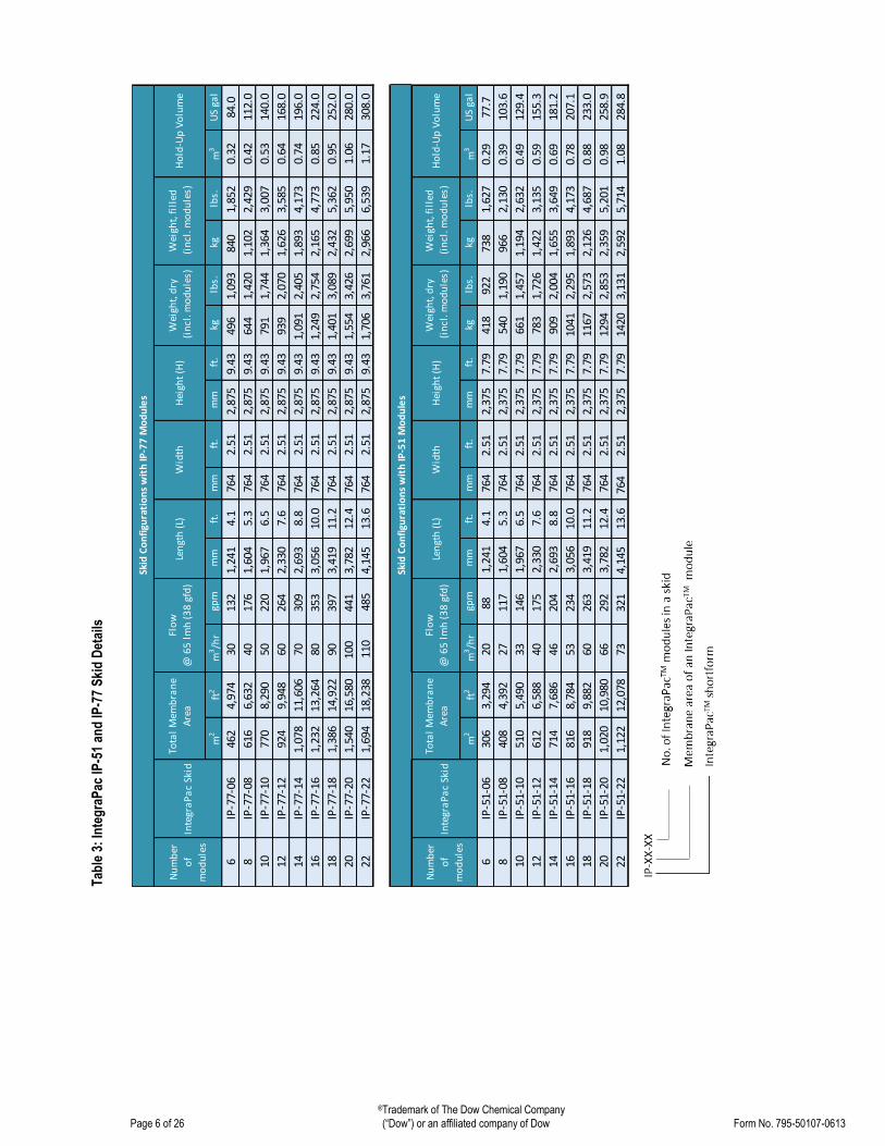
Table 3: IntegraPac™ IP-51 and IP-77 Skid Details ........................................................................................... 6
Table 4: Glycerin addition for Freezing Point Depression .................................................................................. 11
Table 5: DOW Ultrafiltration IntegraPac™ Modules and Skids Operating Conditions ........................................... 11
Table 6: Qualified Feed Water Quality Parameters .......................................................................................... 17
Table 7: Summary of Cleaning Processes ....................................................................................................... 17

®Trademark of The Dow Chemical Company
Page 1 of 26 (“Dow”) or an affiliated company of Dow Form No. 795-50107-0613
DOW™ IntegraPacTM Ultrafiltration Module and Skid Product Manual
1. Introduction
Ultrafiltration (UF) involves pressure-driven separation of materials from a feed solution. The technology achieves separation through sieving and is used to remove particulate and microbial contaminants, but does not remove ions or molecules of low molecular weight. The process typically operates with a feed pressure of 4 to 100 psig (0.28 to 6.9 bar). UF plants are automated and have low operational labor requirements. Depending on the feed water quality, these systems can require frequent cleaning. UF membranes generally may have a service life of five years or longer, depending on system operations. UF technology is commercially available in tubular, hollow-fiber, plate and frame, flat sheet, and spiral wound configurations.
UF membranes reject solutes ranging in size from 0.005 microns and larger. Figure 1 provides a guide to the relationship between common material sizes, separation processes, and pore size measurements. The UF membrane process separates molecules in solution on the basis of size. The pore size and molecular weight cut-off (MWCO) are often used to characterize a membrane. The pore size is the nominal diameter of the openings or micropores in the membrane expressed in micron (micron meters µm). The MWCO is the molecular mass or weight of a solute that rejects greater than 90 percent. The unit of measurement for MWCO is the Dalton (D).
Different membrane materials with the same nominal MWCO may have differing solute rejection. Pore size distribution and uniformity rather than the chemical nature of the membrane material may cause this effect. Because factors other than pore size or MWCO affect the performance of membranes, challenge studies are used to demonstrate membrane performance and benchmark different membranes.
Figure 1: Material Size and Membrane Process Guide
The DOW Ultrafiltration hollow fiber membrane shown in Figure 2 is 1.3 mm outside diameter and 0.7 mm inside diameter and is made from PVDF polymer. The fibers are strong because of a combination of the polymer type, the wall thickness, high porosity sub structure, and smaller pores at the surface of the fiber. The PVDF membranes offer high chemical resistance and are tolerant to temperatures ranging from 1 to 40ºC.

®Trademark of The Dow Chemical Company
Page 2 of 26 (“Dow”) or an affiliated company of Dow Form No. 795-50107-0613
The 0.03 μm nominal pore size combines high filtration performance and high flux. The smaller pore size provides stabile long term filtration performance compared to microfiltration hollow fiber membranes.
Dow has taken its Ultrafiltration technology to a new product format, referred to as IntegraPacTM modules and skids. This range includes interconnecting end caps that reduce skid capital costs and engineering design efforts.
2. Description of DOW™ Ultrafiltration IntegraPac™ Module
2.1 IntegraPacTM Module Features
The DOW Ultrafiltration IntegraPacTM modules are made from high strength, hollow fiber membranes and are
engineered to reduce design and fabrication requirements with features and benefits including:
0.03 µm pore size for removal of bacteria, viruses, and particulates, a 6 log removal of bacteria, a 2.5 log
removal on viruses and a <2.5 SDI guarantee with proper operation
PVDF fibers which offer strength, chemical and fouling resistance which allows for extended membrane
life and consistent long term performance Outside-In flow configuration which allows higher TSS feed waters, while maintaining reliable system
performance and producing high quality filtrate Innovative end-cap design enables direct coupling of modules reducing the need for piping and manifolds. The outside-in flow configuration allows the use of highly effective air scour cleaning which enhances particle removal and improves recovery. A dead-end flow format achieves higher recovery and energy savings. The module housing design eliminates the need for separate pressure vessels while the vertical orientation allows easy removal of air from cleaning and integrity testing processes.
Figure 2: Wall Cross Section of the Hollow Fiber
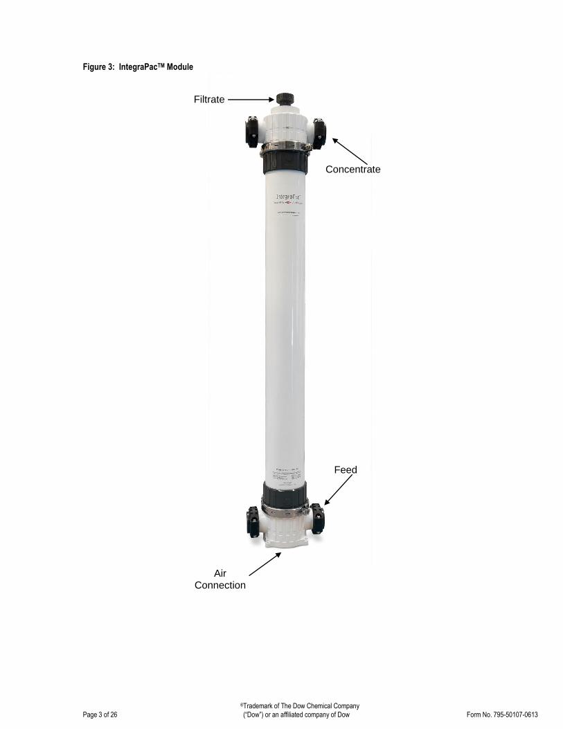
The IntegraPacTM module is shown in Figure 3. There are six connections on each module. The top end cap includes 4”DN 100 concentrate ports and an 1½” DN 40 union for the. The bottom end cap includes 4” DN 100 feed ports and a 3/8” air inlet connection on the side allowing for easy access. Included with the module are the couplers, air fitting, and transparent filtrate elbow. The IntegraPacTM skid offering is shown in Figure 4.
Selective Active Area
0.3 mm Wall Thickness
Feed Outside
to In Flow
Filtrate
Substructure
®Trademark of The Dow Chemical Company
Page 3 of 26 (“Dow”) or an affiliated company of Dow Form No. 795-50107-0613
Figure 3: IntegraPacTM Module
Filtrate
Feed
Concentrate
Air Connection

®Trademark of The Dow Chemical Company
Page 4 of 26 (“Dow”) or an affiliated company of Dow Form No. 795-50107-0613
Fig
ure
4:
Inte
gra
Pac
™ S
kid
Co
mp
on
ents

®Trademark of The Dow Chemical Company
Page 5 of 26 (“Dow”) or an affiliated company of Dow Form No. 795-50107-0613
Feed flow enters and is distributed into the modules through the side feed ports located on the bottom end cap. Feed flow enters the module on the outside of the fiber. The air connection is located on the side of the bottom end cap and is used for air scouring and integrity testing. The concentrate (discharge of waste flows from the outside of fiber) and filtrate ports (inside of fiber) are located on the top cap.
Table 1: IntegraPacTM Module and Skid Connections
IntegraPac Feed & Concentrate Filtrate Air Module DN 100 (4 inch) Coupler DN 40 (1.5 inch) Threaded Union 3/8 inch Threaded (G3/8”) Skid DN 100 (4 inch) Flange DN 150 (6 inch) Flange DN 65 (2.5inch) Flange
Table 1 shows the type and size of the connections for the IntegraPac™ modules.
2.2 INTEGRAPAC™ MODULE AND SKID SPECIFICATIONS
Table 2 shows dimensions and specifications for the IntegraPacTM modules as depicted in Figure 5. Table 3 includes the dimensions and specifications for the IntegraPacTM skids as depicted in Figure 6. Note that manufacturing and thermal expansion tolerances are not included in the dimensions below. Refer to the installation drawings for this information.
Table 2: IntegraPac™ Module Dimensions and Specifications
Figure 5: IntegraPac™ IP 51 and IP 77 Module Reference Drawing
Module Properties IntegraPac IP 51 IntegraPac IP 77
SI US SI US
Length - L 1988 mm 78.28" 2488 mm 97.95"
Length - L1 1500 mm 59.1" 2000 mm 78.7"
Length - L2 1689 mm 66.5" 2189 mm 86.2”
Length - L3 1864 mm 73.4" 2364 mm 91.3”
Diameter - D 225 mm 8.9" 225 mm 8.9"
Width – W1 360 mm 14.2" 360 mm 14.2"
Width – W2 342 mm 13.5" 342 mm 13.5"
Surface Area 51 m2 549 ft2 77 m2 829 ft2
Volume per Module 49 L 13 gal 53 L 14 gal
Weight (water filled) 102 kg 225 lbs 119 kg 262 lbs
Shipping Weight (w/o packaging) 53 kg 117 lbs 66 kg 146 lbs
Housing UPVC UPVC
®Trademark of The Dow Chemical Company
Page 6 of 26 (“Dow”) or an affiliated company of Dow Form No. 795-50107-0613
m2
ft2
m3/h
rgp
mm
mft
.m
mft
.m
mft
.kg
lbs.
kglb
s.m
3U
S ga
l
6IP
-77-
0646
24,
974
3013
21,
241
4.1
764
2.51
2,87
59.
4349
61,
093
840
1,85
20.
3284
.0
8IP
-77-
0861
66,
632
4017
61,
604
5.3
764
2.51
2,87
59.
4364
41,
420
1,10
22,
429
0.42
112.
0
10IP
-77-
1077
08,
290
5022
01,
967
6.5
764
2.51
2,87
59.
4379
11,
744
1,36
43,
007
0.53
140.
0
12IP
-77-
1292
49,
948
6026
42,
330
7.6
764
2.51
2,87
59.
4393
92,
070
1,62
63,
585
0.64
168.
0
14IP
-77-
141,
078
11,6
0670
309
2,69
38.
876
42.
512,
875
9.43
1,09
12,
405
1,89
34,
173
0.74
196.
0
16IP
-77-
161,
232
13,2
6480
353
3,05
610
.076
42.
512,
875
9.43
1,24
92,
754
2,16
54,
773
0.85
224.
0
18IP
-77-
181,
386
14,9
2290
397
3,41
911
.276
42.
512,
875
9.43
1,40
13,
089
2,43
25,
362
0.95
252.
0
20IP
-77-
201,
540
16,5
8010
044
13,
782
12.4
764
2.51
2,87
59.
431,
554
3,42
62,
699
5,95
01.
0628
0.0
22IP
-77-
221,
694
18,2
3811
048
54,
145
13.6
764
2.51
2,87
59.
431,
706
3,76
12,
966
6,53
91.
1730
8.0
m2
ft2
m3/h
rgp
mm
mft
.m
mft
.m
mft
.kg
lbs.
kglb
s.m
3U
S ga
l
6IP
-51-
0630
63,
294
2088
1,24
14.
176
42.
512,
375
7.79
418
922
738
1,62
70.
2977
.7
8IP
-51-
0840
84,
392
2711
71,
604
5.3
764
2.51
2,37
57.
7954
01,
190
966
2,13
00.
3910
3.6
10IP
-51-
1051
05,
490
3314
61,
967
6.5
764
2.51
2,37
57.
7966
11,
457
1,19
42,
632
0.49
129.
4
12IP
-51-
1261
26,
588
4017
52,
330
7.6
764
2.51
2,37
57.
7978
31,
726
1,42
23,
135
0.59
155.
3
14IP
-51-
1471
47,
686
4620
42,
693
8.8
764
2.51
2,37
57.
7990
92,
004
1,65
53,
649
0.69
181.
2
16IP
-51-
1681
68,
784
5323
43,
056
10.0
764
2.51
2,37
57.
7910
412,
295
1,89
34,
173
0.78
207.
1
18IP
-51-
1891
89,
882
6026
33,
419
11.2
764
2.51
2,37
57.
7911
672,
573
2,12
64,
687
0.88
233.
0
20IP
-51-
201,
020
10,9
8066
292
3,78
212
.476
42.
512,
375
7.79
1294
2,85
32,
359
5,20
10.
9825
8.9
22IP
-51-
221,
122
12,0
7873
321
4,14
513
.676
42.
512,
375
7.79
1420
3,13
12,
592
5,71
41.
0828
4.8
Hei
ght
(H)
Wei
ght,
dry
(in
cl. m
od
ule
s)
Wei
ght,
fil
led
(in
cl. m
od
ule
s)H
old
-Up
Vo
lum
e
Wei
ght,
fil
led
(in
cl. m
od
ule
s)H
old
-Up
Vo
lum
e
Skid
Co
nfi
gura
tio
ns
wit
h IP
-51
Mo
du
les
Nu
mb
er
of
mo
du
les
Inte
gra
Pa
c Sk
id
Tota
l M
emb
ran
e
Are
a
Flo
w
@ 6
5 l
mh
(3
8 g
fd)
Len
gth
(L)
Wid
th
Skid
Co
nfi
gura
tio
ns
wit
h IP
-77
Mo
du
les
Nu
mb
er
of
mo
du
les
Inte
gra
Pa
c Sk
id
Tota
l M
emb
ran
e
Are
a
Flo
w
@ 6
5 l
mh
(3
8 g
fd)
Len
gth
(L)
Wid
thH
eigh
t (H
)W
eigh
t, d
ry
(in
cl. m
od
ule
s)
Tab
le 3
: In
teg
raP
ac IP
-51
and
IP-7
7 S
kid
Det
ails

®Trademark of The Dow Chemical Company
Page 7 of 26 (“Dow”) or an affiliated company of Dow Form No. 795-50107-0613
Fig
ure
6:
Inte
gra
Pac
™ S
kid
Refe
ren
ce f
or
Dim
en
sio
ns
Exa
mpl
e: 2
x7
Inte
graP
ac IP
-51-
14 A
rran
gem
ent

®Trademark of The Dow Chemical Company
Page 8 of 26 (“Dow”) or an affiliated company of Dow Form No. 795-50107-0613
2.3 Installation Detailed installation instructions are provided for the Dow IntegraPacTM skids upon request.
Figure 7 provides the installation details for DOW™ IntegraPacTM modules.
Figure 7: Installation™ Drawing for IntegraPac™ IP 51 and IP 77 Modules

®Trademark of The Dow Chemical Company
Page 9 of 26 (“Dow”) or an affiliated company of Dow Form No. 795-50107-0613
3. Shipping and Storage
To control bacterial growth and prevent damage caused by fibers drying out, the DOWTM Ultrafiltration IntegraPacTM modules are wetted and stored in a non-hazardous standard storage solution containing pH buffered food-grade 1% wt. sodium metabisulfite (SMBS). At the end of the manufacturing process, storage solution is automatically injected into the modules and all inlet and outlet ports are sealed using plastic discs, couplings, and threaded plugs. If the modules will be exposed to low temperatures, glycerin can be added to the storage solution to prevent freezing. The modules are sealed in a plastic bag prior to boxing. Depending on the total number of modules and method of shipping, the modules are either shipped on pallets as shown in Figure 8 below or in crates. Skid components (underframe, air scour piping, filtrate piping) are shipped in a separate boxes or crates.
As part of the quality assurance program, all DOW™ IntegraPac™ modules are tested for integrity and performance (“wet tested”) at the factory, prior to packaging and shipment. Storage solution is automatically delivered into the module housings prior to sealing of the module ports. The target volume of storage solution used for each module is 4L (1 gal) for IP-51; and 6L (1.6 gal) for IP-77. After adding storage solution and sealing the openings, the modules are enclosed in plastic bags prior to boxing for dust protection. The storage solution volume and complete sealing of the module ports and openings help ensure a stable solution environment during transportation and storage of new modules. The bagged modules are stored in cardboard boxes, with one module per box. Saddle-shaped cushion inserts are located at both ends of the box and along the module to support and protect the modules from damage during shipping and handling. Depending on the total number of modules and required shipping method, the boxed modules are either palleted or crated for transportation. Other skid parts are placed in crates and shipped with the modules. Mechanical damage to module housing, membrane, and connections may result if the module, boxed module, pallet or crate is dropped, and otherwise mishandled. The modules should be handled with care, with particular attention during transportation.
Figure 8: Pallet of IntegraPac™ Modules for Shipping
Storage of New IntegraPac™ Modules:
Modules are recommended to be shipped and stored in their original packaging separate from the system racks, and loaded into the system just prior to start-up. There may be cases where the customer prefers to pre-install the modules on the system racks; for example, to allow factory acceptance testing of packaged or mobile systems prior to shipping, or work scheduling at site to eliminate the separate step for module loading.

®Trademark of The Dow Chemical Company
Page 10 of 26 (“Dow”) or an affiliated company of Dow Form No. 795-50107-0613
These guidelines should be followed for storage of new DOWTM IntegraPac™ modules:
Keep modules in original factory packaging.
To minimize the potential for leakage of storage solution, modules should be stored in horizontal position.
To prevent collapse of the boxed modules, limit vertical stacking to four layers of modules.
Store inside a cool and dry building or warehouse, away from sources of heat, ignition, and direct sunlight. An ambient temperature of 20°C (68 ºF) to 35°C (95 ºF) is recommended for ideal storage conditions.
Temperature limits for modules during shipping and storage is 1ºC (33.8 ºF) to 40ºC (104 ºF). Modules must be protected from freezing or excessive heat during shipping and storage. In order to avoid abrupt variations in temperature; equalization should be allowed to occur at a maximum temperature differential of +/- 1°C (1.8 ºF) per minute. If freezing conditions are anticipated during the customer’s shipping and storage of modules, please notify DW&PS at the time of order placement. Glycerine may be added to the storage solution at the factory prior to shipping to allow for shipment and storage at freezing conditions.
Sealed modules may be stored up to 1 year from date of manufacture, at the recommended storage conditions described above and in the original packaging.
Storage of modules installed on a skid:
Modules (hollow fibers) installed during assembly of a skid should not be allowed to dry out. Dry membrane fibers will irreversibly lose flux. Blank or “dummy” modules are available to accurately build and assemble a skid. Consult the manufacturer regarding modules installed on a skid and not planned for operations within 7 days.
UF systems are designed to run continuously and membrane systems perform better when operated continuously. However, in reality UF systems will start-up and shutdown on some frequency. Before the UF system shuts down, the system must be cleaned using air-scour and filtrate water backwash to prevent bio-growth in the UF system.
The water used for backwash before shutdown should not contain chemicals. Any feed water and backwash chemical dosing used should be stopped before the last cleaning and shutdown. After cleaning, all valves on the UF system should be closed to seal the system.
To avoid leakage in the module housing end caps and clamps, the backpressure in the modules should be controlled when the UF system shuts down, especially in case of non-scheduled shutdowns, e.g. power failure or emergency shutdowns. When the system is down for greater than 96 hours, note the following:
The module should not dry out. Dry membrane fibers will irreversibly lose flux at any time.
The system should be adequately protected against bio-growth, flushed for duration of 30 to 60 minutes once a day, or operated every 24 hours. If flushing with feed water, the quality should be <10 NTU or <10 mg/L TSS.
The system should be protected against temperature extremes. The UF system can be shut down for 96 hours without adding storage solution or taking additional precautions for microbiological fouling.
Storage of modules off skid:
For cases of long-term shutdown where the modules will remain out- of-service for an extensive period of time (weeks to months), the modules can be removed from the skid and stored to eliminate maintenance operations. If the module has been in service, a Chemically Enhanced Backwash (CEB) or Clean In Place (CIP), followed by an air scour and backwash (without chemicals) should be conducted before decommissioning the equipment. Add 4 and 6 liters of storage solution into the feed port of an IP-51 and IP-77 IntegraPac™ module respectively. The module should be kept in the horizontal position at the time of filling, with the remaining ports and openings sealed. Once the target volume of storage solution is added into the module, seal the feed ports and store the modules in the horizontal position. Modules should be placed in a plastic bag for protection and keeping the modules clean.

®Trademark of The Dow Chemical Company
Page 11 of 26 (“Dow”) or an affiliated company of Dow Form No. 795-50107-0613
If the modules will be exposed to freezing conditions glycerin should be added to the storage solution. It is recommended that food grade glycerin be added to the storage solution at the target strength detailed in Table 5. Enough solution should be added to wet the hollow fibers. Completely filling the modules with solution is not required. Modules prepared as described can be stored for 90 days. Consult the manufacturer for storage durations greater than 90 days.
Warranty return of modules:
Review the project warranty information for authorization instructions before shipping modules for return. To prepare a module for shipment drain the module, plug or seal the openings/ports, and secure the module on a pallet or in a crate. Table 4: Glycerin addition for Freezing Point Depression
4. DOW Ultrafiltration IntegraPac™ Process Description
4.1 Process Operations
The basic operating conditions for the DOW Ultrafiltration IntegraPac™ modules and Skids are shown in Table 6 below. Operating parameters for the cleaning steps are provided in the section that describes cleaning.
Table 5: DOW Ultrafiltration IntegraPac™ Modules and Skids Operating Conditions
Operating Conditions SI US
Feed Pressure, Maximum at Inlet at 20 ºC 6.25 Bar 93.75 psi
Operating TMP (Maximum) 2.1 Bar 30 psi
Backwash TMP (Maximum) 2.5 Bar 36.25 psi
Operating Air Scour Flow (Maximum) 12 Nm3/hr 7 scfm
Air Scour Pressure 0.35 – 2.5 bar 5.0 – 36.25 psi
Filtrate Flux @25C 40 - 140 L/m2/hr 24 - 82 gfd
Temperature 1 – 40 ºC 34 - 104 ºF
Operating pH Range 2 - 11
Cleaning pH Range 2 - 12
NaOCl, Cleaning Maximum 2,000 ppm
®Trademark of The Dow Chemical Company
Page 12 of 26 (“Dow”) or an affiliated company of Dow Form No. 795-50107-0613
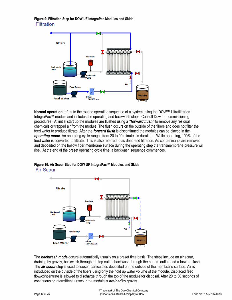
Figure 9: Filtration Step for DOW UF IntegraPac Modules and Skids
Normal operation refers to the routine operating sequence of a system using the DOWTM Ultrafiltration IntegraPac™ module and includes the operating and backwash steps. Consult Dow for commissioning procedures. At initial start up the modules are flushed using a “forward flush” to remove any residual chemicals or trapped air from the module. The flush occurs on the outside of the fibers and does not filter the feed water to produce filtrate. After the forward flush is discontinued the modules can be placed in the operating mode. An operating cycle ranges from 20 to 90 minutes in duration. While operating, 100% of the feed water is converted to filtrate. This is also referred to as dead end filtration. As contaminants are removed and deposited on the hollow fiber membrane surface during the operating step the transmembrane pressure will rise. At the end of the preset operating cycle time, a backwash sequence commences. Figure 10: Air Scour Step for DOW UF IntegraPac™ Modules and Skids
The backwash mode occurs automatically usually on a preset time basis. The steps include an air scour, draining by gravity, backwash through the top outlet, backwash through the bottom outlet, and a forward flush. The air scour step is used to loosen particulates deposited on the outside of the membrane surface. Air is introduced on the outside of the fibers using only the hold up water volume of the module. Displaced feed flow/concentrate is allowed to discharge through the top of the module for disposal. After 20 to 30 seconds of continuous or intermittent air scour the module is drained by gravity.

®Trademark of The Dow Chemical Company
Page 13 of 26 (“Dow”) or an affiliated company of Dow Form No. 795-50107-0613
Figure 11: Air Scour Gravity Drain Step for DOW UF IntegraPac™ Modules and Skids
After the gravity draining step, the first backwash step is performed. Filtrate flow is reversed from the inside of the fiber to the outside and backwash flow is removed from the module housing through the top outlet.
Figure 12: Top Backwash Step for DOW UF IntegraPac™ Modules and Skids
The second backwash step is performed to remove backwash water through the bottom outlet. Filtrate continues to flow from the inside of the fiber to the outside and backwash flow is removed from the module housing through the bottom outlet of the module, ensuring the entire length of fibers have been cleaned. The backwash steps can be repeated numerous times depending on the degree of fouling. After backwash is complete, a forward flush is performed to remove any remaining large particulates and air trapped on the outside of the fibers. After a backwash, the modules are returned to the normal operating mode.

®Trademark of The Dow Chemical Company
Page 14 of 26 (“Dow”) or an affiliated company of Dow Form No. 795-50107-0613
Figure 13: Bottom Backwash Step for DOW UF IntegraPac™ Modules and Skids
CEB operation refers to a chemically enhanced backwash. The frequency of a CEB is dependent on the feed water quality. On high quality feed waters a CEB may not be required. The CEB process is programmed to occur automatically but the frequency can be field adjusted after gaining site specific operating experience. The CEB is performed using UF filtrate and either an acid, or alkali chemical. The alkali solution can be a combination of oxidant and caustic to more efficiently clean contaminants from the membrane surface. Selection of chemicals is made according the DOW Ultrafiltration applications guidelines and understanding of the foulants in the feed water. Figure 14: Forward Flush Step for DOW UF IntegraPac™ Modules and Skids
The CEB is performed using the steps of a normal backwash except during a CEB, chemical is dosed into the backwash water and a soak step is added after the second backwash step. In addition the CEB can be performed at reduced flow, usually 50% of the backwash flux.

®Trademark of The Dow Chemical Company
Page 15 of 26 (“Dow”) or an affiliated company of Dow Form No. 795-50107-0613
Figure 15: Chemically Enhanced Backwash "Top" Step for DOW UF IntegraPac™ Modules and Skids
The soak is performed for 5 to 20 minutes and allows time for the chemical to react with contaminants that have attached to the membrane surface or penetrated the fiber wall. Intermittent air scour can be applied during the soak step. After the soak a routine backwash including air scour, gravity drain, top and bottom backwash, and forward flush is performed to remove any remaining particulates and purge residual chemicals. After a CEB and at the start of the operating step, the initial filtrate produced may be sent to waste to remove residual chemicals. This step is dependent on the system piping and valve design and the downstream requirements for the filtrate. Figure 16: Chemically Enhanced Backwash "Bottom" step for DOW UF IntegraPac™ Modules and Skids
CIP
A clean in place (CIP) is an offline operation that includes backwashes and chemical recirculation and soaking to clean the hollow fibers. The CIP is an on demand operation. It can be an automated process but is most often conducted manually. The frequency of a CIP is dependent on the feed water quality and routine fouling control strategy but can range from 1 to 6 months. Prior to a CIP the routine backwash steps including air scour, draining, backwash through the top outlet, and backwash through the bottom outlet are performed. The

®Trademark of The Dow Chemical Company
Page 16 of 26 (“Dow”) or an affiliated company of Dow Form No. 795-50107-0613
backwash steps can be repeated multiple times to remove contaminants or foulants not requiring chemical removal. After completing the backwash steps, the module is drained by gravity to remove excess water and prevent dilution of the CIP chemical solution. The CIP chemical solutions are recirculated through the modules on the outside of the hollow fibers for 30 minutes through a chemical mixing and solution tank. A portion of the recycle stream can be passed through the hollow fibers and recycled to the chemical cleaning tank. A cartridge filter is used to remove particulates from the CIP solution during recycle. Note that the CIP solution can be heated to 40ºC to improve effectiveness for removing contaminants from the hollow fibers. The CIP solution pH can be measured during the cleaning process and refreshed with chemicals to maintain the target pH and effectiveness of the solution. A soak is performed after the initial recycle step for 60 minutes or longer depending on the degree of fouling that has occurred. After the soak step, CIP chemicals are again recycled through the modules on the outside of the hollow fibers for 30 minutes. Air scour for short durations can be performed during the soak and recycle steps to prevent channeling of the solution through the module. When the recycle is completed an air scour is performed and then the module is drained to remove the concentrated chemical solution. The top and bottom backwash and the forward flush steps are also performed to remove any remaining particulates on the outside of the fibers. After a CIP and at the start of the operating step, filtrate may be sent to waste to remove residual chemicals held in the fiber or module. The CIP steps described above are for a single alkali or acid chemical solution. If both an acid and alkali cleaning are required, the CIP steps would be repeated for each chemical solution. Figure 17: Clean in Place Cleaning Step for DOW UF IntegraPac™ Modules and Skids
4.2 Pretreatment
DOW Ultrafiltration IntegraPac™ Modules and Skids designs are based on qualified feed water conditions as shown in Table 7. The UF IntegraPac™ Modules and Skids can tolerate period excursions in feed water quality as shown as the maximum allowable in Table 7. If the feed water quality is outside of the design basis range Dow should be consulted to determine if a pilot study is needed to confirm performance or if a pretreatment step is necessary. Also, if the membrane filtration system is designed and installed to the conditions below but the feed water quality is not maintained, please consult Dow Water & Process Solutions.

®Trademark of The Dow Chemical Company
Page 17 of 26 (“Dow”) or an affiliated company of Dow Form No. 795-50107-0613
Table 6: Qualified Feed Water Quality Parameters
Parameter Unit Design Basis Maximum Allowable
Turbidity NTU <50 300
TOC mg/l <10 40
Particle Size micron <1501/300 300
CODMn mg/l <20 60
Oil /Grease mg/l 0 < 2
pH continuous 6-9 2-11
Temperature oC 25 40
Cl2 continuous mg/l 0.52 200
TSS mg/l 20 100 1Required for seawater applications 2 Residual in filtrate
Depending on application, a safety screen of 100 - 300 microns is recommended on the feed before the UF IntegraPac™ Modules and Skids. In seawater applications, a strainer size of 100 – 150 microns is recommended to prevent the growth of barnacles and mussel larvae in upstream, process pipework and tanks. A variety of technologies can be used such as self-cleaning screens and filters and bag, cartridge, or disc filters. Depending on the type of water or range of feed water parameters other pretreatment processes such as oxidation, coagulation, clarification and media filtration may also be needed.
4.3 Cleaning
Summary of Information The process operating parameters for the cleaning steps are provided in Table 8 below.
Table 7: Summary of Cleaning Processes
Backwash Frequency Once every 20 to 90 minutes (water source or pilot test results)
Backwash Duration 40 to 120 seconds
Backwash Flux 80 to 150 lmh (47 – 90 gfd)
Air Scour
Maximum Inlet Pressure 2.5 bar (36 psi)
Air flow per Module 5 to 12 Nm3/h (3-7 scfm)
Duration 20 to 60 seconds per cycle
Air- Water Mix Entrance Pressure 0.35 – 2.5 bar (5 – 36 psi)
Air Quality Oil-free compressed air ISO 8573.1 Class 1 solids, Class 1 oil
Chemically Enhanced Backwash
Frequency As needed
Duration Backwash Time plus soak 5 to 20 minutes
Cleaning Solutions Acid to pH 2 / Alkali to pH 12
Clean in Place
Frequency When TMP exceeds 1.0 bar above initial TMP (at same temperature)
Duration 120 minutes (recycle and soak) or longer
Cleaning Solutions HCl, Citric, Oxalic, sulfuric to pH 2 0.1%NaOH +0.2% NaOCl to pH 12
Cleaning Flow per Module 1.0 – 1.5 m3/h (4.4 – 6.6 gpm)
Temperature Range 10 to 40 °C (50 - 104 º)

®Trademark of The Dow Chemical Company
Page 18 of 26 (“Dow”) or an affiliated company of Dow Form No. 795-50107-0613
4.4 Fouling
There are four types of fouling common to UF operations including particulate, biological, inorganic, and organic.
Particulate fouling is caused by suspended solids, colloids, and turbidity. To reduce particulates in UF feed water coagulation, sedimentation, clarification, and filtration are often used. The common cleaning method for particulate fouling is air scour and backwash.
Biological fouling is caused by the growth of microorganisms. Using in-line chemical feed of chlorine or biocide or eliminating nutrients by using PAC, GAC, or coagulation, can reduce biological fouling. The cleaning method for removal of biological fouling is Chemically Enhanced Backwash (CEB) with oxidizers or biocides (NaOCl, H2O2, SBS). Shock chlorination can also be effective for biological fouling control. Inorganic fouling is caused by the precipitation of inorganics on the membrane. The rate of inorganic fouling can be controlled through oxidation/precipitation and/or filtration as pretreatment to the UF or in some cases reducing the hardness of the feed water. The recommended cleaning method for removal of inorganic fouling is chemically enhanced backwash with acid at pH 2 (HCl, H2SO4, Citric, Oxalic Acid).
Organic fouling is caused by organics adsorbing on the membrane (silt, organic acids, humus). PAC, GAC, or coagulation can be used to control the rate of organic fouling. The common cleaning method for removal of organic fouling is CEB with alkali at pH 12 (NaOH).
5. Operating Information
5.1 Start Up
The following procedures should be followed for start-up of DOWTM IntegraPac™ Ultrafiltration Modules and Skids. Manually start the equipment during initial operation. Flush the UF system to remove the storage solution used in shipping before starting the equipment. Target a filtrate flow of 60% of design during initial operations. After 24 hours the filtrate flow can be adjusted to design conditions.
Pre-start checks
1. The UF pre-treatment system should operate properly and the UF feed water should meet the design requirements. Ensure that chemical addition points are properly located and that proper mixing of chemicals in the feed streams can occur. Check the addition of pretreatment chemicals. 2. Verify that the drain/waste collection system is functional 3. Verify that the PLC program is loaded and functioning 4. Complete an electrical system check. Verify that the instrumentation is working and calibration is completed. Calibrate gauges and meters based on manufacturers’ recommendations. 5. Clean and connect interconnecting piping. Flush system without modules to remove fabrication debris. During the flushing operation, check all pipe connections and valves for leaks. Tighten connections where necessary. 6. Residual air should be removed from the system during start-up.
Start Up
Check that all valves are closed and pumps are off before starting the system. Start the equipment by following the steps below:
1. Pumps should be aligned, lubricated, and properly rotated. 2. Open valves and start the feed pump 3. Fill system and start a flush 4. Start the backwash pump 5. Set and adjust the backwash pressure 6. Set and adjust the inlet air pressure 7. Set backwash time interval 8. Set air scour time interval 9. Set backwash sequence

®Trademark of The Dow Chemical Company
Page 19 of 26 (“Dow”) or an affiliated company of Dow Form No. 795-50107-0613
Module Rinsing The DOW IntegraPac™ Ultrafiltration modules should be rinsed prior to startup to remove storage solution shipped in the modules. Flushing should be performed until no foam is observed in the waste stream generated. Depending on the treatment application, additional rinsing or disposal of the filtrate may be required.
NSF / ANSI Standard 61 certified modules require the following conditioning rinse prior to producing potable water:
1. Rinse the modules at a feed rate of 40 LMH minimum for a period of 4 Hours.
2. Achieve a minimum total rinse volume of 160 LMH-Hours using the feed water available.
3. The concentrate bleed rate should be set between 0% and 20% with the balance being filtrate.
4. During the rinse cycle, perform standard cleaning procedures (e.g. backwash) per the design projection or Dow’s recommendations based on the feed water quality data.
5. The rinse filtrate should be sent to the appropriate disposal system based on the regulations that apply to the location where the conditioning rinse is carried out and not used as potable water.
6. Local regulations may require additional conditioning of the system prior to producing potable water.
5.2 Integrity Testing procedures
There are two methods used to perform an integrity test: a visual inspection test and pressure decay test. .
Pressure hold/decay 1. Take the UF unit or module out of the filtration mode. Drain the water from the feed side of the module.
Close the feed and concentrate valves (see Figure 18) and keep the filtrate valve open. 2. Pressurize the feed side of the membrane modules with oil free compressed air from the air inlet valve,
and slowly raise the air pressure to a maximum of 2 bars (29 psi). A minimum test pressure of 18 psi will allow detection of 3 micron particles. Expect some water to flow from the hollow fibers to the filtrate.
3. Close the air inlet valve and allow the pressure to stabilize 4. Hold the pressure for 10 minutes. The membrane is integral (no leaks) if the pressure drop is lower than
0.2 bar (2.9 psi). If the pressure drop is greater than 0.2 bar in 10 minutes (2.9 psi in 10 minutes) then membrane fibers might be compromised and require repair.
5. Repair the membrane following the “fiber test and repair procedure”. Visual Inspection Test
During the pressure hold/decay test, leaking modules can be identified through the transparent section of filtrate
piping. As the system is being pressurized with oil-free compressed air from the air inlet valve at a maximum of 2
bars (29 psi), large continuous air bubbles may appear in the transparent filtrate piping. This indicates that the
specific module may have broken fibers or damaged seals. Smaller and infrequent bubbles are the result of air
diffusion through the pores of the ultrafiltration membrane.

®Trademark of The Dow Chemical Company
Page 20 of 26 (“Dow”) or an affiliated company of Dow Form No. 795-50107-0613
Figure 18: Pressure Hold Test Schematic
5.3 Shut Down
Manual shut down To conduct a manual shut down open the concentrate rinse valve and flush for 15 seconds. Then stop the feed pump and slowly close the inlet valve. Equipment shut down during automatic operation The equipment will automatically stop or will not allow automatic operation if the feed pump did not start when operation was initiated or the inlet or filtrate pressure is too high to operate or there is a loss of power. Valves should fail closed.
Please refer to the module storage and preservation steps before shutdown to allow proper module maintenance be performed.
5.4 Operating and Cleaning Logs
Recording data is useful for tracking operating conditions and to optimize operations. The frequency of data collection will depend on the use of the filtrate water or regulatory requirements. Attached are two logs including the Data Log Sheet for normal filtration and operations and the CIP Record Sheet, which is used to collect information from the Clean in Place process.

®Trademark of The Dow Chemical Company
Page 21 of 26 (“Dow”) or an affiliated company of Dow Form No. 795-50107-0613
DOWTM Ultrafiltration Data Log Sheet
Customer:
System Information: (pretreatment process, chemical feed type and dosages, etc):
UF Module Type: Number of Skids: Number of Modules/skid:
Membrane Area:
Date: Time: Cumulative hours of operation:
Recorded By:
Parameters Unit Recorded Value Comments
Data Collected
Temperature (T) ºC or ºF
Pre-filter Inlet Pressure Psi or bar
Pre-filter Outlet Pressure Psi or bar
UF Feed Pressure (Pf) Psi or bar
UF Filtrate Pressure (Pp) Psi or bar
UF Concentrate Pressure (Pc) Psi or bar
UF Filtrate Flow / skid (Qp) gpm or m3/hr
UF Backwash Flow / skid (Qbw) gpm or m3/hr
UF Forward Flush / skid (Qff) gpm or m3/hr
Filtration time per cycle (tf) minutes
Backwash time per cycle (tbw) seconds
Forward flush time per cycle (tff) seconds
Air Scour time per cycle seconds
CEB Alkali frequency hours
CEB Alkali pH ---
CEB Acid frequency hours
CEB Acid pH ---
UF Feed Turbidity NTU
UF Filtrate Turbidity NTU
UF Feed TSS ppm or mg/L
UF Filtrate TSS ppm or mg/L
UF Filtrate SDI15 ---
Performance
Gross Flux (J) Gfd or lmh
Transmembrane Pressure (TMP) Psi or bar
Permeability (LN, 20) Gfd/psi or lmh/bar
Equations to Calculate Performance
Transmembrane Pressure (TMP) = Pf - Pp
Recovery (R) = (Qp* tf - Qbw* tbw) / (Qp* tf + Qff * tff) * 100

®Trademark of The Dow Chemical Company
Page 22 of 26 (“Dow”) or an affiliated company of Dow Form No. 795-50107-0613
DOWTM Ultrafiltration CIP Record Sheet
Customer:
System Information: (pretreatment process, chemical feed type and dosages, etc)
UF Module Type: Number of Skids:
Number of Modules/skid:
Cumulative hours of operation:
Total number of cleaning:
Date: Time: Cumulative hours of operation after last cleaning:
Recorded By:
Item Unit First Solution Second Solution Remarks
Pre-cleaning Air Scour and Backwash
Backwash Water Source ---
Backwash Flux LMH or gfd
Air flow rate per module Nm3/h or scfm
Cleaning Chemicals
Volume of cleaning solution Liters or gallon
Acid (also list type used) Liters or gallon
Caustic soda ( %) Liters or gallon
Sodium hypochlorite ( %) Liters or gallon
Others Chemicals Liters or gallon
CIP Operating Conditions
Solution concentration %
pH ---
Temperature ºC or ºF
Circulation flow rate m3/h or gpm
Duration of initial circulation Minutes
Soaking period Minutes
Duration of final circulation Minutes
Final Backwash or Flush/Rinse
Source of water ---
Flow rate m3/h or gpm
Duration Minutes
pH of waste streams ---

®Trademark of The Dow Chemical Company
Page 23 of 26 (“Dow”) or an affiliated company of Dow Form No. 795-50107-0613
For more information about DOW IntegraPac, call the Dow Water & Process Solutions business: North America: 1-800-447-4369 Latin America: (+55) 11-5188-9222 Europe: 800 3 694 6367 Italy: 800 783 825 South Africa: 0800 99 5078 Pacific: +800 7776 7776 China: +800 889 0789 India: +91 22 6674 1500 www.dowwaterandprocess.com
Notice: No freedom from infringement of any patent owned by Dow or others is to be inferred. Because use conditions and applicable laws may differ from one location to another and may change with time, Customer is responsible for determining whether products and the information in this document are appropriate for Customer’s use and for ensuring that Customer’s workplace and disposal practices are in compliance with applicable laws and other governmental enactments. The product shown in this literature may not be available for sale and/or available in all geographies where Dow is represented. The claims made may not have been approved for use in all countries. Dow assumes no obligation or liability for the information in this document. References to “Dow” or the “Company” mean the Dow legal entity selling the products to Customer unless otherwise expressly noted. NO WARRANTIES ARE GIVEN; ALL IMPLIED WARRANTIES OF MERCHANTABILITY OR FITNESS FOR A PARTICULAR PURPOSE ARE EXPRESSLY EXCLUDED.