integrate multiple motors enhance designs improve … · the rotor pressed onto the stator,...
TRANSCRIPT

Integrating rotary movement and electronics An SMD-mounted piezo motor
PCBMotor ApS | Krakaksvej 17, 3400 Hillerod, Denmark | T. +45 7028 3210 | www.pcbmotor.com Email Henrik Staehr-Olsen at [email protected]
Integrate multiple motors
Enhance designs
Improve accuracy
Reduce production costs
PCBMotor
See our introduction video on www.youtube.com/pcbmotor

Integrate multiple motors on one PCB
Enhance product designs and reduce building height
Improve precision through ultra-high resolution
Lower assembly costs with automatic mounting
Non-magnetic
Fast start & stop actions
Optional position sensor
www.pcbmotor.com Proprietary Q1 2011 2
Direct drive, no gears, slack-less
High torque and holding torque
Built-in clutch, tamper proof/safe
Competitive advantages & increased profit
Four new ways to succeed
Key features

www.pcbmotor.com Proprietary Q1 2011 3
Medico
Microscope focus
Dosing equipment
Optics & Lasers
Camera
Focus
Pan, tilt & zoom
Instrumentation
Dashboard pointers
Positioning, stages
Laboratory equipment
Industrial
Valve application
Application examples
3
Ultra-high resolution & accuracy

Creating movement right on the PCB
www.pcbmotor.com Proprietary Q1 2011 4
A PCBMotor consists of
1. The Stator
The PCB with piezos mounted, to which a voltage is applied, thus causing the traveling wave
2. The Rotor
Pressed onto the stator, delivers the mechanical output
Turn your PCB into a motor
See the traveling wave on our Youtube channel: http://www.pcbmotor.com/pcbmotor

Flexible designs Automated assembly
www.pcbmotor.com Proprietary Q1 2011 5
Industry standards ensure economies of scale
Smaller, lighter, more compact designs
Application-specific rotors. Our solutions accommodate variable rotor widths and heights, thus allowing more flexible application designs
The control driver. Can be integrated onto the same PCB as the stator
Fully-automated production that
Employs electronic-industry manufacturing standards
Uses ”landing bridges” to connect the stator to the driver Piezo ceramics mounted as SMD components
Pick & Place robotics with rotary head

www.pcbmotor.com Proprietary Q1 2011 6
Motor characteristics Source: PCBMotor, measured result
400
420
440
460
480
500
520
540
15
16
17
18
19
20
21
22
23
20 30 40 50 60 70
mA
Nm
m
Dgr C
Stall Torque vs TemperatureØ30 Stator 2009-40-63
Mean Stall Torque
Mean Resonance Current
Motor performance results
An operating temperature range of -10 to 85 °C has been tested and confirmed in some applications.
Motor characteristics for a Ø30 mm stator measured at 200 Vrms. Maximum available power at the shaft is 80 mW at a speed of 1 rev/s. Notice the linear Torque/Speed curve.

0
50
100
150
200
250
1 161 321 481 641 801 961 1121 1281 1441 1601 1761 1921 2081 2241 2401 2561 2721 2881 3041 3201 3361 3521 3681 3841
Mo
tor
cu
rren
t (m
A)
10 minute time intervals
666hrs Life test at room temperatureØ30 motors, alternating CW-CCW. 13-04-2010 15:28:46
w7-2
RodaAg-1
w11-bf-1
w11-bf-2
w11-bf-3
Endurance test results
The above results were compiled from a Ø30 mm motor running continuously, logging data every 10 min. Note: The experiment shows no changes (End-of-life) in the given timeframe.
PCBMotors are well-suited for customer integrations. Our motors have an expected life of >1000 hrs. The final application and its actual operating environment ultimately determine the motor’s life expectancy.
www.pcbmotor.com Proprietary

www.pcbmotor.com Proprietary Q1 2011 8
Superior resolution with up to 2,6M µpulses/revolution Utilizing open-loop and micro-pulsing the controller, system engineers can now achieve superior micro-positioning in applications with resolutions over 2.6 million µpulses per revolution.
Increased resolution gives greater accuracy
High-precision applications
Technology experiment record The controller is open-loop, i.e. the µpulses are entirely “free-running”. In a practical application, external feedback is needed to determine the position. The digital codewheel can be used for calibrating µpulses/step for each digital step.
Watch the high resolution technology record on our Youtube channel: http://www.youtube.com/pcbmotor

Rotor & hollow shaft examples
www.pcbmotor.com Proprietary Q1 2011 9
12 mm ‘free center’ using a rotor disc for Ø30 mm stator with spring & sensor markings.
Interlocked rotor discs for maximum ‘free center’ diameter.
3-point roller support principle for radial alignment.
Hollow 60 mm rotor construction with 3 rollers.
High resolution and low cost hollow shaft
Locking mechanism
Encoder
Spring
Piezo
PCB
PCB Top View
Roller
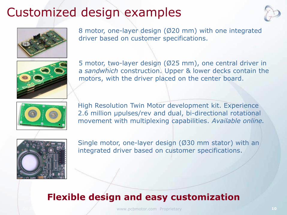
Customized design examples
www.pcbmotor.com Proprietary Q1 2011 10
8 motor, one-layer design (Ø20 mm) with one integrated driver based on customer specifications.
5 motor, two-layer design (Ø25 mm), one central driver in a sandwhich construction. Upper & lower decks contain the motors, with the driver placed on the center board.
High Resolution Twin Motor development kit. Experience 2.6 million µpulses/rev and dual, bi-directional rotational movement with multiplexing capabilities. Available online.
Single motor, one-layer design (Ø30 mm stator) with an integrated driver based on customer specifications.
Flexible design and easy customization

Basic control driver (without position sensor)
www.pcbmotor.com Proprietary Q1 2011 11
The driver generates a two-phase sinusoidal that is stepped up through two transformers to a drive voltage of 50- 200 Vrms.
0.2-2.0 W power for Ø30mm motor
Motor resonance: 40-45 kHz
Frequency Tracking needed for max performance at different temperatures
1 Central control driver can drive several motor positions, with application electronics on the same PCB
The basic component in the driver is the transformers
Standard IC’s or ASIC are possible for applications with space constraints
Low cost, flexible drivers - smaller through IC’s
www.pcbmotor.com Proprietary Q1 2011 12
Next steps for application success
For more information email [email protected]
NEED MORE FACTS ABOUT OUR PIEZO TECHNOLOGY?
Download our White Paper – How to Solve High Resolution and Low Speed Dilemmas. Includes a free engineering consultancy session and The Top 5 Pains electronic movement designers and engineers have today!
IS YOUR APPLICATION PCBMOTOR-READY?
To hear if your application is right for a PCBMotor, fill out the Performance Sheet on slide 13 and send it to me.
www.pcbmotor.com Proprietary Q1 2011 13
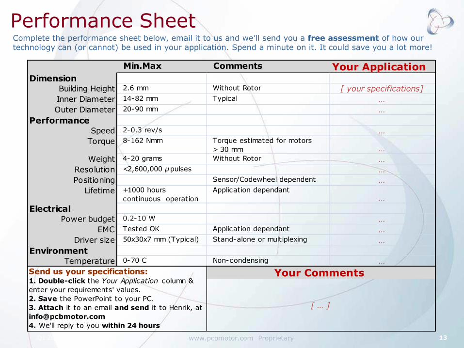
Performance Sheet Complete the performance sheet below, email it to us and we’ll send you a free assessment of how our technology can (or cannot) be used in your application. Spend a minute on it. It could save you a lot more!
Min.Max Comments Your Application Dimension
Building Height 2.6 mm Without Rotor [ your specifications]
Inner Diameter 14-82 mm Typical …Outer Diameter 20-90 mm …
PerformanceSpeed 2-0.3 rev/s …
Torque 8-162 Nmm Torque estimated for motors
> 30 mm …Weight 4-20 grams Without Rotor …
Resolution <2,600,000 µpulses …Positioning Sensor/Codewheel dependent …
Lifetime +1000 hours
continuous operation
Application dependant…
ElectricalPower budget 0.2-10 W …
EMC Tested OK Application dependant …Driver size 50x30x7 mm (Typical) Stand-alone or multiplexing …
EnvironmentTemperature 0-70 C Non-condensing …
Your Comments
[ … ]
Send us your specifications:1. Double-click the Your Application column &
enter your requirements' values.
2. Save the PowerPoint to your PC.
3. Attach it to an email and send it to Henrik, at
4. We'll reply to you within 24 hours

PCBMotor ApS – service & support
High Resolution Twin Motor Kit The 2.6 million High Resolution Twin Motor Kit includes a main motor board, controller board, & free PCBMotor software for speedy integration and prototyping.
Lab Kit Basic A Lab Kit is the best way to get started with using PCBMotor technology and comes with everything you need.
www.pcbmotor.com Proprietary
Browsse our online shop for more about our evaluation kits for application designers and electronic engineers.
Go to www.pcbmotor.com/demo-kits
Evaluation Kit Basic Evalulation kit with tracking feature for demonstration and project preparation.