integrated in-wheel motors for low power traction...
TRANSCRIPT

INTEGRATED IN-WHEEL MOTORS FOR LOWPOWER TRACTION APPLICATIONS
PRAKASHRAJ KASINATHAN
Department of Electric Power Engineering
CHALMERS UNIVERSITY OF TECHNOLOGY
Gothenburg, Sweden,
2003

2
THESIS FOR THE DEGREE OF DOCTOR OF PHILOSOPHY
INTEGRATED IN-WHEEL MOTORS FOR LOW POWERTRACTION APPLICATIONS
PRAKASHRAJ KASINATHAN
Department of Electric Power Engineering
CHALMERS UNIVERSITY OF TECHNOLOGY
Gothenburg, Sweden
2003

3
INTEGRATED IN-WHEEL MOTORS FOR LOW POWERTRACTION APPLICATIONS
PRAKASHRAJ KASINATHANISBN 91-7291-268-5
PRAKASHRAJ KASINATHAN, 2003
Technical report No. 445School of Electrical EngineeringElectrical Machine and Drive Systems GroupChalmers University of TechnologyNy serie nr 1950ISSN 1651-498X
Department of Electric Power EngineeringElectrical Machines and Drive Systems GroupChalmers University of TechnologySE-41296 GöteborgSweden
FRONT COVER: REPRODUCE COURTESY OF SUNRISE MEDICAL
Chalmers Bibliotek, ReproserviceGöteborg, Sweden 2003

4
1.1. ABSTRACT
This thesis is primarily concerned with the practical limits, imposedby magnetic saturation and thermal considerations, of the forcedensity in low-speed permanent-magnet electric machines. Thepractical force density values obtainable in integral- and fractional-slot machines are determined. The achievable force density formachines utilizing slot per pole per phase of 0.375, 0.5, 0.75 and 1are determined. The theoretical investigation covered a large rangeof machine sizes.
For saturation reasons, shallow slots are more favourable forachieving high force densities. However for thermal reasons deeperslots become favourable. An optimum slot depth that maximises theforce density for each current density level therefore exists and isdetermined in this thesis for a range of machines. In particular, themaximum allowable slot depth range for four low-speed applicationsare identified for a given maximum motor diameter.
Plots of the force density against slot depth for various currentdensities for fixed pole pitches enabled a useful database to beestablished. These curves would enable one to determine if thedemanding specification can be meet within a given restricted space.The slot depth required can be determined instantly for the practicalallowable current density.
The results presented will help the design engineer to determine ifthe surface mounted permanent magnet machine configuration issuitable to fulfil one’s specification. If the configuration is notsuitable, then other topologies must be considered.
An experimental in-wheel motor, intended for wheelchairapplications, was built and tested, and is shown to meet the designspecifications. When assembled into the wheelchair the results were

5
promising and showed a remarkable increase in performancecompared to the existing conventional geared drive.
1.2. KEYWORDS
• Traction motors• Force density• Direct-drive• Low speed machines• Flux-linkage• Integral-slot• Fractional-slot• Electric wheelchairs/Power wheelchairs• Electric golf cart• Forklift trucks

6
Acknowledgements
The author is very grateful to the UK’s Centre For AdvancedElectronically Controlled Drives for financing his work while atCardiff University and acknowledges the centre members forbuilding the electric wheelchair prototype. The author is extremelygrateful to the Rector of Chalmers, Professor Jan-Eric Sundgren formaking available the necessary finance that enabled completion ofthe PhD work in Sweden.
The author is very grateful to his examiner and supervisor ProfessorEssam Hamdi for providing an enjoyable work environment and forinvaluable help and guidance throughout his University study. Theauthor wishes to applaud the abilities of Professor Hamdi as anacademic and tutor.
The author wishes to express his heartfelt thanks to his supervisor atChalmers, Dr Anders Grauers, with whom the collaborationthroughout this thesis was extremely valuable.
The author wishes to thank his former colleague at CardiffUniversity, Dr John Dolan with whom views were exchanged onmany topics. Thanks are also due to Paul Farrugia for assisting inmany computing, software and other technical matters.
Finally, the author wishes to thank all his fellow PhD students atChalmers. In particular, he wishes to give a specialacknowledgement to his colleagues at the Machines and DriveSystems Group and regrets to inform them that his name will,hopefully, be removed from the Monday Lunch rota soon.

7
Table of ContentChapter 1: Introduction
Abstract iAcknowledgement ii
1. Introduction1.1. Background and motivation 11.2. Battery powered electric vehicles 31.3. Motor rating and system voltage 61.4. Requirements of low power traction 71.5. Transmission options 71.6. Assesment of brushless direct-drive design 101.7. Scope of this thesis
12
Chapter 2: Permanent Magnet Motors2.1. Introduction 152.2. Permanent magnets 17
2.2.1. Alnico magnets 192.2.2 Ferrite magnets 20
2.2.3 Rare earth magnets21
2.3. Motor topologies 232.3.1. Conventional dc motors 242.3.2. Switch-reluctance drives 252.3.3. Brushless drive systems 27
Brushless dc and permanent magnetsynchronous motors 30Rotor magnet configurations 31
2.3.4. Other types of PM motors 33Printed motor(Flat armature pancake motor) 34Hollow rotor motor 36Stepper motor 36Slotless axial flux PM motor 38
2.4. Motor selection 40
Chapter 3: Force Density Limits In Integral Slot Machines
3.1. Introduction 413.2. Scope of investigation 43

8
3.3. Force density 443.4. Saturation limits 46
3.4.1. Models description 463.4.2. Simulation procedure 503.4.3. Effect of magnetic non-linearity 533.4.4. Achievable force density values 55
3.5. Force density variation with winding currentdensity 60
3.6. Force density and flux-linkage 643.7. Applications 72
Chapter 4: Force density limits in fractional-slot machines
4.1. Introduction 754.1.1. Armature winding for ac machines 764.1.2. Winding factor 78
Distribution factor 79Coil pitch factor 80
4.1.3. Fractional-slot windings 814.2. Model description 834.3. Continuous and transient force density 834.4. Force density variation with winding currents 90
Chapter 5: Design and experimental evaluation5.1. Design specifications 915.2. Design considerations 94
5.2.1. Stator lamination 955.2.2. Slot shape 965.2.3. Stator winding 965.2.4. Rotor design 96
5.3. Wheelchair motor 965.3.1. Number of poles 985.3.2. Prototype design 99
Stator assembly 100Rotor construction
103Position sensing 106Effect of skewing
1075.3.3. Testing 108
5.4. Forklift truck motors 111

9
5.4.1 Effect of skewing 1145.4.2 Summary of proposed designs 1195.4.3 System voltage 120
Chapter 6: Conclusion and future work6.1. Conclusions and future work 1216.2. Recommended future work 123
PUBLICATIONSAppendix I
Paper A 125-150
A.Grauers, P.Kasinathan, “Force Density in Low-speed PM:Temperature and Inductance limits”, Proc. 2003 IEEE PowerEngineering Energy Conversion.
Paper B 151-176
P. Kasinathan, A Grauers and E Hamdi "Force Density inLow-speed PM Machines: Saturation limits." Proc. 2003 IEEEPower Engineering Energy Conversion
Appendix II
Integral-slot designs 177-186[Force density Vs Slot Depth curves for various pole pitch]
Appendix IIIFractional-slot design 187-210[Force density Vs Slot Depth curves for various pole pitch]
REFERENCES 211-215

10

11
CHAPTER I
INTRODUCTION
1.3. BACKGROUND AND MOTIVATION
For traction applications, the short-term rating, which governsacceleration and hill-climbing ability, is possibly as important as thecontinuous rating. By virtue of its overload capacity, the electricmotor is superior to the petrol engine in performance because thelatter cannot utilise its full rated power at all times. For this reason, a11kW electric motor is able to replace a 30 kW petrol engine, givingalmost the same performance [1].
One of the main objectives of the development of traction motors isreduction of specific weight, which is somewhat high at about 6 to 9kg/kW for continuous rating, improving to about half these valuesfor peak rating. Traditionally, the dc motor has been widely used asthe main propulsion motor for battery-powered road and industrialelectric vehicles. While the series-wound type yield the ideal torqueversus speeds characteristics for the majority of applications, the dccompound motor has found a niche in some industrial trucks whereelectric braking is required.

12
The main drawback of dc motors is of course their maintenancerequirements. Consequently, constant efforts are being made todevelop alternative type of drive systems with equally or almost asgood characteristics, but without commutator or brushgear.Continuous development of semiconductor switching devices andpower electronic converters has made it possible to meet the tractionrequirements for many applications by an induction motor drivesystem.
It should be noted that ac motors would give higher specific outputthan the dc motor. The possible weight-to-power ratios, includingthe gearbox, inverter and cooling arrangements, of a high-speedsquirrel-cage induction motor (10,000 to 20,000 rev/min) could beabout 2 kg/kW at continuous rating [1].
In recent years, attention has been focused on further reducing themaintenance requirements, especially in low-power tractionapplications. Removal of the gearbox is seen by a number ofmanufacturers of wheelchairs and forklift trucks as the next step inreducing maintenance requirements and increasing systemreliability. This is of course no mean challenge. The motor would beeither directly coupled to the wheel shaft or incorporated within thewheel itself. Either way, the motor speed would be much lower thanthat of a geared drive and this would require the designer to aim formuch higher power-to-weight ratios than hitherto been required. Infact, the designer would be working on the edge of presenttechnology; i.e. the system would need to be designed as close to thetheoretical limits of achievable force density as is practicallypossible. To this end, the work presented here provides a databasegiving the maximum achievable force density for a range of currentdensities and pole-pitches. It enables the designer to readily establish

13
whether or not certain traction requirements can be met, at leasttheoretically, with present day technologies and materials.
In order to demonstrate the practical significance of research work,the force density limits are used to design integrated in-wheel drivesfor a number of low power traction applications. The work alsoincludes experimental evaluation for one such drive intended forwheelchair applications.
1.4. BATTERY POWERED ELECTRIC VEHICLES
There are many types of totally battery powered electric vehiclescurrently available in the market. They can be divided into 3 broadcategories: light electric vehicles, medium electric vehicle and heavyelectric vehicles. Within each category there are sub categoriesconsisting of many different models with their own advantage anddisadvantages. Figure 1.1 lists some of the applications that fall intothese sub categories. The electric drive technology based on themotorised wheels can be used in different types of vehicles (withone or two drive wheels, or with full drive). Although there aremany suitable applications, in this thesis only the electricwheelchairs, golf carts and forklift trucks are considered.
At present a typical propulsion system for an electric wheelchairconsists of a pair of brushed dc internally rotating permanent magnetmotors; one for each drive wheel. The shunt and series motors havebeen the prime candidates for the forklift truck and golf carts as theirtorque and power characteristic meet the application requirements asthe speed can be easily controlled with these motors. Each motor iscoupled to the rear wheel through a reduction gearbox and a breakunit.

CHAPTER I: BATTERY POWERED ELECTRIC VEHICLE
14
Figure 1.1: Classification of battery-powered electrical vehicles.
Light ElectricVehicle
Medium ElectricVehicle
Heavy ElectricVehicle
-Childrens
Electromobiles
-Golf carts-Wheelchairs-Buggies
Power Range40 to 300 W
-Tripple wheel bicycle-Minicar-Motoroller-Scooter-Electromobile-Electric Bicycles
Power Range300 to 4 kW
-Tractors-Microbus,-Electric Bicycles-Trolley bus-Electric locomotive-Electric Vehicle-Lorry-Forklift trucks
Power Range1.5 to 40 kW
Electric Vehicle Categories

15
The gear train, apart from being a shock absorber when the drivewheels are stuck or under heavy load, serve to reduce the motorspeed while proportionally increasing motor torque. This result in asignificant reduction of required motor volume leading to a lowermanufacturing cost.
However, useful as they are, the conventional dc electric motorsused in the present propulsion system for these applications have anumber of limitations. The available conventional dc motors operatewith mechanical systems of gears and brushes. As a consequence,these mechanical systems are the weakest link of the electric vehicleand are too expensive to maintain. The chatter and swiping of gearsand the friction associated with motor and idler bearings arepotential sources of vibration and noise. As with any mechanicalsystem, parts wear, break and need to be serviced. Brushes and gearswear due to friction and the grease used to overcome frictionproblems is prone to leaking and can lead to expensive clean upcosts. The failure of these component results in the vehicle beingreturned to the manufacturer for regular inspection and replacementresulting in the users paying high maintenance costs. Hence manyusers operate their motor until failure and purchase a replacementmotor unit in preference to being both inconvenienced and payinghigh maintenance costs.
In order to overcome these problems and replace the mechanicalsystem of the conventional dc motor of these vehicles the systemneeds to have no gears, brushes or grease. Hence the system has tohave no touching parts. The brushless motor technology would makeit possible to achieve these requirements.

CHAPTER I: MOTOR RATING AND SYSTEM VOLTAGE
16
1.5. MOTOR RATING AND SYSTEM VOLTAGE
The nominal kilowatt rating for traction drive motors is usuallyrelated to a one-hour operating period plus an overload of 200%full-load torque for a period in the order of 5 minutes, withtemperatures of the windings remaining within the limits prescribedin the relevant standards for the insulation system used.
High-voltage systems obviously require less current, for the sameoutput, than low-voltage systems. This is advantageous as far as thecontroller is concerned. Also, as the system voltage is increased,electrical power loss throughout the entire circuit from the battery tothe motor armature will be reduced. Clearly, one of the mostimportant factors in designing battery-operated vehicles, in general,is the system efficiency, or more accurately losses. Typically, 1 kWhof lost energy requires the carriage of an additional lead-acid batteryweight of some 25 to 30 kg. For example, it is expected that therewould be a reduction in power losses of about 10 to 15% when atruck is changed from 24 to 36 V [1]
For a given motor peak power requirement there exists a range ofpossible voltages which would provide for a satisfactory batterypack. However, sensible values of maximum currents tend to limitthis range to some extent. Also, safety considerations tend to limitmaximum voltage especially in applications such as wheelchairs.Hence some sort of compromise has to be arrived at.
The nominal voltages most used in low power traction systems are12, 24, 36, 48, 72 and 80. High voltages of several hundreds of voltsare possible in road vehicles, such as buses and passenger cars. Thisis because such vehicles are serviced by skilled personnel who willbe aware of the dangers associated with such systems.

17
Wheelchairs normally operate on 24 V systems while most golf cartsand similar vehicles operate on 36 or 48 V. Within the sphere ofindustrial electric trucks the trend is towards high-voltage drivesystems. Here, the term high-voltage applies to the high side of theavailable voltage spectrum for a particular truck type. Rider-operated forklift trucks normally operate on 48 or 72 V systems. Itshould be noted that some rider operated trucks and most pedestrian-operated trucks operate on lower voltages than 48 V.
1.6. REQUIREMENTS OF LOW POWER TRACTION
The proposed electric motor replacing the existing conventional dcmotors currently used must be powerful enough to satisfy thetraction requirements, but this is not the only criterion. Thefollowing lists some of the main requirements that must be fulfilledto enable the widespread use of proposed electric motors for allthese applications.
1. The motor should be small and lightweight.2. High economical efficiency.3. Durable and easy to maintain.4. Low noise.5. Low cost.6. Must be able to be used under various conditions and humidity.7. Regenerative braking.
1.7. TRANSMISSION OPTIONS
The drive train is a mechanical system that transfers power from themotor to the drive-wheels. The conventional drive train is composedof gears, belts, chains and other mechanical elements that serve toreduce motor speed while proportionally increasing the motor

18
torque. Motor and drive train efficiency impacts battery performanceand the overall performance of the system. Weather these vehiclesare suitable for the appropriate tasks are determined by thecharacteristics of its motor, drive train, battery and powermanagement system.
Figure 1.2 illustrates different possible ways that can be adopted totransfer power from the motor to the wheels. Some are easier andcheaper to build then the others. Each type presents advantages anddisadvantages. Deciding which is the most appropriate configurationfor traction purposes depends on the specific applicationrequirements.
Belt drive configurations require specific belt tension and alignmentto ensure smooth operation. If the belt tension is not set properly,this will cause slippage. Overtime, belts tend to stretch and willeventually slip around the pulley’s circumference. The fatigue ofbelts and bearings can reduce tension, requiring re-tensioning. Inorder to avoid these, frequent checks must be made and this willbecome too cumbersome. On the other hand, extensive tension leadsto bearing failure and inconsistent gear reduction. The effects willmanifest itself in the drive system non-repeatability, low efficiency,shorter machine life and performance problems. Chain drives aresimilar to belt drives configuration. The following lists theiradvantages over belt drive.
1. Longer life.2. No slippage between chain and sprocket due to the sprocket
tooth.3. Ability to operate in high temperatures, moisture, oil and dirt
environments.4. They only require a few sprocket teeth for effective engagement.

19
5. The tendency to stretch over time not possible due to the hightensile strength of the steel chain and sprocket.
6. They allow higher reduction ratios than belts, translating to higheroutput torque and increased load carrying capabilities.
Figure 1.2: Power transfer options.
However apart from being limited to a single plane, chain drivesoperate at considerably much higher noise levels compared to beltsor geared sets. Usually when the worn chains are replaced, the
Transmission Methods
Direct-Drive Indirect-Drive
Geared Drive-Worm gear-Bevel gear
-Spiral bevel gear
Belt & PulleyDrive
Chain Drive Friction Drive
In-WheelMotor
Shaft DrivenWheel

20
sprocket also needs to be replaced. The belt sheaves usually exhibitvery little wear and usually do not require replacement. Both chainand belt drives requires frequent oiling and are also hard to install.Thus the long term cost on both of these drives are high.
Friction drives are usually not used in any of the electric vehiclecategories. Friction losses generate heat and a non-efficient and non-economical drive system will result. The most common type oftransmission used in wheelchairs, golf carts and forklift trucks arethe geared and direct-drive design with the earlier still dominating.However among the six mentioned the simplest type of transmissionis the direct-drive design. The last few years have seen manydevelopments in direct-drive technology. Although direct-drive arenot suitable for every application, their attractive inherent propertieshave made them a prime candidate for traction purposes. Anincreasing need exist for such drives in many industrial processes asthe elimination of transmission mechanisms have proven to improveraggedness, efficiency and control precision. Overall, all mentionedadvantage listed in the next section together with the simpleconstruction of the motor-wheel make the drive exceptionallyprofitable and competitive industrial product in relation tomanufacturing expenses and unit costs.
1.8. ASSESSMENT OF BRUSHLESS DIRECT-DRIVE DESIGN
The advantages offered by a direct-drive employing a brushlesssystem over the conventional geared drive design are summarised asfollows:

21
1. With direct-drive the motor is connected directly to the axle ofthe driven wheel resulting in both motor and wheel speedbeing equal.
2. There is no mechanical power transfer by friction wheels orbelts. Thus mechanical wear and tear is eliminated. Since thewheel is rigidly coupled to the motor there are no transmissionerrors such as backlash, belt stretch and gear tooth error. Sincethere is no mechanical friction, less power is consumed. Thus ahigh economical efficiency is achieved due to the low powerconsumption. There will not be error in the speed feedbacksystem due to gear slippage. Internal stresses between bearingsare also eliminated.
3. With fewer moving parts, they offer reduced audible noise.Zero maintenance is required, as the bearings are the onlywearing component.
4. The relatively high friction, high compliance transmissioncomponents that commonly cause stick-slip in traditionallymechanical transmissions are eliminated in direct-drivesystems.
5. Since the coupling between the load and motor is stiff,problems associated with mechanical resonance are eliminated.In direct drive systems the load inertia can be many timesgreater than the motor inertia without degrading the systemperformance.
5. The usage of the motorised wheel, apart from enabling thecomplete elimination of the transmission components, reducesthe current during the start and acceleration.

22
6. The controller becomes much simplified in direct-drivesystems as the movement regime does not need optimisation.
Of course, as with most engineering problems, the advantagesoffered by direct-drive systems are offset by certain disadvantages.These are summarised in the following:
1. Since direct-drive systems have no transmission components,they must provide more torque at a lower speed compared tothe geared version. This will require more expensive magneticmaterial with higher number of poles and coils which makes itlarger in diameter.
2. They are usually much expensive than traditional transmissionsystems especially in applications requiring high torque. Thecost penalty has to be weighed against improvement in overallsystem performance in deciding the viability of direct-drivesfor a given application.
1.9. SCOPE OF THIS THESIS
The thesis deals with the design of brushless dc geared and direct-drive design for electric wheelchairs, electric golf carts and forklifttrucks. Various slot and pole combinations are investigated and anumber of designs fulfilling industrial specification are provided.The thesis presents a design and an experimental evaluation of adirect-drive in-wheel motor for a wheelchair application. Thecomparison between fractional and integral slot design are made andthe suitability of a fractional-slot machines for these applications isevaluated.

CHAPTER IV: FORCE DENSITY LIMITS IN FRACTIONAL-SLOT MACHINES
76
The thesis is organised into six chapters. Following thisintroduction, chapter 2 reviews and critically assesses differentmachines topologies which may be suitable for traction applications.Upon considering the forklift truck requirements, it became obviousthat such an application requires extremely high force density. Toenable the designer to establish if the traction requirements can bemet within available space envelope, the force density achieved forvarious machine designs are determined. The effect that magneticsaturation has on the achievable force density is investigated.Various current densities are assumed and the slot depths abovewhich any increase in slot current does not yield an increase in forcedensity, due to saturation, is determined for various pole-pitches.The investigation includes both integral-slot and fractional-slotdesigns. Both surface and inset magnet rotor configurations areconsidered. In the fractional-slot design slot per pole per phase of0.375, 0.5 and 0.75 are considered. In the inset rotor configuration,the computation included pole arcs of 120, 150 and 170 electricaldegrees. This work is presented in Chapters 3 and 4 for the integral-slot and fractional slot designs, respectively.
Chapter 5 deals with direct-drive design for electric wheelchairs,golf carts and forklift trucks. Various design having different slotand pole combinations that meet the performance requirements arepresented and an experimental wheelchair drive is developed andevaluated.
The conclusions of the present work and recommendation of furtherinvestigations are given in Chapter 6.

77

CHAPTER IV: FORCE DENSITY LIMITS IN FRACTIONAL-SLOT MACHINES
78
CHAPTER II
PERMANENT MAGNET MOTORS
1.10. INTRODUCTION
One area in which important technical advances have been made inrecent years is that of magnetism. The properties of magneticmaterials have been profoundly improved and permanent magnetshave become a vital part of present day life.
Unlike soft magnetic materials, magnets are able to hold theirmagnetic charge after being removed from the magnetizing device.This feature, have made permanent magnets very attractive for alarge number of applications [6-10]. These applications can beclassified as follows:
1. Electro-mechanical energy conversion: in these applicationselectrical energy at the input causes relative movement of themagnets resulting in the desired mechanical output.Alternatively, the relative movement of the magnets, withrespect to an electric circuit, produces an electrical output.
2. Magnets can be used to lift and hold magnetic objects, and/orapply a repulsive force.

79
3. Magnetic field can be used to control, shape or direct an objector substance.
By replacing the electromagnets with permanent magnets, toproduce the air-gap flux for example, significant performanceimprovements and benefits, such as higher efficiency and powerdensity, lower electromechanical time constant, less assemblingproblems, improved heat dissipation and increased reliability ofoverall drive system can be achieved in the Power ElectricWheelchair and other demanding industries [11-12]. Figure 2.1broadly lists the three major groups of permanent magnet materialsused in electric motors that are commercially available.

CHAPTER IV: FORCE DENSITY LIMITS IN FRACTIONAL-SLOT MACHINES
80
Figure 2.1: Permanent magnet materials used in electric motors.
Permanent magnetmaterials
Metallicalloys
Ferrites(ceramic)
Rare Earth(SmCo/NdFeB)
Polymer
Bonded
Sintered
Rolled
Cast
Sintered
PolymerBondedBonded
Sintered

81
The well-known Ferrite, and Alnico magnets, have been used widelyin rotating machines for the past 60 years while the advent of rare-earth magnets have made many existing motor design constraintsrelaxed. Each family of materials have several grades with range ofmagnetic properties. Either type of magnets may be preferreddependent upon the design or performance criteria being applied.The choice of the material is affected by the maximum operatingtemperature, size and weight, and most important the requiredmagnetic energy to produce the short-term torque. Thus beforeevaluating any materials for its suitability for a particular designsome basic design equations and criteria are reviewed.
1.11. PERMANENT MAGNETS [1,2,38,39]
Although essentially a bulk material property, magnetism is oftenexplained using a model of the atomic structure of matter. In theclassical atomic model, spinning negatively charged electronsrevolve around a positively charged nucleus. The motion of theseelectrons can be regarded as a current loop which gives rise to amagnetic dipole, in the same way as a current flowing through aconductor produces a magnetic field.
In a non-magnetic material, these magnetic dipoles are randomlyoriented, and produce no net magnetic moment in the bulk material.In a magnetic material, however, the dipoles align themselveslocally, in regions called domains. These domains are usuallyaligned randomly throughout the material and so produce no netmagnetic moment. In the presence of an external magnetic field,domains already aligned with the field grow at the expense of non-aligned domains. The bulk material then has a net magnetic momentand is said to be polarised in the field direction. As field strength

CHAPTER IV: FORCE DENSITY LIMITS IN FRACTIONAL-SLOT MACHINES
82
increases, the aligned domains expand until, finally, no non-aligneddomains remain. The material is then said to be saturated.
The ease with which a magnetic material can be polarised (or, as anengineer would say, magnetised) depends upon its microstructure.Likewise, this affects its behaviour when the magnetising field isremoved; the domains then resist returning to the previousdisorganised state and a residual polarisation (magnetisation)remains known as the remanence. To reduce the polarisation to zero,a field in the reverse direction must be applied; the magnitude of thisfield is known as the coercivity of the material. This is an importantproperty of a magnetic material, as its value indicates the material’smagnetic hardness. Soft magnetic materials, used, for example, intransformers and motor cores, have coercivities of only a fewAmpere per meter. Permanent magnets are produced from hardmagnetic material, which is the general term for materials withcoercivities exceeding 1 kA/m. This is the lower limit for hardmagnetic materials; in general, the coercivities of such materialsconsiderably higher.
The most appropriate single parameter for characterising the qualityof a magnet is the maximum energy product (BH)max of its inductionand magnetic field; as it represents the maximum energy availablefrom the magnet. The size of the permanent magnet is at a minimumwhen the magnet is operating at its maximum energy product point,(BH)max.
Normally, a magnet is an integral part of the device. Thereforemechanical as well as electrical properties have to be considered.Moreover, each application has its own special requirements, so arange of materials must be available if the users are to find one that

83
fully satisfies their needs. These are reviewed in the followingsections.
2.2.1. Alnico magnets
Alnico magnets became available from the late 1930s. They havebeen employed in electrical machines, and the high remanence typesoffered, prior to the introduction of rare-earth magnets, the greatestflux. However, their demagnetisation characteristic is non-linear andthe coercivity value is very low. Thus to prevent demagnetisation, alarge magnet thickness will be required when operating at highcurrent levels. Furthermore, the knee point occurs slightly below theremanence point and somewhat above the maximum energy productpoint, as is illustrated in Figure 2.2.
Figure 2.2:Demagnetisation charateristics of (1) isotropicFerrite, (2) anisotropic Ferrite, (3) Alnico, (4) SmCoand (5) NdFeB magnets.

CHAPTER IV: FORCE DENSITY LIMITS IN FRACTIONAL-SLOT MACHINES
84
With only small additional demagnetising field due to armaturereaction, the operating point may be forced well down the steep partof the characteristic, and upon removal of that field will recoilwithin that curve resulting in considerable loss of magnet energy. Atpeak rated load of the motor, the lowest operating point should bealways on the right hand side of the knee in the demagnetisationcurve, otherwise the magnet would be fully demagnetised. ThusAlnico magnets are seldom used in motors where the magnets areplaced adjacent to the air-gap, as such a location would make themexposed to the armature demagnetising field.
Although Alnico magnets have the lowest resistance todemagnetisation, they have the best resistance to temperature effectsof all the magnetic materials available at present. They can be usedin environments ranging up to 550°C and hence ideal in applicationswhere stability is needed across wide temperature ranges. Very oftenAlnico magnets will be magnetised in the assembled motor. Ifmagnetised outside the motor, the load line may be so low that themagnet is even partially demagnetised before assembling. Thus inmost cases Alnico motors should not be disassembled. Thisassembling method results in increased cost of production and theoverall end product.
2.2.2. Ferrite magnets
Ferrite magnets, commonly known in the American continent asceramic magnets, were developed and became commerciallyavailable in the mid 1940s. Ceramic magnets led to the developmentof commercial and industrial PM battery operated motors. Despiteits unattractive low remanence feature compared to Alnicos, theymanaged to dominate the motor market place due to their relativelylow cost, making Ferrite motors viable for mass production and they

85
became widely used in the automotive industry. Unlike Alnicomagnets, Ferrites have approximately a linear demagnetisationcharacteristic and a relatively high coercivity. Thus they can bemagnetised prior to assembly and used in motors where the magnetis placed adjacent to the air-gap with no loss of magnet energy.However the flux density derived from Ferrite magnets are quitelow. Hence they are frequently designed to operate well above the(BH)max point, closer to the remanence flux density, to get more fluxat the expense of additional magnet length. Ferrite magnets are bestsuited for environments under 250°C. As the temperature coefficientof intrinsic coercivity is positive, there is a risk of permanentdemagnetisation in magnet systems with low working points.
2.2.3. Rare-earth magnets
Samarium Cobalt (SmCo) was developed and became commerciallyavailable during the late 1960s. SmCo magnets have a much largerenergy product than both Alnicos and Ferrites, and they are alsothermally very stable. Among the high-energy materials, SmCooffers the best resistance to temperature effects and several gradesare suitable for applications up to 350°C. SmCo magnets created agreat impact on the design of PM electrical motors due to their highenergy density feature. However, as they cost considerably morethan Ferrites, SmCo magnets could not penetrate the market ofmass-produced low-cost electrical motors. In spite of their superiorproperties, they only find use in applications requiring preciseperformance over extended temperature ranges such as in aerospaceapplications, thus making Ferrite magnets the ideal choice for themajority of motor applications. Apart from being extremelyexpensive they are also brittle, which makes handling andconstruction more difficult.

CHAPTER IV: FORCE DENSITY LIMITS IN FRACTIONAL-SLOT MACHINES
86
Neodymiun-Iron-Boron magnets (NdFeB) with a higher energydensity than SmCo became commercially available in the mid1980s. These rare-earth magnets are available in the sintered andbonded form. The characteristic illustrated in Figure 2.2 representsrepresents the sintered NdFeB magnets. NdFeB have a virtuallylinear demagnetisation curve and yields the high flux levels requiredfor high performance applications. This group of magnetic materialsprovide the highest available magnetic energies of any material,ranging from 26 to 48 MGOe. Because of their high cost, butcheaper than SmCo, they should be designed to operate near to the(BH)max point to minimise the magnet volume. Also with its highmagnetising force, it will need only a very short length compared tothat required by other currently available magnets. AlthoughSintered NdFeB magnets produce the highest magnetic properties,they are brittle and sensitive to heat. These magnets are liable tosuffer from both reversible and irreversible losses at hightemperatures compared to SmCo. Due to this high temperaturedependence coercive field strength feature, electrical motors madefrom NdFeB magnets should not be used in high operatingtemperature environments (e.g. applications that exceeds 200°C)especially when safety and reliability are of paramount importance.Also for motors for the application considered here the temperaturedependency of NdFeB might cause variations in the remenance thuscausing variations in flux and in the torque.
Unlike Ferrites, Alnico and SmCo magnets, NdFeB, due to theirhigh content of iron, are particularly susceptible to corrosion. Thus alayer of coating usually is used. There are a variety of coatingssuitable for these magnets, ranging from Nickel and Tin platting toTeflon and epoxy coatings. The choice will depend on theapplication and environment. In some high-speed applications,

87
motor manufacturers house the magnets in an external casing, toprotect the magnets from corrosion and damage.
The major reason for choosing NdFeB magnets is due to their highflux density and lower cost in comparison to SmCo.
1.12. MOTOR TOPOLOGIES
Selection of the driving motor depends on the conditions underwhich it has to operate and the type of load it has to handle. Guidingfactors for such a selection can be classified into four maincategories as follows:
• Electrical Considerations: starting and running characteristics,speed control and braking requirements.
• Mechanical Considerations: type of enclosure, bearings,cooling, noise level and method of transmission.
• Size and Ratings: requirement for continuous, intermittent orvariable load cycle and overload capacity.
• Cost: capital and running costs.
The mechanical output of the selected motor has to be matched withthe load requirement. In practice the complete selection processrequires the analysis and synthesis of not only the load and theproposed motor but also the complete drive assembly and the controlequipment which would include rectification or frequency changing.For example, if a standard controller is available, the systemdesigner would need to consider only the traction motor and itssuitability for the application and how would it match the availablecontroller.

CHAPTER IV: FORCE DENSITY LIMITS IN FRACTIONAL-SLOT MACHINES
88
There is a number of drive system topologies that can be consideredfor low power electric vehicles (LPEV) application, as illustrated inFig. 2.3. These will now be reviewed.
2.3.1. Conventional dc motors
The conventional dc motor has a stationary magnetic field (stator)and a rotating armature (rotor). The power delivered depends on theair-gap diameter and effective axial length.
As the armature rotates, the brushes switch the currents in the phasecoils undergoing commutation so that the total pattern in space, ofrotor slot currents, remains stationary. This continuous switchingprocess gives the conventional dc motor the following properties:
1. All, phase coils, other than those being switched, continuouslycarry full current and are therefore fully utilised.
2. The resultant square spatial waveform, of slot currents around thearmature periphery, is optimum for interaction with the squarefield flux waveform, and these two waves are always held in thecorrect relative relationship so that overall the greatest possibletorque per watt of I2R loss is achieved.
3. Full four-quadrant operation occurs without any specialprovision, as operating conditions are varied.
4. Torque ripple with shaft rotation is low and the same form ofvariation of torque with speed is obtained for all set no-loadspeeds.
5. All the above requires no special control signals, to initiateswitching at the right instant or vary switching strategy with theoperating regime.

89
From the above, it is no surprise that commutator-type dc motorswere identified decades ago as ideal for traction applications. Themain disadvantage of this type of motor is of course the maintenancerequirements due to the commutator and brush gear.

CHAPTER IV: FORCE DENSITY LIMITS IN FRACTIONAL-SLOT MACHINES
90
Figure 2.3: Possible drive systems for LPEV.
DC BRUSH BRUSHLESS
AC MOTORS SWITCHED RELUCTANCE
PERMANENT MAGNET INDUCTION
PMSM BDCM
LPEV

91
2.3.2. Switch-reluctance drives [1]
Any motor with a rotating stator field may be operated as asynchronous motor of a variable-reluctance type if the rotor issuitably designed and some other means of starting the motor isprovided. The motor construction must result in variation ofreluctance with the rotor angle, such that salient poles are created,that is, regions of differing reluctance separated by 90 electricaldegrees.
The centres of the low and high reluctance regions are referred to asthe d (direct) and q axis (quadrature), respectively. Under steady-state operation, this will produce an angular displacement betweenthe stator mmf and the d axis. Such a condition is illustrated in Fig.2.4. The result is reluctance torque. This torque has a nonzeroaverage value only at synchronous speed. Therefore, a reluctancemotor must develop starting torque by some other means.
Figure 2.4: The principle of SR motors [1].
Reluctance torque is in fact present in many ac machines. Forexample, a salient-pole synchronous machine may developsignificant reluctance torque. At light loads, it will be sufficient to

CHAPTER IV: FORCE DENSITY LIMITS IN FRACTIONAL-SLOT MACHINES
92
maintain synchronism, even with zero field excitation and negligibleresidual magnetism.
A reluctance motor can therefore be defined as an electric motor inwhich torque is produced by the tendency of the rotor to move to aposition where the inductance of the excited winding is maximum.The winding can consist of a number of electrically separate circuitsor can be of the conventional polyphase type. This definitionencompasses both the switched reluctance motor (SRM) and thesynchronous reluctance motor (SynRM).
The switched reluctance motor has a wide speed range with goodlow speed torque. It is inherently a pulsating torque machine. Thus itexhibits high torque ripples at low speeds. It is mainly suitable forhigh-speed applications. This drive topology is judged as beingunsuitable for direct-drive applications since smooth torque over theoperating range is required. Furthermore, efficient design of SRmotors stipulates a very small air-gap (e.g. 0.2 mm). Apart from theobvious intricate mechanical structure, such a small value of air-gapmay be difficult to maintain during operation in certain tractionapplications.
Of course, as current switching is done electronically, SR drivesbelong to the brushless drive system family. They are treatedseparately here as the torque production mechanism is different fromthe other types discussed below.
2.3.3. Brushless drive systems
This represents a family of drive topologies having the advantagestraditionally associated with conventional dc motors but in whichthe process of commutation (or current switching) is done by

93
electronic means. Although no form of electronic commutation canfully match the list of virtues outlined above of the conventionalbrushed dc motor, other significant compensating advantages areoffered, as follows:
1. The need for periodic mechanical maintenance and overhaul dueto sliding contact is removed with the elimination of brushes andcommutator. This gives improved reliability and enhanced life.
2. The arching problem with mechanical commutation limitsmachine size. Electronic commutation remains possible at thelargest size.
3. Centrifugal force limits rated shaft speed with mechanicalcommutator. Electronic commutation is not restricted in this way.Hence brushless dc motors can be designed for high-speedoperation.
4. Brushless motors of the permanent magnet type are inverted. Thewound armature becomes the stator. This Inverted structure offerssome useful thermal advantages. The stator allows large slotareas, giving lower copper loss, and all the heat is generated inthe stator, from where it is more easily dissipated. Magnet heatingis reduced, brushgear heating eliminated, and stator windingtemperature monitoring made easier.
5. The rotor tends to be lighter and torque/inertia ratio higher.6. Electromagnetic interference, associated with mechanical
commutation, is eliminated, and acoustic noise is reduced.
There are three distinct types of motors whose application, designand performance characteristics are completely different which fallinto the brushless motor family. The three types are [13]:
• The ac motor/inverter- consists of an induction or synchronousmotor with an inverter to eliminate brushes in a dc system.

CHAPTER IV: FORCE DENSITY LIMITS IN FRACTIONAL-SLOT MACHINES
94
This technique is useful in systems requiring good speedregulation when input voltage and shaft load varies.
• Limited rotation- by proper design this motor will provide aconstant output torque over a relative large angle of rotorposition.
• The electronically commutated motor- It is an ac synchronousmotor with permanent magnets on the rotor that create therotor flux and windings in the stator that are energised to createmagnetic poles. The rotor is attracted by the energised statorphase, generating a rotation. By using appropriate sequence tosupply the stator phase, a rotating field on the stator is createdand maintained. This action of the rotor chasing after theelectromagnet poles on the stator is the fundamental actionused in synchronous permanent magnet motors. The leadbetween the rotor and the rotating field must be controlled toproduce torque. This synchronization is achieved by mountingrotor position sensors on the rotating shaft.
Figure 2.5 shows the schematic of a typical brushless dc motordrive system. The three essential elements that influence theoverall system performance are: the motor itself, current controlsystem and the power electronic drive circuit incorporating solid-state switching circuitry. Three phase motors are the mostcommon since they offer a good compromise between control andthe number of power electronic devices required to control thestator currents.

95
Figure 2.5: Schematic of a typical brushless dc drive system.
Brushless dc and permanent magnet synchronous motors
There are two types of permanent-magnet ac motor drives available.These are the permanent-magnet synchronous motor (PMSM) andthe brushless dc motor (BLDC). PMSM is a replica of the woundrotor synchronous motor while BLDC is an inside-out version of thebrushed PM dc motor. The PMSM has a sinusoidal back emf andrequires sinusoidal currents to produce smooth torque while theBLDC has a trapezoidal back emf waveform and requiresrectangular shaped currents to produce smooth torque. As the speedrange of a drive is determined by the peak current ratings, maximumvoltage available, motor parameters and the back emf waveform,
CONTROLELECTRONICSCONTOLLER
BRUSHLESSDC MOTOR
(BDCM)
ROTOR POSITIONSENSING
DCSUPPLY
INVERTERCONTROL
VOLTAGEINVERTER
CURRENTSENSING
CURRENTREFFERENCE
CHAPTER IV: FORCE DENSITY LIMITS IN FRACTIONAL-SLOT MACHINES
96
these two drive systems have somewhat different operatingcharacteristic. The sinusoidal back emf waveform and currentsmakes PMSM more suitable for high-speed application.
There are much similarities in the overall drive scheme of thePMSM and the BDCM, however the sinusoidal and rectangularexcitation requirement for producing smooth torque results in bothhaving different control algorithms and circuitry. Both drives requireposition feedback devices to convert the stator current to phasecurrent references however require different rotor positioninformation. The same motor designed for as a BLDC can be usedas a PMSM one, by using an appropriate controller and feedbackdevice.
Due to the sinusoidal current and flux density requirement of thePMSM, the magnets need to be appropriately shaped and the statoris wound to reduce the harmonic content. The PMSM would requirea more expensive absolute encoder while only three, less expensive,sensors are required in the BLDC for rotor position information.Since only two phases conduct at any one time in the BLDC,compared to three in the PMSM, the output of the BLDC isapproximately 2/3 that of the PMSM.
Rotor magnet configurations
There are many ways of mounting the magnets to the rotor. Thethree most common ways widely adopted are shown in Figure 2.6.Depending on the configuration adopted, different properties of themotor are obtained.
With projecting magnet designs, the magnets are glued to acylindrical rotor iron. The low permeability of modern high-energy

97
magnets makes the effective air-gap length equal to that of themagnet radial thickness. Since air-gap reluctance variation
Figure 2.6: Permanent magnet rotor configurations.
with rotor position is small, the stator inductance is low as well asbeing independent of rotor position. Thus the q and d axisinductance are approximately equal resulting in negligiblereluctance torque. Thus, total motor torque is produced viainteraction between the rotor permanent magnet assembly and statorexcitation field. This makes the control of the machine much easier.
With buried magnet designs, the magnets are inserted into punchedslots in the laminated rotor iron. This protects the magnets fromphysical damage and high demagnetising currents. Flux
PMSM BLDC
ROTOR
BURIED SURFACE
PROJECTINGINSET PERMANENT

CHAPTER IV: FORCE DENSITY LIMITS IN FRACTIONAL-SLOT MACHINES
98
concentration is possible since the magnets can be placed close tothe circumference, or in the V-shape slots. Thus low energy magnetscan be used and still obtain a high flux density in the air-gap, this isnot common though in modern drives. Since the magnets are placedinto V-shaped slots the magnets are separated from each other bysteel of high permeability. The space occupied by the magnet in thed-axis would be occupied by steel in the q-axis. This not onlymakes the effective length of the air-gap to be non-uniform, it alsoresults in large variation in reluctance around the rotor periphery.Hence the q-axis inductance can be much larger than the d-axisinductance. The difference in Ld and Lq results in the total motortorque of the machine being the sum of the electric torque and thereluctance torque component, which is an added advantage. Thegreater the difference in the inductance the greater the motor torquewill be.
With inset magnet design, the magnets are placed in radial slots orgrooves cut at the rotor surface. This of course causes the statorinductance to be position dependent. There is a reduced tendency forarmature reaction to demagnetise the magnets at large torque anglescompared to the projecting magnet design rotor. Unlike surfacemounted magnets, with inset magnets operation above base speed ispossible. Therefore, this configuration is widely utilised inapplication where operation above base speed is frequent. Since themagnets are separated from each other by steel, as is the case of theburied magnet design, the Ld and Lq are not equal. However thereluctance torque component in inset magnet design is smaller thanthat of buried magnet designs.
The mechanical strength of the projecting machines depends on thestrength of the epoxy glue used. This limits the maximum operatingspeed in both inset and surface magnet designs. Buried magnet

99
machines are more robust and tend to be used for high-speedapplications. The additional reluctance torque component in theburied and inset magnet rotor could result in a machine of highertorque per unit volume. Among the rotor configuration discussedabove, it is evident that buried magnet machines produce the highestoutput torque per unit current. However buried and inset magnetmachines are difficult to build and would increase the overallmanufacturing cost significantly.
2.3.4. Other types of pm motors
In addition to motors/drive systems described above, there are anumber of permanent magnet motors that, although are not seen asobvious candidates for the present drive requirements, are reviewedbelow for completeness.
Printed Motor (Flat Armature Pancake Motor)
The first dc printed circuit motor was invented in 1958 and it has asingle rotor sandwiched between two stators [15,16]. The armatureis of a disc shape and the stator field is provided by permanentmagnets. The pancake-shaped armature is typically a fewmillimetres thick, with radial-lying conductors. It contains no softmagnetic material, and the wire-wound armature winding andcommutator are encapsulated in a thermosetting resin or plastic. Thearmature windings are sometimes produced by stamping conductorsfrom a copper sheet, welding them together and placing them on adisc, and then joining them to a commutator at the centre of the disc[17,18]. The power developed, unlike the conventional dc motor, isindependent of the axial core length, which is determined by the sizeof the armature winding and is only dependent on the outside andinner diameter. The ratio of these diameters is one of the mostimportant parameters in the design of this type of machine.

CHAPTER IV: FORCE DENSITY LIMITS IN FRACTIONAL-SLOT MACHINES
100
Advantages:• Motor is shorter and lighter but slightly larger in diameter
resulting in a greater power-to-weight and diameter-to-lengthratio.
• Elimination of heavy iron not only results in no waste ofarmature core material associated with formation of the slotsbut also reduces the rotor inertia and hence mechanical timeconstant. This enables achieving a very fast response. Since thearmature is a coil of comparatively few turns with relativelypoor inductive coupling, the absence of significant inductancecontributes to a short electrical time constant. This allows themotor to develop torque more rapidly. The large number ofcommutation periods (high commutation frequency) combinedwith the low armature resistance and inductance (typically0.5Ω and 50 µH) gives low electrical noise generation,enhanced reliability due to long brush life and goodcommutation up to very high speeds.
• The output torque is directly proportional to armature current.With no magnetic material present, core losses that occur inconventional machines are therefore eliminated resulting in ahigh efficiency motor. The virtual absence of armature reactionresults in a motor with good speed regulation [18]. Also themaximum torque achieved (and hence, the maximum pulsecurrent) for a particular design is only limited by theinstantaneous power dissipating capability of the conductiveelements. By passing forced air over the armature theallowable power dissipation capability may be increased.
• The absence of iron also eliminates cogging torque and withlarge number of conductors on the armature surface, providinga smooth path for the brushes, ripple torque disturbances

101
generated by the motor are minimised ensuring smoothnessduring low speed operation.
• Since there is minimal inductance to cause arching at highspeeds and no cogging present to limit the low speedperformance, the motor may be used over an effective speedrange of practically 0 to several thousand rev/min. Theconstruction results in a substantial saving of copper achievedby the elimination of the excitation windings and conventionalcommutator.
Apart from the single rotor and two stators configuration describedin reference [15] single stator single rotor, single stator sandwichedbetween two rotors, and variety of multiple rotors/statorsconfiguration also exist. The single rotor and stator configurationsare rarely adopted as the stator and rotor experience strong magneticpulls.
Application of this type of motors includes video recorders, paperfeed mechanisms for line printers, disc file magnetic head actuator,programmable stepping servos for precision assembly processes,machine tools applications and automotive-window winder.
Hollow rotor motor [19-21]
In this type of motors, the armature-coil wire is wound to formcylindrical shell, which is then reinforced with glass yarn, coatedwith epoxy resin and cured. The hollow, or basket, rotor rotatesabout a stationary iron core.
The resulting design causes the motor armature inertia to be 10times lower than disc designs and 100 times lower than iron-coredesigns. This gives the motor an exceptional acceleration anddeceleration capability much greater than that of conventional dc

CHAPTER IV: FORCE DENSITY LIMITS IN FRACTIONAL-SLOT MACHINES
102
and disc motors. For example, a hollow rotor dc motor canaccelerate at 100,000 rad/s2; a similar conventional iron-core unitspeeds up at only 40,000 rad/s2. Since the motor has low inductance,typically 1000 times lower than that of an iron-core design, rapidbuilt up and decay of rotor current takes place and the motor’s torquecan follow the variations in applied voltage closely. Apart fromhaving a low inertia and inductance these motors provide uniformcogging-free rotation.
These motors are used in high-performance, low-power and highspeed incrementing systems requiring good start-stop dynamiccharacteristic such as in computer tape transports, high speedprinters, low cost real-real cassette/cartridge systems, X-Ypositioning, optical scanning and coil winding. Also they areparticularly suited for high gain, wide-bandwidth servo systems.
Stepper Motors
Stepper motors are electromechanical incremental actuators, i.e. theyrotate discretely in a uniform magnitude rather than continuously asin conventional motors. Stepper motors can rotate clockwise orcounterclockwise in discrete steps to a precise positioncorresponding to the sequence of pulses supplied to one of its statorwindings. By varying the pulse rate they can be made to advancefrom as little as a fraction of a degree to 90 degrees per pulse veryslowly or rotate stepwise at high speeds
There are two board categories of stepping motors: PM and variablereluctance motor (VRM). The VRM, which is magnetically similarto the SR motor, consists of a stator wound to form salient multi-poles. It often has four, five, or eight main poles whose phases areoften slotted to create a number of teeth. When the windings on thestator is energized in a proper sequence the rotor will tend to move

103
to equilibrium points of minimum reluctance situated between thestator salient poles and rotor, giving rise to stepped rotation. Therotor consists of toothed cylindrical soft magnetic iron. For a givendrive system the number of teeth (or salient poles) on the rotor andstator determines the stepping angle. Steps angle of 18°, 15°, 7.5°and 1.8° are common [22-25].
The PM stepping motors are similar to the VRM except that therotor has toothed north and south magnet poles. The field created bythe PM rotor interacts with the magnetic flux pattern created whenthe stator windings are energized in a sequence. Due to the presenceof permanent magnets, the motor develops a detent torque whichkeeps the rotor in place even when the stator windings are notenergized. Unlike other motors, the number of poles in the stator androtor of a stepper motor can never be equal. This difference in polesmust exist to enable stepper motors to step as they do.
The PM stepper motor, compared with the VR motors, are moreefficient, and have small stepping angles, detent action when poweris off, better damping characteristics, and hence relatively highspeed of operation and high power handling capability.
Although stepper motors were available in the late fifties, theybecome widely used only in the 1970’s with the development ofsolid-state integrated circuit control packages and digital controltechniques. Stepper motors offer the advantage of very simple open-loop speed and position control, high reliability, long-life and directcompatibility with digital control. Since the number of revolutionsare known to an accuracy of one step this permits the motor to beused when motion and position have to be precisely controlled suchas in numerically controlled machine tools, X-Y plotters,typewriters, tapedecks, valve and printers and throttle control in carengines [23]

CHAPTER IV: FORCE DENSITY LIMITS IN FRACTIONAL-SLOT MACHINES
104
Slotless Axial flux PM motor [26-30]
Instead of winding copper wires through slots in laminated steelstack, as in the case with conventional brushless motors, slotlessmotor wires are wound against silicon-steel laminations. Then theyare encapsulated in a high-temperature epoxy resin to maintain theirorientation with respect to the stator laminations and housingassembly.
Assessment:
• Although some form of laminated return path is necessary tooptimise motor performance, the stack of the slotless motorcan be designed with low cost industrial washers punched fromelectrical grade steel. This eliminates the more expensivetooled slotted laminations. This element effectively reduces thedesign time, raw material costs and lengthy delivery cycles.
• This configuration, which replaces the stator teeth, eliminatescogging and results in quiet operation.
• Damping losses related to eddy currents are reduced as thedistance between laminated iron and magnets is greater.
• Low magnetic saturation allows the motor to operate at severaltimes its rated power for shot intervals without perceptibletorque roll-off at high power levels.
• Slotless construction significantly reduces inductance,improving current bandwidth for fast response andacceleration.
• Slotless motors have a larger rotor diameter for the sameoutside diameter and have higher inertia.
105
• In motors with toothed laminations the cross section areaavailable to place the copper wire is limited. This reduces themaximum effective strength of the electromagnetic field.
Performance comparison between slotted and slotless designs, giventhe same rotor size, windings, housing, and other parameters,indicates that a slotted motor would be more powerful than a slotlessone. This is because the teeth of a slotted motor (around which thewindings is wound) place the iron closer to the magnets, so themagnetic circuit is completed more effectively. By reducing the air-gap between iron and magnets, slotted designs have higher torque.Also slotted motors will typically cost less than slotless motors dueto the use of these high-energy rare-earth magnets and a more time-intensive manufacturing process.
2.4. MOTOR SELECTION
The main practical objective of this work is to replace the geared dcbrushed motor with a direct-drive brushless system due to its well-known advantages. The switched reluctance motor has a wide speedrange with good low speed torque but it exhibits high torque ripplesat low speeds. It is more suited to high-speed applications than thelow speeds encountered in direct drives for applications such aswheelchairs and forklift trucks. Since smooth torque over theoperating speed range is required, the switched reluctance motor isomitted and the selection process is narrowed down to PM motorsand induction motors.
Of course, induction motors have their place in electric vehicletraction. Indeed, it is believed that the first production line electricvehicles (General Motors EV1) utilised a 3-phase induction motor.The available space for integrated in-wheel motors for LPEV is verylimited as normally the motorised wheel would replace a gear-driven

CHAPTER IV: FORCE DENSITY LIMITS IN FRACTIONAL-SLOT MACHINES
106
wheel in order to limit the number of new components required.This places a paramount importance in achieving the highestpossible force density. After evaluating the comparison performedby Mhango and West [8,9,31-34] it became evident that apermanent-magnet drive is superior to an induction motor drive inthis respect and, therefore, is a more suitable choice for LPEVapplication.
107
CHAPTER III
FORCE DENSITY LIMITS IN INTEGRAL-SLOT MACHINES
3.1. INTRODUCTION
The outstanding properties offered by modern permanent magnetshave made PM motors viable, on the basis of cost and performance,for a variety of demanding applications. They have found use in diskdrives, household domestic equipment, generators, and many highperformance aerospace applications. One area that have benefitedextensively from the innovations of these materials are the batterypowered electric vehicles. The main applications include powerwheelchairs, electric scooters, forklift trucks, electric golf carts,electric vehicle and electric bicycles.
In low power traction applications, when in-wheel motors are used,they must be designed with very high force densities to fulfil thepeak torque requirement within the given space envelope available.Low-speed, directly driven generators (such as those used for windapplications) would also require high force densities in order toachieve optimised designs suitable for mounting and transportation[3,4,35].
The achievable force density in practice will depend, for a givenmachine, mainly upon four general factors: thermal, inductance,

CHAPTER IV: FORCE DENSITY LIMITS IN FRACTIONAL-SLOT MACHINES
108
saturation and cost. The way the thermal limit for the winding andthe stator inductance influence the force density of a slotted PMmachine was discussed in paper A, Appendix I, using amagnetically-linear model. Depending on the application, the forcedensity predicted from such a model would be greater than that canbe achieved in practice since saturation in the stator core cansignificantly limit the force density.
The primary aim of this chapter is to provide a full investigation ofthe influence of magnetic saturation on the force density. Themaximum force density achievable for slot depths within the rangeof 10 mm to 1000 mm with different magnitudes of current loadingis found for both surface-mounted and inset magnet rotorconfigurations. Some of the work presented in this chapter is as perpaper B, Appendix I.
Of course, not all possible designs are considered here. Instead anumber of designs are used to illustrate the saturation limits and toprovide better understanding of saturation effects. By applyingscaling laws, the results can be used as a guide in tailoring a specificdesign towards fulfilling demanding technical specifications. Thefindings in this chapter would be useful to a machine designer thatrequires a fast estimation on the required slot depth for preliminarycalculations. Indeed, the results are already being incorporated into asoftware package aimed as a design and selection tool of tractionmotors employed in hybrid electric vehicles [36].
The slot depth limits above which force density degradation wouldoccur for specific applications are identified. It is up to the reader’sdiscretion to interpret the results presented for their application byapplying the established scaling laws of machine design [2].

109
3.2. SCOPE OF THE INVESTIGATION
The investigation is limited to low-speed machines: multi-pole,three-phase, permanent magnet machines with slotted full-pitch andfractional-slot windings. However similar results are expected for avariety of machine types utilising concentrated full pitch windings.It is important to note that the machine variables selected in thepresent investigations are not targeted to a specific application orone machine size. The assumptions presented apply equally tochapter 4, where fractional-slot designs are considered.
The investigated machines are designed for maximum force density,within the given limits, and they are therefore not optimized for cost,weight or size. Because high pole numbers are considered, the air-gap diameter has been assumed to be large enough for the curvatureof the stator to be neglected when analysing only one pole.
The force density of an electric machine can be found frominvestigating just one pole of the machine, without direct influenceof the air-gap diameter, stator length or the speed. This approach isadvantageous since it makes the results more generally applicablethan otherwise. But there are second order effect may make, forexample, the air-gap diameter and length, and speed influence theforce density to some extent. The errors introduced by these must beinvestigated and the credibility of the presented result due toneglecting these errors must be first established. These factors arebriefly discussed below.
The air-gap clearance will have a minimum value, due tomechanical reasons, or by the stator current loading, due to the riskof demagnetisation. In machines with high force density,demagnetisation will normally be the most important limit for thechoice of the air-gap. Therefore, the influence of stator diameter and

CHAPTER IV: FORCE DENSITY LIMITS IN FRACTIONAL-SLOT MACHINES
110
length on the air-gap has not been given detailed consideration inthis work.
The axial length of the stator will influence the force density, sincethe end windings will increase the losses and also the temperaturerise in the winding hot spot. However, the end windings contributionto the total loss and temperature rise can be neglected if they areshort compared to the active part of the winding. With very highpole numbers the active length of the stator will often be many timesthat of the end winding and machines designed for very low speedsare typically of this type.
Mainly, winding current and magnetic flux density will determinethe force in the machine, while speed will not have a direct influenceon the force. Core losses will depend on the speed, and if theyincrease they will require a reduced current density, in order to bewithin the temperature limit. However, in machines for very lowspeed the core losses can usually be neglected, as they are muchsmaller than the copper losses. For example, in a 32 rev/min 500 kWwind-turbine generator the full load core losses are only about 3 kWwhile the copper losses are 23 kW [3].
3.3. FORCE DENSITY
There are several ways in which force production can be explained,but a very easy way is to start from the well-known formula forforce on a current-carrying conductor situated in a magnetic field:
l I B F = (1)This equation will work rather well on non-salient machines,although it is actually a simplification of the real force producing

111
mechanism. The total tangential force on the stator will be the sumof the forces produced on each stator conductor. Since, in a non-salient machine, the magnetic flux produced by the stator itself willnot contribute to the net force production, only the flux densityproduced by the permanent magnets on the rotor is used in the forcecalculation. Assume that, in the absence of magnetic saturation, boththe current loading from the stator and the flux density from thepermanent magnets are sinusoidally distributed around the air-gap,with peak values Jp (A/m) and Bp (T) respectively. The displacementEHWZHHQWKHVHSHDNVLVGHILQHGDVWKHDQJOH 7KHIRUFHGHQVLW\FDQthen be found by first reformulating equation (1) to be valid for aninfinitesimal part of the air-gap circumference. Integrating over onepole pair and dividing by the corresponding air-gap surface area, weobtain the average force density produced as follows:
)= αcos( J B 0.5 f pp [N/m2] (2)
In this equation the space harmonics ability to produce force isneglected since their contribution, compared to the fundamentalcomponent, is very small. Equation (2) shows that the force densityis at a maximum when the no-load flux density and stator currentloading are kept in phase and their product is maximised.
The maximum value of air gap-flux density, Bmax, is limited bysaturation of the stator teeth and is thus mainly a function of theratio between slot and tooth width, bs and bd; respectively:
ds
dFesatmax bb
b k BB
+= (3)
where Bsat is the flux density at which the stator iron saturates andkFe is the iron fill factor of the stator core. Normal electric steels

CHAPTER IV: FORCE DENSITY LIMITS IN FRACTIONAL-SLOT MACHINES
112
have a saturation flux density of approximately 1.7 T. Thefundamental component of the flux density distribution will have ahigher peak value than the actual flux density. For a square shapedmagnet with 180º pole arc, the ratio will be in the order ofapproximately 1.2 giving:
maxp B 1.2B ≈ (4)
The peak current loading Jp (A/m) is a function of rms currentdensity in the conductors, Js (A/mm2), slot depth (hi) and also theratio between slot and tooth width, therefore:
bbh2-b
)h2-(h k J 2Jds
isisCusp +
= (5)
where kCu is the copper fill factor of the coil. However, since theallowed current density will depend primarily on the cooling, it willitself be a function of slot depth, tooth width and slot width.
From the above discussion it is clear that the machine designer caninfluence the force density mainly by varying the ratio between slotand tooth width and the slot depth. But there is a conflict betweenincreasing flux density and current loading by changing the slot-to-tooth-width ratio. If the tooth width is increased the flux density canbe increased, but the current loading will be decreased at the sametime. Therefore, the slot-to-tooth-width ratio cannot be used toincrease the force density significantly. Instead the designer is leftwith the slot depth as the main mean to significantly increase theforce density.

113
3.4. SATURATION LIMITS
3.4.1. Models description
The magnetic model shown in Figure 3.1 was developed using acommercially available finite-element package in order toinvestigate the force density limit in slotted machines. Figures 3.1(b) and (d) show the magnetic model used for the surface (SMR) andinset magnet rotor (IMR) configuration respectively while Figures3.1 (c) and (e) show the flux-plots of both rotors.
The investigation was confined to only rectangular open slotmachines. These are assumed because the coils with large crosssections, normally used in deep slots, would be otherwise difficult tomount. Closed slots will lead to approximately 10% greater forcedensity than that achieved in open slots. The following describes themagnetic model for the investigation.
The excitation flux is obtained from the permanent magnet assemblymounted on the rotor. Only machines having 1 slot per pole perphase are considered here. This is because efficient designs of in-wheel motors and low speed generators would have a large numberof poles (e.g. 28). Integral slot designs with slots per pole per phaseof more than unity would, therefore, be impractical. Indeed, in manycases a value of less than unity will be required, leading tofractional-slot windings, which are dealt with in the next chapter.
With reference to Figure 3.1 (a), thin layers of air are assumed toexist between the conductors and the slot walls, to accommodate theslot liners. The thickness of stator yoke and rotor core are taken as 5times the width of the stator tooth. Tables 3.1 and 3.2 give thedimensions of the stator and magnet used in the model. With thesurface mounted magnet rotor (SMR) configuration the magnet pole

CHAPTER IV: FORCE DENSITY LIMITS IN FRACTIONAL-SLOT MACHINES
114
arc used throughout the investigation is fixed at 180 electricaldegrees since it maximises the achievable force density whereas thepole pitches were varied in the inset magnet (IMR) configuration.

115
Table 3.1: SMR machine variables for different slot depths.
τ p
hys
hs
b db s
P e rm a n e n t M a g n e tP e rm a n e n t M a g n e t
BO
UN
DA
RY
CO
ND
ITIO
N
BO
UN
DA
RY
CO
ND
ITIO
Nh
m
a b(180° Pole Arc) c
d (120° Pole Arc) e
Figure 3.1: (a) Magnetic Model Parameters, (b) Surface Magnet Rotor FEM Model, (c) Surface Magnet Rotor Flux Plot (d) Inset Magnet Rotor FEM Model (e) Inset Magnet Rotor FEM Model

CHAPTER IV: FORCE DENSITY LIMITS IN FRACTIONAL-SLOT MACHINES
116
hS
(mm)bS
(mm)bd
(mm)τP
(mm)JS
(A/mm2)hm
(mm)10 6,11 7,79 41,7 12,01 6,2615 6,22 8,42 43,9 10,35 6,5920 6,52 9,19 47,1 9,17 7,0730 7,15 10,67 53,5 7,62 8,0250 8,24 13,14 64,2 5,91 9,6275 9,29 15,60 74,6 4,77 11,20
100 10,12 17,64 83,3 4,07 12,49150 11,43 21,04 97,4 3,21 14,61200 12,47 23,88 109,1 2,69 16,36300 14,14 28,63 128,3 2,06 19,25500 16,66 36,14 158,4 1,44 23,76750 19,10 43,63 188,2 1,05 28,23
1000 21,16 49,99 213,5 0,84 32,02
Table 3.2: IMR machine variables for different slot depths.
hS
(mm)bS
(mm)bd
(mm)τP
(mm)JS
(A/mm2)hm
(mm)τ120 τ150 τ170
10 6,11 7,79 41,7 12,01 6,26 6.95 3.47 1.1615 6,22 8,42 43,9 10,35 6,59 7.32 3.66 1.2220 6,52 9,19 47,1 9,17 7,07 7.85 3.92 1.3830 7,15 10,67 53,5 7,62 8,02 8.91 4.45 1.4850 8,24 13,14 64,2 5,91 9,62 10.69 5.34 1.7875 9,29 15,60 74,6 4,77 11,20 12.44 6.22 2.07100 10,12 17,64 83,3 4,07 12,49 13.87 6.93 2.30150 11,43 21,04 97,4 3,21 14,61 16.23 8.15 2.70200 12,47 23,88 109,1 2,69 16,36 18.17 9.09 3.02300 14,14 28,63 128,3 2,06 19,25 21.38 10.69 3.56500 16,66 36,14 158,4 1,44 23,76 26.39 13.20 4.39750 19,10 43,63 188,2 1,05 28,23 31.36 15.68 5.22
1000 21,16 49,99 213,5 0,84 32,02 35.57 17.78 5.92
117
In the IMR machine, computation is performed for magnet arcs of120, 150 and 170 electrical degrees. The last three columns of Table3.2 give the width of the rotor steel section either side of the magnetpole-piece, otherwise the same dimensional variation is assumed asin the case of the SMR machine.
The pole pitch (τP), tooth width (bd), slot opening (bS) and magnetheight (hm), all vary with slot depth (hS). The allowable currentdensity (Js) in the conductors is determined according to the thermallimits presented in [5]. The current density values given in Tables3.1 and 3.2 correspond to continuous operation ratings. Duringtransient operation, higher values are used to satisfy the tractionrequirements of 100% overload. Since the peak force densityachievable is of prime interest, rotor magnets with a remanence of1.25 T and coercive force of 905 kA/m are assumed. It should benoted that such figures are well within the capability ofcommercially available materials.
In order to confirm the validity of the model and investigate theseverity, or otherwise, of saturation on the force density, the statorsteel of the magnetic model was simulated assuming both linear andnon-linear demagnetisation characteristics, with both models havingthe same dimensions and slot current values. This makes the resultsdirectly comparable, with only one variant; namely the magneticsaturation effects.
3.4.2. Simulation procedure
To begin with, the force density variation with rotor position for theSMR machines listed in Table 3.1 was determined. For eachmachine (represented by a row in Table 3.1) the force density valueswere determined for 40 rotor positions across the full pole pitch. The

CHAPTER IV: FORCE DENSITY LIMITS IN FRACTIONAL-SLOT MACHINES
118
current fed into the slots were forced to vary sinusoidally with rotorposition. These results are shown in Figure 3.2.It is seen in Figure 3.2 that the force density is a cyclic function ofrotor position, with the period corresponds, approximately, to oneslot pitch. One, therefore, concludes that force density computationshould not be performed at only one rotor position as such a valuewould be either higher or lower than the average force density,depending on the position of the rotor assumed. It should be notedthat the peak force density does not occur when a north (or a south)pole is centred (0 degree), as shown in Figure 3.1 (a). Contrary, thisis the worst rotor position as it corresponds to the minimum forcedensity value.
In Figure 3.3 it is shown, for a number of stator current values, thevariation of the force density with rotor position for a SMR machinehaving a fixed dimension corresponding to a pole pitch of 200 mm.Again, the periodic nature of the variation is observed. Hence toavoid errors in determining the achievable force density, the valuesobtained at various rotor positions must be averaged. Such anaverage value is more likely to conform with practical machines asthe torque developed at the shaft corresponds to the average value.
While working with average force density values enhances thereliability and practical significance of the data, obtaining only onesuch a value would involve solving tens numerical field problems.Since various slot depths, pole pitches and current loadings arevaried throughout the data collection process, it would be a tediousprocedure and will be prone to errors. For maximum flexibility andproductivity, a program was coded in visual basic that automates thecomputation. The machines parameters are set in excel and visualbasic, which acts as inter-media, transfers the machine variable as aninput to finite-elements package. This approach enables many

119
simulations to be performed without the presence of the investigatorand a database, containing thousands of stator and rotor dimensions,can be compiled.
0
15
30
45
60
75
90
0 20 40 60 80 100 120 140 160 180
Rotor Position (Electrical Degrees)
Forc
e D
ensi
ty (k
N/m
2)
41.7 43.95 47.13 53.47 64.15 74.1697.4 109.1 128.3 158.4 188.2 213.5
Figure 3.2: Force density versus rotor position for SMR machines.
20
40
60
80
100
120
140
160
180
200
0 25 50 75 100 125 150 175 200Rotor Position
Forc
eDen
sity
(kN
/m2)
10kA 20kA 30kA 40A 50kA
Figure 3.3: Force density versus rotor position for τP =200 mm.

CHAPTER IV: FORCE DENSITY LIMITS IN FRACTIONAL-SLOT MACHINES
120
3.4.3. Effects of magnetic non-linearity
The objective of this section is to determine how severely doessaturation in the core material affect the computed force densityvalues. To this end, the machines whose details are given in Table3.1 are modelled first when a constant value of the relativepermeability of the core material (30,000) is assumed and thensolving the same problems after assigning a typical magnetisationcharacteristic of silicon-iron laminations to the cores. The results arepresented in Figure 3.4 where curves A and B represent the non-linear and linear magnetic materials, respectively. Curves A1 and B1are obtained with the rated slot current values of Table 3.1,determined by the thermal limits. Curves A2 and B2 show the forcedensity characteristic during transient condition, when the slotcurrent is twice the rated current. It should be noted that each datapoint in Figure 3.4 represent the average force density at a given slotdepth.
The force density curves increase rapidly to a peak and tend to leveloff at a much slower rate towards the x-axis. The curves for non-linear iron (A1 and A2) show a marked difference from that of thelinear iron (B1 and B2) and permit a comparison between ideal(linear) and non-linear conditions.
With a linear material the force density at thermally rated currentpredicted from the FEM result (B1) increases with slot depthlinearly with current loading. Theoretically, high force density levelsare achievable, limited only by the temperature rise. Thus the curvesfor the linear iron “level off” only due to thermal limitations. As theslots become deeper, the current density has to be reduced to avoidoverheating. As a consequence of this, the current loading and force

121
density does not grow linearly with slot depth. In paper A, AppendixI, this curve is derived and explained in detail.
0
50
100
150
200
250
300
0 200 400 600 800 1000Slot Depth (mm)
Forc
e D
ensi
ty (k
N/m
2)
A1 A2 B1 B2
Figure 3.4:Force density versus slot depth with non-linear (curvesA1 and A2) and linear materials (curves B1 and B2).
However in practice, where magnetic saturation would normally bepresent, the force density behaviour (A1) tends to deviatesignificantly from the above-mentioned ideal characteristic.Saturation of steel is a complex function of applied magnetic field,contributed by the rotor magnet and stator current flux. Closeexamination of Figure 3.4 indicates that the force density is notdirectly proportional to current loading because magnetic saturationsets in after the slot depth (and current loading) is increased beyonda certain level. At low slot depths, the linear and non-linear caseslead to almost the same force density but as the slot depth exceeds50 mm, saturation reduces the force density significantly.
At a slot depth of 200 mm the force density achieved with the non-linear material at rated condition is approximately 75% of that
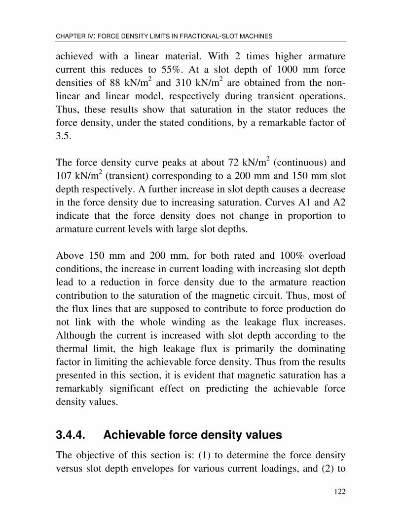
CHAPTER IV: FORCE DENSITY LIMITS IN FRACTIONAL-SLOT MACHINES
122
achieved with a linear material. With 2 times higher armaturecurrent this reduces to 55%. At a slot depth of 1000 mm forcedensities of 88 kN/m2 and 310 kN/m2 are obtained from the non-linear and linear model, respectively during transient operations.Thus, these results show that saturation in the stator reduces theforce density, under the stated conditions, by a remarkable factor of3.5.
The force density curve peaks at about 72 kN/m2 (continuous) and107 kN/m2 (transient) corresponding to a 200 mm and 150 mm slotdepth respectively. A further increase in slot depth causes a decreasein the force density due to increasing saturation. Curves A1 and A2indicate that the force density does not change in proportion toarmature current levels with large slot depths.
Above 150 mm and 200 mm, for both rated and 100% overloadconditions, the increase in current loading with increasing slot depthlead to a reduction in force density due to the armature reactioncontribution to the saturation of the magnetic circuit. Thus, most ofthe flux lines that are supposed to contribute to force production donot link with the whole winding as the leakage flux increases.Although the current is increased with slot depth according to thethermal limit, the high leakage flux is primarily the dominatingfactor in limiting the achievable force density. Thus from the resultspresented in this section, it is evident that magnetic saturation has aremarkably significant effect on predicting the achievable forcedensity values.
3.4.4. Achievable force density values
The objective of this section is: (1) to determine the force densityversus slot depth envelopes for various current loadings, and (2) to

123
investigate the behaviour of the optimum slot depth that maximizesthe force density at various current loadings. Figures 3.5 to 3.8 showthe force density against slot depth curves determined in the samemanner as in the preceding section, corresponding to the slot andmagnet dimensions of Tables 3.1 and 3.2 for both rotor types (SMRand IMR). To enable comparison of results, the slot current inTables 3.1 and 3.2 during continuous operating conditions areincreased by a fixed factor. The total slot current of curve X2 istwice the magnitude of that of curve X1 while X9 has a total slotcurrent 9 times that of X1. Some of the current levels are probablytoo high to be used even at transient state, due to thermal limits.
By examination of Figures 3.5-3.8, it is readily apparent that anoptimum slot depth, at which the force density is a maximum, existsfor each current loading. It is interesting to notice the changes in thegradient of the force density curves. The force density curvesinitially exhibit positive gradients, reach a maximum and thendecrease with a negative gradients. Also evident in the plot is thefact that, the negative gradient of the curves becomes steeper withincreasing slot current.
Examination of the curves indicate that, due to saturation effects, thedifference in distance between adjacent envelopes decrease;although the slot current is increased gradually up to a factor of 9(X9), the peak force density only increased by approximately three-fold in the SMR configuration. This factor decreases with thedecrease in the pole arc for the IMR configuration.
Figure 3.9 is obtained with the aid of Figure 3.5. It shows thevariation of slot depth at which the peak force density occurs, andthe peak force density values, with the current multiplication factor.It is interesting to note that at high values of current (higher than 3times the thermal rating), the peak force density occurs at

CHAPTER IV: FORCE DENSITY LIMITS IN FRACTIONAL-SLOT MACHINES
124
approximately the same slot depth of 100 mm. As stated above, atrated condition, (X1), a peak force density of approximately70 kN/m2 is achieved with a slot depth of 200 mm. However, with amultiplication factor between 3 and 9, a peak force density of 120kN/m2 and 190 kN/m2 is achieved with approximately the same slotdepth of 100 mm.
Figure 3.5: Force density versus slot depth for SMR machines.
0
30
60
90
120
150
180
210
0 200 400 600 800 1000Slot Depth (mm)
Forc
e D
ensi
ty (k
N/m
2)
X1 X2 X3 X4 X5 X6X7 X8 X9
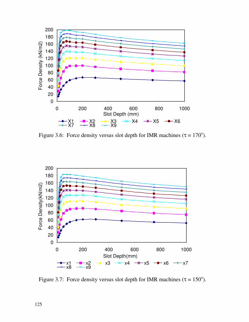
125
020406080
100120140160180200
0 200 400 600 800 1000Slot Depth (mm)
Forc
e D
ensi
ty (k
N/m
2)
X1 X2 X3 X4 X5 X6X7 X8 X9
Figure 3.6: Force density versus slot depth for IMR machines (τ = 170o).
020406080
100120140160180200
0 200 400 600 800 1000Slot Depth(mm)
Forc
e D
ensi
ty(k
N/m
2)
x1 x2 x3 x4 x5 x6 x7x8 x9
Figure 3.7: Force density versus slot depth for IMR machines (τ = 150o).

CHAPTER IV: FORCE DENSITY LIMITS IN FRACTIONAL-SLOT MACHINES
126
0
20
40
60
80
100
120
140
160
180
0 200 400 600 800 1000Slot Depth (mm)
Forc
e D
ensi
ty (k
N/m
2)
x1 x2 x3 x4 x5 x6 x7 x8 x9
Figure 3.8: Force density versus slot depth for IMR machines (τ = 120o).
40
60
80
100
120
140
160
180
200
220
0 1 2 3 4 5 6 7 8 9Current Factor
Pea
k Fo
rce
Den
sity
(kN
/m2)
& S
lot
Dep
th (m
m)
Peak Force Density Slot Depth
Figure 3.9: Averaged peak force density values andcorresponding slot depths versus current multiplication factor.
127
For continuous load operations, (X1), a force density no grater that72 kN/m2 can be achieved. For transient operation, within a one-minute time frame, current factor of 3, no greater than 120 kN/m2
can be achieved. At extreme transient operations (X9), for say onesecond, no greater that 205 kN/m2 can be achieved.
These results stresses the important fact that, in applicationsinvolving high slot currents and experience high armature reactioneffects, the use of deep slots yields no advantages. A smaller slotdepth would enhance the performance at high current levels, but willhave the opposite effect at low current levels. From figure 3.9, it isobvious that for any current loading greater or equal to 3 times therated condition of Table 3.1, a slot depth of approximately 100 mmshould not be exceeded.
When a machine is designed, one tends to concentrate on the peakand rated torque. Deep slots up to 200 mm would result in anacceptable peak force density during rated condition. However a 200mm slot depth would have an adverse effect on the achievable peakforce density during transient conditions. Therefore, the slot depthchosen would depend on the relative importance between thetransient and continuous torque for a particular application due tothe conflict between them.
Table 3.3, summarizes the approximate maximum force densityobtained from figure 3.5 to 3.8 with respect to the assumed currentloading for SMR and IMR machines.

CHAPTER IV: FORCE DENSITY LIMITS IN FRACTIONAL-SLOT MACHINES
128
Table 3.3: Summary of maximum force density values.
OperatingConditions
CurrentCondition
Peak ForceDensity(kN/m2)(SMR)
τ120
(IMR)
τ150
(IMR)
τ170
(IMR)Continuous IRated 70 53 62 67Peak 3IRated 120 92 92 100Extreme 8IRated 190 183 183 199
3.5. FORCE DENSITY VARIATION WITH WINDING CURRENT
DENSITY
The aims of this section are to investigate the force densitybehaviour for a range of slot depths with increasing current density(but keeping slot and tooth width constant) and to obtain forcedensity versus slot depth characteristics, for a range of windingcurrent densities, which can be used as a design tool.
In the first part of the investigation, simulations were performedonly for a fixed rotor position (the position shown in Figure 3.1)since the behaviour of the force density rather than actual values isof interest. This is sufficient to highlight the way the current loadingin each slot influence the force density. Thus as the slot depthincreased the stator and rotor dimensions listed in Table 3.4 wereheld constant with gradual increase in slot current density. The slotdepth was varied in steps from 20 to 300 mm. Simulation was onlyperformed for the SMR configuration as the same behaviour patternwould be expected with the IMR designs.

129
Table 3.4: Machine dimensions (in mm) for different slots depths
τp hm bS bd hS
200 20 33.33 33.33 Varied
Although some of the current density and slot depth combinationsmay not be used in practice, due to thermal limits and mechanicalconstraints, nonetheless, these are considered in the investigation inorder to facilitate the understanding of the saturation effects; theeffect of saturation on the force density will become more obvious atthese extremes.
Figure 3.10 shows the force density against current density forvarious slot depths for a pole pitch of 200 mm. It is evident that theforce density increases with current density. However the gradient ofthe curves becomes greater with increasing slot depth. Thus for afixed current density, a deeper slot would yield a higher forcedensity. For current density values greater than 3 A/mm2 the curveswith slot depths of 150, 200 and 300 mm tend to converge to thesame characteristic. Above 3 A/mm2 the force density achieved forall of the 3 slot depths are approximately the same for all currentdensity values. The three curves merge at a current density of 4A/mm2 corresponding to a force density of 88 kN/m2. Thus with acurrent density of 6 A/mm2 a force density of 100 kN/m2 can beachieved by using a slot depth of 100 mm just as well as 150, 200 or300 mm.

CHAPTER IV: FORCE DENSITY LIMITS IN FRACTIONAL-SLOT MACHINES
130
0
20
40
60
80
100
120
140
0 2 4 6 8 10
Current Density (A/mm2)
Forc
e D
ensi
ty (k
Nm
2)
150mm 100mm 75mm 50mm 200mm300mm 10mm 15mm 20mm 30mm
Figure 3.10: Force density versus current density characteristics.
Increasing winding current density by a factor of 2.5 to 10 A/mm2 inthese slots results in an increase in the force density by a factor ofonly 1.4 achieving 124 kN/m2. This factor increases approximatelyto 2.1 for slot depths of 75 mm and 50 mm. At very high currentdensity levels (outside the range shown in Figure 3.10) all curveswill eventually merge. The current density level at which this occurswill vary for each slot depths, with the 10 mm slot depth being thehighest.

131
0
50
100
150
200
250
0 50 100 150 200 250 300Slot Depth(mm)
Forc
e D
ensi
ty(k
N/m
2)
1 3 6 9 12 15 1821 24 27 30
REGION 2
REGION 1
Figure 3.11: Force density versus slot depth curves for various currentdensity values.
From the above discussion, two interesting regions having oppositecharacteristics can be seen to exist. In order to illustrate theseregions, the data of Figure 3.10 are represented in a slightly differentformat in Figure 3.11. It shows the force density variation with slotdepth for current densities up to 30 A/mm2. Region 1: For fixedcurrent densities, a greater force density is achieved with deeperslots. Region 2: For fixed current densities, equal force densities areachieved with shallow slots. In the linear region the effect of slotdepth is negligible and the force density increases directly with totalslot current. In the non-linear region, however, the saturation is dueto combination of total slot current and slot depth. It is seen that forcurrent densities of 3, 6 and 12 A/mm2, the slot depth above whichno further increase in force density with increased slot depth (andmachine size) is 150, 100 and 75 mm respectively.
CHAPTER IV: FORCE DENSITY LIMITS IN FRACTIONAL-SLOT MACHINES
132
Data as those of Figure 3.11 can be used as a guide for the machinedesigner. From such characteristics the maximum allowable slotdepth for a given current density can be determined. However in-order to utilise these curves for design purposes, the resultantaverage of the force density must be determined. Determining thesecurves for a range of pole-pitches, will enable one to produce auseful database, that can be used to establish if the specification canbe met within the given space. The force density versus slot depthcharacteristics for different values of winding current density, andfor a range of pole-pitches, are given in Appendix II. It can be seenthat the allowable slot depth above which no increase in forcedensity is observed increases with the pole pitch. For example, witha 3A/mm2 a maximum slot depth of 100 mm is viable with a polepitch of 41.7 mm. However a greater maximum slot depth of 150mm is permitted with a pole pitch of 109.05 mm.
3.6. FORCE DENSITY AND FLUX-LINKAGE
Flux-linkage versus current graphs are very useful in modelling thebehaviour of an electric machine seen from its terminals. Comparedto the equivalent circuit models, they represent a much more generalmodel since saturation effects, space and time harmonics can beincluded. The model has rotor position and current as inputs and hasflux-linkage and torque as its output. The advantages of the flux-linkage analysis may be summarised as follows:
• Allows a unified theory for investigating all different types ofelectric machines
• Includes all phenomena that influence the machine electrically• Can be used to calculate the torque (if the losses are dealt with
outside the model)• Allows time transient calculations

133
• Can be used for control design
The main disadvantages are:• It is a black-box model that gives less insight into the
mechanisms which are the base for the machine function• More complex to use for analysis than a circuit model• Is not so useful during machine design. More useful for
modelling and designing controller and the power electronicconverter for a given machine.
Staton et al [37] used the flux-linkage versus current diagrams toillustrate the difference between the torque production mechanismsin different machine types. It is therefore interesting to see in whatway they can explain the maximum force density that can beachieved in low speed PM machines. The flux-linkage versuscurrent diagram is now used to discuss the same phenomenainvestigated earlier in this chapter, namely, to determine theinfluence of slot depth variation on the loop area of the flux-linkageversus current diagram.
In order to obtain the data for the flux-linkage analysis the machinewhose dimensional details are given in Table 3.4 is selected. Theslot current is varied from –50kA to +50kA in steps of 1kA, for 11different rotor position from 0 to 180 electrical degrees. The sameevaluation is performed for three different slot depths and thecorresponding flux-linkage versus current characteristics areobtained, as shown in Figure 3.12 and 3.13. The diagrams representall possible combinations of current and rotor position with one flux-linkage curve for each rotor position. Here it is assumed that thephases are fed symmetrically. Without this assumption, threeelectrical terminals and three different flux linkage values for allcombinations of slot currents would be needed for each slot depth. Itshould be noted that, for motor operation, only some of the

CHAPTER IV: FORCE DENSITY LIMITS IN FRACTIONAL-SLOT MACHINES
134
combinations of flux-linkage and current are relevant. This isbecause the current has to vary as a function of rotor position in amanner that produces torque in an efficient way.
The electric energy fed into the machine during one electric cyclecan be expressed in terms of the internal voltage, U, and current, I,as follows:
dtIUWel ∫= (6)This can be recast in terms of the flux-linkage (ψ) as:
Ψ∫= dIWel . (7)
The RHS of Equation (7) represents the area enclosed by thetrajectory of the machine’s flux-linkage and current. If we neglectthe mechanical losses then the mechanical energy produced mustequal the electrical energy. For one electrical cycle we have:
elaverageWFp =.2τ (8)
from which the average force over one cycle can be obtained asfollows:
∫ Ψ== IdW
Fpp
el
average.
.21
.2 ττ (9)
The average force during continuous operation can be obtained fromFigures 3.12 and 3.13 noting that (from Table 3.1) for slot depths of30, 50, 100 and 200 mm the peak current has to be limited to about5, 7, 10 and 12 kA, respectively, for thermal reasons. Thus themaximum torque that can be produced during continuous operationwill correspond to the areas A, B and C in Figures 3.12 and 3.13.

135
These areas correspond to approximately 2800, 3500, 4000 and5500-Watt.sec/cycle, respectively. Thus the continuous torque doesnot increase linearly with slot depth.
If we assume that the machine, for a short time, can withstand twicethe value of the rated current, we can see that the transient torquewill correspond to areas D, E and F.
It is seen that the machine with 200 mm deep slots would notproduce higher transient torque than the one with 100 mm slots.With 50 mm slot depth, the force will however be lower than with100 mm.

CHAPTER IV: FORCE DENSITY LIMITS IN FRACTIONAL-SLOT MACHINES
136
-0.4
-0.3
-0.2
-0.1
0
0.1
0.2
0.3
0.4
-30 -25 -20 -15 -10 -5 0 5 10 15 20 25 30
Current (kA)
Flux
Lin
kage
(Vs)
0.1 20 40 60 80 100
120 140 160
a
e
d
c
b
g
f
h Surface A=Loop abcdSurface D=Loop efbcghda
-0.3
-0.2
-0.1
0
0.1
0.2
0.3
-30 -25 -20 -15 -10 -5 0 5 10 15 20 25 30
Current (kA)
Flux
Lin
kage
(Vs)
0 18 36 54 72 90108 126 144 162 180
a
e
d
c
bf
h
g
Surface A=Loop abcdSurface D=Loop efbcghda
Figure 3.12: Flux Linkage versus slot current at different rotor positions– Top: 30mm slot depth, bottom: 50 mm.

137
-0.3
-0.2
-0.1
0
0.1
0.2
0.3
-30 -25 -20 -15 -10 -5 0 5 10 15 20 25 30
Current (kA)
Flux
Lin
kage
(Vs)
0 18 36 54 72 90108 126 144 162 180
a
h
g
f
e
d
c
b
Surface B=Loop abcdSurface E=Loop efbcghda
-0.3
-0.2
-0.1
0
0.1
0.2
0.3
-30 -24 -18 -12 -6 0 6 12 18 24 30
Slot Current (kA)
Flux
Lin
kage
(Vs)
0 18 36 54 72 90108 126 144 162 180
a
f
e
d
c
b
g
hSurface C=Loop abcdSurface F=Loop efbcghda
Figure 3.13: Flux Linkage versus slot current at different rotor positions– Top: 100mm slot depth, bottom: 200 mm.

CHAPTER IV: FORCE DENSITY LIMITS IN FRACTIONAL-SLOT MACHINES
138
The force density increases with the stator current amplitude. Thusthe loop area of ψ-I characteristic is directly related to the forcedensity and it varies greatly with slot depth. From the plots ofFigures 3.12 and 3.13, it is obvious that a 200-mm slot depth yieldsa relatively thin loop with smaller enclosed area compared to that ofa 50-mm slot depth. While the force density and rated torqueincrease with current magnitude, the deeper the slot the lower willthe peak torque capability be. It decreases both because saturationmakes loop area smaller and also because the peak flux linkage isreduced with slot depth due to increased leakage. Obviously, for agiven application and stator cooling arrangements, there is a slotdepth at which the force density is a maximum, as indeed wasillustrated in the previous sections following a totally differenttreatment.
It may be noted the Ψ-I graphs presented here are very different thanthat presented in [37]. This is due to the deep slots and high currentsassumed here which lead to higher flux-linkage values. The Ψ-Igraphs in [37] are more applicable to normal low force densitymachines.
Figure 3.14 and 3.15 show the flux-linkage versus current densityfor slot depths of 30, 50, 100 and 200 mm. If we assume that atcontinuous and transient condition a slot current density of 10A/mm2 and 20 A/mm2 is accepted, it is evident from the plots thatthe smaller slot depth of 30 mm would be more suitable to produce ahigher force density.

139
-0.4
-0.3
-0.2
-0.1
0
0.1
0.2
0.3
0.4
-30 -20 -10 0 10 20 30
Current Density (A/mm2)
Flux
Lin
kage
(Vs)
0 18 36 54 72 90108 126 144 162 180
a
f
e
g
h
d
b
c
Figure 3.14: Flux Linkage versus current density at different rotorpositions. Slot depth: 30 mm (top) 50 mm (bottom).
-0.4
-0.3
-0.2
-0.1
0
0.1
0.2
0.3
0.4
-30 -20 -10 0 10 20 30
Current Density (A/mm2)
Flux
Lin
kage
(Vs)
0 18 36 54 72 90 108
126 144 160 180
e
a
g
f
d
c
b
h

CHAPTER IV: FORCE DENSITY LIMITS IN FRACTIONAL-SLOT MACHINES
140
-0.4
-0.3
-0.2
-0.1
0
0.1
0.2
0.3
0.4
-30 -20 -10 0 10 20 30
Current Density (A/mm2)
Flux
Lin
kage
(Vs)
0.1 20 40 60 80 100120 140 160 180 199.9
a
f
e
c
d
h
g
b
Figure 3.15: Flux Linkage versus current density at different rotorpositions. Slot depth: 100 mm (top) 200 mm (bottom).
3.7. APPLICATIONS
Although the objective of the work presented in this chapter isprimary to determine the approximate peak force density limits andthe way they generally vary with slot depth and current density, theapproximate force density values for four direct-drive applicationsare presented here in order to demonstrate the practical significanceof this research work.
The choice of slot depth depends on the relative importance ofmeeting continuous and transient operating conditions. Inapplications where high force densities and electric loading arerequired due to limited space and the short-term peak torquerequirements is of high importance, such as direct-drive in-wheel

141
traction motors, slot depths of no greater than 100 mm should beused to fulfil the peak torque requirement. On the other hand, inapplications where continuous operation is more important thantransient operation, such as wind generators, slot depth up to 200mm can be used. A slot depth greater than this value would notresult in an increase in the achievable peak force density as thiswould only lead to an increase in the converter kVA requirementdue to the greater inductance [5].
Table 3.5 categorises example applications according to the relativeimportance of peak and rated condition and summarises themaximum slot depth that can be used by the designer. The slotdepths ranges of the first three applications, in Table 3.5, aredetermined with respect to the typical hub size of the wheels. Thetraction in-wheel motors for wheelchair, golf carts and forklifttrucks, are mainly designed to meet the peak torque requirementinstead of the rated torque. The minimum peak force densityrequired in a wheelchair, golf cart and forklift truck motors would beapproximately 20 kN/m2, 18 kN/m2, 50 kN/m2, respectively. Thiswould enable the motor to be fitted into the hub of the wheels withinthe available space.
In wind generators, however, the continuous rated conditions are ofgreater importance. The force density would typically be 70 kN/m2
with a 150 mm slot depth (Figure 3.4 and 3.5). For a 1.5 MW windgenerator having a rated speed of 18 rev/min, transportation andmechanical considerations limit the diameter and active length toabout 4.2 and 1.5 m, respectively. With a rated torque ofapproximately 800 kNm, one would require a force density of,approximately, 50 kN/m2.
The peak force density required in each of the applications willincrease as the active axial stack length is reduced. The percentage

CHAPTER IV: FORCE DENSITY LIMITS IN FRACTIONAL-SLOT MACHINES
142
in which this reduction is permitted will be set by the thermal limits,as a greater electric loading will be essential in fulfilling the peaktorque requirement.
Table 3.5: Force density values and slot depth range for fourdirectly-driven machines
Application OperatingCondition
Slot DepthRange(mm)
RequiredForce
Density(kN/m2)
PossibleForce
Density(kN/m2)
Wheelchair Transient <35 20 30Golf-cart Transient <45 18 32ForkliftTruck
Transient <70 50 70
WindGenerators
Continuous <200 50 70

143
CHAPTER IV
FORCE DENSITY LIMITS IN FRACTIONAL-SLOT MACHINES
4.1. INTRODUCTION
The previous chapter considered the achievable force density inmachines of integral-slot designs. More specifically, a machinehaving one slot per pole per phase (q) was assumed. This is ofcourse fully justified in view of the large number of poles requiredin the low-speed in-wheel motors considered in this thesis. Machineswith a small whole number of slots per pole per phase, however,have appreciable high-order harmonic emfs induced in the armaturewinding. This is because the corresponding winding elements ofeach phase under different poles occupy similar positions withrespect to the pole flux; the emf harmonics of all groups of thewinding phase therefore add algebraically and their full magnitudecontributes to the resultant emf of the entire armature. If the windingis wound with a fractional number of slots per pole per phase (q),and has a sufficiently well selected fractional coefficient, theseparate elements of the winding belonging to a given phase wouldbe under different poles, in different positions relative to themagnetic field. The displacement of these elements relative to the

CHAPTER IV: FORCE DENSITY LIMITS IN FRACTIONAL-SLOT MACHINES
144
pole axis may be chosen so that the fundamental emf will be onlyslightly reduced but the higher-order harmonics will diminish.
In this chapter the force density limits are investigated for machinesutilising fractional-slot windings. This type of windings althoughhave been used in some specialised applications, such as electricclocks, for many years, it is uncommon in industrial applications. Abrief review of ac machine winding design, with some focus onfractional slot arrangements, is therefore presented first.
4.1.1. ARMATURE WINDING FOR AC MACHINES[1,2]
In a rotating electric machine, coils are so arranged that when onecoil-side is under the influence of a north pole, the other coil-side, ofthe same coil, is under the influence of a south pole, i.e. the coil spanis approximately one pole-pitch. The reason is obvious since in thisway, although the emf is outwards in one coil-side and inwards inthe other, the back-to-back connection causes the emfs to be additiveround the coil circuit. There are some advantages, as will beexplained later, in having chorded coils in which the coil-sides arenot exactly one pole-pitch apart. The coils are laid in successionround the armature periphery and are normally embedded in slotswhich, in general, may be open, semi-closed or closed. Newadhesives have permitted direct bonding of the coils onto a smoothiron core, leading to a slotless design.
The coils may be interconnected in a variety of ways and it is reallyin this that windings differ. There are two basic physical types ofarranging the coils, namely single-layer and double-layer windings.Figure 4.1 illustrates a single-layer arrangement in which the wholeof the slot is occupied by the side of one coil. Such a single layer

145
would either contains a number of turns insulated from each other orhave a copper section subdivided to reduce eddy-current losses. Tolimit the number of awkward bends in the end connections, single-layer coils are placed concentrically in small groups, which areinterlinked in such a way as to minimise both the space taken upoutside the slot in the end connections, and the number of differentcoil shapes. Single-layer coils lend themselves to the use of semi-closed or closed slots, the coils being preformed at one end, pushedthrough the slots and connected up at the free end during thewinding process.
Figure 4.1: Single-layer concentric coil.
In the double-layer winding one coil-side lies in the top half of theslot and the other side in the bottom half of another slotapproximately one pole-pitch away, as shown in Figure 4.2. Thedouble-layer winding gives greater flexibility in design because ofthe ease with which the coil pitch can be chosen. Open slots arefrequently used and the coils are laid in them one after the otherround the periphery. There are two ways of bending the front-endconnections of each coil; inwards yielding a lap winding, oroutwards to form a wave winding.
In a poly-phase ac winding, the ends of each phase are normallybrought out to the terminal box and any desired interconnections can
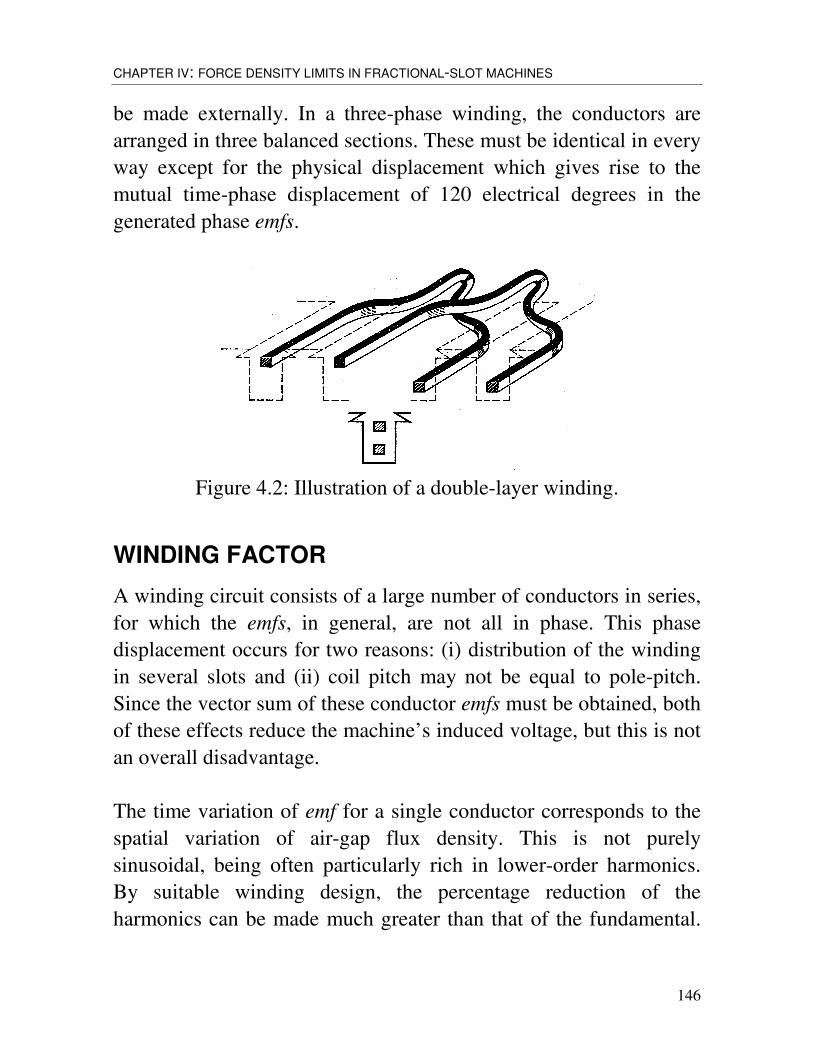
CHAPTER IV: FORCE DENSITY LIMITS IN FRACTIONAL-SLOT MACHINES
146
be made externally. In a three-phase winding, the conductors arearranged in three balanced sections. These must be identical in everyway except for the physical displacement which gives rise to themutual time-phase displacement of 120 electrical degrees in thegenerated phase emfs.
Figure 4.2: Illustration of a double-layer winding.
WINDING FACTOR
A winding circuit consists of a large number of conductors in series,for which the emfs, in general, are not all in phase. This phasedisplacement occurs for two reasons: (i) distribution of the windingin several slots and (ii) coil pitch may not be equal to pole-pitch.Since the vector sum of these conductor emfs must be obtained, bothof these effects reduce the machine’s induced voltage, but this is notan overall disadvantage.
The time variation of emf for a single conductor corresponds to thespatial variation of air-gap flux density. This is not purelysinusoidal, being often particularly rich in lower-order harmonics.By suitable winding design, the percentage reduction of theharmonics can be made much greater than that of the fundamental.

147
Consequently, the waveform of the circuit voltage approaches morenearly to a pure sine wave.The winding factors express mathematically the per unit reductionof the fundamental and each harmonic which takes place as a resultof distribution and chording. In practice the fundamental is rarelyreduced by as much as 10% whereas the harmonics are oftenreduced to negligible proportions. The same winding factors applyto the space distribution of mmf and so reduce the mmf spaceharmonics.
Distribution factor kd
Figure 4.3 shows the components and the resultant of the emfs dueto a phase group for a machine having 3 slots per pole per phase (q =3). Each component phasor is proportional to the rms value of thefundamental voltage for a slot conductor. It is displaced from theconductor voltage of a neighbouring slot by the slot angle, α,expressed in electrical degrees. The distribution factor is the ratio ofthe phasor sum to the arithmetic sum of the component emfs. Fromthe geometry of Figure 4.3 we get:
2/sin)2/(sin
2/sin2)2/(sin2
αα
αα
RqqR
kd =×
= (4.1)
Equation (4.1) gives the distribution factor for the fundamental emf.In case of harmonics, the distribution factor can be readily obtainedby noting that the pole-pitch of the nth harmonic is 1/n times that ofthe fundamental. Therefore, electrical angles based on the nth
harmonic would be n times those of the fundamental. Thus, thedistribution factor of the nth harmonic becomes:
)2/(sin)2/(sin
αα
nqnq
kdn = (4.2)

CHAPTER IV: FORCE DENSITY LIMITS IN FRACTIONAL-SLOT MACHINES
148
Figure 4.3: Distribution factor kd.
Coil pitch factor kc
If a coil is chorded, i.e. coil-pitch is not exactly equal to the pole-pitch, the emfs of two coil-sides will not be in phase and must beadded vectorially. The coils are usually short-pitched, i.e. the pitch isxπ electrical radians, being less than the full pitch by the chordingangle β, taken as 30o in Figure 4.4, while x is the per unit pitch.
Figure 4.4: Chording factor kp.
The coil pitch factor is defined as the ratio of the phasor sum of coil-sides emfs to their arithmetic sum. Therefore:

149
2sin
2)2/(sin2 ππ x
exe
k p == (4.3)
Whether the coil is under- or over-pitched by the electrical angle β,the pitch factor is still given by the sine of half the pitch angle. Thegeneral expression for the nth harmonic is:
2sin
πnxk pn = (4.4)
4.1.3. Fractional-Slot Windings
These are an advanced form of winding in which the number of slotsper pole per phase, q, is not an integer. If, for example we have q =5/2 (say, 30 slots, 3 phase and 4 poles), in practice, this would meanthat in one pole-pair the phase group (or coil-pitch) would bealternately 3 and 2 giving 5 slots per pole-pair per phase. In this casethe winding pattern will be repeated every two poles. If there hadbeen 27 slots instead of 30, q would have been equal to 9/4 and thepattern would have required four poles to complete. Thedenominator gives the number of poles required for a completepattern and the numerator determines the number of slots that eachphase takes up in this distance.
This type of winding permits the use of a standard lamination rangefor a wide variety of pole numbers. It is of course necessary for athree-phase balanced winding that the total number of slots isdivisible by 3, but it is no longer necessary that it should be divisibleby the number of poles as well. Another advantage is that the anglebetween the various conductor emfs is reduced. As it is shownabove, this in turn reduces the harmonic content of both emf andmmf waveforms.

CHAPTER IV: FORCE DENSITY LIMITS IN FRACTIONAL-SLOT MACHINES
150
End-turns do not contribute to the motor performance. Hence it isoften important to have their length minimised. Not only does thissave on space; but also minimising end turn length will minimisewire usage thus reducing motor cost. The winding configurationaffects the end turns length. The end turns are short when the coil-pitch is one or 2 slots. Anything above 2 requires considerableoverlapping of end connections. Table 4.1 shows the coil span orpitch for different slot and pole combination, the benefits offractional-slot winding are clearly demonstrated. It should be notedthat a coil span of one slot, although it requires q<1, it offers adistinct advantage as far as manufacturing cost is concerned.
This chapter deals with fractional-slot machines with q = 0.375, 0.50.75. The winding pattern spans 8, 2 and 4 poles, respectively, andthis is the minimum pole numbers that can be used in these cases.The acceptable number of poles must be an integer number of thesevalues. With q values of 0.375 and 0.5 the end windings cross fromone slot to the preceding slot over one tooth only while with qvalues of 0.75 the windings spans 2 slots. These combinations canbe automatically wound easily and are economical to make.
Table 4.1 Coil span for different slot/pole/phase values
Slot/pole/phase(q)
Coil spanin slot-pitches
WindingType
0.25 1 Fractional0.375 1 Fractional
0.5 1 Fractional0.75 2 Fractional
1 3 Integral1.25 3 Fractional1.5 4 Fractional

151
1.75 5 Fractional2 6 Integral
4.1. MODEL DESCRIPTION
The investigation presented in here follow pretty much the samesteps adopted in the previous chapter where integral-slot windingsare considered. As before, the investigation is limited to low-speedmachines where large number of poles will be required. However,here only the surface magnet rotor configuration is investigated. Themagnetic model shown in Figure 4.5 was developed in order toinvestigate the force density in fractional-slot machines. It is shownthe geometrical arrangement and typical field plots. Again, themodel assumes rectangular open slots and non-linear magnetisationcharacteristics are assumed for the core material.
4.2. CONTINUOUS AND TRANSIENT FORCE DENSITY
The pole pitch (τP), tooth width (bd), slot opening (bS) and magnetheight (hm), all vary with slot depth (hS). Model dimensions aregiven in Tables 4.2-4.4 for slot per pole per phase values of 0.375,0.5 and 0.75, respectively. In all cases, rotor magnets with aremanence of 1.25 T and coercive force of 90.5 kA/m are assumed.The winding current density values are, again, used as determinedby the thermal limitations [5], but allowing for the unique windingconfiguration in each case.
The slot currents are increased in steps by multiplying thecontinuous rated current by a factor varying between 1 and 9.
CHAPTER IV: FORCE DENSITY LIMITS IN FRACTIONAL-SLOT MACHINES
152
Figures 4.6-4.8 show the force density variation with slot depth fordifferent current multiplication factors.

153
a
b
c
Figure 4.5: Model of a fractional-slot machine,
(a) q = 0.5 (b) q = 0.75 (c) q=0.375

CHAPTER IV: FORCE DENSITY LIMITS IN FRACTIONAL-SLOT MACHINES
154
Table 4.2: Machine variables for different slot depths, q = 0.375.
hS, mm bS, mm bd, mm τP, mm hm, mm10 6,11 7,79 15.64 6,2615 6,22 8,42 16.46 6,5920 6,52 9,19 17.66 7,0730 7,15 10,67 20.06 8,0250 8,24 13,14 24.08 9,6275 9,29 15,60 27.98 11,20
100 10,12 17,64 31.24 12,49150 11,43 21,04 36.53 14,61200 12,47 23,88 40.91 16,36300 14,14 28,63 48.11 19,25500 16,66 36,14 59.40 23,76750 19,10 43,63 70.58 28,231000 21,16 49,99 80.06 32,02
Table 4.3: Machine variables for different slot depths, q = 0.5.hS, mm bS, mm bd, mm τP, mm hm, mm
10 6,11 7,79 20.85 6,2615 6,22 8,42 21.95 6,5920 6,52 9,19 23.55 7,0730 7,15 10,67 26.75 8,0250 8,24 13,14 32.1 9,6275 9,29 15,60 37.3 11,20
100 10,12 17,64 41.65 12,49150 11,43 21,04 48.7 14,61200 12,47 23,88 54.55 16,36300 14,14 28,63 64.15 19,25500 16,66 36,14 79.2 23,76750 19,10 43,63 94.1 28,231000 21,16 49,99 106.75 32,02

155
Table 4.4: Machine variables for different slot depths, q = 0.75.
hS, mm bS, mm bd, mm τP, mm hm, mm10 6,11 7,79 31.28 6,2615 6,22 8,42 32.93 6,5920 6,52 9,19 35.33 7,0730 7,15 10,67 40.13 8,0250 8,24 13,14 48.15 9,6275 9,29 15,60 55.95 11,20
100 10,12 17,64 62.48 12,49150 11,43 21,04 73.05 14,61200 12,47 23,88 81.83 16,36300 14,14 28,63 96.23 19,25500 16,66 36,14 118.80 23,76750 19,10 43,63 141.15 28,231000 21,16 49,99 160.13 32,02
As was observed with the integral-slot windings, it is seen that foreach current loading value there is an optimum slot depth at whichthe force density is a maximum. Again, the effect of saturation isdemonstrated here with the distance between successivecharacteristics decreasing as the current multiplication coefficient isincreased.
To enable comparison between fractional- and integral-slotwindings, Figure 3.5, which gives the force density for variouscurrent multiplication factor for q = 1, is reproduced here, forconvenience, as Figure 4.9.

CHAPTER IV: FORCE DENSITY LIMITS IN FRACTIONAL-SLOT MACHINES
156
Force Density Vs Slot Depth (q=0.375)
0
20
40
60
80
100
120
140
160
0 200 400 600 800 1000Slot Depth (mm)
Forc
e D
ensi
ty (k
N/m
2)
X1 X3 X4 X5 X6 X7 X8
Figure 4.6: Force density versus slot depth, q = 0.375.
Force Density Vs Slot Depth (q=0.5)
0
20
40
60
80
100
120
140
0 200 400 600 800 1000
Slot Depth (mm)
Forc
e D
ensi
ty (k
N/m
2)
X1 X2 X3 x4 x5 x6
Figure 4.7: Force density versus slot depth, q = 0.5.

157
Force Density Vs Slot Depth(q=0.75)
0
20
40
60
80
100
120
140
160
180
0 200 400 600 800 1000Slot Depth (mm)
Forc
e D
ensi
ty (k
N/m
2)
X1 X2 X3 X4 X5 X6 x7 x8
Figure 4.8: Force density versus slot depth, q = 0.75.
0
30
60
90
120
150
180
210
0 200 400 600 800 1000Slot Depth (mm)
Forc
e D
ensi
ty (k
N/m
2)
X1 X2 X3 X4 X5 X6X7 X8 X9
Figure 4.9: Force density versus slot depth, q = 1.

CHAPTER IV: FORCE DENSITY LIMITS IN FRACTIONAL-SLOT MACHINES
158
Figures 4.6-4.9 demonstrate that the force density values for afractional-slot winding are less than those of the integral-slotwinding. This is expected and is, of course, due to the reduction ofthe emf induced in the stator windings caused by lower values of thewinding factor. It is seen that the reduction in force density values isalmost independent of the current multiplication factor.
The winding factor for q = 0.5 is about 0.866 and it is seen that theforce density values for this case, Figure 4.7, are reduced, comparedwith Figure 4.9, by about the same factor (taking, for example, a slotdepth of 200 mm and current multiplication factor of unity, Figures4.9 and 4.7 give force density of about 65 kN/m2 compared with 55kN/m2, respectively). It should be noted that the winding factor of afull pitch winding having one slot per pole per phase is nearly unityand if an integer value of q greater than one were to be used, thepercentage reduction will be less. Of course, for a given air-gapdiameter, a longer stack will be needed to obtain the same torquevalue but the advantages offered by the simple winding constructionwith q = 0.5 would still make such a choice viable in someapplications.
Comparison of Figures 4.6 and 4.9 (q = 0.375 and 1, respectively)shows that significant reduction in the force density values occur insuch a fractional-slot winding (in the order of 25%). At the sametime, a value of q less than 0.5 offers only a marginal simplificationto the manufacturing process, namely smaller skew angle would berequired. Use of slot per pole per phase of less than 0.5 would leadto a substantially longer lamination stack to obtain the requiredtorque and force values and this more than offsets any advantages tobe gained.
159
With q = 0.75, it is seen (Figures 4.8 and 4.9) that the reduction ofthe force density values are about 7%. Such a fractional-slotwinding, although having coils spanning 2 slot pitches, still offersthe advantages of ease of winding and harmonic reduction.However, the winding is not as simple as that of a machine having q= 0.5 and the end connections are also longer.
It is the main conclusion of this section that slot per pole per phasevalues less than 0.5 should only be used when the applicationrequirement warrants this and can tolerate the increased stack length.In the development of the in-wheel motor for wheelchairapplication, which is described in the following chapter, q = 0.5 isused.
4.3. FORCE DENSITY VARIATION WITH WINDING
CURRENT DENSITY
The aim of this section is obtain force density versus slot depthcharacteristics, for a range of winding current densities, which canbe used as a design tool. In-order to be able to utilise these curvesfor design purposes, they must be produced in terms of the averageforce density values. Determining these curves for a range of pole-pitches, will enable one to produce a useful database, that can beused to determine if the specification can be meet within the givenspace. The force density versus slot depth characteristics fordifferent values of winding current density, and for a range of pole-pitches, are given in Appendix III for fractional-slot windingshaving slot per pole per phase values of 0.375, 0.5 and 0.75. Itshould be noted these curves are produced for the SMRconfiguration. Similar treatment can be followed to produce forcedensity characteristics for other rotor designs.

CHAPTER IV: FORCE DENSITY LIMITS IN FRACTIONAL-SLOT MACHINES
160
CHAPTER V
DESIGN AND EXPERIMENTAL EVALUATION
5.1. DESIGN SPECIFICATIONS
In this chapter three LPEV applications (a wheelchair, a golf cartand a forklift truck) are considered and brushless solutions arethought. The work concerning the wheelchair was carried out incollaboration with an industrial partner in the UK who provided thetechnical specifications and stipulated the practical design andmanufacturing constraints. It was the requirement of the industrialpartner that a geared, brushless, solution be identified, to enablecomparison with the in-wheel one, for their commercial decisionmaking purposes. Such a solution was indeed identified. It is notdescribed in this thesis as it lies outside its main theme. The authorwould be prepared to provide commercially unclassified informationregarding the geared solution to interested parties. The design targetsfor both the in-wheel and geared motors for wheelchair applicationsare given in Table 5.1.
The specification and design targets for the forklift truck areobtained from a Swedish manufacturer. The specifications used inthe work presented below are believed to represent developmentideas rather than an existing, geared, product. The industrial

161
specifications assumed a dc link voltage value of 24V. Thesespecifications are given in Table 5.2. However, the investigationconsidered the case of doubling the assumed dc link voltage, to 48V, in order to demonstrate the advantages of increasing systemvoltage.
Table 5.1: Design specifications for a wheelchair drive.
Direct-Drive GearedDC supply voltage, V 24 24Controller peak current limit, A 65 35Short term torque rating (1-min, 1/2 speed) 65 Nm 1.82 Nm
(a) Short term rated output power, W 510 285Continuous rated speed, rev/min 150 3000Continuous rated power, W 285 150Ambient temperature range, °C -25 to 50 -25 to 50Insulation class Class F Class F
Table 5.2: Design specifications for a forklift truck.
Direct-DriveDC supply voltage, V 24 48Controller peak current limit, A 300 300Short term torque rating 445 Nm 445 NmShort term rated output power, kW 3.2 3.2Continuous rated speed, rev/min 258 258Continuous rated power, W 595 595Ambient temperature range, °C -25 to 50 -25 to 50Insulation class Class F Class F

CHAPTER IV: FORCE DENSITY LIMITS IN FRACTIONAL-SLOT MACHINES
162
Table 5.3: Design specifications for a golf cart.
Direct-Drive GearedDC supply voltage, V 48 48Controller peak current limit, A 65 35Short term torque rating (1-min, 1/2 speed) 65 Nm 1.82 NmShort term rated output power, W 1000 571Continuous rated speed, rev/min 300 6000Continuous rated power, W 570 300Ambient temperature range, °C -25 to 50 -25 to 50Insulation class Class F Class F
The golf cart specifications, as per Table 5.3, are derived by theauthor utilising catalogue information of a number of manufacturers.The system voltage of the majority of normal duty golf carts is 48 V.
For the wheelchair in-wheel motor, a large constant torque isrequired at low speeds, from zero to 75 rev/min. From 75 rev/min upto the maximum speed, a constant power control is required. Thepeak torque in the constant range is 65 Nm and the maximum speedis approximately 250 rev/min. The motor must be designed to fitwithin the hub of an existing wheel having an outside diameter of 12inches (305 mm); as was stipulated by industry. The wheel speedmust be limited to 250 rev/min. For the geared motor, a constanttorque of 1.82 Nm is required from zero to 1500 rev/min. From 1500rev/min to 3000 rev/min, a constant power control is required. Thewheelchair and the golf cart have similar peak torque requirementswith the later requiring a larger speed range. This can be achievedwith a system voltage of 48 V.
The hub of the wheel of the forklift truck was fixed, by industry, at280 mm. This size is comparable to an in-wheel motor of a powerelectric wheelchair having a peak torque requirement of only 65

163
Nm. However, the peak torque requirement in the forklift truck, at445 Nm, is approximately comparable with the requirements of anelectric passengers vehicle having an outer diameter of, say, 340mm. The losses in a motor producing such a high peak torque arevery large (compared to the wheelchair motor) and additionalcooling features would be required. Thus the forklift truck motorsare designed with respect to their peak torque requirement instead oftheir thermal capacity, as limited information on the drive cycle isavailable. If the drive cycle was available, the intermittence could beknown and a comparison between the thermal time constant anddrive cycle could be made for each motor designed. Hence themotors could be sized according to their thermal demands instead oftheir peak torque tailoring the optimisation process towards a finaldesign of reduced volume. Much of the design work presentedbelow is directed at achieving a high efficiency motor with lowtorque ripple, keeping in mind the cost factor, size constraints anddemands made on the motor.
5.2. DESIGN CONSIDERATIONS
Lamination and winding design are the main factors that influencethe ability to automatically and economically assemble a stator.They must be considered at the design stage in order to minimise thestator assembly cost. The wire size, number of turns, windingconfiguration and pole-slot combination all affect the ease, orotherwise, of building the stator. The lamination itself cannot bealtered without paying large penalty in modification to tooling.Unlike, the lamination design, winding specification can be changedwithout major penalty. The following describes some designfeatures that has to be considered to enable realisation of anoptimised and economically manufactureable design.

CHAPTER IV: FORCE DENSITY LIMITS IN FRACTIONAL-SLOT MACHINES
164
5.2.1. STATOR LAMINATION
Since the laminations are cut from stripped material the diameter ofthe lamination will be important from the material savingsstandpoint. This must be considered when direct drive machines areused due to the greater machine size.
It is always desirable to have large slot opening for simplicity ofmanufacture. However a larger slot opening will result in low motorperformance and increase in audible noise. Usually the slot openingselected should be a compromise between the design requirementsand manufacturing process. The slot opening should be set no lessthan 2 mm. Also it was recommended, by industry, that the slotopening should be set to 0.5 to 0.7 mm greater than the wirethickness which will, obviously, vary depending on the motor size.The tang angle should be kept as small as possible. A maximumlimit of 30 degrees was set. This is important as the toothdimensions directly affects the injection blade design.
5.2.2. SLOT SHAPE
It is usually desirable to have deep, narrow slots. This ratio of slotdepth to width would be typically about 4. In applications wherespace is limited this factor must be optimised to obtain the highestpossible force density, as was illustrated in the previous twochapters.
Generally there are 2 types of slot configuration, the round andsquare bottom. The round bottom slots are the preferred shape asduring insertion process the wire has the tendency to fill the back ofthe slot and roll into the corners; thereby yielding a good fill factor.

165
The probability of this occurring in the square bottom slot is low, asthe winding tend to stay at the back of the slot.
5.2.3. STATOR WINDING
Winding specifications, such as wire size, turns and number ofstrands are important for automatic stator processing. Unlikelamination, wire sizes and the number of turns can be varied to acertain level without affecting drastically the machine performance.Generally there are two basic types of winding configuration:concentric and lap windings. The concentric type winding is usuallypreferred, as lap windings cannot be automatically inserted into theslots.
5.2.4. ROTOR DESIGN
The choice of pole numbers depends on many factors such as inertia,torque, cogging torque and speed. With high pole numbers itbecomes possible to use a one coil per group, short-pitched, windingwhich can eliminate the overlap of the end turns. The greater thepole number the smaller becomes the size of the machine.
The effect of increased flux by using magnet overhang can be quitesignificant on a short-stack motor.
5.3. THE WHEELCHAIR MOTOR
In order for the electric motor to be suitable for use in a direct-drivesystem, it must have a relatively low mass, high torque to mass ratio,low cost and operate at a reasonably high efficiency in order tomaximise vehicle range. A drop in motor efficiency increases thecurrent drawn from the battery and decreases its life and efficiency.The motor should have physical dimensions that are amenable to

CHAPTER IV: FORCE DENSITY LIMITS IN FRACTIONAL-SLOT MACHINES
166
location in the drive wheel. Slotted stators in brushless motor causecogging which adversely affects motor performance especially whenthe motor is directly coupled to the load. Cogging contributes toefficiency loss, motor and load vibration, and noise. Cogging also isa component of torque ripple, which prevents smooth motoroperation especially at low speeds. Thus cogging torque should bereduced to an acceptable level for smooth operation.
Another requirement of the design described here is that the phaseinductance must be kept as low as possible to allow the use of anexisting brushless motor controller forming part of the industrialpartner’s range of system modules. The controller is optimised fortrapezoidal back emf windings and it may be programmed to operatewith wide range of 3-phase BLDC motors and wheelchairconfiguration.
In deciding whether to opt for a sinusoidal or a trapezoidal typemotor, compatibility with the existing controller was a prime factor.This is designed for constant current (squarewave) operation and theBLDC design was hence adopted.
The approach followed in arriving at designs that meet thespecifications is to utilise established design rules to obtain apreliminary design, utilise a circuit based CAD, time-steppingsimulation program (which has in-built databases for typical anduser-defined magnet and steel materials) to examine and improvethe design, including parameters of the power-electronic converterand control, and then employ the finite element method to fine-tunethe magnetic circuit. Such CAD and FE packages are of coursecalculating, rather than design, tools. Hence they improve theproductivity of the design engineer enabling evaluation of
167
alternative designs efficiently, but can make no judgement and thisis still the designer’s task!
5.3.1. NUMBER OF POLES
In the initial stage of the design process, the pole numbers werevaried keeping the outside diameter and air-gap diameter constant at200 mm and 184 mm, respectively, as this is determined by thewheel size, and choosing sintered NdFeB as the magnet material.Design calculations assumed an operating temperature of 100oC.
Table 5.4 summaries some of the designs studied. It shows that thereis a small improvement in overall performance as the pole number isreduced from 36 to 28 due to the reduction in stator iron losses, butany further reduction yields inferior performance manifested in areduction in peak torque. This is due to the increasing size of the endwindings and flux return paths.

CHAPTER IV: FORCE DENSITY LIMITS IN FRACTIONAL-SLOT MACHINES
168
Table 5.4: Effect of number of poles on motor performance.
Design numberD1
D2 D3 D4 D5
Number of poles 36 32 30 28 26Slots 42 48 45 42 39Coil span 1 1 1 1 1Packing factor 0.273 0.236 0.239 0.256 0.257Pole arc 180 180 180 180 180Stack length, mm 57 62 70 80 80Slot depth, mm 25 20 25 20 23Tooth width, mm 4.5 5 5 5 5.8Turns/coil 4 4 4 4 4Wire diameter, mm 1.5 1.12 1.3 1.3 1.4Strands 2 3 3 3 3Back iron depth, mm 4 5 4 5 5Copper weight, kg 0.894 0.724 1.018 1.075 1.174Iron weight, kg 6.23 7.36 9.44 9.29 9.08Efficiency, % 83.4 82.6 83.4 84.5 86Peak torque, Nm 76.5 73.7 75.61 77.92 75
5.3.2. PROTOTYPE DESIGN
Having established that 28 poles yield the most balanced design,design D4, Table 5.4, was subjected to further modifications. It wasnecessary, for mechanical reasons, to redesign assuming an outsidediameter of 190 mm, compared to 200 mm in design D4. A finiteelement field plot, shown in Figure 5.1, confirms that is achievablewhile the flux density values everywhere in the magnetic circuitremaining below saturation levels. Furthermore, a smaller wirediameter was chosen, for manufacturing reasons, and an appropriateincrease in the number of turns per coil was made. Table 5.5 givesthe details of the experimental in-wheel motor.
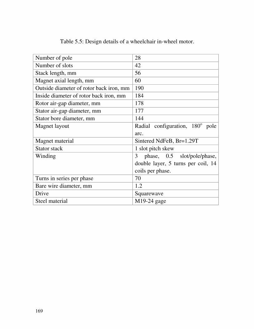
169
Table 5.5: Design details of a wheelchair in-wheel motor.
Number of pole 28Number of slots 42Stack length, mm 56Magnet axial length, mm 60Outside diameter of rotor back iron, mm 190Inside diameter of rotor back iron, mm 184Rotor air-gap diameter, mm 178Stator air-gap diameter, mm 177Stator bore diameter, mm 144Magnet layout Radial configuration, 180o pole
arc.Magnet material Sintered NdFeB, Br=1.29TStator stack 1 slot pitch skewWinding 3 phase, 0.5 slot/pole/phase,
double layer, 5 turns per coil, 14coils per phase.
Turns in series per phase 70Bare wire diameter, mm 1.2Drive SquarewaveSteel material M19-24 gage

CHAPTER IV: FORCE DENSITY LIMITS IN FRACTIONAL-SLOT MACHINES
170
Figure 5.1: Field plot and flux density values (top right) – wheelchair motor.
The motor’s main components are the stator and rotor assembliesand the position sensing arrangements. These are now described indetails.
Stator Assembly
The 42 equally spaced, slotted stator in which the 3-phase windingsthat generates the electromagnetic field are lodged, is constructedusing high quality silicon-iron steel lamination sheets to reduce thecore losses that increases rapidly at high flux densities. The statorlaminations were spark eroded from the material M19-24, 0.56 mm.Each individual lamination is covered with an insulating varnish andlaminations were arranged into a vertical stack, pressed and thenfused to form the solid uniform 56 mm core shown in Figure 5.2.

171
Figure 5.2: Stator core and bearing.
The 42 stator teeth have a circumference tooth width of 6 mm, atooth height from the root to the tip of 28 mm and a 3-mm thicktooth tip. The circumference slot opening between adjacent teeth is 3mm with each tooth having a tang angle of 30°. The stator yokethickness is 18.5 mm and the available shaft space is 84 mmdiameter to enable sufficient space to mount the stator-mountingboss.
To ensure the performance of the motor at high torque, the toothwidth and back iron depth were made sufficiently large to ensurethat the quasient flux density was somewhat below saturation levelto allow armature reaction flux to flow without distortion of the backemf waveform and risking excessive reductions in torque perampere.

CHAPTER IV: FORCE DENSITY LIMITS IN FRACTIONAL-SLOT MACHINES
172
A stator-mounting boss, shown in Figure 5.3, was milled from analuminium block and is used to clamp the steel lamination sheets inplace. With reference to Figure 5.3, when the screws in the stator-mounting boss are tightened the steel lamination sheets will betightly clamped. When screws are released the stator laminationstack can be skewed to any angle desired. This arrangement enabledchanging of the skew angle during development. Of course, themounting boss was not used in the pre-production prototype whereskewed laminations were fused together. The wheelchair shaft is25 mm in diameter. Two keys are machined into the shaft. An axialgroove keyway is machined into the inner surface of both stator-mounting bosses. During assembly both keys on the shaft lodge intothe keyway creating a rigid lock.
Figure 5.3: Mounting boss.

173
The winding was arranged so that each slot carries 10 conductors,1.2 mm thick in diameter insulated to class F. There are 3 strandsper conductor and 5 turns per coil, 14 coils per phase, (i.e. 28 coil-sides per phase), and 70 turns in series per phase. Each coil has amean turn length of 141 mm. The winding arrangement is of thedouble-layer, fractional slot, concentric, bobbin type. The motor has1.5 slot/pole i.e. 0.5 slot per pole per phase. Hence the bobbinwinding used has a span of 1 slot-pitch or 120 electrical degrees.This results in a compact design with no bulky end windings causedby overlapping. The assembly process is simplified and the windinginsertion in the slot is less tedious. The total area occupied by thewindings in the slot is 32.8 mm2. The slot area for the final designwas 120 mm2. Thus the fill factor was approximately 35%. Althougha larger fill factor could be obtained, during the design stage a fillfactor of 35% was a realistic figure. A greater fill factor is possibleand a machine of higher efficiency can be obtained for the samecurrent. The winding factor is 0.716. A slot linear of 0.20 mmthickness was used to insulate the windings from the slot walls.
Rotor Construction
The outer rotor is provided with 28 magnet segments. The magnetswere delivered machined to their final shape. Each pole segment is3 mm in radial thickness and is made up of 2 blocks of 30 mmarranged axially resulting in an overall axial length of 60 mm, takinginto account the 2 mm magnet overhang at each end of the rotor.Due to the large outer diameter the magnets were approximatelysquare shaped. The magnet segments are epoxyed to the innersurface of a 190 mm diameter, mild steel rotor tube of 70 mmoverall axial length, to keep the rotor poles in place. The steel tubethat acts as a rotor yoke (return path completing the magneticcircuit) has a radial thickness of 3 mm. Figure 5.4 shows the rotorcasting and end cover.
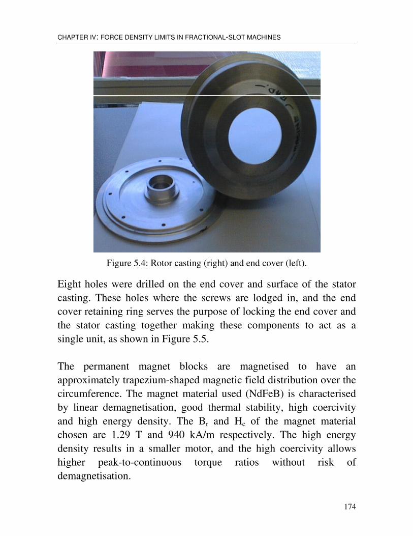
CHAPTER IV: FORCE DENSITY LIMITS IN FRACTIONAL-SLOT MACHINES
174
Figure 5.4: Rotor casting (right) and end cover (left).
Eight holes were drilled on the end cover and surface of the statorcasting. These holes where the screws are lodged in, and the endcover retaining ring serves the purpose of locking the end cover andthe stator casting together making these components to act as asingle unit, as shown in Figure 5.5.
The permanent magnet blocks are magnetised to have anapproximately trapezium-shaped magnetic field distribution over thecircumference. The magnet material used (NdFeB) is characterisedby linear demagnetisation, good thermal stability, high coercivityand high energy density. The Br and Hc of the magnet materialchosen are 1.29 T and 940 kA/m respectively. The high energydensity results in a smaller motor, and the high coercivity allowshigher peak-to-continuous torque ratios without risk ofdemagnetisation.
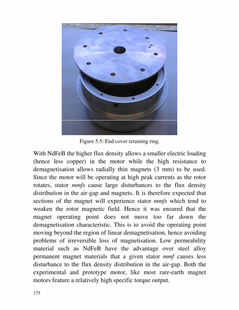
175
Figure 5.5: End cover retaining ring.
With NdFeB the higher flux density allows a smaller electric loading(hence less copper) in the motor while the high resistance todemagnetisation allows radially thin magnets (3 mm) to be used.Since the motor will be operating at high peak currents as the rotorrotates, stator mmfs cause large disturbances to the flux densitydistribution in the air-gap and magnets. It is therefore expected thatsections of the magnet will experience stator mmfs which tend toweaken the rotor magnetic field. Hence it was ensured that themagnet operating point does not move too far down thedemagnetisation characteristic. This is to avoid the operating pointmoving beyond the region of linear demagnetisation, hence avoidingproblems of irreversible loss of magnetisation. Low permeabilitymaterial such as NdFeB have the advantage over steel alloypermanent magnet materials that a given stator mmf causes lessdisturbance to the flux density distribution in the air-gap. Both theexperimental and prototype motor, like most rare-earth magnetmotors feature a relatively high specific torque output.

CHAPTER IV: FORCE DENSITY LIMITS IN FRACTIONAL-SLOT MACHINES
176
Position sensing
Initially the sensing system was based on a 28-pole magnet disc and3 hall sensors. During preliminary tests it was observed that themotor’s trapezoidal back emf waveform could not be brought intosimultaneous alignment with the sensor signals. This resulted insignificant mismatches between the controller output signals and themotor current requirements. It was discovered that the problem wascaused by the sizes of successive poles on the 28-pole magnet discbeing distinctly non-uniform. After due consideration it was decidedto replace the sensor system by a one based on a specially developedtoothed aluminium disc and 3 optical sensors. This proved to besatisfactory. The sensors are placed 8.57° (mechanical) or 120°(electrical) apart, as shown in Figure 5.6. A 14 equally spacedslotted aluminium disc mounted on the rotating shaft is used tobreak the light beam. The sensors are operated at a reduced voltageof 5V to provide long life capability.
Figure 5.6: Rotor position sensing arrangement.
177
Effect of Skewing
Cogging torques are produced by the circumferential component ofattractive forces between the magnet and the stator teeth (alignmentbetween successive stator teeth and individual magnets). Coggingtorque, even when non-integral values of slots per pole per phase areemployed, can be high and is practically unacceptable in direct-drivelow-speed motors where smoothness is important. It is independentof the phase current and so can become dominant at low torquesvalues. It can be minimised through choice of slot number, toothwidth, pole number, and pole width combination that minimises thenumber of stator-rotor edges that can simultaneously align as therotor revolves. Skewing also helps here and, as with conventionalmachines, a typical skew is one stator slot-pitch. Either the stator orthe rotor can be skewed. If the stator is skewed, the insertion of thewinding will then be a little more difficult. The alternative is to skewthe rotor magnet excitation system but this is difficult and was notjustified at the development stage, so stator skew was used.
A disadvantage of low number of slots/pole/phase employed is thatone slot stator pitch corresponds to a large electrical angle of 120degrees, giving a winding factor of 0.716. The resulting reduction inemf per speed and torque per ampere caused by the skew is thereforesignificant, so the impact on the cogging torque of differing levels ofskew was investigated during construction prior to winding. Figure5.7 shows the predicted cogging torque versus rotor position forvarious skew angles. The lowest cogging torque is achieved with askew angle of 1 slot and this was used in the experimental motor.However, if we assume that 3% cogging torque is acceptable a skewangle of half a slot-pitch would be sufficient. This will enhance themachine’s capability and a shorter axial stack length will be requiredto produce the same output torque. Indeed, the pre-productionprototype employed a stator skewed by only half a slot-pitch.

CHAPTER IV: FORCE DENSITY LIMITS IN FRACTIONAL-SLOT MACHINES
178
-0.100
-0.050
0.000
0.050
0.100
0.150
0 10 20 30 40 50 60
Rotor Position (electrical degrees)
Cog
ging
torq
ue (N
m)
Skew 1 Skew 0.5
Figure 5.7: Cogging torque characteristics.
5.3.3. TESTING
The experimental machine described above was built and subjectedto a series of laboratory and field test. Figure 5.8 shows the in-wheelmotor fitted to a wheelchair. The laboratory tests were limited tocogging torque measurement and performance evaluation.
The cogging torque characteristic was determined experimentally bydisplacing the stator and measuring the induced torque. The statorwas rotated, via a flexible coupling and a torque sensor, by a rotarytable mounted so that its axis was collinear with the stator. Ofcourse, stator excitation was absent throughout this test. The rotarytable was driven by a stepper motor via a worm-wheel gearbox. Theresolution of the stepper motor was 200 steps per revolution and thegearbox had a speed ratio of 90:1. The estimated backlash in thegearbox was less than 0.1 degrees.
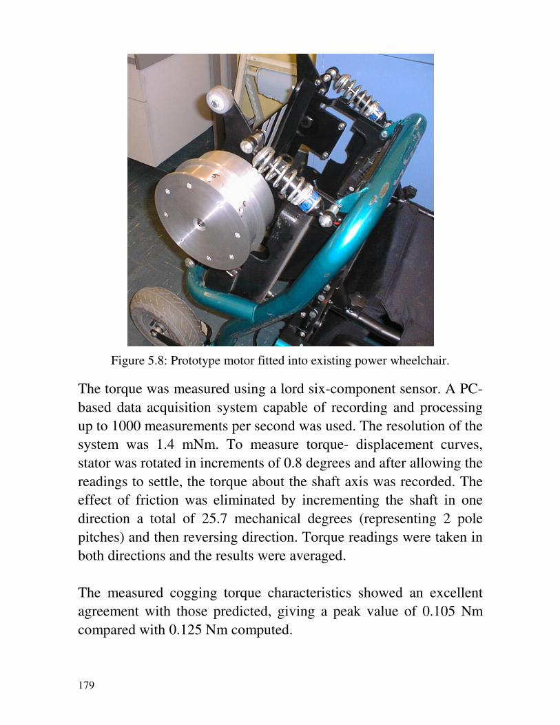
179
Figure 5.8: Prototype motor fitted into existing power wheelchair.
The torque was measured using a lord six-component sensor. A PC-based data acquisition system capable of recording and processingup to 1000 measurements per second was used. The resolution of thesystem was 1.4 mNm. To measure torque- displacement curves,stator was rotated in increments of 0.8 degrees and after allowing thereadings to settle, the torque about the shaft axis was recorded. Theeffect of friction was eliminated by incrementing the shaft in onedirection a total of 25.7 mechanical degrees (representing 2 polepitches) and then reversing direction. Torque readings were taken inboth directions and the results were averaged.
The measured cogging torque characteristics showed an excellentagreement with those predicted, giving a peak value of 0.105 Nmcompared with 0.125 Nm computed.

CHAPTER IV: FORCE DENSITY LIMITS IN FRACTIONAL-SLOT MACHINES
180
The experimental motor was tested initially with the current limit setso high that the maximum capability of the experimental motorcould be determined. Of course, in normal operation the currentlimit will be set at such a value that no damage can occur to bothmotor and controller. Thus Figure 5.9 shows the maximumcapability of the motor.
During testing, the motor was fed from a square-wave controller andmechanical load was applied to the outer rotor via a frictionmechanism attached to a pre-calibrated spring balance whichrecorded the braking force. The speed was recorded via an opticaltachometer. Since both voltage and current are non-sinusoidal, theinput power to the motor was obtained with the aid of a poweranalyser.
It is seen, Figure 5.9, that at a rated speed of 150 rev/min the shaftpower is approximately 600 W, and the corresponding torque isabout 42 Nm. Of course, for the wheelchair only requires 285 W(17.8 Nm) at rated speed. However if the machine was set to itsrequired operating conditions we would get power to weigh ratio of41W/kg. Power-to-weight figures for low speed machines motorsare inherently low. At the half speed point of 75 rev/min, themachine is capable of delivering approximately 68 Nm with anefficiency of 55%.
It should be noted that two identical experimental machines werefitted to the back wheels of a wheelchair and tested according tosome random duty cycle. The industrial partners were completelysatisfied with the performance and work started immediatelyafterwards on pre-production prototypes. The author was not grantedpermission to include details of field testing of experimental motorsor prototype testing in this thesis.

181
0
100
200
300
400
500
600
700
800
0 10 20 30 40 50 60 70
Torque (Nm)
Spe
ed(r
pm)/P
ower
Out
put
(Wat
t)
0
10
20
30
40
50
60
70
80
90
Cur
rent
(Am
ps)/
Effi
cenc
y (%
)
Power Speed Efficiency Current
Figure 5.9: Performance characteristics of experimental wheelchair motor.
5.4. FORKLIFT TRUCK MOTORS
The speed-torque requirement as with provided by a Swedishforklift manufacturer are given in Table 5.6. The system voltage wasspecified at 24 V dc.
Table 5.6: Drive requirements of a 24 V forklift truck.
Speed(Rev/min)
Torque (Nm)
Peak Acceleration 68 445At max gradient 80 290At max weight 237 62
Maximum speed 258 22Again, in deriving a solution, established design roles are used toobtain preliminary dimensions and winding details, a circuit basedsimulation program enables examination and improvement of

CHAPTER IV: FORCE DENSITY LIMITS IN FRACTIONAL-SLOT MACHINES
182
preliminary electromagnetic design and the power-electronicconverter and control strategy, and finally the finite element methodis employed to fine-tune the magnetic circuit. After a number ofiterations an electromagnetic design whose details are given in Table5.7 was identified.
Table 5.7: Data of forklift truck motor, Design D1. (b) Rotor outsidediameter, mm 280
Rotor Yoke, mm 8Magnet radial thickness, mm 5Pole arc of magnet, elec. deg. 140Poles 16Air-gap radius, mm 127Air-gap radial length, mm 1Tooth tip radius, mm 126Slots 24Tooth width, mm 13.5Slot depth, mm 60Stator yoke thickness, mm 16Stator bore radius, mm 50Axial stack length, mm 200Total coils 24Turns per Coil 4Number of Strands 14Bare wire diameter, mm 1.5Total conductors 192Turns in series per phase 32Layers 2Mean turn length, mm 470Conductor area, mm2 24.74Slot area, mm2 637Slot fill factor 0.31

183
The design assumes a fractional-slot, double-layer, star-connectedwinding design with 0.5 slot per pole per phase. Such a windinglayout will result in a short stator end winding with no crossoversand is much easier to wind using existing induction motor winders.The reduction in end-winding length will reduce the copper lossduring peak torque operation considerably and thus limit thetemperature rise of the winding and magnets. The stator has 24 coilsconsisting of 4 turns each. A bare wire of 1.5 mm in diameter is usedas any greater would be much harder to wind.
The external rotor utilises 16 magnet blocks radially magnetized andthe windings are placed in the 24 parallel stator slots. It can be seenthat, as the rotor rotates only 1.5 poles align with the tooth edges atevery instant. This will reduce the cogging torque compared with anintegral-slot design. After various design tradeoffs the peak currentin the motor windings was set at 300 A. Such a high currentnecessitates the use of 14 strands. The conductor area thus isapproximately 25 mm2. The minimum rms current density achievedwas 8.5 mm2.
Figure 5.10 shows the flux density plot corresponding to maximumcurrent operation. It is seen that the motor is designed very close tosaturation with a peak tooth flux density of 1.9 T. The dc fluxdensity in the rotor yoke was limited to approximately 2.0 T. Figure5.11 gives the air-gap flux density waveform obtained at its centre.
Examination of the torque-speed characteristics predicted for thisdesign, Figure 5.12, reveals that the constant torque range, in theabsence of controller phase advance angle, is very limited indeed.The characteristic exhibits approximately constant torque of 520 Nmfrom 0 to 68 rev/min. It is seen that above the base speed 68 rev/minthe torque decreases rapidly. Therefore, the torque requirements at80, 237 and 258 rev/min, shown in Table 5.6 could not be fulfilled.

CHAPTER IV: FORCE DENSITY LIMITS IN FRACTIONAL-SLOT MACHINES
184
Figure 5.10: Forklift truck motor flux plot.
-1
-0,75
-0,5
-0,25
0
0,25
0,5
0,75
1
0 10 20 30 40 50 60 70 80 90
Figure 5.11: Air-gap flux density waveform.

185
0
50
100
150
200
250
300
350
400
450
500
550
0 25 50 75 100 125 150 175 200 225 250 275 300 325
Speed (rpm)
Torq
ue (N
m)
Torque(25C) Torque(25C-45A)
Figure 5.12: Torque-speed characteristics with 0 and 45o advance angle,Design D1.
Hence to extend the torque-speed envelope, various phase-advanceswitching angles were examined. It was found that a phase advanceangle of 45 degrees was sufficient to meet the requirements over thefull speed range specified. Indeed, with such a phase advance angledesign D1 exceeds the requirements and, therefore, can be furtherimproved.
In an attempt to improve the first design (D1), the maximumwinding current density was reduced to 7.5 mm2. This was affectedby setting the peak current limit to 260A leading to the seconddesign (D2). Such an assumption enables meeting both the peak andmaximum gradient torque requirements of 445 Nm, Table 5.6. Aphase advance angle of 45o yields 60 and 30 Nm at speeds of 237and 258, respectively. Therefore, the torque requirement, over thespecified speed range, was still met with this current limit.
CHAPTER IV: FORCE DENSITY LIMITS IN FRACTIONAL-SLOT MACHINES
186
5.4.1. EFFECT OF SKEWING
It was noticed that with no skewing, the cogging torque wasconsiderably high although a fractional-slot design was used.Various values of skew were assumed and, while keeping the stacklength constant, the effect of skew level on both cogging andelectromagnetic torque was investigated. Figure 5.13 shows thepredicted torque values at 68 rev/min. It is seen that minimumcogging is achievable with a skew angle of both 1 and 0.5 slot-pitch.However, a skew of 1 slot-pitch reduces the torque per ampereconsiderably resulting in an electromagnetic torque ofapproximately 465 Nm which also fulfils the requirement. As theskew angle is increased the winding factor, kw, deviates from that ofa sinusoidally wound machine of 0.995. A skew of 0.5 and 1.0 slot-pitch reduce kw to 0.827 and 0.716 respectively. A skew angle of 0.5is recommended, as an electromagnetic torque of 528 Nm will beavailable with an acceptable peak cogging torque.
Keeping the skew constant at 0.5 slot-pitch constant, the effect ofchanging the stack length, Lstk, on the torque values is investigated,as shown in Figure 5.14. It can be seen that the maximumelectromagnetic torque is obtainable with a stack of 210 mm. Astack of 200 mm was chosen, in design D1, as any greater than thiswill result in a much larger machine.
Design D1 gives a peak torque which is higher than the applicationrequirement (approximately 520 Nm compared with 445 Nm).Figure 5.14 indicates that the minimum stack length required to justmeet the drive specification is 180 mm. Design D1 was thereforemodified to the reduced value of active length, and this yieldeddesign D3. The torque-speed curve of design D3 is shown in Figure5.15.

187
0
5
10
15
20
25
30
0.0 0.1 0.2 0.3 0.4 0.5 0.6 0.7 0.8 0.9 1.0Skew (slot pitch)
Pea
k C
oggi
ng T
orqu
e (N
m)
0
100
200
300
400
500
600
Torq
ue (N
m)
Tcogg_pk(25C) Tcogg_pk(100C) Torque(25C) Torque(100C)
Figure 5.13: Peak cogging torque and electromagnetic torqueversus skew angles.
0
60
120
180
240
300
360
420
480
540
600
50 100 150 200 250Stack Length (mm)
Torq
ue(N
m)
0,00
0,05
0,10
0,15
0,20
0,25
0,30
0,35
0,40
0,45
Pea
k C
oggi
ng T
orqu
e (N
m)
Torque(25C) Torque(100C Tcogg_pk(25C) Tcogg_pk(100C
Figure 5.14: Cogging and electromagnetic torque versus stack length.

CHAPTER IV: FORCE DENSITY LIMITS IN FRACTIONAL-SLOT MACHINES
188
0
50
100
150
200
250
300
350
400
450
500
0 25 50 75 100 125 150 175 200 225 250 275 300 325
Speed (rpm)
Torq
ue (N
m)
Torque(25C) Torque(25C-35A)
Figure 5.15: Torque against speed with 0 and 35 degrees phase advance angle
This design (D3) gives a constant torque of 460 Nm over the speed range 0 to80 rev/min. Due to the reduced active stack length, design D3 has a widerspeed range compared to design D1. However like D1, the torquerequirements at 80, 237 and 258 rev/min could not be met without phaseadvance angle. After investigating a range of advance angles, it was found thatthe drive requirement over the full operating speed range can be met with aphase advance angle of 35°, as shown in Figure 5.15. Due to a 20-mmreduction in stack length, the maximum active weight of design D3 wasreduced to approximately 59 kg compared with 74 kg in design D1.
5.4.2. SUMMARY OF PROPOSED DESIGNS
The performance expected from the three designs described aboveare summarised in Table 5.8. It is seen that the three solutions allmeet the drive specifications in different ways. Designs D1 and D3while they are identical as far as the drive motor is concerned, theircontrollers are quite different. This is because of the phase advance

189
requirement of design D2 that yields a more complex powerconditioner but reduces the thermal stresses on the motor’sinsulation system.
In design D3, a shorter stack length (180 mm) was used and this ofcourse results in savings in copper, iron and magnet weight. Table5.9 gives comparison of weight and losses for the proposed designs.
Table 5.8: Comparison between three forklift motors, boldface figuresrepresent required phase advance angle.
Speed (Rev/min) Torque, NmD1 D2 D3
68 527 445 46380 475 445 450237 70 (45q) 60 (45q) 68 (35q)258 60 (45q) 30 (45q) 23 (35q)
Table 5.9: Losses and components’ weight
D1 & D2 (c) 3
Copper loss (25oC), kW 1.4 1.24Core loss (25oC), W 25 20.3Copper loss 100oC, kW 1.7 1.6Total weight, kg 73.69 50.49Copper weight, kg 9.905 8.723Iron weight, kg 58.912 45.56Magnet Weight, kg 4.870 4.215
5.4.3. SYSTEM VOLTAGE
In order to illustrate the effect of increasing the system voltage onthe drive system performance, a brief design study was carried outwith the aim of meeting the specifications given in Table 5.1

CHAPTER IV: FORCE DENSITY LIMITS IN FRACTIONAL-SLOT MACHINES
190
assuming a dc link voltage of 48 V. Figure 5.16 shows the torque-speed characteristics of one such a design. This design assumes thesame dimensions as for design D1 described above, but the currentlimit was set at 270 A; just enough to give the required short-termtorque of 445 Nm.
It is seen that with increased system voltage, the required shafttorque values are obtainable over the whole speed range without anysacrifice in efficiency due to the absence of phase advance angle.
0
50
100
150
200
250
300
350
400
450
500
0 50 100 150 200 250 300Speed (rpm)
Torq
ue (N
m)
Figure 5.16: Drive system characteristics obtainable with 48 V.

191
CHAPTER VI
CONCLUSIONS AND FUTURE WORK
6.1. CONCLUSIONS
The force density limits, imposed by thermal conditions andmagnetic saturation, are investigated for a class of low-speedpermanent/magnet machines. Such a machine can be found in direct-drive traction applications, such as those employed in wheelchair,golf carts and forklift trucks, and low-speed directly-drivengenerators, such as those employed in wind and low-power hydroapplications.
The investigation focused on in-wheel motors for LPEV and its firstconclusion is that magnetic saturation plays an important role inlimiting the force density values achievable. Force density valuesfrom models in which magnetic non-linearity is ignored will beconsiderably overestimated.
The work then arrived at the conclusion that an optimum slot depth,at which the force density is a maximum, exists for each currentloading and that the optimum slot depth value decreases withincrease in slot current. The dependence of the optimum slot depthvalue on the winding current presents the designer with an

CHAPTER IV: FORCE DENSITY LIMITS IN FRACTIONAL-SLOT MACHINES
192
interesting compromise to make between fulfilling the continuousand short-term rating requirements. For short-term current loadinggreater than three times the rated value the work presented in thisthesis concludes that degradation in force density values occurs forslot depth values greater than 100 mm. A smaller slot depth wouldenhance the performance at high current levels, but will have theopposite effects at low current levels. Therefore, the slot depthchosen for a particular application would depend on the relativeimportance between transient and continuous torque due to the smallconflict between them. It is given in Table 6.1 recommended slotdepths range for a number of low-speed applications, together withtheir approximate force density requirements.
Table 6.1: Recommended force density values for direct-drive machines.
Application Design condition Slot depthrange, mm
Required forcedensity, kN/m2
Wheelchair Transient <35 20Golf cart Transient <45 18Forklift Truck Transient <70 50Wind generators Continuous <200 50
As they lend themselves to simpler and automated manufacturingtechniques, fractional-slot windings were evaluated. The workdemonstrates that the force density values for a fractional-slotwinding are less than those of the integral-slot winding. This isexpected and is, of course, due to the reduction of the emf induced inthe stator windings caused by lower values of the winding factor.Compared with a winding having slots per pole per phase (q) ofunity, the force density values obtained from fractional-slotwindings having q of 0.375, 0.5, and 0.75 would be reduced byabout 25%, 14% and 7%, respectively. This will require a longerstack to meet the drive requirements. It is concluded that slot per
193
pole per phase values less than 0.5 should only be used when theapplication requirement warrants this and can tolerate the increasedstack length.
The design work presented in the previous chapter indicates not onlythat wheelchair drive requirements can be met with commerciallyviable in-wheel permanent-magnet motors, but also that such amotor can be easily adopted to meet the drive requirements of golfcarts. An experimental motor was built and tested yielding goodperformance that warranted development of a pre-productionprototype by the sponsoring company. The designs presented for theforklift truck motor demonstrate how demanding such an applicationis as far as force density is concerned. The work concludes that thespecified forklift drive requirements can only be met by employingswitching phase advance angle or by doubling the system voltage.
The force density versus slot depth characteristics for differentvalues of winding current density, and for a range of pole-pitches,are given in Appendices II and III for integral- and fractional-slotwindings. These are intended as a design tool to help the designer toestablish whether or not specific requirements can be achieved, atleast theoretically.
6.2. RECOMMENDED FUTURE WORK
The investigation throughout this thesis was limited to only slotted,radial flux, permanent-magnet machines. If the force density valuesachievable with other machine topologies can be determined,following a similar general treatment, comparisons would becomepossible. This will enable designers to determine the mostappropriate topology to fulfil a demanding specification.

CHAPTER IV: FORCE DENSITY LIMITS IN FRACTIONAL-SLOT MACHINES
194
These curves given in Appendices I and II can be incorporated into aCAD procedure. The input parameter to the package would only bethe peak torque, accepted winding current density and the availablespace envelope. The package would evaluate all slot and polecombinations that can meet the specification, calculate the machinedimensions and, through a link to a FEM software, optimise themagnetic circuit and winding design. This work has already startedby the author and other members at Chalmers’ Machines and DriveSystems Group.
Sensorless control can simplify the drive system design of theLPEV. However, applications such as those considered in this thesiswould require sophisticated algorithms specially developed to meettheir respective specific requirements.

195
References
1. Hamdi, E.S. “Permanent magnet and variable reluctance drivesystems”, ETI Press,Gothenburg, Sweden, 2003.
2. Essam S. Hamdi. “Design Of Small Electrical Machines”, JohnWiley & Sons Ltd.
3. A Grauers, "Design of Direct-driven Permanent-magnetGenerators for Wind Turbines", Ph.D. dissertation, Dept.Electric Power Eng., Chalmers Univ. of Technology,Göteborg, Sweden, 1996.
4. P. Kasinathan, A Grauers and E Hamdi "Force Density in Low-speed PM Machines: Saturation limits”, Proc. 2002 IEEEPower Engineering Society, Submitted.
5. A.Grauers, P.Kasinathan, “Force Density in Low-speed PM:“Temperature and Inductance limits”, Proc. 2002 IEEEPower Engineering Society, Submitted.
6. Murugesen, S: “An overview of electric motors for spaceapplications”, IEEE Transcations On Industrial, ElectronicsAnd Control Instrumentation, Vol. IECI-28, No. 4, November1981, pp261-265
7. S. K. Pal, "Direct drive high energy permanent magnet brush andbrushless DC motors for robotic applications, ” in RobotActuators, IEE Colloquium on, 1991, pp. 12/1-12/4.
8. L. M. C. Mhango, “Brushless DC machines with rare-earthmagnets for high speed aerospace drives, ” presented at,6-7Nov. 1990, Birmingham, UK, 1990.
9. L. M. C. Mhango and R. Perryman, “An assessment of high powerdensity brushless DC motor technology with neodymium-iron-boron excitation”, presented at 1994 Universities PowerEngineering Conference (UPEC),14-16 Sept. 1994, Galway,Ireland, 1994.
10. L. M. C. Mhango, “Design ideas for low-inertia high-speedelectronically commutated PM motors for special
CHAPTER IV: FORCE DENSITY LIMITS IN FRACTIONAL-SLOT MACHINES
196
applications” , in Variable Speed Drives and Motion Control,IEE Colloquium on, 1992, pp. 9/1-9/5.
11. S. K. Pal, “ Comparative study of the design and developmentof direct drive brushed and brushless DC motors withsamarium cobalt, neodymium-iron-boron and ceramicmagnets” , in Permanent Magnet Machines and Drives, IEEColloquium on, 1993, pp. 7/1-7/7.
12. S. K. Pal, “ Comparative study of the design andmanufacturing processes of electrical motors with low andhigh energy permanent magnets” , in Electrical Machines andDrives, 1993. Sixth International Conference on (Conf. Publ.No. 376), 1993, pp. 339-346.
13. Fink, R.A.: “ The brushless motor-types and sources” , ControlEngineering, August 1970, pp.42-45.
14. Knights, D E: “ Prospects for the printed motor” , DesignEngineering, March 1975, pp.199-202.
15. Hans Waagen: “ Motors with printed circuit armatures” ,Design Engineering, January 1970, pp.52-55.
16. Casanova D: “ The permanent magnet dish motor anassessment of the quality of mechanical commutation” ,Motorcon Proceedings, September 1982, pp.446-450.
17. Werninck, E.H: “ The methodology of motor selection” ,Second International Conference on Small and SpecialElectrical Machines, IEE Conference Publication No. 202,22-24 September 1981, pp1-5.
Carl M. Fink and Dennis F. Brown: “ The permanent magnet dc pancake motor-An assesment of the quality of mechanical commutation” , Motorcon, March 1982, pp693-699.
18. Mazurkiewcz, J.: “ Consider hollow-rotor motors” , ElectronicDesign 11, May 24, 1975, pp.76-79.
19. Mazurkiewcz, J.: “ The drive motor of a servo” , ElectronicDesign 15, July 19, 1976, pp.110-113.

197
20. Theodore Wildi.: “ Electrical machines, drives and powersystems” pp.417-436.
21. Wang Zong-pei, Cheng Shu-Kang.: “ Bipolar drive threephase variable reluctance step motor” , Second InternationalConference on Small and Special Electrical Machines, IEEConference Publication No. 202, 22-24 September 1981,pp50-54.
22. A Huges, D.J.MacLoed.: “ Hybrid and variable reluctancesmall-angle stepping motors” , Second InternationalConference on Small and Special Electrical Machines, IEEConference Publication No. 202, 22-24 September 1981,pp50-54.
23. Acarnley, P.P.: “ Stepping motor control techniques” ,Conference on Drives/Motors/Controls, 24-26 October 1984,Brighton,United Kingdom, pp106-112.
24. Bimbra, P.S.: “ Generlized theory of electrical machines” ,Fifth Edition, Khanna Publishes,pp1034-1036.
25. Caricchi F., Crescimbini F., Honorati O., Di Napoli A.,Santini E., “ Compact Wheel Direct Drive for Evs” , IndustryApplications Magazine, IEEE, 1996
26. Spooner E., Chalmers B.J., “ TORUS: A Slotless, Toroidal-Stator, Permanent Magnet Generator” , Proceedings-B, IEE,Nov. 1992, Vol. 139, No.6
27. Caricchi F., Crescimbini F., Mezzeti F., Santini E.,“ Multistage Axial-Flux PM Machine for Wheel DirectDrive” , Transaction on Industry Applications, IEEE, 1996,Vol. 32, No.4
28. Caricchi F., Crescimbini F., Honorati O.,“ Modular Axial-FluxPermanent Magnet Motor for Ship Propulsion Drives” ,Transaction on Energy Conservation, IEEE, 1999, Vol. 14,No.3

CHAPTER IV: FORCE DENSITY LIMITS IN FRACTIONAL-SLOT MACHINES
198
29. Caricchi F., Crescimbini F., Fedeli E., Noia G., “ Design andConstruction of a Wheel-Directly-Coupled Axial-Flux PMMotor Prototype for EVs”
30. J. G. W. West, “ PM DC motors with series fieldcharacteristics” , in Permanent Magnet Machines, IEEColloquium on, 1988, pp. 5/1-5/5.
31. J. G. W. West, “ DC, induction, reluctance and PM motors forelectric vehicles", in Power Engineering Journal, vol. 8, 1994,pp. 77-88.
32. J. G. W. West, “ The present status of electrical machines invehicles", Machines for Automotive Applications (Digest No.1996/166), IEE Colloquium on, 1996, pp. 1/1-121.
33. J. G. W. West, “ Propulsion systems for hybrid electricvehicles", Electrical Machine Design for All-Electric andHybrid-Electric Vehicles (Ref. No. 1999/196), IEEColloquium on, 1999, pp. 1/1-1/9.
35. J Hystad, "Transverse Flux Generators in Direct-driven WindEnergy Converters", Ph.D. dissertation, Dept. ElectricalPower Eng., NTNU, Trondheim, Norway, 2000.
36 Hasan El Hinaoui, “ Green Car, Traction Motors” PhD project.37 D.A.Staton, R.P.Deodhar, W.L.Soong and T.J.E.Miller.,
“ Torque Prediction Using the Flux-Mmf Diagram in AC, DC,and Reluctance Motors.” , Transactions on IndustryApplication, IEEE, vol.32, no 1, Jan/Feb 1996
38 SGM Magnets Limited Catalogue, Sussex, United Kingdom39 Magnet Application Catalogue, United Kingdom

199

APPENDIX I
Paper A
A.Grauers, P.Kasinathan, “Force Density in Low-speed PM:Temperature and Inductance limits”, Proc. 2003 IEEE PowerEngineering Society, Submitted.

APPENDIX I
Paper B
P. Kasinathan, A Grauers and E Hamdi "Force Density in Low-speed PM Machines: Saturation limits." Proc. 2003 IEEE PowerEngineering Society, Submitted.

Averaged force density in integral-slot machines for variousslot depth and current density levels for machines havingpole pitches listed in Table 3.1
Appendix II
Integral-Slot Machines

Pole Pitch=41.7 mm
0
20
40
60
80
100
120
140
160
0 50 100 150 200 250 300Slot depth (mm)
For
ce d
ensi
ty (k
N/m
2)
1 3 6 9 12 15 1821 24 27 30
Pole Pitch=43.95 mm
0
20
40
60
80
100
120
140
160
0 50 100 150 200 250 300Slot depth (mm)
For
ce d
ensi
ty (k
N/m
2)
1 3 6 9 12 15 1821 24 27 30
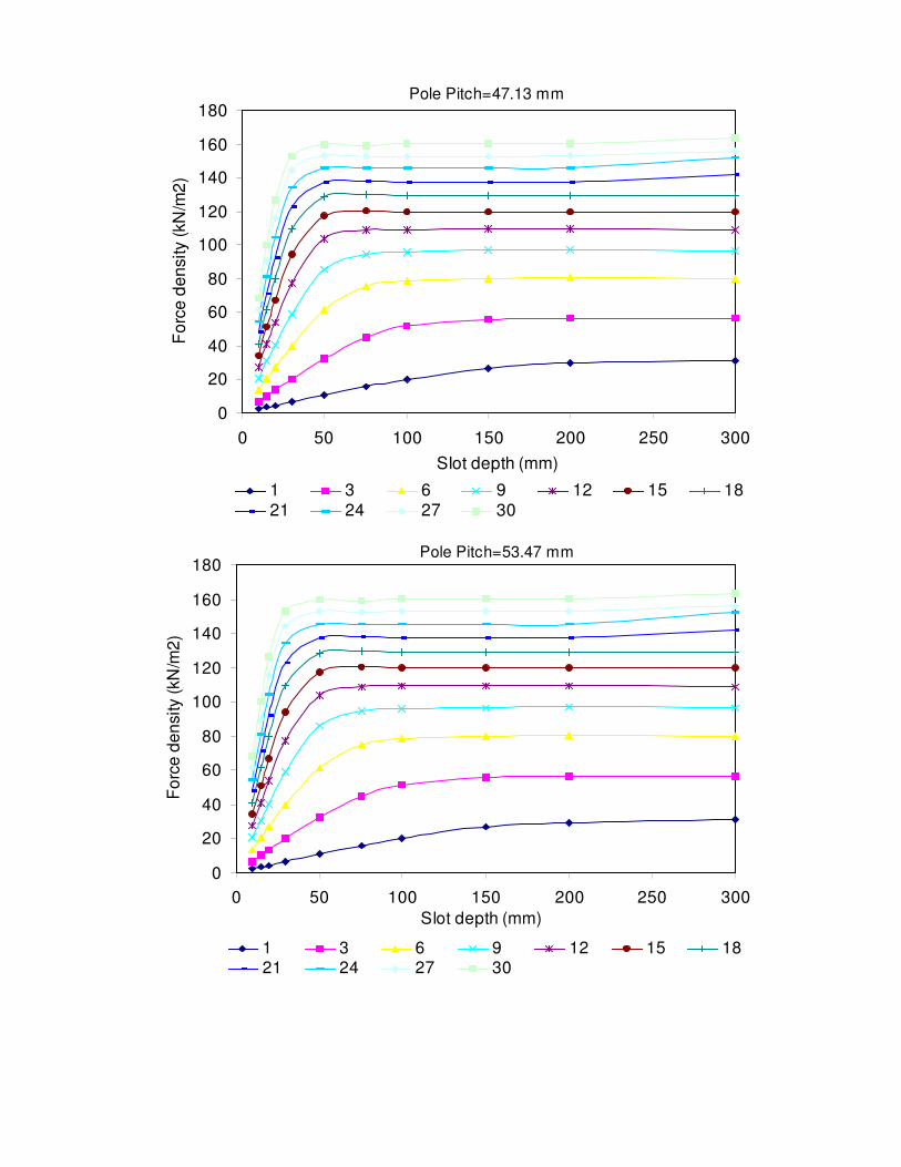
Pole Pitch=47.13 mm
0
20
40
60
80
100
120
140
160
180
0 50 100 150 200 250 300Slot depth (mm)
For
ce d
ensi
ty (k
N/m
2)
1 3 6 9 12 15 1821 24 27 30
Pole Pitch=53.47 mm
0
20
40
60
80
100
120
140
160
180
0 50 100 150 200 250 300Slot depth (mm)
For
ce d
ensi
ty (k
N/m
2)
1 3 6 9 12 15 1821 24 27 30

Pole Pitch=64.15 mm
0
20
40
60
80
100
120
140
160
180
0 50 100 150 200 250 300Slot depth (mm)
For
ce d
ensi
ty (k
N/m
2)
1 3 6 9 12 15 1821 24 27 30
Pole Pitch=74.64 mm
0
20
40
60
80
100
120
140
160
180
200
0 50 100 150 200 250 300Slot depth (mm)
Forc
e de
nsity
(kN
/m2)
1 3 6 9 12 15 1821 24 27 30

Pole Pitch=83.26 mm
0
20
40
60
80
100
120
140
160
180
200
220
0 50 100 150 200 250 300Slot depth (mm)
For
ce d
ensi
ty (k
N/m
2)
1 3 6 9 12 15 18 2124 27 30
Pole Pitch=97.38 mm
0
20
40
60
80
100
120
140
160
180
200
220
240
0 50 100 150 200 250 300
Slot depth (mm)
Forc
e de
nsity
(kN
/m2)
1 3 6 9 12 15 18 2124 27 30

Pole Pitch=109.05 mm
0
40
80
120
160
200
240
0 50 100 150 200 250 300Slot depth (mm)
Forc
e de
nsity
(kN
/m2)
1 3 6 9 12 15 1821 24 27 30
Pole P itch=128.31 mm
020406080
100120140160180200220240260
0 50 100 150 200 250 300Slot depth (mm)
For
ce d
ensi
ty (k
N/m
2)
1 3 6 9 12 15 1821 24 27 30

Pole Pitch=158.39 mm
0
40
80
120
160
200
240
280
0 50 100 150 200 250 300Slot depth (mm)
For
ce d
ensi
ty (k
N/m
2)
1 3 6 9 12 15 1821 24 27 30
Pole Pitch=188.17 m m
0
50
100
150
200
250
300
0 50 100 150 200 250 300Slot depth (mm)
For
ce d
ensi
ty (k
N/m
2)
1 3 6 9 12 15 1821 24 27 30

Pole Pitch=213.47 m m
0
40
80
120
160
200
240
280
320
0 50 100 150 200 250 300Slot depth (m m )
Forc
e de
nsity
(kN
/m2)
1 3 6 9 12 15 1821 24 27 30

Fractional-Slot Machines
Averaged force density in fractional-slot machines forvarious slot depth, current levels and density slot per poleper phase for machines having pole pitches listed in Tables4.2, 4.4 and 4.4.
APPENDIX III

q=0.375, Pole Pitch=16.48 mm
0
20
40
60
80
100
120
0 50 100 150 200 250 300Slot Depth (mm)
Forc
e D
ensi
ty (k
N/m
2)
1 3 6 9 12 15 18 2124 27 30
q=0.375, Pole Pitch=15.64 mm
0
20
40
60
80
100
120
0 50 100 150 200 250 300Slot Depth (mm)
Forc
e D
ensi
ty (k
N/m
2)
1 3 6 9 12 15 18 2124 27 30

q=0.375, Pole Pitch=17.68 mm
0
20
40
60
80
100
120
140
0 50 100 150 200 250 300Slot Depth (mm)
Forc
e D
ensi
ty (k
N/m
2)
1 3 6 9 12 15 18 2124 27 30
q=0.375, Pole Pitch=20.05 mm
0
20
40
60
80
100
120
140
0 50 100 150 200 250 300Slot Depth (mm)
For
ce D
ensi
ty (k
N/m
2)
1 3 6 9 12 15 1821 24 27 30

q=0.375, Pole Pitch=24.06 mm
0
20
40
60
80
100
120
140
160
0 50 100 150 200 250 300Slot Depth (mm)
For
ce D
ensi
ty (k
N/m
2)
1 3 6 9 12 15 18 2124 27 30
q=0.375, Pole Pitch=28 mm
0
20
40
60
80100
120
140
160
180
0 50 100 150 200 250 300Slot Depth (mm)
Forc
e D
ensi
ty (k
N/m
2)
1 3 6 9 12 15 18 2124 27 30

q=0.375, Pole Pitch=31.2 mm
020406080
100120140160180
0 50 100 150 200 250 300Slot Depth (mm)
For
ce D
ensi
ty (k
N/m
2)
1 3 6 9 12 15 1821 24 27 30
q=0.375, Pole Pitch=36.5 mm
020406080
100120140160180200
0 50 100 150 200 250 300Slot Depth (mm)
Forc
e D
ensi
ty (k
N/m
2)
1 3 6 9 12 15 18 2124 27 30

q=0.375, Pole Pitch=40.89mm
0
40
80
120
160
200
0 50 100 150 200 250 300Slot Depth (mm)
For
ce D
ensi
ty (k
N/m
2)
1 3 6 9 12 15 18 2124 27 30
q=0.375, Pole Pitch=48.12mm
020406080
100120140160180200220
0 50 100 150 200 250 300Slot Depth (mm)
Forc
e D
ensi
ty (k
N/m
2)
1 3 6 9 12 15 18 2124 27 30

q=0.375, Pole Pitch=59.40mm
0
40
80
120
160
200
240
0 50 100 150 200 250 300Slot Depth (mm)
Forc
e D
ensi
ty (k
N/m
2)
1 3 6 9 12 15 1821 24 27 30
q=0.375, Pole Pitch=70.57mm
0
26
52
78
104
130
156
182
208
234
260
0 50 100 150 200 250 300Slot Depth (mm)
Forc
e D
ensi
ty (k
N/m
2)
1 3 6 9 12 15 18 2124 27 30

q=0.375, Pole Pitch=80.05 mm
0
40
80
120
160
200
240
280
0 50 100 150 200 250 300Slot Depth (mm)
Forc
e D
ensi
ty (k
N/m
2)
1 3 6 9 12 15 18 2124 27 30

q=0.5, Pole Pitch= 20.85
0
20
40
60
80
100
120
0 50 100 150 200 250 300Slot Depth (mm)
Forc
e D
ensi
ty (k
N/m
2)
1 3 6 9 12 15 1821 24 27 30
q=0.5, Pole Pitch=21.95 mm
0
20
40
60
80
100
120
0 50 100 150 200 250 300Slot Depth (mm)
For
ce D
ensi
ty (k
N/m
2)
1 3 6 9 12 1518 21 24 27 30

q=0.5, Pole Pitch= 23.55 mm
0
20
40
60
80
100
120
0 50 100 150 200 250 300Slot Depth (mm)
For
ce D
ensi
ty (k
N/m
2)
1 6 9 12 15 18 2124 27 30
q=0.5, Pole Pitch=26.75 mm
0
20
40
60
80
100
120
0 50 100 150 200 250 300Slot Depth (mm)
Forc
e D
ensi
ty (k
N/m
2)
1 3 6 9 12 15 18 2124 27 30

q=0.5, Pole Pitch=32.07 mm
0
20
40
60
80
100
120
140
0 50 100 150 200 250 300Slot Depth (mm)
Forc
e D
ensi
ty (k
N/m
2)
1 3 6 9 12 15 1821 24 27 30
q=0.5, Pole Pitch=37.32 mm
0
20
40
60
80
100
120
140
160
0 50 100 150 200 250 300Slot Depth (mm)
For
ce D
ensi
ty (k
N/m
2)
1 3 6 9 12 1518 21 24 27 30

q=0.5, Pole Pitch=41.65 mm
0
20
40
60
80
100
120
140
160
0 50 100 150 200 250 300Slot Depth (mm)
For
ce D
ensi
ty (k
N/m
2)
1 3 6 9 12 15 1821 24 27 30
q=0.5, Pole Pitch=48.69 mm
0
20
40
60
80
100
120
140
160
180
0 50 100 150 200 250 300Slot Depth (mm)
Forc
e D
ensi
ty (k
N/m
2)
1 3 6 9 12 1518 21 24 27 30

q=0.5, Pole Pitch=54.55 mm
0
20
40
60
80
100
120
140
160
180
0 50 100 150 200 250 300Slot Depth (mm)
For
ce D
ensi
ty (k
N/m
2)
1 3 6 9 12 15 1821 24 27 30
q=0.5, Pole Pitch=64.15
020406080
100120140160180200
0 50 100 150 200 250 300Slot Depth (mm)
For
ce D
ensi
ty (k
N/m
2)
1 3 6 9 12 15 1821 24 27 30

q=0.5, Pole Pitch=79.2 mm
020406080
100120140160180200220
0 50 100 150 200 250 300Slot Depth (mm)
Forc
e D
ensi
ty (k
N/m
2)
1 3 6 9 12 15 1821 24 27 30
q=0.5, Pole Pitch=94.1 mm
020406080
100120140160180200220
0 50 100 150 200 250 300Slot Depth (mm)
For
ce D
ensi
ty (k
N/m
2)
1 3 6 9 12 15 1821 24 27 30

q=0.5, Pole Pitch=106.75 mm
020406080
100120140160180200220240
0 50 100 150 200 250 300Slot Depth (mm)
For
ce D
ensi
ty (k
N/m
2)
1 3 6 9 12 15 1821 24 27 30
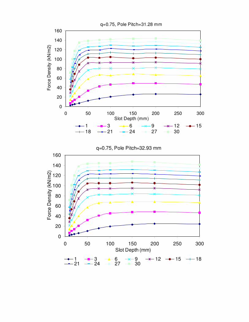
q=0.75, Pole Pitch=31.28 mm
0
20
40
60
80
100
120
140
160
0 50 100 150 200 250 300Slot Depth (mm)
Forc
e D
ensi
ty (k
N/m
2)
1 3 6 9 12 1518 21 24 27 30
q=0.75, Pole Pitch=32.93 mm
0
20
40
60
80
100
120
140
160
0 50 100 150 200 250 300Slot Depth (mm)
For
ce D
ensi
ty (k
N/m
2)
1 3 6 9 12 15 1821 24 27 30

q=0.75,Pole Pitch=35.33 mm
0
20
40
60
80
100
120
140
160
180
0 50 100 150 200 250 300Slot Depth (mm)
For
ce D
ensi
ty (k
N/m
2)
1 3 6 9 12 15 18 2124 27 30
q=0.75, Pole Pitch= 40.13 mm
0
20
40
60
80
100
120
140
160
180
0 50 100 150 200 250 300Slot Depth (mm)
For
ce D
ensi
ty (k
N/m
2)
1 3 6 9 12 15 1821 24 27 30

q=0.75, Pole Pitch=48.15
020406080
100120140160180200
0 50 100 150 200 250 300Slot Depth (mm)
For
ce D
ensi
ty (k
N/m
2)
1 3 6 9 12 1518 21 24 27 30
q=0.75, Pole Pitch=55.95 mm
020406080
100120140160180200
0 50 100 150 200 250 300Slot Depth (mm)
For
ce D
ensi
ty (k
N/m
2)
1 3 6 9 12 15 1821 24 27 30

q=0.75 Pole Pitch=73.05 mm
020406080
100120140160180200220240
0 50 100 150 200 250 300Slot Depth (mm)
Forc
e D
ensi
ty (k
N/m
2)
1 3 6 9 12 1518 21 24 27 30
q=0.75,Pole Pitch= 62.48 mm
020406080
100120140160180200220
0 50 100 150 200 250 300Slot Depth (mm)
For
ce D
ensi
ty (k
N/m
2)
1 3 6 9 12 15 1821 24 27 30

q=0.75, Pole Pitch=81.83
020406080
100120140160180200220240
0 50 100 150 200 250 300Slot Depth (mm)
Forc
e D
ensi
ty (k
N/m
2)
1 3 6 9 12 1518 21 24 27 30
q=0.75, Pole Pitch= 96.25 mm
020406080
100120140160180200220240260
0 50 100 150 200 250 300Slot Depth (mm)
For
ce D
ensi
ty (k
N/m
2)
1 3 6 9 12 15 1821 24 27 30

q=0.75, Pole Pitch=118 mm
020406080
100120140160180200220240260280
0 50 100 150 200 250 300Slot Depth (mm)
For
ce D
ensi
ty (k
N/m
2)
1 3 6 9 12 1518 21 24 27 30
q=0.75, Pole Pitch=141.15 mm
020406080
100120140160180200220240260280300
0 50 100 150 200 250 300Slot Depth (mm)
Forc
e D
ensi
ty (k
N/m
2)
1 3 6 9 12 15 1821 24 27 30

q=0.75, Pole Pitch=160.13 mm
020406080
100120140160180200220240260280300320
0 50 100 150 200 250 300Slot Depth (mm)
For
ce D
ensi
ty (k
N/m
2)
1 3 6 9 12 15 1821 24 27 30

References
1. Hamdi, E.S. “ Permanent magnet and variable reluctance drive systems” , ETIPress,Gothenburg, Sweden, 2003.
2. Essam S. Hamdi. “ Design Of Small Electrical Machines” , John Wiley& Sons Ltd.
3. A Grauers, "Design of Direct-driven Permanent-magnet Generatorsfor Wind Turbines", Ph.D. dissertation, Dept. Electric Power Eng.,Chalmers Univ. of Technology, Göteborg, Sweden, 1996.
4. P. Kasinathan, A Grauers and E Hamdi "Force Density in Low-speedPM Machines: Saturation limits” , Proc. 2002 IEEE PowerEngineering Society, Submitted.
5. A.Grauers, P.Kasinathan, “ Force Density in Low-speed PM:“ Temperature and Inductance limits” , Proc. 2002 IEEE PowerEngineering Society, Submitted.
6. Murugesen, S: “ An overview of electric motors for spaceapplications” , IEEE Transcations On Industrial, Electronics AndControl Instrumentation, Vol. IECI-28, No. 4, November 1981,pp261-265
7. S. K. Pal, "Direct drive high energy permanent magnet brush andbrushless DC motors for robotic applications, ” in Robot Actuators,IEE Colloquium on, 1991, pp. 12/1-12/4.
8. L. M. C. Mhango, “ Brushless DC machines with rare-earth magnetsfor high speed aerospace drives, ” presented at,6-7 Nov. 1990,Birmingham, UK, 1990.
9. L. M. C. Mhango and R. Perryman, “ An assessment of high powerdensity brushless DC motor technology with neodymium-iron-boronexcitation” , presented at 1994 Universities Power EngineeringConference (UPEC),14-16 Sept. 1994, Galway, Ireland, 1994.
10. L. M. C. Mhango, “ Design ideas for low-inertia high-speedelectronically commutated PM motors for special applications” , inVariable Speed Drives and Motion Control, IEE Colloquium on, 1992,pp. 9/1-9/5.
11. S. K. Pal, “ Comparative study of the design and development of directdrive brushed and brushless DC motors with samarium cobalt,neodymium-iron-boron and ceramic magnets” , in Permanent MagnetMachines and Drives, IEE Colloquium on, 1993, pp. 7/1-7/7.
12. S. K. Pal, “ Comparative study of the design and manufacturingprocesses of electrical motors with low and high energy permanentmagnets” , in Electrical Machines and Drives, 1993. Sixth InternationalConference on (Conf. Publ. No. 376), 1993, pp. 339-346.

13. Fink, R.A.: “ The brushless motor-types and sources” , ControlEngineering, August 1970, pp.42-45.
14. Knights, D E: “ Prospects for the printed motor” , Design Engineering,March 1975, pp.199-202.
15. Hans Waagen: “ Motors with printed circuit armatures” , DesignEngineering, January 1970, pp.52-55.
16. Casanova D: “ The permanent magnet dish motor an assessment of thequality of mechanical commutation” , Motorcon Proceedings,September 1982, pp.446-450.
17. Werninck, E.H: “ The methodology of motor selection” , SecondInternational Conference on Small and Special Electrical Machines,IEE Conference Publication No. 202, 22-24 September 1981, pp1-5.
18. Carl M. Fink and Dennis F. Brown: “ The permanent magnet dcpancake motor-An assesment of the quality of mechanicalcommutation” , Motorcon, March 1982, pp693-699.
19. Mazurkiewcz, J.: “ Consider hollow-rotor motors” , Electronic Design11, May 24, 1975, pp.76-79.
20. Mazurkiewcz, J.: “ The drive motor of a servo” , Electronic Design 15,July 19, 1976, pp.110-113.
21. Theodore Wildi.: “ Electrical machines, drives and power systems”pp.417-436.
22. Wang Zong-pei, Cheng Shu-Kang.: “ Bipolar drive three phasevariable reluctance step motor” , Second International Conference onSmall and Special Electrical Machines, IEE Conference PublicationNo. 202, 22-24 September 1981, pp50-54.
23. A Huges, D.J.MacLoed.: “ Hybrid and variable reluctance small-anglestepping motors” , Second International Conference on Small andSpecial Electrical Machines, IEE Conference Publication No. 202, 22-24 September 1981, pp50-54.
24. Acarnley, P.P.: “ Stepping motor control techniques” , Conference onDrives/Motors/Controls, 24-26 October 1984, Brighton,UnitedKingdom, pp106-112.
25. Bimbra, P.S.: “ Generlized theory of electrical machines” , FifthEdition, Khanna Publishes,pp1034-1036.
26. Caricchi F., Crescimbini F., Honorati O., Di Napoli A., Santini E.,“ Compact Wheel Direct Drive for Evs” , Industry ApplicationsMagazine, IEEE, 1996
27. Spooner E., Chalmers B.J., “ TORUS: A Slotless, Toroidal-Stator,Permanent Magnet Generator” , Proceedings-B, IEE, Nov. 1992, Vol.139, No.6
28. Caricchi F., Crescimbini F., Mezzeti F., Santini E., “ MultistageAxial-Flux PM Machine for Wheel Direct Drive” , Transaction onIndustry Applications, IEEE, 1996, Vol. 32, No.4

29. Caricchi F., Crescimbini F., Honorati O.,“ Modular Axial-FluxPermanent Magnet Motor for Ship Propulsion Drives” , Transaction onEnergy Conservation, IEEE, 1999, Vol. 14, No.3
30. Caricchi F., Crescimbini F., Fedeli E., Noia G., “ Design andConstruction of a Wheel-Directly-Coupled Axial-Flux PM MotorPrototype for EVs”
31. J. G. W. West, “ PM DC motors with series field characteristics” , inPermanent Magnet Machines, IEE Colloquium on, 1988, pp. 5/1-5/5.
32. J. G. W. West, “ DC, induction, reluctance and PM motors for electricvehicles", in Power Engineering Journal, vol. 8, 1994, pp. 77-88.
33. J. G. W. West, “ The present status of electrical machines in vehicles",Machines for Automotive Applications (Digest No. 1996/166), IEEColloquium on, 1996, pp. 1/1-121.
34. J. G. W. West, “ Propulsion systems for hybrid electric vehicles",Electrical Machine Design for All-Electric and Hybrid-ElectricVehicles (Ref. No. 1999/196), IEE Colloquium on, 1999, pp. 1/1-1/9.
35. J Hystad, "Transverse Flux Generators in Direct-driven Wind EnergyConverters", Ph.D. dissertation, Dept. Electrical Power Eng., NTNU,Trondheim, Norway, 2000.
36. Hasan El Hinaoui, “ Green Car, Traction Motors” PhD project.37. D.A.Staton, R.P.Deodhar, W.L.Soong and T.J.E.Miller., “ Torque
Prediction Using the Flux-Mmf Diagram in AC, DC, and ReluctanceMotors.” , Transactions on Industry Application, IEEE, vol.32, no 1,Jan/Feb 1996
38. SGM Magnets Limited Catalogue, Sussex, United Kingdom39. Magnet Application Catalogue, United Kingdom