integrated solutions - enerpac · pdf fileenerpac integrated solutions ... bridge launching...
TRANSCRIPT
Integrated Solutions
www.enerpac.com2 wwwwwwwwwwwwwwwwwwwwwwwwwwwwwwwwwwwwwwwwwwwwwwwwwwwwwwwwwwww.en.en.en.en.en.en.en.en.en.en.en.en.en.enenenen.enerperperperperperperperperperperperperperprperperpperperpac.ac.ac.acac.ac.acacac.acacacac.ac.acacacca comcomcomcomcomcomcomcomcomcomcomcomcomcomcomcommmcomwww.enerpac.com222222222222222222
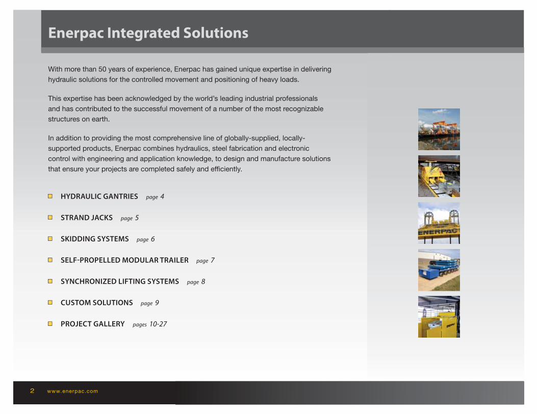
Enerpac Integrated Solutions
■■ HYDRAULIC GANTRIES page 4
■■ STRAND JACKS page 5
■■ SKIDDING SYSTEMS page 6
■■ SELF-PROPELLED MODULAR TRAILER page 7
■■ SYNCHRONIZED LIFTING SYSTEMS page 8
■■ CUSTOM SOLUTIONS page 9
■■ PROJECT GALLERY pages 10-27
With more than 50 years of experience, Enerpac has gained unique expertise in delivering
hydraulic solutions for the controlled movement and positioning of heavy loads.
This expertise has been acknowledged by the world’s leading industrial professionals
and has contributed to the successful movement of a number of the most recognizable
structures on earth.
In addition to providing the most comprehensive line of globally-supplied, locally-
supported products, Enerpac combines hydraulics, steel fabrication and electronic
control with engineering and application knowledge, to design and manufacture solutions
that ensure your projects are completed safely and effi ciently.
3INTEGRATED SOLUTIONS 3INTEGRATED SOLUTIONS
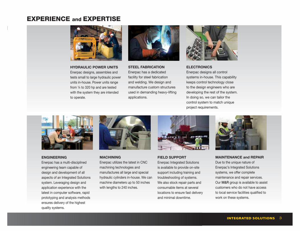
ELECTRONICS
Enerpac designs all control
systems in-house. This capability
keeps control technology close
to the design engineers who are
developing the rest of the system.
In doing so, we can tailor the
control system to match unique
project requirements.
MAINTENANCE and REPAIR
Due to the unique nature of
Enerpac’s Integrated Solutions
systems, we off er complete
maintenance and repair services.
Our M&R group is available to assist
customers who do not have access
to local service facilities qualifi ed to
work on these systems.
STEEL FABRICATION
Enerpac has a dedicated
facility for steel fabrication
and welding. We design and
manufacture custom structures
used in demanding heavy-lifting
applications.
ENGINEERING
Enerpac has a multi-disciplined
engineering team capable of
design and development of all
aspects of an Integrated Solutions
system. Leveraging design and
application experience with the
latest in computer software, rapid
prototyping and analysis methods
ensures delivery of the highest
quality systems.
MACHINING
Enerpac utilizes the latest in CNC
machining technologies and
manufactures all large and special
hydraulic cylinders in-house. We can
machine diameters up to 50 inches
with lengths to 240 inches.
HYDRAULIC POWER UNITS
Enerpac designs, assembles and
tests small to large hydraulic power
units in-house. Power units range
from ¼ to 320 hp and are tested
with the system they are intended
to operate.
FIELD SUPPORT
Enerpac Integrated Solutions
is available to provide on-site
support including training and
troubleshooting of systems.
We also stock repair parts and
consumable items at several
locations to ensure fast delivery
and minimal downtime.
EXPERIENCE and EXPERTISE

www.enerpac.com4
Hydraulic Gantries
Capacity(with 4 towers)
(tons)
1st stage 2nd stage 3rd stage
Model Number
Lift Height
(in)
1st stage 2nd stage 3rd stage
Weight(per
tower)(lbs)
67 67 n/a SL60 133 195 n/a 2,315
141 141 n/a SL125 182 264 n/a 4,696
441 441 215 SL400 193 266 335 11,464
573 573 330 SBL500 195 270 337 14,330
1,010 653 357 SBL1000 195 270 337 18,850
1,178 759 423 SBL1100 276 381 473 26,345
562 562 n/a MBL500 n/a* 507 n/a* 43,541
674 674 n/a MBL600 n/a* 573 n/a* 48,502
*Extends simultaneously through all stages with constant lifting capacity
OVERVIEWHYDRAULIC GANTRIES
KEY FEATURES:
• Self-contained hydraulics and electronics
• Intelli-Lift wireless control system
• Self-propelled wheels or tank rollers
• Foldable boom on SBL1100, MBL500 and MBL600
• Full range of supplementary equipment: header beams, lifting lugs, side shift, skid tracks
• All gantries are ASME B30.1 compliant
The complete range of hydraulic gantries for your
most demanding lifting and rigging operations
Hydraulic Gantries are a safe, effi cient way to lift
and position heavy loads in applications where
traditional cranes will not fi t and permanent
overhead structures for job cranes are not
an option.
Hydraulic Gantries are placed on skid tracks to
provide a means for moving and placing heavy
loads, many times with only one pick.
Enerpac off ers three series of Hydraulic Gantry
systems:
• the cost eff ective SL-Series off ers entry level
control and capacity
• the heavy duty SBL-Series off ers capacities up to
1,200 tons and 3-stage lifting capability through
the boom structure
• the MBL-Series incorporates all features of the
SBL-Series and off ers full lifting capacity over
the full stroke. The MBL Gantries have been
designed with increased footprint stability and
can therefore lift using 2 legs as well as 4.
All Enerpac gantries are delivered with specifi c
properties and control systems to ensure optimum
stability and safety.
Shown: SBL1100
5
Strand Jack
Capacity
(tons)
StrandDiameter
(in)
Model Number
Number of
Strands
Weight
(lbs)
17 0.71 HSL1507 1 220
34 0.62 HSL3006 3 1,102
51 0.71 HSL4507 3 1,102
67 0.71 HSL6007 4 1,433
79 0.62 HSL7006 7 1,411
112 0.71 HSL10007 7 1,874
225 0.62 HSL20006 19 2,866
225 0.71 HSL20007 12 3,086
337 0.62 HSL30006 31 4,806
337 0.71 HSL30007 19 4,806
506 0.71 HSL45007 31 6,724
562 0.62 HSL50006 48 6,945
731 0.71 HSL65007 43 8,708
955 0.71 HSL85007 55 11,023
1,124 0.71 HSL100007 66 16,865
1,405 0.71 HSL125007 84 18,298
OVERVIEW
INTEGRATED SOLUTIONS
KEY FEATURES:
• Full control of lifting and lowering through SCC control
• Two sizes strand diameter: 0.62 in. and 0.71 in.
• Complete line of electric and diesel power packs
• Nickel plated telescopic pipes preventing bird caging
• Standard supplied with lifting anchor
• Automated locking – unlocking operation
• Special corrosion treated high endurance multi-use wedges
• Full range of accessories: strand dispenser, strand guide, re-coiler
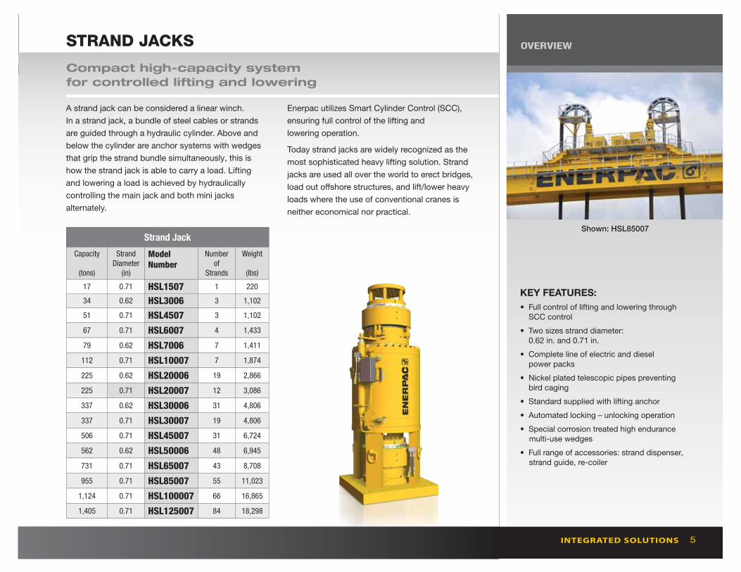
Compact high-capacity system
for controlled lifting and lowering
A strand jack can be considered a linear winch.
In a strand jack, a bundle of steel cables or strands
are guided through a hydraulic cylinder. Above and
below the cylinder are anchor systems with wedges
that grip the strand bundle simultaneously, this is
how the strand jack is able to carry a load. Lifting
and lowering a load is achieved by hydraulically
controlling the main jack and both mini jacks
alternately.
Enerpac utilizes Smart Cylinder Control (SCC),
ensuring full control of the lifting and
lowering operation.
Today strand jacks are widely recognized as the
most sophisticated heavy lifting solution. Strand
jacks are used all over the world to erect bridges,
load out off shore structures, and lift/lower heavy
loads where the use of conventional cranes is
neither economical nor practical.
STRAND JACKS
Shown: HSL85007

www.enerpac.com6
Skidding Systems
Capacity(per shoe)
(tons)
Model Number
Skid Shoe
Stroke
Push/Pull
Cylinders(in)
Stroke
Lifting
Cylinder(in)
Weight(per shoe)
(lbs)
140 HSK1250beam
jack
24
24
n/a
6.9
1,631
1,742
280 HSK2500beam
jack
24
24
n/a
6.9
2,249
3,197
225 HSKLH2000 beam 24 n/a 750
OVERVIEWSKIDDING SYSTEMS
An ancient technology meets the 21st century
The HSK skidding system is comprised of a series
of skid-shoes powered by hydraulic push-pull
cylinders, travelling over a pre-constructed track.
A series of special PTFE coated blocks are placed
on the skid-tracks. The PTFE surface is matched
with a sliding plate under the Enerpac skid shoes,
designed to achieve minimum friction coeffi cients.
The skid shoes are connected by hoses to a
hydraulic electric or diesel driven power pack.
In addition to our standard skidding systems we
have the capabilities to create customized skidding
systems to meet your specifi c requirements.
Enerpac Skidding Systems are available in
three versions:
• HSK1250 with a capacity of 140 tons per skid unit
• HSK2500 with a capacity of 280 tons per skid unit
• HSKLH2000 with a capacity of 225 tons per skid
unit and a lower collapsed height
The HSK1250 and HSK2500 skidding systems are
available in 2 varieties: using a “skid shoe jack” or
a “skid shoe beam”. The skid shoe jack includes
an integrated lifting cylinder. A skid shoe beam is
designed for skidding purposes only.
To calculate the minimum required capacity per
shoe, the entire load has to be able to rest safely
on 2 of the 4 shoes. To skid a load of 500 tons, the
required skidding system is HSK2500.
KEY FEATURES:
• PTFE skid pads with dimpled surface for low friction and long lifetime
• Easy to replace skid pads, no tools necessary
• Unique gripper anchor system complete with lever for easy selection of skidding direction
• Double acting hydraulic cylinders with suffi cient capacity in both push and pull direction. No need to turn the skid shoe for reverse skidding direction
• Large load support surface on the skid beam
• Bottom of skid shoes equipped with stainless steel sliding plates
Shown: HSK1250
7
Self-Propelled Modular Trailer
Capacity
(per unit)
(tons)
Model Number
Transport Speed
(1 unit)
Steering Range
degrees
Lifting Range
(in)
Collapsed Height
(in)
Length
(in)
Width
(in)
Weight
(lbs) unloaded
(mph)loaded(mph)
67 SPMT600 2.1 0.9 -175º to +175º 14 30 121 91 15,101
OVERVIEW
INTEGRATED SOLUTIONS
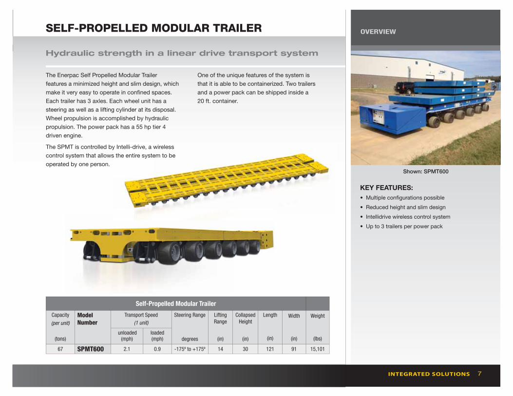
SELF-PROPELLED MODULAR TRAILER
Hydraulic strength in a linear drive transport system
The Enerpac Self Propelled Modular Trailer
features a minimized height and slim design, which
make it very easy to operate in confi ned spaces.
Each trailer has 3 axles. Each wheel unit has a
steering as well as a lifting cylinder at its disposal.
Wheel propulsion is accomplished by hydraulic
propulsion. The power pack has a 55 hp tier 4
driven engine.
The SPMT is controlled by Intelli-drive, a wireless
control system that allows the entire system to be
operated by one person.
One of the unique features of the system is
that it is able to be containerized. Two trailers
and a power pack can be shipped inside a
20 ft. container.
KEY FEATURES:
• Multiple confi gurations possible
• Reduced height and slim design
• Intellidrive wireless control system
• Up to 3 trailers per power pack
Shown: SPMT600
www.enerpac.com8
SYNCHRONOUS LIFTING
Lift Points
Model Number
Integrated Pump
Accuracy Touch Screen Control
Options
Levelling Weighing CG Expandable
4,8,12 EVO yes 0.04 yes yes yes yes yes
4,8 EVO-B no 0.04 yes no yes* no no
* 4-point system includes weighing function
SYNCHRONOUS LIFTING SYSTEMS OVERVIEW
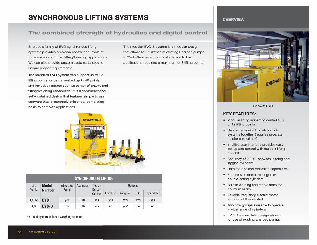
The combined strength of hydraulics and digital control
KEY FEATURES:
• Modular lifting system to control 4, 8 or 12 lifting points
• Can be networked to link up to 4 systems together (requires separate master control box)
• Intuitive user interface provides easy set-up and control with multiple lifting options
• Accuracy of 0.040" between leading and lagging cylinders
• Data storage and recording capabilities
• For use with standard single- or double-acting cylinders
• Built in warning and stop alarms for optimum safety
• Variable frequency electric motor for optimal fl ow control
• Two fl ow groups available to operate a wide range of cylinders
• EVO-B is a modular design allowing for use of existing Enerpac pumps
Enerpac’s family of EVO synchronous lifting
systems provides precision control and levels of
force suitable for most lifting/lowering applications.
We can also provide custom systems tailored to
unique project requirements.
The standard EVO system can support up to 12
lifting points, or be networked up to 48 points,
and includes features such as center of gravity and
tilting/weighing capabilities. It is a comprehensive
self-contained design that features simple to use
software that is extremely effi cient at completing
basic to complex applications.
The modular EVO-B system is a modular design
that allows for utilization of existing Enerpac pumps.
EVO-B off ers an economical solution to basic
applications requiring a maximum of 8 lifting points.
Shown: EVO

INTEGRATED SOLUTIONS 9
CUSTOM SOLUTIONS
SYNCHRONOUS HOISTING
STRAND JACK GANTRY
BRIDGE LAUNCHING
SELF-ERECTING TOWER
A unique crane product for
below-the-hook positioning
of heavy loads that require
precision placement. May
reduce the number of cranes
needed and reduce the costs
for multiple picks.
The strand jack gantry is a
steel structure to facilitate
lifting and skidding back,
forth and sideways of heavy
loads. The Enerpac strand
jack gantry allows you to
operate in confi ned spaces.
The system consists of 3 major components:
• Steel Construction
• Strand Jacks for vertical lifting
• Skidding System for horizontal skidding
This is powered by a hydraulic power unit that is situated on ground
level. The capacity, height and width of the construction can be modifi ed
in cooperation with our engineering team.
Providing a solution for the most
complex and demanding bridge
construction applications, Enerpac
has over 20 years experience
providing unique custom bridge
launching systems.
The Enerpac Self-Erecting Tower (ESET) is a self-erecting
tower lift system that enables you to build a free standing
gantry from ground level. The Self-Erecting Tower can be
supplied in various capacities and heights and is built with
standard modular components, enabling a fl exible solution
to future project demands.
The Self-Erecting Tower enables moving the load in all
directions: lifting, lowering, skidding back and forth, and
has side shift capabilities. Lifting and skidding are achieved
using standard Enerpac strand jacks that can also be used
for other applications.
The Self-Erecting Tower is a versatile lift-system that can be used in a wide variety of
applications, for example the installation of reactor vessels in a petrochemical plant or
erecting a shipyard crane. When compared with large capacity cranes, the Self-Erecting
Tower signifi cantly reduces transportation and set up costs.
www.enerpac.comwww.enerpac.comwwwwwwwwwwwwwwwwwwwwwwwwwwwwwwwwwwwwwwwwwwwwwwwwwwwwwwwwwwww.en.en.en.en.en.en.en.en.en.en.en.en.enenenenn.en.ee erperperperperperperperperperperperperperperperprperpac.ac.ac.ac.ac.ac.acacacacac.acacacacaac.aaca comcomcomcomcomcomcomcomcomcomcomcomcomcomcomcommmcwww.enerpac.com10
PROJECT GALLERY
INFRASTRUCTURE pages 11-13
POWER GENERATION pages 14-15
OFFSHORE pages 16-17
OIL AND GAS pages 18-19
MINING pages 20-22
SHIPBUILDING page 23
ENTERTAINMENT pages 24-25
PETROCHEMICAL pages 26-27

11
NEED NEW PHOTO
NEED NEW PHOTO
INTEGRATED SOLUTIONS
INFRASTRUCTURE
A new 0.9 mile long bridge connects the east and west sides of Nijmegen, the oldest city in the Netherlands.
Construction required the lifting and precisely positioning of concrete and steel assemblies.
During the concrete casting a series of linked Enerpac cylinders supported the formwork and concrete
structures. Enerpac Strand Jacks were used to tension the arches of the bridge and to lift the 935 ft.
long main span onto the structure of the bridge.
■■ PROJECT City Bridge Nijmegen
■■ LOCATION Nijmegen, The Netherlands
■■ YEAR 2012-2013
■■ EQUIPMENT HSL-SERIES HEAVY LIFTING STRAND JACKS
RR-SERIES HYDRAULIC CYLINDERS AND SPECIAL PUMPS

www.enerpac.com12
INFRASTRUCTURE
State–of–the–art hydraulics are facilitating the construction of the new San Francisco – Oakland Bay Bridge.
Enerpac Strand Jacks and Synchronous Lift Systems were used to erect key components of the bridge. The
1800 ton transition spans were lifted from a barge and raised to deck level using several 300 ton strand jacks.
These spans link the east skyway to the self-anchored suspension (SAS) span. For the SAS tower, sections
were raised into position using 650 ton strand jacks and then levelled using a 4 point synchronous lift system.
■■ PROJECT San Francisco-Oakland Bay Bridge
■■ LOCATION San Francisco, California, USA
■■ YEAR 2005-2013
■■ EQUIPMENT HSL-SERIES HEAVY LIFTING STRAND JACKS
13INTEGRATED SOLUTIONS
INFRASTRUCTURE
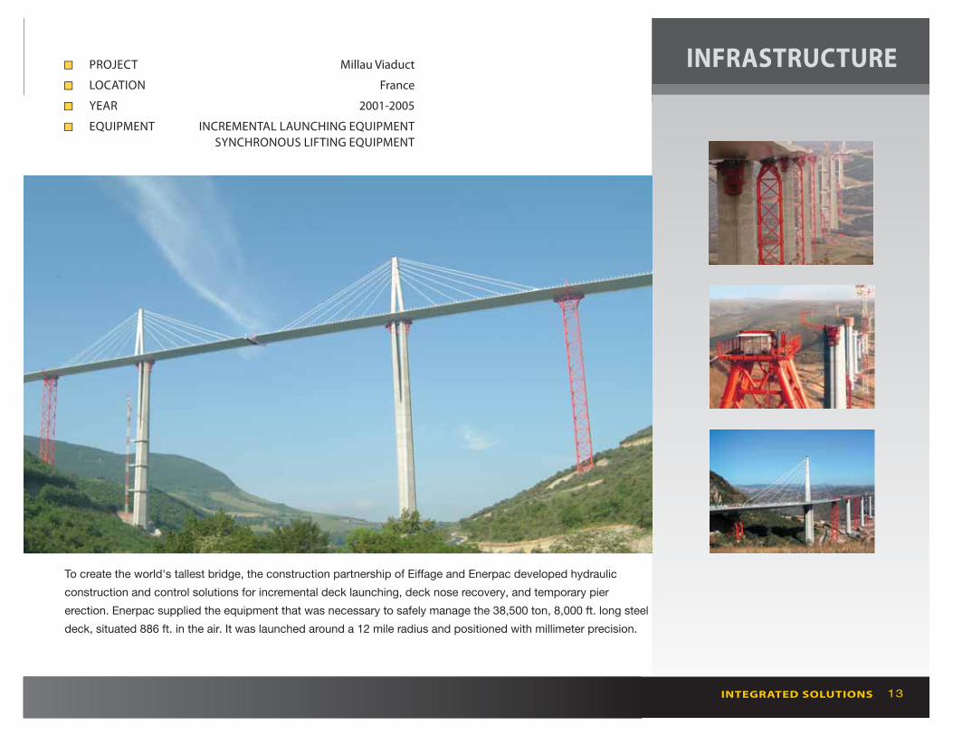
To create the world's tallest bridge, the construction partnership of Eiff age and Enerpac developed hydraulic
construction and control solutions for incremental deck launching, deck nose recovery, and temporary pier
erection. Enerpac supplied the equipment that was necessary to safely manage the 38,500 ton, 8,000 ft. long steel
deck, situated 886 ft. in the air. It was launched around a 12 mile radius and positioned with millimeter precision.
■■ PROJECT Millau Viaduct
■■ LOCATION France
■■ YEAR 2001-2005
■■ EQUIPMENT INCREMENTAL LAUNCHING EQUIPMENT
SYNCHRONOUS LIFTING EQUIPMENT

www.enerpac.com14
POWER GENERATION
An SBL1100 hydraulic gantry was used to install diesel/gas generators and alternator sets each weighing
hundreds of tons at the new Owen Springs Power Station near Alice Springs in the desert heart of Australia.
The three, 14,000 hp diesel gas generators were unloaded onto their respective foundations in a single
operation. The gantry’s lifting height and side shift capability enabled the equipment to be maneuvered into
their bays sideways.
■■ PROJECT Positioning Equipment Owen Springs Power Station
■■ LOCATION Alice Springs, Australia
■■ YEAR 2012
■■ EQUIPMENT SBL-SERIES HYDRAULIC GANTRY
15INTEGRATED SOLUTIONS
POWER GENERATION
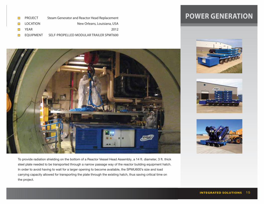
To provide radiation shielding on the bottom of a Reactor Vessel Head Assembly, a 14 ft. diameter, 3 ft. thick
steel plate needed to be transported through a narrow passage way of the reactor building equipment hatch.
In order to avoid having to wait for a larger opening to become available, the SPMU600’s size and load
carrying capacity allowed for transporting the plate through the existing hatch, thus saving critical time on
the project.
■■ PROJECT Steam Generator and Reactor Head Replacement
■■ LOCATION New Orleans, Louisiana, USA
■■ YEAR 2012
■■ EQUIPMENT SELF-PROPELLED MODULAR TRAILER SPMT600

www.enerpac.com16
OFFSHORE
The MCS Napoli was caught in a storm and was beached in Lyme Bay in 2007. The ship cracked and was broken
up into sections. The 3,800 ton back of the ship, measuring 213 ft. by 118 ft., was hoisted onto two pontoons
using 24 hydraulically operated chain pullers, each with a lifting capacity of 250 tons. Once on the pontoon, the
wreck was sawn into pieces before being transported to land.
■■ PROJECT Napoli Vessel Salvage
■■ LOCATION English Channel, United Kingdom
■■ YEAR 2009
■■ EQUIPMENT CHAIN PULLERS
17
PROJECT: VT HALTER SHIP
LOADING
LOCATION: PASCAGOULA,
MISSISSIPPI
YEAR: 2011
EQUIPMENT: CUSTOM ESS
SYNCHRONOUS LIFT SYSTEM
INTEGRATED SOLUTIONS
OFFSHORE
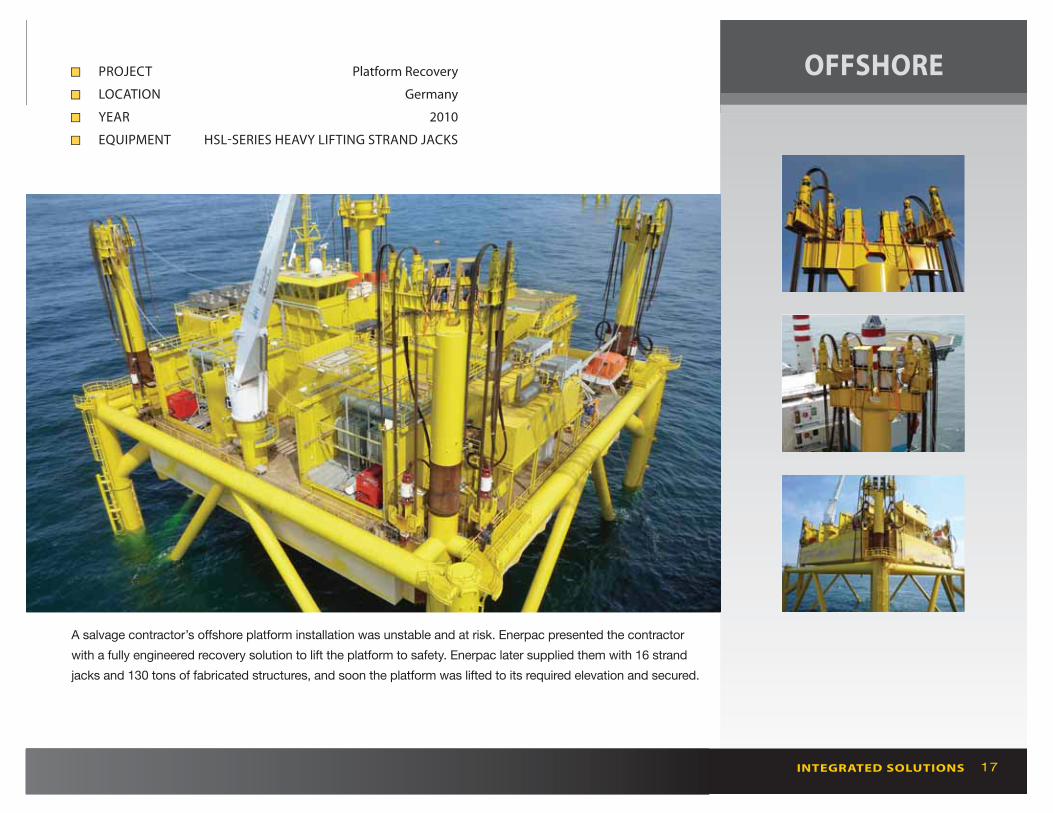
A salvage contractor’s off shore platform installation was unstable and at risk. Enerpac presented the contractor
with a fully engineered recovery solution to lift the platform to safety. Enerpac later supplied them with 16 strand
jacks and 130 tons of fabricated structures, and soon the platform was lifted to its required elevation and secured.
■■ PROJECT Platform Recovery
■■ LOCATION Germany
■■ YEAR 2010
■■ EQUIPMENT HSL-SERIES HEAVY LIFTING STRAND JACKS

www.enerpac.com18
OIL and GAS
Construction of the world's fi rst LGN regasifi er, built with 118,000 cubic yards of cement and 33,000 tons of
steel, required lifting and skidding solutions that could stand up to these extreme conditions. Enerpac HSK-
Series skidding systems, in conjunction with HSL-Series heavy lifting strand jacks, provided the solution, which
compensated for skidding on uneven ground, and lifting deck modules and equipment of up to 3,300 tons.
■■ PROJECT Adriatic LNG
■■ LOCATION Porto Levente, Italy
■■ YEAR 2007
■■ EQUIPMENT HSK-SERIES SKIDDING SYSTEM
HSL-SERIES HEAVY LIFTING STRAND JACKS

19INTEGRATED SOLUTIONS
OIL and GAS
During construction of a Tension Leg Platform, which will serve as an offshore production facility in the Gulf of Mexico
and is projected to be located in water depths of in excess of 5,000 ft., Enerpac strand jacks were utilized for loading
out the utility, drilling, and process modules. Each of these modules weighed approximately 7,000 tons and required
1,500 tons of pulling force during the load-out procedure.
■■ PROJECT Off shore Production Facility
■■ LOCATION Gulf of Mexico
■■ YEAR 2013
■■ EQUIPMENT 4 x HSL6500 with 65kW HPUs and Controls

www.enerpac.com20
MINING
An Enerpac Strand Jack Lifting system was employed to construct Australia’s largest ever magnetite mining
and processing operation. With the HSL-series strand jack system, pairs of 800 ton iron ore mills and 1,540
ton autogenous mills were lifted and then lowered onto their bearings 70 ft. above the ground.
■■ PROJECT Sino Iron Ore
■■ LOCATION Cape Preston, Australia
■■ YEAR 2009
■■ EQUIPMENT HSL-SERIES HEAVY LIFTING STRAND JACKS
21INTEGRATED SOLUTIONS
MINING
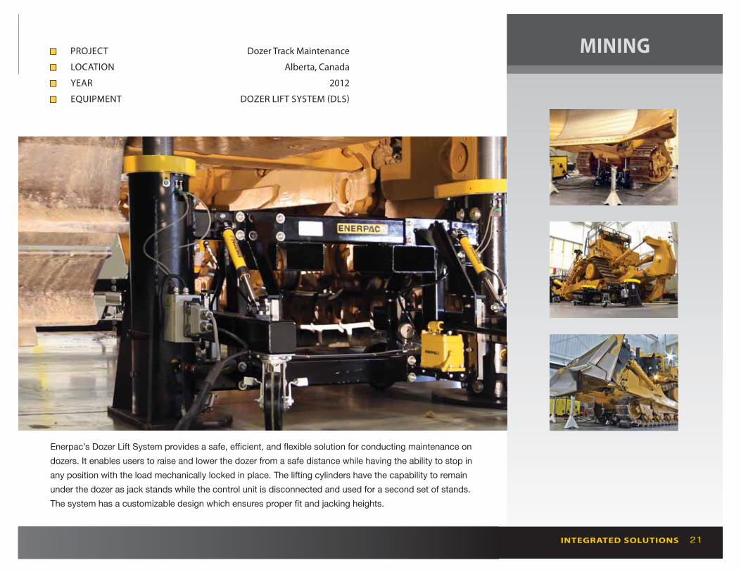
Enerpac’s Dozer Lift System provides a safe, effi cient, and fl exible solution for conducting maintenance on
dozers. It enables users to raise and lower the dozer from a safe distance while having the ability to stop in
any position with the load mechanically locked in place. The lifting cylinders have the capability to remain
under the dozer as jack stands while the control unit is disconnected and used for a second set of stands.
The system has a customizable design which ensures proper fi t and jacking heights.
■■ PROJECT Dozer Track Maintenance
■■ LOCATION Alberta, Canada
■■ YEAR 2012
■■ EQUIPMENT DOZER LIFT SYSTEM (DLS)

www.enerpac.com22
MINING
Minimizing equipment downtime is critical to mining operations. Enerpac provided a solution for high
capacity, safe, and effi cient shovel maintenance lifting. The Enerpac Synchronous Lifting System
automatically lifts and lowers cylinders in unison negating the need for multiple jack operators.
Synchronized lifting has increased safety and productivity.
■■ PROJECT Electric Rope Shovel Maintenance
■■ LOCATION Calama, Chile
■■ YEAR 2009
■■ EQUIPMENT SYNCHRONOUS LIFTING SYSTEM

23
PROJECT: VT HALTER SHIP
LOADING
LOCATION: PASCAGOULA,
MISSISSIPPI
YEAR: 2011
EQUIPMENT: CUSTOM ESS
SYNCHRONOUS LIFT SYSTEM
INTEGRATED SOLUTIONS
SHIPBUILDING
The Enerpac SyncHoist system enhances crane performance and safety, off ering horizontal and vertical load
maneuvering. A system of 4 x 110 metric ton cylinders with 1,500 mm stroke lengths was used with one crane to
align the steel blocks of the ship’s control tower sections. The SyncHoist system allowed a gradual lift of the load
and dynamic adjustment in relation to the center of gravity during the lift.
■■ PROJECT Hoisting Ship Sections
■■ LOCATION Williamstown, Australia
■■ YEAR 2012
■■ EQUIPMENT SHS-SERIES SYNCHRONOUS HOISTING SYSTEM

www.enerpac.com24
ENTERTAINMENT
The skyline in Las Vegas has changed thanks to the construction of the 550 ft. High Roller Observation
Wheel. Enerpac supplied two major components for the wheel. The fi rst and major component was the
Mechanization System which is the primary system used to drive the wheel every day for the expected
50 year life span. The second component was the HRM (Hydraulic Rotating Mechanism) which was
used to erect the rim of the wheel.
■■ PROJECT Vegas High Roller Observation Wheel
■■ LOCATION Las Vegas, Nevada, USA
■■ YEAR 2014
■■ EQUIPMENT MECHANIZATION SYSTEM & HYDRAULIC ROTATING MECHANISM

25INTEGRATED SOLUTIONS
ENTERTAINMENT
A Synchronous Lifting and Climbing System was used to assemble and dismantle the 230 ton stage
construction for U2’s 360˚ Tour. The steel construction consisted of a central block that rests upon four legs,
each made up of six sections. The central block was gradually lifted off the ground in 38 steps and a section
was added to each of the four legs after every 6 steps. The complete climbing system for each stage consisted
of 16 lifting cylinders, 16 locking cylinders and 4 hydraulic power units. Enerpac’s Synchronous Lifting System
raised the modular stage construction to a height of 98 ft. quickly and safely.
■■ PROJECT U2 360˚ Tour Stage
■■ LOCATION Global
■■ YEAR 2009
■■ EQUIPMENT SYNCHRONOUS LIFTING SYSTEM

www.enerpac.com26
Customer turned to Enerpac to discuss an alternative solution compared to cranes. Enerpac supplied its
Enerpac Self-Erecting Tower (ESET) to lift and position the hydrocracker vessels. Providing a complete
heavy lifting solution, the ESET combines Enerpac’s heavy lifting strand jacks with gantry and skidding
technologies—lifting up to 1,600 ton loads to a height up to 250 ft.
■■ PROJECT Hydro-Cracker Installation
■■ LOCATION Russia
■■ YEAR 2014
■■ EQUIPMENT ENERPAC SELF-ERECTING TOWER (ESET)
PETROCHEMICAL

27INTEGRATED SOLUTIONS
PETROCHEMICAL
The Enerpac Self-Erecting Tower is a system that enables building a free standing gantry from ground
level with a compact footprint. This system was employed on a 1,600 ton x 250 ft. lifting solution for
installing a hydro-cracker at a refi nery. When compared with large capacity cranes, the Self-Erecting
Tower provides a safe lifting solution at signifi cantly reduced transportation and setup costs.
■■ PROJECT Hydro-Cracker Installation
■■ LOCATION Alabama, USA
■■ YEAR 2009
■■ EQUIPMENT ENERPAC SELF-ERECTING TOWER (ESET)

03-0109810 655 US 2014 © Enerpac
●●
●●
●●
●● ●●●● ●●
●●●●
●●●●
●●
●●
●●
●●●●
●●
●●
●●
●●
www.enerpac.com [email protected]
Singapore
83, Joo Koon Circle
Singapore 629109
T +65 68 63 11 31
F +65 68 97 77 97
Spain
Pol. Ind. Los Frailes 40
Nave C&D
28814 Daganzo de Arriba
Madrid, Spain
T +34 91 884 86 06
F +34 91 884 86 11
China
No. 6 Nanjing Road
Taicang Economic Dep Zone
Jiangsu, China
T +86 0512 5328 7500
F +86 0512 5335 9690
USA
N86 W12500
Westbrook Crossing
Menomonee Falls, WI
53051 USA
T +1 262 293 1600
F +1 262 293 7036
The Netherlands
P.O. box: 421
7550 AK Hengelo
Opaalstraat 44
7554 TS Hengelo
The Netherlands
T +31 74 242 20 45
F +31 74 243 03 38
●● INTEGRATED SOLUTIONS Locations●● ENERPAC Locations