integrated tactical networking environment (itne) …€¦ · · 2013-09-12integrated tactical...
TRANSCRIPT

Integrated Tactical
Networking Environment
(ITNE)
Concept of Operations
(CONOPS)
Signal Center of Excellence (SIGCoE)
TRADOC Capability Manager Tactical Radios (TCM-TR)
Ft. Gordon, GA 30905
Version 1.0
8 July 2013

Version 1.0 8 July 2013
ii | P a g e
Left Blank

Version 1.0 8 July 2013
iii | P a g e

Version 1.0 8 July 2013
iv | P a g e
DISCLAIMER
The contents of this document are not to be construed as an official Department of the Army position unless so designated by other authorized documents. The
use of trade names in this document does not constitute an official endorsement or approval of the use of such commercial hardware or software. Do not cite this document for the purpose of advertisement.
CHANGES
Refer requests for all changes that affect this document to: TRADOC Capabilities Management Office for Tactical Radio (TCM TR), Ft. Gordon, GA 30905
DISPOSITION INSTRUCTIONS
Destroy this document when no longer needed. Do not return it to the organization. Safeguard and destroy this document with consideration given to its
classification or distribution statement requirements.
This is a Sensitive but UNCLASSIFIED document.
This document is FOIA exempt.

Version 1.0 8 July 2013
v | P a g e
Document Revision History
Version Date Revision Type Editor
0.1 20 Dec 2012 1st Draft Mark Crawford
0.2 15 Apr 2013 2nd Draft w Appendixes LTC Grzybowski
0.3 01 May 2013 3rd Draft for AO Staffing LTC Grzybowski
0.4 10 June 2013 4th Draft 06 review Mark Crawford
1.0 08 July 2013 Final Version signed by SIGCoE CG Mark Crawford
O6 Staffing comment resolution June 2013
Organization Substantive Administrative Approved
DOT 0 12 12
TCM GNE 10 4 9
EXP DIV 0 0 0
CRD 0 0 0
TCM N&S 0 0 0
OCOS 10 0 10
Any questions regarding this document should be addressed to:
TRADOC Capabilities Management Office for Tactical Radio’s (TCM TR)
Signal Center of Excellence | Ft. Gordon, GA 30905

Version 1.0 8 July 2013
vi | P a g e
Left Blank

Version 1.0 8 July 2013
vii | P a g e
Table of Contents
1.0 General Description ................................................................................................. 01
1.1 Purpose .................................................................................................................. 01
1.2 Background ............................................................................................................ 01
1.3 Scope ..................................................................................................................... 02
2.0 ITNE Components & Operations ............................................................................ 03
2.1 The Integrated Tactical Networking Environment ................................................... 03
2.1.1 Radio Platforms ................................................................................................... 06
2.1.2 Waveforms & Waveform Applications ....................................................... ………07
2.1.3 Network Operations (NETOPS) Management System (NMS) ................. …........08
2.1.4 Ancillary Devices………………………………… ............. ………………….………..09
2.1.5 Mission Command Mounted/Mobile Application Management…………. ............. .10
2.2 ITNE Signal Operations ...... ………………………………………..………………...….11
2.2.1 Planning……………...……………………………...…………………..… ............... ..11
2.2.2 Management ..................................... ………………………………………………..23
2.2.3 Analysis ............................................................................................................... 34
3.0 Vignettes ................................................................................................................ 38
3.1 Intial Entry Operations ............................................................................................ 38
3.2 Phase III HIC .......................................................................................................... 43
4.0 Roles and Responsibilities ..................................................................................... 47

Version 1.0 8 July 2013
viii | P a g e
Appendix A Acronyms .......................................................................................... A1
Appendix B Glossary ............................................................................................ B1
Appendix C References ........................................................................................ C1
Appendix D Multinational Interoperability .............................................................. D1
Appendix E Radio Platforms ................................................................................. E1
Appendix F Waveform & Waveform Applications ................................................. F1
Appendix G Mission Command Mounte/Mobile Applications ............................... G1
Appendix H Ancillary Devices ............................................................................... H1
Appendix I ITNE NetOps Management System ................................................... I1
Appendix J Aviation Integration ............................................................................ J1
Appendix K Unit Task Reorganization .................................................................. K1
Appendix L ITNE Help Desk ................................................................................. L1
Appendix M Tactics, Techniques, and Procedures (TTPs) .................................. M1
Appendix N Vignette Detailed Information ............................................................ N1
Appendix O Capability Set 13 Detailed Technical Procedures (DTPs) ................ O1

Version 1.0 8 July 2013
1
1.0 GENERAL DESCRIPTION:
1.1 Purpose: The purpose of this concept of operation (CONOPS) is to provide a comprehensive definition, operational employment considerations, and tactics, techniques, and procedures (TTP) associated with the capabilities contained within the Integrated Tactical Networking Environment, hereto after referred to as the ITNE. The ITNE is the successor network environment to what was termed the Lower Tactical Internet (LTI), the Combat Net Radio (CNR), and the tactical Edge. The ITNE is in fact a combination and evolution of all three concepts through the integration of the Joint Tactical Radio System based technologies and Mission Command mounted and mobile applications.
ITNE capabilities include the transport, networking, and application layers of the IP based network as well as the network operations capabilities through which the ITNE operates. The ITNE is found in every echelon in the deployed tactical force from Corps to Soldier as those echelons employ radio based networks that move voice and data. Although the ITNE exists at all echelons, this ITNE CONOPS will focus on the maneuver battalion and below.
The decision to focus on maneuver battalions is based on the volume of ITNE systems being fielded into these formations over succeeding capability sets. The objective ITNE radio volume provides a 500% increase at the company level when compared to Capability Set 11 and earlier. Capability Set 13 provides over a 100% increase in the volume of radios at company level. The exponential increase in capability and complexity at the battalion and below requires a concept of operations that enhances understanding of ITNE capabilities, their interrelationships, and the key processes required to effectively plan, configure, manage, and monitor the current and future radio environment in support of mission command execution.
1.2 Background: In the mid 1990s and early 2000s the ITNE was still a push to talk (PTT) SINCGARS and TACSAT world of group nets (CMD, O&I, A&L, FIRES, and MEDEVAC). The introduction of Force XXI Battle Command Brigade and Below (FBCB2) using Blue Force Tracking (BFT) with a low bandwidth satellite communication (SATCOM) system or Enhanced Position Location Reporting System (EPLRS) for units using a terrestrial mesh networking radio, provided the units with the capability to extended Situational Awareness (SA) and text messaging capability from the battalion tactical operation centers (TOC) to commanders on the move. The lower tactical architecture was rigged and built on stub-nets and mission command systems that lacked the ability to work well with other mission command systems. The evolution of the Global Positioning System (GPS) during this same time period provided an enterprise level approach to the delivery of precise positioning, navigation and timing (PNT) information. GPS tactical receivers were integrated as stand-alone devices to meet the need for precise PNT for mounted and dismounted tactical users or systems.

Version 1.0 8 July 2013
2
During the past few years, mission needs resulting from operations in Iraq and Afghanistan added additional data requirements to add this operational environment. This included the creation of forward operating bases (FOB) that required additional computer systems to perform key mission analysis and execution. Command Post of the Future (CPOF), Tactical Ground Reporting Network (TIGRNET) and other computer systems required Theater Provided Equipment (TPE) network transport systems. These transport systems include: High Capacity Line of Sight (HCLOS) radios; AN/PRC 117G radios using the Advanced Networking Wideband Waveform (ANW2); and SIPRNET / NIPRNET Access Point (SNAP) transit case deployable small SATCOM terminals at company CPs to increase the capacity, range, and duration of required network environments. Positioning and navigation information for SA and timing (Universal Coordinated Time) for network synchronization was provided through GPS tactical receivers such as Precise Lightweight GPS Receiver (PLGR) and Defense Advanced Lightweight GPS Receiver (DAGR). Some systems such as AN/PRC 117G have PNT capability in the form of embedded military GPS receivers.
These systems filled a gap in the ITNE to extend SA down to company level to meet immediate operational needs. Today we are taking the lessons learned from the past and present missions and on-going materiel development efforts to build a comprehensive and fully integrated system of systems Signal concept that supports the deployment of a strong, reliable and redundant communications and network system for commanders utilizing the ITNE. It is important to note that the evolution of the legacy radio environment into the ITNE in no way relieved the need for autonomous network fidelity in the absence of the high capacity backbone. There are times during key phases of operation where the ITNE serves as the primary communication and network system for commanders across the battlefield providing voice, data and video capability in the most austere environments and under the most demanding Phase III operations (e.g. Air Assault & Airborne).
1.3 Scope: This CONOPS will identify and define the major components of the ITNE and explain the interrelationships between those components. It will focus on ITNE operations to include planning, management, and analysis phases. It will provide examples through the use of vignettes of key planning considerations for Phase III High Intensity Conflict (HIC) and Air Assault Operations. Lastly, this ITNE CONOPS will provide a series of Appendices that elaborate on ITNE components and associated TTPs, multinational interoperability, unit task reorganization, aviation integration, and other key aspects of ITNE capability.
The ITNE CONOPS is first and foremost a guide for the Battalion S-6 and their staff. It will not answer all questions associated with the employment of ITNE capabilities but it will address the latest information and recommendations gleaned from ongoing Capability Set Fielding’s, Evaluations for Network Integration Exercise (NIE) lessons learned, and the latest lessons learned from TRADOC Capability Managers (TCMs) and Program Managers (PMs) associated with ITNE capabilities and systems development. The ITNE CONOPS is a snapshot in time designed to align with each
Version 1.0 8 July 2013
3
Capability Set. Updates to this CONOPS are expected on an annual basis along with the associated TTPs captured and/or modified over each successive year.
2.0 ITNE NETWORK & COMPONENTS
2.1 The Integrated Tactical Networking Environment: The ITNE operates as a two tiered network (Lower/Mid) and is composed of five primary functional components; Radio Platforms, Waveforms & Waveform Applications, Network Operations Management System, Ancillary Devices, and Mission Command Mobile/Mounted Applications Management. When combined, these components form a complete system of systems network capability enabling the commander to exchange secure and protected terrestrial and celestial voice and data across their entire formation. The ITNE requires that all functional components operate simultaneously. The failure of a single functional component (i.e., loss of precise time) to initialize and operate jeopardizes the overall ITNE capability. ITNE component failure can range from minor data exchange loss and/or delay to catastrophic failure of the network to initialize. Understanding the capability risk associated with each component and more importantly their interrelationships are a key aspect to understanding the art of war associated with the ITNE.
The ITNE is a separate logical network composed of specific radio frequency bands, communications security (COMSEC), and IP address assignment that must operate autonomously as required from the High Capacity Backbone. Although designed to operate autonomously, the ITNE also serves as an extension to higher level network resources (WIN-T) when available and must ensure both a local and a global routing architecture that supports the unit commander’s operational needs. The ITNE operates within a tactical network architecture that consists of a lower and upper tier. These are historically referred to as the lower tactical (FBCB2/BFT/EPLRS/SINCGARS ASIP) and upper tactical Internet (WIN-T). These tiers are fully integrated allowing for the flow of voice and data across both network tiers according to the unit commander’s information priorities and mission parameters. As previously stated, the lower tactical Internet is now called the ITNE. Within the ITNE, there are two terrestrial based tiers (mid & lower); a celestial base tier focused on a narrowband satellite communications (SATCOM) capability; and potentially an objective aerial layer tier. The aerial tier is not available in near term capability sets (CS 13/14) but may be added in later capability sets as required.
The terrestrial based tier is divided into a lower (Company) and a mid tier (Battalion). These tiers are mutually supportive and are both required in order to provide a robust radio based terrestrial layer for organic passage of voice and data for tactical edge commanders.
Lower Tier: The lower tier portion of the ITNE is composed of organic network resources from each ITNE functional component designed to support company and below formations down to the Soldier. This tier is characterized by primarily single channel radios operating at both the unclassified and secret level along with two

Version 1.0 8 July 2013
4
channel radios at platoon and company to ensure multi-network integration and connectivity. The provisioning of mission command information is provided by mobile applications that enable visualization, human machine interface with ancillary devices such as GPS receivers for basic Soldier and unit situational awareness (SA), fires targeting data, voice, and sensor capability. The primary lower tier waveforms are the Soldier Radio Waveform (SRW) and SINCGARS. There is the potential that other lower tier waveforms could be added and/or combined as the ITNE evolves over time. These waveforms are defined in Appendix F.
Mid Tier: The mid tier portion of the ITNE is composed of organic network resources from each ITNE functional component designed to support battalion and company level operations. The mid tier is the critical high capacity backbone of the radio environment. It provides the battalion and company commander with the means to process voice and larger amounts of data across their tactical formation over a terrestrial based network. In addition, the mid tier is the interoperability point for higher echelons, Joint integration, aviation integration, and multinational interoperability. The primary mid tier waveform is the Wideband Networking Waveform (WNW). There is the potential that other mid tier waveforms could be added and/or combined as the ITNE evolves over time. These waveforms are defined in Appendix F. Figure 2.0 below illustrates the objective relationship between the lower and mid tier portions of the ITNE. The objective ITNE requires a robust mid tier capability within the company and the battalion. The current CS 13 and CS 14 designs provide the mid tier at the battalion level only.
Figure 2.0 ITNE Two Tiered Network
Battalion WNW
Company WNW
Battalion SRW...
Figure does not depict the narrowband SATCOM interoperability points within the Lower and Mid tier
ITNE nor the celestial, aerial, and terrestrial connectivity points with higher headquarter elements.
Lower Tier
Mid Tier
Battalion SINCGARS
Company SINGARS...
Platoon SRW
...
Platoon SRW
...
Platoon SRW
...
Platoon SRW

Version 1.0 8 July 2013
5
The Battalion S-6 performs two primary functions regarding network resources for their commander. The first is to perform subscriber functions associated with higher level networks (Upper Tactical Internet) and/or commercial networks (Blue Force Tracking (BFT) I and II) over which the battalion has no network control. The subscriber functions allow strategic and operational services to be extended to the battalion based on the guidance of higher level commanders. The Battalion S-6 will ensure compliance and configuration according to these instructions for all systems operated by higher echelons but physically resident within the battalion area of operations. The second primary functions performed by the BattalionS-6 are the administrator functions associated with network resources owned by the battalion. These assets comprise the ITNE functional components. Figure 2.1 below illustrates the relationship, components, and systems associated with this dynamic S-6 responsibility.
Figure 2.1 ITNE Subscriber & Administrator Functions
2.1.1 Radio Platforms: The radio platforms of the ITNE are composed of all legacy and newly developed software defined radios (SDRs). A brief description of each radio is provided in Annex E. The Army radio platform inventory changes over time as new radios are introduced and old radios are transitioned. At all times, the radio platform component of the ITNE is a mix of many legacy and software defined radios.
The radio variety is the result of a need to provide a capability to meet all possible mission requirements associated with line of sight (LOS), beyond line of sight (BLOS), terrain and vegetation obstacle conditions under which Army Forces must operate. No single radio can provide the ability to access all the potential spectrum,

Version 1.0 8 July 2013
6
provide the bandwidth, nor support the number of networks while still meeting all the size, weight, and power requirements of each type of user. This requires the Army to operate the ITNE with a variety of radios with varying capabilities that when collectively combined create a robust lower and mid tier network transport capability for the ITNE. The Battalion S-6 and their staff must possess a thorough understanding of each radio type along with the strengths and weaknesses of each radio across the operational spectrum.
The Radio Platform component is a combination of the hardware design inherent to the radio to include: antenna, batteries, IO Device, vehicular, man-pack or base mounts and the software design inherent in the radio operating system. The radio operating system software allows the interaction between the radio hardware components and the NetOps and Waveform Applications component software. In the legacy radios, the hardware and software design are fully merged within the radio and include the waveform. In software defined radios, the hardware and software are less rigidly coupled. This provides an SDR greater interoperability with waveform applications and network management tools while also minimizing interoperability issues associated with enhancing the radio platform operating system.
The Radio Operational Environment software is a foundational capability within the SDRs of the ITNE and if not properly version controlled with other functional component software can easily disrupt or prevent the initialization and operation of the ITNE. The Battalion S-6 must ensure that all versions of the software associated with the radio platform are compatible and complimentary through regular validation checks via the published ITNE Help Desk. Details regarding the ITNE Help Desk are available in Appendix M.
As previously mentioned, the ITNE incorporates two categories of radio platforms. These are the legacy and the new SDR platforms. The ITNE will always be a hybrid of the two categories with a much richer concentration of SDRs in Brigade Combat Team (BCT) formations and a much smaller concentration in multi-functional Brigades and support units. In fact, the use of legacy/enduring radio platforms for voice and data within the multi-functional Brigades and support elements will likely be the normative baseline for some time to come.
Radio platforms provide a comprehensive and overarching system of system capability for the maneuver commander. Radios are not stand alone capabilities but rather a complete set of nested and interoperable networks that provide a maneuver commander with a mobile ad hoc networking environment based on agile and resilient IP based messaging. When planning the network architecture and design for ITNE radio platforms, the utilization of a single network management system for placement and function of all radio platforms is more suitable than a separate network management system per radio platform type performing placement and function in a singular and isolated approach.

Version 1.0 8 July 2013
7
2.1.2 Waveform Applications: The Waveform Application functional component of the ITNE is composed of all current and future software defined waveform applications that provide a means to pass voice and/or data across the transport layer of the network in both the lower and mid tier portions of the ITNE. Waveform Applications are peer-to-peer programs that facilitate the exchange of application data across the radio networks. Each waveform application is optimized to meet the mission needs of the portion on which it operates (low/mid tier). This means lower tier waveforms are not designed to meet mid-tier requirements nor can mid-tier waveforms scale easily to the lower tier. These are important considerations for ITNE planners as they develop their network architecture to meet their commander’s mission command requirements.
Waveform Applications are planned, configured, and loaded onto the radio platforms through the NETOPS Management System and/or the Data Transfer Device. For near term capability sets, an SDR must be loaded with the waveform application through this means in order for that radio platform to be initialized and operational within that waveform environment. In the future, over the network (OTNR) distribution of radio files will simplify and expedite the process of loading and reloading radios in support of Mission, Enemy, Terrain, Troops, Time and Civilian Considerations (METT-TC) requiring new task organization and subsequent S-6 unit task reorganization (UTR) procedures.
2.1.2.1 Lower Tier: Waveforms operating within the lower tier of the ITNE are optimized for the processing of voice and basic data elements. The data elements within the ITNE are centered on blue situational awareness, targeting (Ground and Airborne), and Medical. The spectrum and bandwidth availability is limited and only critical mission command functions operate within this portion of the ITNE. The key waveforms operating within the lower tier are identified in Appendix F.
2.1.2.2 Mid-Tier: Waveforms operating within the mid-tier of the ITNE are optimized for the processing of voice and larger volumes of data elements. The data elements include those of the lower tier but also those data elements required by other staff elements within the battalion and headquarters elements. The data elements can include map/terrain data, Engineers, Multi-national partners, Joint Services, Intelligence, and Administrative. Although the mid-tier possesses more overall bandwidth to accommodate these additional data requirements, the ITNE mid-tier is still limited in what it can process when compared to BCT and higher headquarters Upper Tactical Internet (UTI) high capacity options.
2.1.3 Network Operations (NETOPS) Management System (NMS): The NMS component of the ITNE is the integrated capability that allows network managers to plan, configure, manage and monitor all other components of the ITNE. This includes radio platforms, mission command mobile/mounted applications, ancillary devices, and waveform applications. The NMS is the capability through which the Battalion S-6 staff develops and builds a network plan and initializes and operates the radio network for their respective command level.

Version 1.0 8 July 2013
8
The NMS is a distributed capability. NETOPS is achieved through the functional integration of NETOPS capabilities across the radio platform OS, the waveform application software, and the NMS. This ensures that NETOPS functionality is built into the ITNE across all components. Near term capability sets will not have the built in NMS capability. Battalion S-6 staff will need to conduct a number of tasks manually to ensure the network is properly planned, configured, and loaded into ITNE component devices. Mid and long term NMS capabilities will enable the Battalion S-6 to conduct much of this work from the NMS interface with the assurance the functionality spans all components at all levels of network interoperability.
In the near term, the ITNE NMS is primarily a planning tool and a reduced capability management tool (limited monitoring). The details of these capabilities are included in Appendix I under the description of the Joint Tactical Network Environment NETOPS Toolkit (J-TNT). The J-TNT is the near term capability for the ITNE NMS. Systems with greater automated and over the network capability are planned for the mid to long term capability sets.
2.1.4 Ancillary Devices: The Ancillary Devices component of the ITNE covers all networked and non-networked items that connect directly to the radio platform or provide assistance in the routing and transmission of data between radios or security environments within the lower and mid-tier of the ITNE. These devices can range from talk selector switches (TSS) that connect to the radio platform and provide ease of use across talk groups to tier III routers, cross domain solutions, and gateways for Joint and multinational interoperability or enterprise services such as PNT provided by the Global Positioning System (GPS).
Networked Ancillary Devices provide critical interconnectivity capability between radio networks and ensure voice and data are processed and routed according to the quality of service and prioritization established by the commander. In the near term, these devices are managed on an individual basis through commercial off the shelf configuration tools. In the mid to long term, the network management tools associated with these devices will migrate to the NMS and be fully integrated as part of the planning and management feature of the system.
Non-networked Ancillary Devices provide key capability enhancements to a particular component or in some cases critical functionality for all ITNE components. The previously mentioned TSS is a good example of a key enhancement to a particular ITNE component. In this case, using the TSS enables a radio operator to easily switch between talk groups with the click of a dial. Without the TSS, the radio operator is forced to directly access their radio and is limited to the interface on the actual radio platform. The Data Transfer Device (DTD) is an excellent example of an ancillary device that performs the critical function of transferring the entire network set of planning data from the network plan in the NMS to the actual radio platforms. Without the DTD, the S-6 staff would have to use the NMS itself which would take considerably more time and effort due to the

Version 1.0 8 July 2013
9
limited number and locations of the NMS.
It is important to understand that the Ancillary Devices component of the ITNE is one of the fastest changing areas within the ITNE. New, improved, and modified devices are constantly added and removed from this component and must be actively tracked and understood within each capability set to ensure proper planning and management between these devices and other components of the ITNE. GPS tactical receivers are one of the most widely used ancillary devices across all formations. GPS tactical receivers are integrated, stand-alone, or embedded ancillary devices that provide access to PNT enterprise service. In the near future, the number and types of GPS receivers will be reduced through a distributed approach at the platform (mounted or dismounted) level. Examples and definitions of current Ancillary Devices are listed in Appendix H of this CONOPS.
2.1.5 Mission Command Mounted/Mobile Applications Management: The Battalion S-6 and their staff are responsible for ensuring that mission command applications that operate on mounted platforms and mobile (dismounted Soldiers) are properly planned, configured, and initialized in support of the commander’s mission. This responsibility requires the proper alignment of mounted/mobile applications with more fixed and traditional applications residing on the Battle Command Common Services (BCCS) stack of servers and other key information repository sources. Additionally, the Battalion S-6 must ensure the proper alignment and interoperability between the mission command applications and the transport network of their battalion.
In the near term capability sets (CS 13/14), the Battalion S-6 will spend most of their time executing configuration tasks associated with the Joint Battle Command – Platform (JBC-P) system and the Nett Warrior system. This primarily concerns the proper configuration of the Tactical Services Gateway (TSG) with the overall JBC-P Network Services Gateway for the proper flow of voice and data over the L-Band SATCOM network provided by the JBC-P system. The Nett Warrior system requires the proper configuration/scripting of radio transport data on the End User Device (EUD) to ensure the Nett Warrior applications can properly communicate with their host radio and move Nett Warrior data across the appropriate networks.
In the mid to long term, the functionality required to configure and initialize mounted/mobile applications will be resident within the ITNE NMS. These capabilities are planned to provide automated over the network configuration options that eliminate the need to conduct manual procedures. The ITNE NMS can only configure mobile/mounted applications that operate across the unit owned transport layer. This will include the lower and mid tiers and a narrowband satellite communication (SATCOM) link in the objective unit structure (circa CS 15/16 and beyond). Commercially based transport networks such as Blue Force Tracking I and II and other theater provided networks do not allow full NETOPS control by the Brigade Combat Team (BCT) and the Battalion S-6 staff. These networks will remain specialized to certain configuration tasks performed provided by

Version 1.0 8 July 2013
10
organizations that do have NETOPS control. The configuration tasks are performed by the S-6 staff and must be considered in the overall troop to task responsibility of the Battalion S-6.
2.1.5.1 Mounted Applications: Mounted Applications are divided into three categories. These include Native, Web Services and Virtual Machines. Native applications are built onto the Mounted Computing Environment (MCE) software development kit (SDK) and share common components, user interfaces, and communication methods (e.g. GPS, JBC-P, etc.). Web Services are applications that are accessed via a web browser and run as local web services with limited shared data such as Web Mail and Command Post of Future (CPOF) thin client. Virtual Machines (VM) run as stand-alone VMs on mounted platforms with minimal to no sharing such as CPOF thick client or DCGS.
2.1.5.2 Mobile Applications: Mobile Applications are divided into two categories, those that run natively on the mobile platform and those that are accessed as Web Services. The Web Service is configured on a remote server that the mobile device subscribes to with an IP address provided by the controlling authority. Native mobile applications on the other hand must be configured by the Battalion S-6 with a planning tool. With this tool, the Battalion S-6 can create, assemble, manage and transfer mission data. Mission data includes digital map files, the Unit Task Organization (UTO), photo image files and other files in support of the mission. Prior to putting the mobile device into operation the Battalion S-6 must ensure the map files are converted to a format accepted by the mobile platform. Using the planning tool, the Battalion S-6 must ensure all files imported to the mobile platform are free of viruses or other destructive files. In the near term (CS13/14), there is no method in place to manage user privilege levels or authenticating users. These capabilities are planned for the mid to long term (CS 15 and beyond).
2.2 ITNE Signal Operations: ITNE signal operations are the specific set of tasks and functions performed by the S-6 staff enabling all of the ITNE component capabilities to perform according to the commander’s intent within the boundaries of METT-TC. ITNE signal operations include a planning, management, and analysis process. These processes are performed in a serial fashion for each particular mission. As with all Army missions, a staff is expected to work three simultaneous missions at all times. First, the S-6 is planning the upcoming mission. Second, the S-6 is managing the existing mission. Third, the S-6 is analyzing the completed mission to identify future risks, collect lessons learned, and maximize efficiencies gained in support of the next mission planning cycle.
As stated in paragraph 2.0, the ITNE includes legacy and new technology systems. This requires the S-6 to consider all systems during the Military Decision Making Process (MDMP) and plan for them accordingly. Signal Planners must understand the similarities and differences between legacy Combat Net Radio (CNR) and the new capabilities introduced by Software Defined Radios (SDR) and their associated

Version 1.0 8 July 2013
11
IP based mesh networking construct. In the near term (CS 13/14), legacy CNR system planning, configuration, and management is somewhat stove-piped and will occur in the same manner prior to the fielding of Capability Sets. In the mid to long term (CS 15 and beyond), legacy CNR systems will migrate into a seamless design for ITNE planning, management, and analysis within the objective ITNE NMS.
For near term purposes, both legacy CNR and SDRs require the skill to comprehend and plan for their inherent advantages and disadvantages. Legacy CNR line of sight (LOS) radio planning is focused on voice command and control by way of a point to point architecture. In this construct, as long as a station has the same crypto, frequency, and timing, while remaining within a clear LOS distance of the transmitter, the signal can be received. If CNR LOS cannot be achieved to range or terrain obstacles, then a RETRANS or beyond LOS (BLOS) CNR (HF or TACSAT) capability will be required. The JTRS family of SDR brings a new mesh networking construct to signal planning. These new software defined radios form IP Based Meshed Networks that are self organizing, self healing and allow the user to overcome some of the LOS point to point limitations through the power of networking (see Figure 2.2). With proper planning, an individual SDR point to point distance limitation may be overcome by “hopping” the message through the network to the desired distant endpoint. Through this mesh network and hopping scheme, properly planned SDR networks and their associated waveform applications can automatically communicate and maintain connectivity over terrain and other obstacles. The primary challenge for planning CNR and SDRs is the need to plan them together in a complimentary and mutually supporting capacity.
Figure 2.2 Legacy CNR verse Mesh Radio Networking

Version 1.0 8 July 2013
12
ITNE signal operations are a subset of the overall Army Military Decision Making (MDMP) and Mission Command Process. The Planning Process is nested within the MDMP as part of the course of action development and the orders production processes. The Management Process is part of Mission Command current operations and requires the S-6 staff to actively monitor their commander’s network to ensure all possible impacts to network performance are identified and resolved prior to a failure that causes a loss of capability to the commander. The Analysis Process is the after action reporting and lesson learned process that ensures better performance by the S-6 staff and their systems in the next mission planning and execution cycle.
Mission Decision Making Process (MDMP) to ITNE Planning
1. Receive Mission•Warning Order
2. Mission Analysis•Warning Order
3. COA Development
4. COA Analysis• Wargame
5. COA Comparison
6. COA Approval• Warning Order
7. Order Production
COA, Task Org, Scheme of Maneuver
OP
OR
D P
rocess
Figure 2.3 MDMP to ITNE Planning
2.2.1 Planning: The ITNE Signal Operations Planning Process is the most crucial phase for the S-6 staff. This phase requires the application of the “art of war” versus the “science of war”. This means the S-6 leadership must understand how to conduct signal specific mission analysis, course of action processes and other MDMP related functions. The ability for the S-6 leadership to conceptualize a network design that fits into the commander’s mission concept will make or break the S-6 staff.
The process for bringing together the different components of the network into a specific mission network design and ensuring they function is a multi-step process that calls for accuracy, flexibility, and agility across the S-6 staff. If the plan is wrong from inception, the Management and Analysis Processes of ITNE Signal

Version 1.0 8 July 2013
13
Operations are likely to fail. The ITNE cannot be initialized and made operational with a plan that is fundamentally flawed in either concept or design.
In the near term (CS 13/14), a large portion of the planning process is primarily a manual effort utilizing tool preferences of each particular unit. This is usually office products like PowerPoint and/or Excel. The Joint Tactical Network Environment NetOps Toolkit (J-TNT) does provide the ability for an S-6 operator to input the manually developed network design. Once entered into the J-TNT, the S-6 has the ability to ensure the correctness and accuracy of the technical data to minimize interoperability or configuration flaws prior to loading into the ITNE devices. The J-TNT is part of the overall ITNE delivery of systems in CS 13/14. In the mid to long term (CS 15 and beyond), the ITNE NetOps Management System will incorporate more enhanced and fully automated planning functionality for those portions of the planning process that are currently manual in nature.
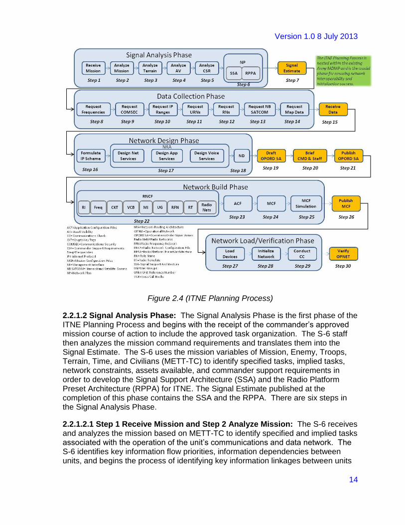
2.2.1.1 The Planning Process: The Planning Process of ITNE Signal Operations involves five phases that cover all activity required by the S-6 staff. This includes everything from the receipt of their commander’s operations order to the verification that the commander’s network is initialized and fully operational. The five Planning Process phases include the Planning Analysis Phase, the Data Collection Phase, the Network Design Phase, the Network Build Phase, and the Network Load/Verification Phase. In total, these five phases include thirty separate steps that must be performed to standard by the appropriately trained Soldier skill set. Failure to follow the steps correctly can easily result in planning mistakes that create capability gaps in the network design and/or flawed ITNE data synchronization across all devices. Minimally, these failures will result in certain incorrectly planned devices from initializing. In extreme cases, the entire ITNE can fail to initialize. Figure 2.4 below illustrates the ITNE Planning Process with all subordinate phases and steps identified.
Version 1.0 8 July 2013
14
Figure 2.4 (ITNE Planning Process)
2.2.1.2 Signal Analysis Phase: The Signal Analysis Phase is the first phase of the ITNE Planning Process and begins with the receipt of the commander’s approved mission course of action to include the approved task organization. The S-6 staff then analyzes the mission command requirements and translates them into the Signal Estimate. The S-6 uses the mission variables of Mission, Enemy, Troops, Terrain, Time, and Civilians (METT-TC) to identify specified tasks, implied tasks, network constraints, assets available, and commander support requirements in order to develop the Signal Support Architecture (SSA) and the Radio Platform Preset Architecture (RPPA) for ITNE. The Signal Estimate published at the completion of this phase contains the SSA and the RPPA. There are six steps in the Signal Analysis Phase.
2.2.1.2.1 Step 1 Receive Mission and Step 2 Analyze Mission: The S-6 receives and analyzes the mission based on METT-TC to identify specified and implied tasks associated with the operation of the unit’s communications and data network. The S-6 identifies key information flow priorities, information dependencies between units, and begins the process of identifying key information linkages between units

Version 1.0 8 July 2013
15
throughout the course of the mission. These information exchanges are a key piece of building the later Network Plan. At the completion of steps 1 and 2, the S-6 staff should have a clear information flow diagram highlighting the commander’s information exchange requirements.
2.2.1.2.2 Step 3 Analyze Terrain: The S-6 coordinates with the Battalion S-2 and S-3 to identify any/all terrain and environmental constraints that can impact the performance of the unit’s communications and data network. These constraints may include but are not limited to manmade obstructions (buildings, power lines, and communications towers), natural terrain effects (elevation and vegetation), atmospheric effects (humidity, solar flares, and precipitation), and geologic effects (magnetic resonance). Terrain impacts may require the realignment of signal assets as well or a request for additional assets from higher headquarters. Those terrain constraints, their effects, and where they occur are noted on the mission map for further planning consideration to mitigate their effects during the Network Design Phase.
2.2.1.2.3 Step 4 Analyze Asset Availability: The S-6 coordinates with the Battalion S-4 and Property Book Officer (PBO), the Battalion S-3, and company commanders to identify all signal equipment in the unit inventory and ensure it is operational. The S-6 measures operational readiness based on the Modified Table of Organization and Equipment (MTOE), the Unit Status Report (USR), the Basis of Issue Plan (BOIP), and their Communications Status Reports (CSRs). Anticipated change/modification to the MTOE equipment is a result of applying the constraints articulated in this step. For example, there may be a need to move radios from D Co to A Co based on A Co being the main effort but only having an 80% availability rate but requiring a 100% rate for full voice communications. Terrain impacts may require the realignment of signal assets as well or a request for additional assets from higher headquarters. The S-6 should always maintain a 100% inventory of signal equipment across the battalion at all times. This should be a standard procedure with a set tactic, technique, and procedure (TTP) and not solely conducted as a step in the ITNE Planning Process. In this way, the information is readily available during the planning process and does not need to be started from scratch within tight mission planning timelines. Depending on METT-TC, the S-6 may need to consider Joint, Coalition, Allied, and Host Nation asset availability.
2.2.1.2.4 Step 5 Analyze Commander Support Requirements: The S-6, leveraging the information exchange requirements and information flow diagram designed in step 1 and 2 above, determines the means to satisfy those information exchanges with both organic and supporting signal assets. These assets can range across the Joint, Allied, Coalition, Host Nation, and Interagency spectrum based on METT-TC. The assets can be both physical in nature (other transport networks) and service oriented (software based applications available over a particular transport network). Services may include but are not limited to voice, data, imagery, and video. The transport networks and services identified must match easily to the information flow diagram captured in steps 1 and 2 above as

Version 1.0 8 July 2013
16
key enablers of those information exchange priorities. ITNE NMS will need to run a simulation of the Information Flow Diagram and the equipment changes derived from step 3 and 4 to ensure the commander’s information flow requirements as defined in the information flow diagram are still achievable.
2.2.1.2.5 Step 6 Signal System Architecture (SSA) and Radio Platform Preset Architecture (RPPA): The S-6 integrates mission, terrain, asset availability, and commander support requirements through the creation of the Signal System Architecture (SSA) and the Radio Platform Preset Architecture (RPPA). The SSA is nothing more than a connectivity diagram illustrating the signal asset overlay on the approved unit task organization structure. The SSA includes all appropriate signal assets identified in step 4 and step 5. In the near term, the SSA is produced manually with tools such as PowerPoint and/or Visio. In the mid to long term, the ITNE NetOps Management System will provide the S-6 the ability to conduct the Signal Analysis Phase with more automated over the network features. The RPPA is the extraction of information from the SSA into specific configurations for each battalion ITNE network in the lower and mid tier. In order to develop the RPPA from the SSA, the S-6 must create the ITNE networks list (a listing of all networks across all units) in order to properly assign each ITNE asset to a network in the RPPA. In the near term (CS 13/14), the creation of these preset designs can be as simple as writing them out in a word processing program or directly entering them into an Excel spreadsheet as is currently performed with the J-TNT highlighted in Appendix I. In the mid to long term (CS 15 and beyond), the creation of the RPPA will be tied to the creation of the SSA through the more automated and over the network enabled ITNE NetOps management system. The completion of the SSA and the RPPA results in the Network Plan (NP). The NP is the combined architecture covering all ITNE component capabilities.
2.2.1.2.6 Step 7 Signal Estimate: The S-6 takes all of the analysis information collected in steps 1 through 4 resulting in the NP (SSA and RPPA) and drafts a unit Signal Estimate as part of the overall battalion staffing process. The Signal Estimate is briefed to the commander and published upon their approval according to standard MDMP procedures. By publishing the Signal Estimate, the Battalion S-6 provides the Battalion staff and subordinate commanders a signal support warning order that identifies signal equipment and confirms their operational status to meet the commander’s mission command needs.
2.2.1.3 Data Collection Phase: The Data Collection Phase is the second phase of the ITNE Planning Process and begins with the publication and availability of the approved Signal Estimate and is completed when the S-6 receives all requested data associated with the Signal Estimate required to build the detailed unit network design. There are eight steps in the Data Collection Phase.
2.2.1.3.1 Step 8 Request Frequencies: The BN spectrum manager (SM) submits a spectrum resources request through the BDE SM to the frequency assignment authority in accordance with current policies and regulations for all networks by type

Version 1.0 8 July 2013
17
and quantity (e.g. SRW, SINCGARS, and ANW2). In the near term (CS 13/14), the battalion spectrum manager submits a written frequency request to the brigade spectrum manager. In the mid to long term (CS 15 and beyond), the battalion S-6 can submit an automated, over the air, frequency request to the battalion spectrum manager via ITNE NMS.
2.2.1.3.2 Step 9 Request Cryptographic Key Materiel: The S-6 submits a cryptographic key materiel request to the appropriate agency or controlling authority in accordance with current policies and regulations for networked equipment and devices by type (e.g. radio platforms, ancillary devices (tactical routers and cross domain solutions)). In the near term (CS 13/14), the Battalion S-6 submits a written cryptographic key materiel request to brigade. In the mid to long term (CS 15 and beyond), the Battalion S-6 can submit an automated, over the air, cryptographic key materiel request to the brigade via the ITNE NMS based on the allowances in the BCT operations order. Brigade would then consolidate the battalions request and send it through the Key Management Infrastructure (KMI).
2.2.1.3.3 Step 10 Request Internet Protocol (IP) Ranges: The S-6 submits a request for IP ranges to the issuing agency or controlling authority in accordance with current policies and regulations that identifies all the IP networks (quantity of IP devices per network) in the Signal Estimate. The request must also include spares to compensate for continually changing mission requirements. In the near term (CS 13/14), IP ranges are assigned to the battalion by the Assistant Secretary of the Army for Acquisition, Logistics, and Technology (ASA(ALT)) based on the battalion’s Basis of Issue (BOI) to include the allocation of spares. In the mid to long term (CS 15 and beyond), the Battalion S-6 can submit an automated, over the air, IP request to the issuing agency or controlling authority via the ITNE NMS based on the allowances in the BCT operations order. This step only occurs when a task org outside the MTOE organic units occur or a commander adds additional logical nets that require the additional data elements.
2.2.1.3.4 Step 11 Request Unit Reference Numbers (URNs): The S-6 submits a request for appropriate URNs to the issuing agency or controlling authority in accordance with current policies and regulations. The URN is a unique, numerical identifier assigned to and required by each software-defined radio for situational awareness reporting. The request must also include spares to compensate for continually changing mission requirements. In the near term (CS 13/14), URNs are assigned to the battalion by ASA (ALT) based on the battalion’s BOI to include the allocation of spares. In the mid to long term (CS 15 and beyond), the Battalion S-6 can submit an automated, over the air, request to the issuing agency or controlling authority via the ITNE NMS in order to change, modify, or create new URNs based on the allowances in the BCT operations order. This step only occurs when a task org outside the MTOE organic units occur or a commander adds additional logical nets that require the additional data elements.
2.2.1.3.5 Step 12 Request Role Names (RNs): The S-6 submits a role name

Version 1.0 8 July 2013
18
request to the issuing agency or controlling authority in accordance with current policies and regulations based on the title and position of each user per radio platform in the Signal Estimate. The RN identifies and associates a Soldier to each respective radio platform. The request must also include spares to compensate for continually changing mission requirements. In the near term (CS 13/14), role names are assigned to the battalion by ASA (ALT) based on the battalion’s BOI and MTOE to include the allocation of spares. In the mid to long term (CS 15 and beyond), the Battalion S-6 can submit an automated, over the air, role name request to the issuing agency or controlling authority via the ITNE NMS in order to change, modify, or create new RNs based on the allowances in the BCT operations order. This step only occurs when a task org outside the MTOE organic units occur or a commander adds additional logical nets that require the additional data elements.
2.2.1.3.6 Step 13 Request Narrowband Satellite Communications (SATCOM): The S-6 submits a narrowband satellite access request (SAR) to the issuing agency or controlling authority in accordance with current policies and regulations for all narrowband SATCOM networks captured in the Signal Estimate. In the near term (CS 13/14), the Battalion S-6 submits a written SAR to the brigade spectrum manager. In the mid to long term (CS 15 and beyond), the Battalion S-6 can submit an automated, over the air, SAR directly to the issuing agency or controlling authority via the ITNE NMS based on the allowances specified in the BCT operations order.
2.2.1.3.7 Step 14 Request Map Data: The S-6 submits a map data request to the issuing agency or controlling authority in accordance with current policies and regulations for the mission area of operations. The request must also include map data for anticipated areas of operation in order to plan for potential changes in mission location within the overall area of operations. In the near term (CS 13/14), the Battalion S-6, in coordination with the Battalion S-2 and S-3, submits an automated map data request via the Digital Topographic Support System (DTSS) to the BCT. In the mid to long term (CS 15 and beyond), the BattalionS-6 can submit an automated, over the air, map data request directly to the issuing agency or controlling authority via the ITNE NMS based on the allowances in the BCT operations order.
2.2.1.3.8 Step 15 Receive Data: The S-6 receives all or a portion of the requested ITNE data throughout the Data Collection Phase. The S-6 prepares that data for inclusion in the Network Design Phase. When the S-6 does not receive all of the data requested, the staff must work those portions of the Signal Analysis Phase to determine the impact and make necessary changes to the NP (SSA and/or RPPA). These products, once changed, must be approved by the commander and the Signal Estimate will need to be updated and republished with the approved changes. In the near term (CS 13/14), the Battalion S-6 receives frequencies, narrowband SATCOM, and COMSEC from the BCT. The Battalion S-6 receives Data Products, a collection of communications data required to initialize Battle Command and other Army Command, Control, Communications, Computers,

Version 1.0 8 July 2013
19
Intelligence, Surveillance, and Reconnaissance (C4ISR) systems, from ASA(ALT). The Data Products enable end-to-end network centric connectivity and interoperability across the ITNE. However, the Data Products provide minimum organic flexibility to modify the ITNE to meet continually changing mission requirements. In the mid to long term (CS 15 and beyond), the Battalion S-6 can directly receive ITNE data products in an automated over the air capability via the ITNE NMS based on the allowances specified in the BCT operations order.
2.2.1.4 Network Design Phase: The Network Design Phase is the third phase of the ITNE Planning Process and begins once all the requested network data is received and the impact to any request denials are fully vetted and approved by the commander and published in a final Signal Estimate. Using the received ITNE data, the Battalion S-6 formulates an IP scheme and a Network Routing Architecture (NRA). The Battalion S-6 then finalizes the SSA and the RPPA by applying the IP scheme, network routing architecture, frequencies, narrowband SATCOM, and COMSEC data. The completion of this phase is a published Signal Annex to the battalion operations order that establishes the ITNE Network Design (ND). There are six steps in the Network Design Phase.
2.2.1.4.1 Step 16 Formulate the Internet Protocol (IP) Scheme: The S-6 creates the IP scheme based on received IP ranges to support the Signal Estimate. In the near term (CS 13/14), the battalion’s IP scheme is developed and provided by ASA(ALT) with IP ranges sub netted and assigned to unit ITNE network devices as part of the capability set fielding process. In the mid to long term (CS 15 and beyond), the S-6 can automatically subnet and assign the received IP ranges to the Network Plan (NP) via the ITNE NMS. The battalion will always receive a baseline set of IP addresses as part of the unit reset process. The baseline IP range should include spares that cover the full operational range of task reorganization, new equipment fielding, and unit specific IP address needs. These IP numbers are not doctrinally defined in the Current Force. The S-6 must take extra care to voice their needs through unit planning conferences with ASA(ALT) until a doctrinal range of IP is established.
2.2.1.4.2 Step 17 Formulate the Network Routing Architecture (NRA): The Network Routing Architecture maps the Network Plan to the required technical configurations necessary to create a network architecture for the transmission of information (voice, video, and data). The NRA translates your high-level design into a detailed design by developing the low-level network parameters for network services, application services and voice services into a configurable templates, logical and physical topology diagrams, and checklists. Planners identify interoperability, compatibility, and supportability requirements and assess them against documented capabilities, identifying any shortfalls or deficiencies for operational and mission impact.
Network Services enable the network to provide, maintain, and maximize network connectivity for all users and devices. Network Services include the following:

Version 1.0 8 July 2013
20
managing all signal support interfaces with joint and multinational forces, including host nation support interfaces; coordinating, updating, and disseminating the command operating frequencies lists; managing communications protocols, and coordinating user interfaces of defense information system networks (DISNs) and command and control systems down to battalion tactical networks; ensuring redundant signal means are available to pass time-sensitive battle command information from collectors to processors and between medical units and supporting medical laboratories; planning the detailed network design based on frequency, topology, protocol, bandwidth allocation, systems resources, applications and access to DISN services. Network Services planning provide the functionality required to enable systems, user or applications to support data distribution, message services, and access to necessary information within and across the mission area of operations. Some common network services include: directory services, E-mail, file sharing, gateway services (lower & mid tier connectivity; joint & multinational connectivity), waveform chat services, printing, Voice over IP, video on demand, and network management services.
Application Services provide remote access to application programs across tactical networks. Application Services are a secure and efficient way of integrating applications over IP based networks to increase availability of the application. These services provide secure C2 and intelligence information to Soldiers within the ITNE through accessing the mission command application using a thin client on mobile devices. TIGR is an example of an application service which provides intelligence information to Soldiers from a server accessed over an IP based network using a thin client.
Voice Services include the traditional combat network radio (CNR) and application based voice services such as Voice over Internet Protocol (VoIP). The CNR network’s primary role is voice transmission for Command and Control. The CNR network assumes a secondary role for data transmission when requirements exceed the Army Data Distribution System or WIN-T capabilities. Voice C2 information maintains priority over data in most networks. The exception is using SINCGARS with the Tactical Fire Direction System or Advanced Field Artillery Tactical Data Systems (AFATDS). Current demands on voice C2 networks require a large amount of operational time. This leaves little time for data sharing. VoIP is a methodology and group of technologies for the delivery of voice communications and multimedia sessions over Internet Protocol (IP) networks, such as the Internet. Other terms commonly associated with VoIP are IP telephony, Internet telephony, voice over broadband (VoBB), broadband telephony, IP communications, and broadband phone service.
2.2.1.4.3 Step 18 Finalize the Network Design (ND): The S-6 applies the IP scheme, the Network Routing Architecture, frequencies, narrowband SATCOM, and COMSEC data to the Network Plan to complete the detailed Network Design (ND). In the near term (CS 13/14), the Battalion S-6 manually applies the data to the Network Plan. In the mid to long term (CS 15 and beyond), the Battalion S-6 can

Version 1.0 8 July 2013
21
automatically apply the data to the Network Plan via the ITNE NMS. The creation of the ND marks a transition point between the “art of war” in the first three phases of the ITNE Planning Process to the “science of war” in the last two phases. In many ways, the handoff from the S-6 leadership to the S-6 operators occurs at this point.
2.2.1.4.4 Step 19-21 Draft, Brief, and Publish the Signal Annex (SA): The S-6 utilizes the examples specified in Appendix E (Army Operation Plan and Order Format) of FM 5.0 (The Operations Process) to draft the Operations Order Signal Annex from the Signal Estimate and the Network Design. After briefing the Command and Staff and receiving commander approval, the S-6 publishes the Signal Annex to the battalion in order to initiate the Network Build Phase. In the near term (CS 13/14), the Battalion S-6 manually creates the Signal Annex. In the mid to long term (CS 15 and beyond), the Battalion S-6 can automatically generate the Signal Annex from the ITNE NMS utilizing the information already captured during the first three phases of the ITNE Planning Process.
2.2.1.5 Network Build Phase: The Network Build Phase is the fourth phase of the ITNE Planning Process. In this phase, the S-6 uses the Network Design from the previous phase and builds the Radio Network Configuration File (RNCF) and Application Configuration File (ACF). With the completion of these two products, the Battalion S-6 now has the ITNE Mission Configuration File (MCF). The MCF includes all network device and application configuration files required to implement and execute the battalion’s mission network. In the near term (CS 13/14), the Battalion S-6 then manually tests and validates the MCF through direct access and observation. In the mid to long term (CS 15 and beyond), the S-6 utilizes simulation tools built into the ITNE NMS. The end state of this phase is the manual and/or automated distribution of the MCF to all battalion units in support of follow-on Network Load/Verification Phase operations. The completion of this phase is a published MCF. There are five steps in the Network Design Phase.
2.2.1.5.1 Step 22 Build Radio Network Configuration File (RNCF): The S-6 builds the RNCF, a Microsoft Excel spreadsheet consisting of tabs with fields and columns, which is populated with radio network data from the Network Design and compiled by the ITNE NMS to produce specific radio configuration files that are later loaded onto software defined radios. The process of entering this information into the ITNE NMS is currently captured in the J-TNT new equipment training offered by the ITNE program managers. The RNCF consists of the following tabs:
Radio Inventory (RI): The RI is comprised of each software-defined radio with radio type (AN/PRC-154, AN/PRC-117, etc), attributes, and network settings from the Network Design.
Frequencies (Freq): The Freq is composed of each radio network by name with assigned frequency from the Network Design.

Version 1.0 8 July 2013
22
Crypto Key Tags (CKT): CKT is comprised of radio network types (e.g. SRW, SINCGARS, etc) by security classification with assigned cryptographic data from the Network Design.
Voice Call Books (VCB): VCB identifies voice calls for use under SRW networks utilizing Combat Net Radio (CNR) voice traffic by specific voice call names (e.g. BDE CMD, BN CMD, BN FSC and ACO CMD) assigned to generalized voice call names (BDE, BN, CO, etc) from the Network Design.
Management Interface (MI): MI is comprised of the username and passphrases for role-based ITNE NMS users (e.g. Administrator, Security Officer, Operator, etc) by specific radio vendor (e.g. HMS, Harris, ITT) for authentication under Simple Network Management Protocol (SNMP) communication between radios and ITNE NMS.
User Groups (UG): UG is comprised of assignments of role-based ITNE NMS users (e.g. Administrator, Security Officer, Operator, etc) to radio types (Manpack, Rifleman, etc) by vendor (e.g. HMS).
Radio Frequency Networks (RFN): RFN comprises each radio network by name with network type (SRW, SINCGARS, narrowband SATCOM, etc) with all underlying characteristics such as frequency, IP address, crypto tags, etc. from the Network Design. Examples include the following:
Radio Template (RT): The RT is a listing of all radio platform data organized under specific vendors with all possible preset assignments. An example of a current RT is as follows: One separate tab within an Excel spreadsheet for each vendor (HMS, F3MP/Harris, and ITT). Each tab includes all presets from the Network Design for each software-defined radio type (AN/PRC-154, AN/PRC-117, etc).
Radio Networks (RN): The RN integrates all of the pre-populated data in the RNCF and associates it to a specific user within a specific network. The RN is mapped to the RFN and RT in order to reference all specific radio platform data required for this user assignment. An example of a current RN is as follows: One separate tab within an Excel spreadsheet for each vendor (HMS, F3MP/Harris, and ITT) with each user assigned to a specific radio with specific presets.
In the near term (CS 13/14), the S-6 manually applies all ITNE data from the ND to the RNCF through direct entry on the J-TNT or through the creation of the Excel spreadsheet and importation into the J-TNT. Either way, the S-6 operator must manually enter the RNCF data into the J-TNT. The mid to long term (CS 15 and beyond), the Battalion S-6 can automatically apply the data to the RNCF via the ITNE NMS planning module.
2.2.1.5.2 Step 23 Application Configuration Files (ACF): The S-6 builds the ACF, files composed of mission command specific application data needed to map

Version 1.0 8 July 2013
23
the application to the transport layer of the radio platform, from data within the Network Design. In the near term (CS 13/14), the Battalion S-6 receives configuration files for mission command systems (e.g. JBC-P) and applications from brigade. In the mid to long term (CS 15 and beyond), the Battalion S-6 has the capability via battalion BCCS and Warfighter Initialization Tool (WIT) integrated with the ITNE NMS to automatically plan and build mission command configuration files.
2.2.1.5.3 Step 24 Mission Configuration Files (MCF): With the completion of the RNCF and ACF, the Battalion S-6 now has all the information necessary to compose the MCF. The MCF is the all inclusive package of configuration files required to load and configure ITNE network devices and mission command applications. In the near term (CS 13/14), the Battalion S-6 manually imports the RNCF portion of the MCF in to the J-TNT or enters it manually as mentioned under 2.2.1.5.1 above. The ACF files are loaded as appropriate into the End User Devices (EUDs) to ensure interoperability and connectivity with their host radio platforms. In the mid to long term (CS 15 and beyond), the MCF data will be incorporated into the integrated ITNE Planning Process via the ITNE NMS and made available in the same manner as the RNCF.
2.2.1.5.4 Step 25 MCF Simulation: The S-6 conducts a simulated test of the MCF on network simulation software to confirm that the MCF establishes the designed network to meet and support the commander’s information exchange requirements. In the near term (CS 13/14), the Battalion S-6 does not have the capability to conduct a simulation test via the J-TNT. In the mid to long term (CS 15 and beyond), the Battalion S-6 can conduct a simulation test using network simulation software on the ITNE NMS.
2.2.1.5.5 Step 26 Publish MCF: Upon confirmation of a successful MCF simulation, the S-6 creates subordinate unit specific MCFs and publishes them for use in during the Network Load/Verification Phase. In the near term (CS 13/14), the Battalion S-6 produces subordinate unit specific RNCFs via the J-TNT and publishes them manually to each unit. The ACF is published under unit specific standard operating procedures and publishes them manually to each unit. In the mid to long term (CS 15 and beyond), the Battalion S-6 can produce subordinate unit MCFs on the ITNE NMS and publish them accordingly to each subordinate unit via the ITNE NMS.
2.2.1.6 Network Load & Verification Phase: The Network Load & Verification Phase is the fifth and last phase of the ITNE Planning Process. In this phase, the S-6 and subordinate units load all mission network devices and mission command systems with their specific MCF, initialize the network, and conduct a communications check. At the end of this phase, the S-6 provides a commander approved operational network (OPNET) that meets and supports the identified information exchange requirements. There are four steps in the Network Load & Verification Phase.
Version 1.0 8 July 2013
24
2.2.1.6.1 Step 26 Load Devices: The S-6 and subordinate units load all mission network devices and mission command systems with their unit specific MCF. In the near term (CS 13/14), the Battalion S-6 and subordinate units produce a specific configuration file for each software-defined radio using the RNCF from their specific MCF, load it onto an SKL, and fill each unit owned software-defined radio with its specific configuration file. Additionally, the Battalion and S-6 load each mission command system (e.g. JBC-P) with the unit specific ACF using each system’s specific load device (e.g. Mission Data Loader). In the mid to long term (CS 15 and beyond), the Battalion S-6 and subordinate units can load all unit owned ITNE network devices and mission command systems with their unit specific MCF in a fully automated over the network process via the ITNE NMS. The manual SKL approach will still be available if required.
2.2.1.6.2 Step 27 Initialize Network: Upon completion of Step 26 - Load Devices, the Battalion S-6 and subordinate units initialize the mission network in order to determine if all network devices and mission command systems establish connectivity and are functioning properly. The Battalion S-6 has now established the mission network baseline configuration. In the near term (CS 13/14), the Battalion S-6 and subordinate units manually initialize the mission network in a prioritized and controlled manner in order to establish connectivity between network devices and mission command systems. The J-TNT can be used to verify network connectivity with its monitoring capability. In the mid to long term (CS 15 and beyond), the Battalion S-6 and subordinate units can remotely initialize the mission network and verify connectivity via the ITNE NMS.
2.2.1.6.3 Step 28 Conduct Communications Check: Upon completion of Step 27 – Initialize Network, the Battalion S-6 and subordinate units conduct communications checks to verify the network and services can support and meet the commander’s information exchange requirements. In the near term (CS 13/14), the Battalion S-6 and subordinate units test and verify all network services manually by sending voice and data traffic across the network to verify network operational readiness. In the mid to long term (CS 15 and beyond), the Battalion S-6 and subordinate units can generate traffic data to stress the network via the ITNE NMS. This will be available in addition to the current method.
2.2.1.6.4 Step 29 Verify OPNET: Upon completion of Step 28 – Conduct Communications Check, the Battalion S-6 briefs the commander on the results of the Communications Check and the battalion conducts a mission rehearsal to verify to the commander that the network supports the identified information exchange requirements. In the near term (CS 13/14), upon the commander verifying the OPNET, all subordinate units manually pass their OPNET verified MCF to the Battalion S-6 in order for battalion MCF to be current. In the mid to long term (CS 15 and beyond), subordinate units can update their MCF on their ITNE NMS which will automatically update the battalion MCF on the battalion ITNE NMS. The Verify OPNET step signals the transition between the ITNE Planning Process and the ITNE Management Process. The details of the Verify OPNET are covered below

Version 1.0 8 July 2013
25
under the Management Process section.
2.2.2 Management: Management within ITNE Signal Operations provides the S-6 staff with the means to monitor and affect ITNE component systems in real time. This requires an ability of each ITNE system to advertise key information elements to the ITNE NMS and for the ITNE NMS to collect those information elements, analyze them, and provide an overall status with regard to the information category collected.
Management is all about predictive analysis and proactive actions taken by the S-6 staff to resolve network faults, failures, and vulnerabilities prior to their realization causing a loss of network capability for the commander. Unlike the Planning Process, the Management Process is a parallel set of phases based on the International Standard Organization (ISO) telecommunications management network framework called the Fault, Configuration, Accounting, Performance, and Security (FCAPS) model.
In the near term (CS 13/14), the Management Process of ITNE signal operations is quite limited. In fact, the only monitoring capability available through the current ITNE NMS, in this case the J-TNT, is a radio monitoring feature that allows the S-6 to track whether a particular radio is on or off. The J-TNT does not provide monitoring of all ITNE devices in the near term, only the radio platforms. In the mid to long term, greater functionality and breadth of capability will be added to the ITNE NMS to ensure FCAPS tracking is robust, efficient, and reliable. True predictive analysis and proactive management will only be available in the mid to long term through the ITNE NMS. Near term predictive analysis and proactive capability is in the hands of the S-6 staff’s manual processes for trouble ticketing and reporting procedures.
2.2.2.1 The Management Process: The Management Process of ITNE Signal Operations involves four simultaneous phases that are preceded by the operational network verification step 30 from the ITNE Planning Process Network Load/Verification Phase. The Verify OPNET step is the transition point between the Planning and the Management Process. During the Verify OPNET, the S-6 initializes the MCF and allows the network to self populate the network common operational picture (NCOP). The NCOP is composed of the live depiction of the Signal Support Architecture (SSA) developed in the Planning Process along with the network specifics associated with each signal asset. This information is then reviewed for accuracy against the SSA to ensure proper initialization of the ITNE.
If the network initialized and is operational but discrepancies are found, they are handled through the Fault Management phase. If the network fails to initialize, the S-6 must troubleshoot the problem by returning to the appropriate steps of the Planning Process and isolate where the problem occurred, repair the deficiency, and then repeat the steps from the point of the failure in the Planning Process until the network does initialize through Step 30 of the Planning Process. TTPs

Version 1.0 8 July 2013
26
associated with this troubleshooting procedure are under development and will be available in the near future through the procedures identified in Appendix M of this CONOPS.
The Management Process provides the S-6 an ability to actively monitor the commander’s network to ensure hardware and software faults are identified early in the failure process and remedied prior to realization on the operational network preventing loss of capability to combat forces. Additionally, the S-6 is able to monitor performance and security matters based on the METT-TC identified in the approved commander’s operations order, ensure compliance, and correct deficiencies during operations. The S-6 uses the Administrative Management Phase to ensure version control of hardware and software, execute critical patch updates, modify role names based on task reorganization, and inform network users on radio platform preset changes while still conducting operations. This includes everything from the receipt of their commander’s operations order to the verification that the commander’s network is initialized and fully operational.
In the near term (CS 13/14), the ability for the S-6 to conduct Management Process Phases with an automated network operations management system are severely limited. In most cases, the best the S-6 can do is identify the up or down status of a particular radio via the J-TNT radio monitoring capability or receive a traditional phone call or trouble ticket and then respond with direct intervention by providing S-6 staff to work the problem. This is time consuming and cumbersome so the S-6 must plan their personnel resources according to expected failures, mission priorities, and personnel availability. In the mid to long term (CS 15 and beyond), the ITNE NMS will provide automated over the network capability to directly contact ITNE component devices and manage them in real time without the need of dispatching personnel to the site of the problem. Figure 2.5 below illustrates the ITNE Management Process with all subordinate phases and steps identified.

Version 1.0 8 July 2013
27
Figure 2.5 (ITNE Management Process)
2.2.2.1.1 Verify Operational Network (OPNET): The Verify OPNET portion of the ITNE Management Process begins with Step 30 of the ITNE Planning Process when the Network Load/Verification Phase is completed through the communications check process and ends when the S-6 validates that the MCF meets the information flow requirements of the commander established in the Signal Analysis Phase of the ITNE Planning Process. This is accomplished by comparing the DSSA and the DNS to the actual NCOP populated in the Verify OPNET process. Once the NCOP and DSSA and DNS are validated, the MCF is valid and the ITNE is fully initialized and ready for mission command operations. There are three steps in the Verify OPNET process.
2.2.2.1.1.1 Step 1 (Discover Signal Support Architecture): The SSA provides the operational commander with command and control of their organic and assigned signal assets during combat operations and supports the information flow requirements established by the commander to meet mission objectives. The DSSA is the process by which the S-6 populates the NCOP through the collection of all ITNE device status messages. In the near term (CS 13/14), the S-6 has the ability to discover the signal support architecture but it is not integrated in to one common picture. In the mid to long term (CS 15 and beyond), the ITNE NMS will provide an automatic discovery process for all IP addressed network devices and populate the corresponding SSA into one NCOP.
2.2.2.1.1.2 Step 2 (Discover Network Specifics): The DNS provides the S-6 with

Version 1.0 8 July 2013
28
the ability to visualize and monitor all the detailed data associated with each networked ITNE device populated in the DSSA/NCOP. The DNS completes the overall NCOP when combined with the DSSA and allows the S-6 to check on key network functionality such as link state, inter node connectivity, and routing design. These are compared to the information flow diagrams in the NP to verify that the network specifics are properly configured to support the flow of mission command voice and data as directed by the commander. Where discrepancies and/or issues are identified, the S-6 must make immediate modifications to match the NP and ND. In the near term (CS 13/14), the ability to perform auto discovery of the network specifics is limited to manual collection and is therefore of little use in validating the NP and ND against the MCF. The time factors to complete this task manually are not compatible with most operations. For the mid and long term (CS 15 and beyond), the ITNE NMS will automatically populate and display the DSSA and DNS in real time to quickly validate the MCF and complete the Verify OPNET process.
2.2.2.1.1.3 Step 3 (Validate Mission Configuration File): The MCF validation is an essential step in completing network initialization and operation. The MCF validation is the last chance the S-6 has to catch and resolve problems before they impact mission command users. As previously stated, the MCF validation requires the S-6 to compare the DSSA and DNS against the NP and ND. If properly validated, the S-6 ensures the commander’s key information exchanges and prioritization are enabled through the MCF. The full automated processing of these comparisons will only be available in the mid to long term (CS 15 and beyond) ITNE NMS.
Once Validate MCF is complete, the network is mission command capable. This is where the S-6 monitoring mission begins within the ITNE Management Process. Monitoring involves four simultaneous phases that provide the ability to detect, isolate, analyze, and remedy all ITNE component issues on the live network. These phases include Fault Management, Administrative Management, Performance Management, and Security Management.
2.2.2.1.2 Fault Management Phase: The Fault Management Phase provides for the detection, isolation and resolution of network problems. The S-6 utilizes the Fault Management Phase as an active listening capability on all ITNE networked devices. This capability is configurable based on parameters established through the S-6. These parameters are based on the commander’s primary concerns which once again link to the information flow diagram developed early in the ITNE Planning Process. The S-6 will focus monitoring on interoperability nodes, crossbanding locations, Battalion interconnectivity, communication with higher and attached units, and quality of service performance. There are six steps in the Fault Management Phase.
2.2.2.1.2.1 F-Step 1 Detect Fault (DF): The DF Step is designed to monitor all ITNE component systems based on METT-TC priorities and identify when a fault has occurred or is in the process of occurring. The objective is to pinpoint the type

Version 1.0 8 July 2013
29
of fault and its location. In the near term (CS 13/14), the ability to automatically detect faults does not exist. Near term capabilities are primarily manual in nature and based on a reactive approach – trouble ticketing and voice calls. In the mid to long term (CS 15 and beyond), the Battalion S-6 will utilize the capability within the ITNE NMS to recognize faults and pinpoint their location through an automated over the network alert function. This allows the S-6 to establish a proactive instead of a reactive approach to real time ITNE network issues. 2.2.2.1.2.2 F-Step 2 Isolate Fault (IF): The Isolate Fault Step pinpoints the exact cause and location of a problem. This begins the process of determining what might have caused the fault through the isolation of variables directly linked to the failure and the removal of those that were not linked. The S-6 will conduct fault isolation in the near, mid, and long term utilizing the same process. The staff must assess the concern and the priority the problem is afforded. The S-6 must discover all information related to the fault such as event logs, network analysis, and network activity information in order to isolate the problem. The staff will need to justify the cause of the fault and analyze the information found in discovery to suggest an approach that facilitates a comprehensive diagnostic.
2.2.2.1.2.3 F-Step 3 Conduct Fault Diagnostic (CFD): The Conduct Fault Diagnostic Step consists of a determination of the fault type to include as many details as possible that will aid in the identification of the fault and the reason for the failure (e.g. fault size, location and time of detections). The range of diagnostics in nearly limitless as the potential number and type of faults within the ITNE are broad and constantly changing as the technology matures. In the near term (CS 13/14), the Battalion S-6 is limited to primarily a manual fault diagnostic process based on the diligent recording and processing of fault occurrences and the subsequent research and application of solutions. In the mid to long term (CS 15 and beyond), the ITNE NMS will conduct real time over the network automated processes to run quickly and efficiently determine the nature of a fault within the ITNE NMS data collection parameters. Once complete, the S-6 is able to establish the IFRC.
2.2.2.1.2.4 F-Step 4 Identify Fault Root Cause (IFRC): The Identify Fault Root Cause Step is the compilation of the analysis involved in the previous steps where the network data collected in relation to the fault along with the isolation of the fault provides a reasonable estimation of the fault’s primary cause. This process is similar to a course of action analysis where options are eliminated based on the facts, assumptions, and measuring criteria. The intent is to correctly identify the root cause and deal not only with the symptoms. The means to avoid this pit fall is to ensure the measuring criteria is accurate, based on experience, and measurable. In the near term (CS 13/14), the ability to identify fault root cause is limited to manual approaches within existing staff processes. The S-6 trouble ticketing and voice call procedures under Fault Management must be established in an SOP and updated regularly based on each mission and succession of documented faults. Only in this way can an S-6 staff rapidly respond to faults. In the mid to long term (CS 15 and beyond), the Battalion S-6 will utilize the ITNE NMS automated
Version 1.0 8 July 2013
30
procedures for the assessment of IFRC. Whether manual or automatic in nature, root cause analysis as part of the IFRC must be performed systematically, usually as part of an investigation, with conclusions and root causes that are identified and backed up by historic data and SOPs.
2.2.2.1.2.5 F-Step 5 Determine Solution (DS): The Determine Solution Step is simply the process of applying both technical and operational knowledge to specifying a solution to an identified fault. When determining a particular fault solution, S-6 must focus on the positive and negative consequences of both action and inaction. In some cases, the S-6 may need to act to remedy the problem but in others in may make more sense to accept the fault until a later point in time. This is usually the case when the fault is minor, of little impact, and to remedy the problem would introduce more risk than applying the solution. The S-6 will select a solution by following the 5 aspects of Dependability: Availability, Reliability, Safety, Security, and Maintainability. The system must have the ability to be repaired. In the near term (CS 13/14), the Battalion S-6 performs this function with limited resources. These are primarily through the unit SOP, ITNE TTPs, and immediate action drills and/or repairs rendered through the trouble ticketing process. In the mid to long term (CS 15 and beyond), the ITNE NMS will provide the ability to directly connect to ITNE devices over the network and affect repairs in real time.
2.2.2.1.2.6 F-Step 6 Trend Analysis/Archiving (TA/A): The Trend Analysis/Archiving Step involves the process of recording and analyzing faults over time. The recording and trend analysis within the ITNE Management Process is for short duration usage. The S-6, during operations, is required to assess trends that occur over hours and days and not just the traditional long term analysis that occurs over months and years. The short duration analysis assists the S-6 in optimizing their operational mission command network while it is in fact operational. The long duration analysis is designed to assess more severe cross mission issues and is not designed for immediate action. These TAs make up the remaining process of ITNE Signal Operations called the ITNE Analysis Phase and are designed to provide optimization through modification of the ITNE Planning and Management Processes. In the near term (CS 13/14), the S-6 does not conduct TA/A during operations. The S-6 is limited to trouble ticketing and voice calls. The S-6 is able to conduct the longer term cross mission TA/As through the standard After Action Report process as part of the unit staff. In the mid to long term (CS 15 and beyond), the S-6 will utilize their ITNE NMS to proper electronically capture all the required data during operations to conduct real time trend analysis and apply predictive analysis to planning and managing the ITNE.
2.2.2.1.2.7 F-Step 7 Execute Restoration (ER): The Execute Restoration Step of the Fault Management Phase ensures that all identified faults are properly addressed and remedied in accordance with network priorities of service. In the near term (CS 13/14), these remedies are performed by S-6 staff directly or over the voice network and/or by the General Purpose User (GPU) based on the technical complexity and severity of the fault. In the mid to long term (CS 15 and

Version 1.0 8 July 2013
31
beyond), the S-6 will utilize the ITNE NMS to push remedies and restoration services to the network device. In extreme cases of network degradation, the ITNE NMS will use the information gathered from F-Steps 1 thru 6 to build an executable restoration plan that will execute quickly, reliably, and with precision. The restore feature provides an important safeguard to help protect the network.
2.2.2.1.3 Administrative Management Phase: The Administrative Management Phase of the ITNE Management Process includes those functions that add, change, modify, delete, and/or update administrative information within the MCF. The cause for these administrative changes are as simple as adding a new Soldier or as complex as executing a unit task reorganization (UTR). The details of the UTR are defined in Appendix K of this CONOPS. Administrative Management includes. but is not limited, to some of the following common functions: management of authorized users by establishing names, passwords, roles, and permissions with a user based login policy; performing systems software backup, updates, and synchronization; and executing UTRs. In the near term (CS 13/14), functions within the Administrative Management Phase are performed across a range of systems by different Soldiers within the BCT S-6 and Battalion S-6. In the mid to long term (CS 15 and beyond), the Battalion S-6 will utilize the ITNE NMS to manage all of these functions within the battalion’s organic and attached network. Likewise, the BCT S-6 will manage their BCT organic and attached network resources with the ITNE NMS. There are six steps in the Administrative Management Phase.
2.2.2.1.3.1 A-Step 1 Component Updates (CU): The Component Update Step of the Administrative Management Phase allows the S-6 to conduct live updates to hardware and/or software across the range of ITNE component devices. There are two types of component updates. The first is a planned update that is usually received from the Program Manager of the device. Component updates can be received from other sources such as higher headquarters, a vendor, or a third party (Allied Force or Service Component) based on METT-TC circumstances. The second is an unplanned update that is usually due to a component failure. This requires some form of a reset, repair, or replacement. The S-6 must distinguish between components that can be upgraded by someone who is not a network professional and those that require installation by a trained technician. In the near term (CS 13/14), updates are performed manually. In the mid to long term (CS 15 and beyond), the ITNE NMS will provide the ability to automatically update ITNE components during live network operations.
2.2.2.1.3.2 A-Step 2 Asset Distribution (AD): The Asset Distribution Step of the Administrative Management Phase allows the S-6 to ensure the appropriate distribution of Signal assets across the network. The intent is to ensure the most effective and efficient use of network resources in accordance with the SSA to minimize loss of connectivity and maximize data flow. The S-6 staff must maintain accountability of Signal assets at all times. The AD Step ensures the appropriate real time over the network alignment between the SSA and the MCF. In the near

Version 1.0 8 July 2013
32
term (CS 13/14), the AD Step is performed manually with standard office tools and focused staff work. In the mid to long term (CS 15 and beyond), the ITNE NMS will bring an automated tool that provides real time management of all ITNE component devices.
2.2.2.1.3.3 A-Step 3 Role Name Modification (RNM): The Role Name Modification Step of the Administrative Management Phase identifies and associates a Soldier to each respective radio platform. This is done as an immediate change during operations to account for minor or major changes to the unit task organization (UTO) caused by METT-TC circumstances. In the near term (CS 13/14), the S-6 executes these changes at the BCT level with the Warfighter Initialization Tool (WIT). The WIT only modifies Mounted/Mobile Mission Command Application Component data at the BCT level. The ITNE transport and networking layer data is handled through the J-TNT as part of the ITNE Planning Process. In the mid to long term (CS 15 and beyond), the S-6 will utilize the ITNE NMS to update all ITNE component data across application, networking, and transport layers of the network in an integrated and coherent manner both within the ITNE Planning Process and during live operations as an aspect of the RNM Step of the ITNE Management Process.
2.2.2.1.3.4 A-Step 4 Radio Platform Preset Change (RPC): The Radio Platform Preset Change Step of the ITNE Administrative Management Phase provides the S-6 with the ability to automatically alert all personnel and devices within the ITNE to execute a preset change. This occurs when the S-6 is ordered by the commander to move to another preset based on METT-TC. The S-6 sends a digital alert to all affected personnel to change from the existing preset to a designated preset. All relevant information is included in the alert to ensure 100% compliance of all personnel. The RPC can also be sent to a smart ITNE device which then executes the change according to the presets available and the direction of the alert. In the near term (CS 14/14), the S-6 does not possess an automated over the network capability for RPC. RPC is executed either by voice command or messaging alerts. In the mid to long term (CS 15 and beyond), the ITNE NMS will provide automated capabilities as identified above.
2.2.1.3.5 A-Step 5 Trend Analysis/Archiving: The Trend Analysis/Archiving Step of the Administrative Management Phase is used to track variances and or efficiencies regarding ITNE component asset performance. The S-6 combines the collected performance data across a specified period of time based on METT-TC. This is used to determine the asset utilization methodologies. In the near term (CS 13/14), the S-6 TA/A is manual. The S-6 must review report logs after the mission and compare the data through the manual correlation of disparate data reports. This is cumbersome and time consuming and therefore rarely performed. In the mid to long term (CS 15 and beyond), the S-6 will utilize the ITNE NMS to conduct automated correlation of performance data across any/all ITNE devices to ensure asset performance matches the mission need. This information is displayed in the NCOP as a live TA/A report. If performance data does not match required

Version 1.0 8 July 2013
33
thresholds, then the S-6 executes the Fault Management Phase steps to determine the cause and execute a restoration of service or conducts procedures within the Performance Management Phase to modify the configuration of the affected device/s to improve performance.
2.2.2.1.3.6 A-Step 6 Execute Administrative Changes: The Execute Administrative Changes Step of the Administrative Management Phase enables the S-6 to automatically add, change, modify, delete, and/or update administrative data as outlined under 2.2.2.1.3 above based on METT-TC. The near term (CS 13/14) and mid to long term (CS 15 and beyond) capabilities are as outlined in that paragraph as well.
2.2.2.1.4 Performance Management Phase: The Performance Management Phase of the ITNE Management Process consists of measuring and optimizing the network to ensure it can support the flow of voice and data traffic according to the quality of service priorities established by the commander. Performance management offers a foundation for pro-active management of ITNE component devices. In the near term (CS 13/14), performance management is extremely limited. Most current ITNE performance management functionality is in reality more a Fault Management Phase functionality where a problem is identified and resolved. In the mid to long term (CS 15 and beyond), the ITNE NMS will provide performance management features that allow the measuring and modification of all ITNE component devices. This will include the ability to measure packet loss/completion, node link state, bandwidth consumption, route congestion, and other key performance metrics that enable real time adjustment to the flow of voice and data across the ITNE via the modification of ITNE component settings. There are four steps in the Performance Management Phase.
2.2.2.1.4.1 P-Step 1 Monitor Parameters (MP): The Monitor Performance Step of the Performance Management Phase provides the S-6 with the ability to directly track the metrics of all ITNE component devices in real time. Monitoring parameters include such features as providing a filterable data collection polling process, automated analysis based on preset formulas, performance threshold alerting, and reporting capabilities for all ITNE components or sets of components. In the near term (CS 13/14), there are multiple tools performing this function. All of them are severely limited and don’t provide a feature to tailor, filter, or establish preset formulas for performance metric measuring and threshold settings. In the mid to long term (CS 15 and beyond), the S-6 will utilize the ITNE NMS to receive, manage, and view real-time performance metric alert messages based on the configuration, filters, and settings preferred by the S-6 on the NCOP.
2.2.2.1.4.2 P-Step 2 Conduct Diagnostic (CD): The Conduct Diagnostic Step of the Performance Management Phase enables the S-6 to review all available/collected performance metrics, correlate the data, and determine the reason for performance failures/deficiencies. The CD Step will include performance tests for IP configurations, default gateways, security settings, routing connectivity,

Version 1.0 8 July 2013
34
and other performance related assessments. In the near term (CS 13/14), the S-6 has limited capabilities to perform diagnostics on ITNE component devices. Once again, performance management is conducted after the fact through the Fault Management Phase steps. In the mid to long term (CS 15 and beyond), the ITNE NMS will provide a performance management capability that enables real time over the network diagnostics of ITNE component devices.
2.2.2.1.4.3 P-Step 3 Trend Analysis/Archiving (TA/A): The Trend Analysis/Archiving Step of the Performance Management Phase is used to track variances and or efficiencies regarding ITNE component device performance. The S-6 combines the collected performance data across a specified period of time based on METT-TC. This is used to determine the asset utilization methodologies. In the near term (CS 13/14), the S-6 TA/A is manual. The S-6 must review report logs after the mission and compare the data through the manual correlation of disparate data reports. This is cumbersome and time consuming and therefore rarely performed. In the mid to long term (CS 15 and beyond), the S-6 will utilize the ITNE NMS to conduct automated correlation of performance data across any/all ITNE devices to ensure asset performance matches the mission need. This information is displayed in the NCOP as a live TA/A report. If performance data does not match required thresholds, then the S-6 executes the Fault Management Phase steps to determine the cause and execute a restoration of service or executes performance changes in accordance with the Performance Management Phase P-Step 4 procedures.
2.2.2.1.4.4 P-Step 4 Execute Performance Changes: The Execute Performance Changes Step of the Performance Management Phase enables the S-6 to automatically change and/or modify performance settings on any ITNE component device. These changes are based on the commander’s direction according to METT-TC factors. In the near term (CS 13/14), the S-6 does not possess the means to conduct real time over the network performance setting changes to all ITNE component devices. There is some ability to modify tactical routers and gateways with the existing commercial off the shelf (COTS) tools resident in the BCT NetOps toolset. At the battalion and below this capability is not available. In the mid to long term (CS 15 and beyond), the S-6 at all levels will have the ability to utilize the ITNE NMS to monitor and modify all performance settings on all ITNE devices in real time over the network.
2.2.2.1.5 Security Management Phase: The Security Management Phase of the ITNE Management Process involves all activities that the S-6 undertakes to protect ITNE component device value, usability, data integrity, and continuity of operations. The staff must effectively identify threats and then choose the most effective ITNE NMS tool to combat them. In the near term (CS 1/14), ITNE Security Management is limited to communications security (COMSEC) protections and local account login procedures. In the mid to long term (CS 15 and beyond), the ITNE NMS will provide security services that include host based and external intrusion protection and prevention capabilities. The Security Management Phase is an extension of

Version 1.0 8 July 2013
35
the Fault and Performance Management Phases for security devices within the ITNE components. There are four steps in the Security Management Phase.
2.2.2.1.6 S-Step 1 Monitor Parameters (MP): The Monitor Performance Step of the Security Management Phase provides the S-6 with the ability to directly track the metrics of all ITNE component security devices in real time. Monitoring parameters include such features as providing a filterable data collection polling process, automated analysis based on preset formulas, performance threshold alerting, and reporting capabilities for all ITNE components or sets of components. In the near term (CS 13/14), there are no tools providing this function for the ITNE. All security is performed with COMSEC and local account login. In the mid to long term (CS 15 and beyond), the S-6 will utilize the ITNE NMS to receive, manage, and view real-time security performance metric alert messages based on the configuration, filters, and settings preferred by the S-6 on the NCOP.
2.2.2.1.7 S-Step 2 Conduct Diagnostic (CD): The Conduct Diagnostic Step of the Security Management Phase enables the S-6 to review all available/collected security related performance metrics, correlate the data, and determine the reason for performance failures/deficiencies. The CD Step will include performance tests for cross domain solution settings, Internet Protocol Security Systems (IPSS), and Host based Security Systems (HBSS) configurations, and other security device performance settings. In the near term (CS 13/14), the S-6 has limited capabilities to perform diagnostics on ITNE component devices as security enabled devices are non-existent within the ITNE. Once again, only COMSEC and local login features are available. In the mid to long term (CS 15 and beyond), the ITNE NMS will provide a performance management capability that enables real time over the network diagnostics of ITNE security component devices.
2.2.2.1.8 S-Step 3 Trend Analysis/Archiving (TA/A): The Trend Analysis/Archiving Step of the Security Management Phase is used to track variances and or efficiencies regarding ITNE component security device performance. The S-6 combines the collected performance data across a specified period of time based on METT-TC. This is used to determine the asset utilization methodologies. In the near term (CS 13/14), the S-6 TA/A is manual and related only to COMSEC and local account management procedures. In the mid to long term (CS 15 and beyond), the S-6 will utilize the ITNE NMS to conduct automated correlation of security performance data across any/all ITNE security devices to ensure asset performance matches the mission need. This information is displayed in the NCOP as a live TA/A report. If performance data does not match required thresholds, then the S-6 executes the Fault Management Phase steps to determine the cause and execute a restoration of service or executes security management changes in accordance with the Security Management Phase S-Step 4 procedures.
2.2.2.1.9 S-Step 4 Execute Security Changes: The Execute Security Changes Step of the Security Management Phase enables the S-6 to automatically change

Version 1.0 8 July 2013
36
and/or modify performance settings on any ITNE component security device. These changes are based on the commander’s direction according to METT-TC factors. In the near term (CS 13/14), the S-6 does not possess the means to conduct real time over the network performance setting changes to ITNE component security devices. ITNE security devices are limited to COMSEC and local account management procedures. In the mid to long term (CS 15 and beyond), the S-6 will have the ability to utilize the ITNE NMS to monitor and modify all performance settings on all ITNE security devices in real time over the network.
2.2.3 Analysis: The Analysis Phase of ITNE signal operations provides the S-6 staff the ability to review, refine, adapt, and improve upon all aspects of ITNE signal operations. The Analysis Phase establishes the steps necessary to properly review a previous mission planning and management cycle and identify strengths and weaknesses for further enhancement and/or improvement. The Analysis Phase is a subset of the overall commander’s after action reporting and lesson learned process and should be tailored by the S-6 to meet the commander’s intent for staff level feedback. At the same time, the S-6 must leverage the Analysis Phase as a means to conduct internal improvement of their planning and management processes to ensure greater success in future operations.
As with the previous phases of ITNE signal operations, the Analysis Phase in the near term (CS 13/14) is a completely manual process. The mechanism for tracking and recording must be done with home grown tool sets like PowerPoint, Excel, and/or Word. Although this is difficult and time consuming, it is nevertheless essential to execute process and personnel improvement within the S-6 staff. In the mid to long term (CS 15 and beyond), the ITNE NMS will incorporate automated system capabilities that allow for the replay of key features within a previously run mission command network and identify areas for further analysis and improvement. This analysis and the corresponding corrective actions could then be submitted to the automated planning and management capabilities in the ITNE NMS to modify and improve the Planning and Management Phases of ITNE signal operations.
2.2.3.1 The Analysis Process: The Analysis Process of ITNE Signal Operations involves four steps that leverage the information and data collected during the Planning and Management Processes. The Analysis Process begins at any point but for purposes of illustration is shown in this CONOPS as a third process because it leverages the data collected in the first two processes of ITNE Signal Operations. Analysis is always ongoing and there is no limitation to conducting the Analysis Process concurrently with the Planning or Management Processes so long as the S-6 has the staff, time, and the data is relevant within the context of the mission planning cycle. The four steps of the Analysis Process include Identify Trend Analysis Report (TAR), Generate TAR, Analyze TAR, and Record Lesson Learned.
When the S-6 begins step 1, they pull the data for that TAR from an existing database and/or data warehouse that constantly monitors and records data during the Management Process. This data is stored under the Fault, Administrative,

Version 1.0 8 July 2013
37
Performance, and Security archives as part of the ITNE NMS. The TAR is highly tailorable and can be configured to capture any combination of data elements resident within the TA Repository. Reports can be templated based on continuing long term AAR collection requirements and used over multiple missions or reports can be very specific to an individual mission focusing on certain capabilities, systems, force structure designs, or information flow priorities. The only true limitation of the TAR is the number of data elements resident in the TA Repository as all data elements are object oriented and are relatable to one another according to the mapping of the database/warehouse. The ITNE NMS will possess a simulation capability as part of the Analysis Process. This capability will provide the S-6 the option to rerun a mission and pinpoint specific points in time, location, environment, and system configuration where capabilities were gained or lost. This will then allow the S-6 to determine the cause for these results and better plan and manage their next mission.
The use of the Analysis Process when backed with relevant and actual data greatly enhances the S-6’s ability to develop more refined Planning and Management Process standard operating procedures (SOPs) and TTPs for their commander’s planning cycle and their staff’s performance measures. If used frequently and as a measure of process and personnel improvement, the S-6 will quickly become more streamlined and capable of pre-planning network contingencies and assisting in the development of effective, efficient, and robust network plans and designs in support of the commander’s priorities.
Figure 2.6 (ITNE Analysis Process)

Version 1.0 8 July 2013
38
2.2.3.1.1 Step 1 Identify Trend Analysis Reports (TAR): The Identify Trend Analysis Reports step of the Analysis Process involves the selection of information elements within the existing ITNE NMS TA Repository and creating a report based on the inter-relationships specified between those data elements. In effect, it is the creation of a report template that provides for the selection and correlation of data to produce an analytical result. TAR templates are only limited to the number of data combinations and relationships possible within the TA Repository. The S-6 will likely create long lasting templates that are used across numerous missions due to the habitual nature of employment of those systems, relationships, designs, and architectures. In other cases, the S-6 will create a template following a specific mission to look into specific artifacts of that network design in order to determine fault and/or efficiencies noted during operations. Once the S-6 completes the selection of a pre-existing TAR or creates a new TAR, they then move to the next step of the Analysis Process. None of these features are available in the near term (CS 13/14). Only in the mid to long term (CS 15 and beyond) will these advanced features become part of the ITNE NMS.
2.2.3.1.2 Step 2 Generate Trend Analysis Reports: The Generate TAR step of the Analysis Process is simply the execution of the order for the ITNE NMS to run the report based on the parameters specified in the TAR template. Once complete, the report is generated in a number of formats that are selectable by the S-6. These formats may include a simple narrative in a word processing document, a spreadsheet, or as part of a running estimate and combined with previous reports on the same subject to show a trend over time on specific data elements and capabilities. None of these features are available in the near term (CS 13/14). Only in the mid to long term (CS 15 and beyond) will these advanced features become part of the ITNE NMS.
2.2.3.1.3 Step 3 Analyze Trend Analysis Report: The Analyze Trend Analysis Report of the Analysis Phase is highly subjective in nature. Although the report will provide quantitative statistics on the data elements and parameters specified, it will not provide the “art of war” analysis required to draw conclusion on performance improvement and/or degradation. This aspect will always remain within the S-6 staff skill set and experience level. The ability for the S-6 to understand the TAR data and determine the relevancy of the reports directly impacts their ability to learn from their mistakes or maximize their successes. There are no amount of statistical reports that can ever replace the skill set and experience of the Signal Soldier. None of these features are available in the near term (CS 13/14). Only in the mid to long term (CS 15 and beyond) will these advanced features become part of the ITNE NMS.
2.2.3.1.4 Step 4 Record Lessons Learned: The Record Lessons Learned step of the Analysis Process provides the S-6 an ability to permanently record the successes and failures of their ITNE Planning and Management Processes. As TARs are built and executed over the course of weeks, months, and years, it will become clear to the S-6 and their staff that certain pieces of information remain

Version 1.0 8 July 2013
39
constant in either a positive or negative respect. These consistent observations can then be transitioned into more formal guidance and captured as a unit SOP or as part of the greater doctrinal ITNE TTP effort. The S-6 can add their TTP to the overall knowledge collected across the tactical Signal community and ensure other S-6 personnel can leverage those lessons in their future mission support responsibilities. The process, format, and website associated with the evolving ITNE TTP library is captured in Appendix M of this CONOPS.
3.0 VIGNETTES: In the drafting and preparation of this CONOPS, TRADOC Capability Manager Tactical Radios (TCM TR) conducted two short planning simulations with a staff of signal personnel covering commissioned officer, senior warrant officer, and senior non-commissioned officer levels of expertise. The intent was for the staff to exercise the ITNE Planning Process within the ITNE Signal Operations construct of the CONOPS. This was the first of many future planned simulations of the ITNE Signal Operations process. Our intent is to expand and improve on the understanding and implementation of the ITNE Signal Operations process for not only the Planning Process but also for the Management and Analysis Processes as well. These additions are planned for inclusion into successive updates to this CONOPS.
3.1 Initial Entry Operations (Air Assault): The Air Assault Vignette focuses on what an IBCT Maneuver Battalion S-6 must do to establish the battalion ITNE for an air assault mission. The scope is limited to the planning of the Software Defined Radio (SDR) nets and SINCGARS nets the battalion must establish at the lower and mid tier level to support the mission. Each of the five phases of the mission: Phase 1 – Staging Operations, Phase 2 – Loading Operations, Phase 3 – Air Movement, Phase 4 – Landing Operations, and Phase 5 – Ground Tactical Operations, requires its own unique set of networks to support the commander (a Brigade level vignette complete with all FM and mid tier nets is located in Appendix N). As part of IBCT Air Assault, an Infantry Battalion is the lead element of the mission and once landed establishes a perimeter defense of the landing zone. Air Assault Operations are covered in Army Tactics, Techniques, and Procedures (ATTP) 3-18.12.
3.1.1 Assumptions: Friendly forces have air superiority. The battalion is equipped with Capability Set 15-16 SDR’s and the Joint Tactical Networking Environment NetOps Toolkit (J-TNT). No enemy present on or near the landing zone (LZ).
3.1.2 ITNE Planning Process: The Battalion S-6 executes the ITNE Planning Process as described in Section 2.2.1.1 of this CONOPS.
3.1.2.1 Signal Analysis Phase: Upon receiving the Warning Order (WARNO), the Battalion S-6 performs the seven steps of the Signal Analysis Phase as described in Sections 2.2.1.2.1 thru 2.2.1.2.6 of this CONOPS.
It is imperative that the Battalion S-6 identifies and clearly understands the

Version 1.0 8 July 2013
40
commander’s information exchange requirements for each phase of the operation. The Battalion S-6 must recognize and comprehend the key information flow priorities, information dependencies between units, and key information linkages between units and create an information flow diagram for each phase of the operation.
The Battalion S-6 coordinates with the S-2 and S-3 to conduct careful analysis of METT-TC terrain and identify the necessary networks and presets per phase of the operation to support each phase’s information flow diagram in a reverse sequence from Phase 5 – Ground Tactical Operations to Phase 1 – Staging Operations (see Figure 3.1 to 3.5). Additionally, the Battalion S-6 must know if there are any follow-on missions so planning can be done to support those missions.
Network Waveform Members
BN Command SINCGARS BN Cdr, BDE Cdr, Air Mission
Cdr, Company Cdrs
MEDEVAC SINCGARS Medical Evacuation
BN O&I SINCGARS BN Staff and Companies
BN Admin/Log SINCGARS BN Staff and Companies
HHC SRW Company
Company C2 (x3) SRW Company, FSO, Medic
Platoon C2 (x9) SRW Platoon
Figure 3.0 (Phase 1 – Staging Operations Sample Networks)
Network Waveform Members
PZ Control SINCGARS PZ Controllers
BN Command SINCGARS BN Cdr, BDE Cdr, Air Mission
Cdr, Company Cdrs
MEDEVAC SINCGARS Medical Evacuation
BN O&I SINCGARS BN Staff and Companies
BN Admin/Log SINCGARS BN Staff and Companies
HHC SRW Company
Company C2 (x3) SRW Company, FSO, Medic

Version 1.0 8 July 2013
41
Platoon C2 (x9) SRW Platoon
Figure 3.1 (Phase 2 – Loading Operations Sample Networks)
Network Waveform Members
PZ Control SINCGARS PZ Controllers
BN Command SINCGARS BN Cdr, BDE Cdr, Air Mission
Cdr, Company Cdrs
MEDEVAC SINCGARS Medical Evacuation
Pathfinder SINCGARS/TACSAT Pathfinders, BN Cdr, BN S-3
Figure 3.2 (Phase 3 – Air Movement Sample Networks)
Network Waveform Members
BN Command SINCGARS BN Cdr, BDE Cdr, Air Mission
Cdr, Company Cdrs, Pathfinders, FSO
MEDEVAC SINCGARS Medical Evacuation
BN O&I SINCGARS BN Staff and Companies
BN Admin/Log SINCGARS BN Staff and Companies
HHC SRW Company
Company C2 (x3) SRW Company, FSO, Medic
Platoon C2 (x9) SRW Platoon
Company Fires Support SINCGARS BN FSO, Company FSOs,
Company Cdrs,
Figure 3.3 (Phase 4 – Landing Operations Sample Networks)

Version 1.0 8 July 2013
42
Network Waveform Members
BN Command SINCGARS BN Cdr, BDE Cdr, Air Mission
Cdr, Company Cdrs, Pathfinders, FSO
MEDEVAC SINCGARS Medical Evacuation
BN O&I SINCGARS BN Staff and Companies
BN Admin/Log SINCGARS BN Staff and Companies
HHC SRW Company
Company C2 (x3) SRW Company, FSO, Medic
Platoon C2 (x9) SRW Platoon
Company Fires Support SINCGARS BN FSO, Company FSOs,
Company Cdrs,
Figure 3.4 (Phase 5 – Ground Tactical Operations Sample Networks)
The Battalion S-6 coordinates with the S-4 and company commanders to determine asset availability. All this information is the foundation for creating the overall mission Network Plan consisting of the Signal Support Architecture (SSA) and Radio Platform Preset Architecture (RPPA) for the Air Assault.
Throughout the Signal Analysis Phase, the Battalion S-6 confers with the BCT S-6 to identify any communications constraints and for any assistance.
At the Air Mission Coordination Meeting (AMCM), the Battalion S-6 presents the Signal Estimate consisting of the Network Plan, Communications Card, and all analysis information.
3.1.2.2 Data Collection Phase: Upon Network Plan approval at the AMCM, the Battalion S-6 performs the eight steps of the Data Collection Phase as described in Sections 2.2.1.3.1 thru 2.2.1.3.8 of this CONOPS.
If the Battalion S-6 does not receive all of the requested data (e.g. frequencies, IP addresses, etc.) to support the Network Plan, the Battalion S-6 must immediately identify the risk and brief the commander. If the commander is unwilling to accept the risk, the Battalion S-6 must return to the Signal Analysis Phase to develop a revised Network Plan based on the received network data.
3.1.2.3 Network Design Phase: Upon receiving the requested network data, the Battalion S-6 performs the six steps of the Network Design Phase as described in Sections 2.2.1.4.1 thru 2.2.1.4.4 of this CONOPS.

Version 1.0 8 July 2013
43
The Battalion S-6 applies the network data to the Network Plan creating the Network Design, consisting of the Signal Support Design and the Radio Platform Preset Design, and completed Communications Card.
At the Air Mission Brief (AMB), the Battalion S-6 presents the Signal Annex.
3.1.2.4 Network Build Phase: Using the Network Design, the Battalion S-6 performs the five steps of the Network Build Phase as described in Sections 2.2.1.5.1 thru 2.2.1.5.5 of this CONOPS.
The Battalion S-6 builds the Radio Network Configuration File (RNCF) and the Application Configuration File (ACF) creating the Mission Configuration File (MCF). The Battalion S-6 then conducts a simulation test of the AAMCF on the ITNE NetOps Management System to ensure the designed network meets the commander’s information exchange requirements.
If the simulation test fails, the Battalion S-6 performs the following troubleshooting steps:
1. Verify all data is correct in the MCF (i.e. RNCF and ACF).
2. Verify all data is assigned properly in each step of the Network Design Phase.
3. Verify all received network data with requested data from the Data Collection Phase.
4. Verify Network Plan.
Upon a successful simulation test, the Battalion S-6 creates subordinate unit specific MCFs and distributes them accordingly.
3.1.2.5 Network Load / Verification Phase: The Battalion S-6 performs the four steps of the Network Load / Verification Phase as described in Sections 2.2.1.6.1 thru 2.2.1.6.4 of this CONOPS.
The Battalion S-6 and subordinate units load all mission network devices and mission command systems with their specific MCF.
In a controlled manner, the Battalion S-6 and subordinate units initialize the mission network in order to determine if all network devices and mission command systems establish connectivity and are functioning properly.
If the network fails to initialize, the battalion isolates the problem(s) using the ITNE NMS monitoring capability. Once isolated, the Battalion S-6 must troubleshoot to determine the root cause. Some common causes for network initialization failure are listed below:

Version 1.0 8 July 2013
44
1. Equipment/System does not have power.
2. Poor physical connections between network devices.
3. Equipment/System has exceeded capable transmit/receive range.
4. Equipment/System is not configured properly. Either the wrong configuration was loaded or the configuration is incorrect. Verify MCF and proceed in reverse order of the ITNE Planning Process until the problem(s) is identified.
Upon successful network initialization, the Battalion S-6 ensures all communications checks are successful and that the commander’s information exchange requirements are met. The Battalion S-6 then participates in the Mission Rehearsal as the final test to ensure the network supports the mission.
3.2 Phase III Operations High Intensity Conflict (Frontal Attack): This vignette focuses on the ITNE Planning Process of two IBCT Infantry Battalion S-6s as the infantry battalions prepare to conduct a frontal attack. The frontal attack is conducted in five phases: Phase 1 – Movement to the Line of Departure, Phase 2 – Approach the Objective, Phase 3 – Actions on the Objective, Phase 4 – Consolidation and Reorganization, and Phase 5 – Transition such that each phase does not require a inquest set of networks to support the mission. The Infantry Battalion is covered in FM 3-21.20. Although the ITNE Planning Process for this vignette is similar to the previous vignette, it is quite different in regards to the potential for Unit Task Reorganization (UTR). 3.2.1 Assumptions: Friendly forces have air superiority. Ground Force is (x2) IBCT Infantry Battalions operating with Capability Set 15-16 equipment.
3.2.2 ITNE Planning Process: The Battalion S-6s execute the ITNE Planning Process as described in Section 2.2.1.1 of this CONOPS.
3.2.2.1 Signal Analysis Phase: Upon receiving the Warning Order (WARNO), the Battalion S-6s perform the seven steps of the Signal Analysis Phase as described in Sections 2.2.1.2.1 thru 2.2.1.2.7 of this CONOPS.
The Battalions S-6s identify and clearly understand the commander’s information exchange requirements for each phase of the operation which now include the requirements for each battalion to communicate with each other. The Battalion S-6s must recognize and comprehend the key information flow priorities, information dependencies between internal and external units, and key information linkages between internal and external units. The Battalions S-6s create an information flow diagram for the operation.
The Battalions S-6s coordinate with their S-2s and S-3s to conduct careful analysis

Version 1.0 8 July 2013
45
of METT-TC terrain and identify the necessary networks and presets per phase of the operation to support each phase’s information flow diagram. The Battalion S-6s must know if there are any follow-on mission(s) so planning can be done to support the mission(s) during the Transition Phase. The Battalions S-6s coordinate with their S-4s and company commanders to determine asset availability.
The Battalions S-6s coordinate with each other and the BCT S-6 to ensure each battalion’s Networks Plan permits information exchange between the battalions and the brigade. It is important that the Battalion S-6s and BCT S-6 consider the likelihood of Unit Task Reorganization (UTR) when creating their Network Plans. The Battalion S-6s and BCT S-6 must anticipate that at some point in the mission, any part of each battalion (e.g. company, platoon, squad, team, or individual) could be tasked organized within its organic battalion or to the other battalion. Not every situation can be planned and not every radio can or should be configured with a preset(s) from the other battalion. However, each Battalion S-6 should ensure that key personnel (e.g. CO Cdrs, 1SGs, PLs, PSGs, etc.) have a specified preset(s) from the other battalion loaded onto to their radio if possible (Note: each SDR has a fixed number of presets that it can hold). For example, to UTR a company to another battalion, only key company personnel (e.g. Cdr, 1SG, XO, FSO, Medic, etc.) require the specified preset(s) from the gaining battalion. All other radios within the moving company do not require the specified preset(s) for they will not be communicating with the gaining battalion directly and will still be able to communicate with their company.
When conducting UTR planning, the Battalion S-6s and BCT S-6 must also consider the mission command systems (e.g. JBC-P) that will be affected by the UTR. With mission command systems, there are currently no actions to be taken prior to a UTR to ensure specified systems transition to the gaining unit. However, there are actions to be taken once a UTR has been identified to be executed. If the UTR is internal to a battalion, the Battalion S-6 controls the UTR and ensures mission command systems are transitioned from the losing unit to the gaining unit such as a platoon moving from one company to another company within the battalion. If the UTR is external to a battalion, the BCT S-6 controls the UTR and ensures mission command systems are transitioned from the losing unit to the gaining unit such as a company moving from one battalion to another within the BCT. It is important that the Battalion S-6s and BCT S-6 track and update all changes to their MCFs to ensure all ITNE network devices have the correct configuration to support the mission.
Each Battalion S-6 must now build their respective Network Plan consisting of the Signal Support Architecture (SSA) and Radio Platform Preset Architecture (RPPA) which includes the specified preplanned preset(s) for potential UTRs. Each Battalion S-6 then publishes their Signal Annex.

Version 1.0 8 July 2013
46
Network Waveform Members
BN Command SINCGARS /Narrowband
SATCOM BN and CO Key Leaders
BN Mid-Tier WNW BN and CO Key Leaders; BN
Staff and Companies
MEDEVAC SINCGARS Medical Evacuation
BN O&I SINCGARS BN Staff and Companies
BN Admin/Log SINCGARS BN Staff and Companies
Fires SINCGARS FSOs and Fires Elements
HHC SRW Company
(x3) Company C2 SRW Company, FSO, Medic
(x9) Platoon C2 SRW Platoon
BFT 2 L-Band SATCOM All BN and CO Personnel
Figure 3.5 (Frontal Attack Sample Networks for All Phases of the Operation)
3.2.2.2 Data Collection Phase: Upon Network Plan approval, each Battalion S-6 performs the eight steps of the Data Collection Phase as described in Sections 2.2.1.3.1 thru 2.2.1.3.8 of this CONOPS.
If each Battalion S-6s does not receive all of the requested data (e.g. frequencies, IP addresses, etc.) to support the respective Network Plan, then each BattalionS-6 must immediately identify the risk and brief their respective commander. If the commander is unwilling to accept the risk, the Battalion S-6 must return to the Signal Analysis Phase to develop a revised Network Plan based on the received network data.
3.2.2.3 Network Design Phase: Upon receiving the requested network data, each Battalion S-6 performs the six steps of the Network Design Phase as described in Sections 2.2.1.4.1 thru 2.2.1.4.4 of this CONOPS.
Each Battalion S-6 applies the network data to their Network Plan creating their Network Design, consisting of their Signal Support Design and their Radio Platform Preset Design.
At their respective OPORD briefs, each Battalion S-6 presents their Signal Annex.
3.2.2.4 Network Build Phase: Using the Network Design, each BattalionS-6

Version 1.0 8 July 2013
47
performs the five steps of the Network Build Phase as described in Sections 2.2.1.5.1 thru 2.2.1.5.5 of this CONOPS.
Each Battalion S-6 builds the Radio Network Configuration File (RNCF) and the Application Configuration File (ACF) creating the Mission Configuration File (MCF). Each BattalionS-6 then conducts a simulation test of the AAMCF on the ITNE NetOps Management System to ensure the designed network meets the commander’s information exchange requirements.
If the simulation test fails, the BattalionS-6 performs the following troubleshooting steps:
1. Verify all data is correct in the MCF (i.e. RNCF and ACF).
2. Verify all data is assigned properly in each step of the Network Design Phase.
3. Verify all received network data with requested data from the Data Collection Phase.
4. Verify Network Plan.
Upon a successful simulation test, the Battalion S-6 creates subordinate unit specific MCFs and distributes them accordingly.
3.2.2.5 Network Load / Verification Phase: Each Battalion S-6 performs the four steps of the Network Load / Verification Phase as described in Sections 2.2.1.6.1 thru 2.2.1.6.4 of this CONOPS.
Each BattalionS-6 and their subordinate units load all mission network devices and mission command systems with their specific MCF.
In a controlled manner, each Battalion S-6 and their subordinate units initialize the mission network in order to determine if all network devices and mission command systems establish connectivity and are functioning properly.
If the network fails to initialize, the Battalion S-6 isolates the problem(s) using the ITNE NMS monitoring capability. Once isolated, the Battalion S-6 must troubleshoot to determine the root cause. Some common causes for network initialization failure are listed below:
1. Equipment/System does not have power.
2. Poor physical connections between network devices.
3. Equipment/System has exceeded capable transmit/receive range.
4. Equipment/System is not configured properly. Either the wrong configuration

Version 1.0 8 July 2013
48
was loaded or the configuration is incorrect. Verify MCF and proceed in reverse order of the ITNE Planning Process until the problem(s) is identified.
Upon successful network initialization, each BattalionS-6 ensures all communications checks are successful internal to their battalion and then conduct the preplanned UTRs.
Upon, completing the UTRs, the Battalions S-6s participate in the Mission Rehearsal as the final test to ensure their network supports the mission.
4.0 Roles and Responsibilities: In this section, ITNE NETOPS roles and responsibilities are outlined for an IBCT, an IBCT Infantry Battalion, and an IBCT Infantry Company regarding planning, configuring, managing, and monitoring of the ITNE. Further, individual roles and responsibilities are identified for the Infantry Battalion S-6 personnel.
4.1 Brigade Combat Team S-6: The BCT’s main role and responsibility regarding a battalion’s ITNE is to enable the battalion in conducting NETOPS of its ITNE. The BCT ensures the integration of the battalion’s network into the BCT network by assisting with and reviewing the battalion’s Network Plan. It is critical that the BCT be actively involved in the battalion ITNE Planning Process especially the Data Collection Phase. The BCT S-6 must support and assist the battalion in obtaining the requested network data resources to execute the battalion’s Network Plan. The BCT provides all the configuration requirements for those systems the battalion maintains on their property book that are BCT network assets for the UTI and commercially based networks. As previously discussed, these are subscriber services the Battalion S-6 must perform based on the configurations provided by the BCT S-6.
The BCT S-6 does not have the manpower or time to plan, configure, manage, and monitor the battalion ITNE. The BCT S-6 must empower the BattalionS-6 to do so. This delegation of network control allows the Battalion S-6 to effectively support the battalion commander as the battalion maneuvers within its area of operations.
The BCT S-6 has the role and responsibility to plan, configure, manage, and monitor the BCT Headquarters’ ITNE per Section 2.2: ITNE Signal Operations of this CONOPS. The BCT S-6 must utilize the BCT internal S-6 personnel to execute all steps of the ITNE Planning, Management, and Analysis Processes in a similar manner to how the BN S-6 utilizes the BN S-6 personnel as outlined in Section 4.2 below.
4.2 Infantry Battalion S-6: As stated in Section 2.1 and shown in Figure 2.1 of this CONOPS, the BN S-6 performs two primary functions regarding network resources for the battalion commander. The first is to perform subscriber functions associated with higher level networks (Upper Tactical Internet) and/or commercial networks (Blue Force Tracking (BFT) I and II) over which the battalion has no network

Version 1.0 8 July 2013
49
control. The subscriber functions allow strategic and operational services to be extended to the battalion based on the guidance of higher level commanders. The BN S-6 ensures compliance and configuration according to these instructions for all systems operated by higher echelons but physically resident within the battalion area of operations. The second primary function performed by the Battalion S-6 is the administrator functions associated with network resources owned by the battalion. These assets comprise the battalion ITNE and function as a weapon system under the command and control of the battalion commander. The BN S-6 conducts the planning, configuring, managing, and monitoring of the battalion’s ITNE as the battalion maneuvers within its area of operations.
4.2.1 Infantry Battalion S-6 Personnel: An Infantry Battalion S-6 section is comprised of twelve personnel. Each member of the Battalion S-6 section has specific roles and responsibilities in the Planning, Management, and Analysis Processes of ITNE Signal Operations. Institutional integration of ITNE tasks is in the beginning phases of analysis and implementation. Until all ITNE tasks are identified and institutionalized in the Signal School House, there is a need for the S-6 staff to determine the best way to organize and manage their staff to operate the ITNE. Two primary sources until full institutional processes are in place, are this CONOPS and the tactics, techniques, and procedures (TTPs) approach outlined in Appendix M.
Grade MOS Title
O-3 25A00 S-6
E-7 25U4O S-6 NCOIC
E-6 25E3O Electromagnetic Systems (EMS) NCO
E-5 25N2O Nodal Network Systems Supervisor (WIN-T)
E-5 25Q2O Senior Transmission Systems Operator/Maintainer (WIN-T)
E-4 25N1O Nodal Network Systems Operator/Maintainer (WIN-T)
E-4 25Q1O Transmission Systems Operator/Maintainer (WIN-T)
E-4 25U1O Signal Support Systems Maintainer
E-4 25U1O Signal Support Systems Specialist
E-4 25U1O Signal Information Service Specialist

Version 1.0 8 July 2013
50
E5 25U20 RETRANS Team 1
E4 25U10 RETRANS Team 1
E3 25U10 RETRANS Team 1
E5 25U20 RETRANS Team 2
E4 25U10 RETRANS Team 2
E3 25U10 RETRANS Team 2
E-4 25B1O Information Technology
E-3 25B1O Information Technology
Figure 4.0 Infantry S-6 Personnel
4.2.1.1 S-6 (25A00) & S-6 NCOIC (25U4O): The S-6 and S-6 NCOIC have overall responsibility for battalion ITNE signal operations to include planning and execution of all UTRs internal to the battalion.
4.2.1.1.1 ITNE Planning Process: The S-6 and S-6 NCOIC serve as the ITNE planners and the “artists” of the Network Plan in the Signal Analysis Phase. They rely on the rest of the section as the “scientists” to assist them in completing the ITNE data requests in the Data Collection Phase, applying the ITNE data to the Network Plan in the Network Design Phase, and performing the Network Build and Network Load/ Verification Phases. The S-6 and S-6 NCOIC confer with the BCT S-6 throughout the whole planning process.
4.2.1.1.1.1 Signal Analysis Phase: It is critical that the S-6 and S-6 NCOIC clearly identify and understand the commander’s information exchange requirements and translate them into an information flow diagram. In coordination with the battalion staff and key leaders, they analyze the terrain, identify signal constraints, and identify risks and possible mitigating measures. Upon determining asset availability, the S-6 and S-6 NCOIC identify the Commander’s Support Requirements (i.e. the means to support the information flow diagram). The S-6 and S-6 NCOIC create the Network Plan consisting of the SSA, the transport/connectivity diagram illustrating the signal asset overlay on the approved unit task organization structure, and the RPPA such that they identify the presets for each user. Lastly, they generate the Signal Estimate which contains all analysis information and the Network Plan.
4.2.1.1.1.2 Data Collection Phase: The S-6 and S-6 NCOIC oversee, review, and submit all ITNE data requests to the BCT S-6.

Version 1.0 8 July 2013
51
If all requested ITNE data is not received, the S-6 and S-6 NCOIC must return to the Signal Analysis Phase to determine the impact and make necessary changes to the Network Plan. These products, once changed, must be approved by the commander and the Signal Estimate must be updated.
4.2.1.1.1.3 Network Design Phase: The S-6 and S-6 NCOIC oversee the formulation of the ITNE IP Scheme and Network Routing Architecture and guide the creation of the Network Design. The Network Design (SSD and RPPD) is the application of the ITNE IP Scheme, Network Routing Architecture, and all other ITNE received data to the Network Plan (SSA and RPPA). The S-6 and S-6 NCOIC brief the Signal Annex to the command and staff and publish it upon commander approval.
4.2.1.1.1.4 Network Build Phase: The S-6 and S-6 NCOIC oversee and guide the creation of the RNCF and ACF thus producing the MCF. If the MCF simulation test results in any errors, the S-6 and S-6 NCOIC lead the section in troubleshooting as described in Sections 3.1 and 3.2 of this CONOPS. Upon a successful simulation test, the S-6 and S-6 NCOIC generate and distribute subordinate unit specific MCFs.
4.2.1.1.1.5 Network Load/Verification Phase: The S-6 and S-6 NCOIC set network priorities (i.e. determine the order of initializing network devices and establishing network connections) based on the commander’s information exchange requirements priorities. Once all network devices are loaded with their specific MCF, the S-6 and S-6 NCOIC command and control network initialization in accordance with the network priorities. If the network fails to initialize, the S-6 and S-6 NCOIC lead the battalion in troubleshooting as described in Sections 3.1 and 3.2 of this CONOPS. Once the network is initialized, the S-6 and S-6 NCOIC ensure all communications checks are successful and brief the results to the commander. The battalion then conducts a mission rehearsal to verify to the commander that the network supports the identified information exchange requirements. Upon commander verification of the OPNET, all subordinate units pass their OPNET verified MCF to the S-6 section in order for the battalion MCF to be current.
4.2.1.1.2 ITNE Management Process: With the network now operational, the S-6 and S-6 NCOIC populate the NCOP and verify the OPNET. If the S-6 and S-6 NCOIC discover that the operational network does not support the commander’s information exchange requirements, they conduct Fault Management which may lead to the modification of the Network Plan in the Signal Analysis Phase. Once the OPNET is verified (i.e. a validated MCF), the S-6 and S-6 NCOIC actively monitor the network and conduct Fault, Administrative, Performance, and Security Management.
4.2.1.1.3 ITNE Analysis Process: The S-6 and S-6 NCOIC use the Analysis Process to review, refine, adapt, and improve upon all aspects of ITNE signal

Version 1.0 8 July 2013
52
operations, to include improvement of the S-6 section, before, during, and after a mission. The S-6 and S-6 NCOIC identify the parameters and information elements they want correlated, generate the report, and analyze them using their knowledge and experience to draw conclusions. Their deduction may lead to how a new mission is planned, an immediate modification to the network, or a Lesson Learned. In the near term (CS 13/14), an automated means to conduct ITNE Analysis does not exist. It is a manual process with very limited means of collection. In the mid to long term (CS 15 and beyond), the ITNE will receive improved ITNE Analysis Process automated capabilities.
4.2.1.2 Electromagnetic Systems (EMS) NCO (25E3O): The EMS is responsible for all spectrum matters of battalion ITNE signal operations. The battalion EMS plays a critical role throughout the ITNE planning process. The BN ESM is the S-6 representative responsible for all spectrum related matters to include spectrum requests, assignments, electronic warfare (EW) integration and EW deconfliction. Once spectrum requirements have been identified by the BN S-6 staff, the ESM will submit a spectrum request through the BDE spectrum manager in the approved format and specified timelines IAW unit SOP. The spectrum assignment authority will review the request and will provide resources according to current availability and priorities. The BN EMS will then provide the resources to the S-6 staff for assignments. Specific assignments (i.e. antenna location, grid location) must be reported back to the assignment authority to keep database updated.
4.2.1.2.1 ITNE Planning Process: The EMS simulates identified spectrum issues and the effects for possible courses of action, assists with the network plan, submits spectrum requests, assists with the network design, and deconflict spectrum issues.
4.2.1.2.2 ITNE Management Process: The EMS conducts a simulation and provide courses of action to the S-6 for spectrum issues identified during the ITNE Fault Management Process.”
4.2.1.2.3 ITNE Analysis Process: The EMS conducts a simulation and provides courses of action to the S-6 for spectrum issues identified during the ITNE Analysis Process.
4.2.1.3 Information Technology Specialist (25B1O): The IT Team is responsible for IP and routing matters of battalion ITNE signal operations.
4.2.1.3.1 ITNE Planning Process: IT Team assists the S-6 and S-6 NCOIC with the SSA of Network Plan; submits IP Range requests; formulates the IP Scheme and Network Routing Architecture; creates SSD of Network Design; troubleshoots unsuccessful MCF simulation tests for IP addressing and routing issues; and troubleshoots network initialization failures for IP addressing and routing issues.
4.2.1.3.2 ITNE Management Process: The IT Team conducts Fault Management for any IP addressing and routing issues.

Version 1.0 8 July 2013
53
4.2.1.3.3 ITNE Analysis Process: The IT Team generates reports to analyze IP addressing and routing issues.
4.2.1.4 Radio Network Management (25U20) \ (25C2O): In the near term the Radio Network Management Team 25U20 will be responsible for the planning, management, and monitoring of the battalion ITNE NMS. The team will receive NET training and on the job training as an interim high risk alternative. In the future CS 15 and beyond a force design update that will replace the 25U retransmission operators the new Radio Network Management Team (25C20) they will be school trained on the NMS responsibilities for the operation of the battalion ITNE NMS.
4.2.1.4.1 ITNE Planning Process: The Radio Network Management Team assists the S-6 and S-6 NCOIC with the RPPA of Network Plan; submits URN, Role Name, and COMSEC requests; creates RPPD of Network Design; creates MCF (RNCF and ACF); runs MCF simulation tests; assists with troubleshooting unsuccessful MCF simulation tests; generates subordinate unit MCFs; monitors network initialization; assists with troubleshooting network initialization failures; monitors communications checks.
4.2.1.4.2 ITNE Management Process: The Radio Network Management Team executes the steps for Fault, Administrative, Performance, and Security Management via the ITNE NMS.
4.2.1.4.3 ITNE Analysis Process: The Radio Network Management Team generates all Trend Analysis Reports via the ITNE NMS and assists in analyzing the networks in the development of the reports.
4.3 Infantry Company Signal Support Systems Specialist (25U20): Each company has one Signal Support Systems Specialist to assist the company command with planning, loading configuration files, managing and troubleshooting all communication systems within the company. The Signal Support Systems Specialist ensures all radio systems, computer systems, and ancillary devices are configured properly and accounted for.