integratedmethodologiesforthe3dsurveyand ... · several geomatic techniques were applied (classical...
TRANSCRIPT

Hindawi Publishing CorporationInternational Journal of GeophysicsVolume 2011, Article ID 874347, 8 pagesdoi:10.1155/2011/874347
Research Article
Integrated Methodologies for the 3D Survey andthe Structural Monitoring of Industrial Archaeology:The Case of the Casalecchio di Reno Sluice, Italy
Gabriele Bitelli, Giorgia Gatta, Valentina Alena Girelli, Luca Vittuari,and Antonio Zanutta
Department of Civil, Environmental, and Materials Engineering (DICAM), University of Bologna, Viale del Risorgimento 2,40136 Bologna, Italy
Correspondence should be addressed to Gabriele Bitelli, [email protected]
Received 24 March 2011; Accepted 17 April 2011
Academic Editor: Francesco Soldovieri
Copyright © 2011 Gabriele Bitelli et al. This is an open access article distributed under the Creative Commons Attribution License,which permits unrestricted use, distribution, and reproduction in any medium, provided the original work is properly cited.
The paper presents an example of integrated surveying and monitoring activities for the control of an ancient structure,the Casalecchio di Reno sluice, located near Bologna, Italy. Several geomatic techniques were applied (classical topography,high-precision spirit levelling, terrestrial laser scanning, digital close-range photogrammetry, and thermal imagery). All thesemeasurements were put together in a unique reference system and used in order to study the stability and the movements ofthe structure over the period of time observed. Moreover, the metrical investigations allowed the creation of a 3D model of thestructure, and the comparison between two situations, before and after the serious damages suffered by the sluice during thewinter season 2008-2009. Along with the detailed investigations performed on individual portions of the structure, an analysis ofthe whole sluice, carried out at a regional scale, was done via the use of aerial photogrammetry, using both recently acquired imagesand historical photogrammetric coverage. The measurements were carried out as part of a major consolidation and restorationactivity, carried out by the “Consorzio della Chiusa di Casalecchio e del Canale di Reno”.
1. Introduction
The concept of “industrial archaeology” was introduced in1950 in England to consider the branch of archaeology that,in synergy to engineering, architecture, and economy, studiesthe industrial past with the aim of documenting, protecting,and exploring the cultural heritage of industrial heritage[1]. The systematic study of this type of structures requiresan integrated approach, which starts from the investigationof the historical aspects of the subject, and arrives to itscomplete qualitative and 3D quantitative description, evenconsidering the characteristics of the surrounding area.From an engineering point of view, often the investigationsshould lead to an assessment about the danger of cracksand deformations in structures, from the viewpoint of staticconditions and thus to ensure the stability, security, and thepossibility of preservation over time.
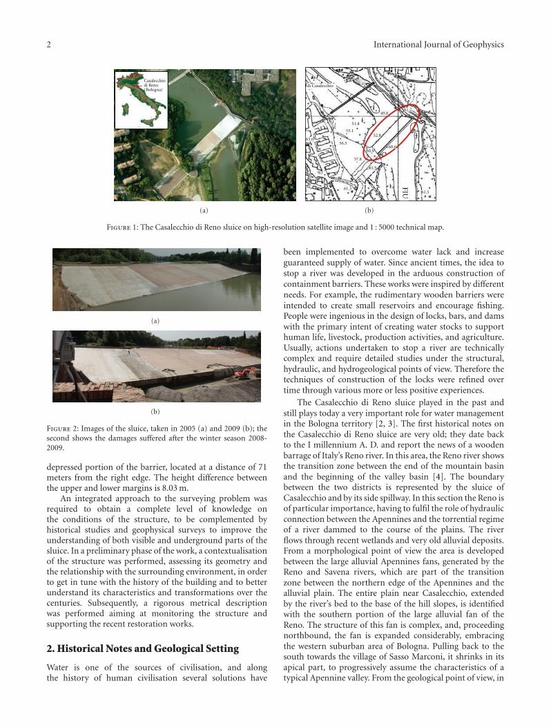
In this context, the first objective of this work is todiscuss—on an interesting case study—some of the possibil-ities provided today by engineering geomatics through theintegration of different surveying techniques and methods.The case study is related to the description of high-precisionsurveys and metrical investigations on the main elements ofthe ancient sluice located in Casalecchio di Reno on the Renoriver, close to Bologna, Italy (Figure 1 and Figure 2). Thesluice is considered the most ancient hydraulic system still inactivity in Europe and was recently included in the UNESCOlist of Monuments and Sites as Messengers of Peace.
As for the geometry of the structure, it must be noted thatthe upper edge is not horizontal, but it shows a depressedarea in order to redirect water to the hydraulic right edge ofthe dam, where a water deviation is performed. The lengthof the sluice is 160.4 meters. The highest point is located atthe left edge and it rises to 0.54 m with respect to the most
2 International Journal of Geophysics
Casalecchiodi Reno(Bologna)
(a)
Ch63.6
57.8
63
61.3
61.5
56.5
53.1
61 51.8
52.8
60.6
61.5
60.9
49.861.2
61.3
di Casalecchio
FIU
(b)
Figure 1: The Casalecchio di Reno sluice on high-resolution satellite image and 1 : 5000 technical map.
(a)
(b)
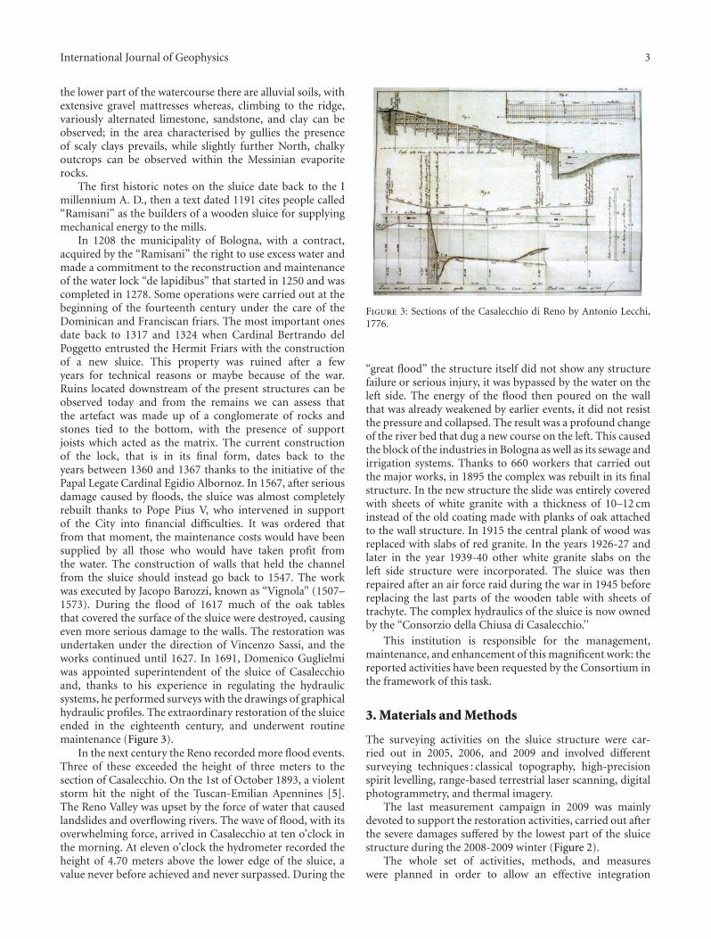
Figure 2: Images of the sluice, taken in 2005 (a) and 2009 (b); thesecond shows the damages suffered after the winter season 2008-2009.
depressed portion of the barrier, located at a distance of 71meters from the right edge. The height difference betweenthe upper and lower margins is 8.03 m.
An integrated approach to the surveying problem wasrequired to obtain a complete level of knowledge onthe conditions of the structure, to be complemented byhistorical studies and geophysical surveys to improve theunderstanding of both visible and underground parts of thesluice. In a preliminary phase of the work, a contextualisationof the structure was performed, assessing its geometry andthe relationship with the surrounding environment, in orderto get in tune with the history of the building and to betterunderstand its characteristics and transformations over thecenturies. Subsequently, a rigorous metrical descriptionwas performed aiming at monitoring the structure andsupporting the recent restoration works.
2. Historical Notes and Geological Setting
Water is one of the sources of civilisation, and alongthe history of human civilisation several solutions have
been implemented to overcome water lack and increaseguaranteed supply of water. Since ancient times, the idea tostop a river was developed in the arduous construction ofcontainment barriers. These works were inspired by differentneeds. For example, the rudimentary wooden barriers wereintended to create small reservoirs and encourage fishing.People were ingenious in the design of locks, bars, and damswith the primary intent of creating water stocks to supporthuman life, livestock, production activities, and agriculture.Usually, actions undertaken to stop a river are technicallycomplex and require detailed studies under the structural,hydraulic, and hydrogeological points of view. Therefore thetechniques of construction of the locks were refined overtime through various more or less positive experiences.
The Casalecchio di Reno sluice played in the past andstill plays today a very important role for water managementin the Bologna territory [2, 3]. The first historical notes onthe Casalecchio di Reno sluice are very old; they date backto the I millennium A. D. and report the news of a woodenbarrage of Italy’s Reno river. In this area, the Reno river showsthe transition zone between the end of the mountain basinand the beginning of the valley basin [4]. The boundarybetween the two districts is represented by the sluice ofCasalecchio and by its side spillway. In this section the Reno isof particular importance, having to fulfil the role of hydraulicconnection between the Apennines and the torrential regimeof a river dammed to the course of the plains. The riverflows through recent wetlands and very old alluvial deposits.From a morphological point of view the area is developedbetween the large alluvial Apennines fans, generated by theReno and Savena rivers, which are part of the transitionzone between the northern edge of the Apennines and thealluvial plain. The entire plain near Casalecchio, extendedby the river’s bed to the base of the hill slopes, is identifiedwith the southern portion of the large alluvial fan of theReno. The structure of this fan is complex, and, proceedingnorthbound, the fan is expanded considerably, embracingthe western suburban area of Bologna. Pulling back to thesouth towards the village of Sasso Marconi, it shrinks in itsapical part, to progressively assume the characteristics of atypical Apennine valley. From the geological point of view, in
International Journal of Geophysics 3
the lower part of the watercourse there are alluvial soils, withextensive gravel mattresses whereas, climbing to the ridge,variously alternated limestone, sandstone, and clay can beobserved; in the area characterised by gullies the presenceof scaly clays prevails, while slightly further North, chalkyoutcrops can be observed within the Messinian evaporiterocks.
The first historic notes on the sluice date back to the Imillennium A. D., then a text dated 1191 cites people called“Ramisani” as the builders of a wooden sluice for supplyingmechanical energy to the mills.
In 1208 the municipality of Bologna, with a contract,acquired by the “Ramisani” the right to use excess water andmade a commitment to the reconstruction and maintenanceof the water lock “de lapidibus” that started in 1250 and wascompleted in 1278. Some operations were carried out at thebeginning of the fourteenth century under the care of theDominican and Franciscan friars. The most important onesdate back to 1317 and 1324 when Cardinal Bertrando delPoggetto entrusted the Hermit Friars with the constructionof a new sluice. This property was ruined after a fewyears for technical reasons or maybe because of the war.Ruins located downstream of the present structures can beobserved today and from the remains we can assess thatthe artefact was made up of a conglomerate of rocks andstones tied to the bottom, with the presence of supportjoists which acted as the matrix. The current constructionof the lock, that is in its final form, dates back to theyears between 1360 and 1367 thanks to the initiative of thePapal Legate Cardinal Egidio Albornoz. In 1567, after seriousdamage caused by floods, the sluice was almost completelyrebuilt thanks to Pope Pius V, who intervened in supportof the City into financial difficulties. It was ordered thatfrom that moment, the maintenance costs would have beensupplied by all those who would have taken profit fromthe water. The construction of walls that held the channelfrom the sluice should instead go back to 1547. The workwas executed by Jacopo Barozzi, known as “Vignola” (1507–1573). During the flood of 1617 much of the oak tablesthat covered the surface of the sluice were destroyed, causingeven more serious damage to the walls. The restoration wasundertaken under the direction of Vincenzo Sassi, and theworks continued until 1627. In 1691, Domenico Guglielmiwas appointed superintendent of the sluice of Casalecchioand, thanks to his experience in regulating the hydraulicsystems, he performed surveys with the drawings of graphicalhydraulic profiles. The extraordinary restoration of the sluiceended in the eighteenth century, and underwent routinemaintenance (Figure 3).
In the next century the Reno recorded more flood events.Three of these exceeded the height of three meters to thesection of Casalecchio. On the 1st of October 1893, a violentstorm hit the night of the Tuscan-Emilian Apennines [5].The Reno Valley was upset by the force of water that causedlandslides and overflowing rivers. The wave of flood, with itsoverwhelming force, arrived in Casalecchio at ten o’clock inthe morning. At eleven o’clock the hydrometer recorded theheight of 4.70 meters above the lower edge of the sluice, avalue never before achieved and never surpassed. During the
Figure 3: Sections of the Casalecchio di Reno by Antonio Lecchi,1776.
“great flood” the structure itself did not show any structurefailure or serious injury, it was bypassed by the water on theleft side. The energy of the flood then poured on the wallthat was already weakened by earlier events, it did not resistthe pressure and collapsed. The result was a profound changeof the river bed that dug a new course on the left. This causedthe block of the industries in Bologna as well as its sewage andirrigation systems. Thanks to 660 workers that carried outthe major works, in 1895 the complex was rebuilt in its finalstructure. In the new structure the slide was entirely coveredwith sheets of white granite with a thickness of 10–12 cminstead of the old coating made with planks of oak attachedto the wall structure. In 1915 the central plank of wood wasreplaced with slabs of red granite. In the years 1926-27 andlater in the year 1939-40 other white granite slabs on theleft side structure were incorporated. The sluice was thenrepaired after an air force raid during the war in 1945 beforereplacing the last parts of the wooden table with sheets oftrachyte. The complex hydraulics of the sluice is now ownedby the “Consorzio della Chiusa di Casalecchio.’’
This institution is responsible for the management,maintenance, and enhancement of this magnificent work: thereported activities have been requested by the Consortium inthe framework of this task.
3. Materials and Methods
The surveying activities on the sluice structure were car-ried out in 2005, 2006, and 2009 and involved differentsurveying techniques : classical topography, high-precisionspirit levelling, range-based terrestrial laser scanning, digitalphotogrammetry, and thermal imagery.
The last measurement campaign in 2009 was mainlydevoted to support the restoration activities, carried out afterthe severe damages suffered by the lowest part of the sluicestructure during the 2008-2009 winter (Figure 2).
The whole set of activities, methods, and measureswere planned in order to allow an effective integration
4 International Journal of Geophysics
between the various techniques chosen on the basis of theirrespective potential. Regarding the horizontal and verticalreference systems, the main work was carried out on alocal system, but the availability in the same area of a GPSpoint already established by the University of Bologna forregional subsidence monitoring, and of a benchmark froman important district levelling network, permits to move allthe results in absolute system when necessary.
4. High-Precision Three-DimensionalTopographic Surveys
In 2005, a three-dimensional network has been installed onthe sluice to achieve high-precision three-dimensional mea-surements using highly accurate engineering total stations(Figure 4). The network was surveyed in 2005, 2006, and2009; in the last campaign, five points in the lower border ofthe slide were lost due to the damages occurred in the 2008-2009 winter.
The control network consisted of 11 self-centeringdevices on the slide, anchored to the structure below theslabs, and used for the positioning of the retroreflectiveprisms and also of the reference targets used in the laserscans. Moreover, 22 additional points were identified, alreadypresent in the structure, that were used also as referencebenchmarks for the high-precision geometric levelling.
From two positions located outside the structure ofthe dam, the measurements were carried out using high-precision Leica total stations (TCA2003 and TC2003 in2005–2006, two TCA2003 in 2009), characterised by anangular accuracy of 0.5′′ and a nominal precision of1 mm + 1 ppm for the distances. The total stations wereequipped with dual-axis compensators, which compensatethe horizontal and vertical readings for small deviations ofthe principal axes with respect to the vertical line; the roboticstation Leica TCA2003 is able to automatically recognize thecentre of the targets.
The atmospheric refraction was modelled from the mea-surements of air temperatures, barometric pressure levels,and relative humidity recorded during the measurementson both sides of the structure. In fact, knowledge ofthe refractive index (n) of the prevailing atmosphere isnecessary in order to apply a correction for velocity to themeasured distance; the classical approach described by [6],subsequently adapted considering wavelengths between 560and 900 nm, was adopted.
A rigorous least squares adjustment of the dataset wascarried out adopting a redundant number of measurements,but using minimum constraints to define the referencesystem; in this way the coordinates of all control pointswere computed. Regarding the precision of the surveys, forthe 11 points along the chute the major semiaxis of theassociated error ellipses at 95% probability level reachedmaximum values on the order of 2.5 mm whilst worse resultswere obtained for the other points not characterised byself-centring devices. The comparison between subsequentcampaigns (2005 versus 2006, 2009 versus 2006), takinginto account the confidence intervals associated to the
coordinates, has generally shown nonsignificant planimetricmovements for the structure.
5. Differential Levelling
Aiming at detecting high-precision estimates of elevationchanges, annual spirit levelling surveys have been performedby means of high-accuracy digital levels.
Due to the impossibility, for logistics problems, to realizespecific benchmarks along the superior and inferior bordersof the sluice, a network of 25 benchmarks, mainly defined bysmall holes along the borders (on steel joints or on stones),was established in 2005. The height origin was benchmark 21located on the top boundary of the sluice (Figure 4(b)).
The levelling measurements have been carried out with aclassical scheme using two invar staffs and by interconnectedclosed rings to achieve redundant data. The benchmarkheights coming from the statistical analysis of the obser-vations (adjustment computation), have been characterisedby a precision to a tenth of a millimetre. The difference inelevation between surveys were in the order of the standarddeviation associated to the adjusted heights, proving that themain structure did not suffer significant movements, withthe exception of the points located in the inferior border nearthe damaged zone, where uplift movements in the order of1 mm were detected (Figure 5(b)).
6. Terrestrial Laser Scanning Surveys, DigitalPhotogrammetry, and Thermal Surveys
High-density three-dimensional point clouds have beensurveyed by means of terrestrial laser scanner (TLS) andintegration with digital photogrammetry [7].
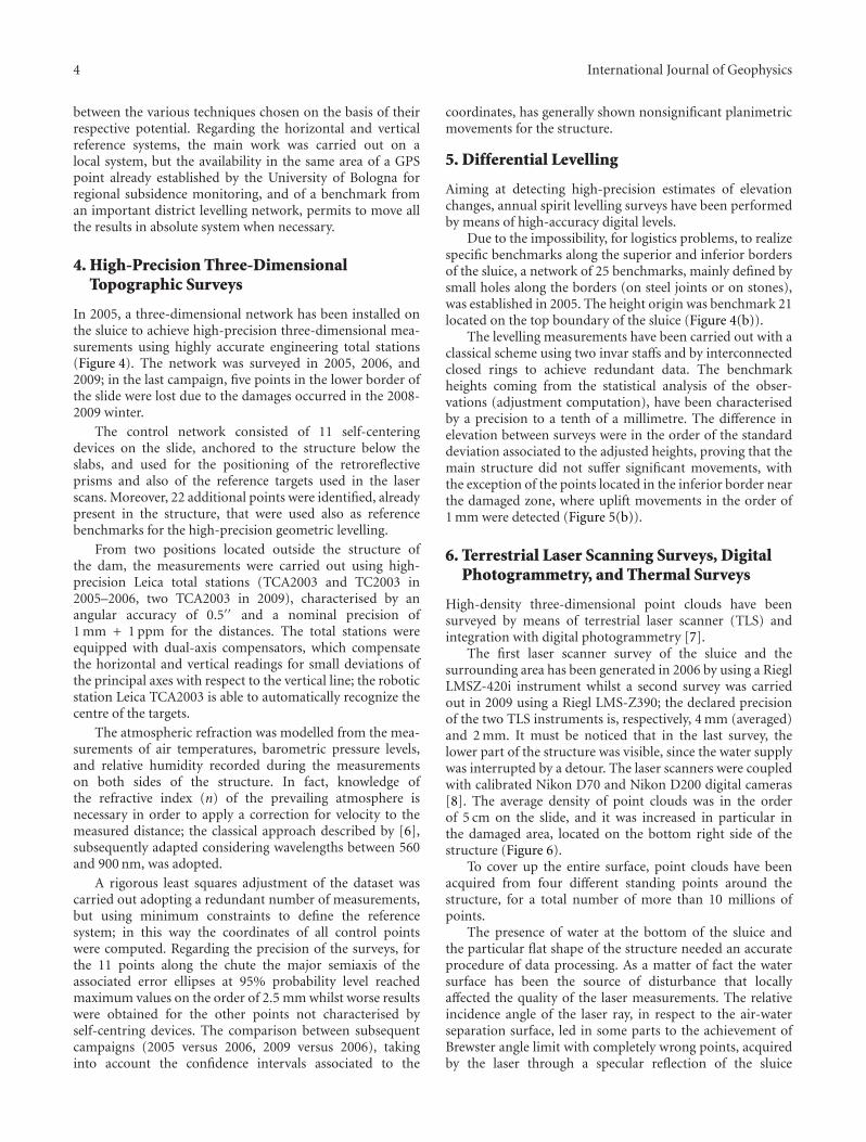
The first laser scanner survey of the sluice and thesurrounding area has been generated in 2006 by using a RieglLMSZ-420i instrument whilst a second survey was carriedout in 2009 using a Riegl LMS-Z390; the declared precisionof the two TLS instruments is, respectively, 4 mm (averaged)and 2 mm. It must be noticed that in the last survey, thelower part of the structure was visible, since the water supplywas interrupted by a detour. The laser scanners were coupledwith calibrated Nikon D70 and Nikon D200 digital cameras[8]. The average density of point clouds was in the orderof 5 cm on the slide, and it was increased in particular inthe damaged area, located on the bottom right side of thestructure (Figure 6).
To cover up the entire surface, point clouds have beenacquired from four different standing points around thestructure, for a total number of more than 10 millions ofpoints.
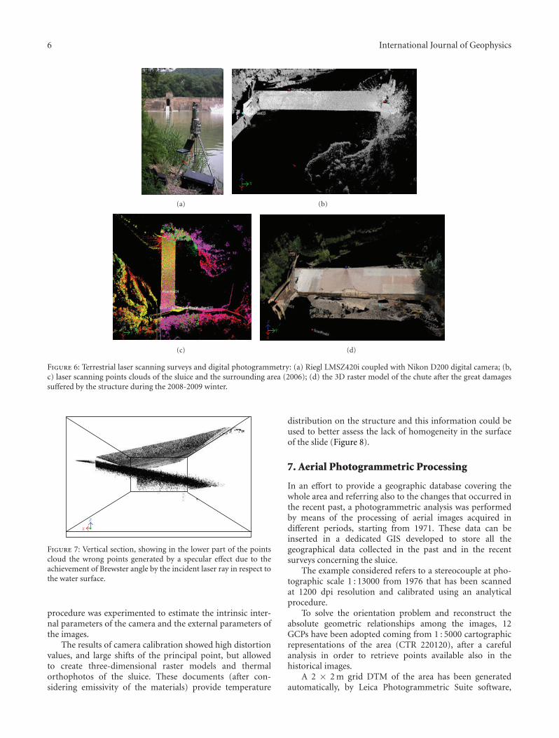
The presence of water at the bottom of the sluice andthe particular flat shape of the structure needed an accurateprocedure of data processing. As a matter of fact the watersurface has been the source of disturbance that locallyaffected the quality of the laser measurements. The relativeincidence angle of the laser ray, in respect to the air-waterseparation surface, led in some parts to the achievement ofBrewster angle limit with completely wrong points, acquiredby the laser through a specular reflection of the sluice

International Journal of Geophysics 5
(a)
3
7
4
11
6
2
9
5
8
1
21
10
595857565554535251
3120p 32 33 34 35 36 37 38 39 23p40 41 42
60CH
50 m
(b) (c) (d)
Figure 4: Classical topographic surveying : (a) total station; (b) scheme of control points distribution; (c) examples of GCPs characterisedby forced centering devices (outside the structure and on the slide, resp.) measured using prisms; (d) map of the 3D adjusted network.
(a)
00
10 20 30 40 50 60
0.10.20.30.4
0.50.60.70.80.9
1
5153
54
55
(m)
(mm
)
(b)
Figure 5: Field operations of high-precision spirit leveling (a); vertical displacements concerning the 2006–2009 time span for fourbenchmarks located on the bottom of the slide near the damaged zone (b).
structures (Figure 7); in this case the mirror was accidentallyrealised by the water surface itself. These points have beeneliminated by appropriate filtering.
The flat and gently sloping surface of the chute, togetherwith really small incidence angles, from the stations on thebottom, produced a surface affected by an unreal roughnessand unexpected outliers which have been reduced by meansof smoothing and filtering procedure. In this situation itmust be considered that the laser footprint is very elongated,affecting the precision of the measured point.
After the postprocessing phases of laser data (filtering,merging, decimation, etc.) the point clouds have been trian-gulated, forming a continuous digital surface model (DSM)by means of interpolation algorithms.
The images collected with the calibrated digital camerasupplied—through a postprocess—a textured representationof the three-dimensional surface models and the trueorthophoto mosaics.
The resulting products of the laser surveys have beenclouds of three-dimensional points referred to the same localreference system. The registration of the multiple scans hasbeen performed using dedicated cylindrical retroreflectorsplaced inside the chute plan, using the same self-centringdevices adopted for the planimetric survey. By so doing alsothe laser scanner data were referred to the same system of theother data.
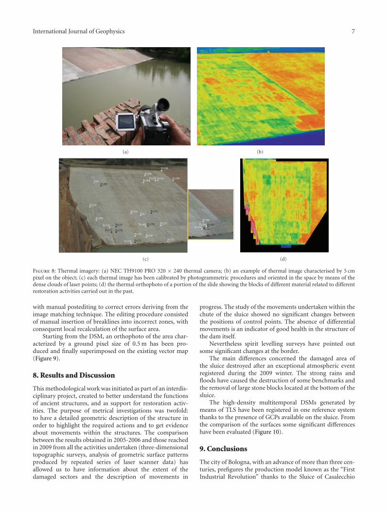
During 2009, the sluice has been furthermore surveyedby means of a thermal camera, in order to investigate thecapability of metrical use of thermal images.
The test has been performed by means of an NECThermo Tracer 9100 Pro, characterised by a single spectralband in the 8–14 µm interval, a sensitivity of 0.08 K anda field of view ranging from 16◦ to 21◦. The camera ischaracterised by an uncooled focal plane array detector, 320× 240 pixels.
The thermographic camera detects radiation in thethermal infrared range of the electromagnetic spectrum andproduces images of that radiation which could be used inthe same way as conventional photogrammetric images. Themain problem for integrating these data with the other is thegeometric calibration of the camera, and the stability of thegeometry along the images sequences. Once these problemsare solved, these low-resolution thermal images can be usedalso for a variety of metrical-based applications [9].
Three coverage strips of the sluice have been collectedtrying to cover the entire structure from different points ofview.
In order to dispose of a large set of visible groundcontrol points either for exterior and interior orientation, adense three-dimensional model of the sluice coming fromthe terrestrial laser scanning survey was used, recognisingon the model the control points needed; a field calibration
6 International Journal of Geophysics
(a)
x
Z
Y
(b)
Z
Y
X
(c)
Z
Y
X
(d)
Figure 6: Terrestrial laser scanning surveys and digital photogrammetry: (a) Riegl LMSZ420i coupled with Nikon D200 digital camera; (b,c) laser scanning points clouds of the sluice and the surrounding area (2006); (d) the 3D raster model of the chute after the great damagessuffered by the structure during the 2008-2009 winter.
Z
X
Figure 7: Vertical section, showing in the lower part of the pointscloud the wrong points generated by a specular effect due to theachievement of Brewster angle by the incident laser ray in respect tothe water surface.
procedure was experimented to estimate the intrinsic inter-nal parameters of the camera and the external parameters ofthe images.
The results of camera calibration showed high distortionvalues, and large shifts of the principal point, but allowedto create three-dimensional raster models and thermalorthophotos of the sluice. These documents (after con-sidering emissivity of the materials) provide temperature
distribution on the structure and this information could beused to better assess the lack of homogeneity in the surfaceof the slide (Figure 8).
7. Aerial Photogrammetric Processing
In an effort to provide a geographic database covering thewhole area and referring also to the changes that occurred inthe recent past, a photogrammetric analysis was performedby means of the processing of aerial images acquired indifferent periods, starting from 1971. These data can beinserted in a dedicated GIS developed to store all thegeographical data collected in the past and in the recentsurveys concerning the sluice.
The example considered refers to a stereocouple at pho-tographic scale 1 : 13000 from 1976 that has been scannedat 1200 dpi resolution and calibrated using an analyticalprocedure.
To solve the orientation problem and reconstruct theabsolute geometric relationships among the images, 12GCPs have been adopted coming from 1 : 5000 cartographicrepresentations of the area (CTR 220120), after a carefulanalysis in order to retrieve points available also in thehistorical images.
A 2 × 2 m grid DTM of the area has been generatedautomatically, by Leica Photogrammetric Suite software,
International Journal of Geophysics 7
(a) (b)
Pc205
Pc276Tp11
Tp4
Pc139
Pc206
Pc210
Pc181 Pc264Pc260
Pc152
Pc173
Pc174Pc138
Pc275Pc266
Pc273
Pc303
Pc298
Pc301 Pc299Pc302Pc304
Pc265
Pc261
Pc259Pc155
Pc172
Pc178Pc177
(c) (d)
Figure 8: Thermal imagery: (a) NEC TH9100 PRO 320 × 240 thermal camera; (b) an example of thermal image characterised by 5 cmpixel on the object; (c) each thermal image has been calibrated by photogrammetric procedures and oriented in the space by means of thedense clouds of laser points; (d) the thermal orthophoto of a portion of the slide showing the blocks of different material related to differentrestoration activities carried out in the past.
with manual postediting to correct errors deriving from theimage matching technique. The editing procedure consistedof manual insertion of breaklines into incorrect zones, withconsequent local recalculation of the surface area.
Starting from the DSM, an orthophoto of the area char-acterized by a ground pixel size of 0.5 m has been pro-duced and finally superimposed on the existing vector map(Figure 9).
8. Results and Discussion
This methodological work was initiated as part of an interdis-ciplinary project, created to better understand the functionsof ancient structures, and as support for restoration activ-ities. The purpose of metrical investigations was twofold:to have a detailed geometric description of the structure inorder to highlight the required actions and to get evidenceabout movements within the structures. The comparisonbetween the results obtained in 2005-2006 and those reachedin 2009 from all the activities undertaken (three-dimensionaltopographic surveys, analysis of geometric surface patternsproduced by repeated series of laser scanner data) hasallowed us to have information about the extent of thedamaged sectors and the description of movements in
progress. The study of the movements undertaken within thechute of the sluice showed no significant changes betweenthe positions of control points. The absence of differentialmovements is an indicator of good health in the structure ofthe dam itself.
Nevertheless spirit levelling surveys have pointed outsome significant changes at the border.
The main differences concerned the damaged area ofthe sluice destroyed after an exceptional atmospheric eventregistered during the 2009 winter. The strong rains andfloods have caused the destruction of some benchmarks andthe removal of large stone blocks located at the bottom of thesluice.
The high-density multitemporal DSMs generated bymeans of TLS have been registered in one reference systemthanks to the presence of GCPs available on the sluice. Fromthe comparison of the surfaces some significant differenceshave been evaluated (Figure 10).
9. Conclusions
The city of Bologna, with an advance of more than three cen-turies, prefigures the production model known as the “FirstIndustrial Revolution” thanks to the Sluice of Casalecchio

8 International Journal of Geophysics
(a) (b)
Figure 9: The orthophoto (a) and the superimposition of vector map on a detail related to the sluice area (b).
(a)
(b)
Figure 10: Detail of the damaged area at the bottom of the sluice(2009) before restoration: (a) RGB image; (b) TLS 3D raster model.
which can be considered as a symbol of this new economicmodel.
Due the importance of this hydraulic structure, thepublic owners always demonstrated care and periodicalrestoration works have been performed.
Starting from 2005 a multidisciplinary project concern-ing the full study of the sluice took place. As a result of thegeomatic surveys performed, a 3D model of the structurehas been generated. Concerning the monitoring of thestability of the sluice by means of topographic methods, nosignificant displacements have been detected (exceptions arerepresented by a few benchmarks located on the bottomof the structure, close to the damaged zone). These resultsconfirm the good health of the old structure.
Acknowledgments
The authors want to acknowledge the “Consorzio dellaChiusa di Casalecchio e del Canale di Reno,” in particularF. Marchi, for allowing the possibility to realize this work,
and A. Raffagli, responsible for the structural works. Thanksalso to C. Bonini, G. Capone, D. Garbellini, F. Girardi, E.Mandanici, M. Mannina, B. Roffare, and M. A. Tini, for thecollaboration in different phases of the surveys.
References
[1] N. Cossons, Ed., Perspectives on Industrial Archaeology, LondonScience Museum, 2000.
[2] F. Maranesi, F. Marchi, M. Poli, and G. Tabarroni, Le Acque aBologna, Editrice Compositori, Bologna, Italy, 2005.
[3] A. Zanotti, Il Sistema delle Acque a Bologna dal XIII al XIXSecolo, Editrice Compositori, Bologna, Italy, 2000.
[4] A. Papetti, Casalecchio di Reno, Aspetti Idrogeologici del Territo-rio, Telesio Editrice, Milano, Italy, 2003.
[5] U. Brunelli and F. Canonici, La Chiusa di Casalecchio e i LavoriEseguiti dalla Provincia di Bologna per la Chiusura della Rotta diReno in Sinistra Avvenuta il 1◦ Ottobre 1893 e per la Sistemazionedel Fiume a monte della Chiusa, Regia Tipografia, Bologna, Italy,1896.
[6] H. Barrell and J. E. Sears, “The Refraction and dispersion ofair for visible spectrum,” Philosophical Transactions of the RoyalSociety of London. Series A, vol. 238, pp. 1–64, 1939.
[7] K. Kraus, Photogrammetry—Geometry from Images and LaserScans, De Gruyter, Berlin, Germany, 2007.
[8] T. Luhmann, S. Robson, S. Kyle, and I. Harley, Close RangePhotogrammetry, Whittles, 2006.
[9] H. Kaplan, Practical Applications of Infrared Thermal Sensingand Image Equipment, SPIE, 2007.

Submit your manuscripts athttp://www.hindawi.com
Hindawi Publishing Corporationhttp://www.hindawi.com Volume 2014
ClimatologyJournal of
EcologyInternational Journal of
Hindawi Publishing Corporationhttp://www.hindawi.com Volume 2014
EarthquakesJournal of
Hindawi Publishing Corporationhttp://www.hindawi.com Volume 2014
Hindawi Publishing Corporationhttp://www.hindawi.com
Applied &EnvironmentalSoil Science
Volume 2014
Mining
Hindawi Publishing Corporationhttp://www.hindawi.com Volume 2014
Journal of
Hindawi Publishing Corporation http://www.hindawi.com Volume 2014
International Journal of
Geophysics
OceanographyInternational Journal of
Hindawi Publishing Corporationhttp://www.hindawi.com Volume 2014
Journal of Computational Environmental SciencesHindawi Publishing Corporationhttp://www.hindawi.com Volume 2014
Journal ofPetroleum Engineering
Hindawi Publishing Corporationhttp://www.hindawi.com Volume 2014
GeochemistryHindawi Publishing Corporationhttp://www.hindawi.com Volume 2014
Journal of
Atmospheric SciencesInternational Journal of
Hindawi Publishing Corporationhttp://www.hindawi.com Volume 2014
OceanographyHindawi Publishing Corporationhttp://www.hindawi.com Volume 2014
Advances in
Hindawi Publishing Corporationhttp://www.hindawi.com Volume 2014
MineralogyInternational Journal of
Hindawi Publishing Corporationhttp://www.hindawi.com Volume 2014
MeteorologyAdvances in
The Scientific World JournalHindawi Publishing Corporation http://www.hindawi.com Volume 2014
Paleontology JournalHindawi Publishing Corporationhttp://www.hindawi.com Volume 2014
ScientificaHindawi Publishing Corporationhttp://www.hindawi.com Volume 2014
Hindawi Publishing Corporationhttp://www.hindawi.com Volume 2014
Geological ResearchJournal of
Hindawi Publishing Corporationhttp://www.hindawi.com Volume 2014
Geology Advances in