integrating manufacturing simulation tools using ... · pdf fileintegrating manufacturing...
TRANSCRIPT

INTEGRATING MANUFACTURING SIMULATION TOOLS USING
DISTRIBUTED OBJECT TECHNOLOGY
Nicola Senin Dipartimento di Ingegneria Industriale
Universita ' degli Studi di Perugia Via G.Duranti 93, 06125 Perugia
nsenin@unipg. it
Roberto Groppetti, Alessandro Rossi
Dipartimento di lngegneria Industriale Universita' degli Studi di Parma
Viale delle Scienze, 1-43100 Parma groppetti@ied. eng. unipr. it
David R. Wallace Dept. of Mechanical Engineering
Massachusetts Institute ofTechnology 77 Massachusetts Avenue, 02139 Cambridge, MA
A modular approach for modeling, simulation and control of production systems, embracing multiple domains from the shop floor level to the single workstation is presented. Applications and knowledge are integrated over a computer network in a concurrent engineering environment involving both software and human interaction. Integration is achieved by using Distributed Object Technology. To demonstrate the approach, a tool for shop floor simulation based on stochastic timed Petri Nets, and a toa/ for simulation of machine tool motions during part program execution are integrated using a framework based on Distributed Object Technology, to build a multiple domain model of a manufacturing cell. The implemented prototype can be used for process parameter configuration, system simulation, and eventually real time system supervision and control in a concu"ent engineering environment.
1. INTRODUCTION
Manufacturing systems are typically complex systems characterized by many issues, and can be modeled according to many different viewpoints and at many levels of detail. For each aspect of a manufacturing system, several methodologies and tools

452 Advances in Networked Enterprises
have been developed, each tailored towards specific modeling and analysis tasks. For example, CAM software is used to model CNC machining operations and to simulate the resulting machined surfaces. Multi-body software is used to analyze the kinematics and dynamics of machine tools and other entities on the shop floor. Discrete event or continuous time simulation software is used to model and analyze the behavior of the overall manufacturing system.
Sometimes, the need arises to represent aspects of a manufacturing system that embrace multiple domains and none of the specialized modeling methods is capable of fully represent the phenomenon in a satisfactory way. As an example, consider chatter in a machine tool. A general model for chatter should embrace multiple domains and detail levels - ranging from the effect of chatter on the machined surface to the dynamics of the machine tool. Furthermore, a really comprehensive representation should be able to model, at the shop floor level, the effects of chatter on the performance of the machine tool, and the reaction the rest of the system (e.g. in case a supervision system is programmed to take some recovery action).
Such a broad model, embracing multiple domains of the manufacturing system, does not lend itself to be represented by a single modeling methodology, or single commercial software tool.
One way to handle the problem is to build specific cross-disciplinary models that cover each specific problem, such as the one described above. The risk of this approach is uncontrolled proliferation of too many specialized software tools.
This work proposes to utilize existing tools and methodologies, each with its own strengths and weaknesses, and focus on their integration by means of information exchange, to realize cross-disciplinary models. According to this approach, each application is in charge of maintaining only one part of the overall model, and interaction with the other applications would maintain a concurrent analysis.
Furthermore, this approach establishes a foundation for collaborative work, or concurrent engineering: through information exchanges, local modifications to a portion of the model propagate as needed to the other parts of the model, showing local and remote effects of decisions and affecting all the participants in the modeling project.
In this work, Distributed Object Technology is used as the means to achieve information exchange between software applications over a computer network, and the Internet. The feasibility of the approach is demonstrated through the implementation of an example integrated simulation model of a manufacturing cell.
2. OUTLINE
First, a software tool for discrete event simulation of a manufacturing system at the shop floor level is introduced. The tool is based on a modular object-oriented formalism extending Petri Nets, that is the evolution of previous research on the topic.
Then, a software tool for modeling CNC machine tools during operation is introduced. The tool is being developed by the authors as an open framework to model different aspects of CNC machine tools, ranging from part program verification, to axis motion analysis and machining supervision and simulation.
Integrating manufacturing simulation tools using DOT 453
A multiple-domain model of a simple manufacturing cell is implemented by connecting the models built within the two tools into an integrated system by means of Distributed Object Technology. To this purpose, a software prototype called DOME (Distributed Object-based Modeling Environment) is used. The integrated system is used as an example to validate the approach. The prototype can be used by operators participating in collaborative activities, such as process parameter configuration, system simulation, and eventually, on line manufacturing system supervision.
3. MANUFACTURING SYSTEM MODELING WITH PETRI NETS
3.1 Fundamentals
Petri Nets (PN) are a formalism and a modeling tool that can be used, amongst many other things, for discrete-event simulation of manufacturing systems. Petri Nets come in different flavors (time-based, colored, stochastic, etc) to fulfill different simulation needs, but all share some common features. A PN model is a directed graph made of nodes called places and transitions. Directed arcs connect pairs of places with a transition in between. Tokens flow from the start place to the target place in the pair, their flow being controlled by the transitionflring rule, which is based on preconditions satisfied by the start place. In time-based and stochastic PN's the flow can be delayed deterministically, or by using probability distributions. The state of the system is modeled by the current state of the PN model, which in turn is defined by the place contents in terms of tokens (place marking). As the simulation runs, tokens flow from place to place, thus evolving the system towards other states. Further information on Petri Nets can be found in work by Brams (Brams 1983), while work in progress to define a standard formalism can be found in publications by ISO (ISO 1997).
In PN models of manufacturing systems, transitions are typically used to represent operations (e.g. machine a workpiece, transfer items, etc.) while places with their token contents represent states in the manufacturing process (e.g. workpiece ready, machine in use, etc.). Tokens can be used to enable/disable machine states, or to represent material or product flows through the manufacturing system. Transition delays model operation duration, or trigger the occurrence of time-based events (e.g. mean time between failure - MTBF). Once a PN model of a manufacturing system has been built, its behavior can be simulated. For previous work on using PN based approaches to model manufacturing systems see also work by Alla et al., and Boujault et al.(Alla et al. 1986; Bourjault et al. 1987). PN based tools for manufacturing systems were also developed by the authors in previous work (Groppetti et al. 1994).
3.2 Contribution to Petri Net Modeling of Manufacturing Systems
A modular, PN based tool is introduced that makes use of object-oriented programming concepts, encapsulating PN models into a set of predefined template

454 Advances in Networked Enterprises
entities (representing workstations, transfer lines, etc.) which can be combined as building blocks to model manufacturing systems.
When a template is instantiated to create a manufacturing entity, its attributes are set, and mapped to the corresponding features in the embedded PN. Figure I shows the template Petri Net for a generic machine tool performing a task. Some places have access control, working as interfaces to allow connections with other Petri Net modules. Generic machine tool template model
·----------------------------------------------, I I
_w _.()._.J___.() Wo ieee i Wece . - ______.. available : workpiece placed workpiece processed (read/write) Into product
I I ·- -------------------------------------------- -· Q.+------___,..-
available (read only)
Figure I - Template Petri Net for a generic machine tool processing a workpiece. The transition delays can be modeled as probability density functions. The gray places have access control privileges and interface the module with other modules.
If the set of available predefmed templates does not fulfill all the modeling needs, new templates can be defmed by extending the definition of existing ones, through a process which resembles object-oriented inheritance. Figure 2 shows the template model for a failure-prone machine tool, which extends the generic machine tool model by adding the needed places and transitions to model the mean time between failure (MTBF) and the mean time to repair (MTTR).
Failure-prone machine tool template model
: 1; _ ?'- _ ? ? Generic machine tool : 1 / • template model : _.
I I
rna me available
I I
Figure 2. - Template Petri Net for a failure-prone machine tool The PN model extends the template of the generic machine tool, that is contained within the gray box.

Integrating manufacturing simulation tools using DOT 455
PN modules can be combined to represent larger models. Figure 3 shows the PNbased software prototype built by the authors for manufacturing system modeling. A model of a manufacturing cell with two machine tools (workstations) is shown. The cell is obtained as the combination of two PN modules, the interfaces being connected through place fusion. The model of one of the two workstations is shown in Figure 3 as well.
pracct•_wuRph:cc
mtchlne2_avarllble
woftple.c:e__,rocclled
relute_wortplece
Figure 3 - Manufacturing cell with two workstations as it appears in the PN simulator software prototype. The top level PN and the PN of one of the two workstations are shown.
4. MANUFACTURING WORKSTATION MODELING
4.1 Fundamentals
In this work, the term "manufacturing workstation" is generally used to refer to machine tools, robots, conveyors, etc; even though we'll refer primarily to machine tools.
A single manufacturing workstation is a complex, multi-faceted system, as a matter of fact, no simpler than a whole manufacturing system. As already pointed out in the introduction, a wide range of tools and methods can be adopted to model different aspects of a manufacturing workstation, and the choice of which way to follow depends primarily on the modeling intent. None of the specialized strategies listed in the introduction (CAM, multi-body modeling, etc, finite element modeling, etc) is capable of a satisfactory representation of all the aspects involved even in the simplest machine tool. The need for unified modeling and simulation is felt, in

456 Advances in Networked Enterprises
particular for those modeling applications involving multiple-domains, and where phenomena originating at a certain level of detail, propagate their effects to many other layers of the system model. For example, recall the chatter modeling problem as briefly mentioned in the introduction.
4.2 Contribution to the Development of Simulation Tools at the Workstation Level
Several tools are being developed by the authors, each with the purpose of representing specific aspects of a machine tool. For example, part program execution simulation for multi-axis CNC machine tools, surface micro-geometry reconstruction for machining operations, modeling and simulation of supervision systems for CNC machine tools (e.g. for cutter wear and breakage).
These tools need to be designed in a modular form, so that they can be interconnected to form unified models embracing multiple domains.
In this paper, one of the tools under development is used, that simulates machine motion, when executing a part program. In this software tool, the machine body is built by importing CAD geometry (STL format) for the rigid parts, and using a specially developed language to describe the kinematics of the joints in terms of constraints and ranges of allowed motion. A section of the software is in charge of interpreting the part program and sending the proper motion commands to the simulated axes. With this approach a wide range of multi-axis machine architectures can be modeled and simulated while executing a part program. The software tool has been designed as a modular, open framework, that can be extended at will, to include more accurate models, e.g. for axis motion control, for machine working envelope calculations, for part program analysis (e.g. overall machining time).
5. DISTRIBUTED OBJECT TECHNOLOGY TO INTEGRATE MANUFACTURING MODELING SOFTWARE APPLICATIONS OVER THE INTERNET
5.1 Fundamentals
Distributed Object technology is about turning software applications into reusable modules, their functionality mapped to network-accessible services, and connecting them with each other according to a client-server paradigm to form integrated systems of applications distributed geographically over the intranets or the Internet. Distributed Object Technology enables collaboration and data sharing through information exchange between software applications, and consequently between users, thus establishing the effective foundations for a collaborative environment.
Previous work has demonstrated the capability of developing integrated models of complex design and manufacturing problems through the interconnection of different software applications distributed over a computer network, using Distributed Object technology as the means to achieve information exchange (Pahng et al. 1997; Senin et al. 1997; Pahng et al. 1998; Wallace et al. 2000). To validate the approach, a prototype software tool called DOME - (Distributed Object Modeling Environment) (Wallace, Abrahamson et al. 2000), was developed to ease

Integrating manufacturing simulation tools using DOT 457
the process of converting software application into network-enabled distributed objects (modules), and to allow the modeling of large distributed software models by graphically establishing service exchanges among modules.
The general schema of a network-enabled distributed object embedding a software application is shown in Figure 4.
Input parameters/ (std. protocol)
Services provided y (std. protocol)
Distributed object interface
protected data
Figure 4 - Distributed object architecture. The software application and its proprietary data are embedded (hidden and protected) within the object. The distributed object public interface maps inputs and outputs of the application into public services, which can be accessed by means of standard communication protocols.
Models built within DOME can be operated and their performance analyzed as the design parameters change. The effect of local modifications can be observed as it propagates to the remote parts of the model, thus effective concurrent engineering can be implemented, being each part of the model in control of one of the operators participating to the collaborative activity. DOME supports the CORBA specification for distributed object systems. CORBA is a widely accepted architectural framework for the network-based software integration at the enterprise level (Siegel 1996; OMG 1997; Technologies 1999).
5.2 Distributed Object Technology to Integrate Manufacturing Models Over the Internet
The integration of manufacturing software modeling tools over a computer network by means of Distributed Object Technology, allows the creation of integrated models of manufacturing systems. The manufacturing related information that must be shared among applications is exchanged through the network, so that each specialized part of the overall model, is always up to date, and consistent with the others.
An attempt to apply this approach to software integration in the manufacturing domain can be found also in work focusing on assembly process planning (Senin et al. 1999).
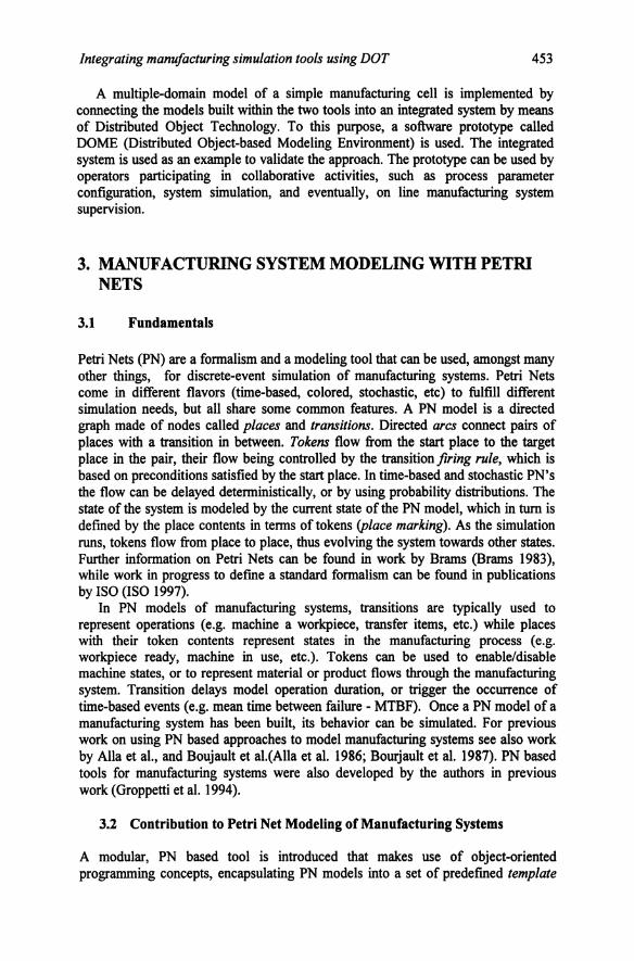
Figure 5 shows the architecture of the integrated software system to model an example manufacturing cell at the shop floor and workstation level. The integrated application is obtained by turning the previously seen PN software tool, and the workstation simulation tool into distributed objects and connecting them over the Internet.
The two applications, each providing a portion of the overall model, behave together like an integrated system since they exchange information, although geographically distributed. The shared information in this simple example is
458 Advances in Networked Enterprises
constituted by the workstation job execution times. This information is calculated by the workstation simulator, on the basis of the specified job, and then is sent to the PN simulator through the Internet, where it is mapped to the proper transition delays.
Embedded workstation simulator
Distributed object interface
Figure 5 - Architecture of the integrated software system for modeling a simple manufacturing cell at the shop floor, and workstation level. The two applications are embedded into distributed objects and communicate over a computer network.
Figure 6 shows the implemented prototype of the integrated software architecture. The two software applications were turned into distributed objects. A DOME model of the integrated system was created by acquiring the two distributed objects as DOME modules, and by graphically creating the service exchange connections between them.
A model such as the one illustrated above can be used as the base framework for collaborative engineering activities, such as for collaborative manufacturing process parameter configuration. Any model variation introduced by one of the participants would propagate to the whole model and local and remote effects would be highlighted as they happen. In the example model, a change in the part program would force the update of the workstation execution times, and thus, a variation in the delay modeled in the corresponding transitions, within the PN model. As a consequence of that, the PN simulation of the cell would return different results, highlighting the effects of the changes.
6. CONCLUSIONS
It was shown how, by means of Distributed Object Technology, it is possible to build models of manufacturing systems embracing multiple domains and detail levels. Multiple modeling techniques and tools, which are commonplace in manufacturing system and process modeling, can be integrated by means of information exchange to form larger more complete systems that overcome the limitations of each approach taken separately, facilitating the modeling of complex multi-faceted phenomena. Standard communication formalisms and protocols allow this interaction over a network of computers, so that even geographically distributed applications and operators can communicate and share common knowledge. Collaborating people can share knowledge and readily evaluate the effect that any decision will have on other participants.

Integrating manufacturing simulation tools using DOT 459
Many aspects need further investigation. For example, there is some concern on scalability of the proposed approach to large concurrent engineering scenarios. Model parameter distribution (the inverse concept of centralization) weakens the control on information consistency, and makes it more difficult to track the sources of modification. Also conflicts may arise from simultaneous decisions affecting the same variables, which need to be handled properly.
Some other issues derive from performance considerations, that can be strongly affected by bottlenecks generated by slower applications. That could become a relevant issue if this approach is to be extended from off-line modeling and analysis of manufacturing systems, to on-line control of manufacturing systems.
Figure 6 - Integrated DOME model of a manufacturing cell. The PN simulator and the workstation simulator are interconnected over the Internet and exchange information. The workstation simulator evaluates the part program execution times and the result is used to model the transition delay in the PN model.
7. REFERENCES
I. Alia, H. and Ladet, P. "Coloured Petri Nets: a tool for modelling, validation and simulation of FMS", In Flexible Manufacturing Systems: Methods and Studies, A. Kusiak ed., Amsterdam: Elsevier Science Publishers, 1986.

460 Advances in Networked Enterprises
2. Bourjault, A, Chappe, D. and Henrioud, J. M. "Elaboration automatique des gammes d'assemblage a l'aide de reseaux de Petri". In Proceedings of the RAI.R.O. APU-21-Grafcet et RdP, AFCET Gauthier-Villars, 1987.
3. Brarns, G. W. Reseaux de Petri: theorie et pratique. Paris: Masson, 1983. 4. Groppetti, R., Santucci, A. and Senin, N. "On the application of Coloured Petri Nets to Computer
Aided Assembly Planning". In Proceedings of the ETF A'94 IEEE Symposium on Emerging Technologies & Factory Automation, Tokyo, Japan: IEEE, 1994.
5. ISO, High-level Petri Nets - Concepts, Definitions and Graphical Notation. Committee Draft ISOIIEC 15909, 1997.
6. Pahng, K. F., Senin, N. and Wallace, D. R., "Modeling and Evaluation ofProduct Design Problems in a Distributed Design Environment". In Proceedings of the ASME DETC, Sacramento, California: ASME, 1997.
7. Pahng, K. F., Senin, N. and Wallace, D. R. Distributed modeling and evaluation of product design problems. Computer-Aided Design 1998; 30: 411-423 ..
8. Senin, N., Borland, N. and Wallace, D. R. "Distributed modeling of product design problems in a collaborative design environment". In Proceedings of the CIRP International Design Seminar: Multimedia Technologies for Collaborative Design and Manufacturing, Los Angeles, California: CIRP, 1997.
9. Siegel, J. CORBA, Fundamentals of programming. New York: John Wiley and Sons, 1996. 10. OMG, The Common Object Request Broker: Architecture and Specification Revision 2.0. 1997. 11. Iona Technologies, Orbix 3- User manual. 1999. 12. Wallace, D. R., Abrahamson, S., Senin, N. and Sferra, P. Integrated Design in a Service
Marketplace. Computer-aided Design 2000; 32: 97-107.