integrating user knowledge into design pattern detection · integrating user knowledge into design...
TRANSCRIPT

Integrating User Knowledge into
Design Pattern Detection
Thesis submitted for the degree of
Doctor of Philosophy
at the University of Leicester
by
Mohammad H. Alshira’HDepartment of Computer Science
University of Leicester
December 2015
Integrating User Knowledge into Design Pattern Detection
Mohammad H. Alshira’H
Abstract
Design pattern detection is useful for a range of software comprehension and main-tenance tasks. Tools that rely on static or dynamic analysis alone can produceinaccurate results, especially for patterns that rely on the run-time information.Some tools provide facilities for the developer to refine the results by adding theirown knowledge. Currently, however, the ability of tools to accommodate this knowl-edge is very limited; it can only pertain to the detected patterns and cannot provideadditional knowledge about the source code, or about its behaviour. In this the-sis, we propose an approach to combine existing pattern detection techniques witha structured feedback mechanism. This enables the developer to refine the detec-tion results by feeding-in additional knowledge about pattern implementations andsoftware behaviour. The motivation is that a limited amount of user input can com-plement the automated detection process, to produce results that are more accurate.To evaluate the approach we applied it to a selection of openly available softwaresystems. The evaluation was carried in two parts. First, an evaluation case studywas carried out to detect pattern instances in the selected systems with the helpof the user knowledge. Second, a user study of a broader range of expert users ofdesign patterns was conducted in order to investigate the impact of their knowledgeon the detection process, and to see whether it is realistic that the user can iden-tify useful knowledge for the detection process. The evaluation results indicate thatthe proposed approach can yield a significant improvement in the accuracy whilstrequiring a relatively small degree of user input from the developer. Moreover, theresults show that expert users can supplement the design pattern detection processwith a useful feedback that can enhance the detection of design pattern instances inthe source code.

AcknowledgementsIn the name of Allah, the Beneficent, the Merciful.
First and foremost, this work would not have been completed except by guidance ofAlmighty Allah that allowed my dreams to come true. I would like to thank Allahfor giving me the power to believe in myself and pursue my dreams.
I would like to take this opportunity to extend my deepest gratitude to my academicsupervisor, Dr Neil Walkinshaw, for constantly offering adequate supervision, andkeeping me on the right path during the work on this thesis. He dedicated numeroushours for giving me countless guidance, valuable suggestions, and continuous encour-agement. I greatly appreciate his immeasurable efforts for bringing my dreams intoreality.
I would like to thank my PhD co-supervisor, Professor Reiko Heckel, PhD tutor,Dr Fer-Jan de Vries, and Professor Thomas Erlebach for their guidance and sup-port during my PhD journey. I would also like to thank all the staff members ofthe Department of Computer Science at the University of Leicester, especially thedepartment manager, Mrs Karen Smith, for her kindness and encouragement. Iwould also like to thank the members of my thesis examining committee, ProfessorRick Thomas, Dr Ruzanna Chitchyan, and Dr Steve Counsell, for their valuablecomments and suggestions.
Many friends and colleagues have shared time with me, and they helped makingmy PhD enjoyable and make it memorable. I would like to thank Dr Moham-mad Kharabsheh, Dr Abdullah AlSokkar, Amin Ajlouni, and Haitham AlZabin.I would also like to especially thank Mohammed Alabdullatif, Alexey Bakhirkin,and Thomas Gransden. I would like to express my deep and sincere gratitude toall those who have participated in our user study, shared knowledge and offeredconstructive feedback. I would also like to take this opportunity to gratefully andsincerely thank my sponsor, Al al-Bayt University, for granting me full scholarshipto pursue my studies abroad.
Last but not least, I would like to thank my mother for being there for the happytimes and tough times, for accepting me as I am and for guiding through my life. Itwould have been harder without her warm prayers. I would also like to thank all myfamily members especially my brother, Malek, for his support and help. I dedicatethis thesis to my daughters, Mira and Sarah, who suffered the most as for not beingthere for them. I hope I could compensate the days I have spent away from themdoing this research. Finally, to the memory of my father who passed away when Iwas three years old. Father, I have not been with you enough to know everythingabout you but I love you and miss you dearly.
ii

Contents
Abstract i
Acknowledgements ii
List of Figures ix
List of Tables xi
Abbreviations xiii
1 INTRODUCTION 1
1.1 Research Context . . . . . . . . . . . . . . . . . . . . . . . . . . . . . 1
1.2 Reverse Engineering and Design Patterns . . . . . . . . . . . . . . . . 3
1.3 Research Problem . . . . . . . . . . . . . . . . . . . . . . . . . . . . . 4
1.4 Research Objectives . . . . . . . . . . . . . . . . . . . . . . . . . . . . 5
1.5 Thesis Outline . . . . . . . . . . . . . . . . . . . . . . . . . . . . . . . 7
2 DESIGN PATTERNS 9
2.1 History of Design Patterns . . . . . . . . . . . . . . . . . . . . . . . . 9
2.2 GoF Design Patterns . . . . . . . . . . . . . . . . . . . . . . . . . . . 11
2.2.1 Example - Adapter Pattern . . . . . . . . . . . . . . . . . . . 12
iii
Contents
2.3 The Relevance of Design Patterns . . . . . . . . . . . . . . . . . . . . 13
2.4 The Impact of Design Patterns . . . . . . . . . . . . . . . . . . . . . 14
2.5 Design Pattern Implementation . . . . . . . . . . . . . . . . . . . . . 15
2.6 Identification of Design Patterns . . . . . . . . . . . . . . . . . . . . . 16
3 BACKGROUND & LITERATURE REVIEW 18
3.1 Design Pattern Detection (DPD) . . . . . . . . . . . . . . . . . . . . 18
3.1.1 Classification of the literature in DPD . . . . . . . . . . . . . 21
3.1.1.1 Recovery . . . . . . . . . . . . . . . . . . . . . . . . 21
3.1.1.2 Formalisation . . . . . . . . . . . . . . . . . . . . . . 21
3.1.2 Measurement & Evaluation . . . . . . . . . . . . . . . . . . . 22
3.1.2.1 Precision & Recall . . . . . . . . . . . . . . . . . . . 23
3.1.2.2 Weighted F-Score . . . . . . . . . . . . . . . . . . . . 24
3.1.2.3 Role-Based Pattern Evaluation . . . . . . . . . . . . 24
3.1.2.4 P-MARt Pattern Repository . . . . . . . . . . . . . . 25
3.2 Design Pattern Detection Approaches . . . . . . . . . . . . . . . . . . 26
3.2.1 Static Analysis . . . . . . . . . . . . . . . . . . . . . . . . . . 30
3.2.2 Static/Dynamic Analysis . . . . . . . . . . . . . . . . . . . . . 31
3.2.3 Constraint Satisfaction Problem & Pattern Detection . . . . . 33
3.2.4 User Integration Approaches . . . . . . . . . . . . . . . . . . . 35
3.2.5 Micro-structures Approaches . . . . . . . . . . . . . . . . . . . 37
3.3 Design Pattern Detection Tools . . . . . . . . . . . . . . . . . . . . . 39
3.3.1 Comparative Studies . . . . . . . . . . . . . . . . . . . . . . . 39
3.3.2 Tools with User Capabilities . . . . . . . . . . . . . . . . . . . 40
3.4 Weaknesses of Existing Techniques . . . . . . . . . . . . . . . . . . . 42
3.5 Summary . . . . . . . . . . . . . . . . . . . . . . . . . . . . . . . . . 44
4 GUIDING DESIGN PATTERN DETECTION WITH HINTS 46
iv
Contents
4.1 Motivating Example . . . . . . . . . . . . . . . . . . . . . . . . . . . 47
4.2 Overview of the proposed approach . . . . . . . . . . . . . . . . . . . 50
4.3 Source Code Analysis . . . . . . . . . . . . . . . . . . . . . . . . . . . 52
4.4 Mapping to Constraint Satisfaction Problem . . . . . . . . . . . . . . 53
4.4.1 Variables . . . . . . . . . . . . . . . . . . . . . . . . . . . . . . 53
4.4.2 Constraints . . . . . . . . . . . . . . . . . . . . . . . . . . . . 54
4.4.3 Domain . . . . . . . . . . . . . . . . . . . . . . . . . . . . . . 56
4.4.4 Solution . . . . . . . . . . . . . . . . . . . . . . . . . . . . . . 57
4.5 Refinement Process . . . . . . . . . . . . . . . . . . . . . . . . . . . . 58
4.5.1 Providing Feedback in the Form of Hints . . . . . . . . . . . . 58
4.5.2 Example: The Iterative Feedback Process . . . . . . . . . . . 61
4.5.3 Using Templates to Guide Hint Selection . . . . . . . . . . . . 63
4.6 Hint Generation Process . . . . . . . . . . . . . . . . . . . . . . . . . 64
4.6.1 Methodology . . . . . . . . . . . . . . . . . . . . . . . . . . . 65
4.7 Implementation . . . . . . . . . . . . . . . . . . . . . . . . . . . . . . 67
4.8 Related Work . . . . . . . . . . . . . . . . . . . . . . . . . . . . . . . 71
4.9 Summary . . . . . . . . . . . . . . . . . . . . . . . . . . . . . . . . . 72
5 EXPERIMENTS 73
5.1 Case Study Research Question . . . . . . . . . . . . . . . . . . . . . . 73
5.2 Methodology . . . . . . . . . . . . . . . . . . . . . . . . . . . . . . . 74
5.2.1 Subject Systems . . . . . . . . . . . . . . . . . . . . . . . . . . 77
5.3 Results & Discussion . . . . . . . . . . . . . . . . . . . . . . . . . . . 78
5.4 Evaluation Against P-MARt Repository . . . . . . . . . . . . . . . . 81
5.5 Reasons for False Detection . . . . . . . . . . . . . . . . . . . . . . . 88
5.5.1 Design Pattern Variants . . . . . . . . . . . . . . . . . . . . . 88
5.5.2 Dynamic Data Flow . . . . . . . . . . . . . . . . . . . . . . . 88
v
Contents
5.5.3 Parser Capabilities . . . . . . . . . . . . . . . . . . . . . . . . 89
5.6 Threats to validity . . . . . . . . . . . . . . . . . . . . . . . . . . . . 90
5.6.1 Internal Validity . . . . . . . . . . . . . . . . . . . . . . . . . 90
5.6.2 External Validity . . . . . . . . . . . . . . . . . . . . . . . . . 91
5.6.3 Conclusion validity . . . . . . . . . . . . . . . . . . . . . . . . 91
5.7 Summary . . . . . . . . . . . . . . . . . . . . . . . . . . . . . . . . . 92
6 PATTERN DETECTION AND USER KNOWLEDGE 93
6.1 Aims and Objectives . . . . . . . . . . . . . . . . . . . . . . . . . . . 94
6.2 Research Question & Hypotheses . . . . . . . . . . . . . . . . . . . . 95
6.3 Methodology . . . . . . . . . . . . . . . . . . . . . . . . . . . . . . . 96
6.3.1 Survey Design . . . . . . . . . . . . . . . . . . . . . . . . . . . 97
6.3.1.1 Population and Sampling . . . . . . . . . . . . . . . 97
6.3.1.2 Questionnaire Form and Protocol . . . . . . . . . . . 98
6.3.1.3 Pilot Test . . . . . . . . . . . . . . . . . . . . . . . . 102
6.3.2 Survey Operation . . . . . . . . . . . . . . . . . . . . . . . . . 106
6.3.2.1 Preparation . . . . . . . . . . . . . . . . . . . . . . . 106
6.3.2.2 Collection . . . . . . . . . . . . . . . . . . . . . . . . 106
6.3.3 Data Analysis . . . . . . . . . . . . . . . . . . . . . . . . . . . 107
6.3.3.1 Data Coding . . . . . . . . . . . . . . . . . . . . . . 108
6.3.3.2 Descriptive Statistics . . . . . . . . . . . . . . . . . . 109
6.3.3.3 Hypothesis Testing . . . . . . . . . . . . . . . . . . . 110
6.3.3.4 Test of Normality . . . . . . . . . . . . . . . . . . . . 110
6.4 Results & Discussion . . . . . . . . . . . . . . . . . . . . . . . . . . . 112
6.4.1 The Frequency of Hints . . . . . . . . . . . . . . . . . . . . . . 113
6.4.2 The Relation between the Experience and Useful Hints . . . . 116
6.5 Threats to validity . . . . . . . . . . . . . . . . . . . . . . . . . . . . 118
vi
Contents
6.5.1 Internal Validity . . . . . . . . . . . . . . . . . . . . . . . . . 118
6.5.2 External Validity . . . . . . . . . . . . . . . . . . . . . . . . . 119
6.5.3 Conclusion validity . . . . . . . . . . . . . . . . . . . . . . . . 119
6.6 Summary . . . . . . . . . . . . . . . . . . . . . . . . . . . . . . . . . 120
7 CONCLUSIONS AND FUTURE WORK 121
7.1 Overall Summary . . . . . . . . . . . . . . . . . . . . . . . . . . . . . 121
7.2 Conclusions . . . . . . . . . . . . . . . . . . . . . . . . . . . . . . . . 123
7.2.1 Findings Significance in Design Pattern Detection . . . . . . . 124
7.2.2 Findings Significance in Software Maintenance . . . . . . . . . 125
7.3 Future Research Directions . . . . . . . . . . . . . . . . . . . . . . . . 126
A Implementation 129
A.1 InFamix (.mse) file . . . . . . . . . . . . . . . . . . . . . . . . . . . . 129
A.2 Basic-parser . . . . . . . . . . . . . . . . . . . . . . . . . . . . . . . . 131
A.3 CSP Input . . . . . . . . . . . . . . . . . . . . . . . . . . . . . . . . . 132
B Detection Constraints 133
B.1 Observer Design Pattern . . . . . . . . . . . . . . . . . . . . . . . . . 133
B.2 State/Strategy Design Pattern . . . . . . . . . . . . . . . . . . . . . . 135
B.3 Template Method Design Pattern . . . . . . . . . . . . . . . . . . . . 136
B.4 Command Design Pattern . . . . . . . . . . . . . . . . . . . . . . . . 137
C Hint Templates 138
C.1 Structural Hints . . . . . . . . . . . . . . . . . . . . . . . . . . . . . . 138
C.2 Sequential Hints . . . . . . . . . . . . . . . . . . . . . . . . . . . . . . 140
D Survey Request and Questionnaire Form 141
vii
Contents
D.1 Survey Request Letter . . . . . . . . . . . . . . . . . . . . . . . . . . 141
D.2 Questionnaire Form . . . . . . . . . . . . . . . . . . . . . . . . . . . . 142
D.2.1 Introduction . . . . . . . . . . . . . . . . . . . . . . . . . . . . 142
D.2.2 Demographic . . . . . . . . . . . . . . . . . . . . . . . . . . . 143
D.2.3 Selected Scenario . . . . . . . . . . . . . . . . . . . . . . . . . 144
D.2.3.1 Scenario 1 . . . . . . . . . . . . . . . . . . . . . . . . 144
D.2.3.2 Scenario 2 . . . . . . . . . . . . . . . . . . . . . . . . 146
D.2.3.3 Scenario 3 . . . . . . . . . . . . . . . . . . . . . . . . 148
Bibliography 150
viii
List of Figures
1.1 Thesis Structure . . . . . . . . . . . . . . . . . . . . . . . . . . . . . . 8
2.1 Adapter pattern structure [54] . . . . . . . . . . . . . . . . . . . . . 12
3.1 Key design pattern detection steps . . . . . . . . . . . . . . . . . . . 20
4.1 Example system, along with the corresponding method call graph . . 49
4.2 Command / Adapter patterns structures . . . . . . . . . . . . . . . . 49
4.3 An iterative pattern-detection approach . . . . . . . . . . . . . . . . . 50
4.4 CSP Example - Variables . . . . . . . . . . . . . . . . . . . . . . . . . 54
4.5 Simple encoding notations types . . . . . . . . . . . . . . . . . . . . . 55
4.6 CSP Example - Constraints . . . . . . . . . . . . . . . . . . . . . . . 55
4.7 CSP Example - Domain . . . . . . . . . . . . . . . . . . . . . . . . . 56
4.8 CSP Example - Solution . . . . . . . . . . . . . . . . . . . . . . . . . 57
4.9 Hints level of detail . . . . . . . . . . . . . . . . . . . . . . . . . . . . 59
4.10 Adapter pattern constraints . . . . . . . . . . . . . . . . . . . . . . . 61
4.11 Candidate Patterns . . . . . . . . . . . . . . . . . . . . . . . . . . . . 61
4.12 Command pattern candidate . . . . . . . . . . . . . . . . . . . . . . . 63
4.13 Example - Hint . . . . . . . . . . . . . . . . . . . . . . . . . . . . . . 64
4.14 Famix Core elements [42] . . . . . . . . . . . . . . . . . . . . . . . . . 67
4.15 Source code parser . . . . . . . . . . . . . . . . . . . . . . . . . . . . 68
ix

List of Figures
6.1 Questionnaire Form . . . . . . . . . . . . . . . . . . . . . . . . . . . . 101
6.2 Profile of respondents: Job Role . . . . . . . . . . . . . . . . . . . . . 112
6.3 Profile of respondents: Level of experience . . . . . . . . . . . . . . . 113
6.4 Positive Hints Frequencies . . . . . . . . . . . . . . . . . . . . . . . . 115
6.5 Negative Hints Frequencies . . . . . . . . . . . . . . . . . . . . . . . . 115
A.1 Example of .MSE file produced by InFamix . . . . . . . . . . . . . . . 130
A.2 Example of Basic Parser output . . . . . . . . . . . . . . . . . . . . . 131
A.3 Example of CSP input . . . . . . . . . . . . . . . . . . . . . . . . . . 132
B.1 Observer Design Pattern . . . . . . . . . . . . . . . . . . . . . . . . . 133
B.2 Observer Pattern - Detection Constraints . . . . . . . . . . . . . . . . . 134
B.3 State/Strategy Design Pattern . . . . . . . . . . . . . . . . . . . . . . 135
B.4 State/Strategy Pattern - Detection Constraints . . . . . . . . . . . . . . 135
B.5 Template Method Design Pattern . . . . . . . . . . . . . . . . . . . . . 136
B.6 Template Method - Detection Constraints . . . . . . . . . . . . . . . 136
B.7 Command Design Pattern . . . . . . . . . . . . . . . . . . . . . . . . . 137
B.8 Command Pattern - Detection Constraints . . . . . . . . . . . . . . . . . 137
D.1 Questionnaire - Scenario 1 . . . . . . . . . . . . . . . . . . . . . . . . . 145
D.2 Questionnaire - Scenario 2 . . . . . . . . . . . . . . . . . . . . . . . . . 147
D.3 Questionnaire - Scenario 3 . . . . . . . . . . . . . . . . . . . . . . . . . 148
x
List of Tables
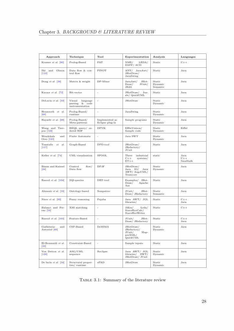
3.1 Summary of the literature review . . . . . . . . . . . . . . . . . . . . 28
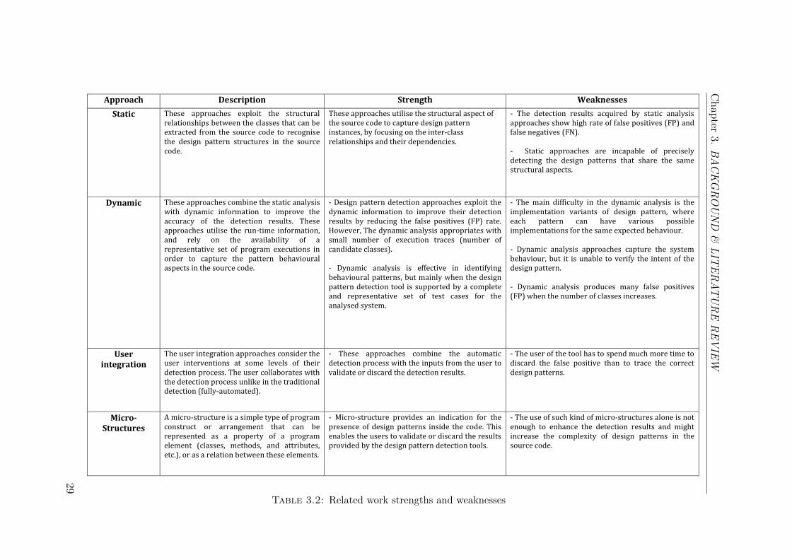
3.2 Related work strengths and weaknesses . . . . . . . . . . . . . . . . . 29
5.1 Subject systems . . . . . . . . . . . . . . . . . . . . . . . . . . . . . . 77
5.2 No hints/ structural hints phase detection results . . . . . . . . . . . 79
5.3 Sequential hints/ Ad-hoc hints phase detection results . . . . . . . . . 79
5.4 Results comparison based on P-MARt . . . . . . . . . . . . . . . . . 82
5.5 Results accuracy comparing to P-MARt . . . . . . . . . . . . . . . . 82
5.6 Detected/shared pattern instances with P-MARt in JHotDraw . . . . 86
5.7 Detected/shared pattern instances with P-MARt in JUnit . . . . . . 87
5.8 Detected/shared pattern instances with P-MARt in QuickUML . . . 87
6.1 Pilot Testing - Scenario 1 . . . . . . . . . . . . . . . . . . . . . . . . . 103
6.2 Pilot Testing - Scenario 2 . . . . . . . . . . . . . . . . . . . . . . . . . 104
6.3 Pilot Testing - Scenario 3 . . . . . . . . . . . . . . . . . . . . . . . . . 105
6.4 Measurement scale . . . . . . . . . . . . . . . . . . . . . . . . . . . . 108
6.5 The assessment of the usefulness of facts . . . . . . . . . . . . . . . . 109
6.6 Normality Testing - Scenario 1 . . . . . . . . . . . . . . . . . . . . . . 111
6.7 Normality Testing - Scenario 2 . . . . . . . . . . . . . . . . . . . . . . 111
6.8 Normality Testing - Scenario 3 . . . . . . . . . . . . . . . . . . . . . . 111
6.9 Selection of Hints (in percentage of number of respondents) . . . . . . 114
xi

List of Tables
6.10 The relation between the Experience and the Hints in Scenario 1 . . . 116
6.11 The relation between the Experience and the Hints in Scenario 2 . . . 116
6.12 The relation between the Experience and the Hints in Scenario 3 . . . 116
6.13 kruskall-Wallis Test . . . . . . . . . . . . . . . . . . . . . . . . . . . . 118
1 Structural Hints . . . . . . . . . . . . . . . . . . . . . . . . . . . . . . 139
2 Sequential Hints . . . . . . . . . . . . . . . . . . . . . . . . . . . . . . 140
xii

Abbreviations
ASG Abstract Semantic Graph
AST Abstract Syntax Tree
CFG Control Flow Graph
CSP Constraint Satisfaction Problem
DFA Deterministic Finite Automata
DPD Design Pattern Detection
DPML Design Pattern Mark-up Language
EDP Elemental Design Pattern
FOL First-order predicate Logic
FUJABA From Uml To Java And Back Again
GoF Gang of Four
GUI Graphical User Interface
ICAM Integrated Computer Aided Manufacturing
IDE Integrated Development Environment
IDEF0 ICAM DEfinition for Function Modeling
JavaXL Java eXtended Language
LOC Line Of Code
LTL Linear Temporal Logic
MOF Meta Object Facility
OCL Object Constraint Language
OOAD Object Oriented Analysis and Design
OWL Web Ontology Language
xiii
Abbreviations
P-MARt Pattern-like Micro Architecture Repository
PADL Pattern and Abstract-level Description Language
PDL Pattern Description Language
PROLOG PROgramming in LOGic
RDF Resource Description Framework
RSF Rigi Standard Format
SPQR System for Pattern Query and Recognition
SWRL Semantic Web Rule Language
UML Unified Modelling Language
VPML Visual Pattern Modeling Language
XML EXtensible Markup Language
xiv

This thesis is lovingly dedicated to my mother whodedicated her life for me
xv

Chapter 1
INTRODUCTION
This chapter introduces the research topic of this thesis. Section 1.1 discusses the
context within which the research problems arise. Section 1.2 introduces the relation
between reverse engineering and design patterns. Section 1.3 discusses the statement
of the problem. Section 1.4 presents the overall aim and objectives of this thesis.
It also summarises the research outcomes and contributions. Finally, Section 1.5
presents the thesis outline.
1.1 Research Context
Legacy software poses many important problems in software engineering. It needs to
evolve in order to meet the continuously changing requirements [84]. Such software
does not need to be substituted by new software but it needs to be maintained to
meet the new requirements and business needs. However, legacy software is rarely
accompanied by valid documentations and their source codes tend to be difficult to
comprehend. As reported by Sommerville [114], 50 % - 75 % of the efforts spent on
software development are dedicated to software maintenance.
1
Chapter 1. INTRODUCTION
Software maintenance tasks require a firm grasp of how the system was designed.
Obtaining such understanding is a particularly time-consuming activity [31]. An
object-oriented legacy code may contain thousands of classes and millions of lines of
codes. Furthermore, the design documents are often missing, or may not accurately
match the source code [90]. The main activity in the software maintenance process
is program comprehension [31]. It involves inspecting the source code artefacts in
order to gain a sufficient level of knowledge on the analysed system design and
architecture. This activity provides insights into the source code, which can help
the maintainer to understand the analysed system. Hence, the recovery of the source
code design and architecture makes the maintenance task easier.
Detecting design patterns improves the program comprehension process by under-
standing the source code at the design level [128]. Design patterns are descriptions
of solutions to frequently occurring software design problems [54]. The use of design
patterns is now widespread (both in academia and in the industry), and is routinely
taught in software design courses. Gang-of-Four (GoF) catalogue [54] is the most
widely used classification for design patterns. This catalogue presents 23 different de-
sign patterns categorised according to their purpose into Creational, Structural, and
Behavioural patterns. Each design pattern incorporates structural and behavioural
components, and has a particular abstract model specification. Furthermore, each
design has a unique intent that consists of a set of participants (classes) and de-
scribed with roles and responsibilities [66].
Design patterns are rarely explicitly documented in the source code [98]. This is
usually due to familiar factors such as the development time-pressure and the con-
tinuous code changes. The fact that a class plays a particular role in a pattern is often
implied by its name or by its relations to the other classes. Several pattern-mining
techniques have been developed to date to automatically highlight the presence of
design patterns in the source code. Most of such techniques operate by matching a
set of existing design pattern specifications to the source code elements (occasionally
with the help of run-time information collected from the program executions).
2
Chapter 1. INTRODUCTION
1.2 Reverse Engineering and Design Patterns
Reverse engineering is the idea of reconstructing the design of existing software
systems. Chikofsky and Cross [29] defined Reverse Engineering as:
“The process of analysing a subject system to identify the system’s components and
their relationships and to create representations of the system in another form or
at a higher level of abstraction”.
The aim of reverse engineering is to support software understanding, maintenance,
re-engineering, and evolution activities by improving program comprehension tasks
[127]. The use of design patterns in forward engineering is well-known. The idea
behind reverse engineering of design patterns is to detect the presence of pattern
instances in the source code of the analysed systems. This can provide better un-
derstanding of the software system.
Reverse engineering of the design patterns process utilises the source code of the
analysed system as the main source of information. It starts by parsing the source
code into an intermediate representation to extract the design facts (e.g. inter-class
relationships). Then, it performs pattern recognition based on the extracted infor-
mation. This is done by matching the extracted facts to the abstract specifications
of the design patterns. In particular, it detects occurrence of micro-architecture that
is similar to the pattern specifications [38].
The difficulty of reverse engineering patterns is not the same for all pattern cate-
gories. In structural patterns, most information can be recognised from the inter-
class relationships, which can be trivially extracted from the source code. Be-
havioural patterns, on the other hand, are considered the most difficult pattern
category to be detected [13]. This is because they rely on the availability of repre-
sentative sets of program executions, and because they cannot be detected from the
source code alone.
3
Chapter 1. INTRODUCTION
1.3 Research Problem
A number of approaches have been made during the last decade to reverse engineer
design patterns. A representative list of such approaches can be found in [60, 93,
117]. These approaches utilise the source code as the main source of information
for the analysed system. They developed meta-model catalogues, which contain
possible formalisations for design patterns. Such catalogues are used to obtain the
representation of design patterns and to allow for their automatic detection.
Current design pattern detection tools tend to rely mostly on a combination of a
static and a dynamic code analysis. Such tools are inaccurate, especially when
a design pattern has a substantial dynamic element. In fact, the set of pattern
candidates retrieved by most of the currently available automated processes are
not accurate. They, usually, fail to detect all the correct patterns and may also
detect patterns that are not correct. Thus, the fully automated detection process is
challenging. The principal reasons for this inaccuracy are as follows:
• Static analysis can be too conservative [46], which makes it difficult to differen-
tiate between design patterns with similar structures. Design pattern detection
tools often tend to rely on source code analysis where run-time behaviour can
be difficult to predict.
• Dynamic analysis depends mainly on inputs from the developers which may be
incomplete. Even if the tools incorporate run-time information, there remains
the (undecidable) problem of identifying a suitable set of inputs to trigger
the necessary information to elicit the behaviour that will expose the design
pattern [46].
• Design pattern implementations can slightly deviate from the formal design
pattern specifications used by the detection tools which make them harder to
detect.
4
Chapter 1. INTRODUCTION
Some approaches have attempted to address these problems by involving user inputs.
These approaches combine the automatic detection process with the inputs from
the user, i.e. validate or discard the detection results. They consider the user
interventions at some levels of their detection process. The user collaborates with
the detection process unlike in the traditional detection (fully-automated). However,
they permit a limited degree of user-interaction by allowing the user to annotate
certain classes and to delete inappropriate role assignments. It was noticed with the
approaches that support the user capabilities, the user has the ability to scrutinise
the detection results at some level of the detection process. The user can inspect
the final detection results by analysing the design pattern candidates and rolling out
the false positives. However, the user of the tool has to spend much more time to
discard the false positive than to trace the correct design patterns.
1.4 Research Objectives
The goal of this research is to develop a new structured design pattern detection
process supported by inputs from an expert user in order to enhance the accuracy
of the detection results. It considers the design pattern detection process as an
iterative and a user-driven process. The motivation is that limited amount of user
inputs can complement the automated analyses to produce detection results that
are much more accurate. This thesis proposes an approach that seeks to enable the
user to feed small hints into the detection process.
The work proposed in this thesis enables the developer to be much more expressive,
whilst remaining easy to use. For example, hints can provide information about the
dynamic behaviour of the program that might be impossible to verify from a finite
number of program executions. Hints can also provide a partial knowledge about
the implementations of a design pattern. The proposed approach is intended to be
compatible with existing (constraint-based) pattern detection approaches in order
5

Chapter 1. INTRODUCTION
to act as a complementary layer to enable additional feedback from the developer.
The following are the set of objectives:
1. Develop a new structured design pattern detection process to actively involve
the user in the detection process, and place user knowledge at the heart of the
design pattern detection process.
2. Enable expert users to supply their knowledge in an the form of gradually
acquired constraints.
3. Study the impact of user knowledge on the design pattern detection process.
This thesis argues that there is a real need for a hybrid detection approach combining
the automatic detection tools with the user inputs that support the design pattern
detection process when automatic means reach their limits. This research proposes a
framework enabling the user to supply domain knowledge in the form of constraints
and providing means to integrate this knowledge into the detection process. In order
to achieve the aforementioned goal, a new pattern detection framework was built,
which incorporates the user knowledge, and implements a prototype tool based on
involving the user inputs in the detection process. The evaluation was carried out
with respect to real software systems. The general outcomes and main contributions
achieved in this research are:
1. A user-driven design pattern reverse-engineering approach.
2. A set of ‘hint-templates’ to enable the easy supply of hints.
3. A proof-of-concept implementation.
4. An evaluation of the approach on three open-source systems.
5. A controlled user study of a broader range of expert users.
The key finding of this research is that it is necessary to actively involve the user
expert knowledge in the design pattern detection process. The user must be provided
with as much opportunity as possible to contribute their expert knowledge about
the system structure, its behaviour, and possible implementation deviations from
6
Chapter 1. INTRODUCTION
traditional pattern definitions. The evaluation results indicate that user intervention
has the potential to substantially increase the accuracy of the detected patterns.
Moreover, the results of the user study show that the expert user can supplement
the design pattern detection process with a useful feedback that can enhance the
detection of pattern instances in the source code.
1.5 Thesis Outline
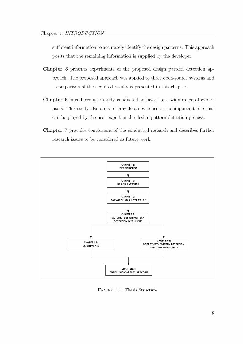
The structure of the thesis is shown in Figure 1.1. The thesis is organised into seven
chapters, the remaining chapters are described as follows:
Chapter 2 introduces the history of design patterns and explains how design pat-
terns have been interpreted in the context of object-oriented design. This
chapter also explains the general concept of design patterns, their classifica-
tions, and discusses the relevance of design patterns. Finally, this chapter
discusses the impact of using patterns, explains the implementation and the
identification of design patterns.
Chapter 3 presents background on the research topic and covers the main concepts
related to the design pattern detection process. This chapter also provides
a review of a wide range of detection approaches and tools that have been
proposed in the literature in order to assess the research contribution and
develop a clear direction for the proposed approach. Finally, this chapter
presents the main challenges in the design pattern detection area and highlights
the problems and limitations of current approaches.
Chapter 4 presents the proposed design pattern detection approach that places
the user knowledge at the heart of the design pattern detection process. The
approach is founded on the premise that the source code alone cannot provide
7
Chapter 1. INTRODUCTION
sufficient information to accurately identify the design patterns. This approach
posits that the remaining information is supplied by the developer.
Chapter 5 presents experiments of the proposed design pattern detection ap-
proach. The proposed approach was applied to three open-source systems and
a comparison of the acquired results is presented in this chapter.
Chapter 6 introduces user study conducted to investigate wide range of expert
users. This study also aims to provide an evidence of the important role that
can be played by the user expert in the design pattern detection process.
Chapter 7 provides conclusions of the conducted research and describes further
research issues to be considered as future work.
CHAPTER 1:INTRODUCTION
CHAPTER 3:BACKGROUND & LITERATURE
CHAPTER 4:GUIDING DESIGN PATTERN
DETECTION WITH HINTS
CHAPTER 6:USER STUDY: PATTERN DETECTION
AND USER KNOWLEDGE
CHAPTER 5:EXPERIMENTS
CHAPTER 7:CONCLUSIONS & FUTURE WORK
CHAPTER 2:DESIGN PATTERNS
Figure 1.1: Thesis Structure
8

Chapter 2
DESIGN PATTERNS
This chapter aims to introduce the history of design patterns, and explains how
design patterns have been interpreted in the context of object-oriented software
design. Section 2.1 explains the history of design patterns. Section 2.2 outlines
the general concept of patterns within object-oriented design. Section 2.3 discusses
the relevance of design patterns. Section 2.4 discusses the impact of using design
patterns. Section 2.5 explains their implementation. Finally, Section 2.6 discusses
the identification of design patterns.
2.1 History of Design Patterns
Patterns were invented as an architectural concept by Christopher Alexander in the
1960s and the 1970s [9]. Alexander defines a pattern as ‘’A recurring solution to
a common problem in a given context and system of forces”. Alexander published
several books on architectural design that were concerned with creating and using
patterns in the architecture domain. Alexander described a variety of patterns in
space, human existence, and events, with the aim of improving people’s living quality.
In the following decades, the books of Alexander inspired the domain of Computer
9
Chapter 2. DESIGN PATTERNS
Science. In 1987, Kent Beck and Ward Cunningham started experimenting with the
idea of applying patterns to software programming (specifically pattern languages).
In 1988, they [20] developed user interfaces in Smalltalk by using some ideas from
Alexander’s architecture patterns. Starting from the 1990s, the work on patterns
increased, as described below:
• In 1991, Jim Coplien developed a set of patterns called idioms in C++ [30].
These were a type of low level pattern specific to a programming language [27].
After that, Erich Gamma started to concentrate on recurring structures and
patterns in his PhD thesis [52].
• In 1992, numerous professionals in software design including Erich Gamma,
Richard Helm, Ralph Johnson, and John Vlissides congregated together to
discuss patterns at the annual conference on Object-Oriented Programming
Systems, Languages, and Applications (OOPSLA) [11]. Later, this group of
professionals came to represent the members of the ‘Gang of Four’.
• In 1993, the first version of a catalogue of design patterns was published
[53]. This catalogue became the basis for the milestone textbook, which was
published two years later.
• In 1995, the ‘Gang of Four’ revealed their milestone textbook Design Patterns:
Elements of Reusable Object-Oriented Software [54].
The ‘Gang of Four’ book [54] has been seen as one of the most influential books in
Software Engineering, and a milestone for the development of design patterns in the
following years. Patterns can be applied to different object-oriented programming
languages. Furthermore, patterns can be supported by functional programming just
as they have confirmed to be in object-oriented programming [81]. Currently, design
patterns can be applied in the areas of software design, configuration management,
user interface design, web services, and interaction scenarios [114]. The research pre-
sented in this thesis concentrates on the Gof design patterns catalogued in Gamma
et. al. [54] within an object-oriented context.
10

Chapter 2. DESIGN PATTERNS
2.2 GoF Design Patterns
With the publication of the ‘Gang of Four’ book [54], several of its patterns have
become well-known in object-oriented software development. Design patterns are
descriptions or templates for how to solve frequent software problems. They can be
used in a variety of situations in object-oriented design. Design patterns are proposed
as solutions for software problems in terms of interfaces, classes, and objects.
According to Gamma et al. [54], each design pattern can be expressed according to
a template that provides information about its intent, structure, participant roles,
and behaviour. Design patterns were categorised in the seminal work of Gamma et
al. [54]. In this catalogue, they were categorised according to their purpose into
creational, structural, and behavioural patterns. There follows, a brief overview of
each category, followed by an example:
• Creational Design Patterns are concerned with the object creation process.
The design patterns under this category abstract the process of instantiation.
Creational design patterns encapsulate the knowledge about which classes the
system uses, and hide the details of how the instances of these classes are cre-
ated and put together. This category includes the following patterns: Abstract
factory, Builder, Factory method, Prototype, and Singleton [54].
• Structural Design Patterns are concerned with the composition process.
They provide techniques by which classes or objects are composed into a larger
structure by utilising inheritance to compose interfaces or implementations.
This category is useful to make independent classes work together. There are
seven patterns under this category: Adapter, Bridge, Composite, Decorator,
Facade, Flyweight, and Proxy [54].
• Behavioural Design Patterns are concerned with the relation between ob-
jects and classes. They are concerned with the communication and the distri-
bution of responsibilities between classes or objects. They focus on how the
11
Chapter 2. DESIGN PATTERNS
objects are cooperating for a given task, and how this task is distributed be-
tween different objects. There are eleven patterns under this category: Chain
of responsibility, Command, Interpreter, Iterator, Memento, Observer, State,
Strategy, Template method, and Visitor [54].
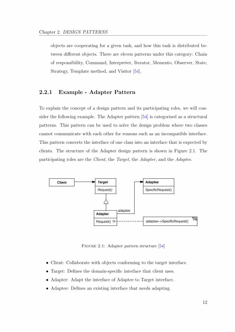
2.2.1 Example - Adapter Pattern
To explain the concept of a design pattern and its participating roles, we will con-
sider the following example. The Adapter pattern [54] is categorised as a structural
patterns. This pattern can be used to solve the design problem where two classes
cannot communicate with each other for reasons such as an incompatible interface.
This pattern converts the interface of one class into an interface that is expected by
clients. The structure of the Adapter design pattern is shown in Figure 2.1. The
participating roles are the Client, the Target, the Adapter, and the Adaptee.
Figure 2.1: Adapter pattern structure [54]
• Client: Collaborate with objects conforming to the target interface.
• Target: Defines the domain-specific interface that client uses.
• Adapter: Adapt the interface of Adaptee to Target interface.
• Adaptee: Defines an existing interface that needs adapting.
12
Chapter 2. DESIGN PATTERNS
Figure 2.1 illustrates the Adapter patterns structure and the participating roles,
where the adapter class uses multiple inheritance to adapt one class to another.
The intent of Adapter pattern is to convert the interface of a class into another
interface. The collaboration between its roles indicates the Client calls operation
on the Adapter instance. In succession, Adpater calls the Adaptee operation that
carry out the Client request. The consequences of this collaboration have different
trade-offs. The Adapter class overrides the Adaptee behaviour. The Adaptee class
adapts to the Target by committing to a concrete Adapter [54].
2.3 The Relevance of Design Patterns
The use of design patterns is useful for program comprehension and quality improve-
ments ([54], [109], [15]). Within the context of Reverse Engineering, information
related to the presence of a design pattern is useful to understand not only the
code, but to realise also the concepts behind its design. The use of design patterns
enhances the maintainability of the source code. They help the developer to write
a more understandable and a maintainable code [54]. The understandability and
maintainability come with familiar solutions to common problems, instead of every
developer trying to solve the problem in their own way. Moreover, the use of design
patterns enhances the developer productivity and the program quality [99].
Design patterns provide repeatable solutions for software problems and make it
easier to reuse successful designs and architectures [54]. Design patterns are not
specific to programming and do not translate into a code directly like class libraries
and frameworks, which are employed directly in programming [50]. They do not
teach developers how to program, but they encapsulate the design concepts, and
provide developers with suitable problem solutions from the design aspects. They
help developers to select design alternatives as s small part of classes that make a
system reusable and avoid alternatives that compromise re-usability.
13

Chapter 2. DESIGN PATTERNS
Design patterns can improve the documentation and maintenance of existing systems
[27]. They help developers to extend and modify software architecture and source
code. They help the developer to describe the problem and its solutions. Conse-
quently, this helps the maintainers to achieved a significantly better comprehension
than the maintenance with source code alone [56]. Furthermore, design patterns
enhance communication, both among software developers, among developers and
maintainers [99]. They provide a common vocabulary to be used in the context of
software problems and solutions. They help for sharing ideas between the developers
and for gaining an understanding of design principles [27].
2.4 The Impact of Design Patterns
There is a misunderstanding that design patterns should be applied and followed
wherever possible to solve design problems. However, it is very important to judge,
when to use a pattern for a particular problem. The bad selection of design pat-
terns can produce negative effects in the software development. This is due to the
complexity that patterns introduce in the design and implementation of programs.
Several studies in the literature suggested that the use of design patterns may impact
negatively the development and maintenance activities.
• Wendorff [124] assessed the impact of patterns in some industrial projects
and showed that their impact is comprehensibility negative. Khomh and
Gueheneuc [76] performed an empirical study of the impact of the Gof de-
sign patterns on different software quality characteristics. They concluded
surprising results as reported in [75]. They found that patterns do not nec-
essarily promote re-usability, expandability, and understandability and do not
always improve the quality of programs as confirmed by Gamma et al. [54].
14
Chapter 2. DESIGN PATTERNS
• Bieman et. al. [23] examined the use of the design patterns presented in
Gamma et al. [54] to see how design patterns are applied to real software de-
velopment projects. This study explored the relationship between design struc-
tures in object-oriented software and development and maintenance changes.
They analysed four small size systems and one large size system to identify
the observable effects of the use of design patterns such as the pattern change
proneness. The results showed that some classes that play roles in design pat-
terns are more change prone than others. This indicates that design patterns
are targets for bolting things on as they are less flexible.
• Zhang and Budgen [129] analysed a large amount of empirical studies to in-
vestigate what evidence is available about how and when their use can provide
an effective mechanism for knowledge transfer about design. They found that
design patterns do not help novice developers to learn about software design.
Many developers used design patterns for their design problem and consider it
as a solution of the problem. In addition, many developer focus on the identi-
fication and the documentation of patterns instead of their experiences about
using the patterns because design patters are generated from the experiences
of the software developers.
2.5 Design Pattern Implementation
A key benefit of design patterns is the fact of reusing design instead of code [40].
The structure of design patterns focuses on the relation of classes and objects rather
than the specific code with respect to object-oriented relationships. As discussed
above in Section 2.3, design patterns are not specific to programming languages.
They provide solutions which can be described based in object-oriented design and
can be implemented in any object-oriented programming language. The examples
15
Chapter 2. DESIGN PATTERNS
in Gamma et al. [54] are in C++ and Smalltalk. However, design patterns are
applicable to many of the object-oriented programming languages.
Design patterns aim to provide an access to successful solutions when software de-
velopers face recurring problems. Design patterns have been implemented in main-
stream object-oriented programming languages like Smalltalk and C++ rather than
in procedural languages (Pascal, C, Ada) [54]. Design patterns do not focus on
coding and they are not specific methods as libraries and frameworks. They provide
something much more like a guidance for software design and maintenance. How-
ever, libraries and frameworks focus on the specific application on programming, and
they do not consider such design understandability and maintainability properties.
To explain the implementation of design patterns, we will consider the example in
Section 2.2.1. The implementation of the Adapter pattern (shown in Figure 2.1) is
straightforward and can be described as follow; The Adapter class offers an interface
between classes and objects. The Adapter pattern roles are the Client, the Target,
the Adapter, and the Adaptee. The Adapter must be a subclass of the Target and
must delegate the Client calls to a method request() of the Target class to a
method specificRequest() (with different interface) of the Adaptee class. To be
able to do this, the Adapter instance needs to be associated to the Adaptee instance.
2.6 Identification of Design Patterns
The use of design patterns in the software development started in 1990s. However,
the significance of using patterns in reverse engineering area was started with the
publication of Krammer et al. approach [80]. Afterwards, different approaches have
been proposed to detect design patterns in the source code. These approaches have
utilised the source code as a main source of information for the analysed system,
and have developed a meta-model catalogue. This catalogue contains possible for-
malisations of design patterns to be used to obtain their representations and allows
16
Chapter 2. DESIGN PATTERNS
their automatic detection. The main idea of these approaches involves analysing the
classes’ structures in order to find micro structures that are similar to the design
pattern structure as described in Gamma et al. [54].
The detection of design patterns in legacy systems is difficult [17], because each
design pattern incorporates structural and behavioural components [66]. Moreover,
each design pattern has several possible implementations, where the implementation
of design pattern may vary in the code style to represent or characterise the pat-
tern [93]. In particular, the detection of behavioural patterns is challenging, since
they are highly dynamic in nature, whereas tools often tend to rely on the source
code analysis alone. Moreover, they are hard to characterise by their code struc-
ture. Behavioural patterns rely on the identification of the responsibilities and the
collaboration between the objects at the program runtime, which cannot be simply
identified.
17

Chapter 3
BACKGROUND &
LITERATURE REVIEW
This chapter covers the main concepts related to design pattern detection process,
and reviews some of past related work. Several approaches have been proposed to
date, some of these approaches provide a tool to implement the proposed approach.
Section 3.1 discusses the design pattern detection process, and the evaluation and
measurement techniques that are currently used to evaluate the accuracy of design
pattern detection approaches. Section 3.2 reviews some of the related approaches of
design pattern detection proposed in the literature. Section 3.3 presents some of the
design pattern detection tools that involve user-level of interventions in the detection
process. The limitations and challenges of the current approaches are outlined in
Section 3.4. Finally, a summary of the chapter is given in Section 3.5.
3.1 Design Pattern Detection (DPD)
There is a wide range of design pattern detection approaches, supported or im-
plemented in different ways by several tools. Design pattern detection approaches
18
Chapter 3. BACKGROUND & LITERATURE REVIEW
usually utilise the source code as the starting point for the detection process. The
source code represents the main source of information related to the analysed system.
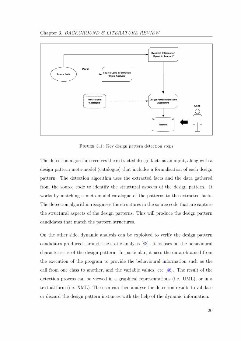
Figure 3.1 illustrates the process performed by most of the currently available de-
sign pattern detection tools along with the key steps of their detection techniques.
The process starts from the source code of the analysed system as the main source
of information about the legacy system, where the legacy system documentation is
often lacking or lost [119]. The source code is parsed into an independent intermedi-
ate representation such as the Abstract Syntax Tree (AST) or the Abstract Syntax
Graph (ASG), and then two types of analyses are required:
• Static Analysis: for program structure.
• Dynamic Analysis: for program behaviour.
The result of Static/Dynamic analysis of the source code contains:
• Structural information: inheritance/association etc.
• Behavioural information: this is a call from one class to another class, variable
values, and object identities etc.
The detection algorithm receives the extracted design facts as an input, along with
the design pattern meta-model (catalogue) that includes the formalisation of each
design pattern as described in Gamma et al. [54]. Thus, it performs a matching
process between the meta-model and the extracted facts. The results of the detection
process can then be viewed in graphical representations (UML) or in a textual form
(XMl) [14]. In detail, the design pattern detection process starts by parsing the
source code to extract the design facts in order to build a model of the system. This
model extracts all the static facts from the source code. The static analysis focuses
on the structural aspect of the source code such as the inter-class relationships
(i.e. association, aggregation, etc.). It is often useful to transform the extracted
information from the source code into an independent intermediate representation
(such as the abstract syntax tree (AST)) that helps to simplify the analysis process.
19
Chapter 3. BACKGROUND & LITERATURE REVIEW
Source Code
ParseSource Code Information
‘’Static Analysis’’
Dynamic Information‘Dynamic Analysis’’
Design Pattern Detection Algorithms
Meta-Model‘’Catalogue’’
Results
User
Figure 3.1: Key design pattern detection steps
The detection algorithm receives the extracted design facts as an input, along with a
design pattern meta-model (catalogue) that includes a formalisation of each design
pattern. The detection algorithm uses the extracted facts and the data gathered
from the source code to identify the structural aspects of the design pattern. It
works by matching a meta-model catalogue of the patterns to the extracted facts.
The detection algorithm recognises the structures in the source code that are capture
the structural aspects of the design patterns. This will produce the design pattern
candidates that match the pattern structures.
On the other side, dynamic analysis can be exploited to verify the design pattern
candidates produced through the static analysis [83]. It focuses on the behavioural
characteristics of the design pattern. In particular, it uses the data obtained from
the execution of the program to provide the behavioural information such as the
call from one class to another, and the variable values, etc [46]. The result of the
detection process can be viewed in a graphical representations (i.e. UML), or in a
textual form (i.e. XML). The user can then analyse the detection results to validate
or discard the design pattern instances with the help of the dynamic information.
20
Chapter 3. BACKGROUND & LITERATURE REVIEW
3.1.1 Classification of the literature in DPD
Many research efforts were made to date in order to develop and implement tools to
understand the legacy software systems through the recovery of the design pattern
from the source code. As discussed in Section 3.1, the typical detection process
comprises a set of key steps including: the analysis type (static, dynamic, or combi-
nation of both), the detection algorithm (i.e: CSP-based, Graph-based, fuzzy logic,
etc), and the representation types of the analysed system (XML, UML, etc). For
the ease of disposition, existing literature were classified into two interrelated fields:
Recovery, and Formalisation.
3.1.1.1 Recovery
The general problem in the area of design pattern detection is building an effective
approach that can detect the design patterns from the source code. This problem
has been extensively studied over the past twenty years [35, 41, 77, 82, 110]. Many
approaches and tools have been developed. Some of the well-known approaches that
are relevant to the approach proposed in this thesis are reviewed in Sections 3.2.
3.1.1.2 Formalisation
As discussed above, detection algorithms receive extracted design facts as inputs,
along with a design pattern meta-model (catalogue) that includes a formalisation of
each design pattern. The GoF [54] design pattern formalisation is an informative
definition to represent the design patterns structure. It is used to understand the
design pattern principles, and to teach the user how to apply the design patterns
in order to solve the common software problems. Thus, many studies in the lit-
erature adapted the building meta-model that represent the formal design pattern
specifications. Many of the design pattern detection approaches developed to date
are concerned with building formal specifications of the design patterns that capture
21
Chapter 3. BACKGROUND & LITERATURE REVIEW
the structural and the behavioural features. These approaches are concerned with
defining a set of meta-entities from which a design pattern description is obtained
[8]. A considerable amount of literature has been published on building a design
pattern formalisation.
Elaasar et al. [45] defined a formal specification for design patterns based on the
Meta-Object Facility (MOF) Specification language. Each design pattern is for-
mulated with the visual pattern modeling language (VPML), which is similar to
the UML class diagram, with the ability to specify the design pattern abstraction
through the use of object constraint language (OCL) contextual properties.
Mens and Tourwe [88] developed a framework to formulate the design patterns using
declarative meta-programming. This approach uses a logic programming language
SOUL to formulate the patterns, and to specify their constraints. It further supports
the design pattern evolution transformations (re-factoring and pattern merge).
Bayley and Zhu [19] defined a meta-modelling approach for the formal specification
of the design patterns based on a first-order predicate logic (FOL). Their design
pattern formulation provides a specification for the structural and the behavioural
features for all the GoF patterns.
3.1.2 Measurement & Evaluation
A large numbers of design pattern detection tools and approaches were proposed
to date that are based on different detection techniques. The ultimate goal for all
of these approaches is to produce high pattern detection accuracy rates. Therefore,
there is a need to evaluate these approaches in terms of detection accuracy for
comparison. In the following, a description of the Precision & Recall, weighted
F-Score, and Role-based pattern evaluation:
22
Chapter 3. BACKGROUND & LITERATURE REVIEW
3.1.2.1 Precision & Recall
Design pattern detection techniques are usually evaluated using precision (P ) and
recall (R) [96]. The precision and recall measurement were developed for the mea-
surements of the natural language, i.e. in terms of Information Retrieval [121]. The
relationship between P and R determines the accuracy of any detection approach.
Ideally, a design pattern detection approach should have good precision and recall
rates, where P values should remain high as R values increases. In this measurement,
there are three possible outcomes for detecting the pattern occurrence including:
• True Positive (TP): The detected pattern instance is implemented in the source
code. This indicates the number of real instances of the design pattern imple-
mented and identified by the pattern detection tool.
• False Positive (FP) The detected pattern instance is not implemented in the
source code. This indicates the number of instances detected by the tool but
which are not correctly implemented in the in the source code.
• False Negative (FN) The pattern is not detected but it is implemented in the
source code. This indicates the number of pattern instances implemented in
the source code which cannot be detected by the pattern detection tool.
A good and effective design pattern detection approach is ought to have a high rate
of true positives TP and a low rate of false positives FP and false negatives FN.
Based on the these outcomes, the precision and recall can be derived as follows:
• The Precision measures what proportion of the detected pattern instances
are correctly implemented in the source code. It can be calculated using the
following formula [95].
P =TP
TP + FP(3.1)
23

Chapter 3. BACKGROUND & LITERATURE REVIEW
• The Recall measures what proportion of the actually implemented pattern
instances are detected by the tool. It can be calculated using the following
formula [95].
R =TP
TP + FN(3.2)
3.1.2.2 Weighted F-Score
The use of precision and recall measurement is challenging since the increase in the
precision values is often related to the decrease in the recall values and vice versa.
Subsequently, Pettersson at al. [95] found that the precision and recall must be
assessed in combination not individually. They proposed a standard solution to use
the weighted harmonic mean of the precision and recall (weighted F-Score) as a
complement to P & R values, which can be calculated as:
Fw =(1 + w2)PR
w2P + R,w = 2
√2 ≈ 2.8 (3.3)
The suggested value of w ≈ 2.8. With this weight, the highest F-Score is obtained,
if both the precision and the recall are high. A precision of 100 percent with a recall
of 100 percent, will give an Fw of 100 percent. A precision of 100 percent with a
recall of 50 percent result in a value of Fw of 61 percent. In contrast, a precision of
50 percent with a recall of 100 percent give an Fw of 72 percent. Thus, Pettersson at
al. [95] proposed to use this weighted F-Score as a complement to P and R values.
3.1.2.3 Role-Based Pattern Evaluation
As discussed in Section 2.2, each design pattern consists of a set of multiple roles.
Although this is true, there are only few key-roles that can uniquely characterise the
design pattern (e.g. the Adapter, and the Adaptee roles in the Adapter pattern).
The non-key roles are the roles that do not affect the occurrence of their design
patterns in the source code (e.g. Adapter pattern non-key roles are the Client and
24
Chapter 3. BACKGROUND & LITERATURE REVIEW
the Target). The set of the detected roles are known as “the occurrence type” and
the number of the detected roles are known as “the occurrence size” [95].
Generally, the detection result is represented as a set of the participating classes and
interfaces with respect to the roles described in Gamma et al. [54]. Pettersson at
al. [95] found that the precision values of the detected patterns are decreased when
more roles of the pattern (occurrence size) are considered. Therefore, they proposed
the use of different occurrence types to represent the detected patterns based on the
pattern key-roles. Role-based pattern evaluation adapts the classical precision and
recall metric. Instead of focussing purely on the exact detection of an entire pattern
instance, they assumed that the evaluation should be carried out in terms of the
proportion of the correctly assigned roles per pattern.
The detected pattern instances (occurrence type) can contain all the design pattern
roles as described in Gamma et al. [54]. However, only the key-roles can uniquely
determine a design pattern. Nevertheless, after detecting the key-roles, the non-
key roles can be detected easily as they usually closely related to the key-roles.
Furthermore, the consideration of the smaller occurrence type makes the results
more comparable to other approaches.
3.1.2.4 P-MARt Pattern Repository
P-MARt [59] (Pattern-like Micro-Architecture Repository) is a repository of classes
forming micro-architectures similar to the design patterns. This repository works
as standard benchmark that helps in quantitatively analysing the results of the
current design pattern detection approach results. In fact, the lack of standard
benchmarks of design pattern instances makes the evaluation process challenging
[95]. Most of the approaches in the literature to date were evaluated manually
based on the evaluator judgement. However, some of the design pattern instances
can be considered as a true positive by an evaluator and as a false negative by
25
Chapter 3. BACKGROUND & LITERATURE REVIEW
another evaluator. Consequently, the peer reviewed patterns P-MARt repository
was proposed as a standard comparison benchmarks.
P-MARt was built based on the manual investigation of several software systems to
find micro-architectures similar to design patterns. In particular, P-MARt repos-
itory team [63] created this repository using different sources including: i) some
studies in the design pattern literature, such as the study of Bieman et al. [23] who
recorded the design pattern playing role classes in several C++, Java programs; ii)
the results from Ptidej design pattern detection tool (Ptidej - Pattern Trace Identi-
fication, Detection, and Enhancement in Java) [7]; iii) the students manual analyses
of Java programs, concluded from the assignment of their undergraduate course and
graduate course. Then, they validated all these micro-architectures manually before
their inclusion in the final repository. However, they do not claim that this a com-
plete repository for all micro-architectures similar to design patterns in the given
systems.
3.2 Design Pattern Detection Approaches
Table 3.1 provides a summery of all the design pattern detection approaches re-
viewed in this chapter. Many approaches and tools were proposed in the area of
design pattern detection during the last decades since the introduction of the GoF
design patterns by Gamma et al. [54] in 1995. This section covers some of the key
approaches in the literature. In order to highlight the related work that specifi-
cally relevant to the approach proposed in this thesis, the relevant design pattern
detection approaches can be classified using five categorises as follows: (Table 3.2
provides a summary of the strengths and weaknesses of each of these category)
1. Static: Static detection approaches utilise the structural aspect of the source
code to capture the pattern instances. They exploit the structural relationships
26
Chapter 3. BACKGROUND & LITERATURE REVIEW
between the classes that can be extracted from the source code to recognise
the design pattern structures in the source code. Section 3.2.1 presents some
of the well-known static approaches.
2. Static/Dynamic: Some approaches combined the static analysis with dy-
namic information to improve the accuracy of the detection results. These
approaches utilise the run-time information, and rely on the availability of
a representative set of program executions in order to capture the pattern
behavioural aspects in the source code. Section 3.2.2 presents some of the
approaches that utilised the dynamic information in the detection process.
3. CSP-Based: CSP-Based detection approaches consider the detection process
as a constraint satisfaction problem (CSP). The approach proposed in this
thesis is intended to complement existing constraint-based pattern detection
approaches, such as DeMIMA [60] or Ptidej [7, 58, 89]. Some of the related
approaches that are built based on constraint satisfaction technique (CSP-
Based) are discussed in more detail in Section 3.2.3.
4. User integration: Some of the current approaches consider the user interven-
tions at some levels of their detection process. The user collaborates with the
detection process unlike in the traditional detection (fully-automated). These
approaches combine the automatic detection process with the inputs from the
user (i.e: validate or discard the detection results). Current user integration
approaches are reviewed in Section 3.2.4.
5. Micro-structures: A micro-structure is a simple type of program construct
or arrangement that can be represented as a property of a program element
(classes, methods, and attributes, etc), or as a relation between these ele-
ments [14]. Micro-structures provide an indication for the presence of design
patterns inside the code. This enables the users to validate or discard the
results provided by the design pattern detection tools. Some of well-known
micro-structures in the literature are presented in Section 3.2.5.
27
Chapter 3. BACKGROUND & LITERATURE REVIEW
Approach Technique Tool Experimentation Analysis Languages
Kramer et al. [80] Prolog-Based PAT NME/ LEDA/ZAPP/ ACD
Static C++
Shi and Olsson[110]
Data flow & con-trol flow
PINOT ANT/ JavaAwt/JHotDraw/JavaSwing
Static Java
Dong et al. [39] Matrix & weight DP-Miner JavaAwt/ JHot-Draw/ JUnit/JEdit
StaticDynamicSemantic
Java
Kaczor et al. [72] Bit-vector - JHotDraw/ Juz-zle/ QuickUML
Static Java
DeLucia et al. [33] Visual languageparsing & codeinstrumentation
- JHotDraw StaticDynamic
Java
Heuzeroth et al.[69]
Prolog-Based/runtime
- JavaSwing StaticDynamic
Java
Hayashi et al. [68] Prolog-Based/Meta-patterns
Implemented asEclipse plug-in
Sample programs StaticDynamic
Java
Wang and Tzer-pos [122]
REQL query/ or-dered RSF
DPVK EffileVisison/Sample code
StaticDynamic
Eiffel
Wendehals andOrso [123]
Finite Automata - Java SWT StaticDynamic
Java
Tsantalis et al.[117]
Graph-Based DPD-tool JHotDraw/JRefactory/JUnit
Static Java
Keller et al. [74] UML visualisation SPOOL Three industrialC++ systems/ET++
static JavaC++Smalltalk
Binun and Kniesel[24]
Control flow/Data flow
DPJF JHotDraw/Java IO/ JavaAWT/ ArgoUML/Teamcore
StaticDynamic
Java
Rasool et al. [104] SQl-queries DRT-tool Examples/ JHot-Draw/ ApacheAnt
Static Java
Alnusair et al. [10] Ontology-based Sempatrec JUnit/ JHot-Draw/ JRefactory
StaticSemantic
Java
Niere et al. [93] Fuzzy reasoning Fujaba Java AWT/ JGLlibraries/
Static C++Java
Balanyi and Fer-enc [16]
XMl matching - JiKes/ Leda/StarofficeCalc/StarofficeWriter
Static C++
Rasool et al. [103] Feature-Based - JUnit/ JHot-Draw/ JRefactory
Static C++Java
Gueheneuc andAntoniol [60]
CSP-Based DeMIMA JHotDraw/JRefactory/JUnit/ Map-perXML/QuickUML
StaticDynamic
Java
El-Boussaidi et al.[44]
Constraint-Based - Sample inputs Static Java
Von Detton et al.[120]
ASG/UMLsequence
Reclipse Java AWT/ JGLlibraries/ SWT/JHotDraw/ JUnit
StaticDynamic
Java
De lucia et al. [34] Structural proper-ties/ runtime
ePAD JHotDraw StaticDynamic
Java
Table 3.1: Summary of the literature review
28
Chap
ter3.
BA
CK
GR
OU
ND
&L
ITE
RA
TU
RE
RE
VIE
W
Approach Description Strength Weaknesses
Static These approaches exploit the structural relationships between the classes that can be extracted from the source code to recognise the design pattern structures in the source code.
These approaches utilise the structural aspect of the source code to capture design pattern instances, by focusing on the inter-class relationships and their dependencies.
- The detection results acquired by static analysis approaches show high rate of false positives (FP) and false negatives (FN). - Static approaches are incapable of precisely detecting the design patterns that share the same structural aspects.
Dynamic These approaches combine the static analysis with dynamic information to improve the accuracy of the detection results. These approaches utilise the run-time information, and rely on the availability of a representative set of program executions in order to capture the pattern behavioural aspects in the source code.
- Design pattern detection approaches exploit the dynamic information to improve their detection results by reducing the false positives (FP) rate. However, The dynamic analysis appropriates with small number of execution traces (number of candidate classes). - Dynamic analysis is effective in identifying behavioural patterns, but mainly when the design pattern detection tool is supported by a complete and representative set of test cases for the analysed system.
- The main difficulty in the dynamic analysis is the implementation variants of design pattern, where each pattern can have various possible implementations for the same expected behaviour. - Dynamic analysis approaches capture the system behaviour, but it is unable to verify the intent of the design pattern. - Dynamic analysis produces many false positives (FP) when the number of classes increases.
User integration
The user integration approaches consider the user interventions at some levels of their detection process. The user collaborates with the detection process unlike in the traditional detection (fully-automated).
- These approaches combine the automatic detection process with the inputs from the user to validate or discard the detection results.
- The user of the tool has to spend much more time to discard the false positive than to trace the correct design patterns.
Micro-Structures
A micro-structure is a simple type of program construct or arrangement that can be represented as a property of a program element (classes, methods, and attributes, etc.), or as a relation between these elements.
- Micro-structure provides an indication for the presence of design patterns inside the code. This enables the users to validate or discard the results provided by the design pattern detection tools.
- The use of such kind of micro-structures alone is not enough to enhance the detection results and might increase the complexity of design patterns in the source code.
Table 3.2: Related work strengths and weaknesses
29
Chapter 3. BACKGROUND & LITERATURE REVIEW
3.2.1 Static Analysis
Tsantalis et al. [117] proposed a graph-based approach for detecting patterns. This
approach computes similarity scores between the graph vertices. They introduced a
similarity measure between the matrices representing either the systems or the de-
sired patterns. The directed graph can be built from the class diagram and mapped
into a square matrix representation. This representation is matched using a similar-
ity scoring algorithm against the design pattern descriptions. The similarity scores
are reported to the user, with the purpose of giving the user an idea about the
amount of matching.
Kramer et al. [80] proposed a knowledge-based approach based on Prolog rules
detection. It extracts the design information from a C++ code and uses the Prolog
rules to recover the design patterns. In particular, the source code is represented as
a set of Prolog facts, and the design patterns are described as the Prolog predicates
that are derived from the design patterns definitions in Gamma et al. [54]. Thus,
Prolog queries are applied to detect instances of design patterns. This approach is
limited to detect the Gof structural design patterns [54].
Shi and Olsson [110] proposed an approach based on a static program analysis which
utilises the inter-class relationships in order to detect patterns. Furthermore, they
proposed a new classification for all the GoF patterns in the context of reverse
engineering. In this approach, they analysed the abstract syntax tree (AST) of the
method bodies in order to build the control flow graph (CFG) for program elements.
Then, the (CFG) is analysed to verify the presence of a pattern. They detected all
the GoF [54] design patterns from the source code but with large number of false
positives and false negatives.
Kaczor et al. [72] proposed an approach to detect patterns by formulating the
design pattern detection as an approximate string matching using the bit-vectors
algorithm [91]. They expressed the pattern detection with operations on finite sets
30
Chapter 3. BACKGROUND & LITERATURE REVIEW
of bit-vectors. The bit-vector algorithm searches for the exact and the approximate
patterns instances by performing specific operations on the finite sets of the bit-
vectors. The design patterns and the analysed source code are expressed in terms of
string representations, which are represented by classes and their relationships (as-
sociation, aggregation, composition, instantiation, inheritance ). In particular, their
algorithm matches the string representations of design patterns and the analysed
source code by performing operations on finite sets of bit-vectors. They conducted
an experiment to detect the abstract factory and the composite design patterns.
3.2.2 Static/Dynamic Analysis
De Lucia et al. [33] proposed an approach to detect the behavioural patterns, which
combines the static and dynamic analysis. Firstly, static analysis is conducted in
order to capture the structural aspects of the design pattern. This phase produces
a set of candidate patterns. Then, the dynamic analysis is conducted on these
candidates by tracing the calls of the methods at a program run-time. This approach
is further extended by De Lucia et al. [35], they enhanced the approach of De Lucia
et al. [33] by using a model checker to improve the design pattern candidates that
are produced in the first phase (static analysis).
Heuzeroth et al. [69] proposed a detection approach that specifies the properties
of the design patterns as predicates. The detection process is performed in terms
of queries derived from the pattern specification. In particular, static analysis is
performed on the abstract syntax tree (AST) in order to produce a set of candidates
that match the patterns static rules. Then, the dynamic analysis takes these candi-
dates as an input, to check whether each candidate does match the dynamic design
pattern rules, and then accepts or rejects this candidate accordingly.
Hayashi et al. [68] introduced an approach based on static and dynamic analysis.
The static analysis extracts the design facts such as the classes, the methods, etc.
31
Chapter 3. BACKGROUND & LITERATURE REVIEW
These facts are then represented as facts in Prolog. The detection works as a Prolog
program by matching the facts with a set of conditions that satisfy a particular design
pattern. These conditions are defined as the Prolog rules. In dynamic analysis, the
source code is executed to extract the execution records.
Wang and Tzerpos [122] proposed a design pattern detection approach for Effiel
systems. Their approach describes each design pattern using its static structure and
dynamic behaviour. In the static analysis phase, they use REQL [126] scripts to
characterise the static structure of the source code. The detection matching is based
on the structural definition of each design pattern. Then, they refine the detected
instances against the behaviour definition of the design pattern, which is described
in Rigi standard format (RSF). The final stage in this approach is the manual
evaluation by the user. The user can manually verify and justify the candidate
instances by filtering out the detection results, and determining undetected design
pattern instances.
Wendehals and Orso [123] proposed a detection approach that combines the static
analysis approach proposed by Niere et al. [93] with dynamic analysis. It utilises
an automaton to represent the behavioural properties of the design patterns. The
automata are manually acquired from the behavioural patterns. The dynamic anal-
ysis then watches the methods invocation during the execution, of the source code,
and matches these invocations against the acquired automata. They verified the
feasibility of their approach by detecting the State and Strategy patterns.
Dong et al. [39] proposed an approach to detect design patterns based on the use of
matrix and weight. The detection process includes several analysis phases including
structural, behavioural, and semantic. In particular, they built a matrix of the source
code of the analysed system in the structural analysis phase. The source code classes
are represented in rows and columns and the relationships between the classes are
represented as a value in a matrix. Likewise, the design patterns are described as
matrices and weights that derived from the GoF design pattern specifications [54].
32
Chapter 3. BACKGROUND & LITERATURE REVIEW
The detection algorithm works by matching the metrics and weights in arithmetic
computations. The behavioural analysis checks method delegations and dependency
links between classes as well as checks if a class delegates the method call. In the
semantic analysis some naming conventions are verified. It explores the pattern
related knowledge from the naming conventions of each class for indications of the
roles that the class may play in the potential patterns. For example, a class with its
name including ”State” is highly likely to be part of the State pattern.
3.2.3 Constraint Satisfaction Problem & Pattern Detection
A constraint satisfaction problem (CSP) [116] can be represented as a set of variables
and set of constraints that bounds the combination of concrete values of the variables
in a specified domain. It is denoted by the triple <Variable (V), Domain (D), and
Constraint (C)> where:
• V is a set of variables v1, . . . , vn
• D represents the set d1, . . . , dn of the domains of the values such that every
vi ∈ V is represented by di ∈ D.
• C represents a set of constraints c1, . . . , cm, where each constraint limits the
values in D that can be taken by variables in V .
• A solution of such constraint satisfaction problem is a complete assignment of
variables s : vj → dj, which satisfies the constraints in C.
When considering the constraint satisfaction problem (CSP) from the perspective of
design pattern detection [7], the domain is the source code of the analysed system,
and the variables are the elements of the various design patterns that need to be
detected. The relationships between the design pattern elements that constitute a
particular design pattern are captured in the form of constraints. The solution of
such CSP (in terms of design pattern detection) maps the design pattern elements
to their corresponding elements in the source code of the analysed system.
33
Chapter 3. BACKGROUND & LITERATURE REVIEW
Rudolf [106] proposed an approach to translate graph matching problem into equiva-
lent constraint satisfaction problem. In this approach, each node and each arc of the
graph is mapped to a distinct variable. For each node variable, the domain is the set
of nodes in the target graph. For each edge variable, the domain is the set of edges
in the target graph. The restrictions of a graph are expressed using constraints.
Later, El-Boussaidi et al. [44] proposed an approach to apply Rudolf’s approach
[106] to describe the design pattern detection problem using the constraint satisfac-
tion technique. They utilised the explicit representation of the design patterns and
a meta-model of the design patterns specification in Gamma et al. [54].
Albin-Amiot et al. [7] proposed a design pattern detection approach, that is further
developed by Gueheneuc et al. [89]. This approach examines the detection process
as a constraint satisfaction problem. This approach solves the detection problem
given by matching the actual source code structure to the design pattern structure.
In particular, the problem domain is derived from the source code of the analysed
system, while the constraints and the variables are derived from the design pattern
abstract model. In this work, they introduced a meta-model Pattern Description
Language PDL to describe and formalise the design patterns abstract model. Then,
they used an explanation-based constraint solver called Palm [71] to solve the CSP
problem. It detects the micro-architectures that are identical or similar to the design
pattern in the source code. This approach detects the distorted micro-architectures
of the design patterns in the source code. Thus, the detected instances of patterns
were associated with a similarity rate. Furthermore, they use Java extended language
(JavaXL) to modify the source code to comply with a design pattern description, this
makes the distorted versions compliant with the design pattern models. Later, the
improved approach of Gueheneuc et al. [65], uses the program metrics (such as the
size, the cohesion, and the coupling) and machine-learning algorithm to fingerprint
the participating roles (classes) of a design pattern.
Gueheneuc and Antoniol [60] proposed a multi-layered approach to detect the micro-
architectures (motifs) similar to the design patterns in the source code. A motif is
34
Chapter 3. BACKGROUND & LITERATURE REVIEW
typically a class diagram describing the solution to the recurring problem addressed
by a design pattern. The first layer aims to obtain an abstract model of the source
code. This model is expressed using a meta model inspired by UML, and includes all
the constituents found in the object-oriented Java code: classes, method, inheritance,
etc. The second layer aims to describes the system at a higher level of abstraction,
it provides a model of the source code using the binary class relationship such as:
the association, the aggregation, etc. The third layer aims to identify the design mo-
tifs in the abstract model. In particular, it transforms the definition of each design
pattern using a set of constraints. These constraints are then used to match the de-
sign patterns against the obtained model from the source code. This approach uses
the explanation-based constraint in order to find these micro-architectures. This
approach exploits a constraint solver, called Palm [71], to perform an exact detec-
tion. The constraint solver performs an explanation-based constraint solving. This
means that the results are paired with the list of the matched (or not) constraints.
The PADL meta-model is also used to represent the detected design motifs. Each
design motif is described in terms of the roles, the methods, the associations and the
inheritance relationships among the roles. Later, Gueheneuc et al. [61] proposed an
extended approach based on the explanation-based constraint programming. They
enhanced the approach of Gueheneuc and Antoniol [60] using numerical analysis.
3.2.4 User Integration Approaches
Binun and Kniesel [24] proposed a detection approach based on enhancing and com-
bining some variations to the output of different analysis strategies. They defined
a methodology to improve the detection accuracy for such detection strategies by
relaxing the restrictive constraints and combining the structural and the behavioural
constraints. The role of the user in this approach is just to check if the detected
design pattern candidates are incomplete. Then, the user can generate the needed
re-factoring to make the complete implementation for the candidates.
35
Chapter 3. BACKGROUND & LITERATURE REVIEW
Keller et al. [74] proposed a design pattern detection approach that splits the de-
tection process into two phases, an automatic and an interactive. Their detection
process contains two phases. In the first phase, the design pattern structure is iden-
tified, and then presented to the user as a UML diagram. They involved the user at
the end of the detection process to refine the results by confirming or deleting the
wrong candidates.
Rasool et al. [104] proposed an approach to detect the design patterns based on the
annotations of the source code of the analysed system. These annotations are used
in forward engineering to document the implemented design patterns. Annotations
allow the transfer of knowledge between the users involved in the detection process.
The user can select the specification language for theses annotations. Later, Rasool
et al. [103] proposed an approach to detect the design patterns based on the features
(structural) of the pattern. This includes the classes, the relationships, and the
method returns. They built a catalogue of formal definitions of patterns features
including the relationships between the classes, and the method return types. Then,
they applied these definitions to multiple search techniques with the purpose of
detecting design patterns. In their approach, the user can browse and highlight
the detected design patterns within the class diagrams. The user can also select the
feature type from a list of the available feature types, as well as defining new feature.
Alnusair et al. [10] proposed an ontology based approach to detect design patterns.
In this approach, the ontology formalism are used in order to characterise the con-
ceptual knowledge of the source code. The semantic rules are used to capture the
structures and the behaviours of the design patterns in the source code. The user
can relax/edit the rules using a specialised ontology editor.
Niere et al. [93] represented the source code as an abstract syntax graph (ASG). The
detection process then works by matching the graph with a set of detection rules.
This approach allows the user to annotate certain classes and to delete the inappro-
priate role assignments. The user has the capability to look at the detection results
36
Chapter 3. BACKGROUND & LITERATURE REVIEW
and mark the design patterns for deletion. In particular, the user can assign fuzzy
thresholds for the detected sub-patterns that may influence the detection results.
Balanyi and Ferenc [16] proposed an XML-based detection approach using a spe-
cific language called DPML language (Design Pattern Mark-up Language). This
approach uses DPML to describe the structural features of each design pattern in-
cluding the classes, the attributes, the operation, and the relationships. It starts by
analysing the source code in order to build the Abstract Semantic Graph (ASG).
Then, the detection process works by matching the sub-structures in the ASG with
the DPML descriptions to find the design pattern instances in the source code. This
approach offers the user the ability to modify/define the design pattern descriptions.
Later, Ferenc et al. [47] enhanced this approach by applying machine learning tech-
niques to improve the detection results.
3.2.5 Micro-structures Approaches
Micro-structures can help to identify aspects that are fundamental for the presence
of design pattern instances inside the source code. Considering patterns as compo-
sitions of simpler elements can significantly reduce the possibility of identifying the
design patterns implemented in the source code [14]. The use of micro-structures
in the detection process can be important. This is because the results of the design
pattern detection are commonly characterised by low precision. Therefore, having
means to help the user to verify the output could improve the detection results.
Different kinds of micro-structures were proposed to date in the literature. These
can have different objectives, including the design pattern detection, the identifica-
tion of common programming constructs, and the extraction of architectural rela-
tionships within the source code. The following are some of the most well-known
micro-structures in the literature:
37
Chapter 3. BACKGROUND & LITERATURE REVIEW
• Elemental Design Patterns (EDPs): EDPs represent an in between level
of abstraction among the source code and the high-level formalisation of the
design patterns [112, 113]. Each design pattern is expressed as a construc-
tion of EDPs. These EDPs capture the mechanisms that are specific to the
object-oriented programming. This includes object creation, the abstraction
of interface, the delegation, etc. EDPs represent an intermediate level between
the source code and the design patterns, reducing the design pattern detection
to the detection of EDPs. EDPs are associated to the functionalities of the
design pattern structure [14].
• Sub-patterns: A sub-pattern is an individual description of the common
structures of design patterns [92, 93]. The use of sub-patterns reduces the
pattern structure into sub-patterns which are far simpler than the same design
pattern. However, one problem is that each of these sub-patterns may have
several variants. Besides, these sub-patterns are used by other design patterns.
Sub-patterns are associated to the syntactic form of the structures of the design
patterns.
• Micro-patterns: Micro-patterns are similar to the design patterns except
that micro-patterns stand at a lower level that is closer to the implementation
level. Gil and Maman [55] proposed a catalogue of 27 micro-patterns defined
starting from classes and interfaces. They performed an analysis on the oc-
currence of micro-patterns and showed that a majority of classes follow one or
more of the design patterns in the catalogue.
• Design pattern Clues: Clues are rules defined in terms of the roles constitut-
ing each design pattern, and in terms of the micro-structures that characterise
them. Arcelli et al. [49] proposed an approach to refine and validate the
results provided by the experimentation of common design pattern detection
38
Chapter 3. BACKGROUND & LITERATURE REVIEW
tools. They manually evaluated the selected tools based on the system docu-
mentation (in case it traces the existence of design patterns within the system),
and based on the personal knowledge about design patterns.
3.3 Design Pattern Detection Tools
Several design pattern detection tools have been implemented in the literature that
provides different capabilities. However, the comparison between these tools is dif-
ficult due to the lack of a standard and a common comparatives benchmark [64].
For this reason, different comparative studies were conducted in order to investigate
these approaches. Since the focal point in this thesis is the user intervention, some
studies that highlighted the user’s role and level of intervention in the detection
process are reviewed. This section starts by presenting some of the comparative
studies for the current detection tools in Section 3.3.1, followed by a review of some
well-known tools in Section 3.3.2.
3.3.1 Comparative Studies
Bellay and Gall [21] compared four detection tools according to four functional cate-
gories including: analysis, representation, editing/browsing and general capabilities.
The analysis category illustrates the tools parsing capabilities. The representation
category characterises the tools output form. The editing/browsing category com-
pares the capabilities of the tools in terms of providing the users browsing and
navigation capabilities. The general capabilities category concerns different aspects
including the storing capabilities, the platform, and supporting multi-users.
39
Chapter 3. BACKGROUND & LITERATURE REVIEW
Arcelli et. al. [14] classified the design pattern detection tools based on the informa-
tion used during the detection process to tools that consider the “entire” represen-
tation of the design patterns, tools that consider a ”minimal” set of key structures
design patterns, and tools that consider the ”sub-components” design patterns.
Gueheneuc et al. [64] introduced a comprehensive comparative framework for cur-
rent detection tools in terms of eight categories including the context, the intent,
the users, the input, the technique, the output, the implementation, and the tool.
The concern with this comparative framework is the user and the input categories.
Under the user’s category, they compare the tools in terms of the tools’ assumption
regarding the users, such as what is expected from the user. Furthermore, under the
input category, their framework compares the tools in terms of the required inputs,
such as what input does the detection tool accept.
3.3.2 Tools with User Capabilities
The following is a review of the most common design pattern detection tools that
involve a user level of interventions in their detection process.
ePAD - Eclipse plug-in for Design Pattern Analysis and Detection [34]. ePAD is
implemented as an Eclipse plug-in. It encloses two main detection phases; the
structural analysis phase takes the source code of the system under study as
input in order to extract the UML class diagram. Then, creates a textual
representation of this diagram. The detection process works by matching this
representation with the design patterns definitions library. The behavioural
phase takes these candidates as inputs and validates them against the design
pattern behaviour specification. This tool provides visualization feature of
the detected pattern instances as a class diagram. This feature supports the
user intervention in the analysis of the detection results. The users can access
the source code of the classes participated in the detected pattern instances
40
Chapter 3. BACKGROUND & LITERATURE REVIEW
to analyse/re-factor it. For example, the user can assign an instance as false
positive.
Reclipse - Reclipse is a Reverse Engineering tool suite based on FUJABA [120].
Reclipse tool works as a plug-in for the Eclipse IDE [1]. The Reclipse tool
identifies the structure of the design patterns graphically, and, if applicable,
identifies the design patterns behaviour in order to verify the detected candi-
date instances. Reclipse allows to graphically specify the patterns’ structure
and its behaviour to inspect the obtained candidate instances. It allows the
user to annotate certain classes, and to delete inappropriate role assignments.
PTIDEJ/DeMIMA - Pattern Trace Identification, Detection, and Enhancement
in Java) [4]. Ptidej comprises a set of tools that provide different tasks with
the main aim of identifying the design patterns and enhancing the quality of
the object-oriented code. It provides the capabilities of detecting the design
pattern instances in the source code using a constraint solver. Ptidej uses the
explanation based constraint programming to identify the design patterns in
the source code. DeMIMA [60] ( Design Motif Identification Multi-layered Ap-
proach), on the other hand, is a tool implemented on top of Ptidej framework
using Java programming language. It adopts the existing libraries of Ptidej
framework to use the constraint solver. It utilises the explanation-based con-
straint programming and the constraint relaxation to identify the complete
(or the approximate) micro-architectures, similar to the design patterns. In
this tool, the user must be familiar with the analysed system source code and
can provide explanations on the detected design pattern candidates. More-
over, this tool allows the user to relax the detection constraints to provide
approximate occurrences.
DPJF - Detect Patterns by Joining Forces, DPJF is the resulting tool for the
approach of Binun and Knives [24]. DPJF is developed as a set of SWI-
Prolog modules. The role of the user in this approach is just to check if the
41
Chapter 3. BACKGROUND & LITERATURE REVIEW
detected pattern candidates are incomplete. The user then can generate the
needed re-factoring to reach the complete implementation of the design pattern
candidates.
DPD-tool - Design Pattern Detection Tool (DPD-tool) is detection tool imple-
mented in the approach of Tsantalis et al. [117]. It provides the user with a
GUI allowing it to select the software system that needs to be analysed and
to generate a list of the recovered design pattern instances.
3.4 Weaknesses of Existing Techniques
Empirical studies on the accuracy of design pattern detection approaches have re-
peatedly shown that, for certain patterns and systems, existing tools can remain
highly inaccurate [101]. There are two principal reasons for this inaccuracy. First,
certain patterns can be highly dynamic in nature, whereas tools often tend to rely
only on the source code analysis. Even if the tools do accept the runtime-information
as the input, the (undecidable) problem of identifying a suitable set of inputs to
elicit the necessary information to detect the design pattern still remains. Second,
design pattern implementations can be an approximate. The developer might have
the pattern intent in mind, but it might deviate from the corresponding pattern
specification used by the tool.
Static analysis alone is not sufficient. Static analysis can be too conservative as
it is difficult to detect the design patterns that have similar structure. Moreover,
design patterns with behavioural aspect rely on the dynamic method invocation.
In fact, dynamic analysis is relying on the availability of runtime information (i.e.
method execution), which is challenging in reality, particularity if the system under
analysis is an old system. Current design pattern detection tools tend to rely entirely
on a combination of static and dynamic code analysis. Such tools are inaccurate,
especially when the design pattern has a substantial dynamic element. The specific
42
Chapter 3. BACKGROUND & LITERATURE REVIEW
problems of design pattern detection and the key reasons for this inaccuracy are
outlined below:
• Source code analysis is inherently inaccurate:
Static source code analysis is necessarily conservative [46]. The inherent in-
ability to distinguish between feasible and infeasible runtime behaviour means
that it is impossible to, for example, accurately infer the possible runtime-
types of an object. This means that any pattern detections that are based on
static analysis alone can include a large proportion of false-positives, especially
when the design patterns in question include a substantial dynamic element.
• Dynamic analysis is inherently unsound:
Conversely to static analysis, dynamic analysis is highly precise (any observed
execution is by definition feasible), but is also inherently unsound [46]. It is
generally impossible to identify a finite sample of program executions that
are guaranteed to capture the full range of a program behaviour (especially
without any substantial a-priori knowledge of the implementation - as it is
usually the case in pattern detection).
• Patterns are often underspecified:
Patterns are underspecified since they were proposed as templates or guidelines
to solve the design problem and can be implemented using different object-
oriented programming languages [54]. Design pattern formalisation is used to
understand the design pattern principles, and to teach the user how to apply
the design patterns in order to solve common software problems [54]. However,
there can be several other properties that intuitively apply to the pattern, but
are not explicitly specified (mainly because they are presumed to be obvious
from a developer’s standpoint).
Pattern implementations inevitably deviate from the template due to its in-
trinsic generality [107]. Most design pattern detection tools use specifications
of design patterns that almost directly reflect their original templates (e.g. in
43
Chapter 3. BACKGROUND & LITERATURE REVIEW
Gamma et al. [54]). These capture the essence of what should occur within
a pattern implementation. However, they do not contain other potential vari-
ations that would probably be obvious to the developer, but are ignored by
the tool-based approaches. If one tries to address this by adding in as many
constraints as possible, there is a real risk that, for certain projects that im-
plement the patterns in non-orthodox ways, these overly strict definitions will
fail to detect many patterns.
• The intent of a design pattern can be undecidable:
Design patterns can share the same syntactical structure, but can serve com-
pletely different purposes. Determining which (if any) design pattern was in-
tended by the developer cannot be decided by an algorithm, but the invariably
requires a degree of user judgement.
These factors can often conspire to make accurate pattern detection virtually im-
possible. If the software under analysis involves complex class hierarchies, the pos-
sible runtime object types become increasingly hard to determine. If the system in
question is a library or a framework, it can become even harder to collect a ‘repre-
sentative’ set of execution traces for dynamic analysis. In this situation, behavioural
design patterns that are loosely specified but contain a substantial dynamic element
can become even harder to detect if their structure is shared by other patterns with
different intents. This is the case for the design patterns including: State, Strategy,
Bridge, Chains of Responsibility, Decorator, and Proxy [54].
3.5 Summary
Many approaches and tools used in the process of design pattern detection were
reviewed in this chapter. Based on the review of the literature in the design pattern
detection, and given the aforementioned challenges in Section 3.4, the design pattern
detection process cannot be completely automated. The set of pattern candidates
44

Chapter 3. BACKGROUND & LITERATURE REVIEW
retrieved by the automated processes does not, in general, coincide with the set
of the correct design patterns implemented in the source code. Indeed, the fully-
automated detection process will fail to retrieve all the correct design patterns, and
may also retrieve the design patterns that are not correct. Therefore, there is a need
for a hybrid approach that combines the automatic tools with the user inputs.
The use of micro-structures is motivating because the detection results are commonly
characterised by a low accuracy. Therefore, having a mean to help the user to verify
the produced output could increase the accuracy of the detection results. In addition,
considering a design pattern as compositions of simpler elements may significantly
enhance the possibility of identifying the design pattern in the source code. Micro-
structures can provide the basic information that can provide an indication for the
presence of design patterns inside the code. However, the use of such kind of micro-
structures alone is not enough to enhance the detection results. The motivation is
that the integration of the user in an iterative process helps to refine and gradually
enhances the accuracy of the detection results.
The main point of this thesis is to highlight the users’ role in the design pattern
detection process, and how this knowledge can be used to enhance the detection
results. It is important to note that the user plays a significant role in the design
detection process. No one can consider the detection process as a fully-automated
process. However, it is the semi -automated process that needs the user judgements
at the some point when the automatic means is limited. The motivation here is to
investigate the users’ knowledge, and to study the impact of this knowledge in the
design pattern detection process.
45
Chapter 4
GUIDING DESIGN PATTERN
DETECTION WITH HINTS
A new design pattern detection approach is proposed in this chapter that places
developer knowledge at the heart of the design pattern detection process. The
aim is that developer-supplied hints can counter-act the core problems discussed in
Section 3.4. Essentially, a ‘hint’ enables the developer to provide a small fact about
the system in question, or about the implementation of the patterns, which cannot
be readily derived from the source code alone.
The proposed approach seeks to enable the user to feed small ‘hints’ into the detec-
tion process. Most existing tools permit a limited degree of user-interaction. For
example, some tools allow the user to annotate certain classes, or to delete inap-
propriate role assignments. However, the approach proposed in this chapter enables
the developer to be much more expressive, whilst remaining easy to use.
Hints can provide vital information about the dynamic behaviour of the program
that might be impossible to verify from a finite number of program executions.
Hints can also provide a partial knowledge about the implementations of the de-
sign pattern. The proposed approach is intended to be compatible with existing
46
Chapter 4. GUIDING DESIGN PATTERN DETECTION WITH HINTS
(constraint-based) pattern detection approaches, to act as a complementary ‘layer’
to enable additional feedback from the developer.
Depending on the developer’s familiarity with the system, they could, for example,
assert that a particular method call certainly cannot happen (despite the fact that
it might appear in the static call graph), thanks to their knowledge of the run-time
object types. The developer could state that a particular class or method certainly
does or does not play a particular role within a design pattern. They could also,
for example, search for a stricter definition of the design pattern than is commonly
used, or only want to search for occurrences where a specific method is only ever
invoked after a call to another method.
Section 4.1 presents a motivating scenario to motivate and explain the proposed ap-
proach. Section 4.2 introduces an overview of the proposed design pattern detection
approach. Section 4.3 presents the source code analysis process used in the proposed
approach. Section 4.4 presents the mapping of design pattern detection process to
constraint satisfaction problem. Section 4.5 presents the refinement process. Section
4.6 presents the hint generation process. Section 4.7 presents the implementation
of a proof-of-concept tool. Section 4.8 presents the related work to the approach
proposed in this chapter. Finally, Section 4.9 presents a summary of this chapter.
4.1 Motivating Example
To illustrate the proposed approach, a small toy system example is presented in this
section, which is used as a running example throughout this chapter. Suppose that
the system shown in Figure 4.1 (a) is under investigation. The extracted call graph
is shown in Figure 4.1 (b). The developer is interested in detecting any instances of
Command pattern [54]. This pattern is identical in structure to the Adapter pattern
[54]. Both design patterns are identical, with a substantial dynamic element, and
47
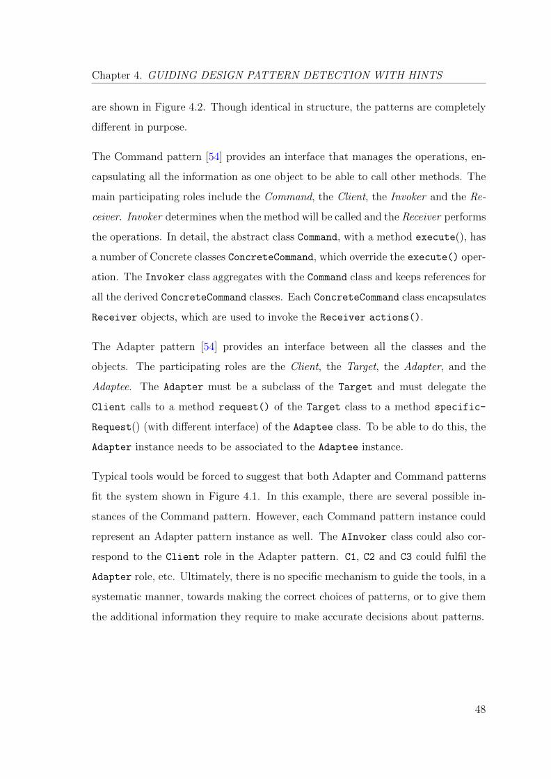
Chapter 4. GUIDING DESIGN PATTERN DETECTION WITH HINTS
are shown in Figure 4.2. Though identical in structure, the patterns are completely
different in purpose.
The Command pattern [54] provides an interface that manages the operations, en-
capsulating all the information as one object to be able to call other methods. The
main participating roles include the Command, the Client, the Invoker and the Re-
ceiver. Invoker determines when the method will be called and the Receiver performs
the operations. In detail, the abstract class Command, with a method execute(), has
a number of Concrete classes ConcreteCommand, which override the execute() oper-
ation. The Invoker class aggregates with the Command class and keeps references for
all the derived ConcreteCommand classes. Each ConcreteCommand class encapsulates
Receiver objects, which are used to invoke the Receiver actions().
The Adapter pattern [54] provides an interface between all the classes and the
objects. The participating roles are the Client, the Target, the Adapter, and the
Adaptee. The Adapter must be a subclass of the Target and must delegate the
Client calls to a method request() of the Target class to a method specific-
Request() (with different interface) of the Adaptee class. To be able to do this, the
Adapter instance needs to be associated to the Adaptee instance.
Typical tools would be forced to suggest that both Adapter and Command patterns
fit the system shown in Figure 4.1. In this example, there are several possible in-
stances of the Command pattern. However, each Command pattern instance could
represent an Adapter pattern instance as well. The AInvoker class could also cor-
respond to the Client role in the Adapter pattern. C1, C2 and C3 could fulfil the
Adapter role, etc. Ultimately, there is no specific mechanism to guide the tools, in a
systematic manner, towards making the correct choices of patterns, or to give them
the additional information they require to make accurate decisions about patterns.
48
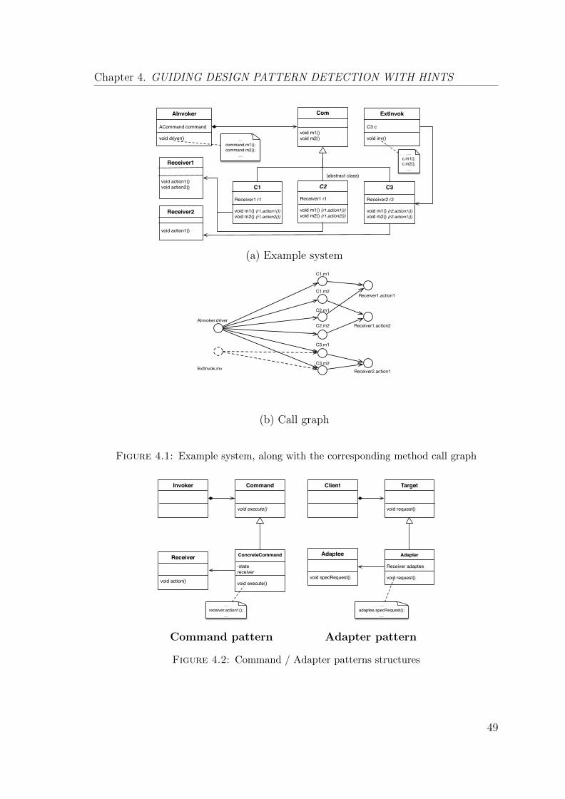
Chapter 4. GUIDING DESIGN PATTERN DETECTION WITH HINTS
AInvoker
ACommand command
void driver()
Com
void m1()void m2()
C1
Receiver1 r1
void m1() {r1.action1()}void m2() {r1.action2()}
C2
Receiver1 r1
void m1() {r1.action1()}void m2() {r1.action2()}
C3
Receiver2 r2
void m1() {r2.action1()}void m2() {r2.action1()}
Receiver1
void action1()void action2()
Receiver2
void action1()
…command.m1();command.m2();
…
(abstract class)
ExtInvok
C3 c
void inv()
…c.m1();c.m2();
…
(a) Example system
AInvoker.driver
C1.m1
C1.m2
C2.m1
C2.m2
C3.m1
C3.m2
Receiver1.action1
Receiver1.action2
Receiver2.action1ExtInvok.inv
(b) Call graph
Figure 4.1: Example system, along with the corresponding method call graph
Invoker Command
void execute()
ConcreteCommand
-statereceiver
void execute()
Receiver
void action()
…receiver.action1();
…
Client Target
void request()
Adapter
Receiver adaptee
void request()
Adaptee
void specRequest()
…adaptee.specRequest();
…
Command pattern Adapter pattern
Figure 4.2: Command / Adapter patterns structures
49
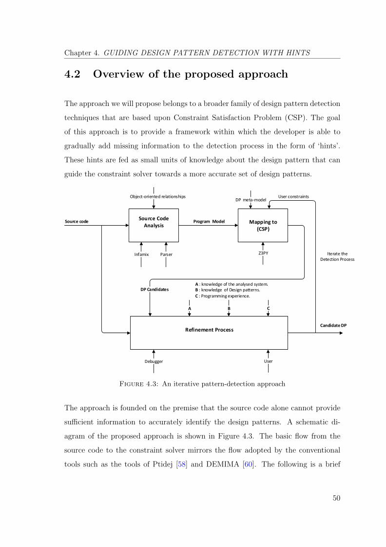
Chapter 4. GUIDING DESIGN PATTERN DETECTION WITH HINTS
4.2 Overview of the proposed approach
The approach we will propose belongs to a broader family of design pattern detection
techniques that are based upon Constraint Satisfaction Problem (CSP). The goal
of this approach is to provide a framework within which the developer is able to
gradually add missing information to the detection process in the form of ‘hints’.
These hints are fed as small units of knowledge about the design pattern that can
guide the constraint solver towards a more accurate set of design patterns.
Source Code Analysis
Infamix
Mapping to (CSP)
Parser
Program ModelSource code
Z3PY
Refinement Process
A B C
Debugger User
Candidate DP
DP Candidates
DP meta-modelUser constraints
Iterate the Detection Process
A : knowledge of the analysed system.B : knowledge of Design patterns.
C : Programming experience.
Object-oriented relationships
Figure 4.3: An iterative pattern-detection approach
The approach is founded on the premise that the source code alone cannot provide
sufficient information to accurately identify the design patterns. A schematic di-
agram of the proposed approach is shown in Figure 4.3. The basic flow from the
source code to the constraint solver mirrors the flow adopted by the conventional
tools such as the tools of Ptidej [58] and DEMIMA [60]. The following is a brief
50
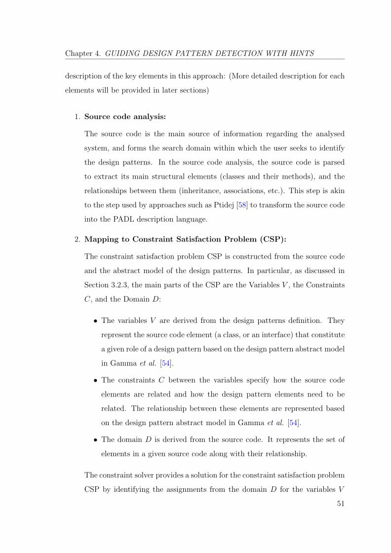
Chapter 4. GUIDING DESIGN PATTERN DETECTION WITH HINTS
description of the key elements in this approach: (More detailed description for each
elements will be provided in later sections)
1. Source code analysis:
The source code is the main source of information regarding the analysed
system, and forms the search domain within which the user seeks to identify
the design patterns. In the source code analysis, the source code is parsed
to extract its main structural elements (classes and their methods), and the
relationships between them (inheritance, associations, etc.). This step is akin
to the step used by approaches such as Ptidej [58] to transform the source code
into the PADL description language.
2. Mapping to Constraint Satisfaction Problem (CSP):
The constraint satisfaction problem CSP is constructed from the source code
and the abstract model of the design patterns. In particular, as discussed in
Section 3.2.3, the main parts of the CSP are the Variables V , the Constraints
C, and the Domain D:
• The variables V are derived from the design patterns definition. They
represent the source code element (a class, or an interface) that constitute
a given role of a design pattern based on the design pattern abstract model
in Gamma et al. [54].
• The constraints C between the variables specify how the source code
elements are related and how the design pattern elements need to be
related. The relationship between these elements are represented based
on the design pattern abstract model in Gamma et al. [54].
• The domain D is derived from the source code. It represents the set of
elements in a given source code along with their relationship.
The constraint solver provides a solution for the constraint satisfaction problem
CSP by identifying the assignments from the domain D for the variables V
51
Chapter 4. GUIDING DESIGN PATTERN DETECTION WITH HINTS
that obey the constraints C. The solution of such a CSP maps the design
pattern elements to their corresponding elements in the system. It provides
a set of elements from the given source code whose relationships satisfy the
constraints of the CSP problem.
3. Refinement Process:
At this point, the conventional design pattern detection process is accom-
plished. Inevitably (due to the reasons discussed in Section 3.4), some of the
detected design patterns will be incorrect or entirely superfluous. As shown
in Figure 4.3, the proposed design pattern detection process is iterative. The
developer has the opportunity to inspect the current proposed solution and
pick out any obvious problems. This is accomplished by, for example, inspect-
ing the source code to see whether any of the code comments or identifiers
corroborate (or contradict) a potential pattern. The developer might wish to
carry out a cursory dynamic analysis (e.g. with the help of a debugger) to, for
example, determine whether a particular method really does override another
method, or whether a class can take on a particular role in a design pattern.
The refinement information are fed back to the detection process in the form
of additional constrains.
4.3 Source Code Analysis
Generally, in traditional design pattern detection process, it is common for the
source code to be the main source of information for the analysed system. The
source code works as an input to the detection process. In this phase, the source
code is parsed to extract the design facts (classes, methods, and attributes). In
particular, the source code analysis phase produces the static model for the source
code architecture and behaviour (statically). The architecture model contains all the
classes, the methods, the attributes, and their types. The behaviour model contains
52
Chapter 4. GUIDING DESIGN PATTERN DETECTION WITH HINTS
a list of method invocations. Subsequently, these two models are then used to create
the corresponding model with respect to object-oriented relationships between the
classes such as, the inheritance, the association, etc. The goal of this phase is to
produce a model of the source code of the analysed system with respect to the
object-oriented relationships.
4.4 Mapping to Constraint Satisfaction Problem
A relatively broad family of existing pattern detection techniques treat the design
pattern detection as a constraint satisfaction problem (CSP) [7, 13, 44, 62]. A set
of constraints are used to represent the design pattern abstract model. These con-
straints are derived from the abstract models (specifications) that describe their
structure. These constraints incorporate the classes, the methods and the relation-
ships between the classes such as the inheritance, the association.
The constraint solver receives the extracted design facts as an input, along with the
design pattern constraints. It subsequently performs a matching process between the
pattern constraints model and the extracted facts. It reports all the structure that
matches the abstract model. As a result of this step, the design pattern candidates
are produced. When considering a CSP from the perspective of the design pattern
detection [7], the main parts of this CSP problem contain the variables V , the domain
D, the constraints C, and the solution. As an example of how to translate a design
pattern detection problem into a CSP, consider the running example presented in
Figure 4.1 as follows:.
4.4.1 Variables
Variables are roles in design patterns for which the goal is to find a source code
element. In particular, variables are either (a classes, or an interface) of the various
53
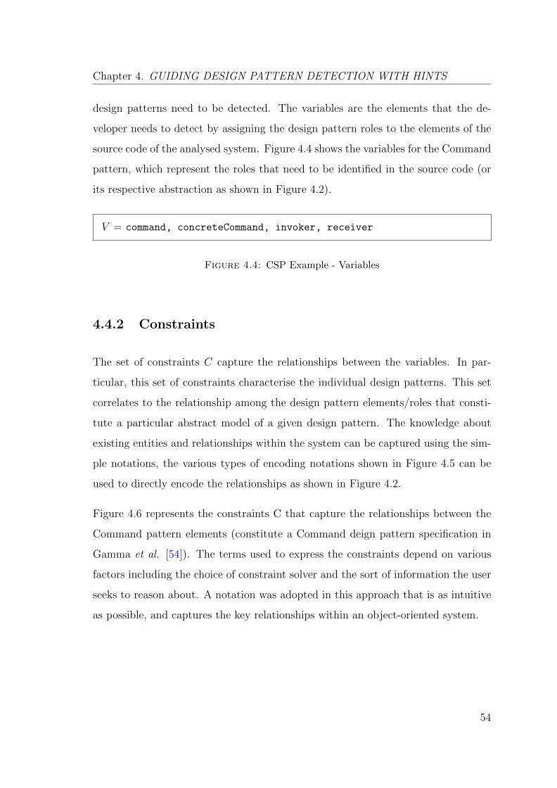
Chapter 4. GUIDING DESIGN PATTERN DETECTION WITH HINTS
design patterns need to be detected. The variables are the elements that the de-
veloper needs to detect by assigning the design pattern roles to the elements of the
source code of the analysed system. Figure 4.4 shows the variables for the Command
pattern, which represent the roles that need to be identified in the source code (or
its respective abstraction as shown in Figure 4.2).
V = command, concreteCommand, invoker, receiver
Figure 4.4: CSP Example - Variables
4.4.2 Constraints
The set of constraints C capture the relationships between the variables. In par-
ticular, this set of constraints characterise the individual design patterns. This set
correlates to the relationship among the design pattern elements/roles that consti-
tute a particular abstract model of a given design pattern. The knowledge about
existing entities and relationships within the system can be captured using the sim-
ple notations, the various types of encoding notations shown in Figure 4.5 can be
used to directly encode the relationships as shown in Figure 4.2.
Figure 4.6 represents the constraints C that capture the relationships between the
Command pattern elements (constitute a Command deign pattern specification in
Gamma et al. [54]). The terms used to express the constraints depend on various
factors including the choice of constraint solver and the sort of information the user
seeks to reason about. A notation was adopted in this approach that is as intuitive
as possible, and captures the key relationships within an object-oriented system.
54
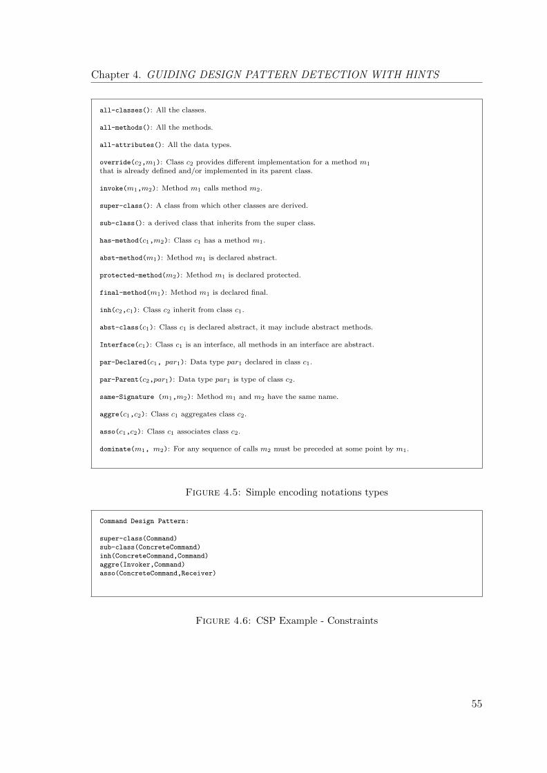
Chapter 4. GUIDING DESIGN PATTERN DETECTION WITH HINTS
all-classes(): All the classes.
all-methods(): All the methods.
all-attributes(): All the data types.
override(c2,m1): Class c2 provides different implementation for a method m1
that is already defined and/or implemented in its parent class.
invoke(m1,m2): Method m1 calls method m2.
super-class(): A class from which other classes are derived.
sub-class(): a derived class that inherits from the super class.
has-method(c1,m2): Class c1 has a method m1.
abst-method(m1): Method m1 is declared abstract.
protected-method(m2): Method m1 is declared protected.
final-method(m1): Method m1 is declared final.
inh(c2,c1): Class c2 inherit from class c1.
abst-class(c1): Class c1 is declared abstract, it may include abstract methods.
Interface(c1): Class c1 is an interface, all methods in an interface are abstract.
par-Declared(c1, par1): Data type par1 declared in class c1.
par-Parent(c2,par1): Data type par1 is type of class c2.
same-Signature (m1,m2): Method m1 and m2 have the same name.
aggre(c1,c2): Class c1 aggregates class c2.
asso(c1,c2): Class c1 associates class c2.
dominate(m1, m2): For any sequence of calls m2 must be preceded at some point by m1.
Figure 4.5: Simple encoding notations types
Command Design Pattern:
super-class(Command)
sub-class(ConcreteCommand)
inh(ConcreteCommand,Command)
aggre(Invoker,Command)
asso(ConcreteCommand,Receiver)
Figure 4.6: CSP Example - Constraints
55
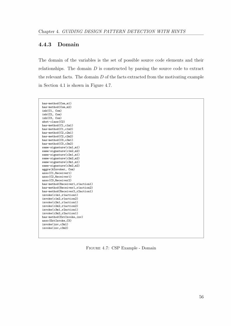
Chapter 4. GUIDING DESIGN PATTERN DETECTION WITH HINTS
4.4.3 Domain
The domain of the variables is the set of possible source code elements and their
relationships. The domain D is constructed by parsing the source code to extract
the relevant facts. The domain D of the facts extracted from the motivating example
in Section 4.1 is shown in Figure 4.7.
has-method(Com,m1)
has-method(Com,m2)
inh(C1, Com)
inh(C2, Com)
inh(C3, Com)
abst-class(C2)
has-method(C1,c1m1)
has-method(C1,c1m2)
has-method(C2,c2m1)
has-method(C2,c2m2)
has-method(C3,c3m1)
has-method(C3,c3m2)
same-signature(c1m1,m1)
same-signature(c1m2,m2)
same-signature(c2m1,m1)
same-signature(c2m2,m2)
same-signature(c3m1,m1)
same-signature(c3m2,m2)
aggre(AInvoker, Com)
asso(C1,Receiver1)
asso(C2,Receiver1)
asso(C3,Receiver2)
has-method(Receiver1,r1action1)
has-method(Receiver1,r1action2)
has-method(Receiver2,r2action1)
invoke(c1m1,r1action1)
invoke(c1m2,r1action2)
invoke(c2m1,r1action1)
invoke(c2m2,r1action2)
invoke(c3m1,r2action1)
invoke(c3m2,r2action1)
has-method(ExtInvoke,inv)
asso(ExtInvoke,C3)
invoke(inv,c3m1)
invoke(inv,c3m2)
Figure 4.7: CSP Example - Domain
56
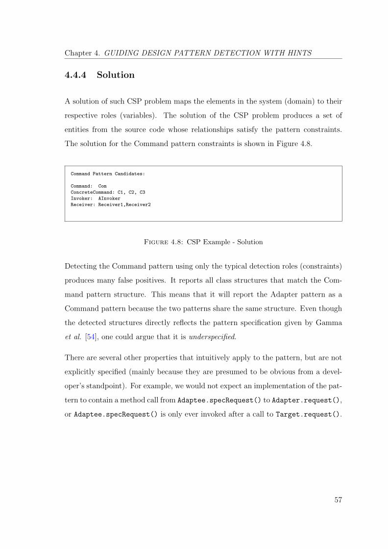
Chapter 4. GUIDING DESIGN PATTERN DETECTION WITH HINTS
4.4.4 Solution
A solution of such CSP problem maps the elements in the system (domain) to their
respective roles (variables). The solution of the CSP problem produces a set of
entities from the source code whose relationships satisfy the pattern constraints.
The solution for the Command pattern constraints is shown in Figure 4.8.
Command Pattern Candidates:
Command: Com
ConcreteCommand: C1, C2, C3
Invoker: AInvoker
Receiver: Receiver1,Receiver2
Figure 4.8: CSP Example - Solution
Detecting the Command pattern using only the typical detection roles (constraints)
produces many false positives. It reports all class structures that match the Com-
mand pattern structure. This means that it will report the Adapter pattern as a
Command pattern because the two patterns share the same structure. Even though
the detected structures directly reflects the pattern specification given by Gamma
et al. [54], one could argue that it is underspecified.
There are several other properties that intuitively apply to the pattern, but are not
explicitly specified (mainly because they are presumed to be obvious from a devel-
oper’s standpoint). For example, we would not expect an implementation of the pat-
tern to contain a method call from Adaptee.specRequest() to Adapter.request(),
or Adaptee.specRequest() is only ever invoked after a call to Target.request().
57
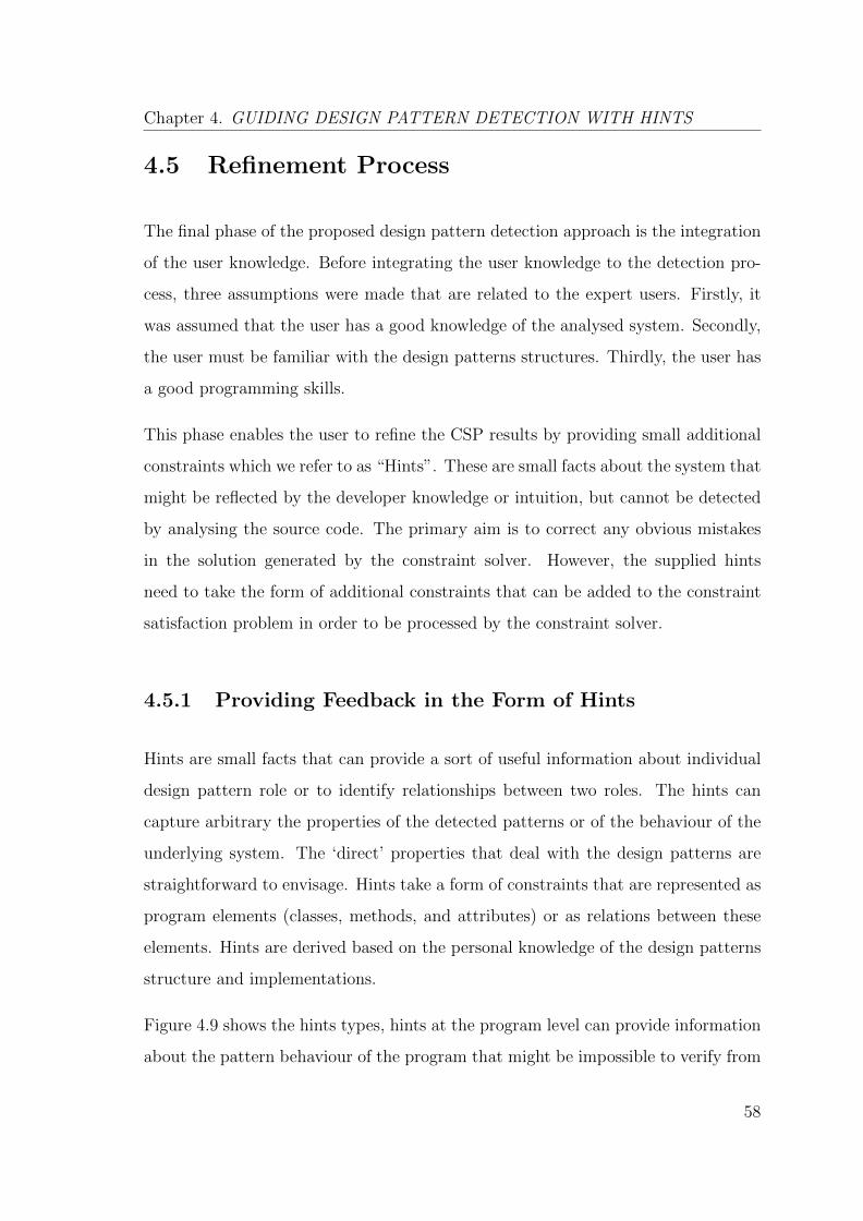
Chapter 4. GUIDING DESIGN PATTERN DETECTION WITH HINTS
4.5 Refinement Process
The final phase of the proposed design pattern detection approach is the integration
of the user knowledge. Before integrating the user knowledge to the detection pro-
cess, three assumptions were made that are related to the expert users. Firstly, it
was assumed that the user has a good knowledge of the analysed system. Secondly,
the user must be familiar with the design patterns structures. Thirdly, the user has
a good programming skills.
This phase enables the user to refine the CSP results by providing small additional
constraints which we refer to as “Hints”. These are small facts about the system that
might be reflected by the developer knowledge or intuition, but cannot be detected
by analysing the source code. The primary aim is to correct any obvious mistakes
in the solution generated by the constraint solver. However, the supplied hints
need to take the form of additional constraints that can be added to the constraint
satisfaction problem in order to be processed by the constraint solver.
4.5.1 Providing Feedback in the Form of Hints
Hints are small facts that can provide a sort of useful information about individual
design pattern role or to identify relationships between two roles. The hints can
capture arbitrary the properties of the detected patterns or of the behaviour of the
underlying system. The ‘direct’ properties that deal with the design patterns are
straightforward to envisage. Hints take a form of constraints that are represented as
program elements (classes, methods, and attributes) or as relations between these
elements. Hints are derived based on the personal knowledge of the design patterns
structure and implementations.
Figure 4.9 shows the hints types, hints at the program level can provide information
about the pattern behaviour of the program that might be impossible to verify from
58
Chapter 4. GUIDING DESIGN PATTERN DETECTION WITH HINTS
Hints
-> Class X has type Y -> Method m1 invoked before/after method m2
-> Element X plays role Y
Program Pattern
Structural Sequential
Figure 4.9: Hints level of detail
a finite number of program executions (sequential). They can also provide partial
knowledge about the design pattern implementations themselves (structural). For
example, the developer could identify a common relation between the design pattern
roles. These hints give the user more information related to single role that can be
constituted with various design patterns.
At the pattern level, the developer could state that a particular class or method cer-
tainly does or does not play a particular role within a design pattern structure. The
developer might detect a class that has been mistakenly attributed to a particular
role, and might wish to formulate a constraint that states otherwise (i.e. ‘Class X is
not an Adapter’ for example). The developer might also notice that a large number
of false positive patterns are produced because the program analysis has failed to
identify or rule-out a particular property of the source code.
All of the structural constraint types can be directly extracted by a straightforward
source code analysis. However, these fail to capture the sequential constraints on the
method calls, which can be so crucial to accurate pattern detection. Although the
invoke constraint states that method m1 invokes method m2, this does not imply
that m1 must always occur before m2. For example, in behavioural design patterns,
the sequencing of the method calls can often provide valuable evidence about the
accuracy of a pattern.
59
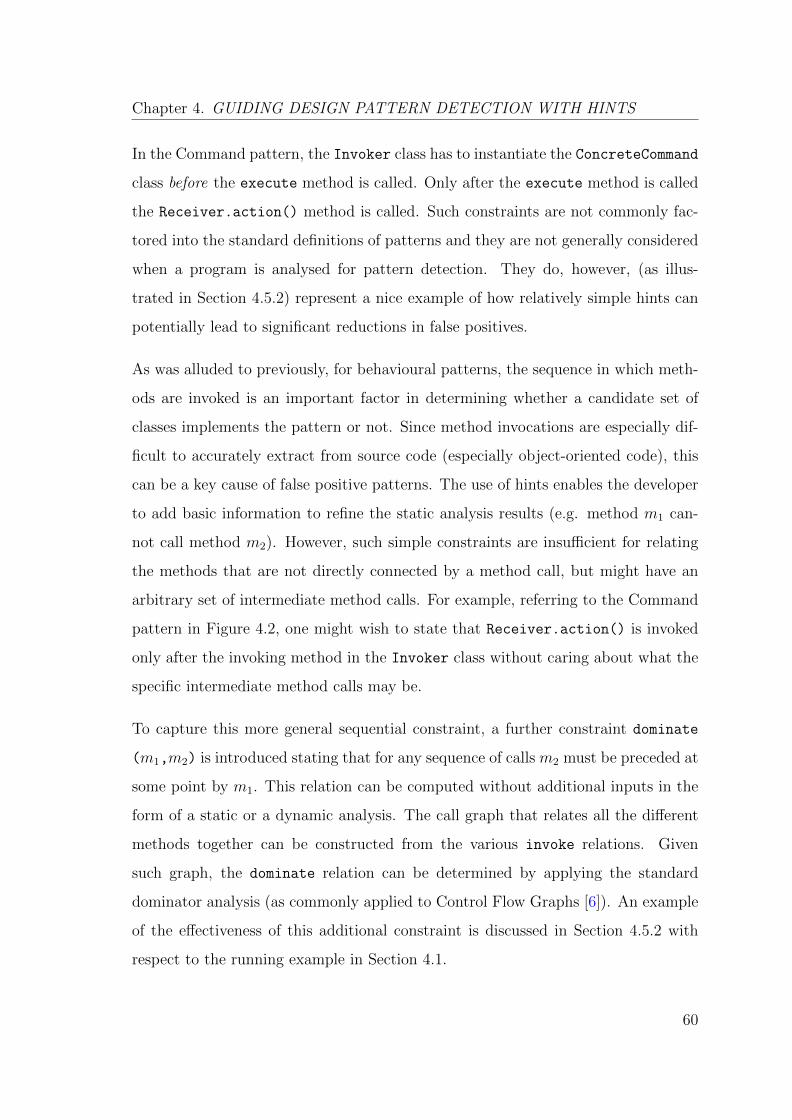
Chapter 4. GUIDING DESIGN PATTERN DETECTION WITH HINTS
In the Command pattern, the Invoker class has to instantiate the ConcreteCommand
class before the execute method is called. Only after the execute method is called
the Receiver.action() method is called. Such constraints are not commonly fac-
tored into the standard definitions of patterns and they are not generally considered
when a program is analysed for pattern detection. They do, however, (as illus-
trated in Section 4.5.2) represent a nice example of how relatively simple hints can
potentially lead to significant reductions in false positives.
As was alluded to previously, for behavioural patterns, the sequence in which meth-
ods are invoked is an important factor in determining whether a candidate set of
classes implements the pattern or not. Since method invocations are especially dif-
ficult to accurately extract from source code (especially object-oriented code), this
can be a key cause of false positive patterns. The use of hints enables the developer
to add basic information to refine the static analysis results (e.g. method m1 can-
not call method m2). However, such simple constraints are insufficient for relating
the methods that are not directly connected by a method call, but might have an
arbitrary set of intermediate method calls. For example, referring to the Command
pattern in Figure 4.2, one might wish to state that Receiver.action() is invoked
only after the invoking method in the Invoker class without caring about what the
specific intermediate method calls may be.
To capture this more general sequential constraint, a further constraint dominate
(m1,m2) is introduced stating that for any sequence of calls m2 must be preceded at
some point by m1. This relation can be computed without additional inputs in the
form of a static or a dynamic analysis. The call graph that relates all the different
methods together can be constructed from the various invoke relations. Given
such graph, the dominate relation can be determined by applying the standard
dominator analysis (as commonly applied to Control Flow Graphs [6]). An example
of the effectiveness of this additional constraint is discussed in Section 4.5.2 with
respect to the running example in Section 4.1.
60
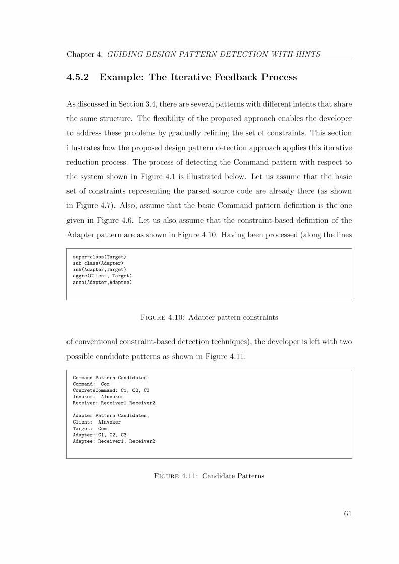
Chapter 4. GUIDING DESIGN PATTERN DETECTION WITH HINTS
4.5.2 Example: The Iterative Feedback Process
As discussed in Section 3.4, there are several patterns with different intents that share
the same structure. The flexibility of the proposed approach enables the developer
to address these problems by gradually refining the set of constraints. This section
illustrates how the proposed design pattern detection approach applies this iterative
reduction process. The process of detecting the Command pattern with respect to
the system shown in Figure 4.1 is illustrated below. Let us assume that the basic
set of constraints representing the parsed source code are already there (as shown
in Figure 4.7). Also, assume that the basic Command pattern definition is the one
given in Figure 4.6. Let us also assume that the constraint-based definition of the
Adapter pattern are as shown in Figure 4.10. Having been processed (along the lines
super-class(Target)
sub-class(Adapter)
inh(Adapter,Target)
aggre(Client, Target)
asso(Adapter,Adaptee)
Figure 4.10: Adapter pattern constraints
of conventional constraint-based detection techniques), the developer is left with two
possible candidate patterns as shown in Figure 4.11.
Command Pattern Candidates:
Command: Com
ConcreteCommand: C1, C2, C3
Invoker: AInvoker
Receiver: Receiver1,Receiver2
Adapter Pattern Candidates:
Client: AInvoker
Target: Com
Adapter: C1, C2, C3
Adaptee: Receiver1, Receiver2
Figure 4.11: Candidate Patterns
61
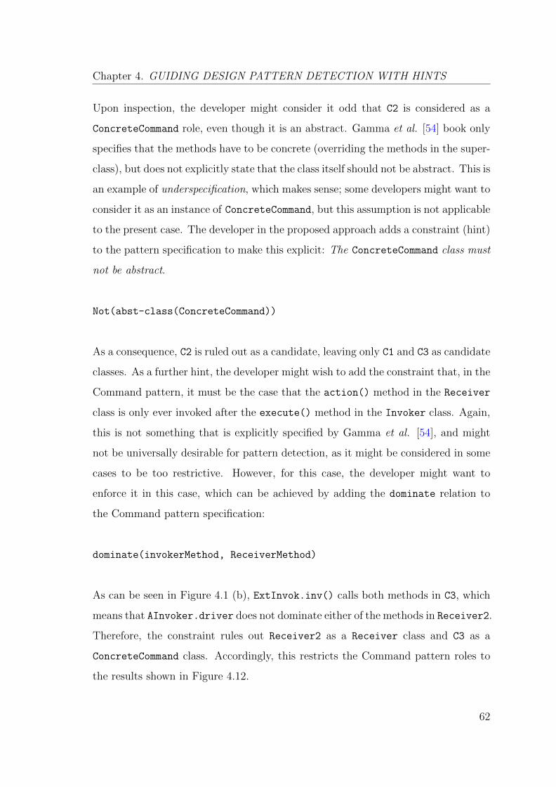
Chapter 4. GUIDING DESIGN PATTERN DETECTION WITH HINTS
Upon inspection, the developer might consider it odd that C2 is considered as a
ConcreteCommand role, even though it is an abstract. Gamma et al. [54] book only
specifies that the methods have to be concrete (overriding the methods in the super-
class), but does not explicitly state that the class itself should not be abstract. This is
an example of underspecification, which makes sense; some developers might want to
consider it as an instance of ConcreteCommand, but this assumption is not applicable
to the present case. The developer in the proposed approach adds a constraint (hint)
to the pattern specification to make this explicit: The ConcreteCommand class must
not be abstract.
Not(abst-class(ConcreteCommand))
As a consequence, C2 is ruled out as a candidate, leaving only C1 and C3 as candidate
classes. As a further hint, the developer might wish to add the constraint that, in the
Command pattern, it must be the case that the action() method in the Receiver
class is only ever invoked after the execute() method in the Invoker class. Again,
this is not something that is explicitly specified by Gamma et al. [54], and might
not be universally desirable for pattern detection, as it might be considered in some
cases to be too restrictive. However, for this case, the developer might want to
enforce it in this case, which can be achieved by adding the dominate relation to
the Command pattern specification:
dominate(invokerMethod, ReceiverMethod)
As can be seen in Figure 4.1 (b), ExtInvok.inv() calls both methods in C3, which
means that AInvoker.driver does not dominate either of the methods in Receiver2.
Therefore, the constraint rules out Receiver2 as a Receiver class and C3 as a
ConcreteCommand class. Accordingly, this restricts the Command pattern roles to
the results shown in Figure 4.12.
62
Chapter 4. GUIDING DESIGN PATTERN DETECTION WITH HINTS
Command Pattern Occurrences:
command: Com
concreteCommand: C1
invoker: AInvoker
receiver: Receiver1
Figure 4.12: Command pattern candidate
Finally, the developer might decide, upon closer inspection of the source code and
its identifiers, that Com is unlikely to be a Target class in the Adapter pattern.
Accordingly, the developer might choose to add the following constraint:
Not(Com == target)
Finally, this leaves the single Command pattern outlined above. In this example, the
constraints have exclusively been concerned with tightening up the pattern defini-
tions. However, they could just as well pertain to the system itself. If, for example,
the developer knows that one methods always dominates another methods, this in-
formation can be readily added in exactly the same manner as the hints given above.
4.5.3 Using Templates to Guide Hint Selection
The requirement that the developer can readily phrase the arbitrary hints in the form
of constraints may occasionally be unrealistic. Constructing proper constraints can
require time, effort, and some knowledge of using constraint solvers, none of which
are necessarily available. Addressing this problem is very much part of our ongoing
work. However, one key effort we have made is inspired by a solution to a similar
problem that arose in the context of software model checking.
In their work on model checking, Dwyer et al. observed that, despite their ability to
verify properties about software and hardware systems, formalisms such as Linear
Temporal Logic [97] were not used as widely as they ought to be. They addressed
63
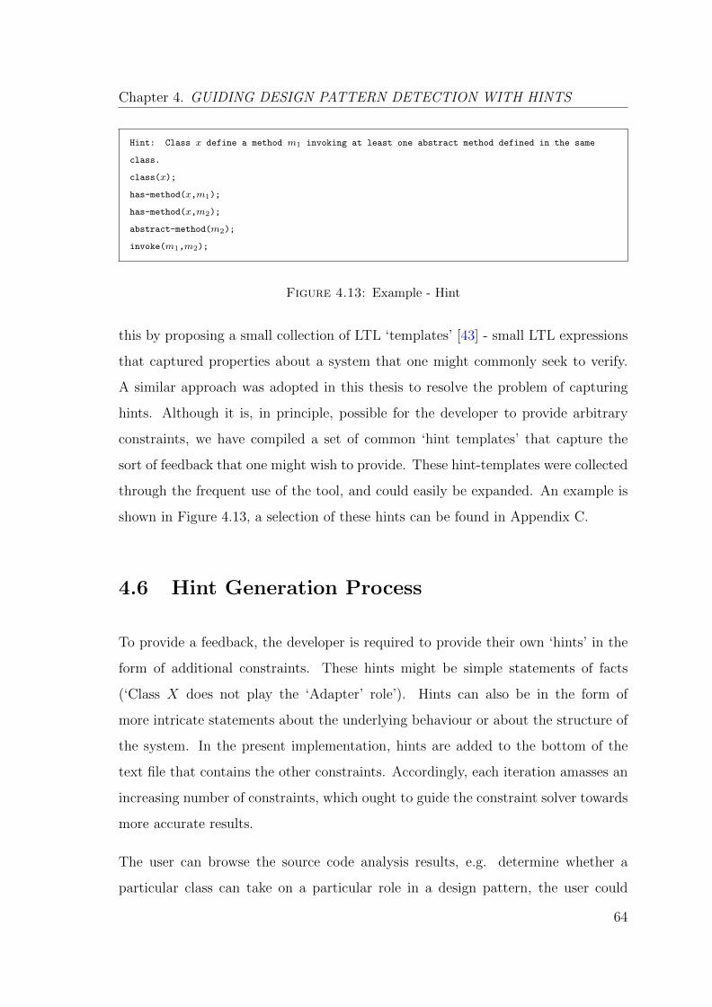
Chapter 4. GUIDING DESIGN PATTERN DETECTION WITH HINTS
Hint: Class x define a method m1 invoking at least one abstract method defined in the same
class.
class(x);
has-method(x,m1);
has-method(x,m2);
abstract-method(m2);
invoke(m1,m2);
Figure 4.13: Example - Hint
this by proposing a small collection of LTL ‘templates’ [43] - small LTL expressions
that captured properties about a system that one might commonly seek to verify.
A similar approach was adopted in this thesis to resolve the problem of capturing
hints. Although it is, in principle, possible for the developer to provide arbitrary
constraints, we have compiled a set of common ‘hint templates’ that capture the
sort of feedback that one might wish to provide. These hint-templates were collected
through the frequent use of the tool, and could easily be expanded. An example is
shown in Figure 4.13, a selection of these hints can be found in Appendix C.
4.6 Hint Generation Process
To provide a feedback, the developer is required to provide their own ‘hints’ in the
form of additional constraints. These hints might be simple statements of facts
(‘Class X does not play the ‘Adapter’ role’). Hints can also be in the form of
more intricate statements about the underlying behaviour or about the structure of
the system. In the present implementation, hints are added to the bottom of the
text file that contains the other constraints. Accordingly, each iteration amasses an
increasing number of constraints, which ought to guide the constraint solver towards
more accurate results.
The user can browse the source code analysis results, e.g. determine whether a
particular class can take on a particular role in a design pattern, the user could
64
Chapter 4. GUIDING DESIGN PATTERN DETECTION WITH HINTS
state that a particular class or method certainly does or does not play a particular
role within a design pattern structure. Furthermore, the user might wish to carry out
a cursory dynamic analysis to, for example, determine whether a particular method
really does override another method. Dynamic information is gathered during the
program execution by debugging the program manually. The user can use the Eclipse
debugger [1] to run the program interactively (dynamic analysis) in order to observe
the source code and the variables during the execution process.
Dynamic analysis gives the developers a deeper insight into the sequence of the
method calls from one class to another, expression and variable values, and param-
eter passing. As a result, dynamic analysis helps to verify the pattern candidates
by eliminating any class that does not participate and match the specified pattern
behaviour. This makes it possible to trace and verify the executional and the be-
havioural information of the design pattern candidates. The dynamic information
is collected during the program execution by debugging the source code manually.
Breakpoints should be set for the pattern-related methods and method traces are
recorded at run time.
As a result of involving the user knowledge to the heart of the design pattern detec-
tion process, the user understands the source code structure and behaviour through
the static and the dynamic analyses, verifies the design candidates, identifies the
missing playing roles, and iterates the detection process for several times. This pro-
cess of automated analysis and user-driven input can be repeated in an iterative
manner and, thus, gradually producing more accurate detection results.
4.6.1 Methodology
We anticipate that hints could be added in four phases. In each phase, the user is
permitted to provide only the hints corresponding to a specific type of hint template.
65
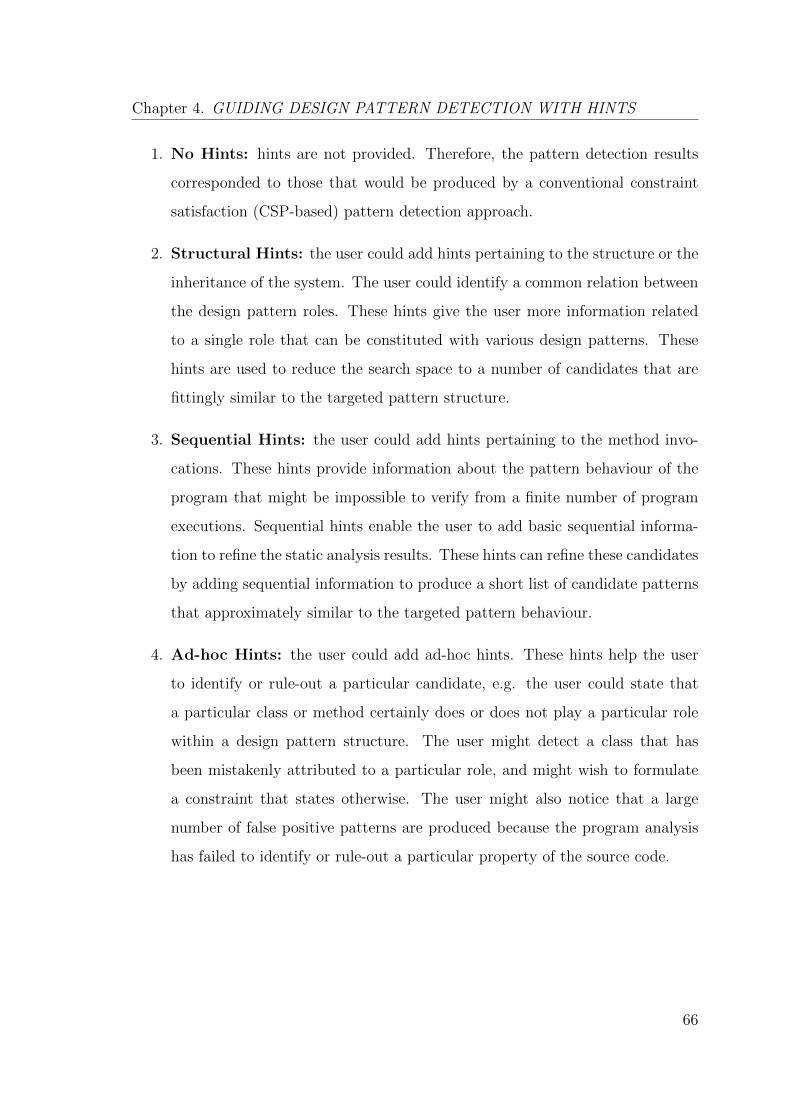
Chapter 4. GUIDING DESIGN PATTERN DETECTION WITH HINTS
1. No Hints: hints are not provided. Therefore, the pattern detection results
corresponded to those that would be produced by a conventional constraint
satisfaction (CSP-based) pattern detection approach.
2. Structural Hints: the user could add hints pertaining to the structure or the
inheritance of the system. The user could identify a common relation between
the design pattern roles. These hints give the user more information related
to a single role that can be constituted with various design patterns. These
hints are used to reduce the search space to a number of candidates that are
fittingly similar to the targeted pattern structure.
3. Sequential Hints: the user could add hints pertaining to the method invo-
cations. These hints provide information about the pattern behaviour of the
program that might be impossible to verify from a finite number of program
executions. Sequential hints enable the user to add basic sequential informa-
tion to refine the static analysis results. These hints can refine these candidates
by adding sequential information to produce a short list of candidate patterns
that approximately similar to the targeted pattern behaviour.
4. Ad-hoc Hints: the user could add ad-hoc hints. These hints help the user
to identify or rule-out a particular candidate, e.g. the user could state that
a particular class or method certainly does or does not play a particular role
within a design pattern structure. The user might detect a class that has
been mistakenly attributed to a particular role, and might wish to formulate
a constraint that states otherwise. The user might also notice that a large
number of false positive patterns are produced because the program analysis
has failed to identify or rule-out a particular property of the source code.
66

Chapter 4. GUIDING DESIGN PATTERN DETECTION WITH HINTS
4.7 Implementation
A proof-of-concept tool was developed to demonstrate the feasibility and the validity
of the proposed approach. This tool enables the application of the proposed hint
driven pattern detection approach to Java programs. The parsing and source code
analysis is carried out by the inFamix parser1. It parses and analyses the source
code to produce a large text file in a FAMIX format [37]. This constitutes a large
text file that represents the essential information regarding the system (e.g. classes,
methods, attributes, etc.). Figure 4.14 below provides an overview of the FAMIX
file core elements.
Figure 4.14: Famix Core elements [42]
In order to feed this information into a CSP to be solved by a constraint solver,
a parser was developed to extract the relevant information from the FAMIX file
as a set of facts and constraints in order to create the corresponding static models
(architecture, and behaviour). As shown in Figure 4.15, the basic parser parses and
analyses the .MSE file. In particular, it extracts all classes, methods, attributes,
invocations, inheritance, accessor, and parameter. This parser is also used to encode
the relevant information from the static models as a set of facts and constraints with
respect to the object-oriented relationships.
1http://www.intooitus.com/products/infamix
67
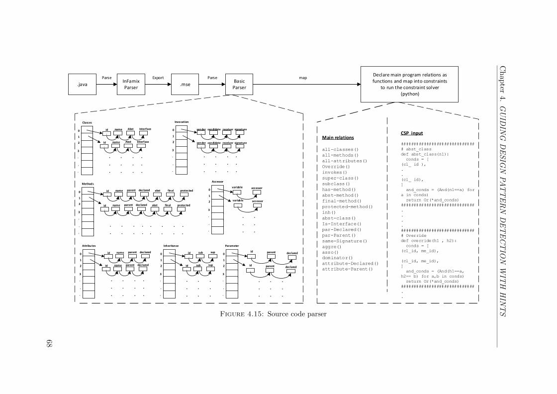
Chap
ter4.
GU
IDIN
GD
ES
IGN
PA
TT
ER
ND
ET
EC
TIO
NW
ITH
HIN
TS
.javaInFamix Parser
.mse
Parse ExportBasic
Parser
ParseDeclare main program relations as functions and map into constraints
to run the constraint solver(python)
Classes
.id name Abst Interface
id name Abst Interface
.
. . . .
. . . .
. . . .
0
1
2
3
.
.
.
Methods
.id name parent declared
. . . .
. . . .
0
1
2
3
.
.
.
Attributes
.id name parent declared
id name parent declared
.
. . . .
. . . .
. . . .
0
1
2
3
.
.
.
Invocation
.sender candidate receiver signature
. . . .
. . . .
. . . .
0
1
2
3
.
.
.
Inheritance
.id sub sup
id sub sup
.
. . .
. . .
. . .
0
1
2
3
.
.
.
abst final protected
.id name parent declared abst final protected
. . . .
. . . .
.sender candidate receiver signature
Accessor
.
variable accessor
. .
. .
. .
0
1
2
3
.
.
.
.
variable accessor
Parameter
.
id parent
. . .
. . .
. . .
0
1
2
3
.
.
.
declared
.
id parent declared
map
Main relations
all-classes()
all-methods()
all-attributes()
Override()
invokes()
super-class()
subclass()
has-method()
abst-method()
final-method()
protected-method()
inh()
abst-class()
Is-Interface()
par-Declared()
par-Parent()
same-Signature()
aggre()
asso()
dominator()
attribute-Declared()
attribute-Parent()
CSP input
#############################
# abst_class
def abst_class(n1):
conds = [
(cl_ id ),
.
.
(cl_ id),
]
and_conds = (And(n1==a) for
a in conds)
return Or(*and_conds)
#############################
.
.
.
.
#############################
# Override
def override(h1 , h2):
conds = [
(cl_id, me_id),
(cl_id, me_id),
]
and_conds = (And(h1==a,
h2== b) for a,b in conds)
return Or(*and_conds)
#############################
.
.
Figure 4.15: Source code parser
68
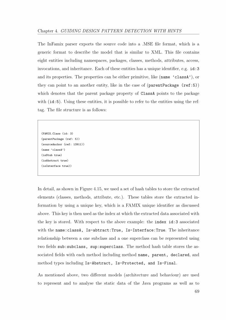
Chapter 4. GUIDING DESIGN PATTERN DETECTION WITH HINTS
The InFamix parser exports the source code into a .MSE file format, which is a
generic format to describe the model that is similar to XML. This file contains
eight entities including namespaces, packages, classes, methods, attributes, access,
invocations, and inheritance. Each of these entities has a unique identifier, e.g. id:3
and its properties. The properties can be either primitive, like (name ’classA’), or
they can point to an another entity, like in the case of (parentPackage (ref:5))
which denotes that the parent package property of ClassA points to the package
with (id:5). Using these entities, it is possible to refer to the entities using the ref:
tag. The file structure is as follows:
(FAMIX.Class (id: 3)
(parentPackage (ref: 5))
(sourceAnchor (ref: 13911))
(name ’classA’)
(isStub true)
(isAbstract true)
(isInterface true))
In detail, as shown in Figure 4.15, we used a set of hash tables to store the extracted
elements (classes, methods, attribute, etc.). These tables store the extracted in-
formation by using a unique key, which is a FAMIX unique identifier as discussed
above. This key is then used as the index at which the extracted data associated with
the key is stored. With respect to the above example: the index id:3 associated
with the name:classA, Is-abtract:True, Is-Interface:True. The inheritance
relationship between a one subclass and a one superclass can be represented using
two fields sub:subclass, sup:superclass. The method hash table stores the as-
sociated fields with each method including method name, parent, declared, and
method types including Is-Abstract, Is-Protected, and Is-Final.
As mentioned above, two different models (architecture and behaviour) are used
to represent and to analyse the static data of the Java programs as well as to
69
Chapter 4. GUIDING DESIGN PATTERN DETECTION WITH HINTS
describe the program elements. The architecture model contains all the classes, the
methods, and the attributes. The behaviour model contains the method invocations
list. These two models are used to create the corresponding model with respect to
object-oriented relationships. In fact, the need for the object-oriented parser is due
to the missing capability of the current source code analysis tools necessary to create
an intermediate representation with respect to the object-oriented relationships.
The object-oriented relationships (i.e. the associations) are essential characteristics
that are used to describe and implement a number of design patterns [54]. Current
software modelling tools (i.e. UML tools) are able to differentiate these relations
in forward engineering. However, unfortunately, they are still incapable to detect
how these relations are implemented in the source code. Thus, we utilised the
extracted source code elements (architecture and behaviour model) to identify these
relationships as described below:
• The inheritance relationship is explicitly derived from the architecture model
where the classes and the interfaces declare the classes or the interfaces they
extend or implement. For example: in each FAMIX class contains super/sub
types relationships. Thus, we represented these two types in the inheritance
hash table as sub:subclass, sup:superclass.
• The association and the aggregation are not explicitly declared in the architec-
ture model. Thus, the behaviour model (method invocation list) was utilised
to approximately identify these relationships. For example, the association
between ClassA and ClassB defines the ability of an instance of ClassA to
invoke an instance of ClassB. On the other hand, the aggregation relationship
between ClassA and ClassB exists if ClassA (the whole) contains instances of
ClassB (the part). ClassA must define a an array field of the type of ClassB
Then, the instances of ClassA invoke the instances of ClassB.
The design patterns (meta-model) are provided as abstract descriptions as described
in Gamma et al. [54]. A set of constraints were built that show the abstract model
70
Chapter 4. GUIDING DESIGN PATTERN DETECTION WITH HINTS
for the design pattern. These constraints incorporate the classes, methods and the
relationships between classes such as inheritance, association and method delega-
tions. In particular, we subsequently developed a small design pattern repository.
To do this, we took a set of behavioural patterns from Gamma et al.’s book [54] and
encoded them using again the same syntax as was used in Section 4.4. The cho-
sen patterns were the Template Method, Observer, State/Strategy, and Command
(See Appendix B). As a constraint solver we selected the Z3 constraint solver [36].
Specifically, we used the Z3Py extension, which can directly produce solutions to
text files of the format used above.
4.8 Related Work
The process used in the proposed work to acquire a set of constraints is related to the
work by Bessiere et al. on query-driven constraint acquisition [22]. Their CONACQ
approach addresses a similar problem, in the sense that they are attempting to
reason with a constraint solver about an incomplete system of constraints, and seek
further input from a user. However, whereas they formulate specific constraints as
queries to the user, the approach used here presents the user with a full hypothesis
solution (the proposed set of design patterns), and expects them to offer further
constraints (using the hypothesised patterns as a basis).
In Machine Learning terminology, whereas they pose ‘membership-queries’ (requir-
ing a simple ‘yes’ or ‘no’ as an answer), the approach proposed here uses ‘equivalence
queries’ [12], requiring the user to provide at least one counter-example. There would
certainly be a scope for the use of membership queries in this work (i.e. do modules
x and y belong together? ). However, in the software maintenance usage scenario,
where the maintainer does not necessarily have the patience to answer what could
be thousands of questions, it seems more practical to rely on their intuition to select
those counter examples that seem most obvious.
71
Chapter 4. GUIDING DESIGN PATTERN DETECTION WITH HINTS
Within software engineering, this general approach of gradually acquiring constraints
has previously been successfully applied to the problem of software re-modularisation.
Hall et al. [67] applied the same high-level framework to acquire small facts from the
developer about which classes belong together in the same package. The relevant
findings from this work are that (at least in the context of re-modularisation) it is
possible to substantially improve the accuracy of a solution with a relatively small
amount of manual input.
4.9 Summary
This chapter proposed an approach that enables the user to feed small ‘hints’ into the
detection process. This is different to some of the existing tools that permit a limited
degree of user-interaction. The proposed approach enables the developer to be much
more expressive, whilst remaining easy to use. The approach is intended to act as
a complementary ‘layer’ to enable for additional feedbacks from the developer. The
proposed approach was founded on the observation that, in order to produce reliably
accurate results, it is necessary to actively involve the developer in the pattern
detection process. The developers must be provided with as much opportunity as
possible to feed their knowledge about the system structure, its behaviour, and
the possible implementation. To address this need, this approach has proposed
a procedure that can complement the existing constraint-based pattern detection
techniques. This procedure enables the user to supply their knowledge in the form of
‘hints’ as small facts about the source code or the pattern implementations that can
enhance the results produced by the constraint solver. An application of the users’
feedbacks within an iterative detection process was proposed in this chapter. In
this application, the user was able to gradually enhances the detection results. The
proposed approach seeks to enable the user to feed his/her knowledge interactively
into the detection process, and be able to decide, to stop the detection process, or
to iterate it further.
72

Chapter 5
EXPERIMENTS
This chapter presents experiments of the capability of the proposed approach in
integrating the user knowledge into the design pattern detection process. Section 5.1
introduces the case study research question. Section 5.2 outlines the methodology
adopted in this evaluation. Section 5.3 discusses the acquired detection results.
Section 5.4 presents the evaluation of the validity of the acquired detection results
by comparing the results. Section 5.5 discusses the reasons for the false detection
results. Section 5.6 covers the threats to validity. Finally, a summary is given in
Section 5.7.
5.1 Case Study Research Question
The approach was applied to a selection of openly available software systems. The
investigated software systems have all been used to evaluate other design pattern
detection approaches. Three selected systems were presented to a user, i.e. the
researcher. The user was asked to use our tool to identify patterns by supplying
hints in a structured iterative process. After each iteration of hints, the accuracy
was measured, and the user was given the opportunity to continue. This process
73
Chapter 5. EXPERIMENTS
was repeated over four iterations. This case study seeks to establish the impact of
the user knowledge on the design pattern detection process. The specific research
question was:
RQ 1: To what extent does the use of hints lead to an increase in the accuracy of
the design pattern detection results?
The systems selected for the evaluation process are JHotDraw [2], JUnit [3], and
QuickUML [5]. These systems were selected for the evaluation of the proposed
pattern detection approach as they are mature, openly-available frameworks, built
with design-patterns in mind, and have been used as the basis for the evaluation of
several existing design pattern detection techniques (e.g. [117], [60], [33]).
5.2 Methodology
• Hint Selection The fact that the proposed approach ultimately revolves
around the input from the developer makes it challenging to evaluate. A skilled
developer could choose a small selection of highly useful hints, which would be
much more effective than those selected by an inexperienced developer, who
might select irrelevant hints that have less of an effect. To limit such sources
of bias, the hint process was systematised as much as possible. The hint
selection process was fixed to four iterations. For each iteration, the developer
was permitted to provide only the hints corresponding to a specific type of hint
template. In the first iteration, hints are not provided. Therefore, the results
corresponded to those that would be produced by a conventional constraint
satisfaction (CSP-based) pattern detection approach. In the second iteration,
the developer could add hints pertaining to the structure or the inheritance of
the system. In the third iteration, the developer could add hints pertaining to
74
Chapter 5. EXPERIMENTS
the method invocations. Finally, in the fourth iteration the developer could
add ad-hoc hints.
• Sequence of Hints The sequence in which the hints were added in phases
was fixed, to reflect the hint templates. Hints had to be chosen according to
the methodology set out in Section 4.6.1. Firstly, as mentioned above, hints
are not provided. Then, the user starts by adding structural hints, sequen-
tial hints, and finally ad-hoc hints. The structurally matched design pattern
(candidate instances) in the source code are identified based on the results of
the structural hints phase. The main goal of the structural hints is to reduce
the search space to a number of candidates that are fittingly similar to the
targeted pattern structure. Then, by adding the sequential hints, the user can
refine these candidates by adding sequential information to produce a short
list of candidate patterns that approximately similar to the targeted pattern
behaviour. Finally, the user adds the ad-hoc hints to identify or rule-out a
particular candidate. For example: the user could state that a particular class
or method certainly does or does not play a particular role within a design
pattern structure. The user might detect a class that has been mistakenly
attributed to a particular role, and might wish to formulate a constraint that
states otherwise. The user checks whether the detected whether the pattern
candidates are actually implemented in the source code or not. This step is
performed by browsing the source code and the user might wish to carry out
a cursory dynamic analysis (e.g. with the help of a debugger).
• Evaluation To assess the accuracy of the acquired results at each stage, the
‘Role-based’ pattern evaluation approach proposed by Petterson et al. [95]
was adapted. This approach adapts the classical precision recall metric [118].
Instead of focussing purely on the exact detection of an entire pattern in-
stance, they assumed that the evaluation should be carried out in terms of
the proportion of the correctly assigned roles per pattern. This enables us to
account for the partial matches, and allows for a more granular comparison.
75
Chapter 5. EXPERIMENTS
The role-based pattern evaluation is also used in the results of the approaches
in [65], and [61]. The results were computed with respect to five well-known
behavioural design patterns [54] that are problematic for the conventional pat-
tern techniques: Template Method, State, Strategy, Observer, and Command.
The lack of standard benchmarks of design pattern instances makes the eval-
uation process challenging [95]. We manually analysed the acquired results
to assess the accuracy of the detected design pattern instances. We used the
available documentation of the systems under analysis to determine the im-
plemented patterns. However, since only the popular design patterns were
mentioned in the documentation, we manually investigated the design of the
frameworks of each system from the source code in order to identify any addi-
tional implemented patterns.
• Validity One (well-established) limitation of conducting research in design
patterns is the lack of a “golden standard” by which to evaluate the retrieved
patterns [95]. Systems are poorly documented, and often fail to fully document
their patterns. Accordingly, when it comes to evaluation, one has to inevitably
use a degree of human judgement to determine whether a particular pattern
is accurate or not. The approaches in the literature were evaluated manually
based on the evaluator judgement. However, same of the design pattern in-
stance can be considered as a true positive and considered as a false negative
by another evaluator. This invariably introduces a risk of bias. To attenuate
this risk, a two-pronged evaluation approach was followed in this case study.
On one hand, as it has already been discussed in the previous paragraph, a
manual analysis was conducted to assess the veracity of the retrieved design
patterns. On the other hand, the only available peer reviewed repository of
design patterns P-MARt [59] was used as a comparison baseline.
76
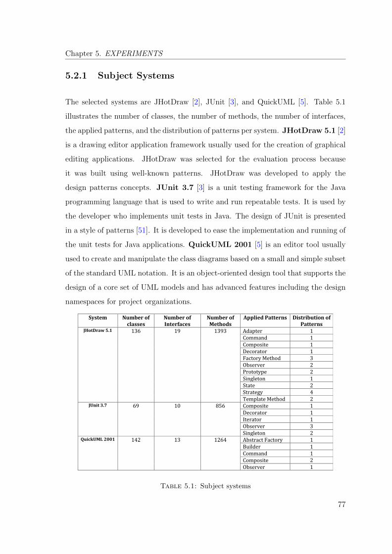
Chapter 5. EXPERIMENTS
5.2.1 Subject Systems
The selected systems are JHotDraw [2], JUnit [3], and QuickUML [5]. Table 5.1
illustrates the number of classes, the number of methods, the number of interfaces,
the applied patterns, and the distribution of patterns per system. JHotDraw 5.1 [2]
is a drawing editor application framework usually used for the creation of graphical
editing applications. JHotDraw was selected for the evaluation process because
it was built using well-known patterns. JHotDraw was developed to apply the
design patterns concepts. JUnit 3.7 [3] is a unit testing framework for the Java
programming language that is used to write and run repeatable tests. It is used by
the developer who implements unit tests in Java. The design of JUnit is presented
in a style of patterns [51]. It is developed to ease the implementation and running of
the unit tests for Java applications. QuickUML 2001 [5] is an editor tool usually
used to create and manipulate the class diagrams based on a small and simple subset
of the standard UML notation. It is an object-oriented design tool that supports the
design of a core set of UML models and has advanced features including the design
namespaces for project organizations.
System Number of classes
Number of Interfaces
Number of Methods
Applied Patterns Distribution of Patterns
JHotDraw 5.1 136 19 1393 Adapter 1 Command 1 Composite 1 Decorator 1 Factory Method 3 Observer 2 Prototype 2 Singleton 1 State 2 Strategy 4 Template Method 2
JUnit 3.7 69 10 856 Composite 1 Decorator 1 Iterator 1 Observer 3 Singleton 2
QuickUML 2001 142 13 1264 Abstract Factory 1 Builder 1 Command 1 Composite 2 Observer 1
Table 5.1: Subject systems
77
Chapter 5. EXPERIMENTS
5.3 Results & Discussion
The approach is evaluated by applying it to the detect design patterns in the above-
mentioned three open-source systems. The detected patterns instances are examined
and manually considered as true or false positives. The accuracy is calculated in
terms of precision, recall, and F-score measures. The precision measures the degree
of how much of the detected patterns are implemented (True Positives). On the
other hand, recall measures how much of the implemented patterns are detected.
F-score measures the combination of precision and recall.
Tables 5.2 and 5.3 show the evaluation results of the four phases where the accuracy
was determined by manual validation of the detected patterns. TP refers to the
number of true positives, FP refers to the number of false positives, FN refer to the
number of false negatives and P, R, and Fw refer perspectively to the precision, the
recall and the F-Score derived from these numbers, using Petterson’s metrics [95].
The tables should be read from left to right. Different types of hints were applied
in phases, which yielded the final results on the right. The results indicate that
the presentation of hints tends to increase the accuracy of the results. However,
the precision values show that any increases in the accuracy are not necessarily
monotonic, there can be substantial fluctuations.
Table 5.2 presents the results obtained from phase 1 and phase 2. In phase 1, no
hints are presented in the detection process. The result are obtained based on the
conventional constraint satisfaction pattern detection approaches. From the result
of phase 1, there is an apparent that the low rate of true positives (i.e. Template
Method in QuickUML). There is however, a high number of false positive (the case
of Command and State/Strategy in JHotDraw). In phase 2, the user adds hints
pertaining to the structure or the inheritance of the system domain.
78
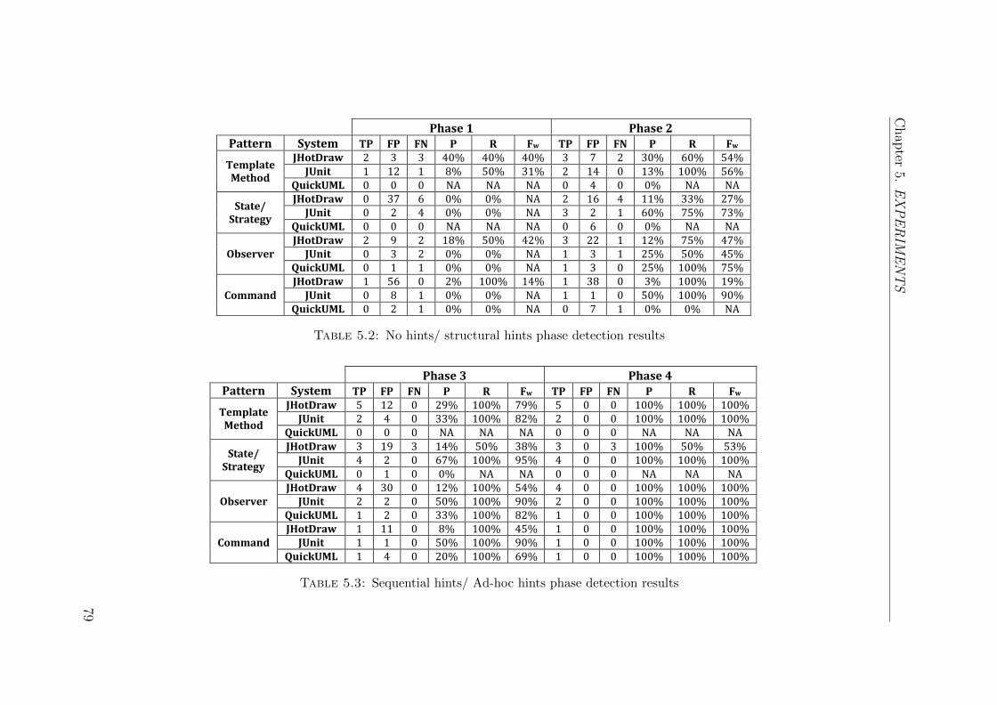
Chap
ter5.
EX
PE
RIM
EN
TS
Phase 1 Phase 2 Pattern System TP FP FN P R Fw TP FP FN P R Fw
Template Method
JHotDraw 2 3 3 40% 40% 40% 3 7 2 30% 60% 54% JUnit 1 12 1 8% 50% 31% 2 14 0 13% 100% 56%
QuickUML 0 0 0 NA NA NA 0 4 0 0% NA NA
State/ Strategy
JHotDraw 0 37 6 0% 0% NA 2 16 4 11% 33% 27% JUnit 0 2 4 0% 0% NA 3 2 1 60% 75% 73%
QuickUML 0 0 0 NA NA NA 0 6 0 0% NA NA
Observer JHotDraw 2 9 2 18% 50% 42% 3 22 1 12% 75% 47%
JUnit 0 3 2 0% 0% NA 1 3 1 25% 50% 45% QuickUML 0 1 1 0% 0% NA 1 3 0 25% 100% 75%
Command JHotDraw 1 56 0 2% 100% 14% 1 38 0 3% 100% 19%
JUnit 0 8 1 0% 0% NA 1 1 0 50% 100% 90% QuickUML 0 2 1 0% 0% NA 0 7 1 0% 0% NA
Table 5.2: No hints/ structural hints phase detection results
Phase 3 Phase 4 Pattern System TP FP FN P R Fw TP FP FN P R Fw
Template Method
JHotDraw 5 12 0 29% 100% 79% 5 0 0 100% 100% 100% JUnit 2 4 0 33% 100% 82% 2 0 0 100% 100% 100%
QuickUML 0 0 0 NA NA NA 0 0 0 NA NA NA
State/ Strategy
JHotDraw 3 19 3 14% 50% 38% 3 0 3 100% 50% 53% JUnit 4 2 0 67% 100% 95% 4 0 0 100% 100% 100%
QuickUML 0 1 0 0% NA NA 0 0 0 NA NA NA
Observer JHotDraw 4 30 0 12% 100% 54% 4 0 0 100% 100% 100%
JUnit 2 2 0 50% 100% 90% 2 0 0 100% 100% 100% QuickUML 1 2 0 33% 100% 82% 1 0 0 100% 100% 100%
Command JHotDraw 1 11 0 8% 100% 45% 1 0 0 100% 100% 100%
JUnit 1 1 0 50% 100% 90% 1 0 0 100% 100% 100% QuickUML 1 4 0 20% 100% 69% 1 0 0 100% 100% 100%
Table 5.3: Sequential hints/ Ad-hoc hints phase detection results
79
Chapter 5. EXPERIMENTS
Table 5.3 presents the results obtained from phase 3 and 4. In phase 3, the user
could add hints pertaining the method invocations. The results from this phase
show an increase of true positive values comparing to the precision values in phase
2 (i.e. State/strategy in JUnit). In addition, the results of phase 3 show a decrease
of false positive (i.e. Template method in JHotDraw). Finally, in phase 4, the user
could add ad-hoc hints. These hints depend on the user level of knowledge of the
pattern and the domain.
The precision and the recall values in these two tables can be compared. Precision
values show that any increases in the accuracy are not monotonic. For example, the
precision values of the Template method in JHotDraw are 40 % in phase 1, 30 % in
phase 2, 29 % in phase 3, and 100 % in phase 4. Recall values show any increases in
the accuracy is monotonic. For example, the recall values of the Observer pattern in
JHotDraw are 50 % in phase 1, 75 % in phase 2, and 100 % in phase 3 and 4. The
substantial fluctuations in precision values between phase 1 and 2 due to breaking
of the strict detection rules in phase 2 implies detection more patterns candidates.
These candidates can either increase the true positive or increase the false positive,
but, they will definitely decrease the false negatives. Consequently, increasing or
decreasing the true positives and false positives causes the fluctuations in precision
values. However, decreasing the false negatives causes an increase of recall values in
a monotonic manner.
Hints do not only rule out false positives (thus increasing precision), but can also
rule in false negatives. They add information about the system that may have been
omitted by the preliminary program analysis and, therefore, enable the constraint
solver to highlight the presence of additional design patterns. This can lead to a
decrease in the precision but a corresponding increase in recall. In one case the use
of hints was detrimental to accuracy. For the State/Strategy pattern in QuickUML,
the addition of hints in phases 2 and 3 only led to the detection of false positives.
Also, looking at the Observer pattern for JHotDraw, the hints added in phase 1
added 13 false positives, whilst only adding a single true positive.
80
Chapter 5. EXPERIMENTS
At first glance, the jumps to 100% precision and recall for the ad-hoc selection of
hints might appear suspicious. For the Command pattern in JHotDraw for exam-
ple, the combination of structural and sequential hints only achieves 8% precision,
whereas the inclusion of a selection of ad-hoc hints suddenly increases precision to
100% without compromising recall. First of all, it is important to bear in mind
that the ultimate number of true positives patterns is very low (a maximum of 5
occurrences). Secondly, the reason for low precision is always due to a large number
of false positives (e.g. 38 false positives for the Command pattern). This highlights
a particular strength of the use of hints, it is often trivial to rule out a large number
of false positives with a single, well-placed hint (e.g. ‘Class X is not a Command’).
This ultimately explains the large leaps in precision at the end; it is because the
developer inspects each pattern, and rules out the unlikely roles with a single hint.
5.4 Evaluation Against P-MARt Repository
As discussed earlier in Section 5.3, the lack of standard benchmarks makes the eval-
uation and the validation a difficult task. The approaches in the literature were
evaluated manually based on the evaluator judgement. However, same of the design
pattern instance can be considered as a true positive and considered as a false nega-
tive by another evaluator. Consequently, the only peer reviewed patterns repository
is used as a comparison baseline. To attenuate the risk of the acquired results being
biased, and to asses the validity of the proposed approach, we decided to re-run
our experiments using the P-MARt repository [59]. Table 5.4 shows the comparison
based on P-MARt, it shows the number of the pattern instances specified by P-MARt
repository, in addition to the number pattern instances detected by our approach.
This table also shows the number of shared instances with P-MARt repository.
81
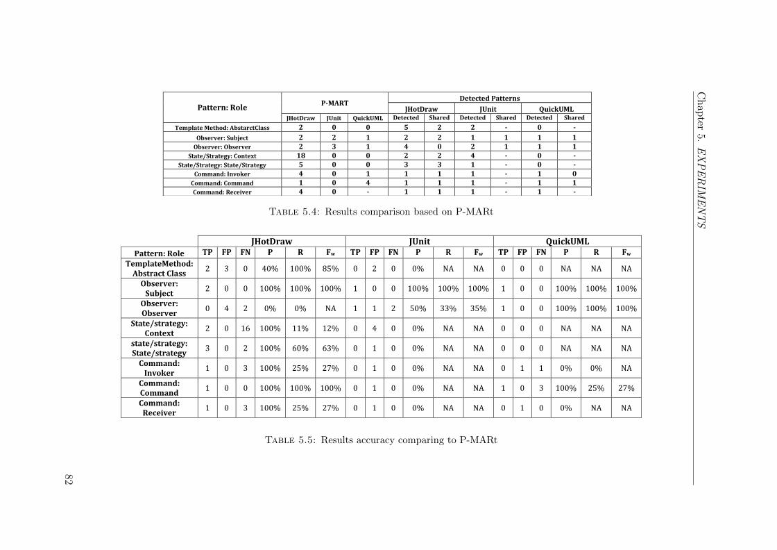
Chap
ter5.
EX
PE
RIM
EN
TS
Pattern: Role P-MART
Detected Patterns
JHotDraw JUnit QuickUML JHotDraw JUnit QuickUML Detected Shared Detected Shared Detected Shared
Template Method: AbstarctClass 2 0 0 5 2 2 - 0 -
Observer: Subject 2 2 1 2 2 1 1 1 1
Observer: Observer 2 3 1 4 0 2 1 1 1
State/Strategy: Context 18 0 0 2 2 4 - 0 -
State/Strategy: State/Strategy 5 0 0 3 3 1 - 0 -
Command: Invoker 4 0 1 1 1 1 - 1 0
Command: Command 1 0 4 1 1 1 - 1 1
Command: Receiver 4 0 - 1 1 1 - 1 -
Table 5.4: Results comparison based on P-MARt
JHotDraw JUnit QuickUML
Pattern: Role TP FP FN P R Fw TP FP FN P R Fw TP FP FN P R Fw
TemplateMethod: Abstract Class
2 3 0 40% 100% 85% 0 2 0 0% NA NA 0 0 0 NA NA NA
Observer: Subject
2 0 0 100% 100% 100% 1 0 0 100% 100% 100% 1 0 0 100% 100% 100%
Observer: Observer
0 4 2 0% 0% NA 1 1 2 50% 33% 35% 1 0 0 100% 100% 100%
State/strategy: Context
2 0 16 100% 11% 12% 0 4 0 0% NA NA 0 0 0 NA NA NA
state/strategy: State/strategy
3 0 2 100% 60% 63% 0 1 0 0% NA NA 0 0 0 NA NA NA
Command: Invoker
1 0 3 100% 25% 27% 0 1 0 0% NA NA 0 1 1 0% 0% NA
Command: Command
1 0 0 100% 100% 100% 0 1 0 0% NA NA 1 0 3 100% 25% 27%
Command: Receiver
1 0 3 100% 25% 27% 0 1 0 0% NA NA 0 1 0 0% NA NA
Table 5.5: Results accuracy comparing to P-MARt
82
Chapter 5. EXPERIMENTS
Table 5.4 illustrates the key roles playing as reported in the P-MARt repository.
This table compares our tools against the P-MARt repository based on how many
instances we share with P-MARt, this can represent a useful indication to assess the
validity of the obtained results. Table 5.4 also shows the obtained results in the three
systems. It can be seen that in JHotDraw, for the TemplateMethod:AbstractClass
role we detected five roles, and we shared the two roles as reported. The approach de-
tected Observer:Subject role as reported by P-MARt. For the Observer:Observer
we detected four instances but we did not share any of the reported roles.
Concerning the State/Strategy:Context the approach shared two instances and
missed sixteen reported roles. On the other hand, for State/Strategy:Context we
shared three roles out of five as reported. For the three key role playing in Command
pattern, we shred the exact instance of Command:Command role, one out four for both
Command:Invoker and Command:Receiver. In JUnit, the reported key role playing
in P-MARt are only two Observer:Subject and three Observer:Observer. The
approach shared one instance of both roles. Finally, in QuickUML the reported roles
are one Observer:Subject and one Observer:Observer, we shared the exact roles
as reported. On the other hand, three of the Command:Command roles in QuickUML
were missed, and we only shared one instance. Overall, our approach is a viable for
sharing key role playing classes as reported by P-MARt.
Table 5.5 shows the numbers of true positives TP, false positives FP, false negatives
FN, the precision P, the recall R, and the F-score Fw values for each design pattern
instance/role compared to the roles reported in the P-MARt repository. Besides,
Tables 5.6, 5.7, and 5.8 show the actual roles detected in the three selected systems,
along with the actual roles specified in P-MARt repository. As can be seen from
these tables, there is a significant overlap between the patterns detected by our
approach and those reported in the P-MARt repository. Although the performance
of the detection results is highly accurate for QuickUML and JUnit, several roles
remain undetected by the approach for JHotDraw. This is especially the case for
the State/Strategy pattern. The inaccuracy comes down to an overly strict set of
83
Chapter 5. EXPERIMENTS
constraints that were used to define the base-pattern, and the subsequent failure of
hints to loosen this definition to a sufficient degree.
In JHotDraw, the results show that we are able to detect Template method pattern
instances with good recall whilst having some false positives that affect the precision
value. In particular, three of the detected instances of AbstractClass role were
identified as false positives which affect the precision (40%). However, a subsequence
manual analysis of the source code and the documentation, the analysis shows that
these instances were in fact true positive instances. This is due to the fact that
the Template pattern can be implemented with a variety of code implementation
styles. For example, class LineConnection in CH.ifa.figures package plays the
AbstractClass role. This is also the case for class LineDecoration in the same
package.
The proposed approach works well in detecting the Observer:Subject role. The
results show 100% precision and recall since the approach was capable to detect all
the Observer:Subject roles specified in P-MARt. However, with the Observer:
Observer role the approach was unable to match any reported role in the P-MARt
repository. The results indicate that the four detected roles were considered as false
positive which affects the precision. In addition, the approach missed two roles as
reported in P-MARt repository, which are considered as false negatives and, hence,
affect the recall of the detection of the Observer:Observer role.
Regarding the detection of the State/Strategy pattern in JHotDraw, there are too
many missing role instances (16 instances) for the State/Strategy:Context role,
which negatively affect the recall (11%). It is possible that these results are due
to the highly dynamic behaviour of the State/Strategy pattern. In particular, the
relation between the pattern roles depends mainly on the value of the field at the
run time. Thus, the variations of the method delegation implementations between
the State/Strategy:Context and State/Strategy:State/Strategy seems to be
the main reason behind the undiscovered context role.
84
Chapter 5. EXPERIMENTS
Concerning the Command pattern, the approach detected the Command:Command
role with 100% precision and recall (CH.if.draw.util.Command). However, there
are some missing Command:Invoker and Command:Receiver roles which affect the
recall rate (25%). The reason is due to the multiple inheritance constraints; some
roles do not belong to any inheritance hierarchy with the Command:Command role. A
possible explanation for this might be that with adding the constraints at different
level of inheritance hierarchy, we can detect these roles. Whereas the detection of
the common interface ( a class named CH.if.draw.util.Command) can help to iden-
tify the other Command:Invoker and Command:Receiver roles, where all command
inherits from the common abstract interface.
In JUnit, the proposed approach was able to detect the Observer:Subject role with
a 100% precision and a 50% recall. This is because the approach missed one of the
reported roles. The P-MARt reported only two instances of the observer:Subject
role and three instances of the Observer:Observer role. However, with Observer:
Observer role, the proposed approach detected two instances, one was considered
as a true positive (junit.framework.TestListener) and the other was considered
as a false positive (junit.framework.Test), which affects the acquired precision by
50%. The proposed approach also missed two of the reported roles, which affect the
recall 33% (java.awt.event.MouseListener and java.awt.event.KeyListener).
In QuickUML, the results show 100% in both, the precision and the recall of the
Observer:Subject and the Observer:Observer roles. However, with the Com-
mand pattern, the proposed approach detected one instance of the Command:Invoker
role that was considered false positive which affect the precision. In addition, our
approach missed one instance reported in P-MARt (false negatives) which affect
the recall. For the Command:Command role, our approach detected one instance
(uml.ui.ExportAction) out of the four instances reported in P-MARt. This gives
100% precision but with low recall (25%) since the proposed approach has missed
three reported roles.
85
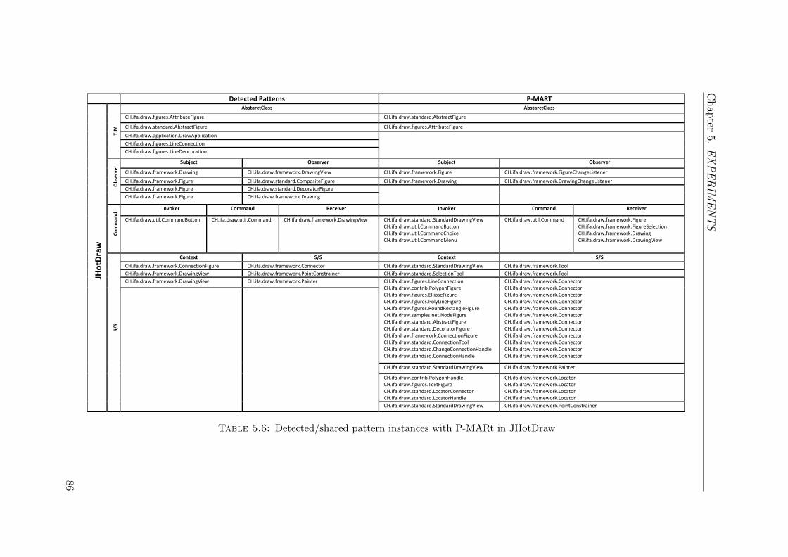
Chap
ter5.
EX
PE
RIM
EN
TS
Detected Patterns P-MART JH
otD
raw
T.M
AbstarctClass AbstarctClass
CH.ifa.draw.figures.AttributeFigure CH.ifa.draw.standard.AbstractFigure
CH.ifa.draw.standard.AbstractFigure CH.ifa.draw.figures.AttributeFigure
CH.ifa.draw.application.DrawApplication
CH.ifa.draw.figures.LineConnection
CH.ifa.draw.figures.LineDeocoration
Ob
serv
er Subject Observer Subject Observer
CH.ifa.draw.framework.Drawing CH.ifa.draw.framework.DrawingView CH.ifa.draw.framework.Figure CH.ifa.draw.framework.FigureChangeListener
CH.ifa.draw.framework.Figure CH.ifa.draw.standard.CompositeFigure CH.ifa.draw.framework.Drawing CH.ifa.draw.framework.DrawingChangeListener
CH.ifa.draw.framework.Figure CH.ifa.draw.standard.DecoratorFigure
CH.ifa.draw.framework.Figure CH.ifa.draw.framework.Drawing
Co
mm
and
Invoker Command Receiver Invoker Command Receiver
CH.ifa.draw.util.CommandButton
CH.ifa.draw.util.Command
CH.ifa.draw.framework.DrawingView CH.ifa.draw.standard.StandardDrawingView CH.ifa.draw.util.CommandButton CH.ifa.draw.util.CommandChoice CH.ifa.draw.util.CommandMenu
CH.ifa.draw.util.Command
CH.ifa.draw.framework.Figure CH.ifa.draw.framework.FigureSelection CH.ifa.draw.framework.Drawing CH.ifa.draw.framework.DrawingView
S/S
Context S/S Context S/S
CH.ifa.draw.framework.ConnectionFigure CH.ifa.draw.framework.Connector CH.ifa.draw.standard.StandardDrawingView CH.ifa.draw.framework.Tool
CH.ifa.draw.framework.DrawingView CH.ifa.draw.framework.PointConstrainer CH.ifa.draw.standard.SelectionTool CH.ifa.draw.framework.Tool
CH.ifa.draw.framework.DrawingView CH.ifa.draw.framework.Painter CH.ifa.draw.figures.LineConnection CH.ifa.draw.contrib.PolygonFigure CH.ifa.draw.figures.EllipseFigure CH.ifa.draw.figures.PolyLineFigure CH.ifa.draw.figures.RoundRectangleFigure CH.ifa.draw.samples.net.NodeFigure CH.ifa.draw.standard.AbstractFigure CH.ifa.draw.standard.DecoratorFigure CH.ifa.draw.framework.ConnectionFigure CH.ifa.draw.standard.ConnectionTool CH.ifa.draw.standard.ChangeConnectionHandle CH.ifa.draw.standard.ConnectionHandle
CH.ifa.draw.framework.Connector CH.ifa.draw.framework.Connector CH.ifa.draw.framework.Connector CH.ifa.draw.framework.Connector CH.ifa.draw.framework.Connector CH.ifa.draw.framework.Connector CH.ifa.draw.framework.Connector CH.ifa.draw.framework.Connector CH.ifa.draw.framework.Connector CH.ifa.draw.framework.Connector CH.ifa.draw.framework.Connector CH.ifa.draw.framework.Connector
CH.ifa.draw.standard.StandardDrawingView CH.ifa.draw.framework.Painter
CH.ifa.draw.contrib.PolygonHandle CH.ifa.draw.figures.TextFigure CH.ifa.draw.standard.LocatorConnector CH.ifa.draw.standard.LocatorHandle
CH.ifa.draw.framework.Locator CH.ifa.draw.framework.Locator CH.ifa.draw.framework.Locator CH.ifa.draw.framework.Locator
CH.ifa.draw.standard.StandardDrawingView CH.ifa.draw.framework.PointConstrainer
Table 5.6: Detected/shared pattern instances with P-MARt in JHotDraw
86
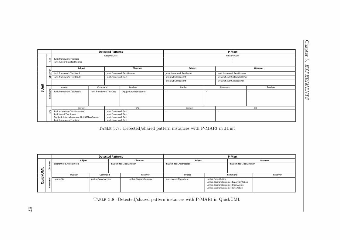
Chap
ter5.
EX
PE
RIM
EN
TS
Detected Patterns P-Mart
JUn
it
T.M
AbstarctClass AbstarctClass
Junit.framework.TestCase junit.runner.BaseTestRunner
- -
Ob
serv
er Subject Observer Subject Observer
junit.framework.TestResult junit.framework.TestListener junit.framework.TestResult junit.framework.TestListener
junit.framework.TestResult junit.framework.Test java.awt.Component java.awt.event.MouseListener
java.awt.Component java.awt.event.KeyListener
Co
mm
and
Invoker Command Receiver Invoker Command Receiver
Junit.framework.TestResult Junit.framework.TestCase Org.junit.runner.Request - - -
S/S
Context S/S Context S/S
Junit.extensions.TestDecorator Junit.textui.TestRunner Org.junit.internal.runners.JUnit38ClassRunner Junit.framework.TestSuite
junit.framework.Test junit.framework.Test junit.framework.Test junit.framework.Test
- -
Table 5.7: Detected/shared pattern instances with P-MARt in JUnit
Detected Patterns P-Mart
Qu
ickU
ML
Ob
serv
er Subject Observer Subject Observer
diagram.tool.AbstractTool diagram.tool.ToolListener diagram.tool.AbstractTool diagram.tool.ToolListener
Co
mm
and
Invoker Command Receiver Invoker Command Receiver
java.io.File uml.ui.ExportAction
uml.ui.DiagramContainer javax.swing.JMenuItem
uml.ui.ExportAction uml.ui.DiagramContainer.ExportGIFAction uml.ui.DiagramContainer.OpenAction uml.ui.DiagramContainer.SaveAction
-
Table 5.8: Detected/shared pattern instances with P-MARt in QuickUML
87
Chapter 5. EXPERIMENTS
5.5 Reasons for False Detection
Overall, it can be seen that the overlap between the acquired results and the P-
MARt repository is encouraging. The results indicate that the use of hints in an
iterative manner shows a significant improvement in the detection results, not only
reducing false positive but also detecting more patterns, which reduces false nega-
tives. However, there are several possible explanations for false positives and false
negatives detection results, the major reasons are as follows:
5.5.1 Design Pattern Variants
Design pattern variants are one of the main problems that affect the accuracy of
the design pattern detection approaches [102]. Some patterns can be implemented
in a variety of different ways, and it is not possible to define all the patterns im-
plementation variants. The proposed approach provided a flexibility in customising
(breaking) the detection constraints by the user. However, there are still some im-
plementation variants that produce some false negatives. A future research should
therefore concentrate on investigating possible variants of the design patterns and on
creating a catalogue of all common pattern implementations with proper hints types.
There will, of course, never be a complete catalogue, but our approach provides a
facility of easy customization of the detection constraints by the user.
5.5.2 Dynamic Data Flow
The lack of the dynamic (runtime) data flow analysis affects the detection of the
patterns that rely on method delegations at runtime. Dynamic data flow analysis
is the analysis of the data sequence of actions during the program execution [26].
Method delegation is the concept of passing tasks between methods during the pro-
gram execution [108]. For example: a given method invokes the other methods
88
Chapter 5. EXPERIMENTS
at the program runtime. Method delegation is the most important property used
to implement a number of design patterns [54]. In particular, in object-oriented
programming, delegation is used to describe the case where one object allocates a
task to another object (the delegate). However, the identification of the method
delegation information is challenging. The reason due the fact that the delegation
can be implemented by different ways in different source systems [103]. Therefore,
providing hints at the method delegation needs additional analysis at the program
execution time. These hints rely on the dynamic analysis of the execution traces
captured at program runtime. Further work is needed focusing on providing hints
based on the method delegation information. This would be interesting since these
hints will establish a greater degree of accuracy to handle the challenge of detecting
patterns that rely on the method delegation information.
5.5.3 Parser Capabilities
Another possible explanation is the source code analysis and parser limitations. The
parser limitations rise due to missing capability of the current source code analysis
tools to create an intermediate representation with respect to the object-oriented
relationships. The object-oriented relationships (i.e the associations) are essential
characteristics that are used to describe and implement a number of design patterns
[54]. Current software modelling tools (i.e UML tools) are able to differentiate these
relations in forward engineering. However, unfortunately, they are still incapable to
detect how these relations are implemented in the source code. Thus, we utilised
the extracted source code elements (architecture and behaviour model) to identify
these relationships. A parser was developed to extract the relevant information from
the source code to create the corresponding models (architecture, and behaviour).
It was also used to create the relevant information as a set of facts and constraints
with respect to the object-oriented relationships. For example, the inheritance re-
lationship is explicitly derived from the architecture model where the classes and
89
Chapter 5. EXPERIMENTS
the interfaces declare the classes or the interfaces they extend or implement. On
the other hand, the association relationships are not explicitly declared in the archi-
tecture model. Thus, the behaviour model (method invocation list) was utilised to
identify approximately these relationships.
The association relationships are difficult to identify because their lack of precise
definitions [57]. They require the dynamic information as they do not appear in
the source code explicitly. However, the accuracy for identifying these relationships
may differ depending on the program execution. The identification of the association
relationships is subject to the common limitations of dynamic data flow analyses.
Therefore, there are, of course, an entire common program features that the source
code parser is unlikely ever to be able to detect. Thus, some roles of design patterns
could be missed in the recovered instances. A robust and flexible parser is an
important issue that helps in identifying the main feature of the patterns for a more
precise detection. The limitation of the source code parser requires additional effort.
The development of a robust parser requires an intensive effort and time. In the
future, it is recommended to enhance the source code parser with more capabilities
for the detection of the object-oriented relationships.
5.6 Threats to validity
5.6.1 Internal Validity
This validity threats concerns with the relation between the observed improvements
in the detection results and the selection of hints; The hints used for the evaluation
were selected by the principal author. The selection of hints is critical to the efficacy
of the approach. The fact that the hints were selected by a single author does raise
the possibility that the selection was biased by the author’s extensive familiarity with
the proposed technique. The risk of bias was attenuated by the fact that the selection
90
Chapter 5. EXPERIMENTS
of hints was systematised by using a set of hint-templates. Furthermore, Chapter 5
presents a controlled user study that involves a broader range of participants. This
study more carefully explores the selection of hints with a view to determining which
hints are especially useful.
5.6.2 External Validity
The subject systems are not representative of the broad family of software systems.
Two of them are GUI-driven diagramming software systems. And there are only
three systems in total. This makes it difficult to generalise from these results to
broader classes and sized systems. This leads to the threat that the conclusions
drawn from the acquired validation results do not generalise to a sufficiently broad
range of systems. Further evaluation with different systems may reduce this threat.
Furthermore, a user study in Chapter 6 may give an insight onto how the users are
able to determine hints that can feed the design pattern detection process. The fact
that the investigated systems are relatively diverse in purpose does attenuate this
threat to a certain extent. However, it is part of the future work to further evaluate
the proposed approach using wider range of systems.
5.6.3 Conclusion validity
As discussed before, the hints were fixed into four iterations, and the evaluation
was conducted by the researcher. However, with a real developer this might cause
a risk if the users who provided the hints were not experts in the domain system
or in the design patterns. This will affect the result collected based on the user
intervention. In fact, the user error has an impact on all systems that require a user
intervention [70]. In this case, the consequences of the user errors lead to incorrect
detection results. Users with minimum programming skills might find it difficult to
understand the design pattern through the code. This risk was attenuated by the
91
Chapter 5. EXPERIMENTS
hints templates that help in providing a good deal of information to the users with
minimum skills by providing predefined hints to ease the supplement. However, it is
part of the future work to rerun the experimentation with expert developers. There
would be a useful utility of the approach if the users were actually experts.
5.7 Summary
Three open-source systems were selected for the evaluation process. These systems
selected for this purpose as they are openly-available frameworks, built with design-
patterns in mind, and have been used as the basis for the evaluation of several
existing design-pattern detection techniques. During the evaluation process, the
accuracy was measured, and the user was given the opportunity to continue the
detection process. The hint selection process was systematised as much as possible
to limit the potential of bias in the results. The detection process was limited
to four iterations, where for each iteration the developer was only permitted to
provide hints corresponding to a specific type of hint template. The detection results
indicated that the use of hints substantially increases the accuracy of the design
pattern detection process. Furthermore, the overlap between the acquired results
and the P-MARt [59] repository is encouraging.
92
Chapter 6
PATTERN DETECTION AND
USER KNOWLEDGE
The use of empirical studies in software engineering has matured considerably in the
last two decades [94]. Software engineering researchers are becoming more familiar
with the concept of stating their scientific hypothesises [79]. Empirical studies in
software engineering are usually conducted to gather and utilise evidence to advance
software engineering methods, processes, techniques, and tools [18]. There are three
major strategies for performing empirical studies including; surveys, case studies,
and experiments [105]. The selection of an appropriate strategy depends mainly on
the purpose of the study, and on the conditions of the investigation.
The user survey strategy was adopted in the present study. If the user survey is
conducted properly, it allows the researcher to generalise about the beliefs and the
opinions of many people by studying a subset of them [73]. The user survey is
a method for collecting information from or about people to describe, compare or
explain their knowledge, attitudes and behaviour [48]. It helps to gain an insight
into the people minds or the problems within a specific study.
93
Chapter 6. USER STUDY: PATTERN DETECTION AND USER KNOWLEDGE
This chapter presents a user study that involves a broader range of expert users
of design patterns. Section 6.1 introduces the aims and objectives, and presents
the research question and hypothesis of this study. The overall methodology and
study protocol are discussed in Section 6.3. The data analysis results are presented
in Section 6.4. The study threats to validity is discussed in Section 6.5. Finally,
Section 6.6 presents a summery of this chapter.
6.1 Aims and Objectives
The research findings in Chapter 5 indicate that the expert user can gradually en-
hance the detection results with the use of hints. Therefore, for the purpose of
highlighting this knowledge, a more user-oriented study was conducted to consider
the impact of user knowledge on the detection process. This study investigated
whether it is realistic that the expert user can identify useful hints to the design
pattern detection process. This involved a broad range of participants, and care-
fully explored the selection of hints, with clear view to determining which hints are
especially useful for the related patterns and contexts.
There is no widely accepted framework to study the combination of automatic detec-
tion tools with user inputs. Tonella et al. [115] proposed some criteria for classifying
the empirical studies in reverse engineering. Thus, under those circumstances they
classified the study of the user guidance in terms of whether the tool requires from
the user, or what guidance is required from the user. This criteria benefit this re-
search study to gauge factors sue has the amount of user input required, and the
nature of that input. Therefore, an empirical study was conducted to collect, pro-
cess, and analyse the users’ responses. The data was collected from several expert
users in design patterns (researchers, developers, maintainers, etc.).
94
Chapter 6. USER STUDY: PATTERN DETECTION AND USER KNOWLEDGE
6.2 Research Question & Hypotheses
In this study, the opinions extracted from different expert users of design patterns
are considered and analysed by conducting a survey. This will explore the selection
of hints with a view to determining which hints are especially useful. This survey
will investigate the impact of user knowledge in the detection process. Furthermore,
the survey will evaluate the users’ level of experience and its effect on the amount
of the provided knowledge. The overall research question was:
RQ 2. Are users certainly aware of which hints that do and do not constitute a
useful feedback for a given type of pattern?
The results of this survey are intended to evaluate the claim that users are likely to
identify useful hints that can help in the detection of pattern instances in the source
code. The study in this chapter will verify the following research hypothesis:
H1: : Users can identify useful hints that feed the design pattern detection process.
Participants who are considered as experienced users are able to think effectively
in regards to design patterns. Understanding the structure of the design pattern is
important because it provides insights into the intent of such a pattern and into its
implementation. The results analysis will show how the identification of useful hints
can differentiate expert users from novice users. Participants’ knowledge affects
how they understand the design pattern structure and implementations and how
they identify the useful feedback in the selected scenarios. This, in turn, reflects
their programming experience, and their abilities to solve design problems.
We conjecture that participants who are considered as experienced users can iden-
tifying more useful hints comparing to novice users. Therefore, for the purpose of
extensively investigating the difference between the participants’ level of experience
and its effect on the identification of hints, the following hypothesis will be tested:
95
Chapter 6. USER STUDY: PATTERN DETECTION AND USER KNOWLEDGE
H2: Respondents perform differently according to their experience.
We expect the novice users to be more familiar with structural and creational pat-
terns than expert users. The reasons behind these familiarity comes from our un-
derstanding and experience with design patterns. These two categories rely on the
inter-classes relationships which can be recognised statically. This indicates that
novice users are familiar with the structural hints, because these hints characterise
some structural information that can feed in detecting the structural and the cre-
ational patters. On the other side, behavioural patterns are problematic patterns
because these patterns rely on the runtime data and the implementation of these
patterns may vary. Therefore, identifying the implementation variants for the be-
havioural patterns requires a high level of experience and programming skills. Expe-
rienced user can identify these variants comparing to novice users based on his/her
knowledge. This indicates that expert users are more familiar with sequential hints.
6.3 Methodology
A user-oriented study was performed to investigate the impact of user knowledge
on the detection process. This involved surveying a broad range of participants,
and carefully explored the selection of hints, with a clear view of determining which
hints are especially useful for the related patterns and contexts. The survey starts by
presenting each user with a particular pattern detection scenario from the three open
source systems that were used in RQ1 (JHotDraw [2], JUnit [3], and QuickUML [5]),
and then asking them to rate the usefulness of a selection of hints to support the
detection of a given pattern instance in the source code.
This study of the design patterns aim to investigate the experiences of professionals
in design patterns. In order to perform a more comprehensive investigation of the
design patterns and to fulfil the goal of this study, only expert users in design patterns
96
Chapter 6. USER STUDY: PATTERN DETECTION AND USER KNOWLEDGE
and domain were identified as the targeted sampling frame. Their responses formed
the data for the analysis process. This sample provides a further insight and helps
in electing useful knowledge that is drawn upon the expert experiences.
Each participant was asked to decide on the hints that were considered as useful or
not useful for a given design pattern in the selected scenarios. For each scenario,
half of the hints are known to be useful (positive) and the other half are known
to be useless (negative). This categorisation was not disclosed to the users. The
participants were asked to evaluate the hints using the ordinal Likert scale [85]: Very
Negative (VN), Negative (N), Not Significant (NU), Positive (P), and Very Positive
(VP). The process of performing the survey includes three main stage [125]; Survey
Design, Survey Operation, and Data Analysis. Furthermore, Kitchenham et al. [79]
proposed guidelines for conducting empirical research in software engineering that
were followed in this study.
6.3.1 Survey Design
This study is surveying the experience of expert users in GoF design patterns [54]
in order to capture whether a user can provide useful knowledge to support the
automated detection of pattern instances in the source code. A set of experts were
identified as the sampling frame of the survey, and their responses formed the appro-
priate data for the analysis process. This section describes three important parts of
survey design process including the population & sampling, the questionnaire form
& protocol, and the pilot test.
6.3.1.1 Population and Sampling
Designing surveys requires careful selection of participants. The target population
is the group or individuals to whom the survey applies. Sampling is the process
of selecting a subset from the entire population under study. Ideally, the selected
97
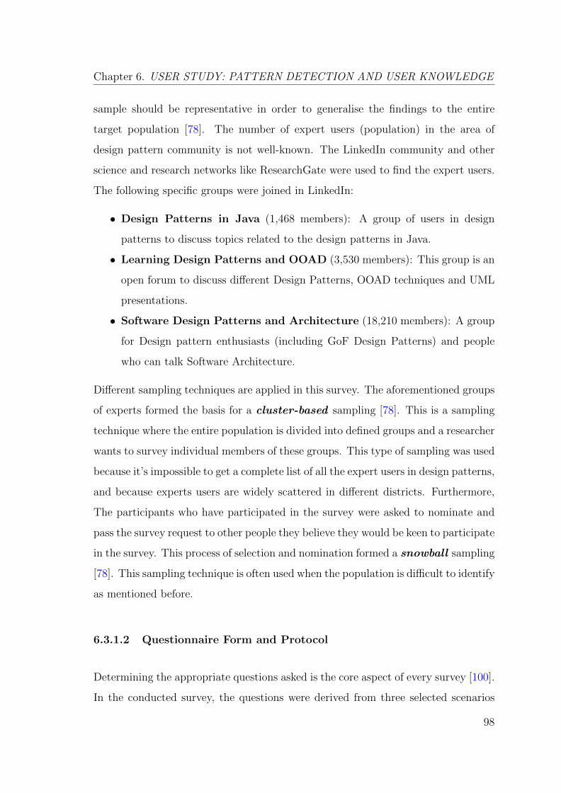
Chapter 6. USER STUDY: PATTERN DETECTION AND USER KNOWLEDGE
sample should be representative in order to generalise the findings to the entire
target population [78]. The number of expert users (population) in the area of
design pattern community is not well-known. The LinkedIn community and other
science and research networks like ResearchGate were used to find the expert users.
The following specific groups were joined in LinkedIn:
• Design Patterns in Java (1,468 members): A group of users in design
patterns to discuss topics related to the design patterns in Java.
• Learning Design Patterns and OOAD (3,530 members): This group is an
open forum to discuss different Design Patterns, OOAD techniques and UML
presentations.
• Software Design Patterns and Architecture (18,210 members): A group
for Design pattern enthusiasts (including GoF Design Patterns) and people
who can talk Software Architecture.
Different sampling techniques are applied in this survey. The aforementioned groups
of experts formed the basis for a cluster-based sampling [78]. This is a sampling
technique where the entire population is divided into defined groups and a researcher
wants to survey individual members of these groups. This type of sampling was used
because it’s impossible to get a complete list of all the expert users in design patterns,
and because experts users are widely scattered in different districts. Furthermore,
The participants who have participated in the survey were asked to nominate and
pass the survey request to other people they believe they would be keen to participate
in the survey. This process of selection and nomination formed a snowball sampling
[78]. This sampling technique is often used when the population is difficult to identify
as mentioned before.
6.3.1.2 Questionnaire Form and Protocol
Determining the appropriate questions asked is the core aspect of every survey [100].
In the conducted survey, the questions were derived from three selected scenarios
98
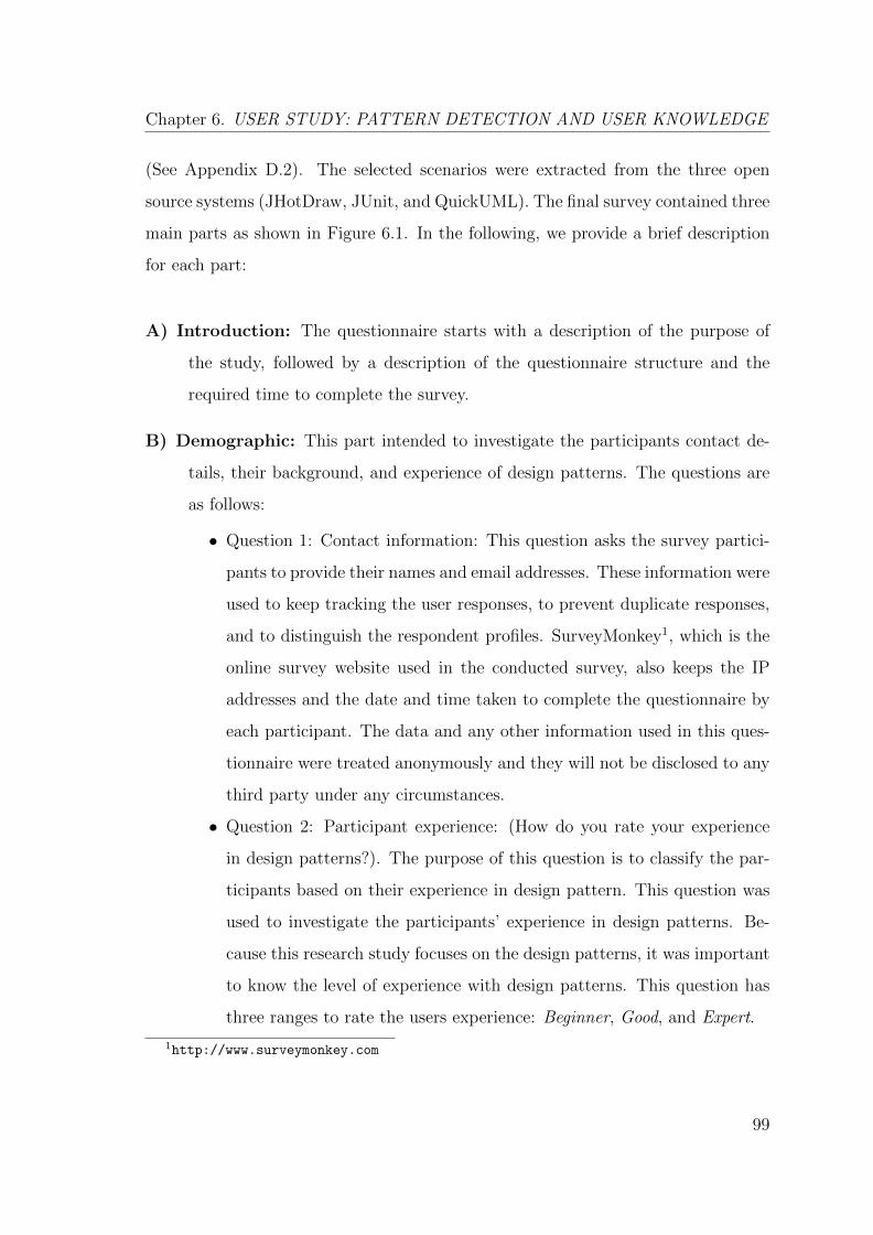
Chapter 6. USER STUDY: PATTERN DETECTION AND USER KNOWLEDGE
(See Appendix D.2). The selected scenarios were extracted from the three open
source systems (JHotDraw, JUnit, and QuickUML). The final survey contained three
main parts as shown in Figure 6.1. In the following, we provide a brief description
for each part:
A) Introduction: The questionnaire starts with a description of the purpose of
the study, followed by a description of the questionnaire structure and the
required time to complete the survey.
B) Demographic: This part intended to investigate the participants contact de-
tails, their background, and experience of design patterns. The questions are
as follows:
• Question 1: Contact information: This question asks the survey partici-
pants to provide their names and email addresses. These information were
used to keep tracking the user responses, to prevent duplicate responses,
and to distinguish the respondent profiles. SurveyMonkey1, which is the
online survey website used in the conducted survey, also keeps the IP
addresses and the date and time taken to complete the questionnaire by
each participant. The data and any other information used in this ques-
tionnaire were treated anonymously and they will not be disclosed to any
third party under any circumstances.
• Question 2: Participant experience: (How do you rate your experience
in design patterns?). The purpose of this question is to classify the par-
ticipants based on their experience in design pattern. This question was
used to investigate the participants’ experience in design patterns. Be-
cause this research study focuses on the design patterns, it was important
to know the level of experience with design patterns. This question has
three ranges to rate the users experience: Beginner, Good, and Expert.
1http://www.surveymonkey.com
99
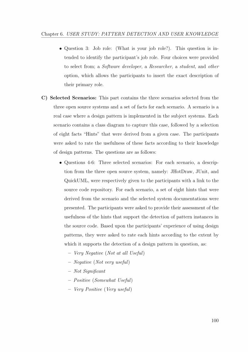
Chapter 6. USER STUDY: PATTERN DETECTION AND USER KNOWLEDGE
• Question 3: Job role: (What is your job role?). This question is in-
tended to identify the participant’s job role. Four choices were provided
to select from; a Software developer, a Researcher, a student, and other
option, which allows the participants to insert the exact description of
their primary role.
C) Selected Scenarios: This part contains the three scenarios selected from the
three open source systems and a set of facts for each scenario. A scenario is a
real case where a design pattern is implemented in the subject systems. Each
scenario contains a class diagram to capture this case, followed by a selection
of eight facts “Hints” that were derived from a given case. The participants
were asked to rate the usefulness of these facts according to their knowledge
of design patterns. The questions are as follows:
• Questions 4-6: Three selected scenarios: For each scenario, a descrip-
tion from the three open source system, namely: JHotDraw, JUnit, and
QuickUML, were respectively given to the participants with a link to the
source code repository. For each scenario, a set of eight hints that were
derived from the scenario and the selected system documentations were
presented. The participants were asked to provide their assessment of the
usefulness of the hints that support the detection of pattern instances in
the source code. Based upon the participants’ experience of using design
patterns, they were asked to rate each hints according to the extent by
which it supports the detection of a design pattern in question, as:
– Very Negative (Not at all Useful)
– Negative (Not very useful)
– Not Significant
– Positive (Somewhat Useful)
– Very Positive (Very useful)
100
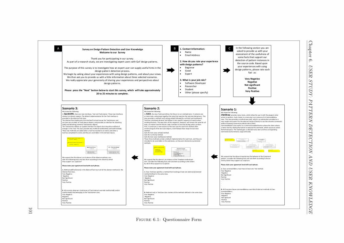
Chap
ter6.
US
ER
ST
UD
Y:
PA
TT
ER
ND
ET
EC
TIO
NA
ND
US
ER
KN
OW
LE
DG
E
1. Contact Information: Name Email Address
2. How do you rate your experience with design patterns? Beginner Good Expert
3. What is your job role? Software Developer Researcher Student Other (please specify)
Survey on Design Pattern Detection and User KnowledgeWelcome to our Survey
Thank you for participating in our survey.As part of a research study, we are investigating expert users with GoF design patterns.
The purpose of this survey is to investigate how an expert user can supply useful hints in the design pattern detection process.
We begin by asking about your experiences with using design patterns, and about your views. We then ask you to provide us with a little information about three selected scenarios .
We really appreciate your generosity of sharing your experiences and perspectives about design patterns.
Please press the ''Next" button below to start this survey, which will take approximately
20 to 25 minutes to complete.
In the following section you are asked to provide us with your
assessment of the usefulness of some facts that support our
detection of pattern instances in the source code. Based upon your experiences with using
design patterns, please rate each fact as:
Very NegativeNegative
Not significantPositive
Very Positive
Scenario 1:We know the following:
JHotDraw provides menu items, which allow the user to tell the program what
action to perform. Each choice in a menu bar is an instance of a CommandMenuclass. This class provides a method execute(), which is an abstraction provided as avery simple entry point For the external classes (Clients) to use the concrete commandswithout knowing unnecessary details about them.CommandButton class works as a command enabled button where the client selectsa menu item by clicking the button to execute the command, which causes an action-Performed event. The method gets a selected menu item and the correspondingCommand (CutCommand, copyCommand).
We suspect that the above characterises the behavior of the Commandpattern, consider the following facts and rate them according to the ex-tent by which they support our suspicion.
Please state your agreement level with each phrase.
1. Class commandMenu must have at least one ?nal method.Very Negative Negative Not SignificantPositive Very Positive...
8. All Concrete classes commandMenus override all abstract methods of class commandMenu.Very Negative Negative Not Signicant Positive Very Positive
Scenario 2:We know the following:
In JUnit, the class TestCase defines the fixture to run multiple tests. It contains one
or more tests, and groups together the tests that exercise the common behaviours. This class provides a method run() calling setUp() fo llowed by runTest() and tearDown().TestCase is declared abstract and follows a very specific sequence of events wheninvoking the tests. The execution of this sequence, however, will remain the same for alltests, no matter how the fixture code is written or how the testing code is written.First, it constructs a new instance of the test case for each test method. Afterconstructing all of the test case objects, JUnit follows these steps for each testmethod:Calls the test cases setUp() method.Calls the runTest() method.Calls the test cases tearDown() method.These three methods contain a default implementation for each test, and they areintended to be overridden in the subclasses, so they were declared as protected methods.
We suspect that the above is an instance of the Template method pat-tern. Consider the following facts and rate them according to the extentby which they support our suspicion.
Please state your agreement level with each phrase.
1. Class TestCase specifies a method that invoking at least one abstract/protectedmethod defined in the same class.Very Negative Negative Not SignificantPositive Very Positive...8. Method run() in TestCase class invokes all the methods defined in the same class.Very Negative Negative Not SignificantPositive Very Positive
Scenario 3:We know the following:
In QuickUML, there are two interfaces, Tool and ToolLis tener. These two interfaces
interact on d ierent aspects. The default implementation for the Tool interface isprovided in the AbstractTool class.The AbstractTool implements the interfaceTool and knows the ToolListener, andcan have any number of ToolListener objects, and provides an interface for attaching(add) and detaching (remove) ToolListener objects.The ToolListener defines an update interface for objects that should be notified ofchanges in the Tool. This class provides two methods toolStarted() and toolFinished().These two methods are called when a tool has reacted to an event, and when atool has completed its work, and they are overridden in the derived classes.
We suspect that the above is an instance of the observer pattern, con-sider the following facts and rate them according to the extent by whichthey support our suspicion?
Please state your agreement level with each phrase.
1. Method addToollistner() in the AbstractTool must call all the abstract methods in the AbstractTool class.Very Negative Negative Not SignificantPositive Very Positive...8. All concrete observers (subclasses of ToolListener) override toolStarted() and/ortoolFin ished() that belonging to the ToolListener class.Very Negative Negative Not SignificantPositive Very Positive
A B C
Figure 6.1: Questionnaire Form
101
Chapter 6. USER STUDY: PATTERN DETECTION AND USER KNOWLEDGE
6.3.1.3 Pilot Test
A pilot test is a simulation of the survey implementation that is carried out on a
small scale of the members of the targeted population. It is conducted to expose
the problems or the weaknesses in the questions, the time required, the structure, as
well as to determine whether the survey objectives are clear and of a value [73]. An
email invitation was sent to five selected expert users in design pattern detection.
The invitation contained a clear description about the purpose of the study and the
instructions for conducting the pilot test. The pilot test participants were selected
based on their experience in programming, software architecture, and design. Three
of the selected five experts are senior Java developers and the other two experts are
researchers with a good experience in Java and software design and architecture.
The selected expert users are considered as typical experts in design patterns and
can, therefore, help in improving the final survey. By conducting the pilot test
on this group of experts, we were able to derive tangible benefit helps to ensure a
successful pilot test.
The pilot test questionnaire contained the three selected scenarios and hints, followed
by a set of questions. These questions were designed and aimed to investigate; (i)
whether the length of the scenarios was suitable; (ii) whether the descriptions of the
scenarios were clear and easy to understand; and (iii) whether the hint choices were
comprehensive. Furthermore, the pilot participants were asked to provide their com-
ments on any problems or difficulties they found in answering the questions. After
the completion of the pilot test, the evaluation forms were collected automatically.
Tables (6.1, 6.2, and 6.3) summarise the feedback from the five assessors. The result-
ing feedbacks were used to make a number of improvements to the survey, especially
in relation to the time taken for each question and the types of hints used for each
scenario. This pilot test was used to evaluate the survey structure, and how long
it takes to complete the questionnaire. It was also used to determine whether the
questions were clear and easy to understand.
102
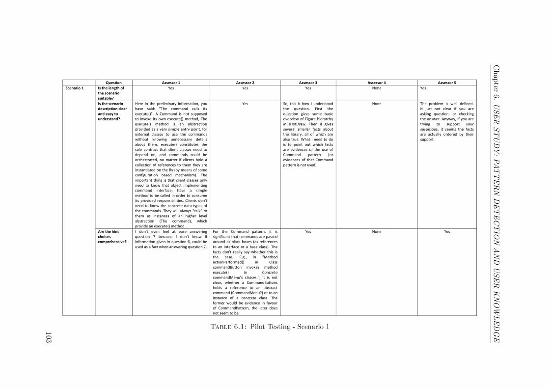
Chap
ter6.
US
ER
ST
UD
Y:
PA
TT
ER
ND
ET
EC
TIO
NA
ND
US
ER
KN
OW
LE
DG
E
Question Assessor 1 Assessor 2 Assessor 3 Assessor 4 Assessor 5
Scenario 1 Is the length of the scenario suitable?
Yes Yes Yes None Yes
Is the scenario description clear and easy to understand?
Here in the preliminary information, you have said: "The command calls its execute()". A Command is not supposed to invoke its own execute() method, The execute() method is an abstraction provided as a very simple entry point, for external classes to use the commands without knowing unnecessary details about them. execute() constitutes the sole contract that client classes need to depend on, and commands could be orchestrated, no matter if clients hold a collection of references to them they are instantiated on the fly (by means of some configuration based mechanism). The important thing is that client classes only need to know that object implementing command interface, have a simple method to be called in order to consume its provided responsibilities. Clients don't need to know the concrete data types of the commands. They will always "talk" to them as instances of an higher level abstraction (The command), which provide an execute() method.
Yes So, this is how I understood the question. First the question gives some basic overview of Figure hierarchy in JHotDraw. Then it gives several smaller facts about the library, all of which are also true. What I need to do is to point out which facts are evidences of the use of Command pattern (or evidences of that Command pattern is not used).
None The problem is well defined. It just not clear if you are asking question, or checking the answer. Anyway, if you are trying to support your suspicious, it seems the facts are actually ordered by their support.
Are the hint choices comprehensive?
I don't even feel at ease answering question 7 because I don't know if information given in question 6, could be used as a fact when answering question 7.
For the Command pattern, it is significant that commands are passed around as black boxes (as references to an interface or a base class). The facts don't really say whether this is the case. E.g., in "Method actionPerformed() in Class commandButton invokes method execute() in Concrete commandMenu’s classes.", it is not clear, whether a CommandButtons holds a reference to an abstract command (CommandMenu?) or to an instance of a concrete class. The former would be evidence in favour of CommandPattern, the later does not seem to be.
Yes None Yes
Table 6.1: Pilot Testing - Scenario 1103
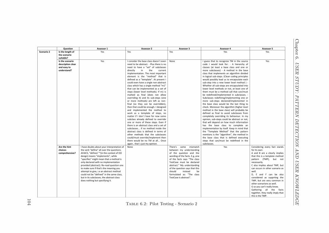
Chap
ter6.
US
ER
ST
UD
Y:
PA
TT
ER
ND
ET
EC
TIO
NA
ND
US
ER
KN
OW
LE
DG
E
Question Assessor 1 Assessor 2 Assessor 3 Assessor 4 Assessor 5
Scenario 2 Is the length of the scenario suitable?
Yes Yes Yes Yes Yes
Is the scenario description clear and easy to understand?
Yes I consider the base class doesn`t even need to be abstract. - Plus there is no need to have a "set" of subclasses directly in the current implementation. The most important element is the "method" that is defined as a "template". At present I could even have a single non-abstract class which has a single method "m1" that can be implemented as a set of steps (lower level methods). If m1 is marked as final (does not allow overriding it) and its sub-steps (one or more methods) are left as non-final (so they can be overridden), then that could be enough. I designed and implemented the method to work as a template of steps, no matter if I don`t have for now some subclass already defined to override one or more of these steps. Even if there is an abstract class and a set of subclasses... if no method inside the abstract class is defined in terms of other methods that the subclasses could/must override/implement then there would be no TM at all... Once again.. that`s just my opinion.
None I guess that to recognize TM in the source code I would look for: - A hierarchy of classes (at least a base class and one or more subclasses) - A method in the base class that implements an algorithm divided in logical sub-steps. (Clean coding principles would possibly lead us to encapsulate each sub-step into a new lower level method ) - Whether all sub-steps are encapsulated into lower level methods or not, at least one of them must be a method call that can/must be redefined/implemented in subclasses. - Subclasses redefining/implementing one or more sub-steps declared/implemented in the base class would be the last thing to check. Moreover the algorithm (higher level method in the base class) will probably be defined as final to avoid subclasses from completely overriding its behaviour. In my opinion, sub-steps could be abstract or not, that will depend on how much information has the base class to complete an implementation by itself. Keep in mind that the “Template Method” that the pattern mentions is the “algorithm”, the method in the base class that is defined executing steps that can/must be redefined in the subclasses.
Yes
Are the hint choices comprehensive?
I have doubts about your interpretation of the verb "define" all over the questions. AFAICS, "defines" *(in the context of OO design) means "implements", while "specifies" might mean that a method is only declared with no implementation provided (abstract). Re-read question one to make sure if that's the meaning you attempt to give, i.e an abstract method could not be "defined" in the same class, but in its subclasses, the abstract class does nothing but specifying it.
None There's some mismatch between my understanding of the question and the wording of the facts. E.g.,one of the facts says "The class TestCase must be declared abstract." My understanding of the question says that this should instead be formulated as: "The class TestCase is abstract".
Yes Considering every fact stands for its own: A and B are a clearly implies that this is a template method pattern (TMP), but not necessarily. C also implies about TMP, but can occurs in other scenario as well. D, E and F can be also considered as supprting the TMP, but are very common in other scenarions as well. G so you can't really know. Gathering all the facts together, they really imply that this is the TMP.
Table 6.2: Pilot Testing - Scenario 2
104
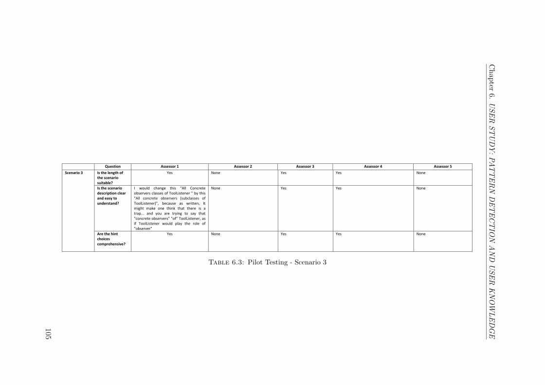
Chap
ter6.
US
ER
ST
UD
Y:
PA
TT
ER
ND
ET
EC
TIO
NA
ND
US
ER
KN
OW
LE
DG
E
Question Assessor 1 Assessor 2 Assessor 3 Assessor 4 Assessor 5
Scenario 3 Is the length of the scenario suitable?
Yes None Yes Yes None
Is the scenario description clear and easy to understand?
I would change this "All Concrete observers classes of ToolListener " by this "All concrete observers (subclasses of ToolListener)", because as written, It might make one think that there is a trap... and you are trying to say that "concrete observers" "of" ToolListener, as if ToolListener would play the role of "observer"
None Yes Yes None
Are the hint choices comprehensive?
Yes None Yes Yes None
Table 6.3: Pilot Testing - Scenario 3
105
Chapter 6. USER STUDY: PATTERN DETECTION AND USER KNOWLEDGE
6.3.2 Survey Operation
The next stage in the process of performing the survey is the survey operation [125].
In this phase the data survey answers are collected and organised. The two main
steps in the operation process are: (i) Survey preparation, where the participants
are selected and the questionnaire forms are distributed; (ii) Data collection, which
is carried out after the participants answer the questionnaire forms.
6.3.2.1 Preparation
A survey request letter was posted on LinkedIn and ResearchGate to request the
members of the selected groups to participate in the survey. This letter included
a description of the study, with a link for the on-line survey (See Appendix D.1).
Finding people who can be considered as experts and willing to participate was a
challenge. Therefore, every participant was asked to nominate and pass the on-line
survey link to colleagues who can be considered as familiar users of design patterns.
Some guidelines and factors were considered in order to motivate the participants to
take the exercise seriously, and to enhance the response rate [111]. Furthermore, a
set of ethical aspects were considered in the participants’ motivation process [125].
6.3.2.2 Collection
After posting the survey, it was opened on the 11th of July 2014 and closed on the
31st of August 2014. During the data collection process, the survey responses were
checked through a preliminary analysis to make sure the data were collected correctly
[125]. The result of the preliminary analysis of the data showed that the collected
answers were reasonable, and the survey was conducted in the desired way. Sixty
users participated in this empirical study. Forty-eight of them completed the on-line
survey successfully. In the final data analysis, twelve responses were eliminated due
to non-completion. The response rate was not calculated because, as mentioned
106
Chapter 6. USER STUDY: PATTERN DETECTION AND USER KNOWLEDGE
above in Section 6.3.1.1, the size of the population was unknown. The data were
collected and stored by the SurveyMonkey website database.
6.3.3 Data Analysis
The data collected in the previous step need to be analysed to draw a conclusion
based on this data. Typically, survey analysis is conducted from the quantitative
and qualitative data that have been generated by collecting the responses in the
operation phase. The quantitative data consists of numbers, while qualitative data
consists of words. In this case, the respondents responses were quantitatively anal-
ysed. A quantitative interpretation was carried out in order to draw the conclusion.
The quantitative data analysis includes the analysis of the descriptive statistics and
hypothesis testing [125]. This section introduces the statistical methods used to
analyse the collected answers. To understand the analysis procedure, it is impor-
tant to understand the most common measurement scales and data types. The data
can be described as either categorical data which can be analysed using the nominal
scale, or as a continuous data which can be analysed using the ordinal, the interval,
and the ratio scales. [25, 73, 125].
• The nominal scale maps the response categories to names or symbols. The
numbers represent the categories, and have no meaning except as the as-
signment for the text response. For example, the arbitrary numbers/labels
assignments for the gender (e.g. 1 = male, 2 = female).
• The ordinal scale is a more powerful scale that ranks the elements in order.
The numbers only specify the order, and each number has a value in a rela-
tionship to the other. Examples of the ordinal scale are the measures of “low”,
“medium”, “high”, and “greater than”.
• The interval scale uses numbers to specify the order and the distance between
the attributes. It is usually used when the data has a range and there is a
107
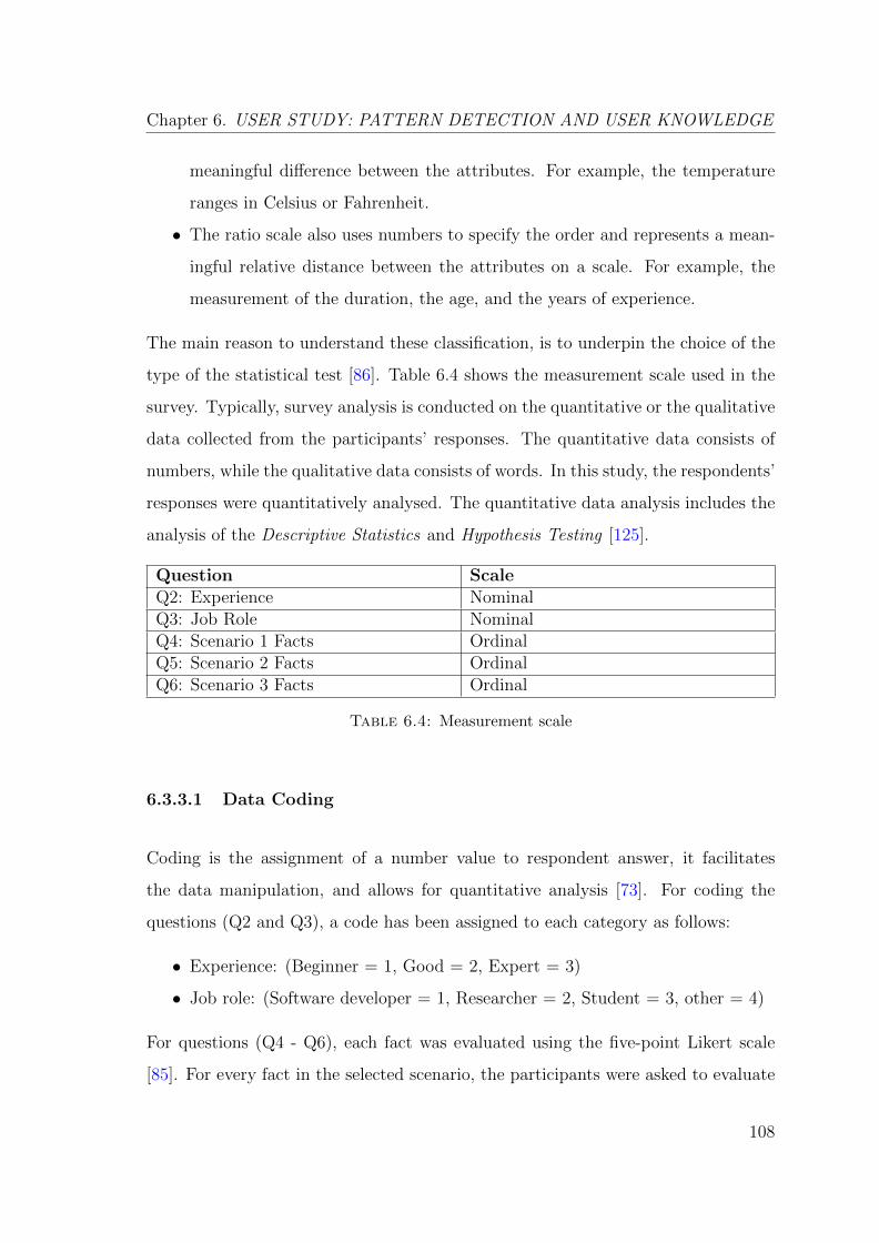
Chapter 6. USER STUDY: PATTERN DETECTION AND USER KNOWLEDGE
meaningful difference between the attributes. For example, the temperature
ranges in Celsius or Fahrenheit.
• The ratio scale also uses numbers to specify the order and represents a mean-
ingful relative distance between the attributes on a scale. For example, the
measurement of the duration, the age, and the years of experience.
The main reason to understand these classification, is to underpin the choice of the
type of the statistical test [86]. Table 6.4 shows the measurement scale used in the
survey. Typically, survey analysis is conducted on the quantitative or the qualitative
data collected from the participants’ responses. The quantitative data consists of
numbers, while the qualitative data consists of words. In this study, the respondents’
responses were quantitatively analysed. The quantitative data analysis includes the
analysis of the Descriptive Statistics and Hypothesis Testing [125].
Question ScaleQ2: Experience NominalQ3: Job Role NominalQ4: Scenario 1 Facts OrdinalQ5: Scenario 2 Facts OrdinalQ6: Scenario 3 Facts Ordinal
Table 6.4: Measurement scale
6.3.3.1 Data Coding
Coding is the assignment of a number value to respondent answer, it facilitates
the data manipulation, and allows for quantitative analysis [73]. For coding the
questions (Q2 and Q3), a code has been assigned to each category as follows:
• Experience: (Beginner = 1, Good = 2, Expert = 3)
• Job role: (Software developer = 1, Researcher = 2, Student = 3, other = 4)
For questions (Q4 - Q6), each fact was evaluated using the five-point Likert scale
[85]. For every fact in the selected scenario, the participants were asked to evaluate
108
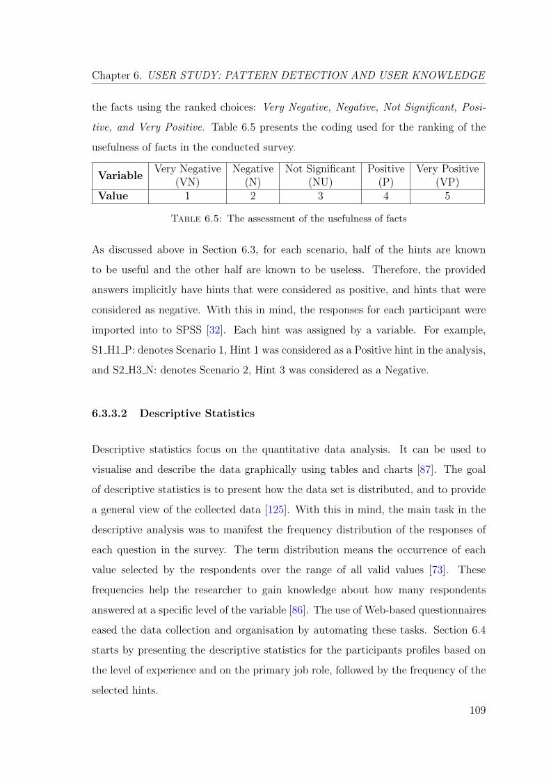
Chapter 6. USER STUDY: PATTERN DETECTION AND USER KNOWLEDGE
the facts using the ranked choices: Very Negative, Negative, Not Significant, Posi-
tive, and Very Positive. Table 6.5 presents the coding used for the ranking of the
usefulness of facts in the conducted survey.
VariableVery Negative
(VN)Negative
(N)Not Significant
(NU)Positive
(P)Very Positive
(VP)Value 1 2 3 4 5
Table 6.5: The assessment of the usefulness of facts
As discussed above in Section 6.3, for each scenario, half of the hints are known
to be useful and the other half are known to be useless. Therefore, the provided
answers implicitly have hints that were considered as positive, and hints that were
considered as negative. With this in mind, the responses for each participant were
imported into to SPSS [32]. Each hint was assigned by a variable. For example,
S1 H1 P: denotes Scenario 1, Hint 1 was considered as a Positive hint in the analysis,
and S2 H3 N: denotes Scenario 2, Hint 3 was considered as a Negative.
6.3.3.2 Descriptive Statistics
Descriptive statistics focus on the quantitative data analysis. It can be used to
visualise and describe the data graphically using tables and charts [87]. The goal
of descriptive statistics is to present how the data set is distributed, and to provide
a general view of the collected data [125]. With this in mind, the main task in the
descriptive analysis was to manifest the frequency distribution of the responses of
each question in the survey. The term distribution means the occurrence of each
value selected by the respondents over the range of all valid values [73]. These
frequencies help the researcher to gain knowledge about how many respondents
answered at a specific level of the variable [86]. The use of Web-based questionnaires
eased the data collection and organisation by automating these tasks. Section 6.4
starts by presenting the descriptive statistics for the participants profiles based on
the level of experience and on the primary job role, followed by the frequency of the
selected hints.
109
Chapter 6. USER STUDY: PATTERN DETECTION AND USER KNOWLEDGE
6.3.3.3 Hypothesis Testing
Hypothesis testing is a statical method used to evaluate the hypothesis and to assist
in making the decision by using a sample data. The objective of hypothesis testing
is to see whether it is possible to reject a certain null hypothesis H0 based on the
sample from some statistical distribution [125]. The null hypothesis that represents
the case is generally assumed true until an evidence indicates otherwise. In that case,
the null hypothesis H0 is rejected and the alternative hypothesis HA is accepted. The
process followed for testing the hypothesis is as follows:
1. Define the scientific hypothesis that covers the aim of the conducted investi-
gation.
2. Derive the statistical hypothesis, including the null H0 and the alternative
hypothesis HA.
3. Decide what kind of testing is more appropriate to test the case.
4. Select the test technique to apply.
5. Accept or reject the null hypothesis based on the data analysis.
6.3.3.4 Test of Normality
Tests can be classified into a parametric and a non-parametric test [125]. The
parametric test assumes that the data is normally distributed. The non-parametric
test can be used when the data does not meet the assumptions needed to use the
parametric test [86]. The selection of different testing methods is carried with respect
to the type of the test either parametric or non-parametric. Therefore, it is necessary
to check whether the observed distribution fits the normal distribution based on the
respondents’ responses in the three selected scenarios. Let’s assume the following:
H0: P > 0.05. the observed distribution fits the normal distribution.
HA: P ≤ 0.05. the observed distribution does not fit the normal distribution.
110
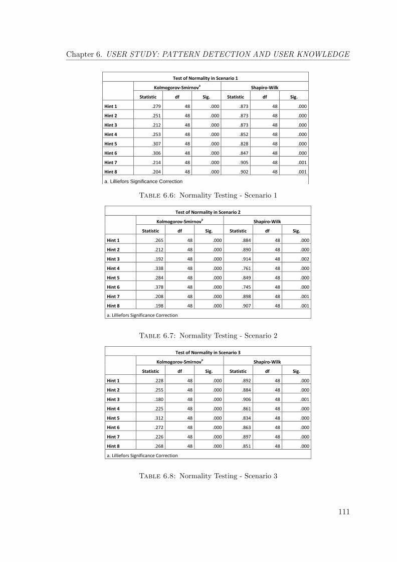
Chapter 6. USER STUDY: PATTERN DETECTION AND USER KNOWLEDGE
Test of Normality in Scenario 1
Kolmogorov-Smirnova Shapiro-Wilk
Statistic df Sig. Statistic df Sig.
Hint 1 .279 48 .000 .873 48 .000
Hint 2 .251 48 .000 .873 48 .000
Hint 3 .212 48 .000 .873 48 .000
Hint 4 .253 48 .000 .852 48 .000
Hint 5 .307 48 .000 .828 48 .000
Hint 6 .306 48 .000 .847 48 .000
Hint 7 .214 48 .000 .905 48 .001
Hint 8 .204 48 .000 .902 48 .001
a. Lilliefors Significance Correction
Table 6.6: Normality Testing - Scenario 1
Test of Normality in Scenario 2
Kolmogorov-Smirnova Shapiro-Wilk
Statistic df Sig. Statistic df Sig.
Hint 1 .265 48 .000 .884 48 .000
Hint 2 .212 48 .000 .890 48 .000
Hint 3 .192 48 .000 .914 48 .002
Hint 4 .338 48 .000 .761 48 .000
Hint 5 .284 48 .000 .849 48 .000
Hint 6 .378 48 .000 .745 48 .000
Hint 7 .208 48 .000 .898 48 .001
Hint 8 .198 48 .000 .907 48 .001
a. Lilliefors Significance Correction
Table 6.7: Normality Testing - Scenario 2
Test of Normality in Scenario 3
Kolmogorov-Smirnova Shapiro-Wilk
Statistic df Sig. Statistic df Sig.
Hint 1 .228 48 .000 .892 48 .000
Hint 2 .255 48 .000 .884 48 .000
Hint 3 .180 48 .000 .906 48 .001
Hint 4 .225 48 .000 .861 48 .000
Hint 5 .312 48 .000 .834 48 .000
Hint 6 .272 48 .000 .863 48 .000
Hint 7 .226 48 .000 .897 48 .000
Hint 8 .268 48 .000 .851 48 .000
a. Lilliefors Significance Correction
Table 6.8: Normality Testing - Scenario 3
111

Chapter 6. USER STUDY: PATTERN DETECTION AND USER KNOWLEDGE
Tables 6.6, 6.7, and 6.8 show that the results have significant differences (p ≤ 0.05).
Thus, the null hypothesis is rejected. The observed distribution from the three
scenarios do not fit the normal distribution. Therefore, a non-parametric test was
used in the analysis of the hypothesis in this study. This is because the collected
data did not show a normal distribution based on the normality testing of the three
scenarios.
6.4 Results & Discussion
Before conducting the data analysis, it was essential to be acquainted with the
distributions of the respondents. Thus, analysing the collected responses began with
the respondents profiles based on the level of experience and on the primary job role.
In detail, the composition of the respondents was analysed by using the demographic
questions (Q2 - Q3). The majority of the respondents were software developers (61
%) and researchers (25 %). The distribution of the respondents based on the level
of experience is; beginner (33 %), good (52 %), and expert (15 %). Figure 6.2 and
6.3 summarise the distribution of the respondents based on their job role and level
of experience.
61%
25%
6%
8%
Software Developer
Researcher
Student
Other
Figure 6.2: Profile of respondents: Job Role
112

Chapter 6. USER STUDY: PATTERN DETECTION AND USER KNOWLEDGE
33%
52%
15%
Beginner
Good
Expert
Figure 6.3: Profile of respondents: Level of experience
6.4.1 The Frequency of Hints
The frequencies of the selection of useful hints in each scenario (Q4 - Q6) are pre-
sented as follows. Table 6.9 shows the frequency of the selection of hints in percentage
of the number of respondents ranking. The left column of Table 6.9 shows the hints
in the three scenarios, along with the ranking scale values of these hints from left to
right (VN,.., VP). The results show that the participants were able to successfully
rate the positive hints as useful hints, and the negative hints as useless hints.
In the first scenario, the positive hints are H2, H3, H5, and H6. On the other hand,
the negative hints are H1, H4, H7, and H8. It can be seen the positive group were
ranked significantly more useful than the negative group. For example, the positive
hint H2 was rated in a percentage of 43.8 % as useful, and 14.6 as very useful (58.4
% useful). The negative hint H1 was rated with percentage of 16.7 % as not at all
useful, and 45.8 % as not very useful (62.5 % useless).
In the second scenario, the positive hints are H1, H2, H4, and H6. On the other
hand, the negative hints are H3, H5, H7, and H8. Similarly in the first scenario,
the overall ranking of positive hints group as useful was very positive. Furthermore,
the ranking of the negative hints group as useless shows that the respondents were
able to define these hints as useless for a given type of pattern. Finally, the third
113
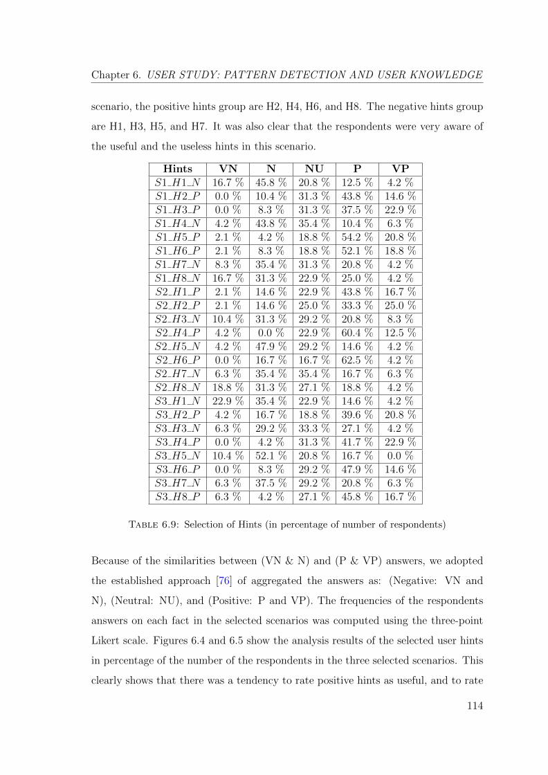
Chapter 6. USER STUDY: PATTERN DETECTION AND USER KNOWLEDGE
scenario, the positive hints group are H2, H4, H6, and H8. The negative hints group
are H1, H3, H5, and H7. It was also clear that the respondents were very aware of
the useful and the useless hints in this scenario.
Hints VN N NU P VPS1 H1 N 16.7 % 45.8 % 20.8 % 12.5 % 4.2 %S1 H2 P 0.0 % 10.4 % 31.3 % 43.8 % 14.6 %S1 H3 P 0.0 % 8.3 % 31.3 % 37.5 % 22.9 %S1 H4 N 4.2 % 43.8 % 35.4 % 10.4 % 6.3 %S1 H5 P 2.1 % 4.2 % 18.8 % 54.2 % 20.8 %S1 H6 P 2.1 % 8.3 % 18.8 % 52.1 % 18.8 %S1 H7 N 8.3 % 35.4 % 31.3 % 20.8 % 4.2 %S1 H8 N 16.7 % 31.3 % 22.9 % 25.0 % 4.2 %S2 H1 P 2.1 % 14.6 % 22.9 % 43.8 % 16.7 %S2 H2 P 2.1 % 14.6 % 25.0 % 33.3 % 25.0 %S2 H3 N 10.4 % 31.3 % 29.2 % 20.8 % 8.3 %S2 H4 P 4.2 % 0.0 % 22.9 % 60.4 % 12.5 %S2 H5 N 4.2 % 47.9 % 29.2 % 14.6 % 4.2 %S2 H6 P 0.0 % 16.7 % 16.7 % 62.5 % 4.2 %S2 H7 N 6.3 % 35.4 % 35.4 % 16.7 % 6.3 %S2 H8 N 18.8 % 31.3 % 27.1 % 18.8 % 4.2 %S3 H1 N 22.9 % 35.4 % 22.9 % 14.6 % 4.2 %S3 H2 P 4.2 % 16.7 % 18.8 % 39.6 % 20.8 %S3 H3 N 6.3 % 29.2 % 33.3 % 27.1 % 4.2 %S3 H4 P 0.0 % 4.2 % 31.3 % 41.7 % 22.9 %S3 H5 N 10.4 % 52.1 % 20.8 % 16.7 % 0.0 %S3 H6 P 0.0 % 8.3 % 29.2 % 47.9 % 14.6 %S3 H7 N 6.3 % 37.5 % 29.2 % 20.8 % 6.3 %S3 H8 P 6.3 % 4.2 % 27.1 % 45.8 % 16.7 %
Table 6.9: Selection of Hints (in percentage of number of respondents)
Because of the similarities between (VN & N) and (P & VP) answers, we adopted
the established approach [76] of aggregated the answers as: (Negative: VN and
N), (Neutral: NU), and (Positive: P and VP). The frequencies of the respondents
answers on each fact in the selected scenarios was computed using the three-point
Likert scale. Figures 6.4 and 6.5 show the analysis results of the selected user hints
in percentage of the number of the respondents in the three selected scenarios. This
clearly shows that there was a tendency to rate positive hints as useful, and to rate
114
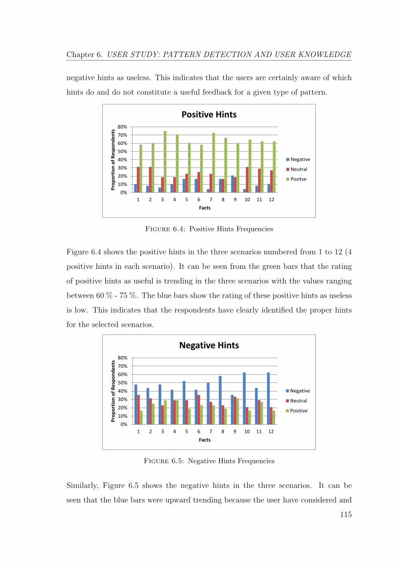
Chapter 6. USER STUDY: PATTERN DETECTION AND USER KNOWLEDGE
negative hints as useless. This indicates that the users are certainly aware of which
hints do and do not constitute a useful feedback for a given type of pattern.
0%
10%
20%
30%
40%
50%
60%
70%
80%
1 2 3 4 5 6 7 8 9 10 11 12
Pro
po
rtio
n o
f R
esp
on
de
nts
Facts
Positive Hints
Negative
Neutral
Positve
Figure 6.4: Positive Hints Frequencies
Figure 6.4 shows the positive hints in the three scenarios numbered from 1 to 12 (4
positive hints in each scenario). It can be seen from the green bars that the rating
of positive hints as useful is trending in the three scenarios with the values ranging
between 60 % - 75 %. The blue bars show the rating of these positive hints as useless
is low. This indicates that the respondents have clearly identified the proper hints
for the selected scenarios.
0%
10%
20%
30%
40%
50%
60%
70%
80%
1 2 3 4 5 6 7 8 9 10 11 12
Pro
po
rtio
n o
f R
esp
on
de
nts
Facts
Negative Hints
Negative
Neutral
Positive
Figure 6.5: Negative Hints Frequencies
Similarly, Figure 6.5 shows the negative hints in the three scenarios. It can be
seen that the blue bars were upward trending because the user have considered and
115
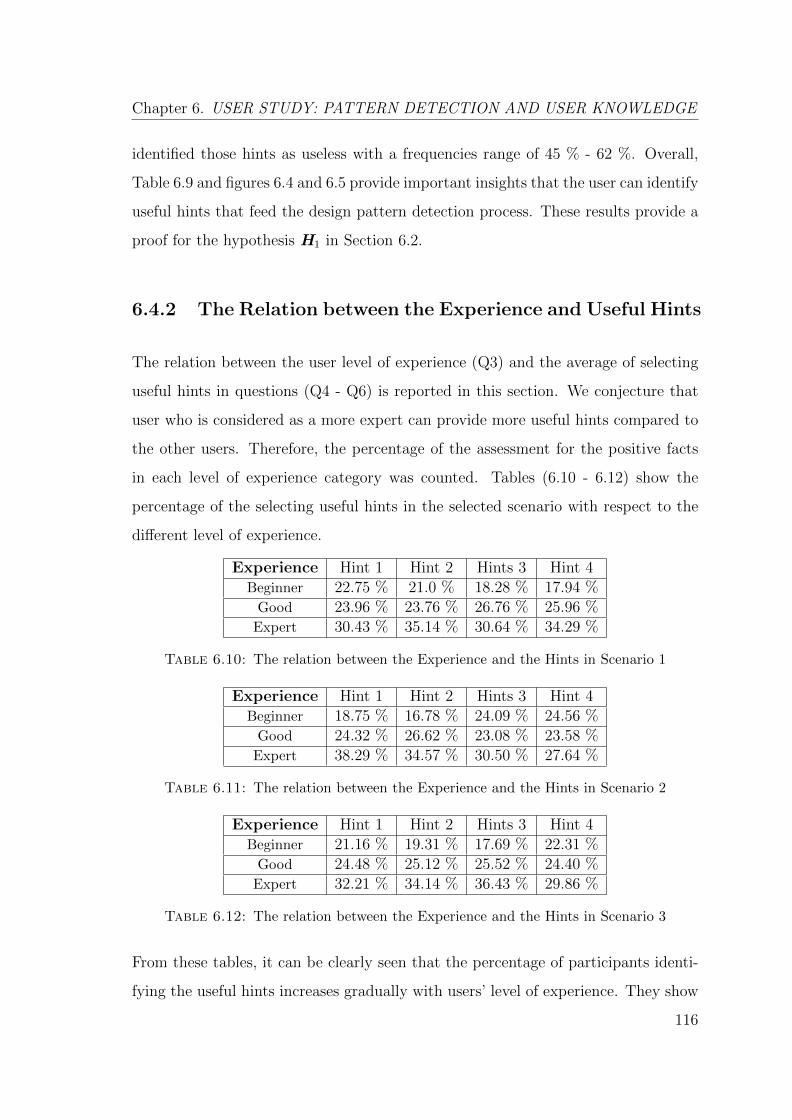
Chapter 6. USER STUDY: PATTERN DETECTION AND USER KNOWLEDGE
identified those hints as useless with a frequencies range of 45 % - 62 %. Overall,
Table 6.9 and figures 6.4 and 6.5 provide important insights that the user can identify
useful hints that feed the design pattern detection process. These results provide a
proof for the hypothesis H1 in Section 6.2.
6.4.2 The Relation between the Experience and Useful Hints
The relation between the user level of experience (Q3) and the average of selecting
useful hints in questions (Q4 - Q6) is reported in this section. We conjecture that
user who is considered as a more expert can provide more useful hints compared to
the other users. Therefore, the percentage of the assessment for the positive facts
in each level of experience category was counted. Tables (6.10 - 6.12) show the
percentage of the selecting useful hints in the selected scenario with respect to the
different level of experience.
Experience Hint 1 Hint 2 Hints 3 Hint 4Beginner 22.75 % 21.0 % 18.28 % 17.94 %
Good 23.96 % 23.76 % 26.76 % 25.96 %Expert 30.43 % 35.14 % 30.64 % 34.29 %
Table 6.10: The relation between the Experience and the Hints in Scenario 1
Experience Hint 1 Hint 2 Hints 3 Hint 4Beginner 18.75 % 16.78 % 24.09 % 24.56 %
Good 24.32 % 26.62 % 23.08 % 23.58 %Expert 38.29 % 34.57 % 30.50 % 27.64 %
Table 6.11: The relation between the Experience and the Hints in Scenario 2
Experience Hint 1 Hint 2 Hints 3 Hint 4Beginner 21.16 % 19.31 % 17.69 % 22.31 %
Good 24.48 % 25.12 % 25.52 % 24.40 %Expert 32.21 % 34.14 % 36.43 % 29.86 %
Table 6.12: The relation between the Experience and the Hints in Scenario 3
From these tables, it can be clearly seen that the percentage of participants identi-
fying the useful hints increases gradually with users’ level of experience. They show
116
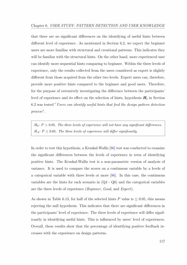
Chapter 6. USER STUDY: PATTERN DETECTION AND USER KNOWLEDGE
that there are no significant differences on the identifying of useful hints between
different level of experience. As mentioned in Section 6.2, we expect the beginner
users are more familiar with structural and creational patterns. This indicates they
will be familiar with the structural hints. On the other hand, more experienced user
can identify more sequential hints comparing to beginner. Within the three levels of
experience, only the results collected from the users considered as expert is slightly
different from those acquired from the other two levels. Expert users can, therefore,
provide more positive hints compared to the beginner and good users. Therefore,
for the purpose of extensively investigating the difference between the participants’
level of experience and its effect on the selection of hints, hypothesis H2 in Section
6.2 was tested ”Users can identify useful hints that feed the design pattern detection
process”.
H0: P > 0.05. The three levels of experience will not have any significant differences.
HA: P ≤ 0.05. The three levels of experience will differ significantly.
In order to test this hypothesis, a Kruskal-Wallis [86] test was conducted to examine
the significant differences between the levels of experience in term of identifying
positive hints. The Kruskal-Wallis test is a non-parametric version of analysis of
variance. It is used to compare the scores on a continuous variable by a levels of
a categorical variable with three levels or more [86]. In this case, the continuous
variables are the hints for each scenario in (Q4 - Q6) and the categorical variables
are the three levels of experience (Beginner, Good, and Expert).
As shown in Table 6.13, for half of the selected hints P value is ≤ 0.05, this means
rejecting the null hypothesis. This indicates that there are significant differences in
the participants’ level of experience. The three levels of experience will differ signif-
icantly in identifying useful hints. This is influenced by users’ level of experiences.
Overall, these results show that the percentage of identifying positive feedback in-
creases with the experience on design patterns.
117
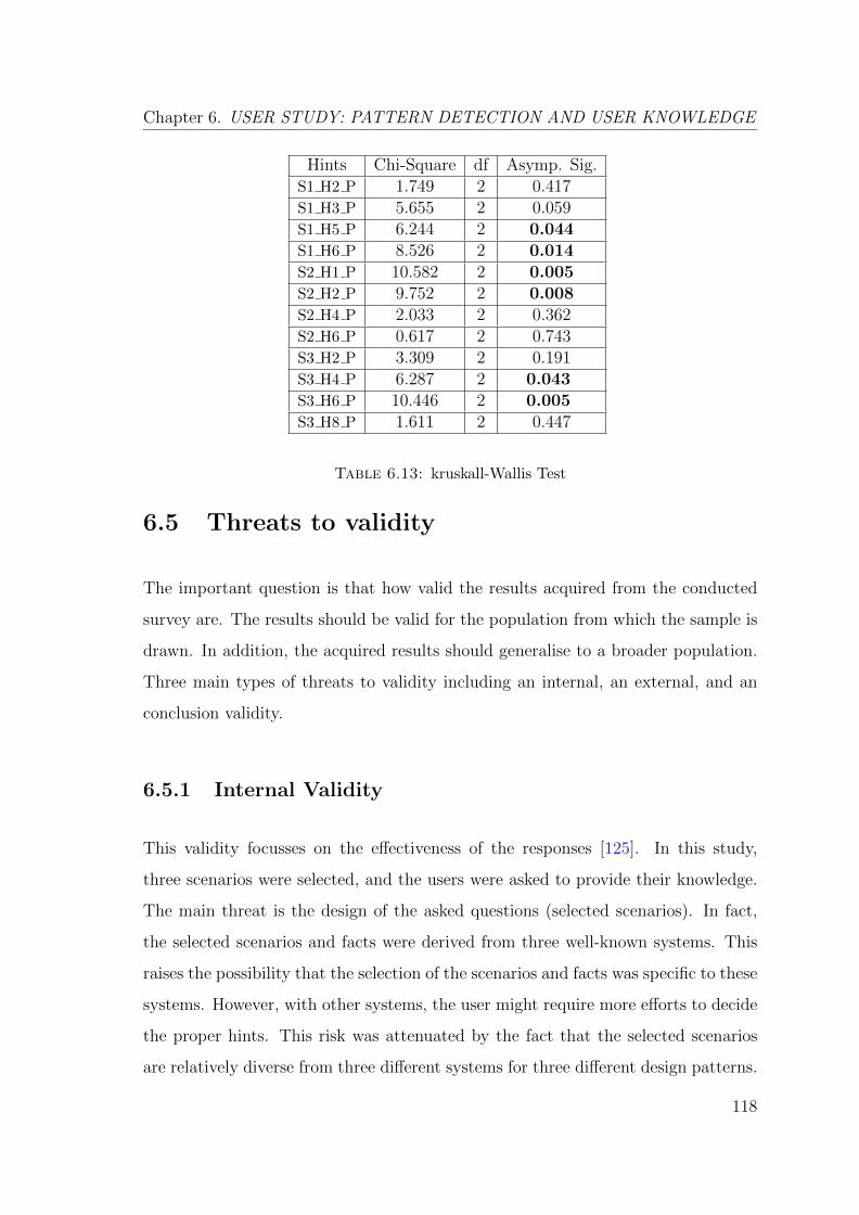
Chapter 6. USER STUDY: PATTERN DETECTION AND USER KNOWLEDGE
Hints Chi-Square df Asymp. Sig.S1 H2 P 1.749 2 0.417S1 H3 P 5.655 2 0.059S1 H5 P 6.244 2 0.044S1 H6 P 8.526 2 0.014S2 H1 P 10.582 2 0.005S2 H2 P 9.752 2 0.008S2 H4 P 2.033 2 0.362S2 H6 P 0.617 2 0.743S3 H2 P 3.309 2 0.191S3 H4 P 6.287 2 0.043S3 H6 P 10.446 2 0.005S3 H8 P 1.611 2 0.447
Table 6.13: kruskall-Wallis Test
6.5 Threats to validity
The important question is that how valid the results acquired from the conducted
survey are. The results should be valid for the population from which the sample is
drawn. In addition, the acquired results should generalise to a broader population.
Three main types of threats to validity including an internal, an external, and an
conclusion validity.
6.5.1 Internal Validity
This validity focusses on the effectiveness of the responses [125]. In this study,
three scenarios were selected, and the users were asked to provide their knowledge.
The main threat is the design of the asked questions (selected scenarios). In fact,
the selected scenarios and facts were derived from three well-known systems. This
raises the possibility that the selection of the scenarios and facts was specific to these
systems. However, with other systems, the user might require more efforts to decide
the proper hints. This risk was attenuated by the fact that the selected scenarios
are relatively diverse from three different systems for three different design patterns.
118
Chapter 6. USER STUDY: PATTERN DETECTION AND USER KNOWLEDGE
However, it is part of the future work to conduct a study using a wider range of
systems and design patterns.
6.5.2 External Validity
This validity concerns about to which extent the results of a study can be held to
be true for other people, places, or times. In particular, external validity focuses on
the completeness of the responses [125]. The main point is how does the sample was
selected as a representative for the population. As was discussed in Section 6.3.1.1,
there is no available group or a well-known population for researchers or experts
in the area of design pattern detection. Thus, the current research networks were
used to simulate the sampling process. In the current study, the bias in selecting
participants was mitigated by posting the survey on selected groups and asking the
participants to nominate others to participate. In future work, it would be inter-
esting to select expert users from a well-known population (i.e. software students,
developers, etc.).
6.5.3 Conclusion validity
This validity concerns with the issues that affect the ability to draw the correct con-
clusion [125]. As discussed before, this study of design patterns aimed to investigate
the experiences of professionals with design patterns in the domain of software engi-
neering. However, if the users who have participated were not experts in the domain
system or the design patterns, this will affect the conclusion that was derived upon
the collected data from their responses. There would be a useful input on the utility
of the approach if the users were actually experts. The results might have differed
if students were surveyed as part of the study. The students’ responses reflect the
students’ ability in understanding design problems with patterns and interpreting
the impact of patterns. Students having minimum programming skills might find it
119
Chapter 6. USER STUDY: PATTERN DETECTION AND USER KNOWLEDGE
difficult to understand the design pattern through the code. The students’ responses
are associated with the effectiveness of teaching them the design patterns in a soft-
ware engineering course. Some design patterns are less popular than others. This
indicates that software students spend more time on patterns, which are fundamen-
tally difficult to understand [28]. Students might find it difficult to relate the applied
design patterns to specific source code elements. This is possibly due to the fact that
most patterns are presented in Gamma et al. [54] as solutions to known implemen-
tation problems rather than as a treatment of design issues in reverse engineering
manner. In other words, design patterns are presented as a consequence rather than
a goal of pattern application. This observation can be valuable in redesigning and
in enhancing the design pattern courses.
6.6 Summary
An empirical study was conducted in this chapter. Sixty expert users participated
in this study with forty-eight users successfully completed the survey (incomplete
surveys were discarded). This study aimed to highlight the importance of involv-
ing user knowledge in the design pattern detection. The survey was conducted to
investigate the relation between the user and the design pattern detection process,
and how does the expert users can supplement useful hints in the detection pro-
cess. The main reason for this study is to provide evidence of the importance of
users’ involvements in the design pattern detection process. The collected data were
quantitatively analysed using descriptive statistics and hypothesis testing. A non-
parametric method test was applied for the hypothesis testing, which aimed to study
the relation between the user level of experience and the amount of the provided
useful hints. The results indicated that the user can feed the detection process with
useful hints to enhance the detection of the design patterns in the source code. In
addition, the amount of this knowledge is influenced by users’ level of experiences.
120

Chapter 7
CONCLUSIONS AND FUTURE
WORK
This chapter outlines the conclusions and the future work of the research presented
in the thesis. Section 7.1 presents a summary of the research and its outcomes.
Section 7.2 discusses the conclusions of the conducted research. Finally, Section 7.3
lists some suggestions for further research directions.
7.1 Overall Summary
The work in thesis highlights the important role that can be played by the ex-
perts in the design pattern detection process. It argues that this process needs to
be considered as an iterative and user-driven process. In order to achieve this, a
constraint-based framework was built to provide the user knowledge in the form
of a small amount of useful hints. The proposed approach is compatible with the
existing constraint-based pattern detection approaches, and can act as a comple-
mentary ‘layer’ to enable additional feedback from the user. The proposed approach
was evaluated using an experimental case study that applied it to three open-source
121
Chapter 7. CONCLUSIONS AND FUTURE WORK
systems. A more substantive controlled user study that involved a broader range
of participants was also conducted for the evaluation of the proposed approach. It
explored the process of hint selection, with a view to determining which hints are
especially useful in which contexts.
• Chapter 2 introduced the history of design patterns, and explained how de-
sign patterns have been interpreted in context of object-oriented design. The
general concept of design patterns, their classification, and relevance were dis-
cussed in this chapter. Finally, this chapter discussed the impact of using
design patterns, the design pattern implementation, and the identification of
design patterns.
• Chapter 3 covered the main concepts related to the design pattern detection
process, and reviewed some of the work related to this area. Different ap-
proaches were built to date based on different detection techniques. Some of
these approaches are tool-supported. The key challenges and problems that
currently face the available approaches of design pattern detection are high-
lighted. These challenges constitutes the main motivation for the research
topic in this thesis.
• Chapter 4 presented the proposed approach which seeks to enable the user
to feed small ‘hints’ into the detection process. This is unlike most of the
existing tools, which permit a limited degree of user-interaction. The proposed
approach enables the user to be much more expressive, whilst remaining easy
to use. Hints can provide information about the dynamic behaviour, or provide
partial knowledge about the pattern implementations themselves. The use of
hints can gradually guide the constraint solver towards a more accurate set of
detected pattern instances.
• Chapter 5 presented the experiments of the proposed approach. The proposed
approach was applied to a selections of openly available software systems.
The specific research question was “ To what extent does the use of hints
lead to an increase in the accuracy of the design pattern detection results?”.
122
Chapter 7. CONCLUSIONS AND FUTURE WORK
The evaluation results indicated that this approach can yield a significant
improvement in the detection accuracy based on a relatively small amount of
input fed by the developer.
• Chapter 6 covered the user study, which also aimed to elaborate upon the
results of Chapter 5. The specific research question was “Are users certainly
aware of which hints that do and do not constitute a useful feedback for a given
type of pattern?”. The study findings indicated that users can supplement the
design pattern detection process with a positive feedback that can enhances
the detection of design pattern.
7.2 Conclusions
Aims This thesis was founded on the observation that, in order to produce more
accurate results, it is necessary to actively involve the expert user in the pattern
detection process. The aim was to provide a structured process involving the user
expert to complement the existing constraint-based pattern detection techniques. It
proposed a framework that enables the user to supply their knowledge in the form
of ‘hints’, fed as small facts about the source code or the pattern implementations
that can enhance or curtail the results.
Findings The approach was applied to three openly available systems for evalu-
ation. The evaluation case study results indicated that user knowledge enhances
the detection process and can eliminate the detection of false positives. The use of
hints can, therefore, substantially increase the accuracy of the detected patterns. A
user study was also conducted for evaluation. This study involved a broader range
of expert users. The results of this study indicated that there was a tendency to
rate positive hints as useful and to rate negative hints as useless. This suggests that
users are certainly aware of which hints do and do not constitute a useful feedback
for a given type of pattern.
123
Chapter 7. CONCLUSIONS AND FUTURE WORK
The evaluation case study findings enhance our understanding of how the user knowl-
edge feeds the detection process. On the other hand, the user study findings could
be used to show that the expert user can supplement the design pattern detection
process with useful hints. These hints can enhance the detection of design pat-
tern instances in the source code. These hints can include the knowledge about
the structure, the behaviour, and the possible implementation deviations from tra-
ditional design pattern specifications. Therefore, it can be concluded that pattern
detection must necessarily be a user-driven process. The results of this research sup-
port the idea that the user must be provided with as much opportunity as possible
to contribute their knowledge about design pattern occurrences.
7.2.1 Findings Significance in Design Pattern Detection
Fully automated pattern detection techniques are intrinsically limited, especially
when it comes to the detection of the behavioural patterns. Current design pattern
detection techniques and tools do not produce accurate results because they do
not enable sufficient intervention from users. This research has shown that how a
limited amount of user input can complement automated detection. It enhances our
understanding of the important role of the user expert in the detection process. The
user-driven approach proposed in this thesis provides a suitable basis for bridging
the gap, by enabling the user to supply the information that is not available to those
techniques.
This research strengthens the idea that the use of micro-structures has a global
usefulness to the design pattern detection process [49, 92, 93, 112, 113]. However,
micro-structures alone are not enough to enhance the detection results. The inte-
gration of the user in an iterative user-driven process helps to refine and gradually
enhances the detection results. The contribution is the iterative process where the
user can refine the detection results in an incremental manner. Future detection
techniques should therefore concentrate on considering the role of the user expert
124
Chapter 7. CONCLUSIONS AND FUTURE WORK
in the detection process. This research confirm that there is a need for hybrid
approaches that combines the automatic tools with the user inputs.
The general approach of gradually acquiring constraints has previously been suc-
cessfully applied to software engineering [67]. It has shown that it is possible
to significantly improve the accuracy of a solution (in the context of software re-
modularisation area) with a relatively small facts from the developer. In the same
manner, this research will serve as the basis for future studies in the design pattern
detection area. This research provides an evidence that in order to produce more
accurate detection results, the detection process cannot be considered as a fully
automated process.
7.2.2 Findings Significance in Software Maintenance
In object-oriented legacy systems, the source code can contain thousands of classes
and millions of lines of codes. Furthermore, design documents are often missing, or
may not accurately match the source code [90]. Therefore, the absence of a valid
documentation has a bad influence on the process of understanding and compre-
hending these systems. This research extends our knowledge of the use of design
patterns, which can provide a better understanding of a legacy system program code.
If the software maintainer is aware of the patterns used in the code, this will assist in
understanding the system requirements and in considering new requirements from
the reversed design patterns.
The findings of this thesis could be used to provide insights into the source code,
which can help the maintainer to understand the analysed system. The recovery of
the source code design and architecture makes the maintenance task easier. It helps
inspecting the source code artefacts in order to gain a sufficient level of knowledge
about the analysed system design and architecture. Furthermore, understanding and
organising the source code as a set of well-known structures (GoF Design patterns)
125
Chapter 7. CONCLUSIONS AND FUTURE WORK
gives the software maintainer a faster firm grasp of the whole system structure and
organisation. This research helps in organising the legacy system around recurring
patterns (represented as a set of classes and objects), and will assist in the program
comprehension. This gives the maintainers and the developers the opportunity to
be more productive in the process of understanding legacy systems. Moreover, un-
derstanding legacy system as a set of design patterns facilitates the communication
between software designers, software developers, and software maintainers by using
a common design patterns vocabulary.
The research findings confirm previous findings and contribute additional evidence
that the detection of design patterns enhances the documentation process. Further-
more, the detection of design patterns facilitates the modifications process by adding
new functionality. It also accelerates the software development process by grouping
the software based on well-known patterns. Future research should, therefore, focus
on the integration of the proposed framework with the software development process
in a reengineering cycle. This will augment the software development and makes
this approach more useful in facilitating the software reengineering tasks.
7.3 Future Research Directions
This research revealed many questions the needs to be investigated in further studies.
The following is a summary for the possible open research directions:
• Evaluation: The approach was evaluated only on three systems. Those sys-
tems may not be sufficiently representative. It is, therefore, part of the future
work to apply the proposed approach to a wider range of different software sys-
tems. Moreover, it would be interesting to extend the conducted evaluation
experiments to evaluate the approach against all the GoF [54] design patterns.
126
Chapter 7. CONCLUSIONS AND FUTURE WORK
• Hint Templates: The selection of hints was systematised by using a set hint-
templates. However, hint-templates are not meant to be complete or perfect.
In the future work, the top priority is to facilitate the addition of useful hints.
It would be interesting to generate more useful hint templates. For example:
collecting more hints from different expert users. This could be achieved by
conducting another survey with more open questions. The participants of this
study would be expected to select a specific pattern and use their knowledge
to create hints.
• Detection Workflow: This research highlights the role of the user expert in
the detection process. Further studies need to be carried out in order to create
more concrete guidelines for the involvement of the user expert in the design
pattern detection process, typically in the form of an organised workflow. This
can be achieved by providing not only templates of frequent solutions, but also
a straightforward approach for deciding which hints to select. Moreover, it
would be of a great help to provide a facility that allow the users to navigate
through the pattern candidates and go back to the code editor where the
pattern is implemented.
• Pattern Variants Catalogue: As discussed in Section 5.5.1, each pattern
can be represented by different code styles. It would be useful to provide
a definition for the possible common pattern implementations variants. A
greater focus on design pattern specifications and its implementations could
produce interesting findings that account more for creating a catalogue of
design pattern implementations variants. This will enhance the user awareness
of different alternatives for each design pattern.
• Empirical Directions: The empirical study in Chapter 5 raised many ques-
tions that need further investigations. (i) Investigate whether the users want
to use the framework with other source code related tools to facilitate their pro-
gramming tasks; (ii) Some hints were considered as not being useful, it would
127
Chapter 7. CONCLUSIONS AND FUTURE WORK
be interesting to investigate how these hints influence the user decisions. The
investigation of these two questions will help to create a more concrete hint
selection guidance.
• Expert Users Population: In future research, it would be interesting to
select expert users from a well-known population (i.e. software students, de-
velopers, etc.). This will help to extract a more accurate generalisation from
the acquired results.
• Expressing Constraints: The user feedback is provided in the form of hints.
This feedback needs to take the form of additional constraints that can be
added to the constraint solver. In further research, one might consider some
other techniques used to support the user feedback such as Aspect-Oriented
Software Development (AOSD) as a way of expressing constraints.
• P-MARt Patterns: Some new extra patterns are identified as true positive
instances during the manual validation of the acquired results in the chosen
systems in Chapter 5. These pattern instances need to be checked with P-
MARt [59] team in order to verify if they are true positives or false positives.
128

Appendix A
Implementation
A.1 InFamix (.mse) file
129

Appendix F. Implementation
(
(FAMIX.JavaSourceLanguage)
(FAMIX.Namespace (id: 9)
(name '')
)
(FAMIX.Class (id: 11)
(sourceAnchor (ref: 112))
(parentPackage (ref: 7))
(container (ref: 9))
(name 'FlipUpCommand')
)
(FAMIX.Inheritance (id: 113)
(subclass (ref: 11))
(superclass (ref: 12))
)
(FAMIX.Class (id: 12)
(sourceAnchor (ref: 114))
(parentPackage (ref: 7))
(container (ref: 9))
(name 'Command')
(isAbstract true)
)
(FAMIX.Inheritance (id: 115)
(subclass (ref: 12))
(superclass (ref: 27))
)
(FAMIX.Class (id: 32)
(sourceAnchor (ref: 116))
(parentPackage (ref: 7))
(container (ref: 9))
(name 'Switch')
)
(FAMIX.Inheritance (id: 117)
(subclass (ref: 32))
(superclass (ref: 27))
)
(FAMIX.Class (id: 16)
(sourceAnchor (ref: 118))
(parentPackage (ref: 7))
(container (ref: 9))
(name 'Light')
(
)
(FAMIX.Inheritance (id: 119)
(subclass (ref: 16))
(superclass (ref: 27))
)
(FAMIX.Class (id: 67)
(sourceAnchor (ref: 120))
(parentPackage (ref: 7))
(container (ref: 9))
(name 'FlipDownCommand')
)
(FAMIX.Inheritance (id: 121)
(subclass (ref: 67))
(superclass (ref: 12))
)
(FAMIX.Class (id: 80)
(sourceAnchor (ref: 122))
(parentPackage (ref: 7))
(container (ref: 9))
(name 'PressSwitch')
)
(FAMIX.Inheritance (id: 123)
(subclass (ref: 80))
(superclass (ref: 27))
)
(FAMIX.Attribute (id: 55)
(name 'out')
(parentType (ref: 56))
(declaredType (ref: 3))
(isPackage true)
)
(FAMIX.Attribute (id: 17)
(name 'theLight')
(parentType (ref: 11))
(declaredType (ref: 16))
(isPrivate true)
)
(FAMIX.Attribute (id: 38)
(name 'history')
(parentType (ref: 32))
(declaredType (ref: 45))
(isPrivate true)
)
(FAMIX.Attribute (id: 71)
(name 'theLight')
(parentType (ref: 67))
(declaredType (ref: 16))
(isPrivate true)
)
(FAMIX.Method (id: 41)
(sourceAnchor (ref: 124))
(parentType (ref: 3))
(declaredType (ref: 3))
(name 'add')
(signature 'add()')
(isPackage true)
)
(FAMIX.Method (id: 58)
(sourceAnchor (ref: 125))
(parentType (ref: 3))
(declaredType (ref: 3))
(name 'println')
(signature 'println()')
(isPackage true)
)
(FAMIX.Method (id: 97)
(sourceAnchor (ref: 126))
(parentType (ref: 3))
(declaredType (ref: 3))
(name 'equalsIgnoreCase')
(signature
'equalsIgnoreCase()')
(isPackage true)
)
(FAMIX.FileAnchor (id: 127)
(fileName
'src/FlipUpCommand.java')
(startLine 5)
(endLine 7)
(startColumn 3)
(endColumn 4)
)
(FAMIX.Method (id: 13)
(sourceAnchor (ref: 127))
(parentType (ref: 11))
(declaredType (ref: 3))
(name 'FlipUpCommand')
(signature
'FlipUpCommand(src/Light::java::Light)'
)
(isPublic true)
(isConstructor true)
)
(FAMIX.FileAnchor (id: 128)
(fileName
'src/FlipUpCommand.java')
(startLine 9)
(endLine 11)
(startColumn 3)
(endColumn 4)
)
(FAMIX.Method (id: 20)
(sourceAnchor (ref: 128))
(parentType (ref: 11))
(declaredType (ref: 25))
(name 'execute')
(signature 'execute()')
(isPublic true)
)
(FAMIX.Method (id: 28)
(sourceAnchor (ref: 129))
(parentType (ref: 12))
(declaredType (ref: 25))
(name 'execute')
(signature 'execute()')
(isPackage true)
(isAbstract true)
)
(FAMIX.Method (id: 33)
(sourceAnchor (ref: 130))
(parentType (ref: 32))
(declaredType (ref: 3))
(name 'Switch')
(signature 'Switch()')
(isPublic true)
(isConstructor true)
)
(FAMIX.Parameter (id: 15)
(name 'light')
(parentBehaviouralEntity (ref:
13))
(declaredType (ref: 16))
(position 0)
)
(FAMIX.Parameter (id: 37)
(name 'cmd')
(parentBehaviouralEntity (ref:
35))
(declaredType (ref: 12))
(position 0)
)
(FAMIX.Parameter (id: 70)
(name 'light')
(parentBehaviouralEntity (ref:
68))
(declaredType (ref: 16))
(position 0)
)
(FAMIX.Parameter (id: 89)
(name 'args')
(parentBehaviouralEntity (ref:
81))
(declaredType (ref: 90))
(position 0)
)
(FAMIX.LocalVariable (id: 83)
(name 'lamp')
(declaredType (ref: 16))
(parentBehaviouralEntity (ref:
81))
)
(FAMIX.LocalVariable (id: 84)
(name 'switchUp')
(declaredType (ref: 12))
(parentBehaviouralEntity (ref:
81))
)
(FAMIX.LocalVariable (id: 85)
(name 'switchDown')
(declaredType (ref: 12))
(parentBehaviouralEntity (ref:
81))
)
(FAMIX.LocalVariable (id: 86)
(name 's')
(declaredType (ref: 32))
(parentBehaviouralEntity (ref:
81))
)
(FAMIX.LocalVariable (id: 87)
(name 'e')
(declaredType (ref: 88))
(parentBehaviouralEntity (ref:
81))
)
(FAMIX.Access
(variable (ref: 17))
(accessor (ref: 13))
(isWrite false)
)
(FAMIX.Access
(variable (ref: 15))
(accessor (ref: 13))
(isWrite false)
)
(FAMIX.Access
(variable (ref: 17))
(accessor (ref: 20))
(isWrite false)
)
(FAMIX.Access
(variable (ref: 38))
(accessor (ref: 35))
(isWrite false)
)
(FAMIX.Access
(variable (ref: 37))
(accessor (ref: 35))
(isWrite false)
)
(FAMIX.Access
(variable (ref: 37))
(accessor (ref: 35))
(isWrite false)
)
(FAMIX.Access
(variable (ref: 55))
(accessor (ref: 23))
(isWrite false)
)
(FAMIX.Access
(variable (ref: 55))
(accessor (ref: 61))
(isWrite false)
)
(FAMIX.Access
(variable (ref: 71))
(accessor (ref: 68))
(isWrite false)
)
(FAMIX.Access
(variable (ref: 70))
(accessor (ref: 68))
(isWrite false)
)
(FAMIX.Access
(variable (ref: 71))
(accessor (ref: 74))
(isWrite false)
)
(FAMIX.Access
(variable (ref: 55))
(accessor (ref: 81))
(isWrite false)
)
(FAMIX.Access
(variable (ref: 55))
(accessor (ref: 81))
(isWrite false)
)
(FAMIX.Access
(variable (ref: 85))
(accessor (ref: 81))
(isWrite false)
)
(FAMIX.Access
(variable (ref: 84))
(accessor (ref: 81))
(isWrite false)
)
(FAMIX.Access
(variable (ref: 86))
(accessor (ref: 81))
(isWrite false)
)
(FAMIX.Access
(variable (ref: 86))
(accessor (ref: 81))
(isWrite false)
)
(FAMIX.Access
(variable (ref: 89))
(accessor (ref: 81))
(isWrite false)
)
(FAMIX.Access
(variable (ref: 89))
(accessor (ref: 81))
(isWrite false)
)
(FAMIX.Access
(variable (ref: 83))
(accessor (ref: 81))
(isWrite false)
)
(FAMIX.Access
(variable (ref: 83))
(accessor (ref: 81))
(isWrite false)
)
(FAMIX.Invocation
(sender (ref: 20))
(candidates (ref: 23))
(receiver (ref: 17))
(signature 'turnOn()')
)
(FAMIX.Invocation
(sender (ref: 35))
(candidates (ref: 28))
(receiver (ref: 37))
(signature 'execute()')
)
(FAMIX.Invocation
(sender (ref: 35))
(candidates (ref: 41))
(signature 'add()')
)
(FAMIX.Invocation
(sender (ref: 23))
(candidates (ref: 58))
(signature 'println()')
)
(FAMIX.Invocation
(sender (ref: 61))
(candidates (ref: 58))
(signature 'println()')
)
(FAMIX.Invocation
(sender (ref: 74))
(candidates (ref: 61))
(receiver (ref: 71))
(signature 'turnOff()')
)
(FAMIX.Invocation
(sender (ref: 81))
(candidates (ref: 35))
(receiver (ref: 86))
(signature
'storeAndExecute(src/Command::java::Com
mand)')
)
(FAMIX.Invocation
(sender (ref: 81))
(candidates (ref: 35))
(receiver (ref: 86))
(signature
'storeAndExecute(src/Command::java::Com
mand)')
)
(FAMIX.Invocation
(sender (ref: 81))
(candidates (ref: 97))
(signature
'equalsIgnoreCase()')
)
(FAMIX.Invocation
(sender (ref: 81))
(candidates (ref: 97))
(signature
'equalsIgnoreCase()')
)
(FAMIX.Invocation
(sender (ref: 81))
(candidates (ref: 33))
(signature 'Switch()')
)
(FAMIX.Invocation
(sender (ref: 81))
(candidates (ref: 52))
(signature 'Light()')
)
(FAMIX.Invocation
(sender (ref: 81))
(candidates (ref: 58))
(signature 'println()')
)
(FAMIX.Invocation
(sender (ref: 81))
(candidates (ref: 58))
(signature 'println()')
)
(FAMIX.Invocation
(sender (ref: 81))
(candidates (ref: 13))
(signature
'FlipUpCommand(src/Light::java::Light)'
)
)
(FAMIX.Invocation
(sender (ref: 81))
(candidates (ref: 68))
(signature
'FlipDownCommand(src/Light::java::Light
)')
)
)
Figure A.1: Example of .MSE file produced by InFamix
130
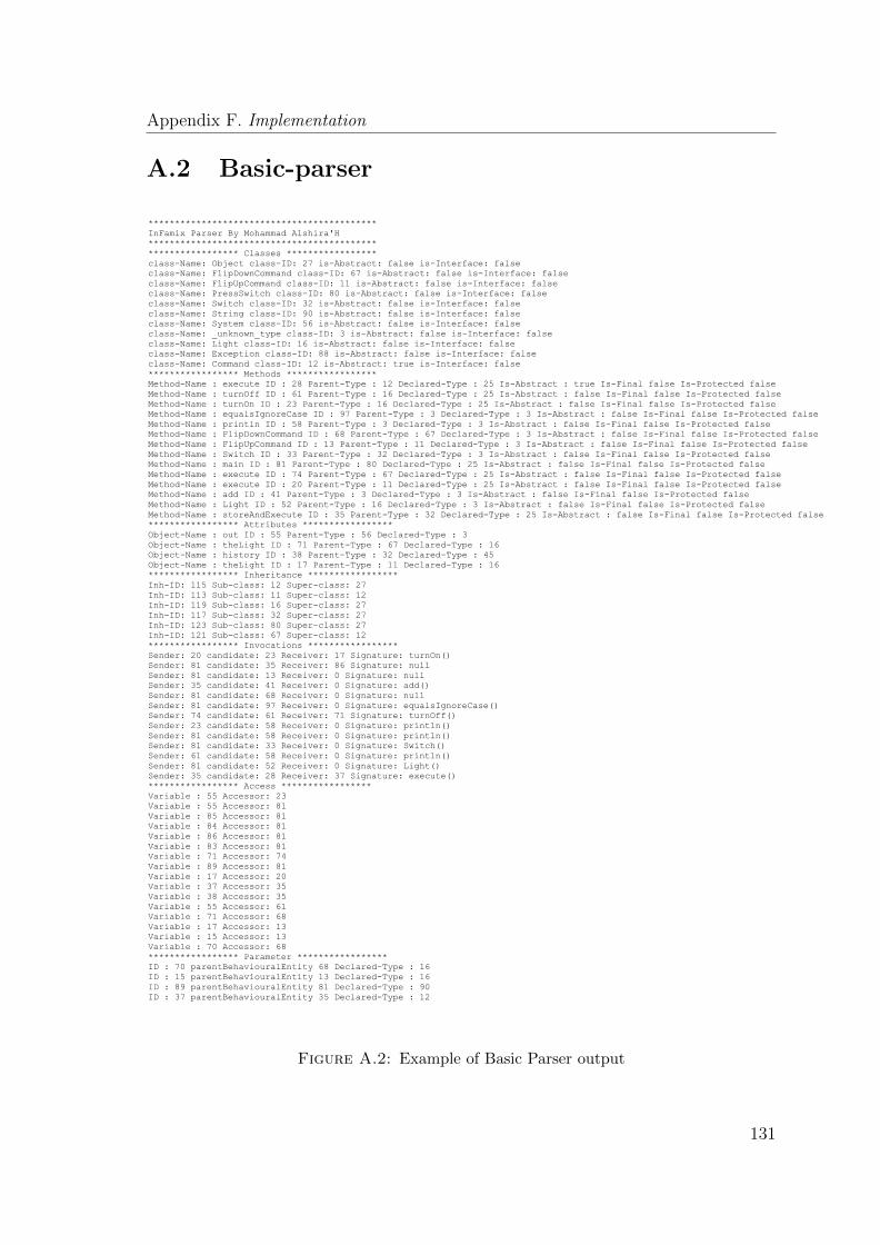
Appendix F. Implementation
A.2 Basic-parser
*******************************************
InFamix Parser By Mohammad Alshira'H
*******************************************
***************** Classes *****************
class-Name: Object class-ID: 27 is-Abstract: false is-Interface: false
class-Name: FlipDownCommand class-ID: 67 is-Abstract: false is-Interface: false
class-Name: FlipUpCommand class-ID: 11 is-Abstract: false is-Interface: false
class-Name: PressSwitch class-ID: 80 is-Abstract: false is-Interface: false
class-Name: Switch class-ID: 32 is-Abstract: false is-Interface: false
class-Name: String class-ID: 90 is-Abstract: false is-Interface: false
class-Name: System class-ID: 56 is-Abstract: false is-Interface: false
class-Name: _unknown_type class-ID: 3 is-Abstract: false is-Interface: false
class-Name: Light class-ID: 16 is-Abstract: false is-Interface: false
class-Name: Exception class-ID: 88 is-Abstract: false is-Interface: false
class-Name: Command class-ID: 12 is-Abstract: true is-Interface: false
***************** Methods *****************
Method-Name : execute ID : 28 Parent-Type : 12 Declared-Type : 25 Is-Abstract : true Is-Final false Is-Protected false
Method-Name : turnOff ID : 61 Parent-Type : 16 Declared-Type : 25 Is-Abstract : false Is-Final false Is-Protected false
Method-Name : turnOn ID : 23 Parent-Type : 16 Declared-Type : 25 Is-Abstract : false Is-Final false Is-Protected false
Method-Name : equalsIgnoreCase ID : 97 Parent-Type : 3 Declared-Type : 3 Is-Abstract : false Is-Final false Is-Protected false
Method-Name : println ID : 58 Parent-Type : 3 Declared-Type : 3 Is-Abstract : false Is-Final false Is-Protected false
Method-Name : FlipDownCommand ID : 68 Parent-Type : 67 Declared-Type : 3 Is-Abstract : false Is-Final false Is-Protected false
Method-Name : FlipUpCommand ID : 13 Parent-Type : 11 Declared-Type : 3 Is-Abstract : false Is-Final false Is-Protected false
Method-Name : Switch ID : 33 Parent-Type : 32 Declared-Type : 3 Is-Abstract : false Is-Final false Is-Protected false
Method-Name : main ID : 81 Parent-Type : 80 Declared-Type : 25 Is-Abstract : false Is-Final false Is-Protected false
Method-Name : execute ID : 74 Parent-Type : 67 Declared-Type : 25 Is-Abstract : false Is-Final false Is-Protected false
Method-Name : execute ID : 20 Parent-Type : 11 Declared-Type : 25 Is-Abstract : false Is-Final false Is-Protected false
Method-Name : add ID : 41 Parent-Type : 3 Declared-Type : 3 Is-Abstract : false Is-Final false Is-Protected false
Method-Name : Light ID : 52 Parent-Type : 16 Declared-Type : 3 Is-Abstract : false Is-Final false Is-Protected false
Method-Name : storeAndExecute ID : 35 Parent-Type : 32 Declared-Type : 25 Is-Abstract : false Is-Final false Is-Protected false
***************** Attributes *****************
Object-Name : out ID : 55 Parent-Type : 56 Declared-Type : 3
Object-Name : theLight ID : 71 Parent-Type : 67 Declared-Type : 16
Object-Name : history ID : 38 Parent-Type : 32 Declared-Type : 45
Object-Name : theLight ID : 17 Parent-Type : 11 Declared-Type : 16
***************** Inheritance *****************
Inh-ID: 115 Sub-class: 12 Super-class: 27
Inh-ID: 113 Sub-class: 11 Super-class: 12
Inh-ID: 119 Sub-class: 16 Super-class: 27
Inh-ID: 117 Sub-class: 32 Super-class: 27
Inh-ID: 123 Sub-class: 80 Super-class: 27
Inh-ID: 121 Sub-class: 67 Super-class: 12
***************** Invocations *****************
Sender: 20 candidate: 23 Receiver: 17 Signature: turnOn()
Sender: 81 candidate: 35 Receiver: 86 Signature: null
Sender: 81 candidate: 13 Receiver: 0 Signature: null
Sender: 35 candidate: 41 Receiver: 0 Signature: add()
Sender: 81 candidate: 68 Receiver: 0 Signature: null
Sender: 81 candidate: 97 Receiver: 0 Signature: equalsIgnoreCase()
Sender: 74 candidate: 61 Receiver: 71 Signature: turnOff()
Sender: 23 candidate: 58 Receiver: 0 Signature: println()
Sender: 81 candidate: 58 Receiver: 0 Signature: println()
Sender: 81 candidate: 33 Receiver: 0 Signature: Switch()
Sender: 61 candidate: 58 Receiver: 0 Signature: println()
Sender: 81 candidate: 52 Receiver: 0 Signature: Light()
Sender: 35 candidate: 28 Receiver: 37 Signature: execute()
***************** Access *****************
Variable : 55 Accessor: 23
Variable : 55 Accessor: 81
Variable : 85 Accessor: 81
Variable : 84 Accessor: 81
Variable : 86 Accessor: 81
Variable : 83 Accessor: 81
Variable : 71 Accessor: 74
Variable : 89 Accessor: 81
Variable : 17 Accessor: 20
Variable : 37 Accessor: 35
Variable : 38 Accessor: 35
Variable : 55 Accessor: 61
Variable : 71 Accessor: 68
Variable : 17 Accessor: 13
Variable : 15 Accessor: 13
Variable : 70 Accessor: 68
***************** Parameter *****************
ID : 70 parentBehaviouralEntity 68 Declared-Type : 16
ID : 15 parentBehaviouralEntity 13 Declared-Type : 16
ID : 89 parentBehaviouralEntity 81 Declared-Type : 90
ID : 37 parentBehaviouralEntity 35 Declared-Type : 12
Figure A.2: Example of Basic Parser output
131
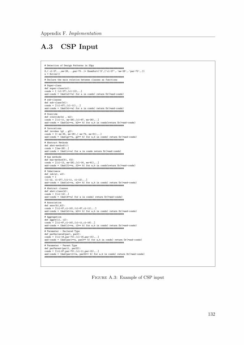
Appendix F. Implementation
A.3 CSP Input
# Detection of Design Patterns in Z3py
#############################################################
S,( cl-27,..,me-28,..,par-70..)= EnumSort(’S’,[’cl-27’,.’me-28’,.’par-70’,.])
s = Solver()
#############################################################
# Declare the main relation between classes as functions
#############################################################
# Super-class
def super-class(n1):
conds = [ (cl-27),(cl-12),..]
and-conds = (And(n1==a) for a in conds) return Or(*and-conds)
#############################################################
# sub-classes
def sub-class(b1):
conds = [(cl-67),(cl-11),..]
and-conds = (And(b1==a) for a in conds) return Or(*and-conds)
#############################################################
# Override
def override(h1 , h2):
conds = [(cl-11, me-28),(cl-67, me-28),..]
and-conds = (And(h1==a, h2== b) for a,b in conds)return Or(*and-conds)
#############################################################
# Invocations
def invokes (g1 , g2):
conds = [( me-35, me-28),( me-74, me-61),..]
and-conds = (And(g1==a, g2== b) for a,b in conds) return Or(*and-conds)
#############################################################
# Abstract Methods
def abst-method(c):
conds = [(me-28)..]
and-conds = (And(c==a) for a in conds return Or(*and-conds)
#############################################################
# has methods
def has-method(f1, f2):
conds = [(cl-12, me-28),(cl-16, me-61),..]
and-conds = (And(f1==a, f2== b) for a,b in conds)return Or(*and-conds)
#############################################################
# Inheitance
def inh(e1, e2):
conds = [
(cl-12, cl-27),(cl-11, cl-12),..]
and-conds = (And(e1==a, e2== b) for a,b in conds) return Or(*and-conds)
#############################################################
# Abstract classes
def abst-class(d):
conds = [(cl-12)..]
and-conds = (And(d==a) for a in conds) return Or(*and-conds)
#############################################################
# Assosiation
def asso(k1,k2):
conds = [(cl-67,cl-16),(cl-67,cl-11),..]
and-conds = (And(k1==a, k2== b) for a,b in conds) return Or(*and-conds)
#############################################################
# Aggregation
def aggre(i1, i2):
conds = [(cl-67,cl-16),(cl-11,cl-16)..]
and-conds = (And(i1==a, i2== b) for a,b in conds) return Or(*and-conds)
#############################################################
# Parameter - Declared Type
def parDeclared(par1, par2):
conds = [(cl-16,par-70),(cl-16,par-15),..]
and-conds = (And(par1==a, par2== b) for a,b in conds) return Or(*and-conds)
#############################################################
# Parameter - Parent Type
def parParent(par11, par22):
conds = [(cl-67,par-70),(cl-11,par-15),..]
and-conds = (And(par11==a, par22== b) for a,b in conds) return Or(*and-conds)
#############################################################
Figure A.3: Example of CSP input
132
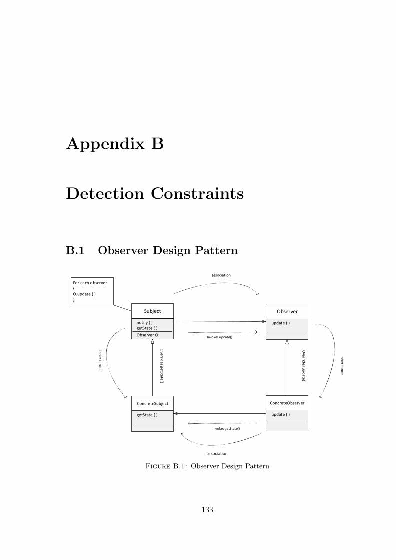
Appendix B
Detection Constraints
B.1 Observer Design Pattern
Observer
update ( )
Subject
getState ( )
Observer O
notify ( )
ConcreteObserver
update ( )
ConcreteSubject
getState ( )
association
association
inheritance
inheritance
Overrid
es update()
Overrid
es getState()
Invokes update()
Invokes getState()
For each observer{O.update ( )}
Figure B.1: Observer Design Pattern
133
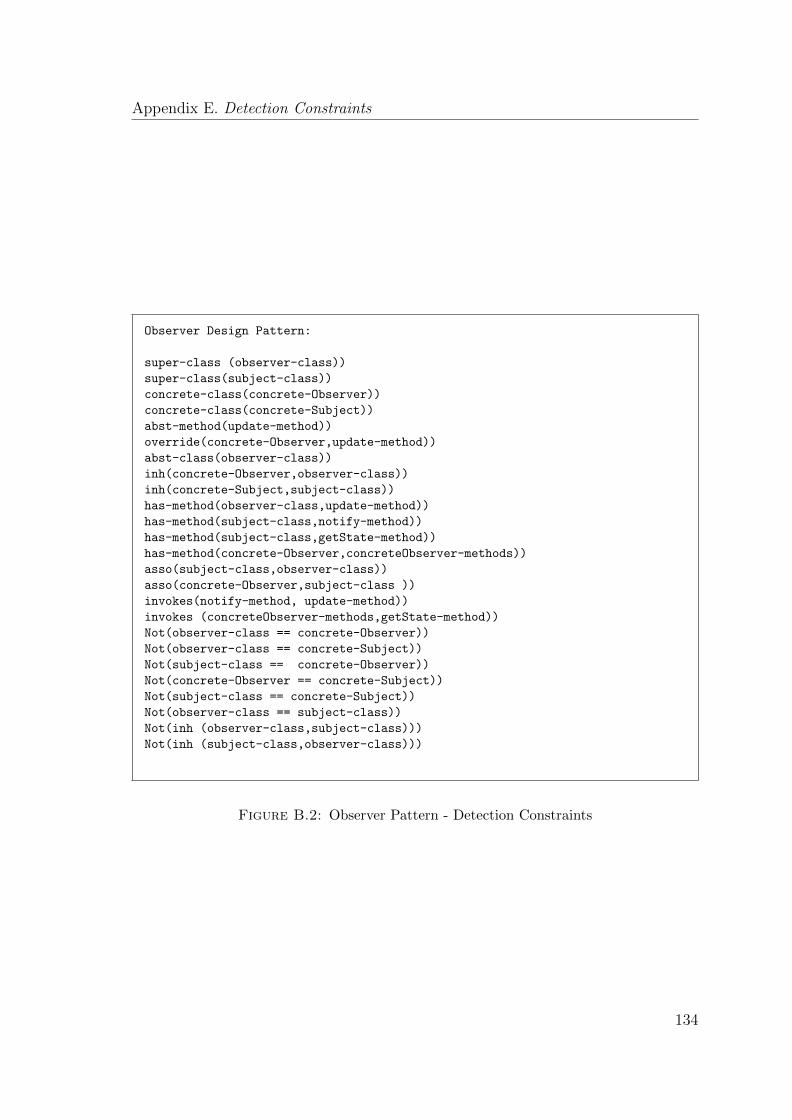
Appendix E. Detection Constraints
Observer Design Pattern:
super-class (observer-class))
super-class(subject-class))
concrete-class(concrete-Observer))
concrete-class(concrete-Subject))
abst-method(update-method))
override(concrete-Observer,update-method))
abst-class(observer-class))
inh(concrete-Observer,observer-class))
inh(concrete-Subject,subject-class))
has-method(observer-class,update-method))
has-method(subject-class,notify-method))
has-method(subject-class,getState-method))
has-method(concrete-Observer,concreteObserver-methods))
asso(subject-class,observer-class))
asso(concrete-Observer,subject-class ))
invokes(notify-method, update-method))
invokes (concreteObserver-methods,getState-method))
Not(observer-class == concrete-Observer))
Not(observer-class == concrete-Subject))
Not(subject-class == concrete-Observer))
Not(concrete-Observer == concrete-Subject))
Not(subject-class == concrete-Subject))
Not(observer-class == subject-class))
Not(inh (observer-class,subject-class)))
Not(inh (subject-class,observer-class)))
Figure B.2: Observer Pattern - Detection Constraints
134

Appendix E. Detection Constraints
B.2 State/Strategy Design Pattern
State/Strategy
abstMethod
Context
ConcreteState/Strategy
abstMethod
aggregationinheritance
Overrid
es abstM
ethod
()
Figure B.3: State/Strategy Design Pattern
State/Strategy Design Pattern:
super-class(state-strategy-role))
inh(concrete-class-role,state-strategy-role))
aggre(context-class-role,state-strategy-role))
has-method(state-strategy-role,abstr-method))
abst-method(abstr-method))
override(concrete-class-role,abstr-method))
Not(state-strategy-role == context-class-role))
Figure B.4: State/Strategy Pattern - Detection Constraints
135
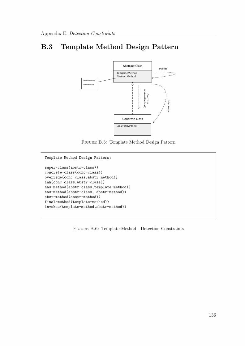
Appendix E. Detection Constraints
B.3 Template Method Design Pattern
Abstract Class
TemplateMethodAbstractMethod
Concrete Class
AbstratcMethod
inh
eritance
Overrid
es A
bstractM
ethod
()
invokes
TemplateMethod{AbstractMethod}
Figure B.5: Template Method Design Pattern
Template Method Design Pattern:
super-class(abstr-class))
concrete-class(conc-class))
override(conc-class,abstr-method))
inh(conc-class,abstr-class))
has-method(abstr-class,template-method))
has-method(abstr-class, abstr-method))
abst-method(abstr-method))
final-method(template-method))
invokes(template-method,abstr-method))
Figure B.6: Template Method - Detection Constraints
136
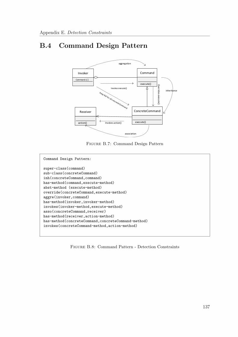
Appendix E. Detection Constraints
B.4 Command Design Pattern
Invoker
Command c[ ]
Command
execute()
Receiver
action()
ConcreteCommand
execute()
aggregation
inheritance
association
Overrid
es execute()
Invokes execute()
Invokes action()
Figure B.7: Command Design Pattern
Command Design Pattern:
super-class(command)
sub-class(concreteCommand)
inh(concreteCommand,command)
has-method(command,execute-method)
abst-method (execute-method)
override(concreteCommand,execute-method)
aggre(invoker,command)
has-method(invoker,invoker-method)
invokes(invoker-method,execute-method)
asso(concreteCommand,receiver)
has-method(receiver,action-method)
has-method(concreteCommand,concreteCommand-method)
invokes(concreteCommand-method,action-method)
Figure B.8: Command Pattern - Detection Constraints
137

Appendix C
Hint Templates
C.1 Structural Hints
138
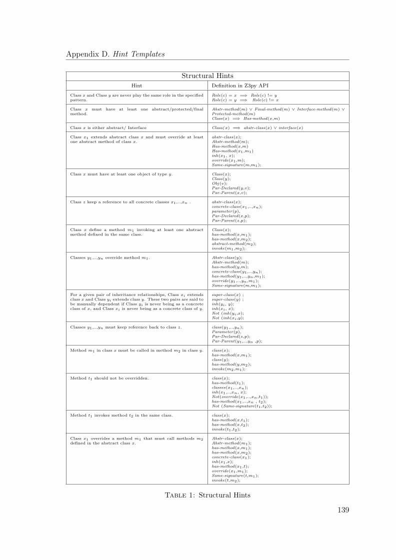
Appendix D. Hint Templates
Structural Hints
Hint Definition in Z3py API
Class x and Class y are never play the same role in the specifiedpattern.
Role(c) = x =⇒ Role(c) != yRole(c) = y =⇒ Role(c) != x
Class x must have at least one abstract/protected/finalmethod.
Abstr-method(m) ∨ Final-method(m) ∨ Interface-method(m) ∨Protected-method(m)Class(x) =⇒ Has-method(x,m)
Class x is either abstract/ Interface Class(x) =⇒ abstr-class(x) ∨ interface(x)
Class x1 extends abstract class x and must override at leastone abstract method of class x.
abstr-class(x);Abstr-method(m);Has-method(x,m)Has-method(x1,m1)inh(x1, x);override(x1,m);Same-signature(m,m1);
Class x must have at least one object of type y. Class(x);Class(y);Obj(v);Par-Declared(y,v);Par-Parent(x,v);
Class z keep a reference to all concrete classes x1,..,xn . abstr-class(x);concrete-class(x1,..,xn);parameter(p),Par-Declared(x,p);Par-Parent(z,p);
Class x define a method m1 invoking at least one abstractmethod defined in the same class.
Class(x);has-method(x,m1);has-method(x,m2);abstract-method(m2);invoke(m1,m2);
Classes y1,..,yn override method m1. Abstr-class(y);Abstr-method(m);has-method(y,m);concrete-class(y1,..,yn);has-method(y1,..,yn,m1);override(y1,..,yn,m1);Same-signature(m,m1);
For a given pair of inheritance relationships, Class xi extendsclass x and Class yi extends class y. These two pairs are said tobe manually dependent if Class yi is never being as a concreteclass of x, and Class xi is never being as a concrete class of y.
super-class(x) ;super-class(y) ;inh(yi, y);inh(xi, x);Not (inh(yi,x);Not (inh(xi,y);
Classes y1,..,yn must keep reference back to class z. class(y1,..,yn);Parameter(p),Par-Declared(z,p);Par-Parent(y1,..,yn ,p);
Method m1 in class x must be called in method m2 in class y. class(x);has-method(x,m1);class(y);has-method(y,m2);invoke(m2,m1);
Method t1 should not be overridden. class(x);has-method(t1);classes(x1,..,xn);inh(x1,..,xn, x);Not(override(x1,..,xn,t1));has-method(x1,..,xn , t2);Not (Same-signature(t1,t2));
Method t1 invokes method t2 in the same class. class(x);has-method(x,t1);has-method(x,t2);invoke(t1,t2);
Class x1 overrides a method m1 that must call methods m2defined in the abstract class x.
Abstr-class(x);Abstr-method(m1);has-method(x,m1);has-method(x,m2);concrete-class(x1);inh(x1,x);has-method(x1,t);override(x1,m1);Same-signature(t,m1);invoke(t,m2);
Table 1: Structural Hints
139
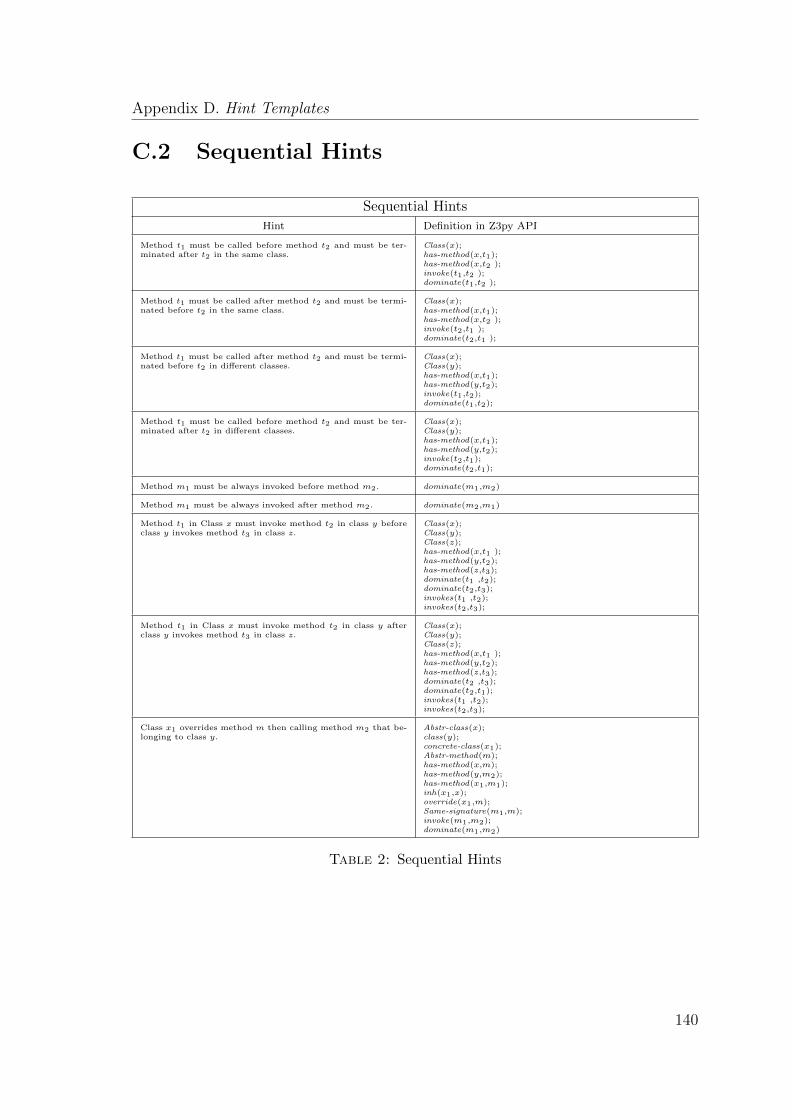
Appendix D. Hint Templates
C.2 Sequential Hints
Sequential Hints
Hint Definition in Z3py API
Method t1 must be called before method t2 and must be ter-minated after t2 in the same class.
Class(x);has-method(x,t1);has-method(x,t2 );invoke(t1,t2 );dominate(t1,t2 );
Method t1 must be called after method t2 and must be termi-nated before t2 in the same class.
Class(x);has-method(x,t1);has-method(x,t2 );invoke(t2,t1 );dominate(t2,t1 );
Method t1 must be called after method t2 and must be termi-nated before t2 in different classes.
Class(x);Class(y);has-method(x,t1);has-method(y,t2);invoke(t1,t2);dominate(t1,t2);
Method t1 must be called before method t2 and must be ter-minated after t2 in different classes.
Class(x);Class(y);has-method(x,t1);has-method(y,t2);invoke(t2,t1);dominate(t2,t1);
Method m1 must be always invoked before method m2. dominate(m1,m2)
Method m1 must be always invoked after method m2. dominate(m2,m1)
Method t1 in Class x must invoke method t2 in class y beforeclass y invokes method t3 in class z.
Class(x);Class(y);Class(z);has-method(x,t1 );has-method(y,t2);has-method(z,t3);dominate(t1 ,t2);dominate(t2,t3);invokes(t1 ,t2);invokes(t2,t3);
Method t1 in Class x must invoke method t2 in class y afterclass y invokes method t3 in class z.
Class(x);Class(y);Class(z);has-method(x,t1 );has-method(y,t2);has-method(z,t3);dominate(t2 ,t3);dominate(t2,t1);invokes(t1 ,t2);invokes(t2,t3);
Class x1 overrides method m then calling method m2 that be-longing to class y.
Abstr-class(x);class(y);concrete-class(x1);Abstr-method(m);has-method(x,m);has-method(y,m2);has-method(x1,m1);inh(x1,x);override(x1,m);Same-signature(m1,m);invoke(m1,m2);dominate(m1,m2)
Table 2: Sequential Hints
140

Appendix D
Survey Request and Questionnaire
Form
D.1 Survey Request Letter
Dear Members,
We are conducting a survey on: Design Pattern Detection and User Knowledge as part of a research study that
investigates expert users with GoF design patterns. The purpose of this survey is to study how an expert user
can supply useful hints to assist the design pattern detection process.
I’ve invited you to fill out a form of a questionnaire. Kindly complete this questionnaire and at the end of
each part, feel free to write your valuable comments on any problem or difficulty you found in answering
the questions. This questionnaire will take approximately 20-25 minutes to complete. I really appreciate, in
advance, your generosity of sharing your experiences, your time, and cooperation.
To access the questionnaire, please visit: https://www.surveymonkey.com/s/65FBCWP.
Please feel free to forward this link to anyone you think may be able to help.
Kind Regards,
Researcher
141

Appendix A. Questionnaire Form
D.2 Questionnaire Form
D.2.1 Introduction
Survey on Design Pattern Detection and User Knowledge
Thank you for participating in our survey.
As part of a research study, we are investigating expert users with GoF design
patterns.
The purpose of this survey is to investigate how an expert user can supply useful
hints in the design pattern detection process.
We begin by asking about your experiences with using design patterns. We then
ask you to provide us with a little information about three selected scenarios.
We really appreciate your generosity of sharing your experiences and perspectives
about design patterns.
This survey will take approximately 20 to 25 minutes to complete.
142

Appendix A. Questionnaire Form
D.2.2 Demographic
1. Contact Information:
• Name: ..........................................
• Email address: .............................
2. How do you rate your experience with design patterns?
• Beginner
• Good
• Expert
3. What is your job role?
• Software Developer
• Researcher
• Student
• Other (please specify)
143
Appendix A. Questionnaire Form
D.2.3 Selected Scenario
In this section you are asked to provide us with your assessment of the usefulness of
some facts that support our suspicion of pattern instances in the source code. Based
upon your experiences with using design patterns, please rate each fact as:
Very Negative
Negative
Not Significant
Positive
Very Positive
D.2.3.1 Scenario 1
We know the following:
JHotDraw provides menu items, which allow the user to tell the program what action
to perform. Each choice in a menu bar is an instance of a CommandMenu class.
This class provides a method execute(), which is an abstraction provided as a very
simple entry point for the external classes (Clients) to use the concrete commands
without knowing unnecessary details about them.
CommandButton class works as a command enabled button where the client selects
a menu item by clicking the button to execute the command, it causes an action-
Performed event. The method gets a selected menu item and the corresponding
Command (CutCommand, copyCommand).
We suspect that the above characterises the behaviour of the Command
pattern, consider the following facts and rate them according to the ex-
tent by which they support our suspicion.
144
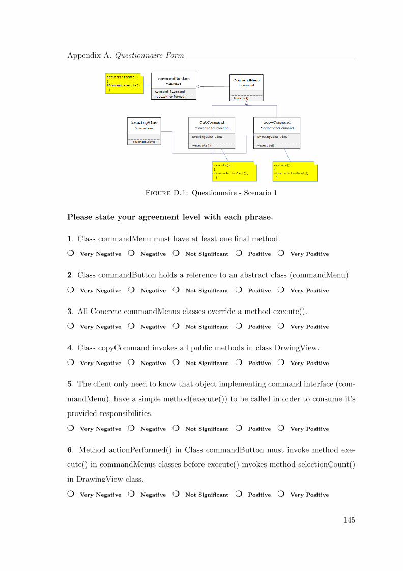
Appendix A. Questionnaire Form
Figure D.1: Questionnaire - Scenario 1
Please state your agreement level with each phrase.
1. Class commandMenu must have at least one final method.
m Very Negative m Negative m Not Significant m Positive m Very Positive
2. Class commandButton holds a reference to an abstract class (commandMenu)
m Very Negative m Negative m Not Significant m Positive m Very Positive
3. All Concrete commandMenus classes override a method execute().
m Very Negative m Negative m Not Significant m Positive m Very Positive
4. Class copyCommand invokes all public methods in class DrwingView.
m Very Negative m Negative m Not Significant m Positive m Very Positive
5. The client only need to know that object implementing command interface (com-
mandMenu), have a simple method(execute()) to be called in order to consume it’s
provided responsibilities.
m Very Negative m Negative m Not Significant m Positive m Very Positive
6. Method actionPerformed() in Class commandButton must invoke method exe-
cute() in commandMenus classes before execute() invokes method selectionCount()
in DrawingView class.
m Very Negative m Negative m Not Significant m Positive m Very Positive
145
Appendix A. Questionnaire Form
7. Method actionPerformed() in Class commandButton invokes an abstract method
in the same class.
m Very Negative m Negative m Not Significant m Positive m Very Positive
8. All Concrete classes commandMenus override all the abstract methods of class
commandMenu.
m Very Negative m Negative m Not Significant m Positive m Very Positive
D.2.3.2 Scenario 2
We know the following:
In JUnit, the class TestCase defines the fixture to run multiple tests. It contains one
or more tests, and groups together the tests that exercise the common behaviours.
This class provides a method run() calling setUp() followed by runTest() and tear-
Down(). TestCase is declared abstract and follows a very specific sequence of events
when invoking the tests. The execution of this sequence, however, will remain the
same for all tests, no matter how the fixture code is written or how the testing code
is written. First, it constructs a new instance of the test case for each test method.
After constructing all of the test case objects, JUnit follows these steps for each test
method:
• Call the test cases setUp() method.
• Call the runTest() method.
• Call the test cases tearDown() method.
These three methods contain a default implementation for each test, and they are
intended to be overridden in the subclasses, so they were declared as protected
methods.
146

Appendix A. Questionnaire Form
We suspect that the above is an instance of the Template Method pat-
tern. Consider the following facts and rate them according to the extent
by which they support our suspicion.
Figure D.2: Questionnaire - Scenario 2
Please state your agreement level with each phrase.
1. Class TestCase specifies a method that invoking at least one abstract/protected
method defined in the same class.
m Very Negative m Negative m Not Significant m Positive m Very Positive
2. Class TestCase must have at least one public/final method, and this method
should not be overridden in the concrete classes.
m Very Negative m Negative m Not Significant m Positive m Very Positive
3. The class TestCase must be declared abstract.
m Very Negative m Negative m Not Significant m Positive m Very Positive
4. Method run() in TestCase class invokes method setUp() followed by runTest()
and tearDown() in the same class.
m Very Negative m Negative m Not Significant m Positive m Very Positive
5. All Concrete classes of TestCase should override all inherited abstract/protected
methods.
m Very Negative m Negative m Not Significant m Positive m Very Positive
6. All Concrete classes of TestCase class override at least one of the following
methods. setUp(), runTest() and tearDown().
m Very Negative m Negative m Not Significant m Positive m Very Positive
147
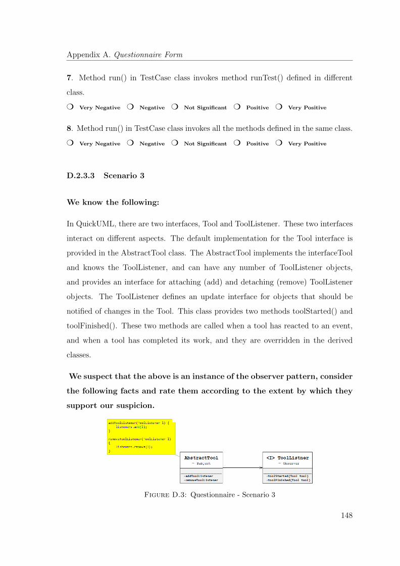
Appendix A. Questionnaire Form
7. Method run() in TestCase class invokes method runTest() defined in different
class.
m Very Negative m Negative m Not Significant m Positive m Very Positive
8. Method run() in TestCase class invokes all the methods defined in the same class.
m Very Negative m Negative m Not Significant m Positive m Very Positive
D.2.3.3 Scenario 3
We know the following:
In QuickUML, there are two interfaces, Tool and ToolListener. These two interfaces
interact on different aspects. The default implementation for the Tool interface is
provided in the AbstractTool class. The AbstractTool implements the interfaceTool
and knows the ToolListener, and can have any number of ToolListener objects,
and provides an interface for attaching (add) and detaching (remove) ToolListener
objects. The ToolListener defines an update interface for objects that should be
notified of changes in the Tool. This class provides two methods toolStarted() and
toolFinished(). These two methods are called when a tool has reacted to an event,
and when a tool has completed its work, and they are overridden in the derived
classes.
We suspect that the above is an instance of the observer pattern, consider
the following facts and rate them according to the extent by which they
support our suspicion.
Figure D.3: Questionnaire - Scenario 3
148

Appendix A. Questionnaire Form
Please state your agreement level with each phrase.
1. Method addToollistner() in the AbstractTool must call all the abstract methods
in the AbstractTool class.
m Very Negative m Negative m Not Significant m Positive m Very Positive
2. Class AbstractTool must have at least one object of type ToolListener.
m Very Negative m Negative m Not Significant m Positive m Very Positive
3. Class AbstractTool invokes all the public methods in the ToolListener class.
m Very Negative m Negative m Not Significant m Positive m Very Positive
4. All concrete observers (subclasses of ToolListener) must override at least one
method belonging to its super class.
m Very Negative m Negative m Not Significant m Positive m Very Positive
5. Method toolStarted() should invokes an abstract method in the same class.
m Very Negative m Negative m Not Significant m Positive m Very Positive
6. Method in class AbstractTool class invokes method toolStarted () and toolFin-
ished in ToolListener class.
m Very Negative m Negative m Not Significant m Positive m Very Positive
7. All concrete observers (subclasses of ToolListener) should override all inherited
abstract methods.
m Very Negative m Negative m Not Significant m Positive m Very Positive
8. All concrete observers (subclasses of ToolListener) override toolStarted() and/or
toolFinished() that belonging to the ToolListener class.
m Very Negative m Negative m Not Significant m Positive m Very Positive
149
Bibliography
[1] Eclipse ide. http://www.eclipse.org/.
[2] Jhotdraw. http://www.jhotdraw.org.
[3] Junit. http://junit.org.
[4] Ptidej. http://www.ptidej.net/.
[5] Quickuml. http://sourceforge.net/projects/quj/.
[6] Aho, A., Sethi, R., and Ullman, J. (1986). Compilers: Principles, Techniques,
and Tools. Addison-Wesley.
[7] Albin-Amiot, H., Cointe, P., Gueheneuc, Y.-G., and Jussien, N. (2001). In-
stantiating and detecting design patterns: Putting bits and pieces together. In
Automated Software Engineering, 2001.(ASE 2001). Proceedings. 16th Annual In-
ternational Conference on, pages 166–173. IEEE.
[8] Albin-amiot, H., Gueheneuc, Y.-g., and Kastler, R. A. (2001). Meta-modeling de-
sign patterns: Application to pattern detection and code synthesis. In Proc. First
ECOOP Workshop Automating Object-Oriented Software Development Methods.
Citeseer.
[9] Alexander, C., Ishikawa, S., and Silverstein, M. (1977). A pattern language:
towns, buildings, construction, volume 2. Oxford University Press.
150
Bibliography
[10] Alnusair, A., Zhao, T., and Yan, G. (2014). Rule-based detection of design
patterns in program code. International Journal on Software Tools for Technology
Transfer, 16(3):315–334.
[11] Anderson, B. (1992). Towards an architecture handbook. SIGPLAN OOPS
Mess., 4(2):109–113.
[12] Angluin, D. (1987). Learning regular sets from queries and counterexamples.
Information and computation, 75(2):87–106.
[13] Antoniol, G., Fiutem, R., and Cristoforetti, L. (1998). Design pattern recovery
in object-oriented software. In Program Comprehension, 1998. IWPC’98. Pro-
ceedings., 6th International Workshop on, pages 153–160. IEEE.
[14] Arcelli, F., Masiero, S., Raibulet, C., and Tisato, F. (2005). A comparison of
reverse engineering tools based on design pattern decomposition. In Software En-
gineering Conference, 2005. Proceedings. 2005 Australian, pages 262–269. IEEE.
[15] Aversano, L., Canfora, G., Cerulo, L., Del Grosso, C., and Di Penta, M. (2007).
An empirical study on the evolution of design patterns. In Proceedings of the the
6th joint meeting of the European software engineering conference and the ACM
SIGSOFT symposium on The foundations of software engineering, pages 385–394.
ACM.
[16] Balanyi, Z. and Ferenc, R. (2003). Mining design patterns from c++ source
code. In Software Maintenance, 2003. ICSM 2003. Proceedings. International
Conference on, pages 305–314. IEEE.
[17] Bansiya, J. (1998). Automating design-pattern identification. Dr. Dobb’s jour-
nal, 23(6).
[18] Basili, V. R., Selby, R. W., and Hutchens, D. H. (1986). Experimentation in
software engineering. Software Engineering, IEEE Transactions on, (7):733–743.
151
Bibliography
[19] Bayley, I. and Zhu, H. (2010). Formal specification of the variants and be-
havioural features of design patterns. Journal of Systems and Software, 83(2):209–
221.
[20] Beck, K. and Cunningham, W. (1987). Using Pattern Languages for Object-
Oriented Programs. Technical report.
[21] Bellay, B. and Gall, H. (1997). A comparison of four reverse engineering tools.
In Reverse Engineering, 1997. Proceedings of the Fourth Working Conference on,
pages 2–11. IEEE.
[22] Bessiere, C., Coletta, R., O’Sullivan, B., and Paulin, M. (2007). Query-driven
constraint acquisition. pages 50–55.
[23] Bieman, J. M., Straw, G., Wang, H., Munger, P. W., and Alexander, R. T.
(2003). Design patterns and change proneness: An examination of five evolving
systems. In Software metrics symposium, 2003. Proceedings. Ninth international,
pages 40–49. IEEE.
[24] Binun, A. and Kniesel, G. (2012). Dpjf-design pattern detection with high accu-
racy. In Software Maintenance and Reengineering (CSMR), 2012 16th European
Conference on, pages 245–254. IEEE.
[25] Boone, H. N. and Boone, D. A. (2012). Analyzing likert data. Journal of
Extension, 50(2):1–5.
[26] Boujarwah, A. S., Saleh, K., and Al-Dallal, J. (2000). Dynamic data flow
analysis for java programs. Information and Software Technology, 42(11):765–
775.
[27] Buschmann, F., Meunier, R., Rohnert, H., Sommerlad, P., and Stal, M. (1996).
Pattern-oriented Software Architecture: A System of Patterns. John Wiley &
Sons, Inc., New York, NY, USA.
152
Bibliography
[28] Chatzigeorgiou, A., Tsantalis, N., and Deligiannis, I. (2008). An empirical
study on students ability to comprehend design patterns. Computers & Education,
51(3):1007–1016.
[29] Chikofsky, E. J., Cross, J. H., et al. (1990). Reverse engineering and design
recovery: A taxonomy. Software, IEEE, 7(1):13–17.
[30] Coplien, J. O. (1991). Advanced C++ Programming Styles and Idioms.
Addison-Wesley Longman Publishing Co., Inc., Boston, MA, USA.
[31] Cornelissen, B., Zaidman, A., Van Deursen, A., Moonen, L., and Koschke, R.
(2009). A systematic survey of program comprehension through dynamic analysis.
Software Engineering, IEEE Transactions on, 35(5):684–702.
[32] Corp., I. (Released 2013). Ibm spss statistics for windows, version 22.0.
[33] De Lucia, A., Deufemia, V., Gravino, C., and Risi, M. (2009). Behavioral pat-
tern identification through visual language parsing and code instrumentation. In
Software Maintenance and Reengineering, 2009. CSMR’09. 13th European Con-
ference on, pages 99–108. IEEE.
[34] De Lucia, A., Deufemia, V., Gravino, C., and Risi, M. (2010a). An eclipse
plug-in for the detection of design pattern instances through static and dynamic
analysis. In Software Maintenance (ICSM), 2010 IEEE International Conference
on, pages 1–6. IEEE.
[35] De Lucia, A., Deufemia, V., Gravino, C., and Risi, M. (2010b). Improving
behavioral design pattern detection through model checking. In Software Main-
tenance and Reengineering (CSMR), 2010 14th European Conference on, pages
176–185. IEEE.
[36] De Moura, L. and Bjørner, N. (2008). Z3: An efficient smt solver. In Tools
and Algorithms for the Construction and Analysis of Systems, pages 337–340.
Springer.
153

Bibliography
[37] Demeyer, S., Tichelaar, S., and Ducasse, S. (2001). Famix 2.1 the famoos
information exchange model.
[38] Denier, S., Khomh, F., Gueheneuc, Y.-G., and Team, P. (2008). Reverse-
engineering the Literature on Design Patterns and Reverse-engineering.
[39] Dong, J., Lad, D. S., and Zhao, Y. (2007a). Dp-miner: Design pattern discovery
using matrix. In Engineering of Computer-Based Systems, 2007. ECBS’07. 14th
Annual IEEE International Conference and Workshops on the, pages 371–380.
IEEE.
[40] Dong, J., Peng, T., and Qiu, Z. (2007b). Commutability of design pattern
instantiation and integration. In Theoretical Aspects of Software Engineering,
2007. TASE’07. First Joint IEEE/IFIP Symposium on, pages 283–292. IEEE.
[41] Dong, J., Zhao, Y., and Sun, Y. (2009). A matrix-based approach to recovering
design patterns. Systems, Man and Cybernetics, Part A: Systems and Humans,
IEEE Transactions on, 39(6):1271–1282.
[42] Ducasse, S., Anquetil, N., Bhatti, M. U., Hora, A. C., Laval, J., and Girba,
T. (2011). Mse and famix 3.0: an interexchange format and source code model
family.
[43] Dwyer, M., Avrunin, G., and Corbett, J. (1999). Patterns in property specifi-
cations for finite-state verification. In ICSE, pages 411–420.
[44] El-Boussaidi, G. and Mili, H. (2008). Detecting patterns of poor design solu-
tions using constraint propagation. In Model Driven Engineering Languages and
Systems, pages 189–203. Springer.
[45] Elaasar, M., Briand, L. C., and Labiche, Y. (2013). Vpml: an approach to
detect design patterns of mof-based modeling languages. Software & Systems
Modeling, pages 1–30.
154
Bibliography
[46] Ernst, M. D. (2003). Static and dynamic analysis: Synergy and duality. In
WODA 2003: ICSE Workshop on Dynamic Analysis, Portland, OR, pages 24–
27, New Mexico State University. Jonathan Cook.
[47] Ferenc, R., Beszedes, A., Fulop, L., and Lele, J. (2005). Design pattern min-
ing enhanced by machine learning. In Software Maintenance, 2005. ICSM’05.
Proceedings of the 21st IEEE International Conference on, pages 295–304. IEEE.
[48] Fink, A. (2003). The survey handbook, volume 1. Sage.
[49] Fontana, F. A., Zanoni, M., and Maggioni, S. (2011). Using design pattern
clues to improve the precision of design pattern detection tools. Journal of Object
Technology, 10(4):1–31.
[50] Freeman, E., Robson, E., Bates, B., and Sierra, K. (2004). Head first design
patterns. ” O’Reilly Media, Inc.”.
[51] Gamma, E. Junit: A cook’s tour. http://junit.sourceforge.net/doc/
cookstour/cookstour.htm.
[52] Gamma, E. (1991). Object-Oriented Software Development based on ET++.
PhD thesis, University of Zurich.
[53] Gamma, E., Helm, R., Johnson, R., and Vlissides, J. (1993). Design patterns:
Abstraction and reuse of object-oriented design. Springer.
[54] Gamma, E., Helm, R., Johnson, R., and Vlissides, J. (1995). Design Patterns:
Elements of Reusable Object-oriented Software. Addison-Wesley Longman Pub-
lishing Co., Inc., Boston, MA, USA.
[55] Gil, J. Y. and Maman, I. (2005). Micro patterns in java code. In ACM SIG-
PLAN Notices, volume 40, pages 97–116. ACM.
[56] Gravino, C., Risi, M., Scanniello, G., and Tortora, G. (2012). Do professional
developers benefit from design pattern documentation? a replication in the context
of source code comprehension. Springer.
155
Bibliography
[57] Gueheneuc, Y.-G. (2004). A reverse engineering tool for precise class diagrams.
In Proceedings of the 2004 conference of the Centre for Advanced Studies on Col-
laborative research, pages 28–41. IBM Press.
[58] Gueheneuc, Y.-G. (2005). Ptidej: Promoting patterns with patterns. Proceed-
ings of the 1st ECOOP workshop on Building a System using Patterns. Springer-
Verlag.
[59] Gueheneuc, Y.-G. (2007). P-mart: Pattern-like micro architecture repository.
Proceedings of the 1st EuroPLoP Focus Group on Pattern Repositories.
[60] Gueheneuc, Y.-G. and Antoniol, G. (2008). Demima: A multilayered approach
for design pattern identification. Software Engineering, IEEE Transactions on,
34(5):667–684.
[61] Gueheneuc, Y.-G., Guyomarch, J.-Y., and Sahraoui, H. (2010). Improving
design-pattern identification: a new approach and an exploratory study. Software
Quality Journal, 18(1):145–174.
[62] Gueheneuc, Y.-G. and Jussien, N. (2001). Using explanations for design-
patterns identification. In IJCAI, volume 1, pages 57–64. Citeseer.
[63] Gueheneuc, Y.-G., Khosravi, K., Sahraoui, H., et al. (2005). Design patterns
as laws of quality.
[64] Gueheneuc, Y.-G., Mens, K., Wuyts, R., et al. (2006). A comparative framework
for design recovery tools. In CSMR, volume 6, pages 123–134.
[65] Gueheneuc, Y.-G., Sahraoui, H., and Zaidi, F. (2004). Fingerprinting design
patterns. In Reverse Engineering, 2004. Proceedings. 11th Working Conference
on, pages 172–181. IEEE.
[66] Gueheneuc, Y.-G. and Ziadi, T. (2005). Automated reverse-engineering of uml
v2. 0 dynamic models. In proceedings of the 6th ECOOP Workshop on Object-
Oriented Reengineering. Citeseer.
156
Bibliography
[67] Hall, M., Walkinshaw, N., and McMinn, P. (2012). Supervised software modu-
larisation. pages 472–481.
[68] Hayashi, S., Katada, J., Sakamoto, R., Kobayashi, T., and Saeki, M. (2008).
Design pattern detection by using meta patterns. IEICE TRANSACTIONS on
Information and Systems, 91(4):933–944.
[69] Heuzeroth, D., Holl, T., Hogstrom, G., and Lowe, W. (2003). Automatic design
pattern detection. In Program Comprehension, 2003. 11th IEEE International
Workshop on, pages 94–103. IEEE.
[70] Johnson, C. (2011). Human error, interaction and the development of safety–
critical systems. In A.Boy, G., editor, The handbook of human-machine interaction
A Human-Centered Design approach. Ashgate, UK.
[71] Jussien, N. and Barichard, V. (2000). The palm system: explanation-based
constraint programming.
[72] Kaczor, O., Gueheneuc, Y.-G., and Hamel, S. (2006). Efficient identification of
design patterns with bit-vector algorithm. In Software Maintenance and Reengi-
neering, 2006. CSMR 2006. Proceedings of the 10th European Conference on,
pages 10–pp. IEEE.
[73] Kasunic, M. (2005). Designing an effective survey. Technical report, DTIC
Document.
[74] Keller, R. K., Schauer, R., Robitaille, S., and Page, P. (1999). Pattern-based
reverse-engineering of design components. In Proceedings of the 21st international
conference on Software engineering, pages 226–235. ACM.
[75] Khomh, F. and Gueheneuc, Y.-G. (2008). Do design patterns impact software
quality positively? In Software Maintenance and Reengineering, 2008. CSMR
2008. 12th European Conference on, pages 274–278. IEEE.
157

Bibliography
[76] Khomh, F., Gueheneuc, Y.-G., and Team, P. (2008). An empirical study of
design patterns and software quality. GEODES–Research Group on Open, Dis-
tributed Systems, Experimental Software Engineering, University of Montreal.
[77] Kirasic, D. and Basch, D. (2008). Ontology-based design pattern recognition.
In Knowledge-Based Intelligent Information and Engineering Systems, pages 384–
393. Springer.
[78] Kitchenham, B. and Pfleeger, S. L. (2002). Principles of survey research: part 5:
populations and samples. ACM SIGSOFT Software Engineering Notes, 27(5):17–
20.
[79] Kitchenham, B. A., Pfleeger, S. L., Pickard, L. M., Jones, P. W., Hoaglin, D. C.,
El Emam, K., and Rosenberg, J. (2002). Preliminary guidelines for empirical
research in software engineering. Software Engineering, IEEE Transactions on,
28(8):721–734.
[80] Kramer, C. and Prechelt, L. (1996). Design recovery by automated search for
structural design patterns in object-oriented software. In Reverse Engineering,
1996., Proceedings of the Third Working Conference on, pages 208–215. IEEE.
[81] Lammel, R. and Visser, J. (2002). Design patterns for functional strategic
programming. In Proceedings of the 2002 ACM SIGPLAN workshop on Rule-
based programming, pages 1–14. ACM.
[82] Lee, H., Youn, H., and Lee, E. (2008). A design pattern detection technique
that aids reverse engineering. International Journal of security and applications,
2(1).
[83] Lee, H., Youn, H., and Lee, S. (2007). Automatic detection of design pattern for
reverse engineering. In Software Engineering Research, Management & Applica-
tions, 2007. SERA 2007. 5th ACIS International Conference on, pages 577–583.
IEEE.
158
Bibliography
[84] Lehman, M. M., Ramil, J. F., Wernick, P. D., Perry, D. E., and Turski, W. M.
(1997). Metrics and laws of software evolution-the nineties view. In Software
Metrics Symposium, 1997. Proceedings., Fourth International, pages 20–32. IEEE.
[85] Likert, R. (1932). A technique for the measurement of attitudes. Archives of
psychology.
[86] Maltby, J. and Day, L. (2002). Early success in statistics. Pearson Education.
[87] Mann, P. S. (2007). Introductory Statistics. John Wiley & Sons.
[88] Mens, T. and Tourwe, T. (2001). A declarative evolution framework for object-
oriented design patterns. In Software Maintenance, 2001. Proceedings. IEEE In-
ternational Conference on, pages 570–579. IEEE.
[89] Moha, N. and Gueheneuc, Y.-G. (2007). Ptidej and decor: identification of
design patterns and design defects. In Companion to the 22nd ACM SIGPLAN
conference on Object-oriented programming systems and applications companion,
pages 868–869. ACM.
[90] Muller, H. A., Jahnke, J. H., Smith, D. B., Storey, M.-A., Tilley, S. R., and
Wong, K. (2000). Reverse engineering: A roadmap. In Proceedings of the Con-
ference on the Future of Software Engineering, pages 47–60. ACM.
[91] Myers, G. (1999). A fast bit-vector algorithm for approximate string matching
based on dynamic programming. Journal of the ACM (JACM), 46(3):395–415.
[92] Nickel, U., Niere, J., and Zundorf, A. (2000). The fujaba environment. In
Proceedings of the 22nd international conference on Software engineering, pages
742–745. ACM.
[93] Niere, J., Schafer, W., Wadsack, J. P., Wendehals, L., and Welsh, J. (2002).
Towards pattern-based design recovery. In Proceedings of the 24th international
conference on Software engineering, pages 338–348. ACM.
159
Bibliography
[94] Perry, D. E., Porter, A. A., and Votta, L. G. (2000). Empirical studies of
software engineering: a roadmap. In Proceedings of the conference on The future
of Software engineering, pages 345–355. ACM.
[95] Pettersson, N., Lowe, W., and Nivre, J. (2010). Evaluation of accuracy in
design pattern occurrence detection. Software Engineering, IEEE Transactions
on, 36(4):575–590.
[96] Philippow, I., Streitferdt, D., Riebisch, M., and Naumann, S. (2005). An ap-
proach for reverse engineering of design patterns. Software & Systems Modeling,
4(1):55–70.
[97] Pnueli, A. (1977). The Temporal Logics of Programs. In 18th IEEE Symposium
on the Foundations of Computer Science.
[98] Prechelt, L. and Kramer, C. (1998). Functionality versus practicality: Employ-
ing existing tools for recovering structural design patterns. Journal of Universal
Computer Science, 4(11):866–882.
[99] Prechelt, L., Unger-Lamprecht, B., Philippsen, M., and Tichy, W. F. (2002).
Two controlled experiments assessing the usefulness of design pattern documen-
tation in program maintenance. Software Engineering, IEEE Transactions on,
28(6):595–606.
[100] Punter, T., Ciolkowski, M., Freimut, B., and John, I. Conducting on-line
surveys in software engineering. In Empirical Software Engineering, 2003. ISESE
2003. Proceedings. 2003 International Symposium on, pages 80–88. IEEE.
[101] Rasool, G., Ahmad, I., and Atif, M. (2013). A comparative study on results of
design patterns recovery tools. World Applied Sciences Journal, 28(9):1316–1321.
[102] Rasool, G. and Akhtar, H. (2013). Discovering variants of design patterns.
Journal of Basic and Applied Scientific Research, 3(1):139–147.
160

Bibliography
[103] Rasool, G. and Mader, P. (2011). Flexible design pattern detection based on
feature types. In Automated Software Engineering (ASE), 2011 26th IEEE/ACM
International Conference on, pages 243–252. IEEE.
[104] Rasool, G., Philippow, I., and Mader, P. (2010). Design pattern recovery based
on annotations. Advances in Engineering Software, 41(4):519–526.
[105] Robson, C. (2002). Real word research. Oxford: Blackwell.
[106] Rudolf, M. (2000). Utilizing constraint satisfaction techniques for efficient
graph pattern matching. In Theory and Application of Graph Transformations,
pages 238–251. Springer.
[107] Schmidt, D. and Stephenson, P. (1995). Experience using design patterns to
evolve communication software across diverse os platforms. In ECOOP95Object-
Oriented Programming, 9th European Conference, Aarhus, Denmark, August 7–
11, 1995, pages 399–423. Springer.
[108] Seemann, J. and von Gudenberg, J. W. (1998). Pattern-based design recovery
of java software. In ACM SIGSOFT Software Engineering Notes, volume 23,
pages 10–16. ACM.
[109] Shalloway, A. and Trott, J. R. (2004). Design patterns explained: a new
perspective on object-oriented design. Pearson Education.
[110] Shi, N. and Olsson, R. A. (2006). Reverse engineering of design patterns
from java source code. In Automated Software Engineering, 2006. ASE’06. 21st
IEEE/ACM International Conference on, pages 123–134. IEEE.
[111] Smith, E., Loftin, R., Murphy-Hill, E., Bird, C., and Zimmermann, T. (2013).
Improving developer participation rates in surveys. In Cooperative and Human
Aspects of Software Engineering (CHASE), 2013 6th International Workshop on,
pages 89–92. IEEE.
161
Bibliography
[112] Smith, J. and Stotts, D. (2002). Elemental design patterns: A formal semantics
for composition of oo software architecture. In Software Engineering Workshop,
2002. Proceedings. 27th Annual NASA Goddard/IEEE, pages 183–190. IEEE.
[113] Smith, J. M. and Stotts, D. (2003). Spqr: Flexible automated design pattern
extraction from source code. In Automated Software Engineering, 2003. Proceed-
ings. 18th IEEE International Conference on, pages 215–224. IEEE.
[114] Sommerville, I. (2006). Software Engineering. Addison-Wesley, USA.
[115] Tonella, P., Torchiano, M., Du Bois, B., and Systa, T. (2007). Empirical
studies in reverse engineering: state of the art and future trends. Empirical
Software Engineering, 12(5):551–571.
[116] Tsang, E. (1993). Foundations of constraint satisfaction, volume 289. Aca-
demic press London.
[117] Tsantalis, N., Chatzigeorgiou, A., Stephanides, G., and Halkidis, S. T. (2006).
Design pattern detection using similarity scoring. Software Engineering, IEEE
Transactions on, 32(11):896–909.
[118] van Rijsbergen, C. (1979). Information Retrieval. Butterworth-Heineman
Newton.
[119] Veerman, N. (2004). Revitalizing modifiability of legacy assets. Journal of
Software Maintenance and Evolution: Research and Practice, 16(4-5):219–254.
[120] von Detten, M., Meyer, M., and Travkin, D. (2010). Reverse engineering
with the reclipse tool suite. In Proceedings of the 32nd ACM/IEEE International
Conference on Software Engineering-Volume 2, pages 299–300. ACM.
[121] Voorhees, E. M. (2002). The philosophy of information retrieval evaluation.
In Evaluation of cross-language information retrieval systems, pages 355–370.
Springer.
162
Bibliography
[122] Wang, W. and Tzerpos, V. (2005). Design pattern detection in eiffel systems.
In Reverse Engineering, 12th Working Conference on, pages 10–pp. IEEE.
[123] Wendehals, L. and Orso, A. (2006). Recognizing behavioral patterns atrun-
time using finite automata. In Proceedings of the 2006 international workshop on
Dynamic systems analysis, pages 33–40. ACM.
[124] Wendorff, P. (2001). Assessment of design patterns during software reengineer-
ing: Lessons learned from a large commercial project. In Software Maintenance
and Reengineering, 2001. Fifth European Conference on, pages 77–84. IEEE.
[125] Wohlin, C., Runeson, P., Host, M., Ohlsson, M. C., Regnell, B., and Wesslen,
A. (2012). Experimentation in software engineering. Springer.
[126] Wu, J., Hassan, A. E., and Holt, R. C. (2002). Using graph patterns to ex-
tract scenarios. In Program Comprehension, 2002. Proceedings. 10th International
Workshop on, pages 239–247. IEEE.
[127] Wu, X., Murray, A., Storey, M.-A., and Lintern, R. (2004). A reverse en-
gineering approach to support software maintenance: Version control knowledge
extraction. In Reverse Engineering, 2004. Proceedings. 11th Working Conference
on, pages 90–99. IEEE.
[128] Wuyts, R. (1998). Declarative reasoning about the structure of object-oriented
systems. In Technology of Object-Oriented Languages, 1998. TOOLS 26. Proceed-
ings, pages 112–124. IEEE.
[129] Zhang, C. and Budgen, D. (2012). What do we know about the effective-
ness of software design patterns? Software Engineering, IEEE Transactions on,
38(5):1213–1231.
163