integration note - elanportal.comelanportal.com/supportdocs/catalog/intercom.pdfintegration note...
TRANSCRIPT

ELAN | SpeakerCraft | Gefen | Furman | Niles | Panamax | Sunfire | BlueBOLT | Proficient | Xantech
1800 South McDowell Blvd., Petaluma CA 94954 • Toll Free: 800.472.5555 • Fax: 707.283.5901
Integration Note
Manufacturer: Elan g! Intercom
Minimum Core Module Version: Version 7.2.xxx
Document Revision Date: 12/13/16
OVERVIEW
The g! Intercom system provides audio/video intercom capability between various endpoints in a home control system. These endpoints include in-wall touchscreens and door stations. In addition to one to one intercom sessions, the intercom system supports Paging from one to many and dial-out from one to many. Mobile touchscreens (phones) have the same capabilities when connecting remotely (3/4g) as when locally connected on the LAN with the exception of the Page functionality.
Android and iOS mobile phones and tablets that meet the minimum system requirements will provide end-user notification of events for doorbell and incoming call events. These notifications will function with or without the g! software actively running on the device.
SIP enabled door stations may be added to the system to allow for doorbell style functionality. The system will provide an end-user configurable dial plan for door station configuration. Dial plan configuration allows for home-mode specific schemes and a 2-tier calling structure. Door stations can be called or “Monitored” to see who is at the door at any time.
In-wall touch screens can also be bridged across the internet to allow for direct calling between two or more homes.
SUPPORTED FEATURES
One to one audio and video calling between stations (Including OSD).
One to Many local paging.
Paging of local Audio Zones (g1 audio output required)
Remote one to one calling on supported mobile devices
SIP-enabled door station support.
Remote station bridging support.
Paging on bridged remote systems. (g! Version 7.3 and greater only)
Paging from remote Mobile devices (ELAN Control Version 8 and greater only)
SIP Door Station bridging on remote systems. (g! Version 7.3 and greater only)
Monitoring of connected Intercom Stations
Door Station Entry Control on supported SIP door stations
NOTE: Door station and paging functionality are supported on bridged connections ONLY in g! version 7.3 and above at this time. Intercom from the g! OSD will require a separate utility to update the g1 controller, as well as a USB Web Cam.
2 of 20
UNSUPPORTED FEATURES
Any feature not specifically noted as “supported” is not supported.
INTERCOM WITH G! OSD
As of the release of g! Core Module 7.3, it is possible to use the OSD from a g1 with an attached USB Web Cam as an Intercom Station. There is no additional setup required in the Master Controller, however the g1 MUST have the latest Board Support Package installed. Please see the “How to Update the g1 Kernel” tech note for details on how to update the Board Support Package using the BSPUPGRADE utility. This g1 controller may NOT double as the page/doorbell source device for system wide events.
The BSPUPGRADE utility updates the Kernel on the g1. The present version of the utility, g1_BSPUPGRADE_1_5_2_0.exe, does not increment the OS Field on the System tab in Configurator. A previous version, g1_BSPUPGRADE_1_5_1_0.exe, DID change the entry in the OS field, however due to several improvements it is recommended that all g1 units with which the OSD Intercom will be used run the g1_BSPUPGRADE_1_5_2_0.exe update. If the OS Field in Configurator reads “3.0.35-2666-gbdde708 (#2 SMP PREEMPT Tue Aug 25 16:33:54 PDT 2015)”, you have run the OLD updater and should proceed to run the new BSPUPGRADE utility.
NOTE: If it becomes necessary to perform a Factory Default on the g1 extender, the Kernel will roll back to the old version and the BSPUPGRADE utility will need to be re-run on the unit.

3 of 20
INSTALLATION OVERVIEW
1. Install and configure the touchscreens in the desired locations throughout the home.
2. Install SIP-Enabled door stations at desired entry doors.
3. If needed, install g1 controller for Audio Zone paging
4. Add Remote Systems if appropriate
5. Configure the touchscreens for Intercom Use (See Touchscreen Setup below for details).
6. Configure the SIP Server if using door stations (See SIP Server Configuration below for details).
7. Configure the Intercom from the Viewer (See Intercom Setup below for details).
You may also wish to read Additional Information at the end of this document for added detail on g! Intercom functions.
Touchscreen Configuration Once all of the touchscreens have been powered on and added to the system, you may begin selecting which screens will be visible in the Intercom section of the others. Using Configurator, establish a connection to the Controller and perform the following:
1. On the Interface tab, select one of the touchscreens and click the “+” to expand the headings:
2. Select the Tab Config: Intercom heading to display the Tab Configuration
3. Intercom provides a special Available Tab- Intercom Auto. This tab, when visible, automatically adds all available stations to the viewer. Use this feature UNLESS there are specefic stations you wish to exclude from this screen.
4. You may select a Default Tab, Navigation Mode, and change the “Navigate to Default Page First” settings, however due to the way the Intercom page is laid out, these changes will have no effect in the viewer.

4 of 20

5 of 20
CONFIGURE SIP SIP, or Session Initiation Protocol, is a protocol designed to connect communications devices. The g! Intercom incorporates a SIP server, which can be activated to provide a connection point for SIP enabled doorstations with audio and video streams.
From the Configurator, navigate to the Messaging tab
Right click Communication Devices
Select “Add New Communication Device”
In the “Add New Communication Device” dialogue, select ELAN SIP Server
Ethernet will be selected automatically under the Hardware Type heading.
Click “OK” to add the device.
Once the SIP Server is active, any SIP-enabled door stations may be told to use it as their server. Any Door Stations that successfully connect to the server will automatically be added to the list of Intercom Devices and be listed under “Stations” in the viewer.
NOTE: Due to the large number of devices on the market claiming SIP support, ELAN is unable to provide a comprehensive list of compatible devices. We have tested the door stations provided by several manufacturers and have written Integration Notes for several brands that we have verified will work with g!. If you choose to use a different SIP Doorstation than the ones that are officially supported, be certain to test the station thoroughly prior to installing it in a customer’s home. ELAN Support CANNOT help configure an unsupported door station beyond what is included in the Generic SIP Doorstation Integration Note if you are having difficulty with the integration.

6 of 20
REMOTE SYSTEMS The ELAN Intercom system allows stations in other locations to be added to the local Intercom station list. These remote stations can be called from any Intercom Station in the local system, however they CANNOT be added to groups or included in a page or Doorbell event. To add a Remote System:
On the Messaging tab, right click Remote System and select “Add New Remote System”
In the Controller ID Field, enter the System Name of the remote system
In the Password field enter the Configurator Password for the remote system
The STUN field should be left balnk Once the remote system is added, right click it to add a new Remote Intercom Target. This will be a supported touchscreen on the remote system:
Select the desired station from the list, then click “OK”.
NOTE: The Remote System should be running the same software version as the local system

7 of 20
PAGING The ELAN g! Intercom allows paging from a touch screen to other screens by default, including those at configured remote locations. No additional setup is required to enable this functionality.
AUDIO ZONE PAGING Audio Zone paging is supported in two modes- Enhanced and Traditional. Enhanced mode is enabled by default. Traditional mode requires additional programming to implement.
CONFIGURING THE G1 Regardless of the method used to establish paging, a g1 controller will be needed in order to produce the audio for the pages. If using a g1 controller stand-alone, the audio out may be used directly. If using the g1 in Extender mode, it will first need to be added as an extender in the normal fashion, and then the Internal Player will be added in a separate step.
NOTE: A g1 controller is REQUIRED to use the Audio Zone Paging functionality in either Enhanced or Traditional modes. This g1 MAY be an extender to the main controller. In Enhanced mode,the Audio Output of the g1 controller will go into a SOURCE INPUT on the Zone Controller- NOT THE PAGE INPUT.

8 of 20
ENHANCED PAGING SETUP (USE FOR ELAN S1616, NILES MRC-6430, SPEAKERCRAFT MRA-664)
STAND-ALONE CONFIGURATION: In the Configurator, go to the Media tab on the g1. Right click the “Sources” heading, and select “Add New MP3 Player. The following will be shown:
Select g1 Internal Player from the list then click “OK”. The g1 Internal Player will be added. Next, add the Zone Controller to which the g1 will connect, following the Integration Note for the Zone Controller. Connect the Audio Out of the g1 physically to an input on the Zone Controller. Assign the g1 Internal Player to the appropriate input on the Zone Controller. All zones on the controller can now be paged from the viewer.
G1 EXTENDER CONFIGURATION: To use the Audio Output from a g1 extender, first configure the g1 in extender mode. Next, log in to the Configurator on the Master unit and navigate to the Media tab. Right click the Sources heading and select “Add New MP3 Player”. The following screen will be shown:

9 of 20
Select “g1 Extender Player” from the list and click “OK”. The g1 Extender Player will be added. Next, add the Zone Controller to which the g1 will connect, following the Integration Note for the Zone Controller. Connect the Audio Out of the g1 physically to an input on the Zone Controller. Assign the g1 Internal Player to the appropriate input on the Zone Controller. All zones on the controller can now be paged from the viewer.

10 of 20
TRADITIONAL PAGING (USE FOR ELAN S86) While ELAN recommends the use of the Enhanced Paging setup, it is possible to configure the Intercom to page in a more traditional “Whole House Paging” mode. The g1 will still be needed to provide the audio for the alerts and the pages themselves. If a trigger is needed for the Zone Controller, then a relay must be used to provide that trigger. This relay may take the form of any relay controlled by the g! system. A relay on a gSC Master or Extender unit will serve the purpose nicely. Please CAREFULLY follow the steps below to implement paging in this manner. Begin by adding the g1 Player as noted in the steps above in the Enhanced Paging section. Rather than physically connecting the g1 audio out to a Source Input, however, it will be connected to the Page Input on your Zone Controller. The next step will be to add a Generic Single Zone Controller to the system to act as a placeholder in the viewer for the page output. Right Click the Zone Controllers heading on the Media tab and select “Add New Zone Controller”. From the list, select “Generic Single Zone Controller” then click “OK”:
A new Generic Single Zone Controller will be added. Click on the “+” next to the Zone Controller to expand it, showing the Zone and Source headings. Select the Zone 1 zone, and rename it “Page”:

11 of 20
Next, select the Source and assign the g1 player as the source for the Zone Controller. There are two common methods to trigger the Page Input on a Zone Controller- Audio Sense and a Sense Trigger. If your Zone Controller uses Audio Sense to trigger the page circuit, then you should simply be able to configure the paging according to the manufacturer’s instructions at this point. If a trigger is required, an event map will be needed to get the relay to trip. To create the event map, right click the zone on the Generic Single Zone Controller and select “Create Event Map For”-> “Source Selected”->”Source 1”. Change the name of the event map if desired, then click the “OK” button. The “Edit Event Map” window will be shown. In the “Commands” section of the window, click “Add”, and then select the appropriate relay from the “Outputs” system family and instruct it to close.
PAGING GROUPS
Paging Groups may be added to the viewer interface, allowing multiple stations to be paged simultaneously. As of g! 7.3, remote stations may also be added to these groups.

12 of 20
ENHANCED DOORBELL SETUP (USE FOR ELAN S1616, NILES MRC-6430, SPEAKERCRAFT MRA-664) The ELAN intercom can take a trigger from any sense input on the system and play doorbell chimes on Touchscreens and through Audio Zones. Several different doorbell configurations are supported, and all are set up through the Viewer interface. Once the initial setup of the triggers are complete, the end user then has some measure of control over which Stations and Zones play the alert, and which alert is played depending upon which trigger is executed.
DOOR BELL CONFIGURATION An example configuration of the doorbell sensors follows. Note that ANY sense input may be used for the doorbell triggers. For this example, we will assume a Front Door with a supported Door Station and a Back Door consisting of a momentary button wired to a CTSENSOR connected to gSC10 Sense inputs 1 and 2 respectively. Connect to the Controller with the g!Viewer. From the Main Screen, press the Settings (Gear) icon in the upper right. You will be asked for the Settings PIN. Default is “1234”. After entering the correct PIN, you will be taken to the following screen:
Select the Intercom Settings entry from the Menu- you will be taken to the Intercom Settings menu:
NOTE: Most Sense Inputs in the ELAN system WILL NOT accept a simple contact closure as the trigger. Please be sure to use ELAN Sensors, such as the CTSENSOR, for these triggers.

13 of 20
Select the Door Bell Settings entry to go to the Door Bell Settings menu:

14 of 20
Click the Add button in the lower left to add a new Door Bell. Use the On Screen Keyboard to give it a descriptive name, such as “Front Door”:
Once the new Door Bell is added, select it in the Door Bell Settings list and then click the “Settings” button, the settings for the individual door bell will be displayed:
On this screen, you can select the sound file the door bell will play, the Sense Input(s) to which the door bell is assigned, and the outputs to which you would like the sound file to play. Click on the “Select” button on the “Inputs” line to bring up the Input Selection screen:
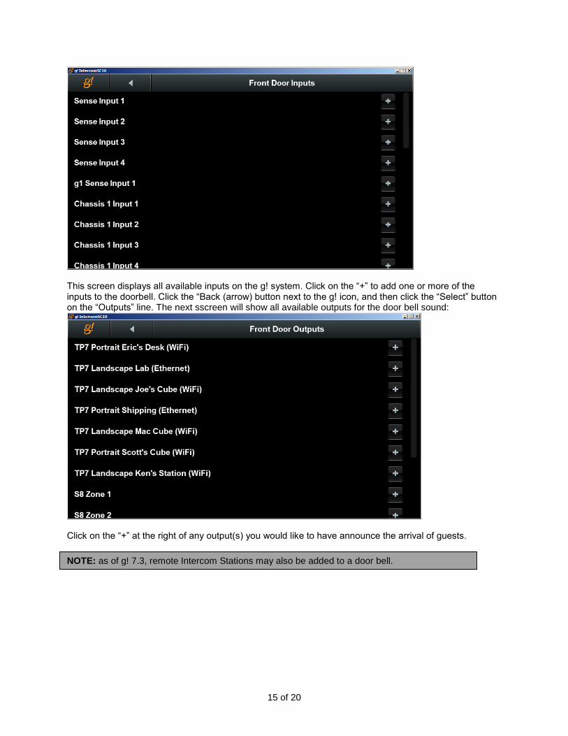
15 of 20
This screen displays all available inputs on the g! system. Click on the “+” to add one or more of the inputs to the doorbell. Click the “Back (arrow) button next to the g! icon, and then click the “Select” button on the “Outputs” line. The next sscreen will show all available outputs for the door bell sound:
Click on the “+” at the right of any output(s) you would like to have announce the arrival of guests.
NOTE: as of g! 7.3, remote Intercom Stations may also be added to a door bell.

16 of 20
TRADITIONAL DOORBELL (USE FOR ELAN S86) While ELAN recommends the use of the Enhanced Doorbell setup, it is possible to configure the Intercom to use a more traditional doorbell mode. The g1 will still be needed to provide the audio for the alerts. Please CAREFULLY follow the steps below to implement Doorbells in this manner.
I. Connect the Audio Out from the g1 Master or Extender to the Page In of the Zone Controller II. On the Media tab in Configurator, add a Generic Single Zone Controller
a. Name the Generic Single Zone Controller “Doorbell” b. Name the Zone “Doorbell” as well c. Assign the g1 Internal Player as Source 1
III. If using a SIP Doorstation as the Doorbell Trigger, on the Event Mapper tab a. Create a new event map
i. Add an Event 1. From System Family, select “Intercom” 2. Select the Door Station name from the list 3. Select “Incoming Call”
ii. Add a Command 1. From System Family select “Audio Zone Controllers” 2. Select your Zone Controller from the list 3. Select “Do Global Command” 4. Choose “Doorbell On”
iii. Add a Command 1. From System Family, select “General System” 2. Select “Delay Execution” 3. Set the delay to ten seconds.
iv. Add a Command 1. From System Family, select “Audio Zone Controllers” 2. Select your Zone Controller from the list 3. Select “Do Global Command” 4. Select “Doorbell Off”
IV. If using a Sense Input as the Doorbell Trigger, on the Event Mapper tab a. Create a new Event Map
i. Add an Event 1. From System Family, select “Inputs” 2. Select the input used for the trigger 3. Select “State: Off to On”
ii. Add a Command 1. From System Family select “Audio Zone Controllers” 2. Select your Zone Controller from the list 3. Select “Do Global Command” 4. Choose “Doorbell On”
iii. Add a Command 1. From System Family, select “General System” 2. Select “Delay Execution” 3. Set the delay to ten seconds.
iv. Add a Command 1. From System Family, select “Audio Zone Controllers” 2. Select your Zone Controller from the list 3. Select “Do Global Command” 4. Select “Doorbell Off”

17 of 20
DOOR STATIONS
A Door Station is a stand-alone device that is placed outside the home. It is capable of communicating with the ELAN SIP server, providing paging and two-way communication with visitors. Often a door station will incorporate a camera to allow the homeowner to see who is at the door. As of g! Core Module 7.3, functionality is also provided for actuating Door Station relays to provide entry through the use of a door strike. Please see the Integration Note for your door station for specific details on proper configuration to work with g!. ELAN uses the concept of “Dial Plans” to determine to which stations a page is sent when the door station button is pressed. As of g! Core Module 7.3, the Dial Plans can also be used to ring a door bell chime throughout the home when the Door Station button is pressed. When the door station button is pressed, any touchscreen clients that are members of the Dial Plan will display the option to answer or decline the call:
As of ELAN Control 8.0, If an external camera is assigned to the Door Station in Configurator, the Incoming Call screen will display a thumbnail view of the camera. This is not possible with the standard RTSP Video Stream from the built-in camera on most door stations due to the need for first establishing a SIP connection before the RTSP stream can be initiated. It MAY be possible to add the built-in camera as a Video Stream on the Video tab on Configurator using the Generic URL Video Camera device if the manufacturer can provide the URL for the video feed.
CONFIGURING DIAL PLANS
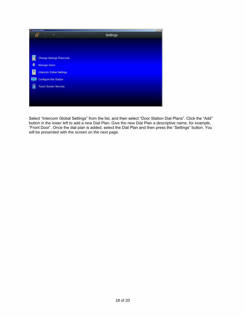
Dial Plans are configured through the g! Viewer. Multiple Dial Plans can exist on a system to help differentiate between calls coming in from various Door Stations. This configuration may be done with a touchscreen or from a computer running the viewer software. From the main Viewer menu, select the gear icon in the upper right corner. You will be prompted for the settings access code. By default, this code is “1234”. Once the code is entered, you will be taken to the main settings page:
18 of 20
Select “Intercom Global Settings” from the list, and then select “Door Station Dial Plans”. Click the “Add” button in the lower left to add a new Dial Plan. Give the new Dial Plan a descriptive name, for example, “Front Door”. Once the dial plan is added, select the Dial Plan and then press the “Settings” button. You will be presented with the screen on the next page.

19 of 20
To set up a Door Bell to play through zones on an Audio Zone Controller when the Door Station Button is pressed, first select a sound to play. Note that a g1 connected to the Audio Zone is required for this functionality as it is with a Sense Input door bell.
Once a sound is selected, press the “Select” button next to “Targets” to assign Audio Zones for the Door Bell.
DIAL PLAN TIERS
Two “Tiers” are available for each Dial Plan. Having multiple tiers allows you to set up certain stations to have priority when the door station is activated. A delay or Timeout will occur between the station attempting to contact Tier 1 and Tier 2 targets. Setting up a second Tier is optional.
In version 8 and newer, when using a door station with an external camera, a video thumbnail may be optionally added to the “Answer” screen when the Door Station is activated. This is possible because the Video Stream is not using the RTSP Protocol, so the video may be shown independently without first establishing a connection.
NOTE: g! releases prior to 7.3 will not have the option to add a Door Bell to a Dial Plan.
NOTE: As of g! 7.3, Remote intercom stations can also be added to Dial Plans
20 of 20
COMMON MISTAKES
1. Not using the correct sensor. The Sense Inputs on gSC and g1 controllers are not simple contact closures. To operate, an ELAN Sense module is required.
2. Using the Page Input on a Zone Controller while using the Enhanced Intercom. If using the Page In is required, separate triggers will be needed and a Generic Single Zone Controller needs to be used. Please see the section in this document regarding “Traditional Paging”.
3. No video options with OSD Intercom. Make sure that the BSPUPGRADE utility has been run against the g1 Extender.
4. iOS Call Answering- After the release of iOS 10, it is now necessary to do a “3d tap” by pressing the notification hard in order to answer an incoming call.