integration of marker-free selection of single cells at a
TRANSCRIPT
ChemicalScience
EDGE ARTICLE
Ope
n A
cces
s A
rtic
le. P
ublis
hed
on 2
6 N
ovem
ber
2018
. Dow
nloa
ded
on 2
/14/
2022
7:0
4:42
PM
. T
his
artic
le is
lice
nsed
und
er a
Cre
ativ
e C
omm
ons
Attr
ibut
ion-
Non
Com
mer
cial
3.0
Unp
orte
d L
icen
ce.
View Article OnlineView Journal | View Issue
Integration of m
Department of Chemistry, Iowa State Un
† Electronic supplementary information (details of experimental procedures, aexchange, lysis, and uidic isolation steps
Cite this: Chem. Sci., 2019, 10, 1506
All publication charges for this articlehave been paid for by the Royal Societyof Chemistry
Received 27th October 2018Accepted 25th November 2018
DOI: 10.1039/c8sc04804e
rsc.li/chemical-science
1506 | Chem. Sci., 2019, 10, 1506–1513
arker-free selection of single cellsat a wireless electrode array with parallel fluidicisolation and electrical lysis†
Min Li and Robbyn K. Anand *
We present integration of selective single-cell capture at an array of wireless electrodes (bipolar electrodes,
BPEs) with transfer into chambers, reagent exchange, fluidic isolation and rapid electrical lysis in a single
platform, thus minimizing sample loss and manual intervention steps. The whole process is achieved
simply by exchanging the solution in a single inlet reservoir and by adjusting the applied voltage at a pair
of driving electrodes, thus making this approach particularly well-suited for a broad range of research
and clinical applications. Further, the use of BPEs allows the array to be scalable to increase throughput.
Specific innovations reported here include the incorporation of a leak channel to balance competing
flow paths, the use of ‘split BPEs’ to create a distinct recapture and electrical lysis point within the
reaction chamber, and the dual purposing of an ionic liquid as an immiscible phase to seal the chambers
and as a conductive medium to permit electrical lysis at the split BPEs.
Introduction
Here we report a scalable dielectrophoretic cell array that inte-grates marker-free selection and sequestration of single cellswith parallel lysis to prepare for analysis in one microuidicplatform. This approach is signicant because (i) it addressesa need for development of versatile devices that integrate allsteps needed for single-cell analysis (selection, isolation,assays), (ii) the whole manipulation process (capture, transfer,retention, and electrical lysis) was valve-free and achieved byonly adjusting the applied voltage and exchanging the uid ina single inlet, and (iii) the use of wireless bipolar electrodes(BPEs) allows facile arraying for increased throughput.
Analysis of the composition and response of individual cellsallows unique and differentiated subpopulations of cells to bedelineated.1 Understanding cell-to-cell heterogeneity, such as inthe expression of a particular gene2 or protein,3 concentration ofan ion,4 or differences in regulatory and signaling patterns,5
helps dene their distinct roles in disease states. In pathologiesthat are driven by a minority of cells, broad access to suchinformation in research and clinical settings could revolu-tionize medicine. For instance, in cancer biology, the interro-gation of individual circulating tumor cells (CTCs) provides keyinformation that can inform therapeutic decisions.6 However,the enormous value of CTCs has not been completely realized
iversity, Ames, IA 50011, USA. E-mail:
ESI) available: Materials and methods,nd supplementary results of uid. See DOI: 10.1039/c8sc04804e
because accurate cellular selection of CTCs is made challengingby their varied physical and biological characteristics andextreme rarity.7 For such rare cell applications, a key point isthat integration of selection with parallel isolation and analysisof individual cells reduces device complexity and the likelihoodof cell loss.
Many microuidic lab-on-a-chip (LOC) technologies havebeen developed for manipulation and sampling of cells.8
However, they oen suffer from the following issues: (i) mostmethods for single-cell isolation are not selective. Cellspassively settle into divots9 or nanowells10 or are uidicallyaligned prior to encapsulation into droplets.11 Selection musthappen prior to the isolation step, and therefore, the overallprocess is necessarily modular. (ii) Selection methods based onimmunoaffinity12 or size13 are either over-selective and misscertain cell populations, thus biasing results, or are under-selective and do not result in highly pure samples. (iii) Mostexisting capture and detectionmethods are not easily interfacedwith assays. Aer capture, cells remain trapped on pillars,14
have been altered by molecular labels/tags,15 or become lostduring transit to a secondary device.16 To facilitate assays inconned microstructures, embedded microvalves with a largenumber of control lines are oen required.8b,17 The engineeringcomplexity of these microvalves hinders their application inmany research and clinical settings. Further, despite therebeingmany lysis methods reported in microuidics, integrationof cell lysis with other functions to make a complete diagnosticsystem remains rare.18 Thus, development of fully integrateddevices that offer simplicity in manufacturing and operationremains an important challenge.
This journal is © The Royal Society of Chemistry 2019

Scheme 1 (a) Principles of pDEP attraction and nDEP repulsion in anexternal electric field and (b and c) near a BPE tip.
Edge Article Chemical Science
Ope
n A
cces
s A
rtic
le. P
ublis
hed
on 2
6 N
ovem
ber
2018
. Dow
nloa
ded
on 2
/14/
2022
7:0
4:42
PM
. T
his
artic
le is
lice
nsed
und
er a
Cre
ativ
e C
omm
ons
Attr
ibut
ion-
Non
Com
mer
cial
3.0
Unp
orte
d L
icen
ce.
View Article Online
Among cell manipulation techniques, dielectrophoresis(DEP) has distinct advantages in that it is highly selective,antibody independent and exhibits high output cell viability.19
Recent studies have demonstrated that this selectivity stemsfrom biophysical properties with high biological relevance.20
Despite these advantages, most DEP sorting designs are notreadily paired with single-cell assays. For instance, in dielec-trophoretic eld-ow fractionation (DEP-FFF),21 high-throughput continuous sorting of rare cells is achieved, butcells are not captured individually. Additionally, DEP-basedstrategies that integrate selection with analysis are frequentlysequential, limiting throughput, or require transport of the cellsfor off-chip analysis, which risks cell loss.22 The Fujii grouppioneered DEP capture in microwells for high-throughputanalysis of conned cell lysates.23 However, the geometricconstraints placed on the microwells limited the reactionvolumes to only 56 pL, which is insufficient for certain assayssuch as single-cell RT-qPCR.24 Further, sealing microwells relieson mechanical actuation that collapses the overlying uidicstructure onto the array. An alternative DEP design that removesthese constraints would improve design exibility and betterprevent crosstalk.
We previously developed the use of DEP at a BPE array toaddress the need for selective and high-throughput single-cellcapture.7 In this device, BPE tips aligned to cell-sized micro-pockets accomplished individual capture of CTCs from a back-ground of white blood cells (WBCs). BPEs do not require wireleads, which thereby allowed bifurcation to 32 parallel micro-channels, greatly increasing throughput. In this way, this designtook advantage of the ability of a BPE – a conductor immersedin an ionically conductive phase – to polarize in response to anexternally applied electric eld via charging of the electricaldouble layer (EDL) at its opposite ends.25 This charging effectcommunicates the voltage applied at just two driving electrodesacross the entire BPE array. BPEs are versatile and have beenemployed previously for screening electrocatalysts,26,27
imaging,27 sensing,27,28 materials synthesis,29 micromotors,30
desalination,31 preconcentration of ionic species,32 and forDEP.7,33
This preliminary design did not incorporate reactionvolumes for on-chip assays (e.g., for mutations, transcripts, orenzymatic activity). Separately, we recently reported insulatingDEP (iDEP) capture at cell-sized constrictions and uidictransfer of these cells into co-planar ow-through reactionchambers followed by thermal lysis and loop-mediated ampli-cation (LAMP).34 This design utilizes the self-digitization (SD)principle to address the need for an isolated reaction volumes –an oil phase lled the uidic channel and sealed off thechambers. A key advantage of this design is that capture effi-ciency is decoupled from the geometry of the reaction chamber,and therefore, the reaction volume could be independentlytuned. However, the ow-through reaction chamber and tradi-tional electrodes employed are not readily amenable to a bifur-cation scheme, thus limiting throughput. Further, the uidicresistance of these chambers was sufficiently low that imbal-ances in pressure resulted in both disruption of cell capture andintrusion of oil into the chamber.
This journal is © The Royal Society of Chemistry 2019
In this paper, we integrate the advantages of both the BPEand SD schemes to accomplish selection, isolation, and elec-trical lysis – the steps required prior to molecular analysis of thecontents of individual cells – in a valve-free and robust platformwith a single inlet. While the approach is conceptually similar tothe electroactive microwell device introduced by Fujii andcoworkers, there are three key distinctions. First, there is onlyone uidic layer, which greatly simplies fabrication. Second,cell capture is accomplished at the reaction chamber inlet(instead of at the bottom of a reaction well), which criticallyprovides independent control over reaction volume and captureefficiency. Third, andmost importantly, the cell assay structuresare readily uidically isolated by an immiscible phase (SDprinciple) to prevent assay crosstalk. Beyond a simple combi-nation of the BPE and SD schemes, a separate innovation is theincorporation of a split BPE inside the reaction chamber thatallows electric eld-directed cell recapture and electrical lysis.Finally, the use of ionic liquid (IL) as an electrically conductivesubstitute for oil allowed electrical lysis. These functions areaccomplished with minimal peripheral equipment – a powersupply and a microscope – thus increasing the relevance of thisplatform to broad application in research and clinicallaboratories.
Results and discussion
As shown in Scheme 1a, DEP is a eld-induced force exerted ona particle due to the interaction of the particle's frequency-dependent dipole moment with the spatial gradient of theelectric eld. Scheme 1b and c illustrate the pDEP and nDEPresponses that we observed for model CTCs and WBCs,respectively, in our previously reported device.7 We have nowadvanced this design to enable analysis of the captured cells.Scheme 2a is an image of the device, which notably has onlya single inlet and outlet and two electrical leads. Scheme 2b–hillustrate the steps of operation: (b) when an AC electric eld isapplied, cells of interest are selectively separated from theowing sample and individually isolated in the pockets; (c andd) by turning the AC eld ‘off’ and then ‘on’ again, the capturedsingle-cells are further directed forward and retained at thecenter of the reaction chambers between adjacent BPE tips. (e)At this juncture, the uid can be exchanged if warranted by theassay; (f) the microchannel is then lled with a hydrophobic ILto uidically isolate the chambers. (g) Optionally, the AC eldstrength can then be increased to lyse captured cells. (h) Thisapproach is therefore amenable to live cell assays or interro-gation of cell contents.
Chem. Sci., 2019, 10, 1506–1513 | 1507

Scheme 2 (a) Picture of themicrofluidic chip. The channels are filled with red food dye to show detail. A coin is shown at the side for scale. (b–h)Schematic overview of the current approach.
Chemical Science Edge Article
Ope
n A
cces
s A
rtic
le. P
ublis
hed
on 2
6 N
ovem
ber
2018
. Dow
nloa
ded
on 2
/14/
2022
7:0
4:42
PM
. T
his
artic
le is
lice
nsed
und
er a
Cre
ativ
e C
omm
ons
Attr
ibut
ion-
Non
Com
mer
cial
3.0
Unp
orte
d L
icen
ce.
View Article Online
Leak channel enables valve-free transport and isolation ofindividual cells
In our previous work,7 cell-scale micropockets extruding fromeither side of each microchannel ensured that individual cellswere captured at each electrode tip. Here, reaction chambers areintroduced adjacent to the pockets to store a sufficient amountof reagent solution (2.0 nL) for single-cell assay. Transfer of eachcell from pocket to chamber must be accomplished to increasecontact area between cells and reagents. However, the li forcecreated by uid ow in the channel can easily pull the cell out ofthe pocket, once the capture voltage is turned off, and therebyimpedes cell transfer into the chamber. Fig. 1 shows the resultsof cell transfer in the absence of a leak channel design. Fig. 1a isa surface plot showing the total uid ow velocity in a segment
Fig. 1 Results of the cell transfer step in the absence of a leak channel.(a) Simulated contours of the flow velocity and streamlines of thedevice when a cell is captured in the pocket. All pocket corners arefilleted by 10 mm. (b) Numerical simulation of the total force experi-enced by a cell along the y-direction as a function of the distance ofthe far edge of a cell to themain channel. The inlet velocity of the mainchannel was set to 100 mm s�1. (c and d) Brightfield images of cellcaptured and transfer when AC is on (c) and off (d). The grey arrowsrepresent the flow direction.
1508 | Chem. Sci., 2019, 10, 1506–1513
of the main channel and a micropocket that contains a cell(represented by a white circle). In the y-direction, the cellexperiences li force (pressure force, towards the main channel)and drag force (viscous force, towards the chamber), while inthe x-direction, only drag force is exerted on the cell. Positivetotal force along the y-direction is required for forward move-ment into reaction chambers. Fig. 1b is the computed result ofthe total force (FTotal) exerted on a cell when it is located in thepocket. The x-axis, as depicted in Fig. 1a, is the distance of thefarthest edge of a cell (20.0 mm diameter) from the mainchannel opening. Importantly, this result was simulated fora design in which the reaction chamber has no additionaluidic connection (i.e., no leak channel). The BPE is not shown.Fig. 1c and d are sequential bright eld images that show theresult of turning off the AC voltage aer cell capture. From thisresult, it can be concluded that in the absence of a leak channel,the drag force along the y-direction is negligible, while the liforce created by uid ow can easily pull the cell out of thepocket. Additionally, a rounded pocket corner enhances liforce, and thereby impedes cell transfer. Based on the results,sharp pocket corners are desired, and it is further apparent thatan additional force is required to push cells forward into thereaction chambers.
We address this need by introducing a leak channel, whichinduces an additional drag force perpendicular to the mainchannel by forming a ow pathway into the micropocket andout of the leak channel (Fig. 2a). To investigate the inuence ofleak channel width and BPE location on cell transfer, the totalforce exerted on captured cells was computed (Fig. 2b). Basedon these results, it can be concluded that FDrag is very sensitiveto leak channel resistance, which increases exponentially withdecreasing hydraulic radius. A 7 mm width permitted cell entryinto the chamber without creating excessive drag force (strongerthan DEP capture force), and was therefore chosen for subse-quent experiments. Additionally, a distance (d, Fig. 2a) of 25–35mm from the main channel to the farthest edge of the cell (20mmdiameter) prevents the cell from being washed away withoutcompromising capture efficiency. It was found experimentallythat this capture position was best achieved with a BPE tippositioned 5–15 mm inside the pocket.
This journal is © The Royal Society of Chemistry 2019
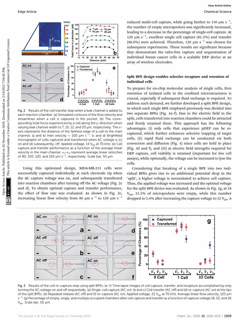
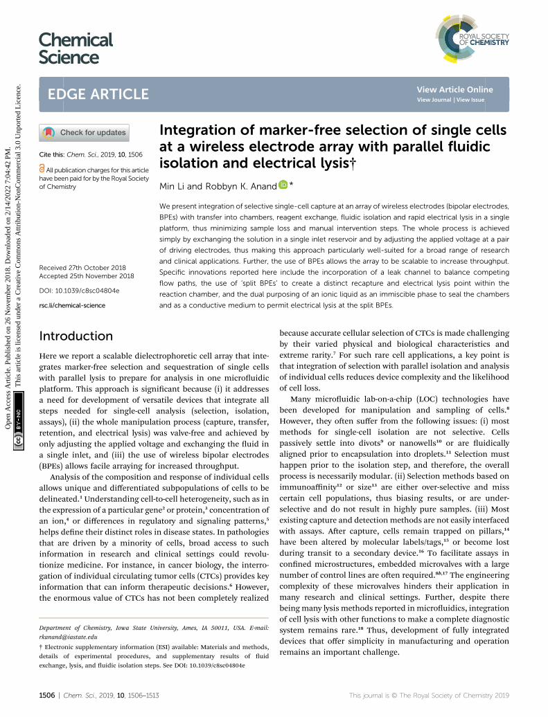
Fig. 2 Results of the cell transfer step when a leak channel is added toeach reaction chamber. (a) Simulated contours of the flow velocity andstreamlines when a cell is captured in the pocket. (b) The corre-sponding total force experienced by a cell along the y-direction whenvarying leak channel width to 7, 10, 12, and 20 mm, respectively. The x-axis represents the distance of the farthest edge of a cell to the mainchannel. (a and b) Inlet velocity ¼ 100 mm s�1. (c and d) Brightfieldmicrographs of cells captured and transferred when AC voltage is (c)on and (d) subsequently, off. Applied voltage, 14 Vpp at 70 kHz. (e) Cellcapture and transfer performance as a function of the average linearvelocity in the main channel. y1–y4 represent average linear velocitiesof 80, 100, 120, and 150 mm s�1, respectively. Scale bar, 50 mm.
Edge Article Chemical Science
Ope
n A
cces
s A
rtic
le. P
ublis
hed
on 2
6 N
ovem
ber
2018
. Dow
nloa
ded
on 2
/14/
2022
7:0
4:42
PM
. T
his
artic
le is
lice
nsed
und
er a
Cre
ativ
e C
omm
ons
Attr
ibut
ion-
Non
Com
mer
cial
3.0
Unp
orte
d L
icen
ce.
View Article Online
Using this optimized design, MDA-MB-231 cells weresuccessfully captured individually at each electrode tip whenthe AC capture voltage was on, and subsequently transferredinto reaction chambers aer turning off the AC voltage (Fig. 2cand d). To obtain optimal capture and transfer performance,the effect of ow rate was evaluated. As shown in Fig. 2e,increasing linear ow velocity from 80 mm s�1 to 120 mm s�1
Fig. 3 Results of the cell re-capture step using split BPEs. (a–f) Time lapsturning the AC voltage on and off sequentially. (a) Single-cell capture (ACof the split BPEs. (e) Repeated release (AC off) and (f) re-capture (AC on).s�1. (g) Percentage of empty, singly, andmultiply occupied chambers afteVpp. Scale bar, 50 mm.
This journal is © The Royal Society of Chemistry 2019
reduced multi-cell capture, while going further to 150 mm s�1,the number of empty micropockets was signicantly increased,leading to a decrease in the percentage of single-cell capture. At120 mm s�1, excellent single cell capture (81.2%) and transfer(88.0%) were achieved. Therefore, 120 mm s�1 was chosen forsubsequent experiments. These results are signicant becausethey demonstrate the valve-free capture and sequestration ofindividual breast cancer cells in a scalable DEP device at anarray of wireless electrodes.
Split BPE design enables selective recapture and retention ofindividual cells
To prepare for on-chip molecular analysis of single cells, rmretention of isolated cells in the conned microstructures iscrucial, especially if subsequent uid exchange is required. Toaddress such demand, we further developed a split BPE design,in which each single BPE employed previously was divided intotwo separate BPEs (Fig. 3a–f). Due to the electric eld in thesplit, cells transferred into reaction chambers could be attractedand rmly retained there. This approach has the followingadvantages: (i) only cells that experience pDEP can be re-captured, which further enhances selective trapping of targetcells, (ii) rapid uid exchange can be conducted via bothconvection and diffusion (Fig. 4) since cells are held in place(Fig. 3d and f), and (iii) at electric eld strengths required forDEP capture, cell viability is retained (important for live cellassays), while optionally, the voltage can be increased to lyse thecells.
Considering that breaking of a single BPE into two indi-vidual BPEs gives rise to an additional potential drop in the‘split’, a higher voltage is necessitated to achieve cell capture.Thus, the applied voltage was increased and the optimal voltagefor the split BPE device was evaluated. As shown in Fig. 3g, at 18Vpp, 23.3% of micropockets were empty, while this numberdropped to 5.4% aer increasing the capture voltage to 22 Vpp. A
e images of cell capture, transfer, and recapture accomplished by onlyon). (b and c) Cell transfer (AC off) and (d) re-capture (AC on) at the tipsApplied voltage, 22 Vpp at 70 kHz. Average linear flow velocity, 120 mmr cell capture and transfer as a function of capture voltage 18, 22, and 26
Chem. Sci., 2019, 10, 1506–1513 | 1509
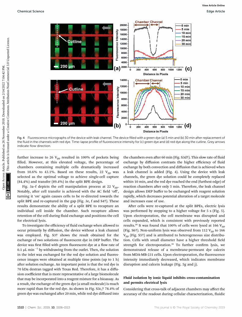
Fig. 4 Fluorescencemicrographs of the device with leak channel. The device filled with a green dye (a) 5 min and (b) 30min after replacement ofthe fluid in the channels with red dye. Time-lapse profile of fluorescence intensity for (c) green dye and (d) red dye along the cutline. Grey arrowsindicate flow direction.
Chemical Science Edge Article
Ope
n A
cces
s A
rtic
le. P
ublis
hed
on 2
6 N
ovem
ber
2018
. Dow
nloa
ded
on 2
/14/
2022
7:0
4:42
PM
. T
his
artic
le is
lice
nsed
und
er a
Cre
ativ
e C
omm
ons
Attr
ibut
ion-
Non
Com
mer
cial
3.0
Unp
orte
d L
icen
ce.
View Article Online
further increase to 26 Vpp resulted in 100% of pockets beinglled. However, at this elevated voltage, the percentage ofchambers containing multiple cells dramatically increasedfrom 10.6% to 43.1%. Based on these results, 22 Vpp wasselected as the optimal voltage to achieve single-cell capture(84.4%) and transfer (89.4%) in the split BPE design.
Fig. 3a–f depicts the cell manipulation process at 22 Vpp.Notably, aer cell transfer is achieved with the AC eld ‘off’,turning it ‘on’ again causes cells to be re-directed towards thesplit BPE and re-captured in the gap (Fig. 3e, f and S4†). Theseresults demonstrate the ability of a split BPE to recapture anindividual cell inside the chamber. Such recapture allowsretention of the cell during uid exchange and positions the cellfor electrical lysis.
To investigate the efficiency of uid exchange when allowed tooccur primarily by diffusion, the device without a leak channelwas employed. Fig. S3† shows the result obtained for theexchange of two solutions of uorescent dye in DEP buffer. Thedevice was rst lled with green uorescent dye at a ow rate of0.1 mL min�1 by withdrawing from the outlet. Then, the solutionin the inlet was exchanged for the red dye solution and uores-cence images were obtained at multiple time points (up to 1 h)aer solution exchange. An important point is that the red dye is70 kDa dextran tagged with Texas Red. Therefore, it has a diffu-sion coefficient that is more representative of a large biomoleculethat may be incorporated into a reagentmixture for a bioassay. Asa result, the exchange of the green dye (a small molecule) ismuchmore rapid than for the red dye. As shown in Fig. S3c,† 78.4% ofgreen dye was exchanged aer 20min, while red dye diffused into
1510 | Chem. Sci., 2019, 10, 1506–1513
the chambers even aer 60min (Fig. S3d†). This slow rate of uidexchange by diffusion contrasts the higher efficiency of uidexchange by both convection and diffusion that is achieved whena leak channel is added (Fig. 4). Using the device with leakchannels, the green dye solution could be completely replacedwithin 10 min, and the red dye reached the end (furthest edge) ofreaction chambers aer only 5 min. Therefore, the leak channeldesign allows DEP buffer to be exchanged with reagent solutionrapidly, which decreases potential alteration of a target moleculeand increases ease of use.
Aer cells were re-captured at the split BPEs, electric lysiswas performed by stepping to a higher voltage for 5 s (Fig. 5).Upon electroporation, the cell membrane was disrupted andcells expanded, which is consistent with previously reportedresults.35 It was found that 100% of cells were lysed at 166 Vpp
(Fig. S6†). Non-uniform lysis was observed from 112 Vpp to 166Vpp (Fig. S5†) and is attributed to heterogeneous size distribu-tion. Cells with small diameter have a higher threshold eldstrength for electroporation.35 To further conrm lysis, wedemonstrated release of a membrane-permeant dye calceinfromMDA-MB-231 cells. Upon electroporation, the uorescenceintensity immediately decreased, which indicates membranedisruption and calcein leakage (Fig. 5g and j).
Fluid isolation by ionic liquid inhibits cross-contaminationand permits electrical lysis
Considering that cross-talk of adjacent chambers may affect theaccuracy of the readout during cellular characterization, uidic
This journal is © The Royal Society of Chemistry 2019
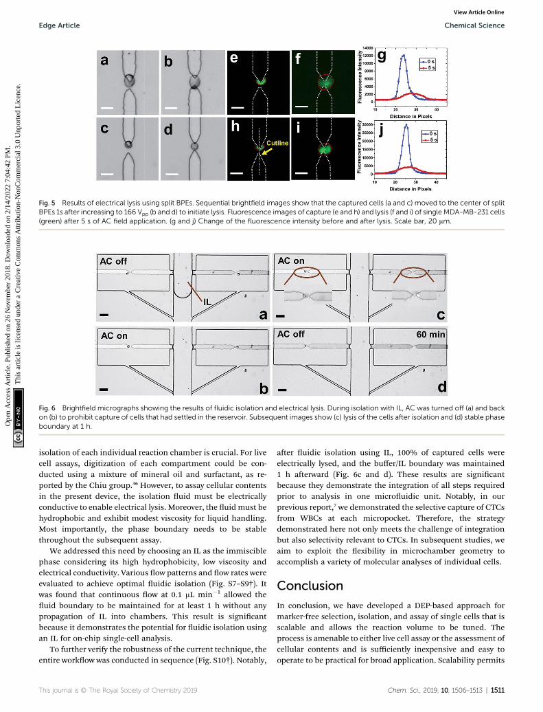
Fig. 5 Results of electrical lysis using split BPEs. Sequential brightfield images show that the captured cells (a and c) moved to the center of splitBPEs 1s after increasing to 166 Vpp (b and d) to initiate lysis. Fluorescence images of capture (e and h) and lysis (f and i) of single MDA-MB-231 cells(green) after 5 s of AC field application. (g and j) Change of the fluorescence intensity before and after lysis. Scale bar, 20 mm.
Fig. 6 Brightfield micrographs showing the results of fluidic isolation and electrical lysis. During isolation with IL, AC was turned off (a) and backon (b) to prohibit capture of cells that had settled in the reservoir. Subsequent images show (c) lysis of the cells after isolation and (d) stable phaseboundary at 1 h.
Edge Article Chemical Science
Ope
n A
cces
s A
rtic
le. P
ublis
hed
on 2
6 N
ovem
ber
2018
. Dow
nloa
ded
on 2
/14/
2022
7:0
4:42
PM
. T
his
artic
le is
lice
nsed
und
er a
Cre
ativ
e C
omm
ons
Attr
ibut
ion-
Non
Com
mer
cial
3.0
Unp
orte
d L
icen
ce.
View Article Online
isolation of each individual reaction chamber is crucial. For livecell assays, digitization of each compartment could be con-ducted using a mixture of mineral oil and surfactant, as re-ported by the Chiu group.36 However, to assay cellular contentsin the present device, the isolation uid must be electricallyconductive to enable electrical lysis. Moreover, the uidmust behydrophobic and exhibit modest viscosity for liquid handling.Most importantly, the phase boundary needs to be stablethroughout the subsequent assay.
We addressed this need by choosing an IL as the immisciblephase considering its high hydrophobicity, low viscosity andelectrical conductivity. Various ow patterns and ow rates wereevaluated to achieve optimal uidic isolation (Fig. S7–S9†). Itwas found that continuous ow at 0.1 mL min�1 allowed theuid boundary to be maintained for at least 1 h without anypropagation of IL into chambers. This result is signicantbecause it demonstrates the potential for uidic isolation usingan IL for on-chip single-cell analysis.
To further verify the robustness of the current technique, theentire workow was conducted in sequence (Fig. S10†). Notably,
This journal is © The Royal Society of Chemistry 2019
aer uidic isolation using IL, 100% of captured cells wereelectrically lysed, and the buffer/IL boundary was maintained1 h aerward (Fig. 6c and d). These results are signicantbecause they demonstrate the integration of all steps requiredprior to analysis in one microuidic unit. Notably, in ourprevious report,7 we demonstrated the selective capture of CTCsfrom WBCs at each micropocket. Therefore, the strategydemonstrated here not only meets the challenge of integrationbut also selectivity relevant to CTCs. In subsequent studies, weaim to exploit the exibility in microchamber geometry toaccomplish a variety of molecular analyses of individual cells.
Conclusion
In conclusion, we have developed a DEP-based approach formarker-free selection, isolation, and assay of single cells that isscalable and allows the reaction volume to be tuned. Theprocess is amenable to either live cell assay or the assessment ofcellular contents and is sufficiently inexpensive and easy tooperate to be practical for broad application. Scalability permits
Chem. Sci., 2019, 10, 1506–1513 | 1511

Chemical Science Edge Article
Ope
n A
cces
s A
rtic
le. P
ublis
hed
on 2
6 N
ovem
ber
2018
. Dow
nloa
ded
on 2
/14/
2022
7:0
4:42
PM
. T
his
artic
le is
lice
nsed
und
er a
Cre
ativ
e C
omm
ons
Attr
ibut
ion-
Non
Com
mer
cial
3.0
Unp
orte
d L
icen
ce.
View Article Online
sampling and analysis of larger input volumes. The currentdevice has 2 parallel channels in a footprint of 15.6 mm2 and 40reaction chambers. However, we previously demonstratedbifurcation to 32 parallel channels, which with 640 chamberswould approach 2.5 cm2 and about 18 mL h�1 throughput,which is effective for many applications. The technology re-ported here is broadly applicable to individual analysis of manycell types and has a distinct advantage where cell phenotypesare distinguishable by their electrophysiological properties. Inthe context of CTCs, these dielectric properties are a muchmorespecic differentiator of phenotype than size alone while notbeing as overly selective as a single biomarker such as EpCAM.Toner and coworkers recently demonstrated the wide range ofCTC size and EpCAM expression thereby underscoring the needfor alternatives to size- and antibody-based capture.37 This studyis a premier example of the cutting edge in CTC detection, andimportantly, it clearly demonstrates where there is remainingneed – namely, to interface cell selection with single-cell isola-tion and subsequent assays. We anticipate that the platformreported here would be appropriate as secondary to an inlinepre-sort for nucleated cells (e.g., by lateral displacement) with orwithout WBC depletion37 or to pre-enrichment by acousto-phoresis.19b Finally, the isolation of individual cells at an arrayof wireless electrodes (BPEs), which are also frequentlyemployed for sensing,38 presents the possibility for futureintegration of this technology with electrochemical methods ofcell analysis.39
Conflicts of interest
There are no conicts to declare.
Acknowledgements
The authors thank Prof. Jared Anderson and He Nan forproviding ionic liquid samples for testing.
References
1 (a) X. Chen, J. C. Love, N. E. Navin, L. Pachter,M. J. Stubbington, V. Svensson, J. V. Sweedler andS. A. Teichmann, Nat. Biotechnol., 2016, 34, 1111–1118; (b)L. Zhang and A. Vertes, Angew. Chem., Int. Ed., 2018, 57,4466–4477.
2 C. Gawad, W. Koh and S. R. Quake, Nat. Rev. Genet., 2016, 17,175–188.
3 S. S. Agasti, M. Liong, V. M. Peterson, H. Lee andR. Weissleder, J. Am. Chem. Soc., 2012, 134, 18499–18502.
4 L. Li, Y. Fan, Q. Li, R. Sheng, H. Si, J. Fang, L. Tong andB. Tang, Anal. Chem., 2017, 89, 4559–4565.
5 Q. Shi, L. Qin, W. Wei, F. Geng, R. Fan, Y. S. Shin, D. Guo,L. Hood, P. S. Mischel and J. R. Heath, Proc. Natl. Acad. Sci.U. S. A., 2012, 109, 419–424.
6 S. A. Joosse, T. M. Gorges and K. Pantel, EMBO Mol. Med.,2015, 7, 1–11.
7 M. Li and R. K. Anand, J. Am. Chem. Soc., 2017, 139, 8950–8959.
1512 | Chem. Sci., 2019, 10, 1506–1513
8 (a) B. J. Green, T. Saberi Safaei, A. Mepham, M. Labib,R. M. Mohamadi and S. O. Kelley, Angew. Chem., Int. Ed.,2016, 55, 1252–1265; (b) R. N. Zare and S. Kim, Annu. Rev.Biomed. Eng., 2010, 12, 187–201.
9 D. Di Carlo, L. Y. Wu and L. P. Lee, Lab Chip, 2006, 6, 1445–1449.
10 S. M. Park, D. J. Wong, C. C. Ooi, D. M. Kurtz, O. Vermesh,A. Aalipour, S. Suh, K. L. Pian, J. J. Chabon, S. H. Lee,M. Jamali, C. Say, J. N. Carter, L. P. Lee, W. G. Kuschner,E. J. Schwartz, J. B. Shrager, J. W. Neal, H. A. Wakelee,M. Diehn, V. S. Nair, S. X. Wang and S. S. Gambhir, Proc.Natl. Acad. Sci. U. S. A., 2016, 113, E8379–E8386.
11 H. N. Joensson and H. Andersson Svahn, Angew. Chem., Int.Ed., 2012, 51, 12176–12192.
12 (a) S. T. Wang, K. Liu, J. A. Liu, Z. T. F. Yu, X. W. Xu,L. B. Zhao, T. Lee, E. K. Lee, J. Reiss, Y. K. Lee,L. W. K. Chung, J. T. Huang, M. Rettig, D. Seligson,K. N. Duraiswamy, C. K. F. Shen and H. R. Tseng, Angew.Chem., Int. Ed., 2011, 50, 3084–3088; (b) S. Wang, H. Wang,J. Jiao, K. J. Chen, G. E. Owens, K. Kamei, J. Sun,D. J. Sherman, C. P. Behrenbruch, H. Wu and H. R. Tseng,Angew. Chem., Int. Ed., 2009, 48, 8970–8973.
13 (a) V. De Giorgi, P. Pinzani, F. Salvianti, J. Panelos,M. Paglierani, A. Janowska, M. Grazzini, J. Wechsler,C. Orlando, M. Santucci, T. Lotti, M. Pazzagli andD. Massi, J. Invest. Dermatol., 2010, 130, 2440–2447; (b)X. Fan, C. Jia, J. Yang, G. Li, H. Mao, Q. Jin and J. Zhao,Biosens. Bioelectron., 2015, 71, 380–386.
14 M. G. Ahmed, M. F. Abate, Y. Song, Z. Zhu, F. Yan, Y. Xu,X. Wang, Q. Li and C. Yang, Angew. Chem., Int. Ed., 2017,129, 10821–10825.
15 S. Hou, L. Zhao, Q. Shen, J. Yu, C. Ng, X. Kong, D. Wu,M. Song, X. Shi, X. Xu, W. H. OuYang, R. He, X. Z. Zhao,T. Lee, F. C. Brunicardi, M. A. Garcia, A. Ribas, R. S. Loand H. R. Tseng, Angew. Chem., Int. Ed., 2013, 52, 3379–3383.
16 J. Cemazar, T. A. Douglas, E. M. Schmelz and R. V. Davalos,Biomicrouidics, 2016, 10, 014109.
17 A. K. White, K. A. Heyries, C. Doolin, M. Vaninsberghe andC. L. Hansen, Anal. Chem., 2013, 85, 7182–7190.
18 L. Nan, Z. Jiang and X. Wei, Lab Chip, 2014, 14, 1060–1073.19 (a) Z. R. Gagnon, Electrophoresis, 2011, 32, 2466–2487; (b)
M. Li and R. K. Anand, Anal. Bioanal. Chem., 2018, 410,2499–2515.
20 A. R. Yale, J. L. Nourse, K. R. Lee, S. N. Ahmed, J. Arulmoli,A. Y. L. Jiang, L. P. McDonnell, G. A. Botten, A. P. Lee,E. S. Monuki, M. Demetriou and L. A. Flanagan, Stem CellRep., 2018, 11, 869–882.
21 P. R. Gascoyne, J. Noshari, T. J. Anderson and F. F. Becker,Electrophoresis, 2009, 30, 1388–1398.
22 (a) K. W. Huang, Y. C. Wu, J. A. Lee and P. Y. Chiou, Lab Chip,2013, 13, 3721–3727; (b) P. Zhang, L. Ren, X. Zhang, Y. Shan,Y. Wang, Y. Ji, H. Yin, W. E. Huang, J. Xu and B. Ma, Anal.Chem., 2015, 87, 2282–2289.
23 S. H. Kim and T. Fujii, Lab Chip, 2016, 16, 2440–2449.24 (a) A. Stahlberg and M. Kubista, Expert Rev. Mol. Diagn.,
2014, 14, 323–331; (b) Y. Gong, A. O. Ogunniyi andJ. C. Love, Lab Chip, 2010, 10, 2334–2337; (c) A. K. White,
This journal is © The Royal Society of Chemistry 2019

Edge Article Chemical Science
Ope
n A
cces
s A
rtic
le. P
ublis
hed
on 2
6 N
ovem
ber
2018
. Dow
nloa
ded
on 2
/14/
2022
7:0
4:42
PM
. T
his
artic
le is
lice
nsed
und
er a
Cre
ativ
e C
omm
ons
Attr
ibut
ion-
Non
Com
mer
cial
3.0
Unp
orte
d L
icen
ce.
View Article Online
M. VanInsberghe, O. I. Petriv, M. Hamidi, D. Sikorski,M. A. Marra, J. Piret, S. Aparicio and C. L. Hansen, Proc.Natl. Acad. Sci. U. S. A., 2011, 108, 13999–14004.
25 (a) F. Mavre, R. K. Anand, D. R. Laws, K.-F. Chow,B. Y. Chang, J. A. Crooks and R. M. Crooks, Anal. Chem.,2010, 82, 8766–8774; (b) S. E. Fosdick, K. N. Knust,K. Scida and R. M. Crooks, Angew. Chem., Int. Ed., 2013,52, 10438–10456; (c) G. Loget, D. Zigah, L. Bouffier,N. Sojic and A. Kuhn, Acc. Chem. Res., 2013, 46, 2513–2523.
26 (a) S. E. Fosdick, S. P. Berglund, C. B. Mullins andR. M. Crooks, ACS Catal., 2014, 4, 1332–1339; (b)S. E. Fosdick, S. P. Berglund, C. B. Mullins andR. M. Crooks, Anal. Chem., 2013, 85, 2493–2499; (c)X. Zhang, L. Zhang, Q. Zhai, W. Gu, J. Li and E. Wang,Anal. Chem., 2016, 88, 2543–2547; (d) X. Lin, L. Zheng,G. Gao, Y. Chi and G. Chen, Anal. Chem., 2012, 84, 7700–7707.
27 J. P. Guerrette, S. J. Percival and B. Zhang, J. Am. Chem. Soc.,2013, 135, 855–861.
28 (a) K.-F. Chow, F. Mavre and R. M. Crooks, J. Am. Chem. Soc.,2008, 130, 7544; (b) W. Xu, K. Fu and P. W. Bohn, ACS Sens.,2017, 2, 1020–1026; (c) A. Arora, J. C. T. Eijkel, W. E. Morf andA. Manz, Anal. Chem., 2001, 73, 3282–3288.
29 (a) J. C. Bradley and Z. Ma, Angew. Chem., Int. Ed., 1999, 38,1663–1666; (b) C. Ulrich, O. Andersson, L. Nyholm andF. Bjorefors, Angew. Chem., Int. Ed., 2008, 47, 3034–3036;(c) R. Ramaswamy and C. Shannon, Langmuir, 2010, 27,878–881; (d) S. Inagi, Y. Ishiguro, M. Atobe andT. Fuchigami, Angew. Chem., Int. Ed., 2010, 49, 10136–10139; (e) S. Ramakrishnan and C. Shannon, Langmuir,2010, 26, 4602–4606.
This journal is © The Royal Society of Chemistry 2019
30 (a) Z. Fattah, G. Loget, V. Lapeyre, P. Garrigue,C. Warakulwit, J. Limtrakul, L. Bouffier and A. Kuhn,Electrochim. Acta, 2011, 56, 10562–10566; (b) G. Loget andA. Kuhn, J. Am. Chem. Soc., 2010, 132, 15918–15919.
31 (a) K. N. Knust, D. Hlushkou, R. K. Anand, U. Tallarek andR. M. Crooks, Angew. Chem., Int. Ed., 2013, 52, 8107–8110;(b) E. Yoon, C. D. Davies, T. A. Hooper and R. M. Crooks,Lab Chip, 2017, 17, 2491–2499.
32 (a) R. K. Anand, E. Sheridan, K. Knust and R. M. Crooks,Anal. Chem., 2011, 83, 2351–2358; (b) D. R. Laws,D. Hlushkou, R. K. Perdue, U. Tallarek and R. M. Crooks,Anal. Chem., 2009, 81, 8923–8929; (c) K. Scida, E. Sheridanand R. M. Crooks, Lab Chip, 2013, 13, 2292–2299.
33 (a) R. K. Anand, E. S. Johnson and D. T. Chiu, J. Am. Chem.Soc., 2015, 137, 776–783; (b) Y. Wu, Y. Ren, Y. Tao, L. Houand H. Jiang, Anal. Chem., 2018, 90, 11461–11469.
34 Y. Qin, L. Wu, T. Schneider, G. S. Yen, J. Wang, S. Xu, M. Li,A. L. Paguirigan, J. L. Smith, J. P. Radich, R. K. Anand andD. T. Chiu, Angew. Chem., Int. Ed., 2018, 57, 11378–11383.
35 H. Y. Wang and C. Lu, Anal. Chem., 2006, 78, 5158–5164.36 D. E. Cohen, T. Schneider, M. Wang and D. T. Chiu, Anal.
Chem., 2010, 82, 5707–5717.37 F. Fachin, P. Spuhler, J. M. Martel-Foley, J. F. Edd,
T. A. Barber, J. Walsh, M. Karabacak, V. Pai, M. Yu,K. Smith, H. Hwang, J. Yang, S. Shah, R. Yarmush,L. V. Sequist, S. L. Stott, S. Maheswaran, D. A. Haber,R. Kapur and M. Toner, Sci. Rep., 2017, 7, 10936.
38 S. E. Fosdick, K. N. Knust, K. Scida and R. M. Crooks, Angew.Chem., Int. Ed., 2013, 52, 10438.
39 T. E. Lin, S. Rapino, H. H. Girault and A. Lesch, Chem. Sci.,2018, 9, 4546.
Chem. Sci., 2019, 10, 1506–1513 | 1513