integration of mechatronics design approach into teaching ... · (ironcad, autocad, inventor,...
TRANSCRIPT

Paper ID #11530
Integration of Mechatronics Design Approach into Teaching of Modeling Prac-tices
Dr. Vukica M. Jovanovic, Old Dominion University
Dr. Jovanovic received her dipl.ing and M.Sc. in Industrial Engineering from University of Novi Sad,Serbia. She received a PhD in Technology at Purdue University, while working as a PhD student in Cen-ter for Advanced Manufacturing, Product Lifecycle Management Center of Excellence. Dr. Jovanovic iscurrently serving as Assistant Professor of Engineering Technology, Frank Batten College of Engineeringand Technology at ODU. She is teaching classes in the area of mechatronics and computer aided engi-neering. In last fourteen years, she has teaching solid modelling in seven different software platforms(IronCAD, AutoCAD, Inventor, SolidWorks, Creo, Catia and NX) to over 600 students and 120 industrypractitioners. So far, she taught mechatronics related courses to around 240 students. She taught machineelements to 28 students.
Dr. Tatiana V. Goris, Purdue University, Columbus, IN
Dr. Tatiana Goris ([email protected]) is a Clinical Assistant Professor at Purdue University (Collegeof Technology at Columbus, IN). She teaches various undergraduate courses in Mechanical EngineeringTechnology. In 2012 Dr. Goris received her PhD in Technology from Purdue University, IN. She alsoobtained MS degree (1999) in Electronics Engineering from Taganrog Institute of Technology, Russia.
Dr. Ana M. Djuric, Wayne State University
Dr. Ana Djuric, Assistant Professor of Engineering Technology, will be a Co-PI and will bring her ex-pertise in mechanical engineering, more specifically in industrial robotics and manufacturing to the team.She developed new introductory Robotic theory course and two robotic modules with industry grants(Omnibus Fund Support of Instructional Technology and Industrial Equipment Grant from General Mo-tors). Dr. Djuric research areas are Industrial robots, kinematics, dynamics, and control and advancedmanufacturing systems.
Dr. Petros J Katsioloudis, Old Dominion University
Petros J. Katsioloudis is an Associate Professor and the Industrial Technology Program Leader, Depart-ment of STEM Education and Professional Studies, Old Dominion University, Norfolk, VA. His researchfocuses on improving teacher and student performance in STEM education, and enhancing the develop-ment of a national STEM-educated workforce.
Prof. Nathan John Luetke, Old Dominion University
Nathan Luetke Received his BS in Mechanical Engineering Technology from Old Dominion Universityfollowed shortly after by an MS in Mechanical Engineering. While Pursuing his Masters degree Nathanspent two years at Swales Aerospace followed by one year at Lockheed Martin contracting for NASA Lan-gley Research Center in Hampton, VA. While there he had the opportunity to perform radiation analysesand shield optimization on models of the International Space Station, possible lunar habitats and vehiclesfor transport to Mars in the effort to increase radiation mitigation for the astronauts and equipment. In thattime he co-authored eight conference proceedings and completed his MS degree with research focused onhigh-speed combustion and rocket-based combined cycles.
Nathan has focused his own research on the fuel mixing and combustion characteristics of dual-modescramjet engines, authoring and co-authoring four conference proceedings in addition to his work withradiation mitigation. Currently Nathan is a lecturer in the engineering technology department teachingCAD based courses, Thermodynamics and Fluid Mechanics. He is involved with the Thermodynamic andFluids laboratories and is interested in incorporating renewable energy systems into the lab environment.
Prof. Moustafa R. Moustafa, Old Dominion University
c©American Society for Engineering Education, 2015

Paper ID #11530
Professor Moustafa joined the Mechanical Engineering Technology department in August of 1979. Sincethen, he continuously taught, advised, guided and supervised students helping them to acquire the neces-sary knowledge, education, technical, ethical and communication skills. He is well respected and recog-nized by our graduates for his contributions resulting in their career successes. Moustafa is in charge ofthe senior design project for the mechanical engineering technology department. He encourages seniorsto work on practical projects. Some of these projects are provided by local industrial and manufacturingcorporations as a result of personal contacts and relationships with alumni. This interaction has provento be invaluable in the growth and development of our graduates and sometimes leads to hiring oppor-tunities. Moustafa has been instrumental in the development and offering of online senior classes to offcampus students in support of the growing trend of distance education Moustafa is the faculty advisor ofthe student chapter of the Society of Manufacturing Engineers.
Basim Matrood, Old Dominion University
c©American Society for Engineering Education, 2015
Integration of Mechatronics Design Approach into Teaching of Modeling Practices
Abstract
Engineering design has transformed significantly due to advances in embedded system
design and computer technologies. Almost every mechanical design today has some electrical and electronic components. Many products manufactured today contain both electrical and mechanical components and systems. Mechatronics is a design process that is multi-disciplinary in nature and integrates principles of many engineering disciplines including, but not limited to, mechanical engineering and mechanical engineering technology, electrical engineering and electrical engineering technology, and controls engineering. Mechatronic systems can be found in many different places today. These range from computer hard drives and robotic assembly systems, to washing machines, coffee makers, printers, and medical devices, as well as to various advanced manufacturing machines and devices that are numerically controlled, such as additive manufacturing machines, rapid prototyping machines and multi-axis CNC machines. The main purpose for integrating a mechatronics themed activity into a computer-modeling course is to engage students in project-based learning through hands-on activities related to modeling a mechatronic device. Students learn the basics of electromechanical systems, the integration of machine elements (gear reducer) and the basics of actuators (electrical motor), all of which are fundamental to understanding mechatronic systems through activities related to the mechatronic design principles. Hence, engineering design for mechanical engineers and mechanical engineering technologists have to involve embedded multi-disciplinary knowledge with the understanding of both mechanical and electrical systems. This paper will focus on presenting the use of modeling as a vehicle to teaching more complex engineering concepts, such as gears, linkage analysis, animation and the solid modelling course content.
Introduction
A large number of products manufactured today contain both electrical and mechanical
components and systems. Mechatronics is a design process that is multi-disciplinary in nature and integrates principles of many engineering disciplines including, but not limited to, mechanical engineering, electrical engineering, and controls engineering1. Mechatronic systems can be found in many different places today. These range from computer hard drives and robotic assembly systems to washing machines, coffee makers, printers, and medical devices1,2. They can be identified as electronics and consumer durables, vehicle systems, communication systems, on-board control systems, biomedical instrumentation, office equipment, industrial machinery and equipment, large-scale transportation, and equipment3. Hence, design and manufacturing engineering of such products requires multidisciplinary skills. Students from mechanical engineering technology programs need to understand the basics of electromechanical systems, sensors and actuators, all of which are fundamental to understanding mechatronic systems. In this way, they are better prepared for their future careers in which they will need to collaborate with engineers from different disciplines, such as electrical, electronics, and computer programming and development. The project “Parametric Assembly Design,” presented in this study, is part of a greater initiative at Mechanical Engineering Technology program at Department of Engineering Technology at Old Dominion University, Norfolk, Virginia, which

focuses on the development of new courses in the area of mechatronics systems design. Two courses were developed in the last three years, to include: Introduction to Mechatronics and Mechatronics System Design4,5. In addition, the Computer Integrated Manufacturing course has been redesigned to include more information about mechatronics systems in manufacturing. The main idea is to enable mechanical engineering technology students with additional courses that are focused on a multidisciplinary perspective, such as mechatronics. In addition, various senior design projects increased design, manufacture, and assembly of some sort of mechatronic system1. The project presented in this paper is following the same thread, embedding mechatronics design methodology in a computer solid modeling course. Students get pre-exposed to gears, mechanisms, and electrical motor – drive gear coupling. In this way, they get some basic understanding of how electrical elements, such as electrical motor, can have influence on purely mechanical elements – a gear reduction system.
Project Based Learning Activity Description The main task in this project was to model all necessary parts, select standard parts from
the standard parts database in the Computer Aided Design (CAD), assemble all components, and animate the main assembly of a robotic kit. Students had two possible data sources for their final project: one from the textbook6, which included the majority of the parts, and one from the kit,7 which included a small autonomous robot. The kit for this project is a four legged walking type of mechanism: a “mechanical tiger”6. The Mechanical tiger assembly, shown in Figure 1, is a part of the Robocraft Series7, which consists mainly of robots with mechanical and unique movement realized via motor. The CAD modeling software used in this class was Autodesk’s Inventor. The main purpose of integrating this activity into this course was to engage students in project-based learning (PBL) through hands-on activities related to modeling of an electromechanical (mechatronic) device. Every assignment in this course was a part of the final project, as the majority of parts students were modeling are integrated in the final assembly.
(a) (b) Figure 1: TAMIYA® Robot Kit - Mechanical Tiger: a) assembled and b) parts in the kit7
This robotic kit series includes a transparent plastic body and a transparent plastic gearbox, which enables visual access to the gearbox and its related mechanical functioning. Tools are supplied within the kit for easy assembly of all necessary screws and snap-lock parts. The mechanical tiger kit can be ordered with the textbook from the bookstore6,7. Power from the electrical motor is transferred to the legs via crank plates to make the tiger walk7. There are two available gear ratios joined with four different strides. In this way eight different speeds can be

adjusted. There is a reverse switch on the tiger that allows for a backward movement7. The bill of materials for mechanical tiger parts is given in the Figure 2.
Figure 2: TAMIYA® Robot Kit - Mechanical Tiger part list7
Not all of the parts shown need to be modeled. The parts that are not modeled are the
standard parts. Autodesk’s Inventor has the database of standard parts available with the academic software version named “Content Center.” However, saving and using these standard parts needs other skills related to the CAD project file management, such as retrieving files from the Content Center and saving them to the appropriate assembly file folder. The free student version of software does not include such a database, so this has to be done in the lab. Mechatronics Design Approach Integration into Computer Solid Modeling Instruction
The overall focus of this project was to create a project-based learning environment that
would have multiple layers of instruction. The overarching learning objective is teaching students how to design parts, assemblies, and drawings in 3D in one commercially available software package. Other important objectives that were integrated in this class include: understanding mechatronic and electro-mechanical systems by example of one autonomous robot kit, the mechanical tiger. Students were able to make an animation of the tiger robot by integrating a motion from the electrical motor to the motion of gear redactor in a tiger box. This was done by using the polar coordinate system, an axis which both electrical motor and a gear share, as well as by defining an assembly parameter between two planes – one plane at the electrical motor and one plane on a gear. This angle constrain is important for animation. It is a variable that represents degrees of freedom by which the whole motion is controlled. This
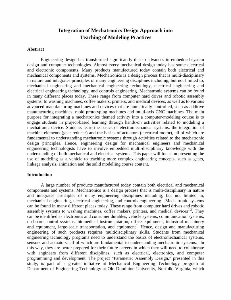
understanding serves as a good basis of how the industrial robots are controlled. They have various degrees of freedom and various electrical motors enabling motion to their linkages. Understanding of polar coordinate systems, and how to define animation in mechanical CAD, is the basis for good understanding of the dynamic structure of a mechatronic system. In addition, creation of linkage analysis in mathematical modeling software GeoGebra8 provides students with a dynamic nature of electromechanical systems and mechatronics. Points on moving linkages and components are not static. Their coordinates are necessary for further control of electro-mechanical and mechatronics systems. Therefore, knowing how to create a dynamic 3D model (animation) is beneficial for future analysis in many ways. Engineers can get important information about collision, location of components during use, and more. Figure 3 shows the elements of the mechatronic design approach that were covered in this class through this project-based learning activity through the computer solid modelling experience.
Figure 3: Mechatronics design approach integration into Computer Solid Modeling
The core skill development given to students through this project was computer solid modeling. This project included various other layers of instruction, such as mechatronics; gears, standard parts, planar linkage mechanisms, animation, and design verification (Figure 4).
Figure 4: Different facets of instructions of computer solid modelling with mechatronics
methodology
Gears Standard parts Mechanisms Animation Verification
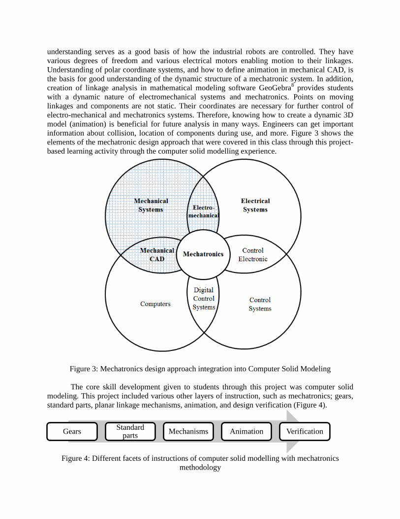
Gears are one of the most important machine elements. At Universities A and B, machine elements are not taken in the freshman year because they require successfully completed courses such as Statics, Strength of Materials, and Calculus I. In this project students get exposed to different parameters that are needed for a gear design and they are required to model six different gears. An example of gears submitted by students is given in Figure 5.
Figure 5: Example gears submitted by students (G2 – left, G3 – right)
Standard parts are the parts that can be purchased and do not need to be modeled. Students learned how to generate standard parts from a catalog (Content Center) in CAD software used in this project (Autodesk’s Inventor). They were required to select appropriate standard sizes from given family trees, as shown in Figure 6.
Figure 6: Examples of standard parts used in this assembly submitted by students
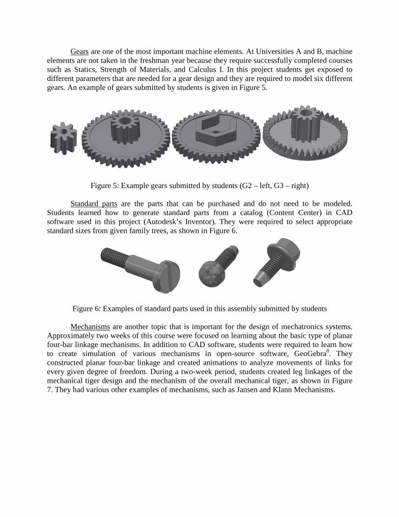
Mechanisms are another topic that is important for the design of mechatronics systems. Approximately two weeks of this course were focused on learning about the basic type of planar four-bar linkage mechanisms. In addition to CAD software, students were required to learn how to create simulation of various mechanisms in open-source software, GeoGebra8. They constructed planar four-bar linkage and created animations to analyze movements of links for every given degree of freedom. During a two-week period, students created leg linkages of the mechanical tiger design and the mechanism of the overall mechanical tiger, as shown in Figure 7. They had various other examples of mechanisms, such as Jansen and Klann Mechanisms.
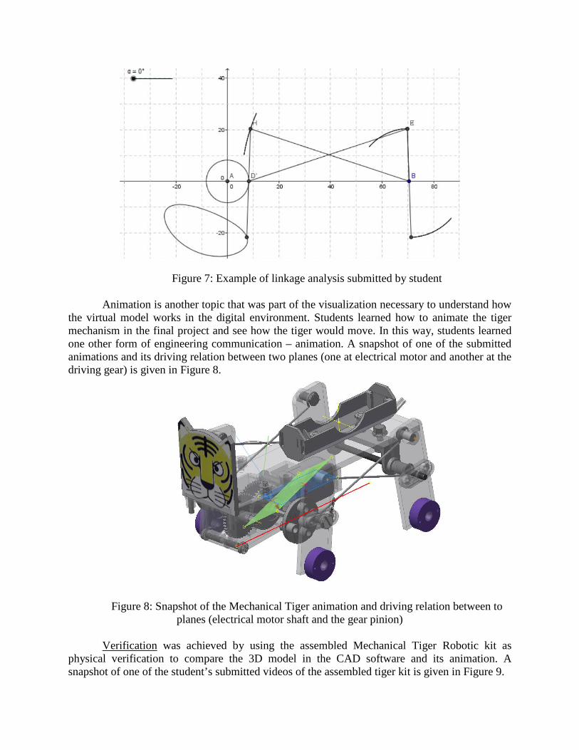
Figure 7: Example of linkage analysis submitted by student
Animation is another topic that was part of the visualization necessary to understand how the virtual model works in the digital environment. Students learned how to animate the tiger mechanism in the final project and see how the tiger would move. In this way, students learned one other form of engineering communication – animation. A snapshot of one of the submitted animations and its driving relation between two planes (one at electrical motor and another at the driving gear) is given in Figure 8.
Figure 8: Snapshot of the Mechanical Tiger animation and driving relation between to planes (electrical motor shaft and the gear pinion)
Verification was achieved by using the assembled Mechanical Tiger Robotic kit as
physical verification to compare the 3D model in the CAD software and its animation. A snapshot of one of the student’s submitted videos of the assembled tiger kit is given in Figure 9.

Figure 9: Movie of Mechanical Tiger kit walking submitted by a student
Online Training Materials for Solid Modeling Course
Supplemental learning materials were created for students during the fall 2013 semester at University A. The YouTube channel included 14 videos in which the professor showed students modeling strategies for modeling the first 13 parts. University B students, enrolled in the fall 2014, had access to this YouTube channel and were given high-resolution videos through an online learning platform. All video materials contained sufficient help, and were actively used by the University B instructor, since it was her first time to teach this class in this CAD software. A snapshot of one tutorial is given in Figure 10.
Figure 10: Tiger Face part tutorial video

Project Implementation The project presented in this paper was first implemented in a course named Computer
Solid Modeling during a Mechanical Engineering Technology program in the fall 2013 at Old Dominion University, Norfolk, Virginia. A similar project under the same name, and with analogous course objectives, was taught during several semesters, starting in the fall 2014, also in the Mechanical Engineering Technology program at Purdue University, Columbus, Indiana. The official course description at Old Dominion University is: “A treatment of modern 3-D parametric solid modeling techniques including introduction of the software utilized sketching, parts and assembly creation techniques, orthographic views extraction and manufacturing drawing generation. Presentations include exploded views and animation.” This course is the second engineering graphic course in the freshman year curriculum in the Mechanical Engineering Technology program. All students who are enrolled in the Mechanical Engineering Technology program are required to take this course. It usually has two sessions, each of which has around thirty students per semester. The official course description at Purdue University is: “This course is an introduction to the graphic language used to communicate design ideas using CAD. Topics include sketching, multi-view drawings, auxiliary views, pictorial views, working drawings, dimensioning practices, and section views.” At Purdue University this course is listed under the Computer Graphics Technology department and named “Introduction to Autodesk Inventor”. The course is required for all Engineering Technology students.
During the course at Old Dominion University, students went over hands-on activities, mostly modeling their parts during the scheduled class time. For Purdue University students, all work had to be completed individually, as well. On the first week of the semester, before starting to work on computers in CAD software, all students were required to manually assemble the Tiger Kit. Students had to show proof that their tigers were able to move. This manual assembly activity was very beneficial, providing visual help and guidance for how the same parts would work in Autodesk Inventor. This prepared them for the final project. The project was organized in a scaffolding way, with everything done during the semester included in the final project and the final assembly and mechanism. Students were required to submit all their parts in the Inventor project folder with all necessary files and as PDF files through the online learning platform, Blackboard. They were required to upload these files as a reply to the instructor’s assignment, posted in the online learning platform. They were allowed to submit multiple submissions. In this way, they could keep all their work in the online learning platform and keep track of their revisions. They were expected to learn how to use the online learning environment and be accountable for their files throughout the semester. Their files would be stored securely in a Blackboard environment. They could access them from any location on or off campus, and not only from the classroom or their Google Drive space. In previous courses, instructors would always find at least one USB during the week. In this way, the online learning environment was also used as file storage, as well as a review mechanism for the professor. They turned in all their homework as compressed folders with all project files, assembly files, part files, related images, video files and PDFs. In addition, the professor could focus on grading things that were not visible through printed drawings, such as good constraining practices (fully or not fully constrained sketches), modeling strategies, and model correctness (by adding material and checking the mass). Another benefit of this kind of submission was to reduce the number of pages printed by students, since there is a printing fee associated with university printers.
In the previous course design, students had separate parts through the whole course and a final project that included a completely separate assembly. They did not have a physical assembly kit included and they did not have lectures about gears and mechanisms included in the curriculum. Although perceived as an easy course, there were various students who would take this course multiple times because they had trouble in keeping up with part modeling. Some of them commented that in this kind of course structure, when they could see where the part they are currently working fits in the larger scale, they were more motivated to complete the course.
Conclusion
The main purpose of this project is to engage students in project-based learning through hands-on activities related to the Computer Solid Modeling of an assembly of a minimum of ten components; in this case seventy-four. The best way to learn engineering graphics concepts and standards is through their application on actual problems, similar to the ones encountered in engineering practice. In this way, students learn the basic rules of assembly modeling, bills of materials, and exploded views, all of which are fundamental to understanding mechanical systems. This project focused on the following outcomes: to develop fully constrained sketches; to learn how to model parts and develop engineering drawings for manufacturing; to present designs by creating new presentation files, create exploded assembly views; and to create assembly drawings, generate bills of materials, create and edit parts list, and create balloons. Hence, using geometric models in this project goes beyond the modeling. It serves as a ground for an introduction to more complex engineering knowledge, such as gears, linkages and animation. Students in this project learned how to design a mechanism in mathematical simulation software and how to create animation by transferring a motion from an electrical motor to the first gear, then to the second, and so on. In this way, they are getting pre-exposed to the design of electromechanical / mechatronics systems. It is necessary to understand how the electrical system couples to the mechanical one and how it behaves during use to successfully control it.
Future Implications
The Mechanical Tiger Project that was implemented in both Universities showed
effectiveness in presenting mechanical, electrical, and computer design sections as a whole process of engineering modeling. In the summer 2015, faculties of Purdue University in the Mechanical Engineering Technology department are planning to present a simplified version of this project to the homeschooled population of middle-school-aged children. This activity will be organized as a summer camp or a seminar, and will teach the students about necessary steps in engineering design. The other target of this summer activity is to attract and introduce homeschooled youth to future engineering careers in State B. Acknowledgement
The implementation of the project-based learning activities in this course were supported
by Old Dominion University’s Frank Batten College of Engineering and Technology’s Dean’s Project-Based Learning Grant – 2013, Old Dominion University, Norfolk, Virginia.

References: [1] Jovanovic, V., Michaeli, J. G., Popescu, O, Moustafa, M. R., Tomovic, M., Verma, A., Lin, C. (2014).
Implementing Mechatronics Design Methodology in Mechanical Engineering Technology Senior Design Projects at the Old Dominion University, Proceedings of ASEE National Conference 2014, June 15-18, Indianapolis, IN.
[2] Jovanovic, V., Tomovic, M., Ncube, L., Djuric, A., Katsioloudis, P., Cuckov, F., “Design for Compliance of Mechatronics Systems in Automotive: Material Tracking and Product Data Management Considerations”, SAE 2014 World Congress & Exhibition, Session: LCA and Sustainable Materials/Manufacturing, Detroit, MI, April 8-10, 2014.
[3] Jovanovic, V., “An Overview of Possible Integration of Green Design Principles into Mechatronic Product Development through Product Lifecycle Management”, 2009 ASME International Manufacturing Science and Engineering Conference (MSEC), Purdue University, West Lafayette, IN, October 2009.
[4] Jovanovic, V., Verma, A., Tomovic, M. M., “Development of Courses in Mechatronics and Mechatronic System Design within the Mechanical Engineering Technology Program”, The 11th Latin American and Caribbean Conference for Engineering and Technology - LACCEI 2013, “Innovation in Engineering, Technology and Education for Competiveness and Prosperity”, Cancun, Mexico, August 14-16, 2013.
[5] Jovanovic, V., Verma, A., Tomovic, M. M., “Developing an Option in Mechatronics System Design within the Mechanical Engineering Technology Program”, 2013 International Forum on Systems and Mechatronics, Guilin, China, July 22-25, 2013
[6] Shih. R. H. (2014). Learning Autodesk Inventor 2014, Modeling, Assembly and Analysis, SDC Publications, Mission, KS.
[7] TamiyaUSA (2014). Mechanical Tiger - Four Legged Walking Type, GeniuSeries - Educational Kits: Robocraft Series, Tamiya America, Inc., Irvine, CA.
[8] GeoGebra Software (2015). International GeoGebra Institute: www.geogebra.org/