integration of offshore wind farm using a hybrid hvdc transmission composed by the pwm...
TRANSCRIPT

IEEE TRANSACTIONS ON ENERGY CONVERSION, VOL. 28, NO. 1, MARCH 2013 125
Integration of Offshore Wind Farm Using a HybridHVDC Transmission Composed by the
PWM Current-Source Converterand Line-Commutated Converter
Raymundo E. Torres-Olguin, Alejandro Garces, Member, IEEE, Marta Molinas, Member, IEEE,and Tore Undeland, Fellow, IEEE
Abstract—This paper investigates the feasibility of the applica-tion of a hybrid HVDC transmission system for the grid integrationof offshore wind farms. The proposed hybrid HVDC consists of apulse width modulated current source converter (PWM-CSC) anda line-commutated converter (LCC). The PWM-CSC is connectedto the offshore wind farm and the LCC connects the onshore grid.The hybrid topology takes advantages from self-commutated con-verters as well as LCCs. On the one hand, LCC-based HVdc is themost mature technology with the lowest power losses and lowestcost. On the other hand, PWM-CSC has the same features that avoltage source converter for offshore applications, i.e., the ability tooperate without an external commutation voltage, reactive powercontrol capability, and a relative small footprint. Moreover, boththe PWM-CSC and the LCC are current source converters andhence the coupling can be effortlessly done. The control design forthe entire system is presented and verified using numerical simu-lations. Simulations are performed using PSCAD/EMTDC underdifferent conditions including changes in the wind speed and acand dc faults.
Index Terms—Current-source converter (CSC), high-voltage dc(HVdc) transmission, line-commutated converter (LCC), offshorewind farm (OWF).
I. INTRODUCTION
H IGH-VOLTAGE dc (HVdc) transmission provides signif-icant advantages over typical ac transmission for the grid
integration of offshore wind farms (OWF) located long distancefrom the shore [1]. Most of the studies about integration of OWFusing HVDC have been focused on the voltage source converter(VSC) technology. VSC uses self-commutated devices whichgives attractive features such as: the independent control of ac-tive and reactive power, the ability to supply passive loads and
Manuscript received April 20, 2012; revised August 22, 2012; accepted Octo-ber 9, 2012. Date of current version February 7, 2013. This work was supportedby the Statkraft Ocean Energy Research Program. Paper no. TEC-00192-2012.
R. E. Torres-Olguin, M. Molinas and T. Undeland are with the Depart-ment of Electric Power Engineering, Norwegian University of Science andTechnology, Trondheim 7491, Norway (e-mail: [email protected];[email protected]; [email protected]).
A. Garces is with the Department of Electric Power Engineering, Universi-dad Tecnologica de Pereira, Pereira 66003, Colombia (e-mail: [email protected]).
Color versions of one or more of the figures in this paper are available onlineat http://ieeexplore.ieee.org.
Digital Object Identifier 10.1109/TEC.2012.2230535
weak grids, and the ability to operate without external commu-tation voltage. Moreover, VSC has a relative small footprint dueto the small size of the harmonic filters [2]–[4].
Although the line-commutated converter (LCC) is the mostwidespread HVdc technology around the world, few studieshave been focused on the application of the current source con-verter (CSC) to integrate OWFs to the main grid [5], [6]. Inparticular for offshore applications, LCC has some limitationswhich include: relative large footprint, which is caused by itslarge ac filters, and the need for an external commutation volt-age for proper operation [4], [5]. However, LCC-based HVdctransmission has attractive features such as the highest powercapability, the lowest power losses, and lowest cost among theHVDC options [7].
Among the CSC are those made with self-commutating de-vices, which is denoted in this study as pulse width modulatedCSC (PWM-CSC) [8]. For the integration of OWF, a PWC-CSCs may have similar features than VSCs. For instance, aPWM-CSC has independent control of the active and reactivepower; it can be operated in weak grids or with passive loads;and it has relative small footprint. Furthermore an additionalfeature, a PWM-CSC has an inherent short-circuit protectioncapability [9].
A PWM-CSC requires semiconductor devices with reversevoltage blocking capability. This can be added to standardinsulated-gate bipolar transistor (IGBT) using a diode at the ex-pense of losses and cost [10], [11]. Another alternative is to usethe new type of semiconductor devices such as reverse block-ing IGBTs (RB-IGBT) or integrated gate commutated thyristors(IGCTs). RB-IGBTs have an intrinsic diode which permits re-verse blocking operation. Nevertheless, the power levels are stilllow for HVdc transmission applications [12]. On the other hand,IGCTs are a promising alternative for PWM-CSCs [13]. IGCTsfor 10 and 6.5 kA have been reported in [14] and [15]. Thesemiconductor structure of an IGCT has low intrinsic induc-tance, thus allowing to shut down the current almost instanta-neously. This new type of semiconductors is typically operatedat medium frequency, i.e., about 500 Hz. However, the switch-ing frequency can be increased up to 40 kHz being only limitedby the thermal losses and the design of the cooling system.
The main objective of this paper is to investigate the fea-sibility of using CSC technologies to grid integrate OWFs. Itis speculated that LCC-based HVdc will continue in operation
0885-8969/$31.00 © 2013 IEEE
126 IEEE TRANSACTIONS ON ENERGY CONVERSION, VOL. 28, NO. 1, MARCH 2013
12-pulseLCC
PWM-CSC
DC cable (T model)
low-frequency filter
high-frequency filter
onshoreAC
offshoreAC
Wind Farm(full converterwith PMSG)
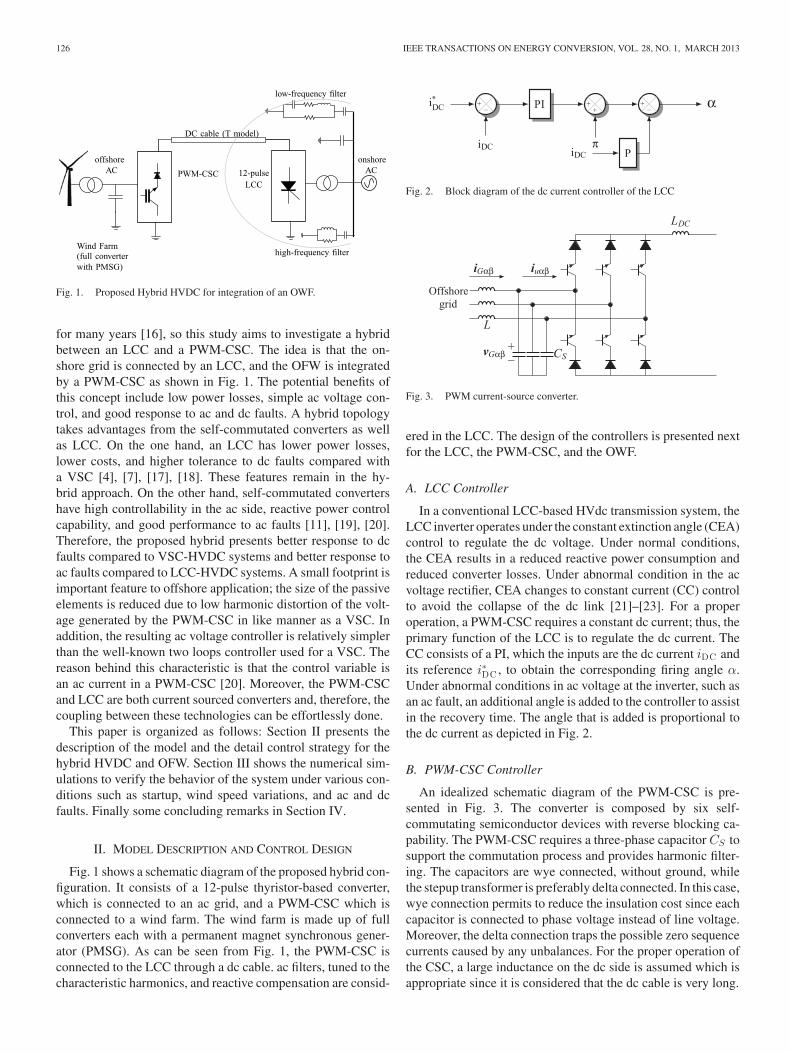
Fig. 1. Proposed Hybrid HVDC for integration of an OWF.
for many years [16], so this study aims to investigate a hybridbetween an LCC and a PWM-CSC. The idea is that the on-shore grid is connected by an LCC, and the OFW is integratedby a PWM-CSC as shown in Fig. 1. The potential benefits ofthis concept include low power losses, simple ac voltage con-trol, and good response to ac and dc faults. A hybrid topologytakes advantages from the self-commutated converters as wellas LCC. On the one hand, an LCC has lower power losses,lower costs, and higher tolerance to dc faults compared witha VSC [4], [7], [17], [18]. These features remain in the hy-brid approach. On the other hand, self-commutated convertershave high controllability in the ac side, reactive power controlcapability, and good performance to ac faults [11], [19], [20].Therefore, the proposed hybrid presents better response to dcfaults compared to VSC-HVDC systems and better response toac faults compared to LCC-HVDC systems. A small footprint isimportant feature to offshore application; the size of the passiveelements is reduced due to low harmonic distortion of the volt-age generated by the PWM-CSC in like manner as a VSC. Inaddition, the resulting ac voltage controller is relatively simplerthan the well-known two loops controller used for a VSC. Thereason behind this characteristic is that the control variable isan ac current in a PWM-CSC [20]. Moreover, the PWM-CSCand LCC are both current sourced converters and, therefore, thecoupling between these technologies can be effortlessly done.
This paper is organized as follows: Section II presents thedescription of the model and the detail control strategy for thehybrid HVDC and OFW. Section III shows the numerical sim-ulations to verify the behavior of the system under various con-ditions such as startup, wind speed variations, and ac and dcfaults. Finally some concluding remarks in Section IV.
II. MODEL DESCRIPTION AND CONTROL DESIGN
Fig. 1 shows a schematic diagram of the proposed hybrid con-figuration. It consists of a 12-pulse thyristor-based converter,which is connected to an ac grid, and a PWM-CSC which isconnected to a wind farm. The wind farm is made up of fullconverters each with a permanent magnet synchronous gener-ator (PMSG). As can be seen from Fig. 1, the PWM-CSC isconnected to the LCC through a dc cable. ac filters, tuned to thecharacteristic harmonics, and reactive compensation are consid-
Fig. 2. Block diagram of the dc current controller of the LCC
Fig. 3. PWM current-source converter.
ered in the LCC. The design of the controllers is presented nextfor the LCC, the PWM-CSC, and the OWF.
A. LCC Controller
In a conventional LCC-based HVdc transmission system, theLCC inverter operates under the constant extinction angle (CEA)control to regulate the dc voltage. Under normal conditions,the CEA results in a reduced reactive power consumption andreduced converter losses. Under abnormal condition in the acvoltage rectifier, CEA changes to constant current (CC) controlto avoid the collapse of the dc link [21]–[23]. For a properoperation, a PWM-CSC requires a constant dc current; thus, theprimary function of the LCC is to regulate the dc current. TheCC consists of a PI, which the inputs are the dc current iDC andits reference i∗DC , to obtain the corresponding firing angle α.Under abnormal conditions in ac voltage at the inverter, such asan ac fault, an additional angle is added to the controller to assistin the recovery time. The angle that is added is proportional tothe dc current as depicted in Fig. 2.
B. PWM-CSC Controller
An idealized schematic diagram of the PWM-CSC is pre-sented in Fig. 3. The converter is composed by six self-commutating semiconductor devices with reverse blocking ca-pability. The PWM-CSC requires a three-phase capacitor CS tosupport the commutation process and provides harmonic filter-ing. The capacitors are wye connected, without ground, whilethe stepup transformer is preferably delta connected. In this case,wye connection permits to reduce the insulation cost since eachcapacitor is connected to phase voltage instead of line voltage.Moreover, the delta connection traps the possible zero sequencecurrents caused by any unbalances. For the proper operation ofthe CSC, a large inductance on the dc side is assumed which isappropriate since it is considered that the dc cable is very long.

TORRES-OLGUIN et al.: INTEGRATION OF OFFSHORE WIND FARM USING A HYBRID HVDC TRANSMISSION COMPOSED 127
Fig. 4. Block diagram of the ac voltage controller of the PWM-CSC.
The primary function of the PWM-CSC is to regulate the off-shore grid at desired voltage amplitude and frequency. Offshoreac voltage is regulated in order that the power, that comes fromthe wind turbines, can be automatically transmitted throughthe HVdc. Furthermore, the PWM-CSC is able to provide theneeded reactive power, in contrast with an LCC which is neces-sary to provide reactive power. To facilitate the control design,the system equations is expressed in a fixed reference frame orαβ frame. Thus, the dynamic of the capacitor CS is given by
CSdvGαβ
dt= iGαβ − iuαβ (1)
where vGαβ is a vector which represents the voltages at the inputof the PWM-CSC, iuαβ represents the output current from thePWM-CSC, and iGαβ is the current going to the OWF. Noticethat iuαβ is also the control variable that can be accessed.
The idea behind the controller is to produce a current iuαβ
such that vGαβ goes toward its reference v∗Gαβ as the time
t goes to infinity, i.e., vGαβ → v∗Gαβ as t → ∞. By defining
vGαβ = v∗Gαβ − vGαβ as the state variable, (1) can be rewritten
as
CSdvGαβ
dt= − (iGαβ − iuαβ ) + CS
d
dtv∗
Gαβ . (2)
The control objective can be reformulated using v∗Gαβ , so
vGαβ goes to zero as the time t goes to infinity, that is vGαβ → 0as t → ∞. To achieve the objective is proposed to calculate iuαβ
as follows:
iuαβ = −Kpv∗Gαβ + CS
dv∗Gαβ
dt+ iGαβ (3)
where Kp is a design parameter matrix. The system (1) in closedloop with the controller (3) yields the following error system:
CSdvGαβ
dt= −Kp vGαβ . (4)
Hence, the control above guarantees stable exponentiallytracking of vGαβ toward v∗
Gαβ . The block diagram is shownin Fig. 4. The reference v∗
Gαβ is a three-phase signal that con-tains both magnitude and frequency that will be imposed onthe offshore side by the PWM-CSC. As can be seen in (3), thecontroller requires the derivative of vGαβ . The calculation of aderivative is highly sensitive to noise. However, in this case thederivative of the error is not calculated but the derivative of thereference signal which is a pure sinusoidal waveform; hence,there is no possibility to amplify noise. The modulation tech-nique used in this paper is space vector [24]. It is noteworthythat the proposed voltage control uses a single- control loop,i.e., the ac voltage is controlled directly. In contrast to a VSCthat needs at least two control loops. This makes the resulting
Fig. 5. Rotor-speed wind characteristic.
control faster in its dynamic response and simpler to implementthan any control used in a VSC.
C. Model of the Offshore Wind Farm
The interaction between the OWF and the hybrid HVdc isstudied using an aggregate model, which consists of simulatingthe behavior of an entire wind farm by using only a single unit.Aggregate model makes some assumptions: 1) the variationsin wind speed are small throughout the wind farm, so wakeeffect is discarded. 2) The shaft is modeled as one-mass model.It is possible to neglect the oscillations of the shaft due thedecoupling between the rotor and the grid produced by the powerelectronic interface. 3) A single-generator model can be madeby summing all the generator of the wind farm. The scalingcan be easily done since the parameters of the generator andconverter are given in per unit.
Aggregate turbine is equipped with two back-to-back IGBTconverter and a PMSG. The controller design of the turbine canbe divided into three parts: the pitch controller, the generator sidecontrolller (GSC) and the ac grid side controller (ACGC). Thepitch controller limits the rotor speed in high-wind conditions,the GSC controls the rotor speed to achieve the maximum powerat low-wind conditions and, the ACGS regulates the dc-linkvoltage for the proper operation of the back-to-back converter.More details about each part of the turbine controller are givennext.
1) Pitch Controller: If the turbine is operating above therated wind speed, the actuator system must change the pitchangle, and thus, reduce the power coefficient Cp . ModifyingCp , it can keep the turbine operating at a rated power, and avoidoverloading and damage both the generator and converter [25].This study uses the controller presented in [26].
2) Generator Side Controller: The GSC is based on thesteady-state characteristic of the wind turbine, the type con-sidered here, is a typical three-blade horizontal-axis design. Toillustrate the mechanism, Fig. 5 shows the output mechanicalpower versus the rotor speed ω in the turbine without pitchcontrol action. As can be seen from Fig. 5, for a given rotorspeed, and for each wind speed, there is a point of maximumpower. Optimal efficiency line results of connecting all pointsof maximum power. The objective of the GSC is to extract the
128 IEEE TRANSACTIONS ON ENERGY CONVERSION, VOL. 28, NO. 1, MARCH 2013
+_
PMSG
iS dq iGdq
uGdq vGdq
LG
uS dqvDC
β
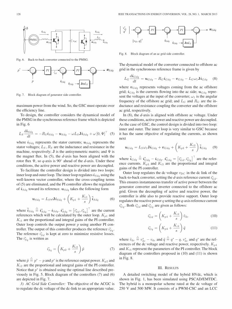
Fig. 6. Back-to-back converter connected to the PMSG.
Fig. 7. Block diagram of generator side controller.
maximum power from the wind. So, the GSC must operate overthe efficiency line.
To design, the controller considers the dynamical model ofthe PMSG in the synchronous reference frame which is depictedin Fig. 6
LSdiSdq
dt= −RS iSdq − uSdq − ωLSJiSdq + ω [0,Ψ]� (5)
where iSdq represents the stator currents; uSdq represents thestator voltages; LS ,RS are the inductance and resistance in themachine, respectively; J is the antisymmetric matrix; and Ψ isthe magnet flux. In (5), the d-axis has been aligned with therotor flux Ψ, so q-axis is 90◦ ahead of the d-axis. Under theseconditions, the active power and reactive power are decoupled.
To facilitate the controller design is divided into two loops:inner loop and outer loop. The inner loop regulates iSdq using thewell-known vector controller, where the cross-coupling termsof (5) are eliminated, and the PI controller allows the regulationof iSdq toward its reference. uSdq takes the following form
uSdq = LS ωJiSdq +(
Kp1 +Ki1
s
)iSdq (6)
where iSdq�= i∗Sdq − iSdq . i∗Sdq =
[i∗Sd , i
∗Sq
]�are the current
references which will be calculated by the outer loop. Kp1 andKi1 are the proportional and integral gains of the PI controller.Outer loop controls the output power p using another PI con-troller. The output of this controller produces the reference i∗Sq .The reference i∗Sd is kept at zero to minimize resistive losses.The i∗Sq is written as
i∗Sq =(
Kp2 +Ki2
s
)p (7)
where p�= p∗ − p and p∗ is the reference output power. Kp2 and
Ki2 are the proportional and integral gains of the PI controller.Notice that p∗ is obtained using the optimal line described pre-viously in Fig. 5. Block diagram of the controllers (7) and (6)are depicted in Fig. 7.
3) AC Grid Side Controller: The objective of the ACGC isto regulate the dc voltage of the dc-link to an appropriate value.
Fig. 8. Block diagram of an ac grid side controller.
The dynamical model of the converter connected to offshore acgrid in the synchronous reference frame is given by
LGdiGdq
dt= uGdq − RG iGdq − vGdq − LGω1JiGdq (8)
where vGdq represents voltages coming from the ac offshoregrid; iGdq is the currents flowing into the ac side; uGdq repre-sent the voltages at the input of the converter; ω1 is the angularfrequency of the offshore ac grid; and LG and RG are the in-ductance and resistance coupling the converter and the offshoreac grid, respectively.
In (8), the d-axis is aligned with offshore ac voltage. Underthese conditions, active power and reactive power are decoupled.As the case of GSC, the control design is divided into two loop:inner and outer. The inner loop is very similar to GSC becauseit has the same objective of regulating the currents, as shownnext
uGdq = LS ω1JiGdq + vGdq +(
Kp3 +Ki3
s
)iGdq (9)
where iGdq�= i∗Gdq − iGdq . i∗Gdq =
[i∗Gd, i
∗Gq
]�are the refer-
ence currents. Kp3 and Ki3 are the proportional and integralgains of the PI controller.
Outer loop regulates the dc voltage vDC in the dc link of theback-to-back converter, setting the d-axis reference current i∗Gd .This ensures instantaneous transfer of active power between thegenerator converter and inverter connected to the offshore acgrid. Given the decoupling of active and reactive power, thecontroller is able also to provide reactive support. Outer loopregulates the reactive power q setting the q-axis reference currenti∗Gq . Both i∗Gd and i∗Gq are given as follows:
i∗Gd =(
Kp4 +Ki4
s
)vdc (10)
i∗Gq =(
Kp4 +Ki4
s
)q (11)
where vdc�= v∗
dc − vdc and q�= q∗ − q. v∗
dc and q∗ are the ref-erences of the dc voltage and reactive power, respectively. Kp4and Ki4 represent the parameters of the PI controller. The blockdiagram of the controllers proposed in (10) and (11) is shownin Fig. 8.
III. RESULTS
A detailed switching model of the hybrid HVdc, which isshown in Fig. 1, has been simulated using PSCAD/EMTDC.The hybrid is a monopolar scheme rated at the dc voltage of250 V and 500 MW. It consists of a PWM-CSC and an LCC

TORRES-OLGUIN et al.: INTEGRATION OF OFFSHORE WIND FARM USING A HYBRID HVDC TRANSMISSION COMPOSED 129
through a dc transmission line of 100 km. The inverter is a12-pulse thyristor-based converter connected to an ac source of345 kV. The inverter contains a set of three passive filters whoseparameters have been obtained from the CIGRE benchmark butscaled to 500 MW [27].
The PWM-CSC is connected to the offshore grid using a ca-pacitive filter CS of 6 μF together with a step-down transformer.The average switching frequency of the PWM-CSC is 2 kHz.The dc line and the smoothing reactors are modeled using aT-model the parameters have been obtain from [27]. The windfarm is simulated as a single unit of the 500 MW full converterturbine with PMSG. The switching frequency of the converteris 2 kHz. The phase reactor is selected 0.15 p.u., and the dccapacitor is calculated using a time constant of 5 ms. The Ap-pendix lists the most important parameters of the PMSG. Toinvestigate the characteristics of the system, as well as the per-formance of the proposed control strategy, several simulationshave been performed under different operating conditions suchas the startup, the response to change of wind speed, and theresponse to failures of both ac and dc faults.
A. Startup
Fig. 9 shows the start-up transient. At t = 0.05 s LCC isenabled, dc currents at the PWM-CSC and the LCC begin toincrease from 0 to its nominal value as is shown in Fig. 9(b).Once the dc current has reached the nominal value at t = 0.15 s,the PWM-CSC is enabled and the offshore ac voltage is rampedup to its nominal value as is depicted in Fig. 9(a). At this time, theOWF is disabled, and the ac offshore grid is operated in islandmode, with a fixed amplitude voltage and frequency. Frequencyis kept at 50 Hz. Once the nominal offshore ac voltage is reachedat t = 0.3 s, the ACGC is enabled and synchronized with theoffshore ac voltage. Once synchronized, the dc link of eachturbine is able to be charged. At t = 0.4 s, the GSC is enabledand the output power starts to increase automatically as is seenin Fig. 9(d). Also Fig. 9(c) shows variations in the dc voltageand and Fig. 9(e) shows the reactive power at the PWM-CSCand LCC, respectively.
B. Response to Change in Wind Speed
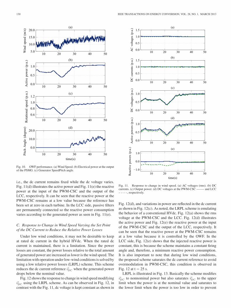
To study the interaction between hybrid HVdc and an OWF,an aggregate model of the turbine has been implemented. Thismodel is aimed to reduce the simulation time without losing ac-curacy [28]. Fig. 10 shows the performance of the OWF underdifferent wind-speed conditions [25]. These conditions are sum-marized as follows: at first, the wind speed is below the nominal,i.e., from t = 0 s to t = 15 s, the wind speed vw is 10 m/s. Thenominal wind speed is vw = 12 m/s. Then, at t = 10 s a rampbegins that increases vw at a rate of 4 m/s in 30 s. Then, at t =15 s a wind speed gust occurs which decreases vw amplitude3 m/s with 10 s of duration. Finally, the wind speed is abovenominal, that is vw = 15 m/s. Fig. 10(a) depicts the wind pro-file described previously, throughout the simulation the wind isnoisy. Noise wind data are the following: number of noise com-ponent 250, random seed number 50, time interval for randomgeneration 0.35 s, and noise amplitude controlling parameter 10
Fig. 9. Response during start up of the hybrid HVdc. (a) AC voltages (rms).(b) DC current. (c) DC voltages. (d) Active power at the PWM-CSC —- andLCC - - - -, respectively.
rad/s [29]. Fig. 10(b) shows the output power from the OWFand Fig. 10(c) shows the generator speed. Fig. 10(d) shows thepitch angle. As noted, when the wind is below the nominal windspeed, the turbine operates in the maximum power point track-ing mode. Once the nominal wind speed is exceeded, the pitchangle controller is enabled and power extracted from the windturbine is limited to the nominal value.
Fig. 11 shows the response to the wind condition describedpreviously. Fig. 11(a) shows the rms voltage at the PWM-CSCand the LCC, as can be seen both voltages are at their nominalvalues. Fig. 11(b) depicts dc currents at the output of the PWM-CSC and the input of the LCC. As it can be seen the dc current isregulated successfully by the LCC using the strategy describedin Fig. 2. Fig. 11(c) shows how the dc voltage varies when thepower generated by the OWF changes. It should be noted thatthe proposed hybrid works in reverse to a conventional HVdc,
130 IEEE TRANSACTIONS ON ENERGY CONVERSION, VOL. 28, NO. 1, MARCH 2013
Fig. 10. OWF performance. (a) Wind Speed. (b) Electrical power at the outputof the PSMG. (c) Generator SpeedPitch angle.
i.e., the dc current remains fixed while the dc voltage varies.Fig. 11(d) illustrates the active power and Fig. 11(e) the reactivepower at the input of the PWM-CSC and the output of theLCC, respectively. It can be seen that the reactive power at thePWM-CSC remains at a low value because the reference hasbeen set at zero in each turbine. In the LCC side, passive filtersare permanently connected so the reactive power consumptionvaries according to the generated power as seen in Fig. 11(e).
C. Response to Change in Wind Speed Varying the Set Pointof the DC Current to Reduce the Relative Power Losses
Under low wind conditions, it may not be desirable to keepat rated dc current in the hybrid HVdc. When the rated dccurrent is maintained, there is a limitation. Since the powerlosses are constant, the power losses relative to the total amountof generated power are increased as lower is the wind speed. Thelimitation with operation under low-wind conditions is solved byusing a low relative power losses (LRPL) scheme. This schemereduces the dc current reference i∗DC when the generated powerdrops below the nominal value.
Fig. 12 shows the response to change in wind speed modifyingi∗DC using the LRPL scheme. As can be observed in Fig. 12, incontrast with the Fig. 11, dc voltage is kept constant as shown in
Fig. 11. Response to change in wind speed. (a) AC voltages (rms). (b) DCcurrents. (c) Output power. (d) DC voltages at the PWM-CSC ——– and LCC– – – –, respectively.
Fig. 12(d), and variations in power are reflected in the dc currentas shown in Fig. 12(c). As noted, the LRPL scheme is emulatingthe behavior of a conventional HVdc. Fig. 12(a) shows the rmsvoltage at the PWM-CSC and the LCC. Fig. 12(d) illustratesthe active power and Fig. 12(e) the reactive power at the inputof the PWM-CSC and the output of the LCC, respectively. Itcan be seen that the reactive power at the PWM-CSC remainsat a low value because it is controlled by the OWF. In theLCC side, Fig. 12(e) shows that the injected reactive power isconstant, this is because the scheme maintains a constant firingangle and, therefore, a minimum reactive power consumption.It is also important to note that during low wind conditions,the proposed scheme saturates the dc current reference to avoidovermodulation in PWM-CSC, this condition is observed inFig. 12 at t = 25 s.
LRPL is illustrated in Fig. 13. Basically the scheme modifiesi∗DC to nonnominal power but also saturates i∗DC to the upperlimit when the power is at the nominal value and saturates tothe lower limit when the power is too low in order to prevent

TORRES-OLGUIN et al.: INTEGRATION OF OFFSHORE WIND FARM USING A HYBRID HVDC TRANSMISSION COMPOSED 131
Fig. 12. Response to change in wind speed. (a) AC voltages (rms). (b) DCcurrents. (c) Output power. (d) DC voltages at the PWM-CSC ——- and LCC– – – –, respectively.
Fig. 13. Low relative power losses scheme.
overmodulation at the PWM-CSC. Fig. 14 shows the relativepower losses with and without the proposed LRPL scheme. Atnominal power the relative power losses are the same with or
Fig. 14. Power losses relative to the total amount of generated power.
6.4 6.5 6.6 6.7 6.8 6.9 7−0.5
0.0
0.5
1.0
1.5
AC
volt
ages
(p.u
.) (a)
6.4 6.5 6.6 6.7 6.8 6.9 70.0
2.0
4.0
DC
curr
ents
(p.u
.)
(b)
6.4 6.5 6.6 6.7 6.8 6.9 7−1.0
0.0
1.0
DC
volt
ages
(p.u
.) (c)
6.4 6.5 6.6 6.7 6.8 6.9 7
−1.0
0.0
1.0
2.0
Act
ive
pow
ers
(p.u
.) (d)
6.4 6.5 6.6 6.7 6.8 6.9 7−2.0
−1.0
0.0
1.0
time(s)
Rea
ctiv
epo
wer
s(p
.u.) (e)
Fig. 15. Response to three-phase to ground fault at the LCC. (a) AC voltages(rms). (b) DC currents. (c) Output power. (d) DC voltages at the PWM-CSC—— and LCC – – – –, respectively.
without the LRPL scheme, but there is a significant reductionwhen the power extracted by the turbine is less than the nominal.
D. Response to Faults
The response of the hybrid HVdc to three-phase to groundfault at the LCC is shown in Fig. 15. The fault was appliedat t = 6.5 s and was cleared after 100 ms. Fig. 15(a) depictsthe rapid drop of the ac voltage caused by the fault. As can beseen from Fig. 15(b), the dc current has an abrupt rise because
132 IEEE TRANSACTIONS ON ENERGY CONVERSION, VOL. 28, NO. 1, MARCH 2013
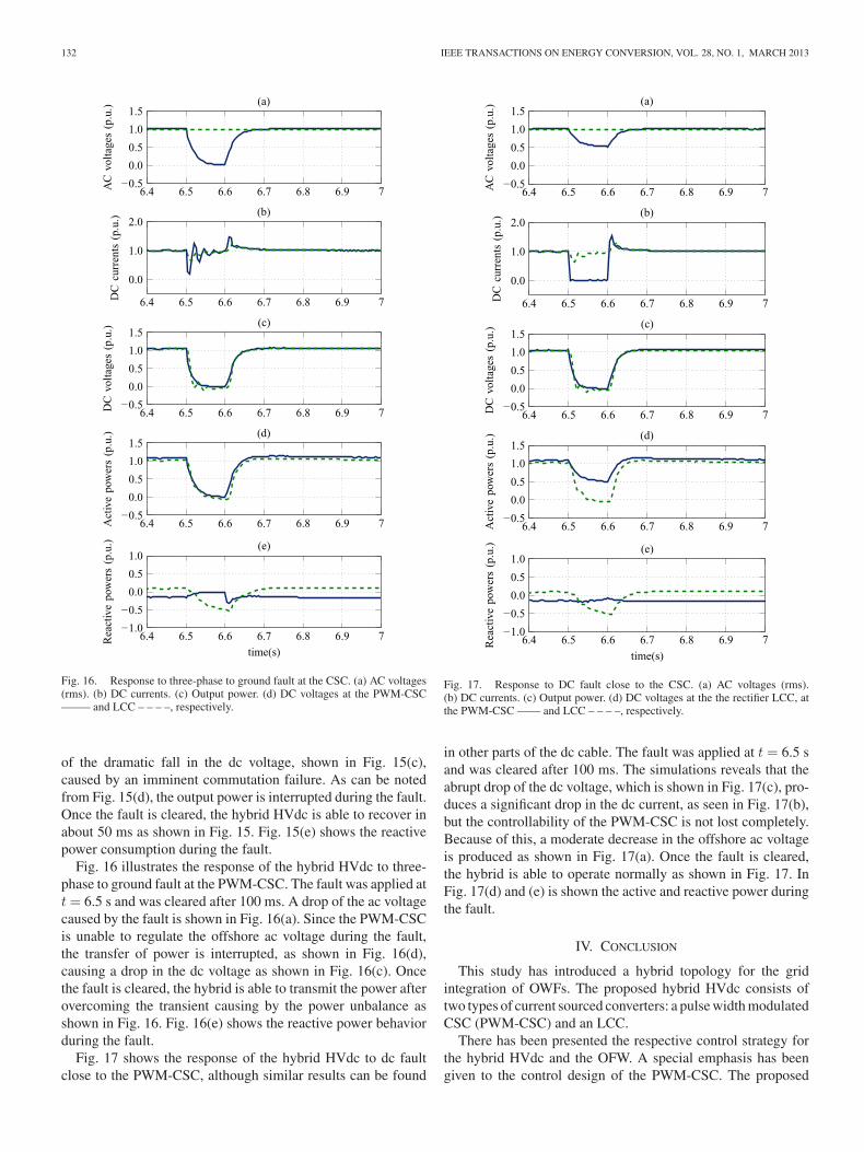
Fig. 16. Response to three-phase to ground fault at the CSC. (a) AC voltages(rms). (b) DC currents. (c) Output power. (d) DC voltages at the PWM-CSC——– and LCC – – – –, respectively.
of the dramatic fall in the dc voltage, shown in Fig. 15(c),caused by an imminent commutation failure. As can be notedfrom Fig. 15(d), the output power is interrupted during the fault.Once the fault is cleared, the hybrid HVdc is able to recover inabout 50 ms as shown in Fig. 15. Fig. 15(e) shows the reactivepower consumption during the fault.
Fig. 16 illustrates the response of the hybrid HVdc to three-phase to ground fault at the PWM-CSC. The fault was applied att = 6.5 s and was cleared after 100 ms. A drop of the ac voltagecaused by the fault is shown in Fig. 16(a). Since the PWM-CSCis unable to regulate the offshore ac voltage during the fault,the transfer of power is interrupted, as shown in Fig. 16(d),causing a drop in the dc voltage as shown in Fig. 16(c). Oncethe fault is cleared, the hybrid is able to transmit the power afterovercoming the transient causing by the power unbalance asshown in Fig. 16. Fig. 16(e) shows the reactive power behaviorduring the fault.
Fig. 17 shows the response of the hybrid HVdc to dc faultclose to the PWM-CSC, although similar results can be found
Fig. 17. Response to DC fault close to the CSC. (a) AC voltages (rms).(b) DC currents. (c) Output power. (d) DC voltages at the the rectifier LCC, atthe PWM-CSC —— and LCC – – – –, respectively.
in other parts of the dc cable. The fault was applied at t = 6.5 sand was cleared after 100 ms. The simulations reveals that theabrupt drop of the dc voltage, which is shown in Fig. 17(c), pro-duces a significant drop in the dc current, as seen in Fig. 17(b),but the controllability of the PWM-CSC is not lost completely.Because of this, a moderate decrease in the offshore ac voltageis produced as shown in Fig. 17(a). Once the fault is cleared,the hybrid is able to operate normally as shown in Fig. 17. InFig. 17(d) and (e) is shown the active and reactive power duringthe fault.
IV. CONCLUSION
This study has introduced a hybrid topology for the gridintegration of OWFs. The proposed hybrid HVdc consists oftwo types of current sourced converters: a pulse width modulatedCSC (PWM-CSC) and an LCC.
There has been presented the respective control strategy forthe hybrid HVdc and the OFW. A special emphasis has beengiven to the control design of the PWM-CSC. The proposed

TORRES-OLGUIN et al.: INTEGRATION OF OFFSHORE WIND FARM USING A HYBRID HVDC TRANSMISSION COMPOSED 133
controller can control the offshore ac voltage and provide thenecessary reactive power. Furthermore, ac voltage controllerneeds only one control loop because the control variable is theac current flowing to the converter. Therefore, PWM-CSC con-troller results simple to implement. Moreover, it was proved thatthe proposed hybrid can operate successfully in island mode, soit has a self-start capability.
It was shown that hybrid HVdc under low wind conditionshas a limitation when the dc current is maintained at nominalvalue. Since the power losses are constant, the power lossesrelative to the total amount of generated power are increased aslower is the wind speed. To overcome this limitation an LRPLscheme has been proposed. This scheme aims to reduce the dccurrent reference at low wind conditions in order to minimizethe relative power losses. Furthermore, it is essential to makethe OFW to provide active power support as a conventionalpower plant. The OWFs require information from onshore acfrequency in order to participate in the active power support. Acommunication-free scheme may be challenging for this hybridHVdc, if minimal power losses and frequency support schemesare considered at the same time. In the case of fast communica-tion scheme, a similar behavior between hybrid and VSC-basedHVdc would be expected.
Based on simulations, it has been proven that hybrid HVdcperforms satisfactory under various operation conditions includ-ing wind speed variations and ac and dc faults. AC faults weretested both at LCC and at PWM-CSC, and it was found that thesystem is able to tolerate such faults. DC fault was also simu-lated and the results showed that the impact is not as significantas a VSC-based HVdc. In summary, this paper has presented ahybrid option which is a convenient alternative to combine thetechnologies of current source converters in the integration ofOWFs.
APPENDIX
Wind FarmParameters Values UnitsRated Power 500 MWRated Voltage 0.69 kVLS d 0.5 p.u.LS q 0.51 p.u.RS 0.01 p.u.Magnet Flux 1.2 p.u.Inertia constant 3 sConverter transformersParameters Values UnitsRated Power 500 MWVoltage ratio (onshore) 345/212 kVleakage reactance(onshore) 0.18 puVoltage ratio (offshore) 500/0.69 kVleakage reactance(offshore) 0.15 pu
REFERENCES
[1] N. Kirby, L. Xu, M. Luckett, and W. Siepmann, “Hvdc transmission forlarge offshore wind farms,” Power Eng. J., vol. 16, no. 3, pp. 135–141,Jun. 2002.
[2] L. Zhang, L. Harnefors, and H.-P. Nee, “Modeling and control of VSC-HVdc links connected to island systems,” IEEE Trans. Power Syst., vol. 26,no. 2, pp. 783–793, May 2011.
[3] C. Feltes, H. Wrede, F. Koch, and I. Erlich, “Enhanced fault ride-throughmethod for wind farms connected to the grid through VSC-based HVdctransmission,” IEEE Trans. Power Syst., vol. 24, no. 3, pp. 1537–1546,Aug. 2009.
[4] L. Xu and B. Andersen, “Grid connection of large offshore wind farmsusing hvdc,” Wind Energy, vol. 9, no. 4, pp. 371–382, 2006.
[5] S. Bozhko, R. Blasco-Gimenez, R. Li, J. Clare, and G. Asher, “Controlof offshore DFIG-based wind farm grid with line-commutated HVdc con-nection,” IEEE Trans. Energy Convers., vol. 22, no. 1, pp. 71–78, Mar.2007.
[6] R. Li, S. Bozhko, and G. Asher, “Frequency control design for offshorewind farm grid with LCC-HVdc link connection,” IEEE Trans. PowerElectron., vol. 23, no. 3, pp. 1085–1092, May 2008.
[7] N. Negra, J. Todorovic, and T. Ackermann, “Loss evaluation of HVac andHVdc transmission solutions for large offshore wind farms,” Electr. PowerSyst. Res., vol. 76, no. 11, pp. 916–927, 2006.
[8] E. Wiechmann, P. Aqueveque, R. Burgos, and J. Rodriguez, “On theefficiency of voltage source and current source inverters for high-powerdrives,” IEEE Trans. Ind. Electron., vol. 55, no. 4, pp. 1771–1782, Apr.2008.
[9] Z. Bai, Z. Zhang, and X. Ruan, “A natural soft-commutation PWM schemefor current source converter and its logic implementation,” IEEE Trans.Ind. Electron., vol. 58, no. 7, pp. 2772–2779, Jul. 2011.
[10] Y. Ye, M. Kazerani, and V. Quintana, “Current-source converter basedstatcom: Modeling and control,” IEEE Trans. Power Del., vol. 20, no. 2,pp. 795–800, Apr. 2005.
[11] N. Stretch, M. Kazerani, and R. El Shatshat, “A current-sourced converter-based HVdc light transmission system,” in Proc. IEEE Int. Symp. Ind.Electron., Jul. 2006, vol. 3, pp. 2001–2006.
[12] C. Klumpner and F. Blaabjerg, “Using reverse blocking IGBTS in powerconverters for adjustable speed drives,” IEEE Trans. Ind. Appl., vol. 42,no. 3, pp. 807–816, May/Jun. 2006.
[13] T. Modeer, H. Nee, and S. Norrga, “Loss comparison of different sub-module implementations for modular multilevel converters in HVdc ap-plications,” in Proc. 14th Eur. Conf. Power Electron. Appl., Aug./Sep.2005, pp. 1–7.
[14] P. Steimer, O. Apeldoorn, B. Odegard, S. Bernet, and T. Bruckner, “Veryhigh power IGCT PEBB technology,” in Proc. IEEE 36th Power Electron.Special. Conf., Jun. 2005, pp. 1–7.
[15] Y. Suh and P. Steimer, “Application of IGCT in high-power recti-fiers,” IEEE Trans. Ind. Appl., vol. 45, no. 5, pp. 1628–1636, Sept./Oct.2009.
[16] L. Carlsson, “Classical HVdc: Still continuing to evolve,” Modern PowerSyst., vol. 22, no. 6, pp. 19–22, 2002.
[17] H. Zhou, G. Yang, and J. Wang, “Modeling, analysis, and control for therectifier of hybrid HVDC systems for DFIG-based wind farms,” IEEETrans. Energ. Convers., vol. 26, no. 1, pp. 340–353, Mar. 2011.
[18] C. Guo, Y. Zhang, A. Gole, and C. Zhao, “Analysis of dual-infeed hvdcwith LCC–HVdc and VSC–HVdc,” IEEE Trans. Power Del., vol. 27,no. 3, pp. 1529–1537, Jul. 2012.
[19] B. Andersen, L. Xu, and K. Wong, “Topologies for vsc transmission,”in Proc. 7th Int. Conf. AC-DC Power Transmiss., Nov. 2001, pp. 298–304.
[20] Y. Ye, M. Kazerani, and V. Quintana, “Modeling, control and imple-mentation of three-phase pwm converters,” IEEE Trans. Power Electron.,vol. 18, no. 3, pp. 857–864, May 2003.
[21] K. Padiyar, Power System Dynamics. New York: Wiley, 2008.[22] E. Kimbark, Direct Current Transmission. New York: Wiley-
Interscience, 1971, vol. 1.[23] J. Arrillaga, High Voltage Direct Current Transmission. London, U.K.:
IET, 1998, vol. 29.[24] Y. W. Li, B. Wu, D. Xu, and N. Zargari, “Space vector sequence investiga-
tion and synchronization methods for PWM modulation of a high powercurrent source rectifier,” in Proc. IEEE Power Electron. Special. Conf.,Jun. 2007, pp. 2841–2847.
[25] J. Slootweg, S. De Haan, H. Polinder, and W. Kling, “General modelfor representing variable speed wind turbines in power system dynamicssimulations,” IEEE Trans. Power Syst., vol. 18, no. 1, pp. 144–151, Feb.2003.
[26] J. Zhang, M. Cheng, Z. Chen, and X. Fu, “Pitch angle control for variablespeed wind turbines,” in Proc. 3rd IEEE Int. Conf. Electr. Utility Deregul.Restruct. Power Technol., Apr. 2008, pp. 2691–2696.
[27] M. Szechtman, T. Wess, and C. Thio, “A benchmark model for HVdcsystem studies,” in Proc. Int. Conf. AC-DC Power Transmiss., Sep. 1991,pp. 374–378.

134 IEEE TRANSACTIONS ON ENERGY CONVERSION, VOL. 28, NO. 1, MARCH 2013
[28] J. Conroy and R. Watson, “Aggregate modelling of wind farms con-taining full-converter wind turbine generators with permanent magnetsynchronous machines: Transient stability studies,” Renewable PowerGenerat. IET, vol. 3, no. 1, pp. 39–52, Mar. 2009.
[29] P. Anderson and A. Bose, “Stability simulation of wind turbine systems,”IEEE Trans. Power Apparat. Syst., vol. PAS-102, no. 12, pp. 3791–3795,Dec. 1983.
Raymundo E. Torres-Olguin received the B.Sc. de-gree in electromechanical engineering from the Uni-versity of San Luis Potosi, Mexico, in 2004, and theM.Sc. degree in control and dynamic systems fromthe Applied Mathematics Department, Research In-stitute of Science and Technology, San Luis Potosi(IPICYT), in 2006. He is currently working towardthe Ph.D. degree in electrical power engineering atthe Norwegian University of Science and Technol-ogy, (NTNU), Trondheim, Norway since 2008.
From 2006 to 2008, he was a Technical Assistantin the Laboratory of Processing and Quality of Energy, IPICYT. He is cur-rently working as Research Scientist in SINTEF Energy Research. His mainresearch interest includes modeling and control of power electronics for renew-able sources especially wind power systems.
Mr. Torres-Olguin contributes as a Reviewer for the IEEE TRANSACTIONS
ON INDUSTRIAL ELECTRONICS, the IEEE TRANSACTIONS ON POWER DELIVERY,and the IEEE TRANSACTIONS ON POWER ELECTRONICS.
Alejandro Garces (M’04) received the Bachelor de-gree in electrical engineering and the Master degreein power system planning both from the Universi-dad Tecnologica de Pereira, Pereira, Colombia. Hereceived the Ph.D. degree from the Norwegian Uni-versity of Science and Technology, Trondheim, Nor-way, in 2012.
He is currently a Professor at the Universidad Tec-nologica de Pereira. His research interests includepower electronics, power system optimization, re-newable energies, and HVdc transmission.
Marta Molinas (M’94) received the Diploma inelectro-mechanical engineering from the NationalUniversity of Asuncion, Asuncion, Paraguay, in1992, the M.Sc. degree from Ryukyu University, Ok-inawa, Japan, in 1997, and the Dr. Eng. degree fromTokyo Institute of Technology, Tokyo, Japan, in 2000.
She was a Guest Researcher with the University ofPadova, Padova, Italy. From 2004 to 2007, she was aPostdoctoral Researcher with the Norwegian Univer-sity of Science and Technology, Trondheim, Norway,where she has been a Professor since 2008. From
2008 to 2009, she was a JSPS Research Fellow with the Energy TechnologyResearch Institute of Advanced Industrial Science and Technology, Tsukuba,Japan. Her research interests include wind/wave energy conversion systems,and power electronics and electrical machines in distributed energy systems.
Dr. Molinas is an AdCom member of the IEEE Power Electronics Society.She is an active Reviewer for the IEEE TRANSACTIONS ON INDUSTRIAL ELEC-TRONICS and the IEEE TRANSACTIONS ON POWER ELECTRONICS.
Tore Undeland (M’86–SM’92–F’00) received theM.Sc. and Ph.D. degrees from the Norwegian Uni-versity of Science and Technology (NTNU), Trond-heim, Norway, in 1970 and 1977, respectively.
Since 1984, he has been a Professor in powerelectronics at the Department of Electric Power En-gineering, NTNU. He is devoted to teaching and is acoauthor of the textbook Power Electronics (Wiley).He has published more than 100 papers. His researchinterests include new converters for UPS, Inductionheating, SMPS, PV, and Wind energy.
Dr. Undeland was the Chairman of the European Conference on Power Elec-tronics and Applications (EPE) 97 in Trondheim and later on the President ofthe EPE.