integration of reusable software components and - citeseer
TRANSCRIPT
VISUAL SOFTWARE CONSTRUCTION APPROACH 863
Received September 11, 1998; revised April 14, 1999; accepted May 21, 1999.Communicated by Y. S. Kuo.* This research work was supported in part by the National Science Council, Taiwan, under contractlog#34102F. An earlier version of this paper was presented at the 13th International Conference onAdvanced Science and Technology, 1997.
JOURNAL OF INFORMATION SCIENCE AND ENGINEERING 16, 863-884 (2000)
863
Integration of Reusable Software Componentsand Frameworks Into a Visual Software
Construction Approach*
DENG-JYI CHEN, CHORNG-SHIUH KOONG, WU-CHI CHEN,SHIH-KUN HUANG+ AND N. W. P. VAN DIEPEN++
Department of Computer Science and Information EngineeringNational Chiao Tung UniversityHsinchu, Taiwan 300, R.O.C.
E-mail: {djchen, csko}@csie.nctu.edu.tw+Institute of Information Science
Academia SinicaTaipei, Taiwan 115, R.O.C.
E-mail: [email protected]++ Computing Science Institute
University of NijmegenThe Netherlands
Software reuse is an effective means of improving software productivity andsoftware quality. Reusable Software Components (RSCs) are the basic building com-ponents for software programs constructed using the software reuse approach. Theobject-oriented approach is used to design and implement our RSCs. Our laboratoryhas already implemented more than 300 reusable software components, includingdesign-level frameworks in various application domains and approximately 200,000lines of code in our library. These components and frameworks have been accumu-lated in the course of designing and implementing strategy-based game systems,multimedia authoring systems (2-D and 3-D), multimedia playback systems, andother application systems.
Multimedia software plays an important role in the software industry. Incontrast to traditional software, multimedia software provides users with visual andaudio effects through their interfaces and can more accurately model the real world.A media component may contain various elements, such as text descriptions, voicenarration, and animation sequences, which more closely present the subject to bemodeled. Such a reusable media component is commonly referred to as a MultimediaReusable Component (MRC). Using RSCs, frameworks, and MRCs, our laboratoryhas successfully designed and implemented a commercial product called DIY MagicCartoon World( for use in making subject-based cartoons.
The RSCs and frameworks can be visualized as icons for a visual programmingmodel. Reuse-in-large practice is, therefore, achieved using visual programmingtechniques based on these visualized components. In this study, we introduce designprinciples and implementation techniques for our RSCs, frameworks, and MRCs.RSCs, frameworks, and MRCs are integrated into a visual software constructionapproach. More specifically, the design concept and implementation of an approach

D. J. CHEN, C. S. KOONG, W. C. CHEN, S. K. HUANG AND N. W. P. VAN DIEPEN864
for visual software construction are described. In addition to discussing the advan-tages of the proposed construction approach, this work also presents examples whichillustrate how the visual programming environment is used.
Keywords: software component, object-oriented, software reuse, visual programming,framework, multimedia
1. INTRODUCTION
Software productivity, quality, and maintenance, which are of primary concern in thecomputer software industry, have been studied for decades. With these considerations inmind, various methodologies and techniques have been proposed, including structuralapproaches, modular approaches, and object-oriented approaches [1, 8, 21]. The Object-Oriented approach is an effective methodology that has been studied and implementedduring the recent decade. Fayad presented a transition plan based on real-world experi-ences and also recommended several effective managerial practices [9]. Designing reusablesoftware components and frameworks using the Object-Oriented approach is an effectivemeans of improving software productivity and software quality.
In 1976, Mcllroy[18] wrote, “Why isn’t software more like hardware? Why must everynew development start from scratch? There should be catalogs of software modules as thereare catalogs of VLSI devices: when we build a new system, we should be ordering compo-nents from these catalogs and combining them, rather than reinventing the wheel everytime”.
His perspective on software reuse led to many subsequent investigations. With theevolution of the Objected-Oriented Paradigm in recent years, the software industry hasincreasingly focused on software reuse. Notable examples include Cox’s Objective-C forSoftware IC [7], Booch’s Ada components [2], Freeman’s classification of software reusabil-ity[10], Prieto-Diaz’s facet scheme for software reusability classification[20], Chen’s inter-face design for reusable software components and C++ reusable components [3,4], Microsoft’scomponent object model (COM)[22], SUN's JavaBeans[23], Eric Gramma's Design Patterns[11], Grady Booch’s Application Framework[24], and Talph E. Johnson’s Framework[25],from building blocks [16] to design patterns (frameworks) [11]. Pertinent which range articlespresenting framework development experiences or design guidelines include the following:Fayad reviewed the current situation, classified strengths/weaknesses, and discussed fu-ture trends in frameworks [9, 26]. Demeyer provided design guidelines for developing frame-works [27]. Baumer thoroughly examined domain partitioning, framework layering, and frame-work construction [28]. Brugali highlighted the relationships between application frameworks,patterns, and pattern languages in the domain of manufacturing systems[29]. Some of theabove studies led to practical and commercial software products, such as Software IC fromthe Stepstone Corporation, Booch’s Components (Ada reusable components and C++components), MacApp, COM/DCOM, and OMG’s CORBA. However, these reusable com-ponents or frameworks are still difficult for most people to reuse without integrating into aninnovative software construction approach. To overcome this problem, reusable softwarecomponents must be integrated into a visual programming environment to facilitate the useof these reusable components.

VISUAL SOFTWARE CONSTRUCTION APPROACH 865
Multimedia software has been extensively applied in the application software industry.In contrast to traditional software, it provides users with visual and audio effects throughtheir interfaces and can more effectively model the real world. Therefore, this study hasdeveloped reusable media components for use in designing multimedia software applicationsystems. A reusable media component may contain various elements, such as textdescriptions, voice narration, and animation sequences, which can more accurately repre-sent the subject to be modeled. They are commonly referred to as reusable software compo-nents Multimedia Reusable Components (MRCs). Details regarding this subject can befound in [6].
A visual requirement specification allows a user to view the specification as an anima-tion sequence instead of having to read or study voluminous specification documents. Thiswork also proposes a novel paradigm for software construction, based on the use of RSCsand frameworks. In addition, a prototype of a visual programming environment system isimplemented which programmers can use to practice programming at the level of reuse-in-large.
The rest of this paper is organized as follows. Section 2 discusses the ReusableSoftware Components (RSCs) and frameworks. Section 3 then presents a proposed visualsoftware construction approach. Next, section 4 addresses implementation issues concern-ing the proposed approach, in particular the interconnection interface requirements for reus-able components and their interconnection language requirements. A major portion of thissection is devoted to the proposed visual programming model and its supporting program-ming environment. In addition, illustrative examples demonstrate how the proposed visualprogramming environment works. Conclusions are finally made in section 5.
2. REUSABLE SOFTWARE COMPONENTS AND FRAMEWORKS
Traditionally, a software module or routine that can be invoked using a procedure callor function call in an application program is considered to be a reusable software component.Thus, all software functions or procedures can be considered to be reusable softwarecomponents. However, a reusable component considered in this manner and implementedusing conventional programming approaches is not likely to be reused since tailoring suchcomponents for different applications is relatively difficult. According to a previousinvestigation, traditional software routines do not significantly improve software productiv-ity [5]. Thus, what makes a good Reusable Software Component must be re-examined. Ourearlier work [3] provided details about what constitutes a good reusable software compo-nent based on a tradeoff study of interfaces between reusable software components. In thenext section, we will briefly describe the notions underlying the design of these reusablesoftware components.
2.1 Reusable Software Components and Frameworks
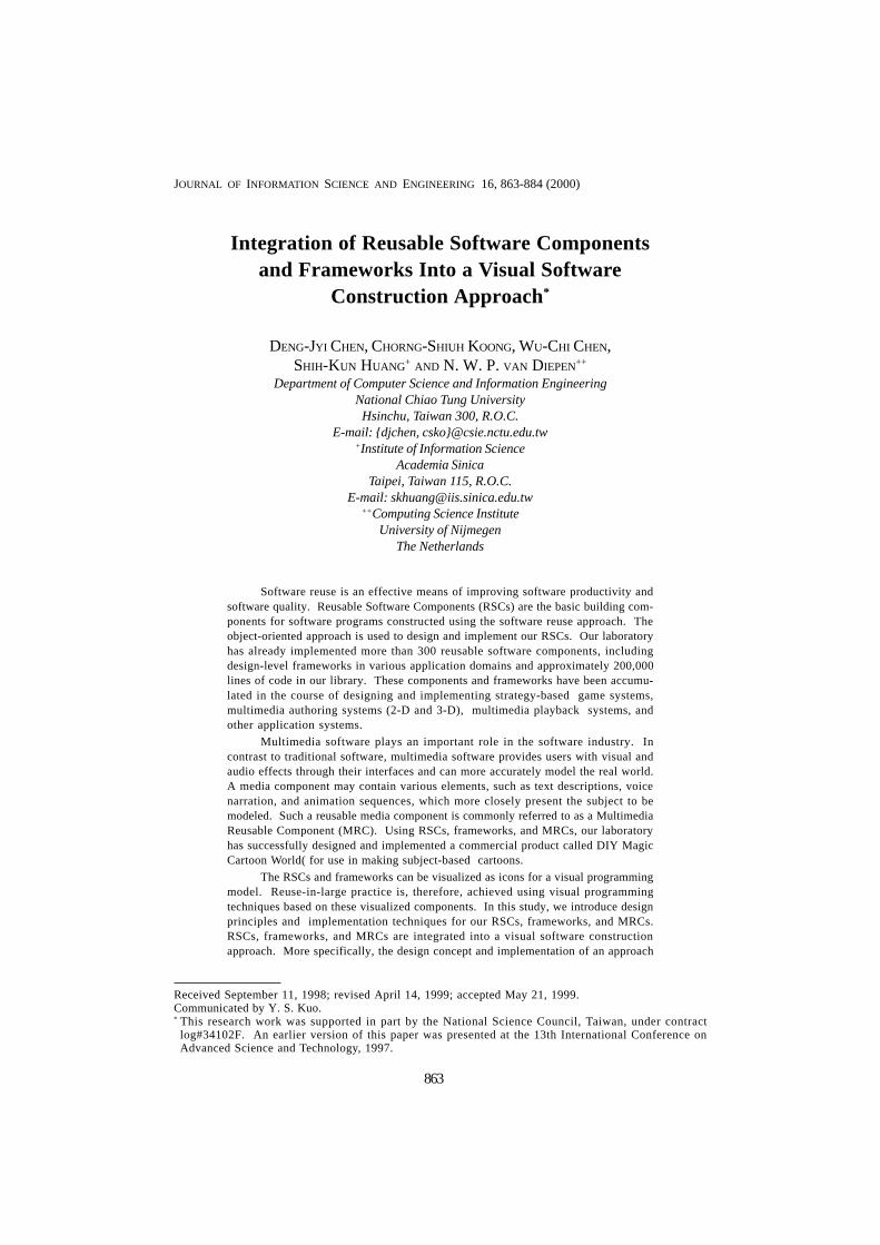
Ideally, a Reusable Software Component or Framework must be designed for use inconstructing many different applications (maximizing applicability) and for easy reuse oradaptation by software designers and programmers(i.e. ease of tailoring for specificapplications). Fig. 1 depicts an ideal RSC or framework in which a 2-dimensional graphic isused.
D. J. CHEN, C. S. KOONG, W. C. CHEN, S. K. HUANG AND N. W. P. VAN DIEPEN866
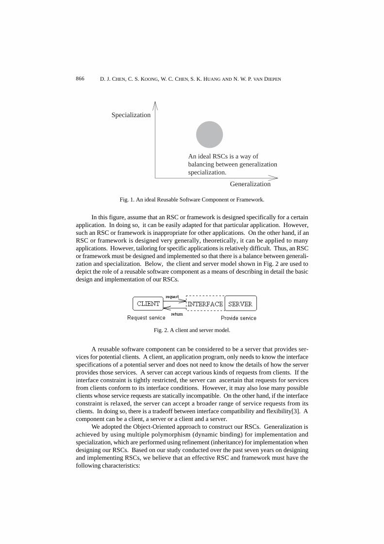
In this figure, assume that an RSC or framework is designed specifically for a certainapplication. In doing so, it can be easily adapted for that particular application. However,such an RSC or framework is inappropriate for other applications. On the other hand, if anRSC or framework is designed very generally, theoretically, it can be applied to manyapplications. However, tailoring for specific applications is relatively difficult. Thus, an RSCor framework must be designed and implemented so that there is a balance between generali-zation and specialization. Below, the client and server model shown in Fig. 2 are used todepict the role of a reusable software component as a means of describing in detail the basicdesign and implementation of our RSCs.
Fig. 1. An ideal Reusable Software Component or Framework.
Fig. 2. A client and server model.
A reusable software component can be considered to be a server that provides ser-vices for potential clients. A client, an application program, only needs to know the interfacespecifications of a potential server and does not need to know the details of how the serverprovides those services. A server can accept various kinds of requests from clients. If theinterface constraint is tightly restricted, the server can ascertain that requests for servicesfrom clients conform to its interface conditions. However, it may also lose many possibleclients whose service requests are statically incompatible. On the other hand, if the interfaceconstraint is relaxed, the server can accept a broader range of service requests from itsclients. In doing so, there is a tradeoff between interface compatibility and flexibility[3]. Acomponent can be a client, a server or a client and a server.
We adopted the Object-Oriented approach to construct our RSCs. Generalization isachieved by using multiple polymorphism (dynamic binding) for implementation andspecialization, which are performed using refinement (inheritance) for implementation whendesigning our RSCs. Based on our study conducted over the past seven years on designingand implementing RSCs, we believe that an effective RSC and framework must have thefollowing characteristics:
An ideal RSCs is a way ofbalancing between generalizationspecialization.
Generalization
Specialization

VISUAL SOFTWARE CONSTRUCTION APPROACH 867
1. Easy to generalize: RSCs and frameworks must be common enough to be used in manyapplications. Restated, an RSC should be designed to accept various types of data usedin different applications.
2. Ease to refine (specialization): RSCs and frameworks must be adaptable, flexible, andextendable enough for use in specialized applications.
3. Clear interface specification: An RSC or framework must provide a set of interfaces for itsclients that gives application users a clear picture of how to use the component.
4. Complete encapsulation: An RSC or framework must protect all its private information.Application users can only use sets of public interface routines to update internal data,thus ensuring that the component will have no side effects when used in clients’applications.
5. Complete testing: RSCs and frameworks must be bug-free. They should be designed andwell tested in such a way as to guarantee quality.
Reusable software components designed according to the above principles will beideal for future reuse. Our laboratory has been attempting to use the Object-Oriented ap-proach according to these principles for the last seven years. In doing so, more than 300reusable components consisting of approximately 200,000 lines of code have beenaccumulated. The sizes of the reusable components range from 500 lines of code to 3,000lines of code, depending on the application.
In addition to good and healthy reusable components, an efficient interconnect lan-guage is also required to integrate these reusable components into useful applicationprograms. Later, in section 4, we will discuss an integration tool and its relative interconnec-tion language.
2.2 Standardization and Classification of RSCs and Frameworks
In general, four kinds of software components can be considered for use in reusablesoftware components or frameworks. Starting from high-level and continuing down the low-level, they are as follows:
1. Requirement specification components: These can be considered as users' requirementanalysis results and analysis-level components (reusable specification analysiscomponents).
2. Design frameworks (or design patterns): These are design-level components (or reusabledesign results) that can be reused to design different application domains. This kind ofcomponent is referred to herein as a Reusable Software Design Framework (RSDF). Theyare designed and implemented using the design principles mentioned above and in [4].
3. Code components: These are software modules or routines referred to herein as ReusableSoftware Components(RSCs). They are designed and implemented using the object-oriented approach and the design principles stated above.
4. Data or media components: These are numerical data, text data, or data in other media.Multimedia software plays an important role in the software industry. Thus, reuse ofmedia data should not be neglected. These components are referred to herein as Multi-media Reusable Components(MRCs).
D. J. CHEN, C. S. KOONG, W. C. CHEN, S. K. HUANG AND N. W. P. VAN DIEPEN868
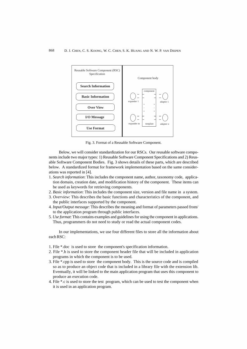
Below, we will consider standardization for our RSCs. Our reusable software compo-nents include two major types: 1) Reusable Software Component Specifications and 2) Reus-able Software Component Bodies. Fig. 3 shows details of these parts, which are describedbelow. A standardized format for framework implementation based on the same consider-ations was reported in [4].1. Search information: This includes the component name, author, taxonomy code, applica-
tion domain, creation date, and modification history of the component. These items canbe used as keywords for retrieving components.
2. Basic information: This includes the component size, version and file name in a system.3. Overview: This describes the basic functions and characteristics of the component, and
the public interfaces supported by the component.4. Input/Output message: This describes the meaning and format of parameters passed from/
to the application program through public interfaces.5. Use format: This contains examples and guidelines for using the component in applications.
Thus, programmers do not need to study or read the actual component codes.
In our implementations, we use four different files to store all the information abouteach RSC:
1. File *.doc is used to store the component's specification information.2. File *.h is used to store the component header file that will be included in application
programs in which the component is to be used.3. File *.cpp is used to store the component body. This is the source code and is compiled
so as to produce an object code that is included in a library file with the extension lib.Eventually, it will be linked to the main application program that uses this component toproduce an execution code.
4. File *.c is used to store the test program, which can be used to test the component whenit is used in an application program.
Fig. 3. Format of a Reusable Software Component.
Reusable Software Component (RSC)Specification
Component body
Search Information
Basic Information
Over View
I/O Message
Use Formatexpander m template adapter n
adapter 1expander 1
component
+ +
+ +
- -
VISUAL SOFTWARE CONSTRUCTION APPROACH 869
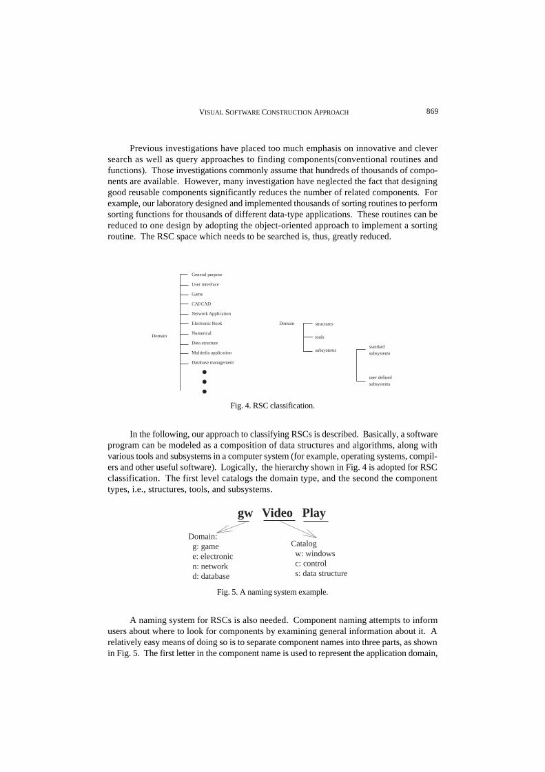
Previous investigations have placed too much emphasis on innovative and cleversearch as well as query approaches to finding components(conventional routines andfunctions). Those investigations commonly assume that hundreds of thousands of compo-nents are available. However, many investigation have neglected the fact that designinggood reusable components significantly reduces the number of related components. Forexample, our laboratory designed and implemented thousands of sorting routines to performsorting functions for thousands of different data-type applications. These routines can bereduced to one design by adopting the object-oriented approach to implement a sortingroutine. The RSC space which needs to be searched is, thus, greatly reduced.
In the following, our approach to classifying RSCs is described. Basically, a softwareprogram can be modeled as a composition of data structures and algorithms, along withvarious tools and subsystems in a computer system (for example, operating systems, compil-ers and other useful software). Logically, the hierarchy shown in Fig. 4 is adopted for RSCclassification. The first level catalogs the domain type, and the second the componenttypes, i.e., structures, tools, and subsystems.
Fig. 5. A naming system example.
gw Video Play
Domain: g: game e: electronic n: network d: database
Catalog w: windows c: control s: data structure
A naming system for RSCs is also needed. Component naming attempts to informusers about where to look for components by examining general information about it. Arelatively easy means of doing so is to separate component names into three parts, as shownin Fig. 5. The first letter in the component name is used to represent the application domain,
Fig. 4. RSC classification.
Domain
General purpose
User interFace
Game
CAI/CAD
Network Application
Electronic Book
Numerical
Data structure
Multiedia application
Database management
Domain structures
tools
subsystemsstandard
subsystems
user defined
subsystems

D. J. CHEN, C. S. KOONG, W. C. CHEN, S. K. HUANG AND N. W. P. VAN DIEPEN870
the second letter is used to represent the component type, and the final part is used torepresent the component function. Fig. 5 shows a Windows game component that can usedfor playing a video.
The above information provides a basis for users to retrieve and use existing compo-nents in their applications. Later, in section 4, we will present a Component Retrieval System,using the proposed classification structure and naming system, and then implement andintegrate it into a visual programming environment.
3. A VISUAL SOFTWARE CONSTRUCTION PARADIGM FORREUSABLE COMPONENTS AND FRAMEWORKS
MRCs are developed in order to represent requirement scenarios[6]. Using visualrepresentations of requirement specifications allows one to view such requirements as ani-mation sequences so that one does not have to read or study voluminous requirementdocuments. Such an innovative software approach provides users with visual aids whichcan help them better understand the software requirements. This approach also providesdesigners with a natural means of communicating with users and, thus, to receive moreaccurate feedback from users regarding the requirements under consideration. In section 2,we presented the design principles and implementation approach for our RSCs and Frame-works in RSCs, Frameworks, MRCs, and the visual programming environment. A novelparadigm for software construction is presented in the following.
Fig. 6. A Visual Software Construction (VSC) model.
ComponentConstructor
SystemAnalyst
Customer
Visual RequirementAuthoring System
(VRAS)
MRCManager
Visual RequirementSpecification
Designframework
Code/Datacomponents
SoftwareProgram
VisualProgrammingEnvironment
3.1 A Visual Software Construction Model
Semantic pictures, commonly referred to as icons, can be used to represent RSCs,frameworks, and MRCs in a visual programming environment [17]. Restated, an icon iscreated for each RSC, MRC, and Framework. Consequently, a bank of icons are catalogedand named as described in section 2.2. To effectively use these icons, a software construc-tion paradigm must be developed. Consider the Visual Software Construction (VSC) Modeldepicted in Fig. 6.
The software construction process can be divided into two major phases, requirementconstruction and program construction. MRCs are the bases for requirement constructionwhile RSCs and Frameworks are the bases for program construction.
During the requirement construction phase, a Visual Requirement Authoring System(VRAS) is employed to produce a visual requirement specification using MRCs. Such avisual requirement specification is achieved by system analysts and passed onto users

VISUAL SOFTWARE CONSTRUCTION APPROACH 871
(customers) for evaluation. Modifications are made when analysts and users disagree.During modification, analysts again invoke the VRAS to instruct the MRC Manager Systemto retrieve an appropriate MRC for modification. If the MRC Manager System does notlocate such an MRC, then such an MRC is fabricated by invoking the MRC ComponentConstructor. The constructed MRC is then stored in the MRCs Manager System by theanalyst using the Visual Requirement Authoring System. During fabrication of an MRC,tools for aggregating video, motion pictures, static image picture, voice, and text together toproduce a visual presentation are supported for most common multimedia computer systems.The VRAS also provides a rich set of functions to help MRC designers fabricate desiredMRCs. This innovative requirement representation paradigm provides analysts and design-ers with a natural means of communicating with users (customers) and receiving more accu-rate responses from users concerning the requirement under consideration.
During the program construction phase, the Visual Programming Environment (VPE)is employed to produce programs according to the requirements obtained during the require-ment construction phase. Ideally, the requirement representation film from the MRC isautomatically verifed to produce a list of design patterns (frameworks) that are closely appli-cable to the requirement under consideration. Also, a list of RSCs applicable to the designpattern (framework) is produced automatically. However, at the present time, the kinds ofdesign patterns (or frameworks) and RSCs that are needed must be manually identified toconstruct programs for the requirements under consideration. Once a list of these frame-works and RSCs has been identified, the VPE provides tools which designers can use toproduce the corresponding programs. Thus, the Visual Programming Environment mustprovide the following: 1) a visual paradigm for producing visual programs, based on the useof icons to represent various frameworks and RSCs, and a code generator for translating thevisual program into target code (high-level programs), and 2) a hyper-text editor that allowsprogrammers to edit programs when they reuse the design frameworks and RSCs. An inter-connection language is defined for connecting icons so as to produce an iconic program. ACode Generator takes these iconic programs and translates them into programming languagesource code.
3.2 Advantages of the Proposed Construction Model
Many investigations have cited traditional software construction models as causingproblems in requirement specification, design, coding, testing, and maintenance. A detailedlist of problems can be found in [19]. Some of these problems can be alleviated using theproposed construction model. The benefits of the proposed construction approach are asfollows.
1. A Visual Requirement Authoring System, instead of the traditional (NOTE: “conven-tional” instead ?) requirement-gathering process, provide users with visual images thatallow them to better understand the software requirements. It also provides analysts anddesigners with a natural means of communicating with users and receiving more accuratefeedback from users concerning the requirements under consideration.
2. The proposed approach provides a prototyping capability, as evidenced by its reuse ofdesign frameworks and RSCs during the construction of application software. A proto-type satisfying the software requirements under consideration can be built using theicons representing frameworks and RSCs. Thus, users (and customers) can observewhether or not the functionality satisfies their requirement at an early stage before thefinal system is implemented.

D. J. CHEN, C. S. KOONG, W. C. CHEN, S. K. HUANG AND N. W. P. VAN DIEPEN872
3. The proposed approach encourages good software programming practices. Encouragingdesigners and programmers to reuse the design frameworks and components leads toaccumulation of their own design frameworks and RSCs. Accumulation of reusable com-ponents and frameworks is essential for improving software productivity and quality.
4. Frameworks and RSCs are thoroughly implemented and tested before reuse. Doing soencourages the design and implementation of healthy (bug-free and side-effect-free)components. Consequently, the application software based on these healthy compo-nents or frameworks needs less time for debugging. Thus, the testing cost can bereduced.
5. In a visual programming paradigm, a top-level iconic program represents the system struc-ture while a lower-level one represents the software program. When a modification orchange in the iconic program is required, designers or programmers can easily locate theicon requiring replacement or modification. By substituting the icon or reconnectingicons, the code generator can immediately generate a new version of the software program.
6. The proposed construction model encourages reuse-in-large practice, thereby improvingsoftware productivity and quality.
Other merits of using a visual programming technique, such as 2-D graphicprogramming, are as follows: it is able to easily learn and understand; graphic programs caneasily present higher-level abstractions; graphic programs are easily modified with fewerrors; icon replacement is easier than text modification. Further details can be found in [12,13, 15].
4. IMPLEMENTATION ISSUES CONCERNING THEPROPOSED CONSTRUCTION APPROACH
In section 3, we briefly described the visualized software construction model. In thefollowing, we will present implementation issues concerning the proposed constructionapproach. These issues can generally be divided into two main groups: 1) requirement-construction phase issues and 2) program-construction phase issues.
4.1 Implementation Issues in the Requirement-Construction Phase
The requirement-construction phase focuses mainly on implementing a Visual Re-quirement Authoring System that allows users to select the various MRCs stored in theMRCs Manager System and turn them into films (visual presentations) that can be played forusers (customers). Fig. 7 depicts the model.
RequirementAuthoring
MRCBuildTool
MRCManagement
System
MRCDatabase
GetRetrieve
MRCRequest
Load
Load
Output
Input
RequirementPresentaionScript file Input
RequirementPresentation
Playback
Fig. 7. A Visual Requirement Authoring System.

VISUAL SOFTWARE CONSTRUCTION APPROACH 873
The MRCs must be designed in a standardized format, and MRC designers usuallyseek the assistance of artists in drawing meaningful and simple motion pictures to describethe basic meanings of events(requirements scenarios). The authoring system must providevarious functions that allow analysts to change MRC attributes, to make animation se-quences for events in MRCs, and to assemble several MRCs to satisfy scenario-basedrequirements. These scenario-based requirements are then combined into featurepresentations(films) and played for user evaluation. We have discussed this subject indetail in [6]. Below, we will highlight some functions supported by our commercial product,DIY Magic Cartoon World [14], which is similar to the Visual Requirement Authoring Systemdiscussed herein.
In the authoring system, visual requirement specification is analogous to a cartoonfilm. Cartoon films contain sets of scenes, which are similar to sets of MRCs. The scenes arethe base of a cartoon film. Correspondingly, MRCs is the base of a visual requirement. Ascene can have several actors whose characteristics can be defined using a set of functionsprovided by the authoring tool, depending on the user’s needs. For example, an actor’sscenario can be described using the authoring tool. Several acting scenarios can be definedso as to make a scene. Similarly, an MRC may contain several requirement scenarios basedon the user’s needs. Thus, an MRC can be created and edited by an analyst based on thefunctions provided by the authoring system. Functions supported in the current authoringsystem include the following:
1. selecting and moving actors (representing requirement scenarios) from an actor bank(representing requirement scenario databases) to a designated place in a scene (representingMRCs);
2. recording voice narrative sessions for actors (requirement scenarios) and scenes (MRCs);3. enlarging and scaling-down selected actors (representing particular requirement scenarios);4. allowing left and right sequence changes between two actors (representing requirement
scenarios);5. allowing up and down sequence changes between two actors (representing requirement
scenarios);6. making animations of scenarios at different presentation speeds;7. allowing foreground and background changes among actors (representing requirement
scenarios);8. making sequential presentations of several selected actors (representing requirement
scenarios);9. making several selected actors perform in parallel;10. defining beginnings, progressions, and endings for scenes;11. providing other features such as setting special effects and background music for scenes,
previewing scenes just completed, discarding unwanted actors, and so on.
Notably, the above features are all presented in visual form. Thus, users are performingvisual programming when they are using these functions to make cartoon films (or visualrequirement representations). The details of how to use MRCs to produce a visual require-ment can be found in [6].
4.2 Implementation Issues in the Program-Construction Phase
Program construction concentrates mainly on implementing a Visual ProgrammingEnvironment. The Visual Programming Environment takes visual requirements and trans-forms them into target software programs. Fig. 8 presents an outline of the system structure.

D. J. CHEN, C. S. KOONG, W. C. CHEN, S. K. HUANG AND N. W. P. VAN DIEPEN874
According to Fig. 8, several non-trivial tasks must be performed to implement a visualprogramming environment.
Fig. 8. Visual programming system structure.
ComponentData Base
Component retrievesystem, DBMS
QueryIcon Manager
candidate frameworksand
RSCs
Use selectedIcons (Objects)
Visual programning
draft
Icon Program
source codegenerator
C++ Source Code
Text Editorand
Text Viewer
OueryViewAddUpdate
1. Each Framework or RSC stored in the Components Database must be visualized at the timeit is selected as a candidate for program construction and then placed into an icon pool bythe Icon Manager.
2. A visual programming model must be defined in order to make an iconic program.3. An icon interconnection language and its corresponding code generator must be
implemented.
4.2.1 Visualizing the frameworks and RSCs
In contrast to hardware ICs, which have fixed semantic meanings (true, false, or don'tcare) for their pins when they are connected to other ICs, software programs depend onmessage names, and on parameter types and numbers during message-binding with othersoftware programs. Visualization of software components (frameworks and RSCs) by defin-ing graphic bitmaps (icons) of their input and output layouts is used in our system. Fig. 9presents a component layout.
Fig. 9. Component layout.
Creating a visualized component involves re-packaging a component from its originaltext description. Re-packaging a component consists of the following three steps:

VISUAL SOFTWARE CONSTRUCTION APPROACH 875
Step 1: Find or draw a meaningful picture or icon to represent the component.Step 2: Modify the original component by adding a virtual member function, called a connect
(), to the component. The connect() member function is implemented by means ofdynamic binding that links with other components. Thus, a component can bedynamically bound to another components needing service from this component.
Step 3: Define component input pins and output pins according to the member functionsdefined in the component.
For example, the nth output pin of component A is connected to the input pin ofcomponent B, as shown in Fig. 10. According to this figure, execution of component Binvokes function n in component A. Using C++ notation, it will be implemented as B.connect(&A, n). If the component is a design framework, we add an execution() function toit to initiate the execution sequence. An invocation of this function initiates the execution ofall the connected components.
Fig. 10. Component interconnection.
4.2.2 A visual programming model
Many visual programming models have been proposed [12, 13, 15]. A visual program-ming model can be as complex as a general-purpose programming language, with support forcomplicated programming structures. This visual programming model provides users aconvenient way to produce powerful and complicated visual programs (or iconic programs)for modeling low-level applications. Meanwhile, another type of visual programming modelprovides only a limited set of programming structures, thus enabling users to produce simplebut reasonable visual programs (or iconic programs) for special domains. The visual pro-gramming model proposed herein is of the latter type. Our choice was made on the basis ofprogramming-in-large and reuse-in-large practices. Writing a simple subroutine, such assorting or finding a square root, using visual or icon programming would be unnecessaryexcept for very special purposes. Instead, these simple routines should be implementedusing a high-level language and encapsulated as icons for use in higher-level applications.In this manner, the power of a visual program can be enhanced. In the following, we intro-duce a relatively simple visual programming model for program construction based on theuse of our RSCs and frameworks.
We use a computer processing model which contains three parts: an input unit, pro-cessing unit, and output unit, as shown in Fig. 11, to present the visual programming model.
INPUT PROCESSING OUTPUT
output deviceoutput-UI
input deviceinput-UI
Basic control structure - sequential - branch - loop
Design franeworkCode/Data components
Fig. 11. The visual programming model.

D. J. CHEN, C. S. KOONG, W. C. CHEN, S. K. HUANG AND N. W. P. VAN DIEPEN876
The input unit handles all input devices and input-end user interfacing while theoutput unit takes care of all output devices and output-end user interfacing. The processingunit performs all operational flows according to application requirements. In the proposedmodel, each device (user interface) in the input, output, and processing units is treated as acomponent or as a combination of components. Simple control structures, includingsequential, branching, and looping, structures, are provided in the processing unit to de-scribe the control flow. Icon types, such as frameworks and RSCs, are also introduced forprogramming-in-large (or reuse-in-large) through interconnections among icons.
4.2.3 Control structure
The programming control structures are also represented as visualized icons. Twolevels of control structure are defined, the basic control structure and the system-levelcontrol structure. Fig. 12 (a) shows that the basic control structure includes an if-then-elsestructure, a do-loop structure, a case-switch structure and sequential flows in the compo-nent layout. The system-level control structure is the design framework component shownin Fig. 12(b).
Fig. 12. Control structure.
If condition
Then part
Else part
If.. Then.. Else
Do condition
Loop part
Do.. Loop
invoke
Sequential flow
Job 1
Job 2
Job 3
Case condition
Case.. Switch
Switch
Control InputConditions
else
IF
then
Design level compnent
Control Outout 1(invoke subsystem 1)
Control Outout 2(invoke subsystem 2)
Control Outout 3(invoke subsystem 3)
4.2.4 Data types
Primitive data types, such as integers, characters, and floating points, provided inconventional procedural programming languages are not recommended for programming-in-large or reuse-in-large practices. As mentioned earlier, these data types introduce a greatdeal of interconnection complexity and should only be used as icons for constructing reus-able components or frameworks. Thus, our system uses extension data types and user-defined data types as well as primitive data types. Extension data types contain not onlydata, but also operations on the data. The RSCs discussed earlier are of this data type. User-defined data contains more information than do RSCs, and interconnection information(control flow) for several RSCs is provided; frameworks are examples of this kind of data.
Type conversion can be done implicitly or explicitly. Primitive data types are handledby the compiler. All extension data type conversions are handled by the component objectitself. User-defined type objects may also need to perform type conversions. In the pro-posed system, all conversion functions are defined and implemented using polymorphismmechanisms. During parsing of component interconnections, the conversion functions areinvoked automatically.
(a) (b)

VISUAL SOFTWARE CONSTRUCTION APPROACH 877
4.2.5 A visual program example
An icon program consists of icons, links, and labels.Icons are the bases of visual programs. The top-level icons represent the system
structure, relationships among subsystems. An icon can be any kind of RSC. The details ofa subsystem can be viewed by clicking on the icon representing the subsystems. In addition,the body of an RSC can be viewed by clicking on the icon representing that component.Connections between icons alone can define the semantic meanings of visual programs.
Links are used to interconnect components so that they to form visual programs.Links represent message-passing and control transfers between components. Messageresolution is achieved by individual components. When designing RSC interfaces, all pos-sible message-passing must be considered. Links can only be used to connect input andoutput pins. The code generator detects illegal connection patterns, such as attempts toconnect two inputs.
Labels are used only for documentation purposes and can appear anywhere in iconprograms. The code generator skips all labels during source code-generation.
Fig. 13 shows a simple example of an icon program. This example program acceptsinputs from a keyboard, converts input characters from upper-case to lower-case, encodesthe input characters and finally outputs them to the screen.
4.3 A Visual Programming Environment (VPE)
In this section, we will present the environment used to produce the visual programshown in Fig. 13.
The environment starts with a Component Retrieval System that allows users to locatepotential RSCs and frameworks for use in their applications. Similar to most database systems,it provides functions like querying, inserting, updating, and deleting for RSC management.Fig. 14 shows the user interface.
(a) Functions of the retrieval system (b) RSC querying, insertion, updating, and deletingFig. 14. Component retrieval system user interface.
Fig. 13. An example of an iconic program.
UpToLow
Encode
inputFromKeyboard
ProcessReceptacle
OutputToScreen
File
prochar
prochar
prochar
inchar
outchar
input
process
output
plug1plug2plug3plug4plug5

D. J. CHEN, C. S. KOONG, W. C. CHEN, S. K. HUANG AND N. W. P. VAN DIEPEN878
Fig. 14(a) shows the functions provided by the component retrieval system while Fig.14(b) demonstrates how the system can be asked to locate a general-purpose RSC stack.When the keyword for a desired component is input, the system responds with a list ofpotential candidates. Fig. 15(a) shows matched the RSC STACK-ARRAY with its generalinformation given in the introduction field. Users can also more closely examine the matchedRSC by clicking on the view button on the right-hand side of the window. This opens a newwindow that displays relevant information about the RSC, as shown in Fig. 15(b). This RSCinformation, as described in Fig. 3, is stored in a *.doc file and is now seen in this window.Furthermore, by clicking on the view *.H button, one can view the component header. Thetest program can be viewed by clicking on view *.CPP.
(a) A matched RSC (b) Detailed information about an RSCFig. 15. A matched RSC with its relevant information.
Once the matched component has been examined and evaluated for applicationsuitability, the OK button is clicked to determine whether the match is appropriate; in addition,an icon representing this matched RSC is created and added to the Icon Manager. If amatched RSC requires modification, then the Text Editor is invoked to perform this task.
Eventually, a set of icons representing the matched RSCs for visual program construc-tion will be present in the Icon Manager. These icons are displayed in the Visual IconManger area shown in Fig. 16. The Visual Programming Draft is a hyper-text editor forcreating visual programs (or iconic programs). Programmers can drag icons from the IconManager to the draft area and drag links to connect icons according to their interfaceconnections. Icons dragged into the draft area represent instances of matchedRSCs, and labels can be used to make these icons more understandable.
Fig. 16. The Icon Manager and the visual programming draft area.

VISUAL SOFTWARE CONSTRUCTION APPROACH 879
The icon program shown in Fig. 13 was constructed using the VPE shown in Fig. 17.The internal form (script file) representing the icon program is then read and parsed by
the Code Generator to produce the corresponding source code. Table 1 lists the source codefor the icon program shown in Figs. 13 and 17.
If a programmer wants to change the input device from a keyboard to a file forthe program shown in Fig. 17 and the output device from a screen to a file, all he orshe has to do is replace the input and output icons with other input and output icons.Fig. 18 shows such a replacement.
Fig. 17. An icon program example.
(a) (b)
Fig. 18. An example of icon replacement.
Reuse of the rest of the program structure can be accomplished through this kind ofsimple replacement in a VPE system. Thus, an entire visual program can be treated as aframework.
4.4 Visual Programs and Frameworks
Application frameworks are very important for the software industry and academiasince software systems are becoming increasingly complex. Designing frameworks is al-ready a challenging task. Lack of an appropriate method for accumulating frameworks andreusing them discourages software constructors from using them in their programming

D. J. CHEN, C. S. KOONG, W. C. CHEN, S. K. HUANG AND N. W. P. VAN DIEPEN880
work. The visual programming approach provides a natural method for framework accumu-lation and reuse. The visual program depicted in Fig. 13 can be viewed as a frameworkbecause it also gives the designer a relatively easy means of replacing or modifying icons toproduce another application program. The visual program depicted in Fig. 17 also providesanother example, indicating the frameworks’ ease of modification. Accumulating visualprograms simply involves creating other meaningful icons to represent the visual programsand storing them in the Component Retrieval System for future reuse. Thus, a visual pro-gramming approach makes reuse and accumulation of frameworks easy.
5. CONCLUSIONS
Software reuse is an effective means of increasing software productivity and quality.Many reusable components have already been designed and used in various applications.Framework design is also promising as a major programming paradigm for the next century.However, reusable components and frameworks are still difficult to reuse unless they areintegrated into an innovative software construction approach.
Table 1. Sample source code.
#include “C:\SOFTIC\ICDATA\file.h”#include “C:\SOFTIC\ICDATA\infromke.h”#include “C:\SOFTIC\ICDATA\outtoscr.h”#include “C:\SOFTIC\ICDATA\ProRecep.h”#include “C:\SOFTIC\ICDATA\uptolow.h”#include “C:\SOFTIC\ICDATA\encode.h”#include <windows.h>#pragma argsusedint PASCAL WinMain(HANDLE hInstance,
HHANDLE hPrevInstance,LPSTR IpszCmdLine,int cmdShow)
{_InitEasyWin();file file_0;InputFromKeyboard InputFromKeyboard_1;OutputToScreen OutputToScreen_2;Process Receptacle ProcessReceptacle_3;UpToLow UpToLow_4;Encode Encode_5;file_0.connect (& InputFromKeyboard_1,0);file_0.connect(&Process Receptacle_3,1);Process Receptace_3.connect(&Up ToLow_4,0);Process Receptacle_3.connect (&Encode_5,1);file_0.connect(& Output To Screen_2,2);return file_0.execution();}

VISUAL SOFTWARE CONSTRUCTION APPROACH 881
This study has presented a novel approach to developing a visual software construc-tion system for reusing software components and frameworks. The proposed approachaddresses three important issues:
1. Reusable components and frameworks must be integrated into a software constructionprocess. Integration using visual programming is a natural choice since the visual pro-gramming model offers the optimum means of describing programming-in-large and reuse-in-large practice. Reusable components and frameworks can be encapsulated and visual-ized as icons for higher-level programming using visual programming, thus making thereuse of existing reusable components and frameworks in future application. Thus, reuse-in-large can be achieved.
2. Reusable components and frameworks must be accumulated in a standardized format. Inaddition, an appropriate classification structure and a naming system must be employedto manage them. More specifically, a component-management system for these reusablecomponents and frameworks must be integrated into a visual programming model toprovide a visual programming environment for software constructors. When this envi-ronment is used, a visual program can be treated as a new framework and can be accumu-lated into the environment for future reuse.
3. Requirement specification can be visualized. Multimedia Reusable Components makevisual requirement presentation possible. The use of visual requirement specificationallows one to view requirements as animation sequences so that it is not necessary to reador study voluminous requirement documents. This innovative software requirement rep-resentation paradigm provides designers with a natural means of communicating withusers and, thus, receiving more accurate feedback from them concerning the require-ments under consideration.
The visual software construction paradigm provides a new direction for academicresearchers and for software developers who wish to obtain better solutions for softwareconstruction.
REFERENCES
1. Grady Booch, Object-Oriented Design with Applications, Benjamin/Commings Pub-lishing Company, Inc., Redwood City, 1991.
2. Grady Booch, Software Components with Ada, Benjamin/Cummings Publishing Company,Inc., Redwood City, 1987.
3. D. J. Chen and S. K. Huang, “Interface of reusable software components,” The Journalof Object-Oriented Programming, Vol. 5, No. 8, 1993, pp. 42-53.
4. D. J. Chen and D. T. K. Chen, “An experimental study of using reusable software designframeworks to achieve software reuse,” The Journal of Object-Oriented Programming,Vol. 7, No. 2, 1994, pp. 56-68.
5. D. J. Chen and P. J. Lee, “On the study of software reuse using reusable C++ components,” TheJournal of System and Software, Vol. 20, No. 1, 1993, pp. 19-36.
6. W. C. Chen, “A reuse-based software construction paradigm for visualized reusablecomponents and frameworks,” a Ph.D. dissertation, Computer Science and InformationEngineering, National Chiao-Tung University, Taiwan, 1998.

D. J. CHEN, C. S. KOONG, W. C. CHEN, S. K. HUANG AND N. W. P. VAN DIEPEN882
7. B. Cox, Object-Oriented Programming: An Evolutionary Approach, Addison-Wesley,Reading, Mass, 1986.
8. P. Coad and E. Yourdon, Object-oriented Analysis, Prentice-Hall, New York, 1990.9. M. E. Fayad, W. T. Tsai, and Fulghum, “Transition to object-oriented software
development,” Communication of the ACM, Vol. 39, No. 2, 1996.10. P. Freeman, “A perspective on reusability,” The Computer Society of the IEEE, 1987, pp.
2-8.11. E. Gamma, R. Helm, R. Johnson, and J. Vlissides, Design Patterns: Elements of Reusable
Object-Oriented Software, Addison-Wesley, Reading, Mass, 1995.12. M. Hirakawa, “HI-VISUAL iconic programming,” in Proceedings of IEEE Workshop on
Visual Language, 1987, pp. 305-314.13. M. Hirakawa, “An iconic programming system, HI_VISUAL,” IEEE Transactions on
Software Engineering, Vol. 16, No. 10, pp. 1178-1184.14. G. Y. Hsu and C. S. Koong, “A visual authoring tool for cartoon movie,” Technical
Report of the Best Wise International Computing Co., Taiwan, 1996.15. T. D. Kimura, A. Apte, S. Sengupta, and J. W. Chen, “Form/formula-a visual program-
ming paradigm for user-definable user interfaces,” IEEE Computer, Vol. 28, No. 3, 1995,pp. 27-35.
16. M. Lenz, H. A. Schmid, and P. F. Wolf, “Software Reuse through Building Blocks,” IEEESoftware, Vol. 4, No. 4, 1987, pp. 34-42.
17. C. L. Li, “An object-based icon programming methodology,” Master thesis, ComputerScience and Information Engineering, National Chiao-Tung University, Taiwan,1992.
18. M. D. Mcllroy, “Mass-produced software components,” in Software Engineering Con-cepts and Techniques, NATO Conference on Software Engineering, 1969.
19. R. S. Pressman, Software Engineering-A practitioner’s Approach, McGraw-Hill company,Inc., New York, 1997.
20. R. Prieto-Diza and P. Freeman, “Classifying software for reusability,” IEEE Software,Vol. 1, No. 1, 1987, pp. 6-16.
21. J. Rumbaugh, M. Blaha, W. Premerlani, F. Eddy, and W. Lorensen, Object-OrientedModeling and Design, Prentice-Hall, New York, 1991.
22. D. Rogerson, Inside COM, Microsoft Press, 1996.23. http://www.javasoft.com/beans/index.html24. G. Booch, “Designing an application framework,” Dr. Dobb’s Journal, Vol. 19,
No. 2, 1994, pp. 24-31.25. R. E. Johnson, “How frameworks compare to other object-oriented reuse
techniques: Frameworks = Components + Patterns,” Communications of the ACM,Vol. 40, No. 10, 1997, pp. 39-42.
26. M. E. Fayad and D. C. Schmidt, “Object-oriented application frameworks,” Com-munications of the ACM, Vol. 40, No. 10, 1997, pp. 32-38.
27. Demeyer, Meijler, Nierstrasz, and Steyaert, “Design guidelines for tailorableframeworks,” Communications of the ACM, Vol. 40, No. 10, 1997, pp. 60-64.
28. Baumer, Gryczan, Knoll, Lilienthal, Riehle, and ZZZullighoven, “Framework de-velopment for large systems,” Communications of the ACM, Vol. 40, No. 10,1997, pp. 52-59.
29. Brugali, Menga, and Aarsten, “The framework life span,” Commnuications of the ACM,Vol. 40, No. 10, 1997, pp. 65-68.

VISUAL SOFTWARE CONSTRUCTION APPROACH 883
Deng-Jyi Chen ( ) received the B.S. degree in Com-puter Science from Missouri State University (Cape Girardeau), andthe M.S. and Ph.D. degrees in Computer Science from the Univer-sity of Texas (Arlington) in 1983, 1985, and 1988, respectively. He isnow a professor at National Chiao-Tung University (Hsin Chu,Taiwan). He has published nearly 100 referreed journal and confer-ence papers in the areas of reliability and performance modeling ofdistributed systems, computer networks, object-oriented systems,and software reuse. Professor Chen works very closely with theindustrial sector and provides consulting services for many localcompanies (both software and hardware companies). He has beena leader in designing and implementing several commercial products,
some of which have been marketed around the world. Dr. Chen also has received researchgrants yearly from the National Science Council Taiwan for the last several years and nowserves as a committee member in several academic and industrial organizations.
Chorng-Shiuh Koong ( ) received his B.S. de-grees in education from National Taiwan Normal University,Taiwan, in 1989 and the M.S. degree in computer scienceand information engineering from National Chiao-TungUniversity, Taiwan, in 1995. Currently, he is a Ph.D. candidateat National Chiao-Tung University, Taiwan. His research interestsinclude object-oriented technology, component technology, andvisual programming.
Wu-Chi Chen ( ) received his B.S. and Ph.D. de-grees in Computer Science and Information Engineering fromNational Chiao Tung University(Hsinchu, Taiwan) in 1992 and1998. Since then, he has joined the Taiwan SemiconductorManufacturing Co. as an Principal CIM Engineer. His researchinterests include software engineering and object-oriented modeling.
Shih-Kun Huang ( ) received his B.S., M.S. and Ph.D.degrees in Computer Science and Information Engineering from Na-tional Chiao-Tung University, Hsinchu, Taiwan, in 1989, 1991 and1996, respectively. Since then, he has joined the Institute of Infor-mation Science as an assistant research fellow. His research areasinclude object-oriented technology and software security.

D. J. CHEN, C. S. KOONG, W. C. CHEN, S. K. HUANG AND N. W. P. VAN DIEPEN884
N.W.P. (Niek) van Diepen received his M.Sc. from the Uni-versity of Utrecht in 1985. He then spent 3 years at the Center forMathematics and Computer Science in Amsterdam, working onthe ESPRIT project GIPE (Generating Interactive ProgrammingEnvironments). In 1988, he joined the University of Nijmegen inThe NWO(Netherlands Foundation for Scientific Research) projectSTOP(Specification and Transformation Of Programs). He receivedhis Ph.D. degree there in 1994. He is employed as an AssistantProfessor at the University of Nijmegen, currently assisting at thePolytechnical University of Arnhem-Nijmegen. His current researchinterests are in Object-Orientation, especially modularization and
software library construction, and in transformational programming.