integration studies of post-combustion co 2 capture by wet ... filehamburg university of technology...
TRANSCRIPT

Integration Studies of
Post-Combustion CO2 Capture by
Wet Chemical Absorption into
Hamburg University of Technology
Institute of Energy Systems
Wet Chemical Absorption into
Coal-fired Power Plant
4th International Conference on Clean Coal Technologies
17 – 21 May 2009. Dresden. Germany
Imo Pfaff
Jochen Oexmann
Alfons Kather
Institute of
Energy Systems
Session: Carbon Capture Technolgies (II)

Hamburg University of Technology
Institut of Energy Systems
Post-combustion CO2 capture by wet chemical absorption processes
+ Based on the conventional steam power plant process
+ Retrofittable
− Relatively high efficiency penalty
Efficiency losses due to
▸ CO2 capture unit
• Heat demand to regenerate solvent
Background
Other CO2
compression
Power
Structure of efficiency losses
• Heat demand to regenerate solvent
• Power demand
▸ CO2 compression
▸ Further auxiliary loads (fans etc.)
Focus of most studies retrofit integration
�This study: focus on Greenfield
▸Overall power plant optimization possible
2
CO2 capture unit
Heat
Hamburg University of Technology
Institut of Energy Systems
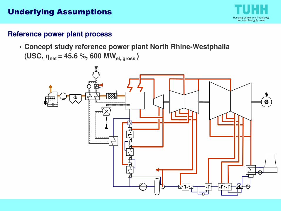
Reference power plant process
▸ Concept study reference power plant North Rhine-Westphalia
(USC, ηnet = 45.6 %, 600 MWel, gross )
Underlying Assumptions

Hamburg University of Technology
Institut of Energy Systems
Reference power plant process
▸ Concept study reference power plant North Rhine-Westphalia
(USC, ηnet = 45.6 %, 600 MWel, gross )
Wet chemical absorption process
▸MEA based process with optimistic performance parameters:
- 3.3 GJ/t CO2 @ 90% capture rate
���� Steam supply pressure 3.3 bar
to atmosphere
Underlying Assumptions
���� Steam supply pressure 3.3 bar
flue gasfrom FGD
steam
reboiler
to compression

Hamburg University of Technology
Institut of Energy Systems
Reference power plant process
▸ Concept study reference power plant North Rhine-Westphalia
(USC, ηnet = 45.6 %, 600 MWel, gross )
Wet chemical absorption process
▸MEA based process with optimistic performance parameters:
- 3.3 GJ/t CO2 @ 90% capture rate
���� Steam supply pressure 3.3 bar
Underlying Assumptions
���� Steam supply pressure 3.3 bar
CO2 compression process
▸ 8-staged compressor, each stage intercooled
▸ Pipeline conditions 110 bar, 40 °C
1 2 3/4 6/75 8

Hamburg University of Technology
Institut of Energy Systems
Study Approach
CCS power plant
▸ Design at full load with 90 % CO2 capture rate
▸ Flow sheet layout unchanged to maintain comparability
▸MEA process parameters not varied
For each design case
▸Optimization of steam bleed pressures of pre-heat train
▸Optimal reboiler condensate return point
Conducted analyses
1. Evaluate impact of integration
2. Optimization by waste heat recovery measures
6

Hamburg University of Technology
Institut of Energy Systems
General Integration Issues
Interface requirements delivered by the power plant
1. Heat for regeneration in sufficient quantity and quality
2. Power to drive the CO2 compressor, pumps and fans
3. Cooling water to discharge waste heat
Only reasonable option extract LP-steam form IP/LP crossover pipe
▸ Best suited to extract large mass flows (~ 50% needed)
▸ To meet the required quality (T,p) over entire load range
• steam attemperation
7
reboiler
To condensate
pre-heat train
From IP/LP
crossover pipe
spray
attemperator

Hamburg University of Technology
Institut of Energy Systems
Interface requirements delivered by the power plant
1. Heat for regeneration in sufficient quantity and quality
2. Power to drive the CO2 compressor, pumps and fans
3. Cooling water to discharge waste heat
Only reasonable option extract LP-steam form IP/LP crossover pipe
▸ Best suited to extract large mass flows (~ 50% needed)
General Integration Issues
3.3 bar to CCU
IP/ LPcrossover pipe
▸ To meet the required quality (T,p) over entire load range
• steam attemperation
• pressure maintenance concept
8

Hamburg University of Technology
Institut of Energy Systems
Impact of Pressure of the IP/LP Crossover Pipe
50
60
70
80
90
100
35.4
35.5
35.6
35.7
35.8
35.9
Ne
t e
ffic
ien
cy a
t d
esi
gn
po
int
in %
Min
ima
l lo
ad
wit
ho
ut
thro
tte
lin
g in
IP/L
P c
ross
ov
er
pip
e i
n %
9
0
10
20
30
40
34.9
35.0
35.1
35.2
35.3
3.3 3.5 3.7 3.9 4.1 4.3 4.5 4.7 4.9 5.1 5.3 5.5
IP/LP crossover pipe design pressure in bar
base case- 10.6 % N
et
eff
icie
ncy
at
de
sig
n p
oin
t in
%
Min
ima
l lo
ad
wit
ho
ut
thro
tte
lin
g in
IP/L
P c
ross
ov
er
pip
e i
n %

Hamburg University of Technology
Institut of Energy Systems
Optimisation by Waste Heat Recovery (I)
Potential sources of waste heat for recovery
▸ Reasonable temperature level needed
10

Hamburg University of Technology
Institut of Energy Systems
Potential sources of waste heat for recovery
▸ Reasonable temperature level needed
• Partial condenser at desober head
• Intercoolers and aftercooler of CO2 compressor
Possible heat sinks for direct integration
▸ Condensate pre-heating
Optimisation by Waste Heat Recovery (I)
▸ Combustion air pre-heating (replacement of steam air heater)
Advanced heat integration ���� improve the temperature level of the waste heat
▸ Sikpping distinct intercoolers of the CO2 compressor (heat pumping)
▸ Increase air pre-heat to finally achieve feedwater pre-heating (heat
shifting)
11

Hamburg University of Technology
Institut of Energy Systems
No Heat recovery measure
1 DHC ► Condensate
2 DHC► Combustion Air
3 7 IC ► Condensate
4 3 IC ► Condensate
Optimisation by Waste Heat Recovery (II)
Efficiency improvement in % points
Simple heat recovery
4 3 IC ► Condensate
5 1 IC ► Condensate
6 DHC ► Advanced APH
7 Combination of 1+5
8 Combination of 1+5+6
12
Advanced heat recovery
Combinations
Hamburg University of Technology
Institut of Energy Systems
Conclusions
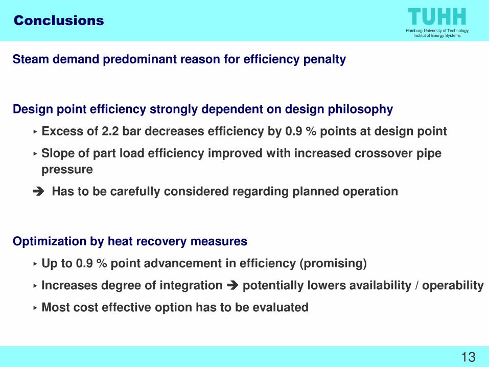
Steam demand predominant reason for efficiency penalty
Design point efficiency strongly dependent on design philosophy
▸ Excess of 2.2 bar decreases efficiency by 0.9 % points at design point
▸ Slope of part load efficiency improved with increased crossover pipe
pressure
���� Has to be carefully considered regarding planned operation
Optimization by heat recovery measures
▸ Up to 0.9 % point advancement in efficiency (promising)
▸ Increases degree of integration ���� potentially lowers availability / operability
▸Most cost effective option has to be evaluated
13
Hamburg University of Technology
Institut of Energy Systems
Thank you for your attention!
Imo Pfaff - [email protected]
Institute of Energy Systems
14

Hamburg University of Technology
Institut of Energy Systems
Advanced Combustion Air Pre-heat Configuration
APHSec. I
APHSec. II
Feedwater-heater
Tem
per
atur e
Configuration without bypass
Available temperature level of
flue gas bypass
(mass flow determines the heat
available)
15
Sec. II
Air Heater
(steam/waste
heat)
APH Sec I APH Sec II
TransferredHeat
Combustion Air
without bypass
Waste Heat Input
Constant flue gas temperature