intel 8086 assembler - apache2 debian default page: it …robbe/thesis/doc/intel 8086...
TRANSCRIPT
Intel 8086 Assemblerver. 7
Computersystems 2012-2013
Prof. Peter SchelkensTim BruylantsBob Andries
Pag.
What is Assembly Language?
• Native language of the machine• Processor understands only machine code (i.e. specific
combinations of 0’s and 1’s)• Assembly Language helps writing this machine code via use of
mnemonics (i.e. English-like words that map to the various machine instructions)
• The assembler converts mnemonics into 0’s and 1’s
Computersystemen 2012-2013 2
Pag.
Machine vs Assembly Code
Computersystemen 2012-2013
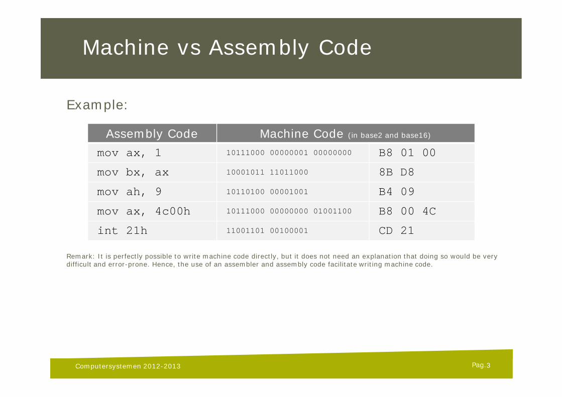
Example:
Remark: It is perfectly possible to write machine code directly, but it does not need an explanation that doing so would be verydifficult and error-prone. Hence, the use of an assembler and assembly code facilitate writing machine code.
Assembly Code Machine Code (in base2 and base16)
mov ax, 1 10111000 00000001 00000000 B8 01 00
mov bx, ax 10001011 11011000 8B D8
mov ah, 9 10110100 00001001 B4 09
mov ax, 4c00h 10111000 00000000 01001100 B8 00 4C
int 21h 11001101 00100001 CD 21
3
Pag.
Assembler and Linker Tools
• Assembling code will be done using MASM v6.1 (Microsoft Assembler)
• MASM creates machine code in .OBJ files• every .ASM file is translated into an .OBJ file• A .ASM file is a human readable text file with instructions (the source code)• A .OBJ file is a binary (less human-readable) file
• The linker (LINK) combines one or more .OBJ files into a DOS .EXE executable file
• EXE files are stand-alone self-provisioning programs that can be started by the operating system (DOS)
Computersystemen 2012-2013 4
Pag.
MASM and LINK
Computersystemen 2012-2013
Example:masm mycode.asmlink mycode.obj,myprog.exe,,,,myprog.exe
Line 1 assembles the assembly source code into machine code (instructions and data).Line 2 creates the DOS executable from the machine code object file (apply structure for the operating system).Line 3 tells the OS to run the program.
5
Pag.
DOSBox
• For this course we will run everything inside DOSBox• DOSBox is 8086 CPU emulation environment (i.e. it completely
emulates typical IBM-compatible PC from the ’80s) with a built in DOS emulation
• This is convenient, because:• It protects you from messing up your PC• It allows running 8086 DOS programs on modern systems• The 8086 based PC is far less complex than the modern
computers of today (or even a smartphone)
Computersystemen 2012-2013 6
Pag.
Debugging
• Debugging is the activity of locating and fixing bugs in a program• A debugger is a tool that facilitates the programmer debugging a
program• MASM v6.1 comes with a debug tool, called CV• Typically, a debug tool allows
• stepping through code instruction by instruction• placing breakpoints (a point at which the CPU should halt code execution)• displaying and modifying memory contents at any time• displaying and modifying CPU register contents• modifying code while the program runs
• Use the debugger! It helps!
Computersystemen 2012-2013 7
Pag.
The 8086 CPU
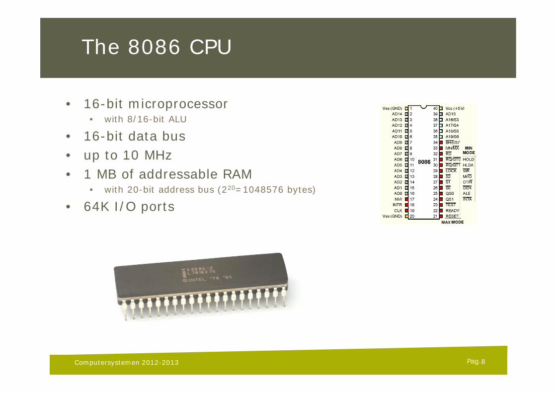
• 16-bit microprocessor• with 8/16-bit ALU
• 16-bit data bus• up to 10 MHz• 1 MB of addressable RAM
• with 20-bit address bus (220=1048576 bytes)
• 64K I/O ports
Computersystemen 2012-2013 8
Pag.
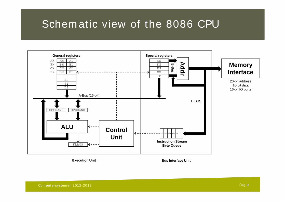
Schematic view of the 8086 CPU
Computersystemen 2012-2013
Special registers
DSESSSIP
CSAH ALBH BLCH CLDH DL
SPBPSIDI
General registersAXBXCXDX
OPERAND OPERAND
ALU
A-Bus (16-bit)
FLAGS
ControlUnit
654321
Instruction StreamByte Queue
Addr
MemoryInterface
C-Bus
B-B
us
20-bit address16-bit data
16-bit IO ports
Execution Unit Bus Interface Unit
9
Pag.
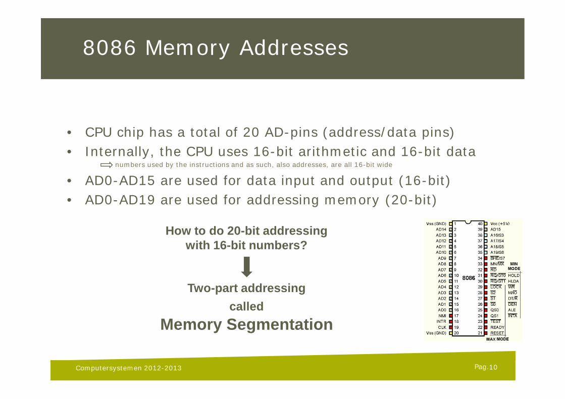
8086 Memory Addresses
• CPU chip has a total of 20 AD-pins (address/data pins)• Internally, the CPU uses 16-bit arithmetic and 16-bit data
numbers used by the instructions and as such, also addresses, are all 16-bit wide
• AD0-AD15 are used for data input and output (16-bit)• AD0-AD19 are used for addressing memory (20-bit)
Computersystemen 2012-2013
Two-part addressingcalled
Memory Segmentation
How to do 20-bit addressingwith 16-bit numbers?
10
Pag.
Memory segmentation
• Memory segmentation is a design trick where the CPU uses compound addresses
• With 20-bit addressable memory space a total capacity of 1MB can be used• The 1MB memory space is divided into 216 (= 65536) overlapping segments• Every segment block comprises 216 (=65536) bytes
• The 20-bit address is represented by two 16-bit values• One value is called the SEGMENT (16-bit value)• One value is called the OFFSET (16-bit value)
• 20-bit effective (or physical or absolute) address (EA) is generated by the ADDR logic in the CPU
EA = segment x 16 + offset
Computersystemen 2012-2013 11
Pag.
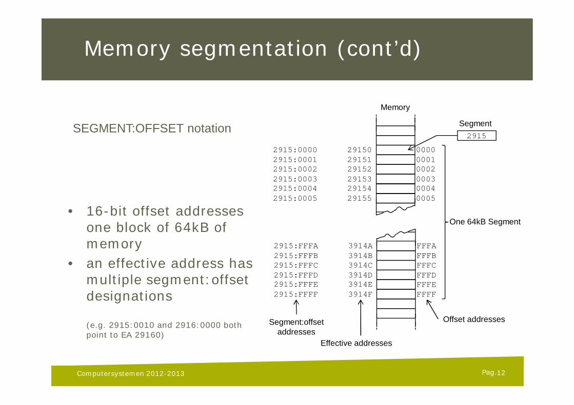
Memory segmentation (cont’d)
• 16-bit offset addresses one block of 64kB of memory
• an effective address has multiple segment:offsetdesignations
(e.g. 2915:0010 and 2916:0000 both point to EA 29160)
Computersystemen 2012-2013
000000010002000300040005
FFFAFFFBFFFCFFFDFFFEFFFF
2915
Segment
Memory
One 64kB Segment
Offset addresses
291502915129152291532915429155
3914A3914B3914C3914D3914E3914F
Effective addresses
2915:00002915:00012915:00022915:00032915:00042915:0005
2915:FFFA2915:FFFB2915:FFFC2915:FFFD2915:FFFE2915:FFFF
Segment:offsetaddresses
SEGMENT:OFFSET notation
12
Pag.
8086 Registers
• 16-bit storage variables (i.e. small internal memory)• located inside the CPU chip• extremely fast accessible (read and write)• 8086 has a total of 14 accessible registers• all designated with unique names and abbreviations
• AX, BX, CX and DX• CS, DS, ES and SS• IP and FLAGS• BP, SP, SI and DI
Computersystemen 2012-2013 13
Pag.
8086 Registers (cont’d)
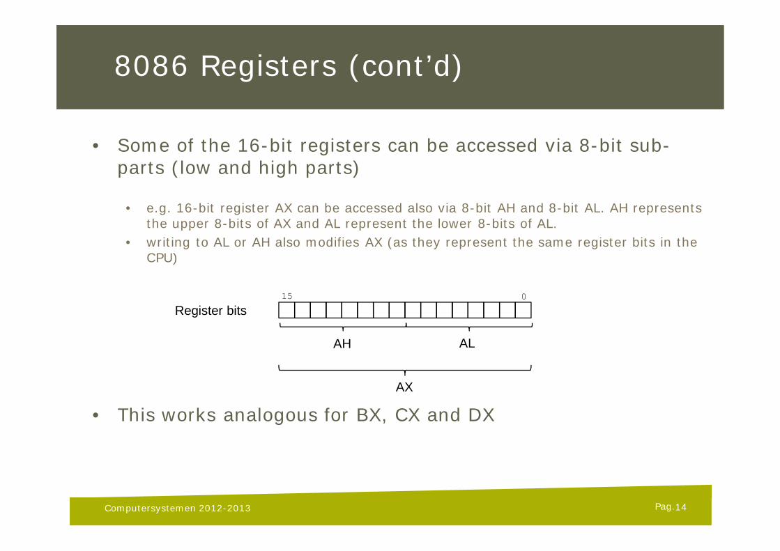
• Some of the 16-bit registers can be accessed via 8-bit sub-parts (low and high parts)
• e.g. 16-bit register AX can be accessed also via 8-bit AH and 8-bit AL. AH represents the upper 8-bits of AX and AL represent the lower 8-bits of AL.
• writing to AL or AH also modifies AX (as they represent the same register bits in the CPU)
• This works analogous for BX, CX and DX
14Computersystemen 2012-2013
15 0
Register bits
AH AL
AX
Pag.
General purpose registers
AX - Accumulator register (divided in AH/AL)1. Generates shortest machine code2. Arithmetic, logic and data transfer3. One number must be in AL or AX4. Multiplication & Division5. Input & Output
BX - Base address register (divided in BH/BL)1. Can be used in various memory addressing instructions
Computersystemen 2012-2013 15
Pag.
General purpose registers
CX - Count register (divided in CH/CL)1. Iterative code segments using the LOOP instruction2. Repetitive operations on strings with the REP command3. Count (in CL) of bits to shift and rotate
DX - Data register (divided in DH/DL)1. DX:AX concatenated into 32-bit register for some MUL and
DIV operations2. Specifying ports in some IN and OUT operations
Computersystemen 2012-2013 16
Pag.
General purpose registers
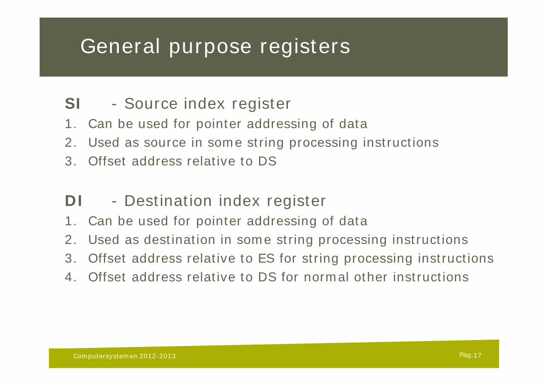
SI - Source index register1. Can be used for pointer addressing of data2. Used as source in some string processing instructions3. Offset address relative to DS
DI - Destination index register1. Can be used for pointer addressing of data2. Used as destination in some string processing instructions3. Offset address relative to ES for string processing instructions4. Offset address relative to DS for normal other instructions
Computersystemen 2012-2013 17
Pag.
General purpose registers
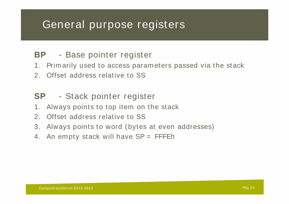
BP - Base pointer register1. Primarily used to access parameters passed via the stack2. Offset address relative to SS
SP - Stack pointer register1. Always points to top item on the stack2. Offset address relative to SS3. Always points to word (bytes at even addresses)4. An empty stack will have SP = FFFEh
Computersystemen 2012-2013 18
Pag.
Segment registers
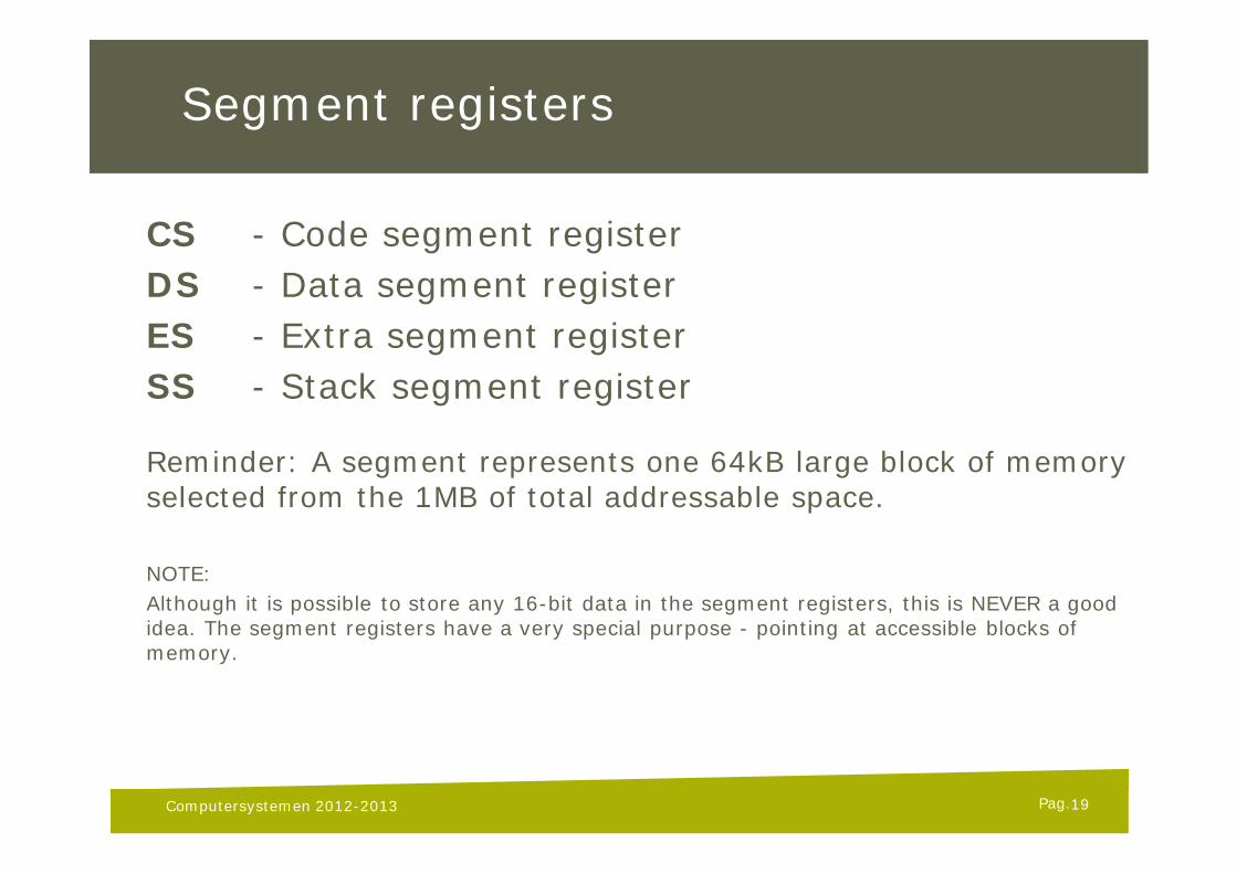
CS - Code segment registerDS - Data segment registerES - Extra segment registerSS - Stack segment register
Reminder: A segment represents one 64kB large block of memory selected from the 1MB of total addressable space.
NOTE:Although it is possible to store any 16-bit data in the segment registers, this is NEVER a good idea. The segment registers have a very special purpose - pointing at accessible blocks of memory.
Computersystemen 2012-2013 19
Pag.
Segment registers (cont’d)
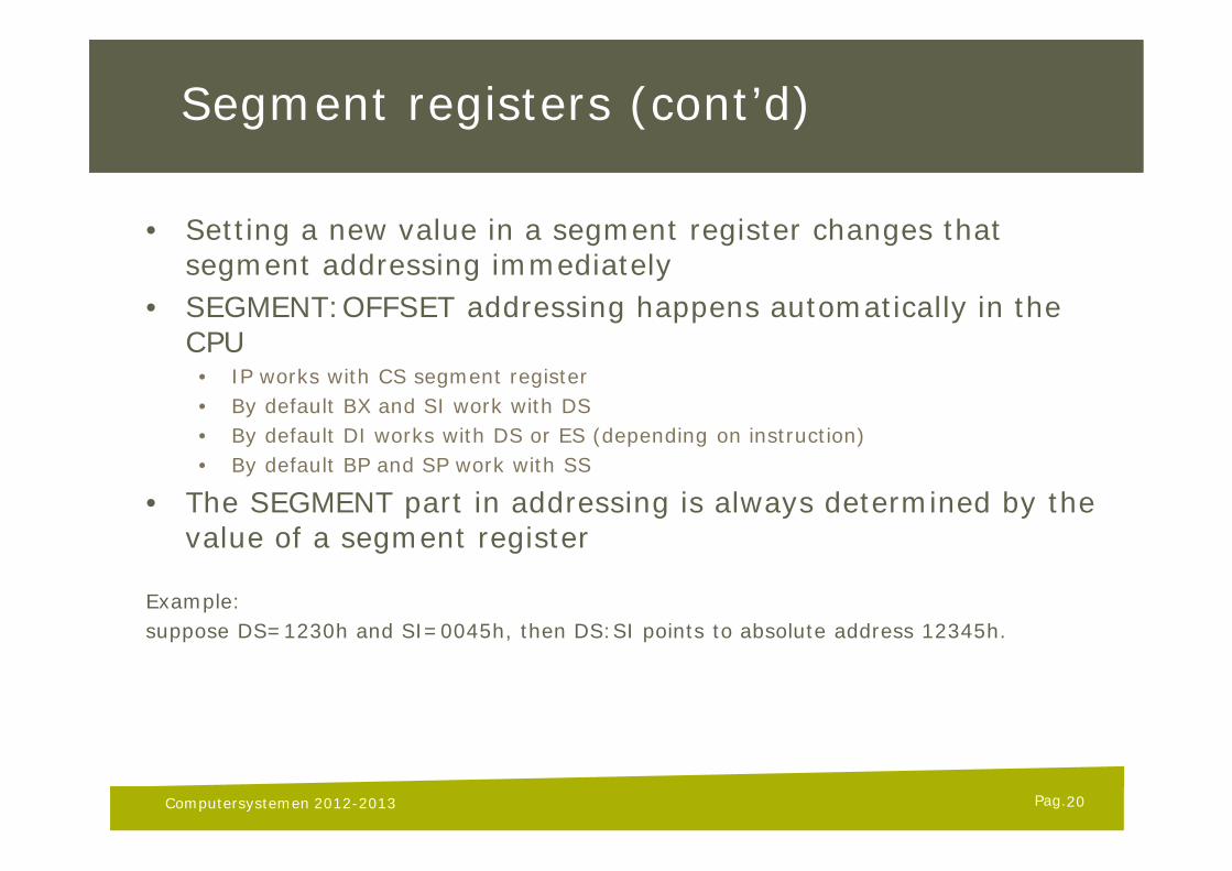
• Setting a new value in a segment register changes that segment addressing immediately
• SEGMENT:OFFSET addressing happens automatically in the CPU
• IP works with CS segment register• By default BX and SI work with DS• By default DI works with DS or ES (depending on instruction)• By default BP and SP work with SS
• The SEGMENT part in addressing is always determined by the value of a segment register
Example:suppose DS=1230h and SI=0045h, then DS:SI points to absolute address 12345h.
Computersystemen 2012-2013 20
Pag.
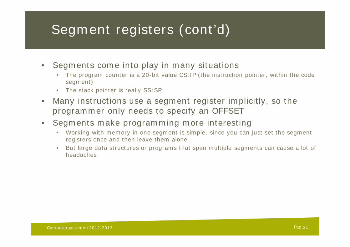
Segment registers (cont’d)
• Segments come into play in many situations• The program counter is a 20-bit value CS:IP (the instruction pointer, within the code
segment)• The stack pointer is really SS:SP
• Many instructions use a segment register implicitly, so the programmer only needs to specify an OFFSET
• Segments make programming more interesting• Working with memory in one segment is simple, since you can just set the segment
registers once and then leave them alone• But large data structures or programs that span multiple segments can cause a lot of
headaches
Computersystemen 2012-2013 21
Pag.
Special purpose registers
IP - Instruction pointer register1. Always points to next instruction to be executed2. Offset address relative to CS
The IP register always works together with the CS segment register, pointing to the next instruction to be executed.
Computersystemen 2012-2013 22
Pag.
Flags register
• A 16-bit register• A flag represents a binary state (0 or 1)• Thus, each bit represents a single flag• The 16 flag bits represent the current state of specific parts of
the processor• Flags are modified by ALU automatically• Used for program flow control and condition checking• Not directly accessible
23Computersystemen 2012-2013
Pag.
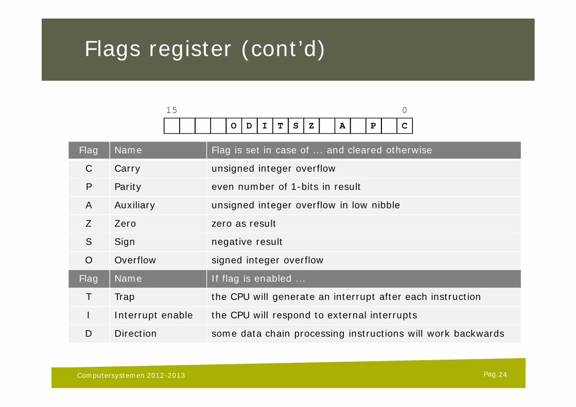
Flags register (cont’d)
Computersystemen 2012-2013
O D I T S Z A P C
15 0
Flag Name Flag is set in case of ... and cleared otherwise
C Carry unsigned integer overflow
P Parity even number of 1-bits in result
A Auxiliary unsigned integer overflow in low nibble
Z Zero zero as result
S Sign negative result
O Overflow signed integer overflow
Flag Name If flag is enabled ...
T Trap the CPU will generate an interrupt after each instruction
I Interrupt enable the CPU will respond to external interrupts
D Direction some data chain processing instructions will work backwards
24
Pag.
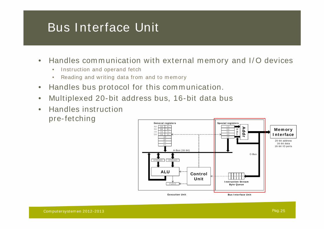
Bus Interface Unit
• Handles communication with external memory and I/O devices• Instruction and operand fetch• Reading and writing data from and to memory
• Handles bus protocol for this communication.• Multiplexed 20-bit address bus, 16-bit data bus• Handles instruction
pre-fetching
25Computersystemen 2012-2013
Special registers
DSESSSIP
CSAH ALBH BLCH CLDH DL
SPBPSIDI
General registersAXBXCXDX
OPERAND OPERAND
ALU
A-Bus (16-bit)
FLAGS
ControlUnit
654321
Instruction StreamByte Queue
Ad
dr
MemoryInterface
C-Bus
B-B
us
20-bit address16-bit data
16-bit IO ports
Execution Unit Bus Interface Unit
Pag.
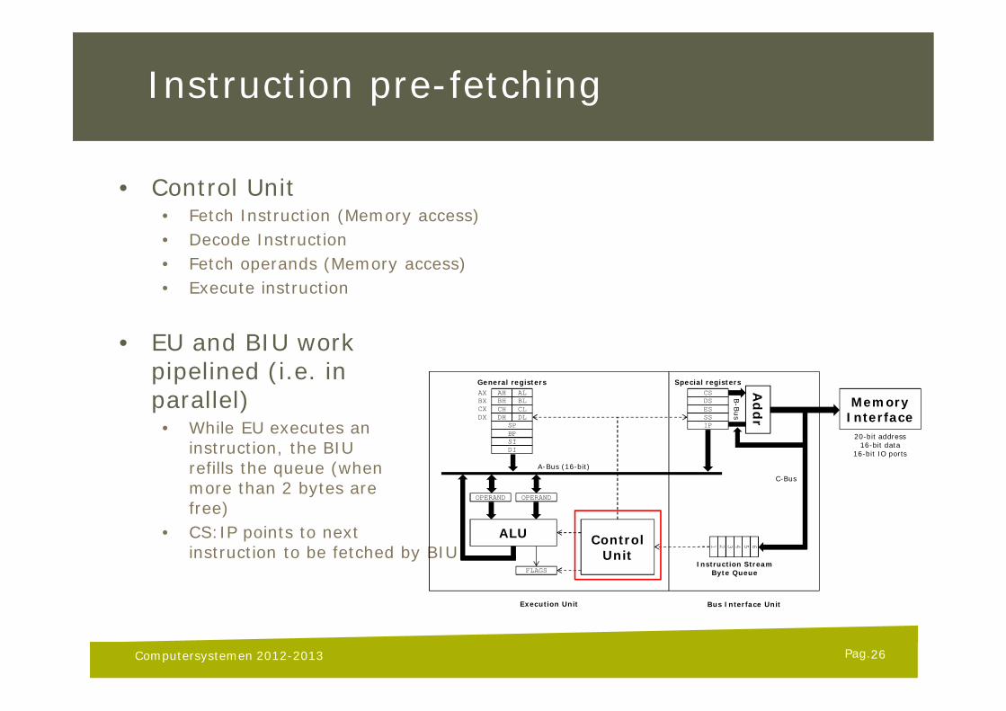
Instruction pre-fetching
• Control Unit• Fetch Instruction (Memory access)• Decode Instruction• Fetch operands (Memory access)• Execute instruction
• EU and BIU workpipelined (i.e. inparallel)
• While EU executes aninstruction, the BIUrefills the queue (whenmore than 2 bytes arefree)
• CS:IP points to nextinstruction to be fetched by BIU
26Computersystemen 2012-2013
Special registers
DSESSSIP
CSAH ALBH BLCH CLDH DL
SPBPSIDI
General registersAXBXCXDX
OPERAND OPERAND
ALU
A-Bus (16-bit)
FLAGS
ControlUnit
654321
Instruction StreamByte Queue
Ad
dr
MemoryInterface
C-Bus
B-B
us
20-bit address16-bit data
16-bit IO ports
Execution Unit Bus Interface Unit
Pag.
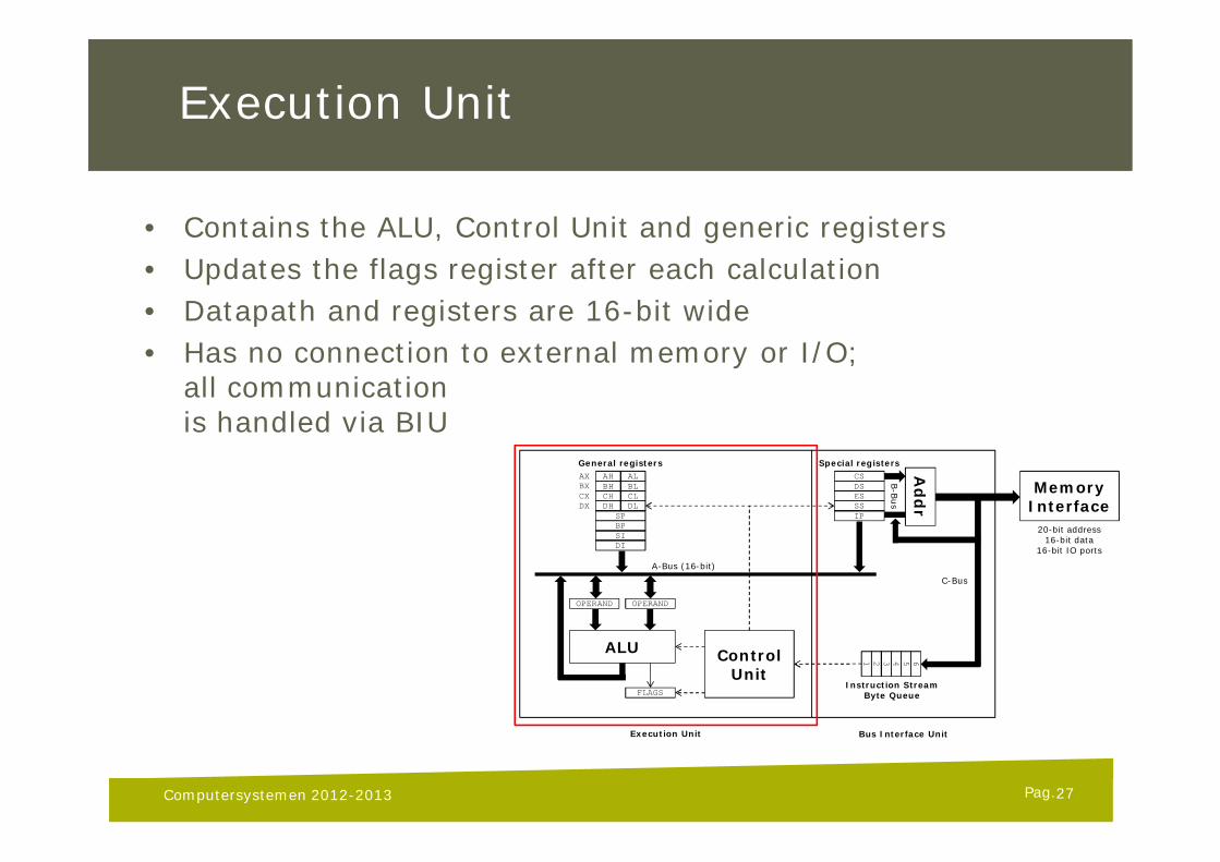
Execution Unit
• Contains the ALU, Control Unit and generic registers• Updates the flags register after each calculation• Datapath and registers are 16-bit wide• Has no connection to external memory or I/O;
all communicationis handled via BIU
27Computersystemen 2012-2013
Special registers
DSESSSIP
CSAH ALBH BLCH CLDH DL
SPBPSIDI
General registersAXBXCXDX
OPERAND OPERAND
ALU
A-Bus (16-bit)
FLAGS
ControlUnit
654321
Instruction StreamByte Queue
Add
r
MemoryInterface
C-Bus
B-B
us
20-bit address16-bit data
16-bit IO ports
Execution Unit Bus Interface Unit
Pag.
Continuous Execution
• From power-on, the CPU starts fetching instructions from memory and executing them
• This never stops, unless power is turned off• Various categories of instructions exist:
• Data move instructions (MOV, STOSB, ...)• Branch instructions (JMP, JZ, CALL, JGE, ...)• Arithmetic instruction (ADD, MUL, SUB, INC, ...)
• For a comprehensive set of instruction, refer to:• The MASM v6.1 manual• The Art of Assembly Language Programming, Chapter 6• Google
• Note: we will allow ONLY 8086 or 8087 instructions!
28Computersystemen 2012-2013
Pag.
Memory addressing modes
• Many instructions can access memory to read/write data• e.g. MOV, ADD, ... (see instruction set reference)
• Addressing modes are the various ways to do so• 8086 has 17 valid memory addressing modes
• All 17 modes fit into one of the following categories:
• Displacement only• Register indirect• Indexed• Based indexed• Based indexed with displacement
29Computersystemen 2012-2013
Pag.
Memory addressing modes (2)
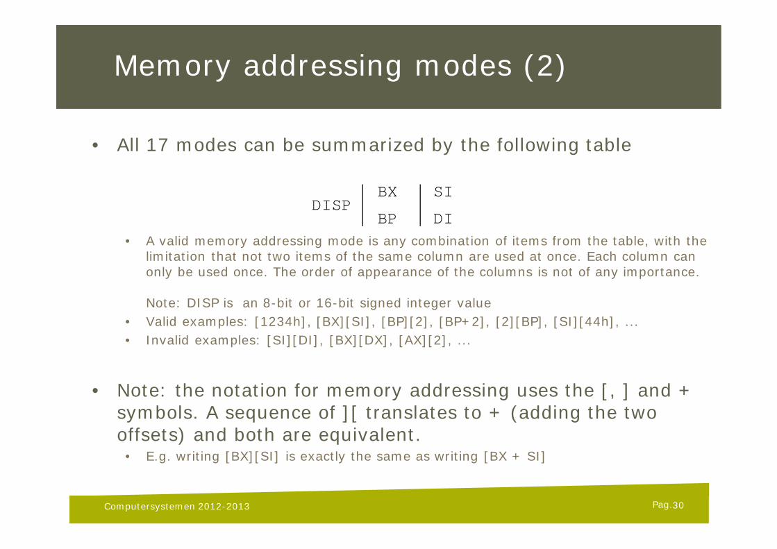
• All 17 modes can be summarized by the following table
• A valid memory addressing mode is any combination of items from the table, with the limitation that not two items of the same column are used at once. Each column can only be used once. The order of appearance of the columns is not of any importance.
Note: DISP is an 8-bit or 16-bit signed integer value• Valid examples: [1234h], [BX][SI], [BP][2], [BP+2], [2][BP], [SI][44h], ...• Invalid examples: [SI][DI], [BX][DX], [AX][2], ...
• Note: the notation for memory addressing uses the [, ] and + symbols. A sequence of ][ translates to + (adding the two offsets) and both are equivalent.
• E.g. writing [BX][SI] is exactly the same as writing [BX + SI]
30Computersystemen 2012-2013
DISPBX SI
BP DI
Pag.
Memory addressing modes (3)
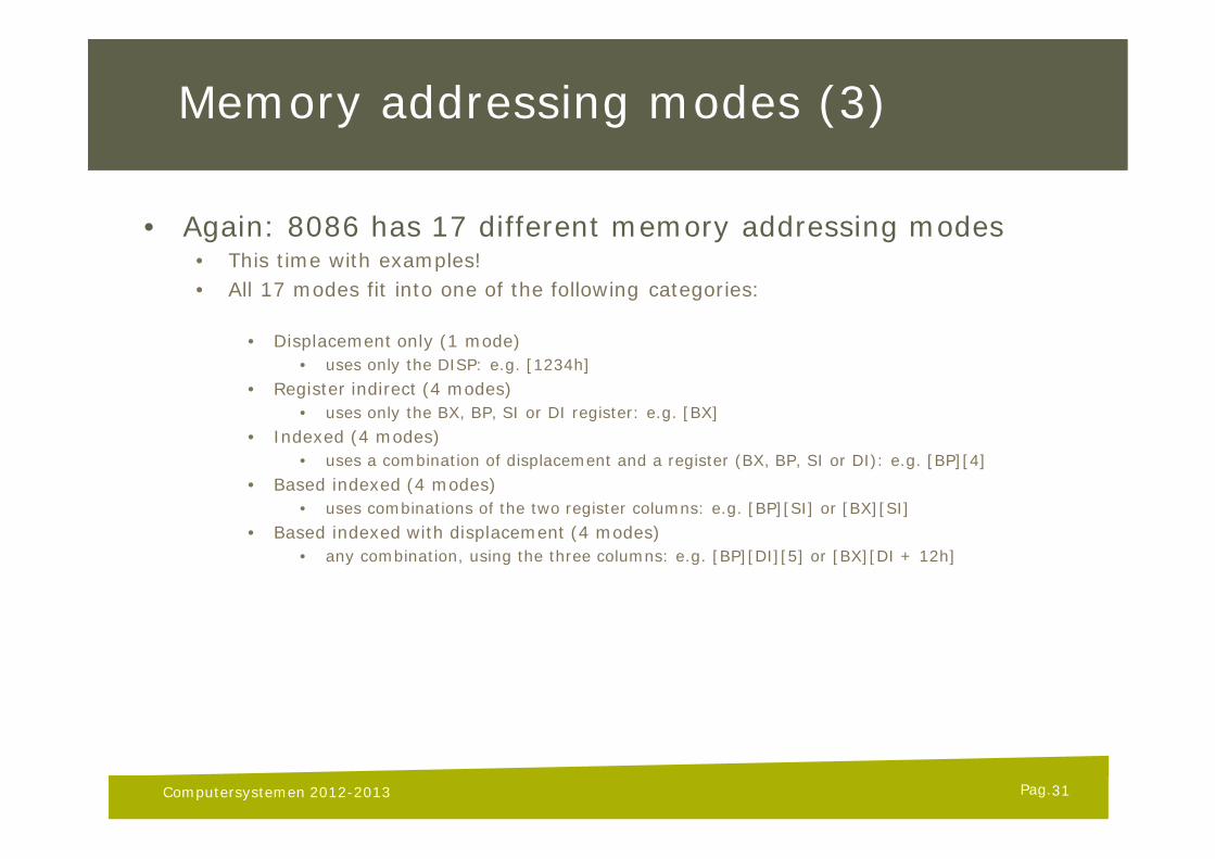
• Again: 8086 has 17 different memory addressing modes• This time with examples!• All 17 modes fit into one of the following categories:
• Displacement only (1 mode)• uses only the DISP: e.g. [1234h]
• Register indirect (4 modes)• uses only the BX, BP, SI or DI register: e.g. [BX]
• Indexed (4 modes)• uses a combination of displacement and a register (BX, BP, SI or DI): e.g. [BP][4]
• Based indexed (4 modes)• uses combinations of the two register columns: e.g. [BP][SI] or [BX][SI]
• Based indexed with displacement (4 modes)• any combination, using the three columns: e.g. [BP][DI][5] or [BX][DI + 12h]
31Computersystemen 2012-2013
Pag.
Memory addressing modes (4)
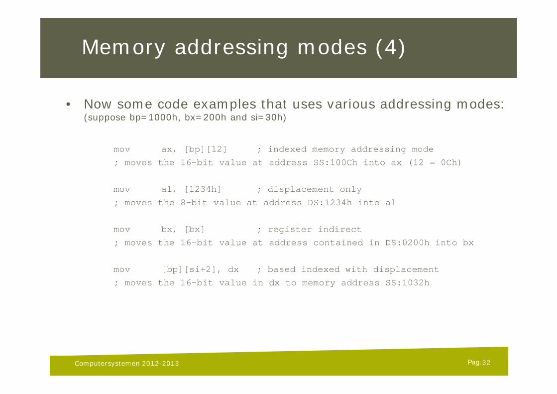
• Now some code examples that uses various addressing modes:(suppose bp=1000h, bx=200h and si=30h)
mov ax, [bp][12] ; indexed memory addressing mode
; moves the 16-bit value at address SS:100Ch into ax (12 = 0Ch)
mov al, [1234h] ; displacement only
; moves the 8-bit value at address DS:1234h into al
mov bx, [bx] ; register indirect
; moves the 16-bit value at address contained in DS:0200h into bx
mov [bp][si+2], dx ; based indexed with displacement
; moves the 16-bit value in dx to memory address SS:1032h
Computersystemen 2012-2013 32
Pag.
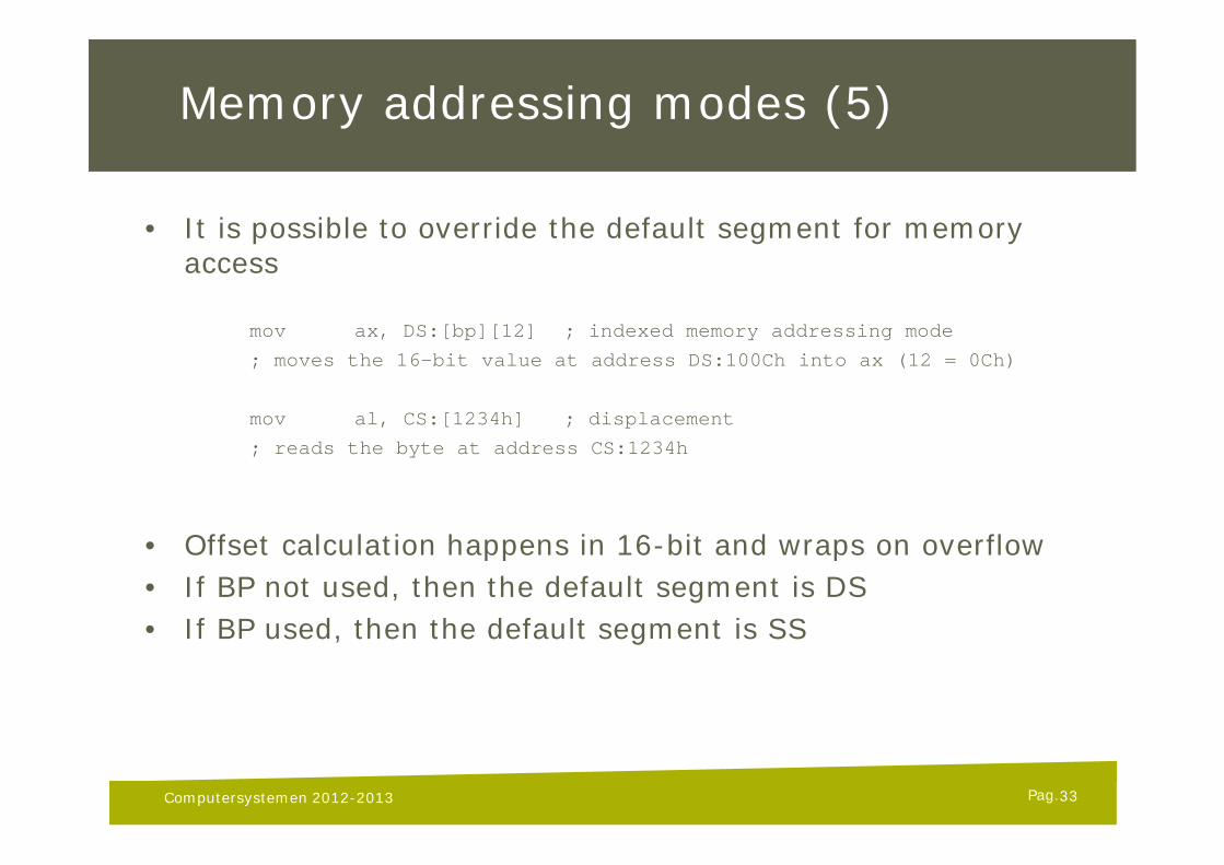
Memory addressing modes (5)
• It is possible to override the default segment for memory access
mov ax, DS:[bp][12] ; indexed memory addressing mode
; moves the 16-bit value at address DS:100Ch into ax (12 = 0Ch)
mov al, CS:[1234h] ; displacement
; reads the byte at address CS:1234h
• Offset calculation happens in 16-bit and wraps on overflow• If BP not used, then the default segment is DS• If BP used, then the default segment is SS
Computersystemen 2012-2013 33
Pag.
8086 Stack Segment
• Just another memory segment (like CS, DS and ES)• Accessed through SS segment register• Memory segment specifically used for stack operations• Dedicated set of instructions work exclusively with the stack
• i.e. PUSH, POP, RET, CALL, INT, ...
• Stack memory works top-down• Often used for function call handling and parameter passing• PUSH <reg>
decreases SP with 2 and then writes the content of reg to memory address SS:SP
• POP <reg>reads the content at memory address SS:SP into reg and increments SP with 2
Computersystemen 2012-2013 34
Pag.
Jump instructions
• Special type of instructions that change IP register and optionally also CS register
• Unconditional jump instructions (always jump if executed):• JMP NEAR PTR label ; jumps to label
• JMP WORD PTR [BX] ; jumps to address in BX
• JMP FAR PTR label ; far jump to label
• JMP DWORD PTR [BX] ; far jump to [BX]:[BX+2]
• JMP SHORT label ; jumps to label (within -128 to +127 bytes)
• SHORT and NEAR jumps only change IP register• FAR jumps change both CS and IP registers• SHORT jumps can only jump short distances ([-128; 127] bytes range), but generate
shorter machine instructions• Assembler usually selects shortest jump instruction when typing JMP label
35Computersystemen 2012-2013
Pag.
Jump instructions (cont’d)
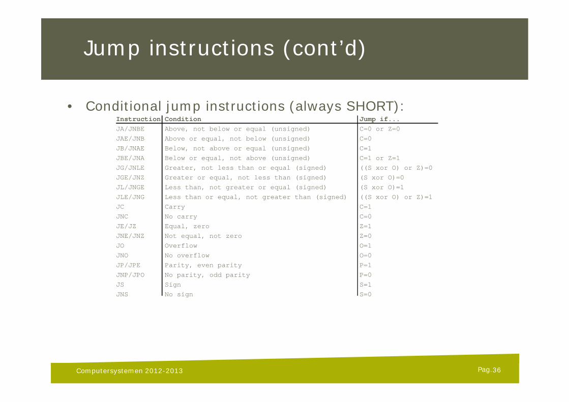
• Conditional jump instructions (always SHORT):Instruction Condition Jump if...JA/JNBE Above, not below or equal (unsigned) C=0 or Z=0
JAE/JNB Above or equal, not below (unsigned) C=0
JB/JNAE Below, not above or equal (unsigned) C=1
JBE/JNA Below or equal, not above (unsigned) C=1 or Z=1
JG/JNLE Greater, not less than or equal (signed) ((S xor O) or Z)=0
JGE/JNZ Greater or equal, not less than (signed) (S xor O)=0
JL/JNGE Less than, not greater or equal (signed) (S xor O)=1
JLE/JNG Less than or equal, not greater than (signed) ((S xor O) or Z)=1
JC Carry C=1
JNC No carry C=0
JE/JZ Equal, zero Z=1
JNE/JNZ Not equal, not zero Z=0
JO Overflow O=1
JNO No overflow O=0
JP/JPE Parity, even parity P=1
JNP/JPO No parity, odd parity P=0
JS Sign S=1
JNS No sign S=0
Computersystemen 2012-2013 36
Pag.
Example: Jumping
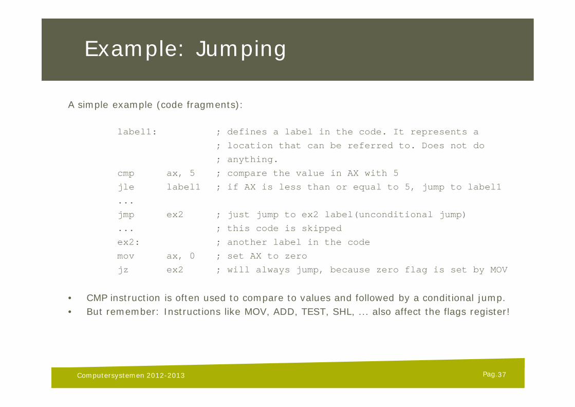
A simple example (code fragments):
label1: ; defines a label in the code. It represents a
; location that can be referred to. Does not do
; anything.
cmp ax, 5 ; compare the value in AX with 5
jle label1 ; if AX is less than or equal to 5, jump to label1
...
jmp ex2 ; just jump to ex2 label(unconditional jump)
... ; this code is skipped
ex2: ; another label in the code
mov ax, 0 ; set AX to zero
jz ex2 ; will always jump, because zero flag is set by MOV
• CMP instruction is often used to compare to values and followed by a conditional jump.• But remember: Instructions like MOV, ADD, TEST, SHL, ... also affect the flags register!
Computersystemen 2012-2013 37
Pag.
Function calling
• Handled with the CALL and RET/RETF instructions• A near CALL can be interpreted as a “PUSH IP + JMP NEAR” instruction• A far CALL can be interpreted as a “PUSH CS + PUSH IP + JMP FAR” instruction
• RET is used to return from the function and continue execution just after the CALL• A RET can be interpreted as a “POP IP + JUMP” instruction (near)• A RETF can be interpreted as a “POP IP + POP CS + JUMP” instruction (far)
• Use RET with near calls and RETF with far calls
• RET/RETF can specify an extra optional even immediate that adjusts the stack pointer (SP = SP + imm) after returning
• Note: CALL and RET do the push/pop and jump in one atomic step!
Computersystemen 2012-2013 38
Pag.
Example: Simple functions
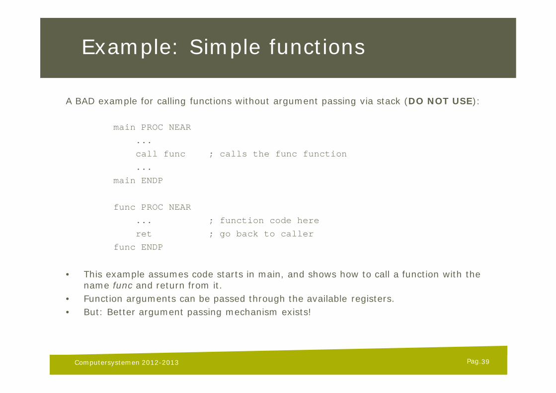
A BAD example for calling functions without argument passing via stack (DO NOT USE):
main PROC NEAR
...
call func ; calls the func function
...
main ENDP
func PROC NEAR
... ; function code here
ret ; go back to caller
func ENDP
• This example assumes code starts in main, and shows how to call a function with the name func and return from it.
• Function arguments can be passed through the available registers.• But: Better argument passing mechanism exists!
Computersystemen 2012-2013 39
Pag.
Stack-based arguments
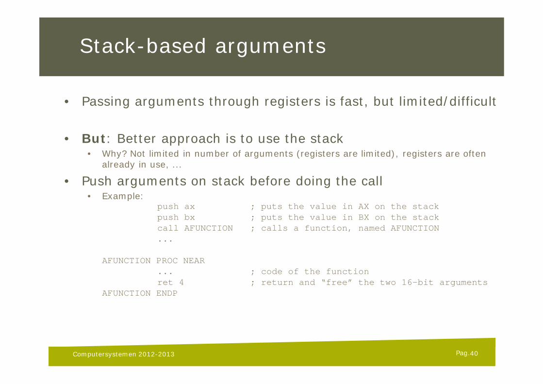
• Passing arguments through registers is fast, but limited/difficult
• But: Better approach is to use the stack• Why? Not limited in number of arguments (registers are limited), registers are often
already in use, ...
• Push arguments on stack before doing the call• Example:
push ax ; puts the value in AX on the stackpush bx ; puts the value in BX on the stackcall AFUNCTION ; calls a function, named AFUNCTION...
AFUNCTION PROC NEAR... ; code of the functionret 4 ; return and “free” the two 16-bit arguments
AFUNCTION ENDP
Computersystemen 2012-2013 40
Pag.
Stack-based arguments (2)
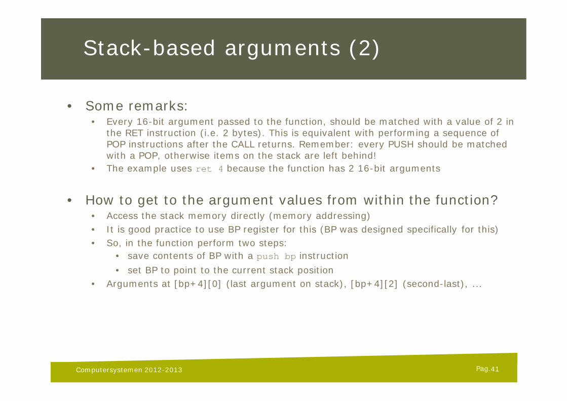
• Some remarks:• Every 16-bit argument passed to the function, should be matched with a value of 2 in
the RET instruction (i.e. 2 bytes). This is equivalent with performing a sequence of POP instructions after the CALL returns. Remember: every PUSH should be matched with a POP, otherwise items on the stack are left behind!
• The example uses ret 4 because the function has 2 16-bit arguments
• How to get to the argument values from within the function?• Access the stack memory directly (memory addressing)• It is good practice to use BP register for this (BP was designed specifically for this)• So, in the function perform two steps:
• save contents of BP with a push bp instruction• set BP to point to the current stack position
• Arguments at [bp+4][0] (last argument on stack), [bp+4][2] (second-last), ...
Computersystemen 2012-2013 41
Pag.
Stack-based arguments (3)
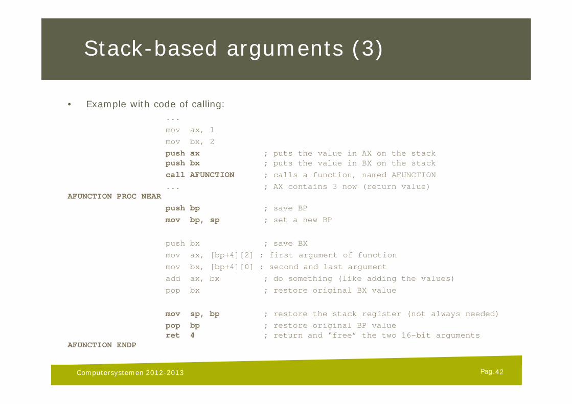
• Example with code of calling:...
mov ax, 1
mov bx, 2
push ax ; puts the value in AX on the stackpush bx ; puts the value in BX on the stack
call AFUNCTION ; calls a function, named AFUNCTION
... ; AX contains 3 now (return value)AFUNCTION PROC NEAR
push bp ; save BP
mov bp, sp ; set a new BP
push bx ; save BX
mov ax, [bp+4][2] ; first argument of function
mov bx, [bp+4][0] ; second and last argument
add ax, bx ; do something (like adding the values)
pop bx ; restore original BX value
mov sp, bp ; restore the stack register (not always needed)
pop bp ; restore original BP valueret 4 ; return and “free” the two 16-bit arguments
AFUNCTION ENDP
Computersystemen 2012-2013 42
Pag.
Stack-based arguments (4)
• Some more remarks:• Why pushing registers that are used in the function (like push bx)?
Because a function should save all registers that it modifies, except for AX when returning a value! A function is always called from some running code, and you don’t want to break the state of the program. E.g. calling a function inside a loop. A typical loop uses CX. If the function would change the CX value, then bad things can happen!
• Why the push bp?Because the BP register is modified by the function. (See previous question.)
• Why the [bp+4] when accessing argument?Because BP points to SP at the time that the stack contains the arguments followed by the return address (put there by the call instruction) and the just pushed BP value. These two extra values amount to two 16-bit values, or 4 bytes.Note: FAR functions must also account for the extra CS on the stack, so accessing arguments resolves to [bp+6] (one extra 16-bit value)!
43Computersystemen 2012-2013
Pag.
Stack-based local variables
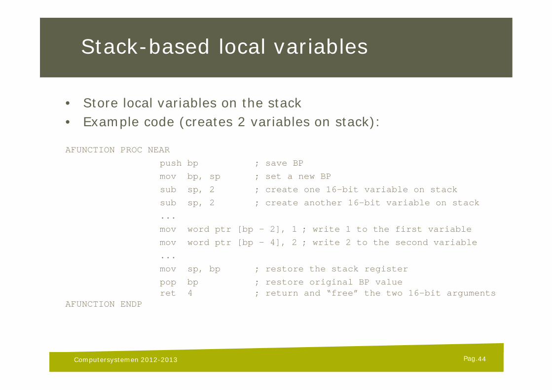
• Store local variables on the stack• Example code (creates 2 variables on stack):
AFUNCTION PROC NEAR
push bp ; save BP
mov bp, sp ; set a new BP
sub sp, 2 ; create one 16-bit variable on stack
sub sp, 2 ; create another 16-bit variable on stack
...
mov word ptr [bp – 2], 1 ; write 1 to the first variable
mov word ptr [bp – 4], 2 ; write 2 to the second variable
...
mov sp, bp ; restore the stack register
pop bp ; restore original BP valueret 4 ; return and “free” the two 16-bit arguments
AFUNCTION ENDP
Computersystemen 2012-2013 44
Pag.
Interrupts
• An interrupt immediately pauses the current program flow and executes a respective special function, called interrupt handler
• Can happen at any time, during execution of any program/code• Interrupts are classified with an 8-bit value (0-255)• Interrupts and their associated interrupt handlers exist to
process special events (e.g. divide by zero, user key press, timer event, ...)
• Interrupts can be triggered by:• CPU internally (divide by zero, memory errors, ...)• external hardware (via special pins on the CPU)• software (by the int instruction in code)
Computersystemen 2012-2013 45
Pag.
Interrupts (2)
• Interrupt causes execution of user-defined code• Maskable interrupts can be turned on and off (via STI/CLI instructions, that basically
set and clear the I (interrupt enable) flag in the flags register)• Non-maskable interrupts can not be blocked (e.g. memory parity error)
• An interrupt handler is similar to a function, but:• Flags are also pushed on the stack, so it uses iret to return (pops the flags)• Is always of type far (thus CS and IP are pushed)• Blocks other maskable interrupts from occurring (STI/CLI instructions) to prevent
interrupts in interrupts (endless loops)• On hardware and CPU interrupts, both the T and I flags are cleared
Computersystemen 2012-2013 46
Pag.
Interrupts (3)
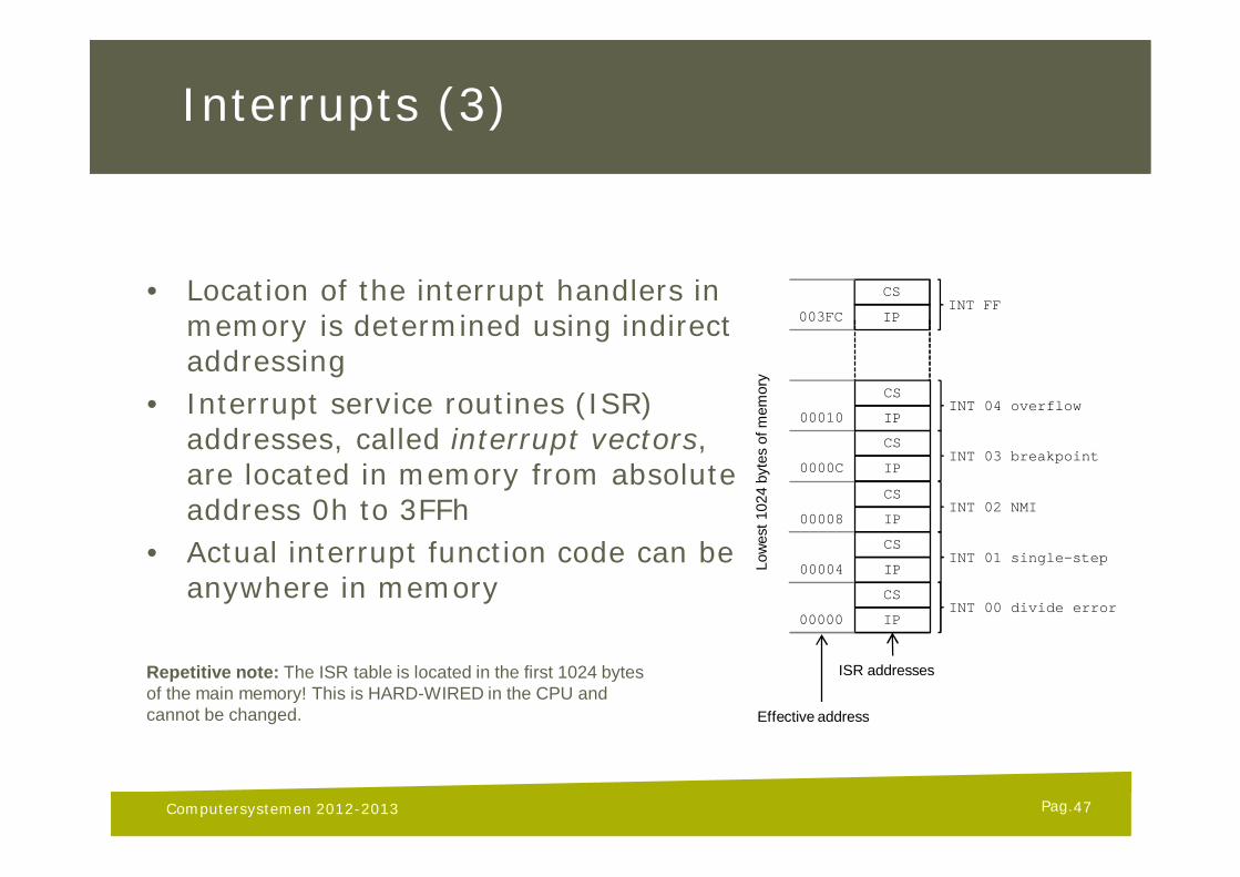
• Location of the interrupt handlers in memory is determined using indirect addressing
• Interrupt service routines (ISR) addresses, called interrupt vectors, are located in memory from absolute address 0h to 3FFh
• Actual interrupt function code can be anywhere in memory
Computersystemen 2012-2013
CS
IPINT FF
003FC
CS
IPINT 00 divide error
00000
CS
IPINT 01 single-step
00004
CS
IPINT 02 NMI
00008
CS
IPINT 03 breakpoint
0000C
CS
IPINT 04 overflow
00010
ISR addresses
Effective address
Low
est 1
024
byte
s of
mem
ory
Repetitive note: The ISR table is located in the first 1024 bytesof the main memory! This is HARD-WIRED in the CPU andcannot be changed.
47
Pag.
Interrupts (4)
• E.g. external hardware interrupt is handled as follows:• I/O Interface sends interrupt signal• Acknowledge interrupt signal after current instruction is completed• Interface communicates interrupt number (i)• Current flag register, CS register and IP are pushed on the stack• I and T flags cleared (this blocks other external interrupts)• CPU sets IP=[4*i] and CS=[4*i+2]• Execution of interrupt handler begins• IRET (return from interrupt), restores Flag register, IP and CS form stack• Original program code resumes
Computersystemen 2012-2013 48
Pag.
Interrupts (5)
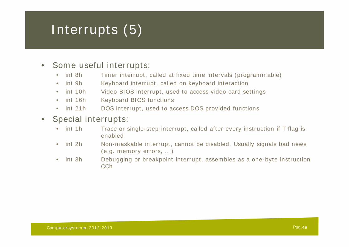
• Some useful interrupts:• int 8h Timer interrupt, called at fixed time intervals (programmable)• int 9h Keyboard interrupt, called on keyboard interaction• int 10h Video BIOS interrupt, used to access video card settings• int 16h Keyboard BIOS functions• int 21h DOS interrupt, used to access DOS provided functions
• Special interrupts:• int 1h Trace or single-step interrupt, called after every instruction if T flag is
enabled• int 2h Non-maskable interrupt, cannot be disabled. Usually signals bad news
(e.g. memory errors, ...)• int 3h Debugging or breakpoint interrupt, assembles as a one-byte instruction
CCh
Computersystemen 2012-2013 49
Pag.
I/O Ports
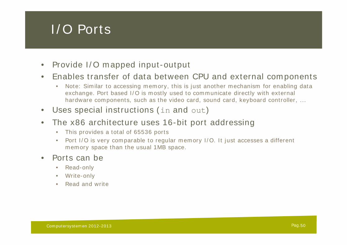
• Provide I/O mapped input-output• Enables transfer of data between CPU and external components
• Note: Similar to accessing memory, this is just another mechanism for enabling data exchange. Port based I/O is mostly used to communicate directly with external hardware components, such as the video card, sound card, keyboard controller, ...
• Uses special instructions (in and out)• The x86 architecture uses 16-bit port addressing
• This provides a total of 65536 ports• Port I/O is very comparable to regular memory I/O. It just accesses a different
memory space than the usual 1MB space.
• Ports can be• Read-only• Write-only• Read and write
Computersystemen 2012-2013 50
Pag.
Hello World!
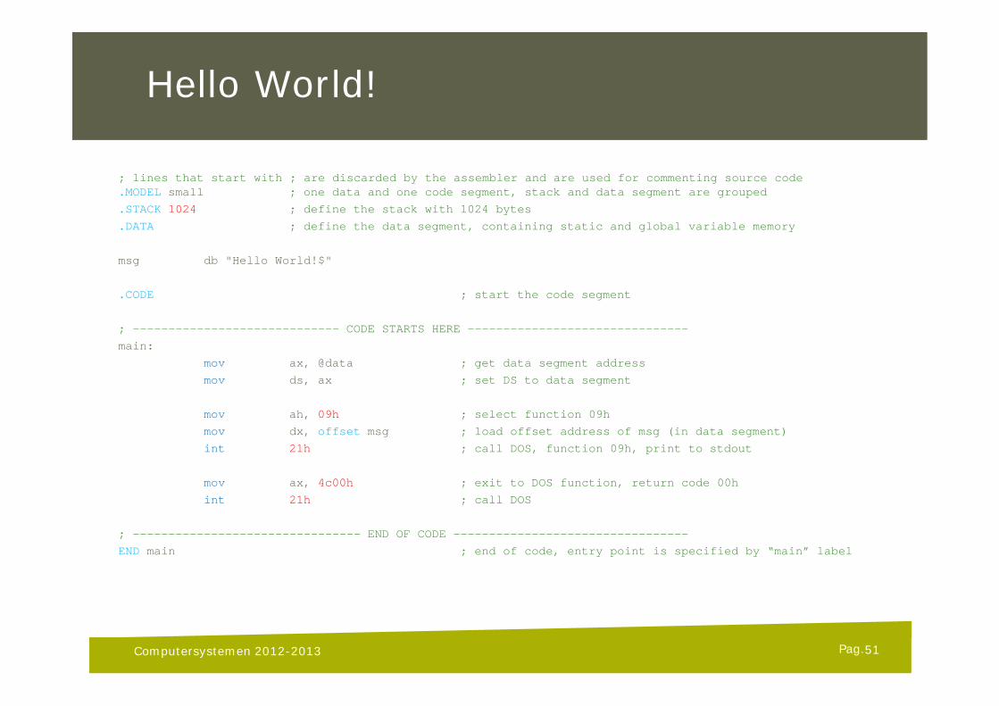
; lines that start with ; are discarded by the assembler and are used for commenting source code.MODEL small ; one data and one code segment, stack and data segment are grouped
.STACK 1024 ; define the stack with 1024 bytes
.DATA ; define the data segment, containing static and global variable memory
msg db "Hello World!$"
.CODE ; start the code segment
; ----------------------------- CODE STARTS HERE -------------------------------
main:
mov ax, @data ; get data segment address
mov ds, ax ; set DS to data segment
mov ah, 09h ; select function 09h
mov dx, offset msg ; load offset address of msg (in data segment)
int 21h ; call DOS, function 09h, print to stdout
mov ax, 4c00h ; exit to DOS function, return code 00h
int 21h ; call DOS
; -------------------------------- END OF CODE ---------------------------------
END main ; end of code, entry point is specified by “main” label
Computersystemen 2012-2013 51
Pag.
Loop Examples
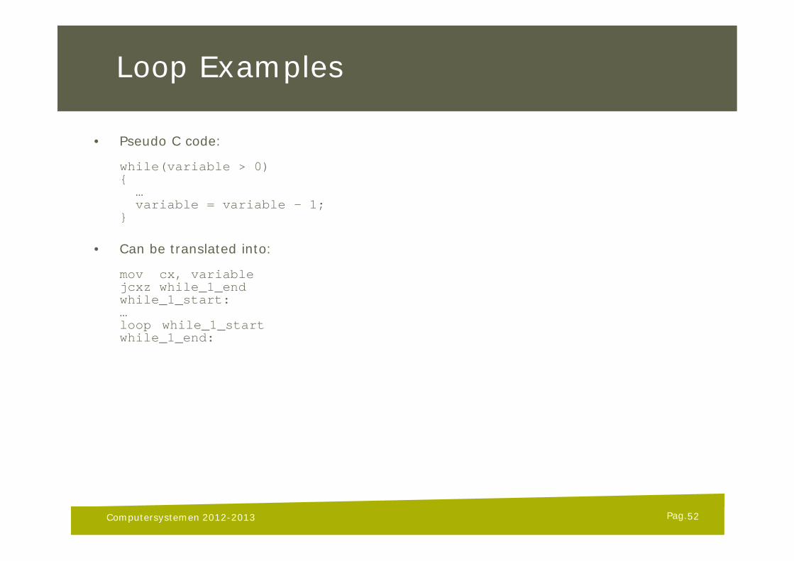
• Pseudo C code:
while(variable > 0){
…variable = variable - 1;
}
• Can be translated into:
mov cx, variablejcxz while_1_endwhile_1_start:…loop while_1_startwhile_1_end:
Computersystemen 2012-2013 52
Pag.
Simple Key Examples
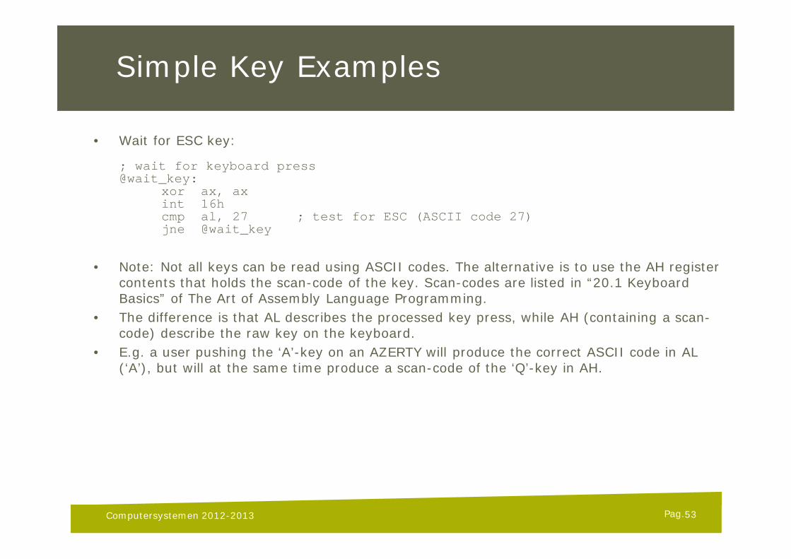
• Wait for ESC key:
; wait for keyboard press@wait_key:
xor ax, axint 16hcmp al, 27 ; test for ESC (ASCII code 27)jne @wait_key
• Note: Not all keys can be read using ASCII codes. The alternative is to use the AH register contents that holds the scan-code of the key. Scan-codes are listed in “20.1 Keyboard Basics” of The Art of Assembly Language Programming.
• The difference is that AL describes the processed key press, while AH (containing a scan-code) describe the raw key on the keyboard.
• E.g. a user pushing the ‘A’-key on an AZERTY will produce the correct ASCII code in AL (‘A’), but will at the same time produce a scan-code of the ‘Q’-key in AH.
Computersystemen 2012-2013 53
Pag.
Screen Examples
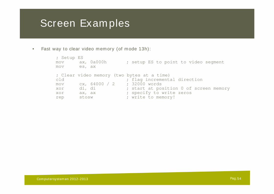
• Fast way to clear video memory (of mode 13h):
; Setup ESmov ax, 0a000h ; setup ES to point to video segmentmov es, ax
; Clear video memory (two bytes at a time)cld ; flag incremental directionmov cx, 64000 / 2 ; 32000 wordsxor di, di ; start at position 0 of screen memoryxor ax, ax ; specify to write zerosrep stosw ; write to memory!
Computersystemen 2012-2013 54
Pag.
Screen Examples
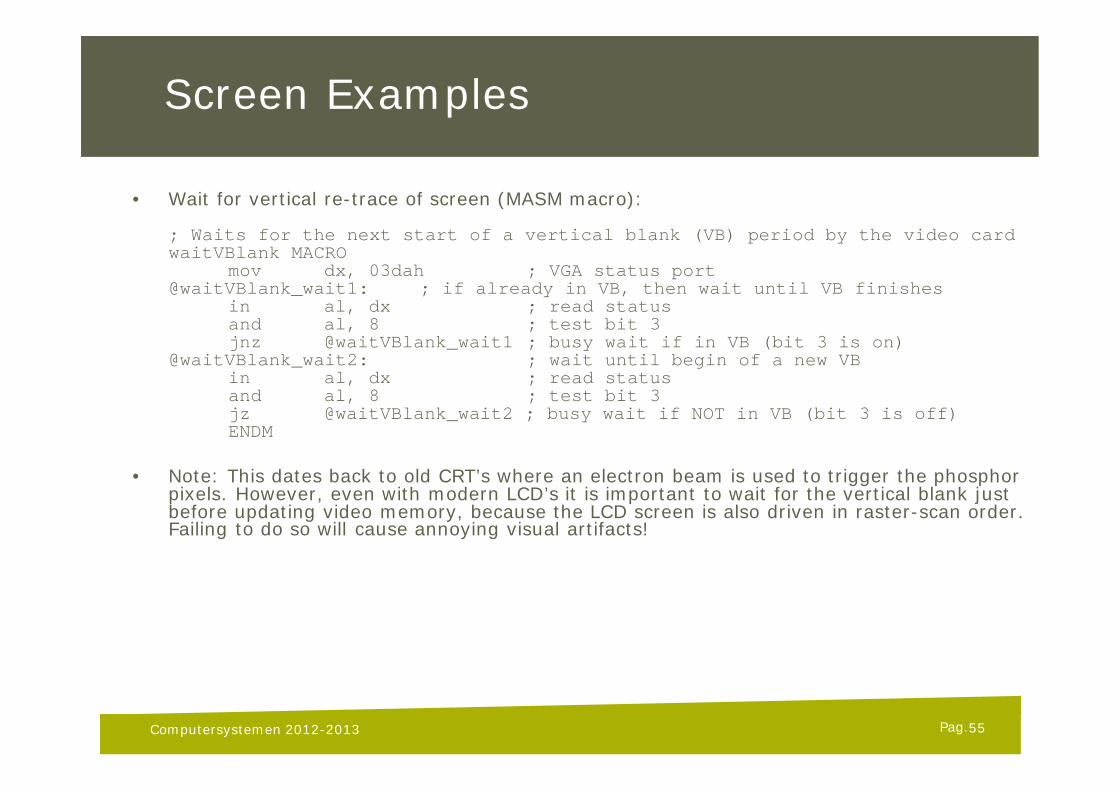
• Wait for vertical re-trace of screen (MASM macro):
; Waits for the next start of a vertical blank (VB) period by the video cardwaitVBlank MACRO
mov dx, 03dah ; VGA status port@waitVBlank_wait1: ; if already in VB, then wait until VB finishes
in al, dx ; read statusand al, 8 ; test bit 3jnz @waitVBlank_wait1 ; busy wait if in VB (bit 3 is on)
@waitVBlank_wait2: ; wait until begin of a new VBin al, dx ; read statusand al, 8 ; test bit 3jz @waitVBlank_wait2 ; busy wait if NOT in VB (bit 3 is off)ENDM
• Note: This dates back to old CRT’s where an electron beam is used to trigger the phosphor pixels. However, even with modern LCD’s it is important to wait for the vertical blank just before updating video memory, because the LCD screen is also driven in raster-scan order. Failing to do so will cause annoying visual artifacts!
Computersystemen 2012-2013 55
Pag.
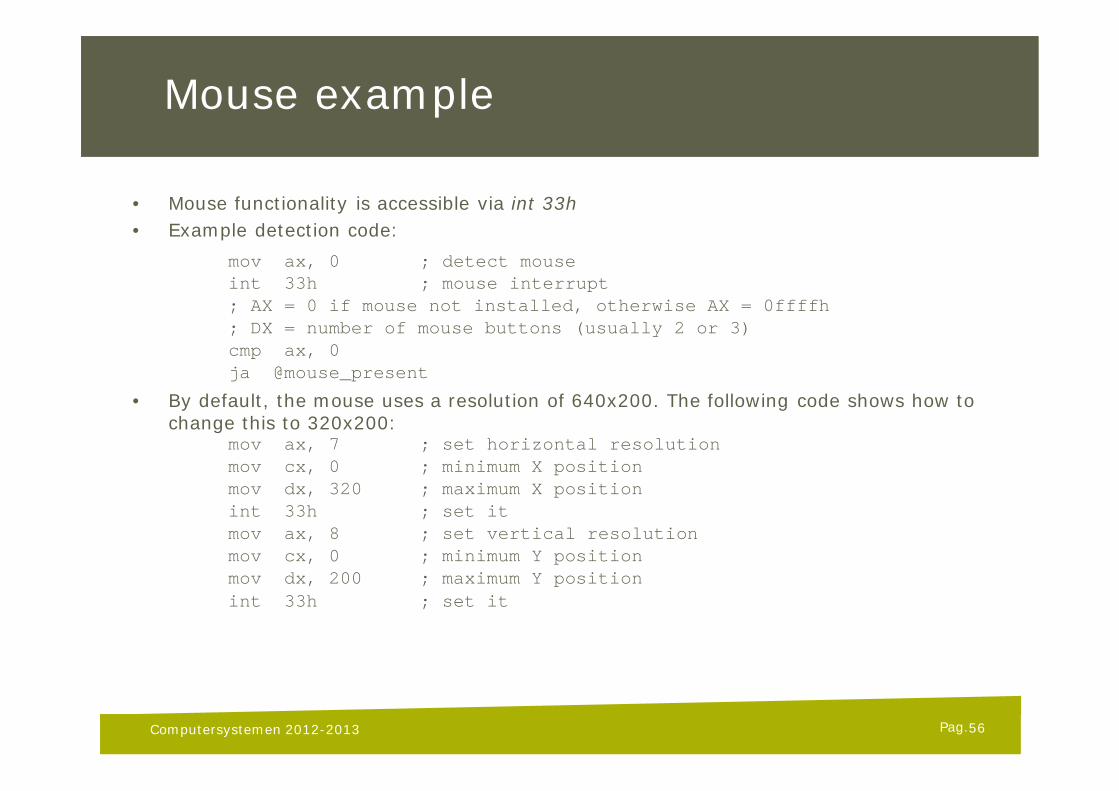
Mouse example
• Mouse functionality is accessible via int 33h• Example detection code:
mov ax, 0 ; detect mouseint 33h ; mouse interrupt; AX = 0 if mouse not installed, otherwise AX = 0ffffh; DX = number of mouse buttons (usually 2 or 3)cmp ax, 0ja @mouse_present
• By default, the mouse uses a resolution of 640x200. The following code shows how to change this to 320x200:
mov ax, 7 ; set horizontal resolutionmov cx, 0 ; minimum X positionmov dx, 320 ; maximum X positionint 33h ; set itmov ax, 8 ; set vertical resolutionmov cx, 0 ; minimum Y positionmov dx, 200 ; maximum Y positionint 33h ; set it
Computersystemen 2012-2013 56
Pag.
Mouse example
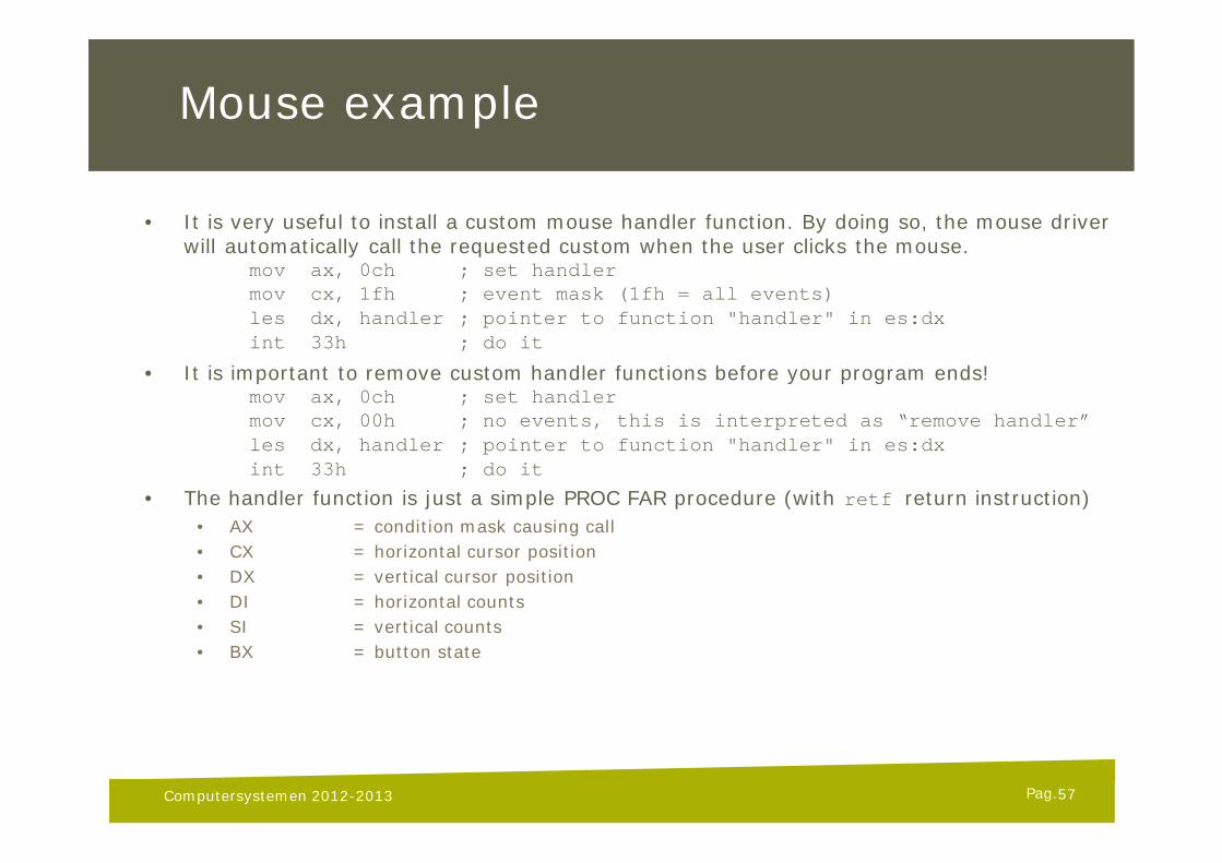
• It is very useful to install a custom mouse handler function. By doing so, the mouse driver will automatically call the requested custom when the user clicks the mouse.
mov ax, 0ch ; set handlermov cx, 1fh ; event mask (1fh = all events)les dx, handler ; pointer to function "handler" in es:dxint 33h ; do it
• It is important to remove custom handler functions before your program ends!mov ax, 0ch ; set handlermov cx, 00h ; no events, this is interpreted as “remove handler”les dx, handler ; pointer to function "handler" in es:dxint 33h ; do it
• The handler function is just a simple PROC FAR procedure (with retf return instruction)• AX = condition mask causing call• CX = horizontal cursor position• DX = vertical cursor position• DI = horizontal counts• SI = vertical counts• BX = button state
Computersystemen 2012-2013 57
Pag.
References
1. The Art of Assembly Language Programminghttp://webster.cs.ucr.edu/www.artofasm.com/DOS/index.html (Use this e-book! It’s free…)
2. Microsoft MASM 6.1 Reference Guide
Computersystemen 2012-2013 58