inteliatsnt - ipd industrial products product attachments/isolators and... · the configuration to...
TRANSCRIPT

June 2010 Copyright © 2010 ComAp s.r.o. Written by Vlastimil Vostřák Prague, Czech Republic
ComAp, spol. s r.o. Kundratka 2359/17, 180 00 Praha 8, Czech Republic Tel: +420 246 012 111, Fax: +420 266 316 647 E-mail: [email protected], www.comap.cz
Reference Guide
®
Automatic Transfer Switch Controller
SW version 2.0, June 2010
InteliATSNT
IA-NT STD unit

InteliATSNT STD, SW version 2.0, ©ComAp – June 2010 2 IA-NT- STD-2.0-Reference Guide.pdf
ts ..................... 2 ..................... 4 ..................... 4
4 ..................... 4 ..................... 5 ..................... 5 ..................... 7 ..................... 7 ................... 10 ................... 10 ................... 11 ................... 14 ................... 14 ................... 15 ................... 15 ................... 18 ................... 18 ................... 19 ................... 20 ................... 20 ................... 21 ................... 22 ................... 23 ................... 23 ................... 24 ................... 25 ................... 26 ................... 27 ................... 28 ................... 30 ................... 30 ................... 33 ................... 33 ................... 35 ................... 35 ................... 36 ................... 37 ................... 37 ................... 39 ................... 39 ................... 39 ................... 41 ................... 43 ................... 43 ................... 45
Alarm Management ............................................................................................................................... 46 Warning (WRN)................................................................................................................................. 46 Trip ( .......................................................................................................................................... 46 Mains failure (MF) ............................................................................................................................. 46 AMF time chart – genset OK............................................................................................................. 47 AMF time chart – genset not started properly................................................................................... 47 Voltage phase sequence detection................................................................................................... 48
Gen-set Operation States...................................................................................................................... 49 List of possible events....................................................................................................................... 49
Table of ContenTable of Contents ...............................................................................................................Document information ........................................................................................................
Clarification of notation...................................................................................................Text .....................................................................................................................................................Conformity Declaration...................................................................................................
General Guidelines.............................................................................................................What is in this manual? ..................................................................................................
Description..........................................................................................................................Description of the controller system...............................................................................Configurability.................................................................................................................
. .What is in the package?..... .................................................................................... ......IL-NT RS232 Communication module ...........................................................................IL-NT RS232-485 Communication module ....................................................................IL-NT S-USB Service USB communication module.......................................................IL-NT RD Remote display software ...............................................................................IB-Lite Communication module......................................................................................IL-NT BIO8 Hybrid binary input/output module ..............................................................Programming of IA-NT controller ...................................................................................
User Interface .....................................................................................................................Terminals............................................................................................................................
IA-NT STD terminals and face .......................................................................................Recommended Wiring ........................................................................................................
.IA-NT STD – Wiring Diagram.................................................................................. ......Applications ........................................................................................................................
AMF using two separate breakers (MCB and GCB) ......................................................AMF using two-position ATS..........................................................................................
TRP)
AMF using three-position ATS .......................................................................................AMF + manual transfer & neutral control using three-position ATS ..............................
.AMF + no battery operation .................................................................................... ......Controllers in cascade....................................................................................................
Getting Started ...................................................................................................................How to install ..................................................................................................................Three phase applications ...............................................................................................Single phase applications ..............................................................................................
Inputs and Outputs .............................................................................................................Binary inputs IA-NT - default ..........................................................................................Binary inputs – list ..........................................................................................................Binary outputs IA-NT - default........................................................................................Binary outputs - list.........................................................................................................
Setpoints.............................................................................................................................Password..... ..................................................................................................................
..
Basic Settings.......................................................................................................... ......AMF Settings..................................................................................................................
Function Description...........................................................................................................Operating modes............................................................................................................Circuit breakers timing ...................................................................................................
InteliATSNT STD, SW version 2.0, ©ComAp – June 2010 3 IA-NT- STD-2.0-Reference Guide.pdf
................... 50
................... 50
................... 50
................... 51
................... 51
................... 51
................... 51
................... 51
................... 52
................... 52
................... 52
................... 52
................... 53
................... 55
................... 55
................... 56
................... 56
................... 56
................... 56
................... 56
................... 57
................... 57
................... 57 IL-NT RS232-485 interface (optional card) ....................................................................................... 57 IL-NT S-USB interface (optional card) .............................................................................................. 58 IB-Lite interface (optional card) ......................................................................................................... 58 IL-NT BIO8 extension module (optional card)................................................................................... 58
Remote Control and Data Logging.....................................................................................Direct connection to the PC ...........................................................................................PC software – LiteEdit....................................................................................................
.Remote Communication.............................................................................................. ......Internet connection.........................................................................................................Recommended ISDN modem ........................................................................................Recommended GSM modem.........................................................................................Mobile SIM card setting..................................................................................................
IL-NT-RD Remote display software....................................................................................General description ........................................................................................................Warning ! ........................................................................................................................IL-NT-RD Software installation.......................................................................................IL-NT-RD Wiring.............................................................................................................Function description .......................................................................................................SW compatibility.............................................................................................................
Technical Data....................................................................................................................Inputs/Outputs overview.................................................................................................Power supply..................................................................................................................Operating conditions ......................................................................................................Dimensions and weight ..................................................................................................Mains and generator ......................................................................................................Binary inputs and outputs...............................................................................................IL-NT RS232 interface (optional card) ...........................................................................
InteliATSNT STD, SW version 2.0, ©ComAp – June 2010 4 IA-NT- STD-2.0-Reference Guide.pdf
ion EFERENCE GUIDE
12111, FAX: +420266316647 .COMAP.CZ
Document informatINTELIATSNT STD® - RWRITTEN BY: VLASTIMIL VOSTŘÁK ©2009-2010 COMAP LTD. KUNDRATKA 17, PRAHA 8, CZECH REPUBLIC PHONE: +4202460WEB: HTTP://WWW , -MAIL: IN [email protected]
DOCUMENT HISTORY
E F
REVISION NUMBER RELATED SW. VERSION DATE
1 1.0 22.02.2009
2 1.0.1 24.03.2009
3 1.2 09.01.2010
4 2.0 09.06.2010
Clarification of notation NOTE: This type of paragraph calls readers attention to a notice or related theme. CAUTION! This type of paragraph highlights a procedure, adjustment etc., which can cause a damage or unproper function of the equipment if not performed correctly and may not be clear at first sight. WARNING! This type of paragraph indicates things, procedures, adjustments etc. which need high level of attent th ause personal injury or death. ion, o erwise can c
Text
PAGE (Capital letters in the frame) buttons on the front panel Break RGeneraREMO
Conformity Declaration
eturn (Italic) set points tor protections (Bold) Set point group
TE START/STOP (Capital letters) binary inputs and outputs
The following described machine complies with the appropriate basic safety and health requirement of the EC Low Voltage Directive No: 73/23 / EEC and EC Electromagn tic Compatib i tive 89/336 / EEC based on its design and type, as brought into circulation by us.
e ility D rec
InteliATSNT STD, SW version 2.0, ©ComAp – June 2010 5 IA-NT- STD-2.0-Reference Guide.pdf
es General Guidelin
What is in this manual? This manual describes the InteliATSNT STD (IA-NT-STD) software, which is designed for automatic
s and provides general information on how to install and operate the
• Automatic transfer switch panel builders otely from InteliATSNT)
d maintenance of the gen-set
NT ns of the NT-STD-HW_1.3-.AIL) form the
higher too, which is ATSNT SW must be
rature ATS controller.
transfer switch applicationIn li NTte ATS controller. This manual is dedicated for
• Operators of remote gen-sets (started rem• For everybody who is concerned with installation, operation an
InteliATS controller SW and HW versions compatibility Software InteliATSNT is compatible with the InteliATSNT hardware v. 1.3 and higher. There are two modifications of the InteliATS HW - STD and PWR and two modificatioInteliATSNT SW – STD and PWR which together with the appropriate archive file (IA-X.X.AIL for STD HW 1.3, IA-NT-STD-X.X.AIL for STD HW > 1.3 and IA-NT-PWR-X.XInteliATSNT PWR or STD controller. Beside that the InteliATSNT software is compatible with IL-NT AMF HW 1.3 andused when a low temperature ATS application is needed. In this case the Intelicombined (purchased) with the IL-NT AMF 25 LT HW to obtain the low tempe NOTE: Because of large variety of InteliATSNT parameters settings, it is not possible to describe any combination. Some of InteliATSNT functions are subject of changes depend on SW version. The data in this manual only describes the product and are not warranty of performance or characteristic. CAUTION! SW and HW must be compatible (e.g. IA-NT firmware and IA-NT HW) otherwise the function will be disabled. If wrong software is downloaded, message HARDWARE INCOMPATIBLE appears on controller screen. In this case use Boot load (jumper) programming – close Boot jumper and follow instructions in LiteEdit, download correct software. NOTE: C rmation provided herein is correct and reliable and reserves the right to omAp believes that all infou omAp does not assume any responsibility for its use unless otherwise expressly pdate at any time. Cundertaken. WARNING! Remote control - InteliATSNT controller can be remotely controlled. In case of the work on the controlled devices check, that nobody can perform remote operation.To be sure disconnect - remote control via RS232 line - input REM TRANSFER - input REMOTE AUT - input REMOTE TEST or disconnect output Rem START/ST utputs GCB CLOSE/OPEN and MCB CLOSE/OPEN
OP and o
InteliATSNT STD, SW version 2.0, ©ComAp – June 2010 6 IA-NT- STD-2.0-Reference Guide.pdf
WARNING! E wing InteliATSNT controller terminals: very time you want to disconnect follo - Mains voltage measuring and / or - Binary output for MCB control and / or Switch InteliATSNT to MAN or OFF Mode or disconnect the Binary outputs Rem Start/Stop and GCB Close/Open to avoid unexpected automatic start of gen-set and GCB closing. WARNING!
Dangerous voltage In no case touch the terminals for voltage and measurement!
Always connect grounding terminals!
The following instructions are for qualified personnel only. To avoid personal injury do not perform any action not specified in this Reference guide!!!

InteliATSNT STD, SW version 2.0, ©ComAp – June 2010 7 IA-NT- STD-2.0-Reference Guide.pdf
n Descriptio
Description of the controller system InteliATSNT is a comprehensive Automatic Transfer Switch controller designed to monAC mains supply (1 or 3 phases) for under & over voltage, under & over frequency anunbalance. In the case of any mains supply disproportion it will send a remote start cogen-set and make change over for both
itor the incoming d voltage mmand to the
generator and mains contactors. The gen-set requires a ast a key-start box
over Controllers
ad transfer between both power sources with break (blackout). Delayed Transition means
used as a switching
r MAINS-GEN he system recognizes application type according to the Gen Start/Stop and Gen
d (default ured, MAINS-
n type takes place. In this case stop-fail protection and generator current protection
ay showing icons, symbols and bar-ionality, new standards in Gen-set
• Easy-to-use operation and installation. Factory default configuration covers most of applications
• Different customer changes are possible thanks to the configurability • Excellent remote communication capabilities • High reliability
remote start type control unit (e.g. the ComAp InteliLiteNT MRS 10 controller), at lewith an external input for the start/stop signal.
The controller uses Open Delayed Transition. This transition is a standard type of changeprovided by the most common AMF or ATS controllers supplied by the other vendors. perform lothere is a delay between the source breaker opening and the target breaker closing. Two or three position ATS switch or two independent breakers/contactors can bemechanism.
InteliATSNT controller can be used also for MAINS-MAINS applications and not only foapplications. TReadyToLoad logical binary output and input configuration. If both are configured/usesetting) it tells controller that MAINS-GEN application type is to be used. If not configMAINS applicatioa nre ot evaluated.
n eliATSNTI t controllers are equipped with a powerful graphic displgraphs for intuitive operation, which sets, together with high functcontrols. The key features are:

InteliATSNT STD, SW version 2.0, ©ComAp – June 2010 8 IA-NT- STD-2.0-Reference Guide.pdf
Open Delay Transition functional diagram..
H :INT transition can perform fastest possible changeover if Transfer Del is set to zero value.This
Overall blackout time then equals to 20 ms + breaker reaction time. HINT: Use longer delay time to avoid problems with motor starters. (Motor starts prefer to see break of a few seconds so they can initialize properly). HINT: To avoid issues with contactor mechanical interlocks use delay 0.75s or longer (mech. interlock on contactors takes some time to clear). If you try to close one contactor before interlock has cleared it can jam and you end up with out supply to load).

InteliATSNT STD, SW version 2.0, ©ComAp – June 2010 9 IA-NT- STD-2.0-Reference Guide.pdf
Example application
InteliATSNT STD, SW version 2.0, ©ComAp – June 2010 10 IA-NT- STD-2.0-Reference Guide.pdf
Configurability One of the key features of the controller is high level of adaptability of the system to the needs of
y particular application. The way, how to achieve this, is the configuration. ever
NOTE: Use LiteEdit PC software to read configuration from the controller or disk, view it, modify it and write the configuration to controller or disk. The firmware contains a number of binary inputs and outputs needed for all necessaryavailable in the
functions firmware. But not all functions are required at the same time on different gen-sets and
also the controller hardware does not have so many input and output terminals. One of the main tasks ion is mapping of "logical" firmware inputs and outputs to the "physical" hardware
i
C
1. Mapping of logical binary inputs (functions)
of the configuratnputs and outputs.
onfiguration parts:
or assigning alarms to physical binary input terminals
2. Mapping of logical binary outputs (functions) to physical binary output termin3. Changing language
als of the controller texts
tandart eEdit software. See
tion for details.
The controller is delivered with a default configuration, which should fit to most sapplications. This default configuration can be changed only using PC and LitLiteEdit documenta
NOTE: You need one of communication modules to connect the controller to a PC with LiteEdit. There is a special easy removable service module for cases, where there is no communication module permanently attached.
ther controller or is called archive and has file extension ".ail". An archive contains full
image of the controller at the moment of saving (if the controller is online to the PC) except firmware, are also current adjustment of all setpoints, all measured values, a
ist.
ers aring controllers with configu
in
Once the configuration is modified, it can be stored in a file for later usage with anofor backup purposes. The file
i.e. besides configuration therecopy of history log and a copy of alarm l
Tidentical
he archive can be simply use cloning of controllration and settings.
d for , which means prep
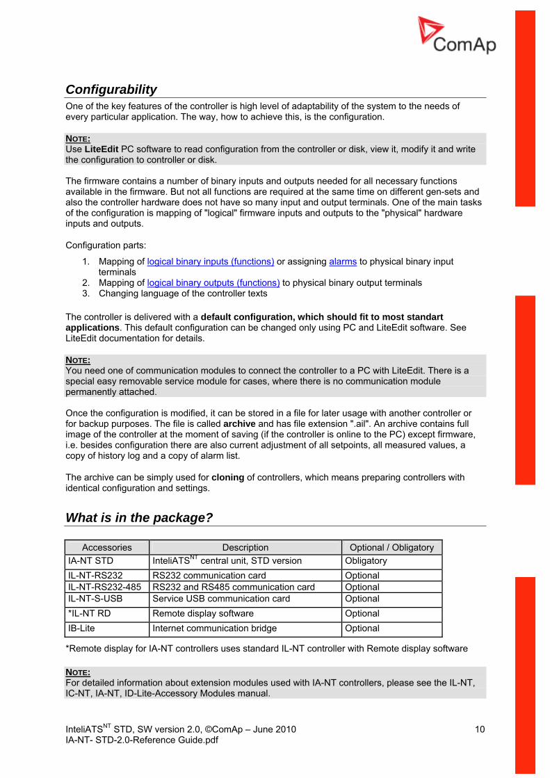
What is the package?
Accessories Description Optional / Obligatory IA-NT STD InteliATSNT central unit, STD version Obligatory IL-NT-RS232 RS232 communication card Optional IL-NT-RS232-485 RS232 and RS485 communication card Optional IL-NT-S-USB Service USB communication card Optional *IL-NT RD Remote display software Optional IB-Lite Internet commu o ridge Optional nicati n b
*Remote display for IA-NT controllers uses standard IL-NT controller with Remote display software
NOTE: For detailed information about extension modules used with IA-NT controllers, please see the IL-NT, IC-NT, IA-NT, ID-Lite-Accessory Modules manual.
InteliATSNT STD, SW version 2.0, ©ComAp – June 2010 11 IA-NT- STD-2.0-Reference Guide.pdf
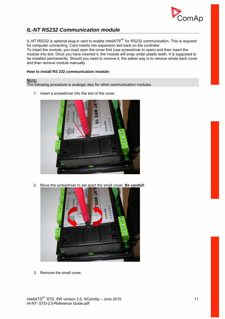
IL-NT RS232 Communication module
NTIL-NT RS232 is optional plug-in card to enable InteliATS for RS232 communication. This is required for computer connecting. Card inserts into expansion slot back on the controller. To insert the module, you must open the cover first (use screwdriver to open) and thenmodule into slot. Once you ha
insert the ve inserted it, the module will snap under plastic teeth. It is supposed to
be installed permanently. Should you need to remove it, the safest way is to remove whole back cover
and than remove module manually. How to install RS 232 communication module:
NOTE: The following procedure is analogic also for other communication modules.
1. Insert a screwdriver into the slot of the cover.
2. Move the screwdriver to set apart the small cover. Be careful!
3. Remove the small cover.
InteliATSNT STD, SW version 2.0, ©ComAp – June 2010 12 IA-NT- STD-2.0-Reference Guide.pdf
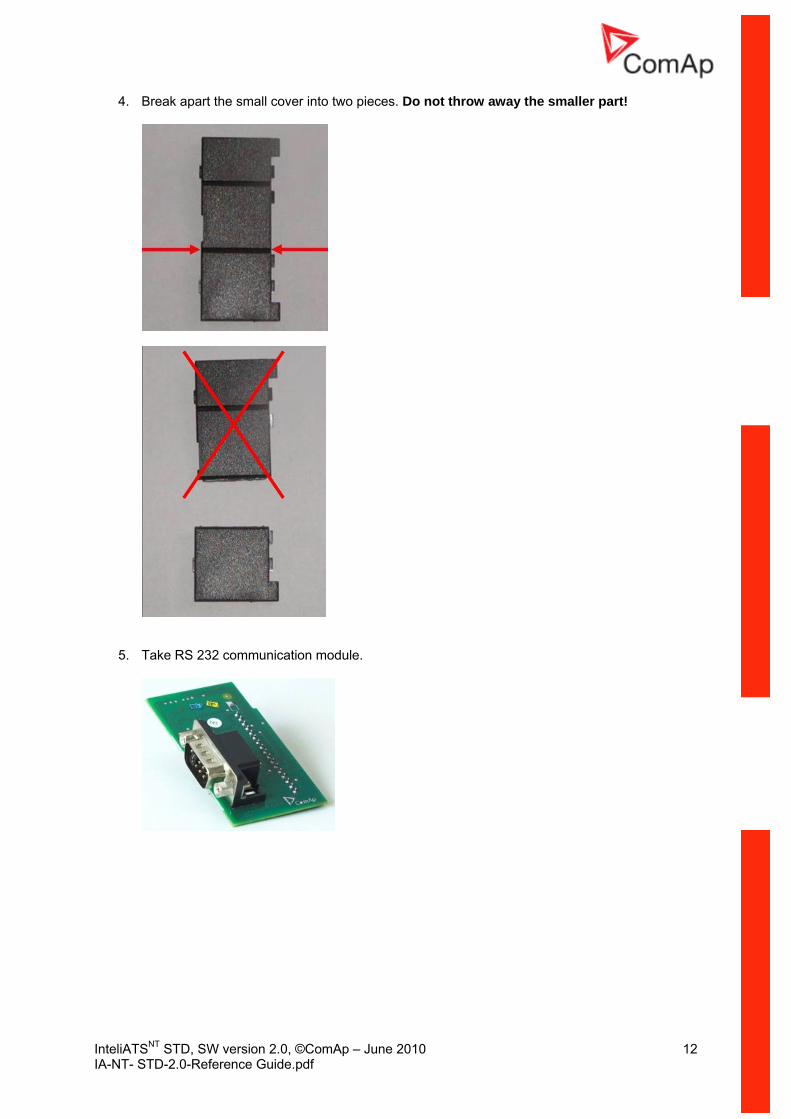
4. Break apart the small cover into two pieces. Do not throw away the smaller part!
5. Take RS 232 communication module.

InteliATSNT STD, SW version 2.0, ©ComAp – June 2010 13 IA-NT- STD-2.0-Reference Guide.pdf
unication module into the slot of the controller. 7. Put back the small cover.
6. Plug RS 232 comm
NOTE: When you insert RS 232 communication module, the boot jumper is hidden. For that reason we recommend to use RS 232 communication module with the boot jumper placed on it. See pictures below:
RS 232 communication module with the boot jumper.
InteliATSNT STD, SW version 2.0, ©ComAp – June 2010 14 IA-NT- STD-2.0-Reference Guide.pdf
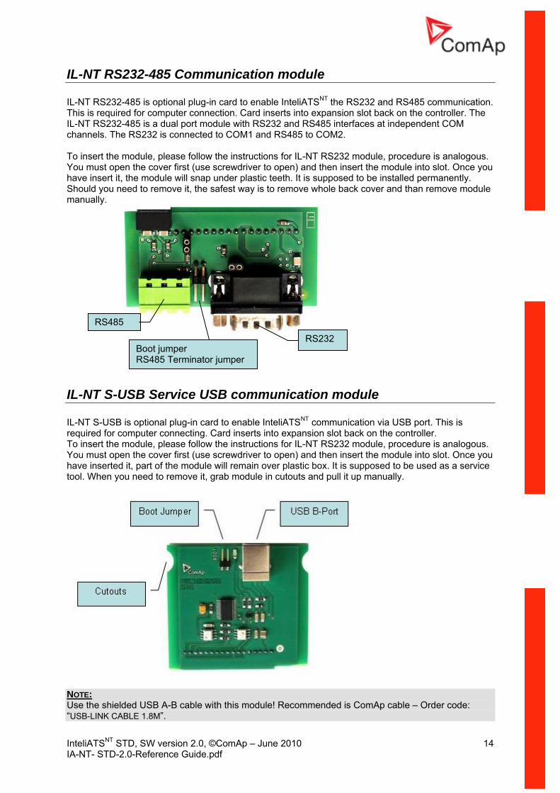
IL-NT RS232-485 Communication module IL-NT RS232-485 is optional plug-in card to enable InteliATSNT the RS232 and RS485This is required for computer connection. Card inserts into expansion slot back on the coIL-NT RS232-485 is a dual port module with RS232 and RS48
communication. ntroller. The
5 interfaces at independent COM
s analogous. slot. Once you
will snap under plastic teeth. It is supposed to be installed permanently. Should you need to remove it, the safest way is to remove whole back cover and than remove module manually.
channels. The RS232 is connected to COM1 and RS485 to COM2. To insert the module, please follow the instructions for IL-NT RS232 module, procedure iYou must open the cover first (use screwdriver to open) and then insert the module intohave insert it, the module
RS485
RS232 Boot jumper RS485 Terminator jumper
IL-NT S-USB Service USB communication module
NTIL-NT S-USB is optional plug-in card to enable InteliATS communication via USB port. This is required for computer connecting. Card inserts into expansion slot back on the controller. To insert the module, please follow the instructions for IL-NT RS232 module, procedure is analogous. You must open the cover first (use screwdriver to open) and then insert the module into slot. Once you have inserted it, part of the module will remain over plastic box. It is supposed to be used as a service tool. When you need to remove it, grab module in cutouts and pull it up manually.
NOTE: Use the shielded USB A-B cable with this module! Recommended is ComAp cable – Order code: “USB-LINK CABLE 1.8M”.
InteliATSNT STD, SW version 2.0, ©ComAp – June 2010 15 IA-NT- STD-2.0-Reference Guide.pdf
IL-NT RD Remote display software IL-NT RD is remote display software for a controller. Remote display provides the sammonitoring functions as controller itself. Remote display for IA-NT controllers uses stacontroller with IL-NT Remote display software. No further programing of the display is is self configurable from the main controller. It is connected with the c
e control and ndard IA-NT required – unit
ontroller via IL-NT-RS232 communication modules using RS232 line. Longer distances (up to 1200m) are possible using IL-NT-
2/RS485 converters are used. RS232-485 communication module or when RS23 The IL-NT RD hardware type should fit to the master IA-NT. NOTE: Please see the “IL-NT-RD Remote display software” chapter for more details.
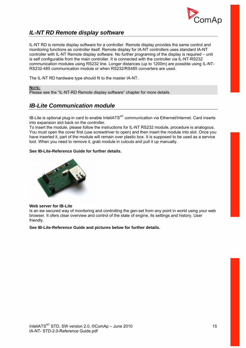
module IB-Lite Communication IB-Lite is optional plug-in card to enable InteliATSNT communication via Ethernet/Interninto expansion slot back on the controller.
et. Card inserts
ctions for IL-NT RS232 module, procedure is analogous. river to open) and then insert the module into slot. Once you
have inserted it, part of the module will remain over plastic box. It is supposed to be used as a service tool. When you need to remove it, grab module in cutouts and pull it up manually. See IB-Lite-Reference Guide for further details.
To insert the module, please follow the instruYou must open the cover first (use screwd
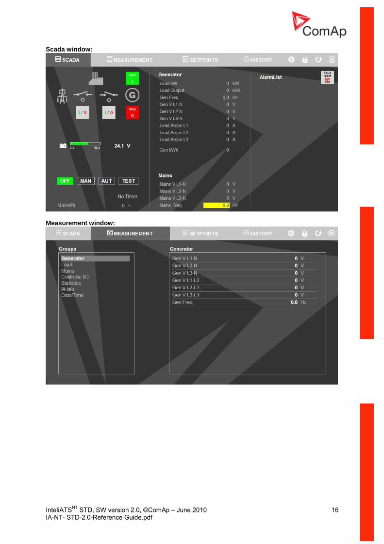
Web server for IB-Lite Is an ew secured way of monitoring and controlling the gen-set from any point in world using your web browser. It ofers clear overview and control of the state of engine, its settings and history. User friendly.
See IB-Lite-Reference Guide and pictures below for further details.
InteliATSNT STD, SW version 2.0, ©ComAp – June 2010 16 IA-NT- STD-2.0-Reference Guide.pdf
Scada window:
Measurement window:

InteliATSNT STD, SW version 2.0, ©ComAp – June 2010 17 IA-NT- STD-2.0-Reference Guide.pdf
Setpoints window:
History window:
HINT: This feature requires IB-Lite optional plug-in module and visible connection of controller to Ethernet.

InteliATSNT STD, SW version 2.0, ©ComAp – June 2010 18 IA-NT- STD-2.0-Reference Guide.pdf
e up to 8 binary sily
Installing IL-NT BIO8 module is similar to installing RS 232 module. The difference is that module fits to “Extension module” slot and after installing IL-NT BIO8 you do not put back the small cover.
IL-NT BIO8 Hybrid binary input/output module
IL-NT BIO8 is optional plug-in card. Through this card controller can accommodatinputs or outputs. In LiteEdit PC configuration tool (version 4.4 and higher) it is possible to eachoose if particular I/O will be binary input or output.
Programming of IA-NT controller
ning. Programming is possible only in MAN mode when the engine is not run NOTE: For more information on programing, see LiteEdit Reference Guide. CAUTION! Check the statistic values after firmware upgrade. Readjust the values if necessary.
InteliATSNT STD, SW version 2.0, ©ComAp – June 2010 19 IA-NT- STD-2.0-Reference Guide.pdf
e s of displaying
only monitor
sire to change the
Changing the mode of User Interface is possible from default measuring screen of controller by an press again PAGE. On screen will be
displeyed the choice of two different User Interfaces. Please see latest IA-NT Operators Guide for detailed description.
User InterfacThere is an interchangable User Interface on controller. It allows two different modecontroller menu. The first mode called USER is dedicated for users who prefer easy function and needactual values, see alarms or change language settings. Second mode is called ENGINEER and it is dedicated for advaced users, who desettings of controller, monitor all values and check the history of events.
simultaneous pressing the ENTER and PAGE button and th

InteliATSNT STD, SW version 2.0, ©ComAp – June 2010 20 IA-NT- STD-2.0-Reference Guide.pdf
s
IA-NT STD terminals and face
Terminal

InteliATSNT STD, SW version 2.0, ©ComAp – June 2010 21 IA-NT- STD-2.0-Reference Guide.pdf
Installation
Mounting The controller is to be mounted onto the switchboard door. Requested cutout size is 175x115mm. Use the screw holders delivered with the controller to fix the controller into the door as described on pictures below.

InteliATSNT STD, SW version 2.0, ©ComAp – June 2010 22 IA-NT- STD-2.0-Reference Guide.pdf
ing
IA-NT STD – Wiring Diagram
Recommended WirL1 L2 L3 N
DIES
EL/G
ASEN
GINE
GENE
RATO
R
G
RS-
232C
Inte
rfac
e
Mode
mor
PC
IIREM TRANSFER
MAINS FAIL BLOCKREMOTE AUT
GCB CLOSE/OPEN
GEN START/STOP
NEUTRAL POS
MCB CLOSE/OPEN
CONTROLSIGNALS
BATTERY
-++24V
0V
BINARYOUTPUTS
0
I
ATS
SW
ITC
H
GEN-SET CONTROLLER
LOA
D

InteliATSNT STD, SW version 2.0, ©ComAp – June 2010 23 IA-NT- STD-2.0-Reference Guide.pdf
s plication, where the
s for the mains power supply fault and then starts a load transfer process. Next possible application is manually controlled load transfer between two power supply sources
AMF using two separate breakers (MCB and GCB)
ApplicationThe most typical application for the ATS controllers is Auto Mains Failure (AMF) apcontroller watche
(mains x generator).
G
IA-NT
GCB3x
LOAD
3xU
M
3xU
G
MCB3x
T 3x
K4
MCB GCB
3x
MCB CLOSE/OPEN
GCB CLOSE/OPEN BO
MCB
K3
GCB
Specification • Automatic remote gen-set start when the mains fails (AUT mode)
control • Break transfer on mains failure • Break return on mains return (Load reclosing) • Test mode (set running and waiting for mains failure)
Hardware requirements 1x IA-NT STD
• GCB & MCB

InteliATSNT STD, SW version 2.0, ©ComAp – June 2010 24 IA-NT- STD-2.0-Reference Guide.pdf
AMF using two-position ATS
G
IA-NT
3x
3xU
M
3xU
G
3x
T
3x
GCB CLOSE/OPENBO
K3
LOAD
ATS
3x
ATS
I II
Specification • -set start when the mains fails (AUT mode)
fer on mains failure • Break return on mains return (Load reclosing) • Test mode (set running and waiting for mains failure)
Hardware requirements 1x IA-NT STD
Automatic remote gen• Two-position ATS • Break trans

InteliATSNT STD, SW version 2.0, ©ComAp – June 2010 25 IA-NT- STD-2.0-Reference Guide.pdf
AMF using three-position ATS
G
IA-NT
3x
3xU
M
3xU
G
3x
T
3x
MCB CLOSE/OPEN
GCB CLOSE/OPEN
BO
LOAD
ATS
3x
ATS
I II0
K4K3
Specification • Automatic remote gen-set start when the mains fails (AUT mode)
control, pass through neutral position fer on mains failure
• Break return on mains return (Load reclosing) • Test mode (set running and waiting for mains failure)
Hardware requirements 1x IA-NT STD
• Three-position ATS• Break trans

InteliATSNT STD, SW version 2.0, ©ComAp – June 2010 26 IA-NT- STD-2.0-Reference Guide.pdf
AMF + manual transfer & neutral control using three-position ATS
LOAD
G
IA-NT
3x
3xU
M
3xU
G
3x
T
REM TRANSFER
NEUTRAL POS
3x
MCB CLOSE/OPEN
GCB CLOSE/OPEN
BO
BI
3x
ATS
ATS
I II0
Force Neutral Position
Manual Load Transfer
K3
K4
K5
NEUTRAL POS
• -set start when the mains fails (AUT mode) control, pass through neutral position
est for load transfer (AUT mode) • Request for switching to neutral position – the highest priority, overrides MCB & GCB state,
forces switch to neutral position. After deactivating return to previous state (MCB or GCB)
Hardware requirements 1x IA-NT STD
Specification Automatic remote gen• Three-position ATS• Manual requ
InteliATSNT STD, SW version 2.0, ©ComAp – June 2010 27 IA-NT- STD-2.0-Reference Guide.pdf
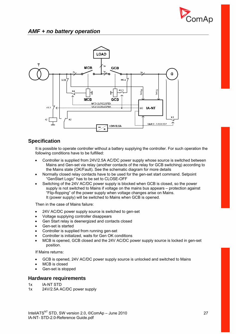
AMF + no battery operation
3xU
M
3xU
G
Specification It is possible to operate controller without a battery supplying the controller. Fofollowing conditions have to be fulfilled:
r such operation the
switched between ing) according to
m for more details ontacts have to be used for the gen-set start command. Setpoint
locked when GCB is closed, so the power e on the mains bus appears – protection against voltage changes arise on Mains.
to Mains when GCB is opened.
/DC power supply source is switched to gen-set supplying controller disappears
upplied from running gen-set • d, waits for Gen OK conditions
B closed and the 24V AC/DC power supply source is locked in gen-set
If Mains
• GCB is opened, 24V AC/DC power supply source is unlocked and switched to Mains • MCB is closed • Gen-set is stopped
Hardware requirements 1x IA-NT STD 1x 24V/2.5A AC/DC power supply
• Controller is supplied from 24V/2.5A AC/DC power supply whose source is Mains and Gen-set via relay (another contacts of the relay for GCB switchthe Mains state (OK/Fault). See the schematic diagra
• Normally closed relay c“GenStart Logic” has to be set to CLOSE-OFF
• Switching of the 24V AC/DC power supply is bsupply is not switched to Mains if voltag
ng” of the power supply when“Flip-floppiIt (power supply) will be switched
Then in the case of Mains failure:
• 24V AC• Voltage • Gen Start relay is deenergized and contacts closed
started • Gen-set is• Controller is s Controller is initialize• MCB is opened, GC
position.
returns:

InteliATSNT STD, SW version 2.0, ©ComAp – June 2010 28 IA-NT- STD-2.0-Reference Guide.pdf
Controllers in cascade
Gen
Sta
rt/S
top
Gen
Sta
rt/St
op
Load
Gen
read
yToL
oad
GTo
enre
ady
3xU
M
3xU
G3x
I GG
en S
tart/
Stop
Gen
read
yToL
oad
Specification Controllers are suitable for “Cascading” applications allowing load to be split intoThe followi ave to be fulfilled:
more sections.
• Automatic remote gen-set start when the mains fails (AUT mode) • Cascade controlled by Master • Consequent changeover on slave controllers • Simple wiring
Hardw re requirements 1 x IA-NT PWR (1 to n) x IA-NT PWR or STD
ng conditions h
a

InteliATSNT STD, SW version 2.0, ©ComAp – June 2010 29 IA-NT- STD-2.0-Reference Guide.pdf
Cascade, wiring B, Mains Fail timing diagram with configuration description
Cascade, wiring B, Mains Return timing diagram with configuration description
InteliATSNT STD, SW version 2.0, ©ComAp – June 2010 30 IA-NT- STD-2.0-Reference Guide.pdf
d
o install
Getting Starte
How t
General To en
• Wiring for binary inputs and analog inputs must not be run with power cables. Binary inputs should use shielded cables, especially when length >3m.
36VDC. Maximum allowable power supply voltage VDC. The InteliATSNT’s power supply terminals are protected against large pulse power
ditions outside its
sure proper function:
•
Power supply To ensure proper function:
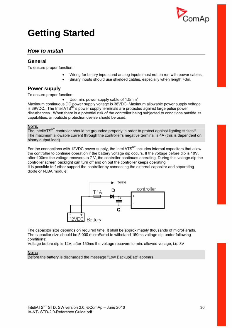
• Use min. power supply cable of 1.5mm2 Maximum continuous DC power supply voltage is is 39disturbances. When there is a potential risk of the controller being subjected to concapabilities, an outside protection devise should be used. NOTE: The InteliATS controller should be grounded properly in order to protect against lighNT ting strikes!! The maximum allowable current through the controller’s negative terminal is 4A (this is dependent on binary output load). For the connections with 12VDC power supply, the InteliATSNT includes internal capacitors that allow the controller to continue operation if the battery voltage dip occurs. If the voltage before dip is 10V, after 100ms the voltage recovers to 7 V, the controller continues operating. During this voltage dip the controller screen backlight can turn off and on but the controller keeps operating. It is possible to further support the controller by connecting the external capacitor and separating diode or I-LBA module:
The capacitor size depends on required time. It shall be approximately thousands of microFarads. The capacitor size should be 5 000 microFarad to withstand 150ms voltage dip under following conditions: Voltage before dip is 12V, after 150ms the voltage recovers to min. allowed voltage, i.e. 8V NOTE: Before the battery is discharged the message "Low BackupBatt" appears.
InteliATSNT STD, SW version 2.0, ©ComAp – June 2010 31 IA-NT- STD-2.0-Reference Guide.pdf
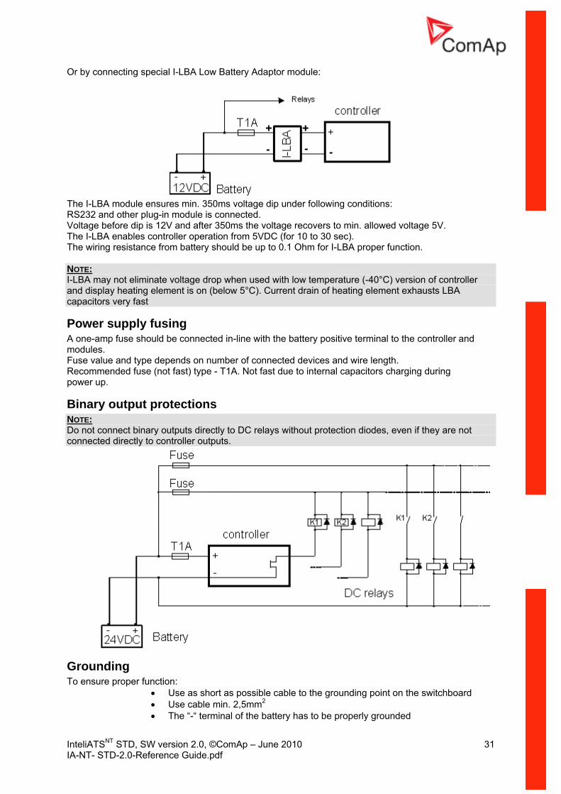
Or by connecting special I-LBA Low Battery Adaptor module:
The I-LBA module ensures min. 350ms voltage dip under following conditions:
Voltage before dip is 12V and after 350ms the voltage recovers to min. allowed voltage 5V.
n.
RS232 and other plug-in module is connected.
The I-LBA enables controller operation from 5VDC (for 10 to 30 sec). The wiring resistance from battery should be up to 0.1 Ohm for I-LBA proper functio N :OTE I-LBA may not eliminate voltage drop when used with low temperature (-40°C) version of controller and display heating element is on (below 5°C). Current drain of heating element exhausts LBA capacitors very fast
nected in-line with the battery positive terminal to the controller and
value and type depends on number of connected devices and wire length. ng during
Binary output protections
Power supply fusing A one-amp fuse should be conmodules. FuseRecommended fuse (not fast) type - T1A. Not fast due to internal capacitors chargipower up.
NOTE: Do not connect binary outputs directly to DC relays without protection diodes, even if they are not connected directly to controller outputs.
Grounding To ensure proper function:
• Use as short as possible cable to the grounding point on the switchboard • Use cable min. 2,5mm2 • The “-“ terminal of the battery has to be properly grounded
InteliATSNT STD, SW version 2.0, ©ComAp – June 2010 32 IA-NT- STD-2.0-Reference Guide.pdf
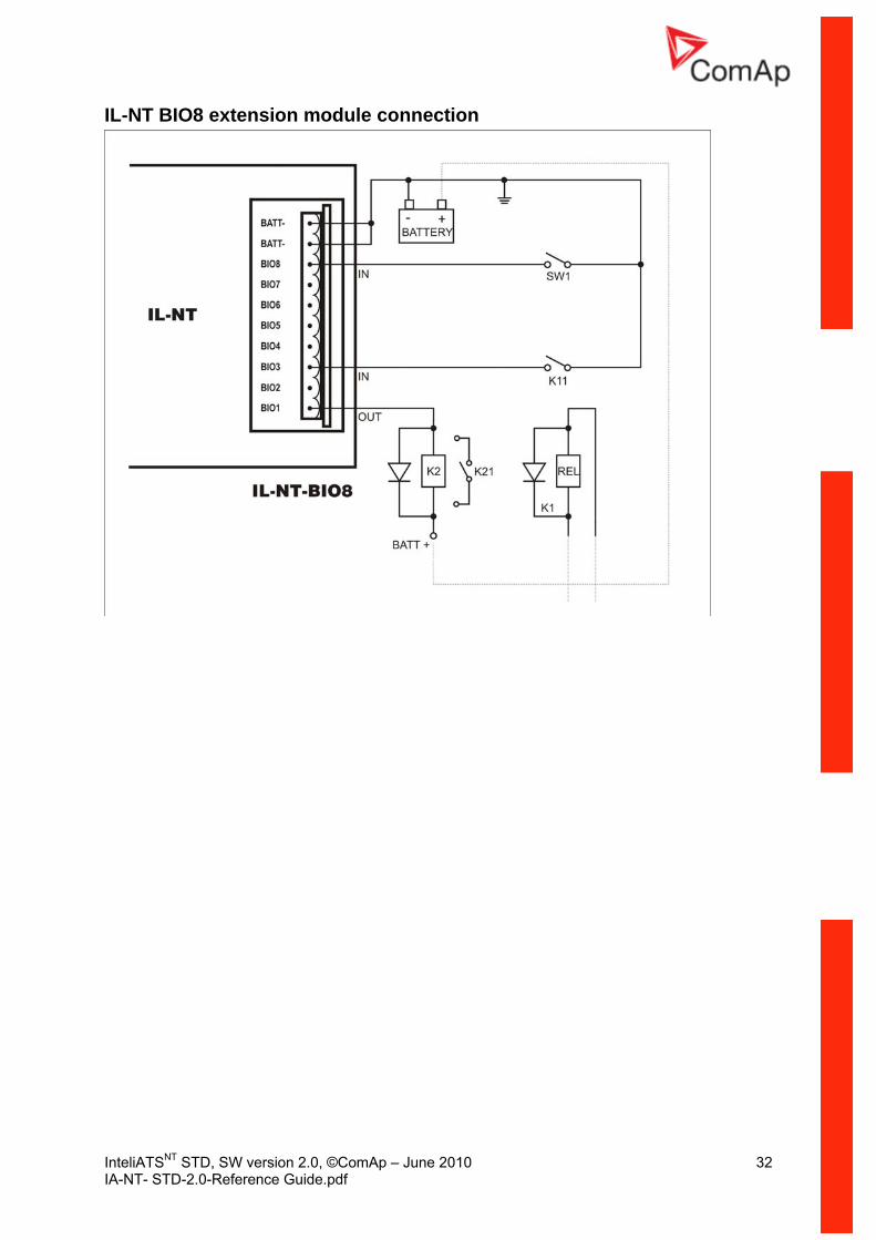
IL-NT BIO8 extension module connection

InteliATSNT STD, SW version 2.0, ©ComAp – June 2010 33 IA-NT- STD-2.0-Reference Guide.pdf
Three phase applications
Voltage measurement
G
GENERATOR MAINSL3L2L1N
L1L2L3
N
L3L2L1N
G
GENERATOR MAINSL3L2L1N
L1L2L3
L3L2L1N
NOTE: No separation transformers for three wires voltage connection (without N) are needed. Switchboard lighting strikes protection according standard regulation is expected!!!
Single phase applications There is not a separate archive file for single-phase applications. Use standard ail archives.
Recommended wirings Generator (and mains) single-phase voltage has to be connected to all three-voltage terminals L1, L2 and L3.
Voltage measurement
G
GENERATOR MAINS
L3L2L1N
LN
L3L2L1N
NOTE: Switchboard lighting strikes protection according standard regulation is expected!!!

InteliATSNT STD, SW version 2.0, ©ComAp – June 2010 34 IA-NT- STD-2.0-Reference Guide.pdf
Binary inputs
Binary outputs
+
Battery
-
iL4k7 Ω
+ -PowerSupply
+
Battery
-
iLLOAD
+ -PowerSupply
InteliATSNT STD, SW version 2.0, ©ComAp – June 2010 35 IA-NT- STD-2.0-Reference Guide.pdf
ts nputs/Outputs overview table see chapter Technical Data.
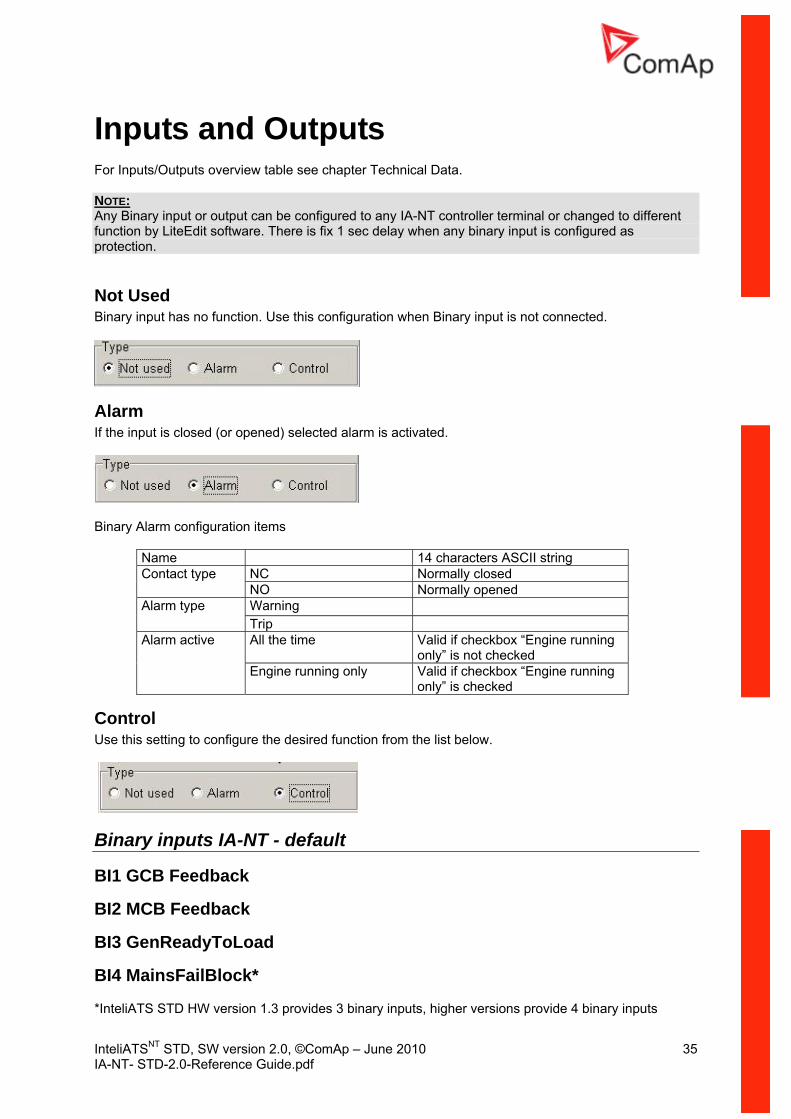
Inputs and OutpuFor I NOTE: Any Binary input or output can be configured to any IA-NT controller terminal or changed to different function by LiteEdit software. There is fix 1 sec delay when any binary input is configured as protection.
Not Used Binary input has no function. Use this configuration when Binary input is not connected.
Alarm If the input is closed (or opened) sel d alarm is activated. ecte
Bina nfigu ms
string
ry Alarm co ration ite
Name 14 characters ASCIINC Normally closed Contact typeNO ally opened
Norm
Warning Alarm type Trip All the time Valid if checkbox “Engine running
only” is not checked Alarm active
Engine running only Valid if checkbox “Engine running only” is checked
Control Use this setting to configure the desired function from the list below.
Binary inputs IA-NT - default
BI1 GCB Feedback
BI2 MCB Feedback
BI3 GenReadyToLoad
BI4 MainsFailBlock*
*InteliATS STD HW version 1.3 provides 3 binary inputs, higher versions provide 4 binary inputs

InteliATSNT STD, SW version 2.0, ©ComAp – June 2010 36 IA-NT- STD-2.0-Reference Guide.pdf
Binary inputs – list
Rem Start/Stop External request for engine run. AUT mode only.
NOTE: If the binary input Rem Start/Stop is active and mains failure occures, the MCB breaker opens, and after AMF Settings: Trans Del delay the GCB breaker is closed. Once the mains is OK, the AMF Settings: MainsReturnDel delay elaspes and the GCB breaker is opened. Then after AMF Settings: Trans Del delay is MCB breaker closed. Gen-set remains running as long as Rem Start/Stop is active. See AMF time chart for more details.
Rem Transfer External request for an immediate transfer from mains to generator without waiting for the AMF
m will stay in
ion of the MODE
e lowest priority.
se of running
her the gen-set is ready to undertake load. Conditions for successful gen-set start and tpoint – evaluated
rom the state of GenReadyToLoad input. The o be fulfilled during time defined by AMF Settings: Max Start Del setpoint (which can
input switches a three position ATS switch to its neutral position – it activates the MCB and GCB off.
ack
MCB Feedback This input indicates whether MCB is closed or opened.
MainsHealthy This iinp s creted mainly for cascading applications, where slave controllers do not have usually Mains and Gen-set voltage measuring inputs connected to the repspective power sources.Then this binary input tells the controller if Mains is healthy to be able to respond to Mains failure.
Settings: EmergStart Del has elapsed. In the case the transfer not succeeded the systeneutral position. The MainsFailBlock input performs its work normally.
Remote AUTIf the input is active, AUTO mode is forced to the controller independently on the positselector. If another of remote inputs is active, then the REMOTE AUT input has th
MainsFailBlock If the input is closed, the automatic start of the gen-set at Mains failure is blocked. In cagen-set the GCB is opened, gen-set goes to Cooling procedure and stops.
GenReadyToLoad Indicates wetreadiness to undertake load can be – depending on AMF Settings: GenerProtect sefrom the voltage and the frequency of the generator or fconditions have tbe even unlimited). More info can be found in the setpoint description.
Neutral Pos In MAN mode thisbinary output NeutralPosition and switches the
GCB FeedbUse this input for indication, whether the generator circuit breaker is open or closed. If the feedback is not used, connect this input to the output GCB CLOSE/OPEN
ut wa
InteliATSNT STD, SW version 2.0, ©ComAp – June 2010 37 IA-NT- STD-2.0-Reference Guide.pdf
Binary outputs IA-NT - default
BO1 GenStart/Stop
pen
/Open
ts - list
BO2 Alarm
BO3 GCB Close/O
BO4 MCB Close
Binary outpu
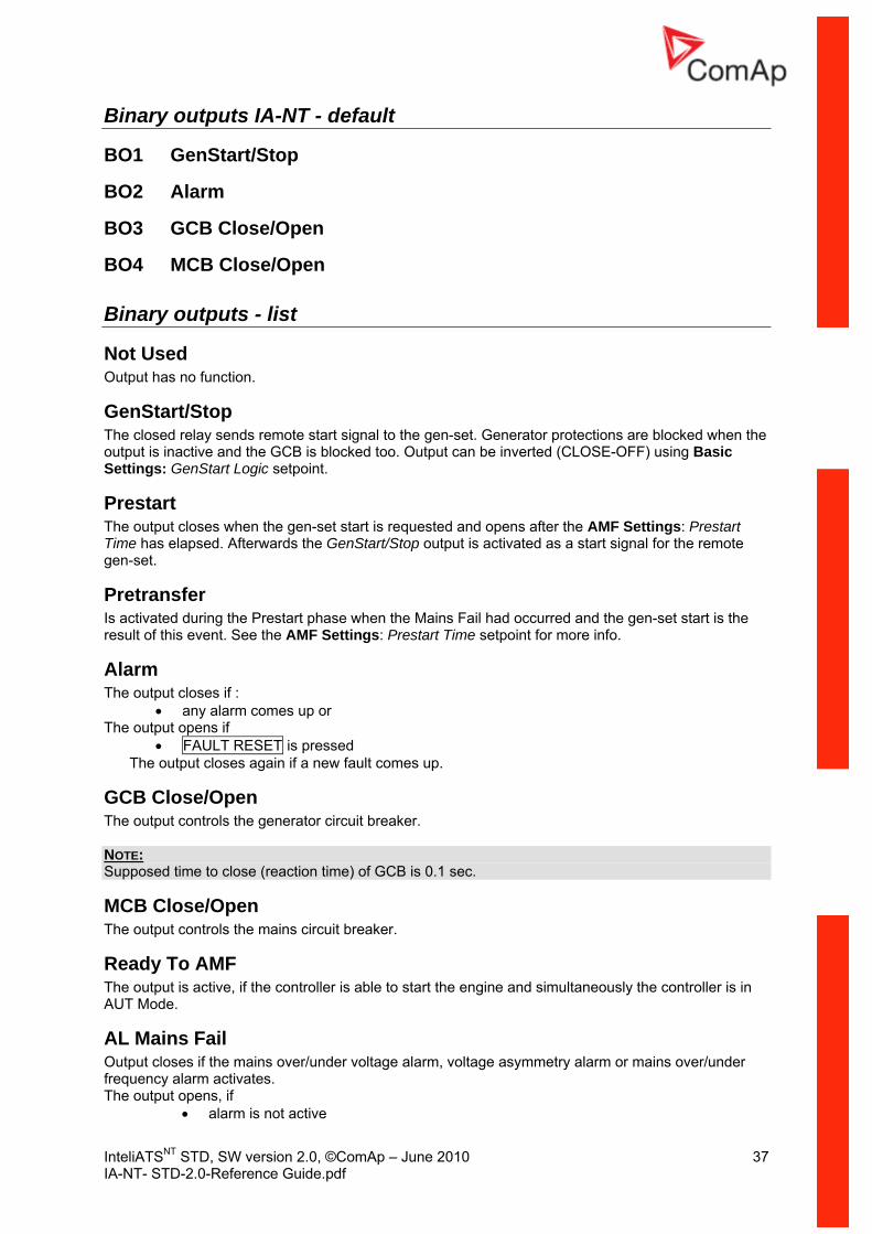
Not Used Output has no function.
GenStart/Stop The closed relay sends remote start signal to the gen-set. Generator protections are blocked when the
) using Basic
ngs: Prestart mote
gen-set.
rt phase when the Mains Fail had occurred and the gen-set start is the Settings: Prestart Time setpoint for more info.
Alarm :
pens if
output is inactive and the GCB is blocked too. Output can be inverted (CLOSE-OFFSettings: GenStart Logic setpoint.
Prestart The output closes when the gen-set start is requested and opens after the AMF SettiTime has elapsed. Afterwards the GenStart/Stop output is activated as a start signal for the re
Pretransfer Is ac aresu of
tiv ted during the Prestalt this event. See the AMF
The output closes if• any alarm comes up or
The output o• FAULT RESET is pressed
The output closes again if a new fault comes up.
ols the generator circuit breaker. GCB Close/Open The output contr NOTE: Supposed time to close (reaction time) of GCB is 0.1 sec.
mains circuit breaker.
The output is active, if the controller is a art the engine and simultaneously the controller is in AUT Mode.
AL Mains Fail Output closes if the mains over/under voltage alarm, voltage asymmetry alarm or mains over/under frequency alarm activates. The output opens, if
• alarm is not active
MCB Close/Open The output controls the
Ready To AMF ble to st

InteliATSNT STD, SW version 2.0, ©ComAp – June 2010 38 IA-NT- STD-2.0-Reference Guide.pdf
tes when the controller is not in AUT mode.
S switch to its neutral position.
The output is a copy of Fault Reset button on controller and binary input FaultResButton.
Not In AUT Output activa
Neutral Pos Switches AT
Falut Reset

InteliATSNT STD, SW version 2.0, ©ComAp – June 2010 39 IA-NT- STD-2.0-Reference Guide.pdf
s Setpoint
Password
EnterPassword Password is a four-digit number. Password enables change of relevant protected setpoints.
key to enter the password. Use ↑ or ↓ keys to set and ENTER NOTE: There is only 1 level of a password.
ChangePassword Use ↑ or ↓ keys to set and ENTER key to change the password. NOTE: At first the password has to be entered before the new password can be changed.
Basic Settings
ControllerN ma e NTUser de d namefine , used for Inteli identification at remote phone or mobile connection.
llerN 14 characters long and have to be entered using LiteEdit software.
eq [Hz]
: 65 Hz
e [s] ut prior to the engine start.
zero t to leave the output Prestart/Pretzransfer open.
:
MaxStartDel [s] This timeout starts after closing binary output GEN START/STOP. When generator does not reach defined limits Basic Settings: Nominal Freq) within MaxStartDel, Trp Start Fail alarm occurs and the gen-set will shut down. See the table below for a description of the engine start evaluation. If MaxStartDel is longer then 600 s it means there is NO TIMEOUT. Step: 1s Range: 0 – 600 s, 601 s = NO TIMEOUT
Contro ame is max
Nominal Fr Nominal generator frequency (usually 50 or 60 Hz )
1Hz Step: Range 45 –
Prestart Tim Tim inge of clos of the Prestart and/or Pretransfer outpSet to if you wanStep: 1s Range: 0 – 600 s
Cooling Time [s] e stop. Runtime of the unloaded gen-set to cool the engine befor
1s Step: Range 0 – 3600 s

InteliATSNT STD, SW version 2.0, ©ComAp – June 2010 40 IA-NT- STD-2.0-Reference Guide.pdf
Engine start evaluation diagram:
MinStabTime [s] Minimum time interval between defined generator voltage is reached to GCB is clIf BI: GenReadyToLoad is not configured, timer is not used. Step: 1s
: 1 – 300 s
osed.
Stop Time troller how long should it wait for the ToLoad signal is deactivated or
he stop time expires the Trp Stop i controller sends Stop command to (S
Step: 1s Range: – 3601 sec Value 360 n he controller doesn’t care for the engine is
stopped (Trp Stop Fail is never announced).
GenStart Logic [CLOSE-ON/CLOSE-OFF] The set point influences the behavior of the output Gen Start/Stop. CLOSE-ON: Gen-set should start when the output Gen Start/Stop is closed. CLOSE-OFF: Gen-set should start when the output Gen Start/Stop is opened.
Range
[s] Period given by the value of the Stop Time setpoint tells the conengine to change to to te (stop state means GenReady the s p sta
r vgenerato oltages disappeared). If the engine is still running after tFail alarm s announced. Stop Fail starts counting always when the the engine tart/Stop output is deactivated).
0 1 mea s t
InteliATSNT STD, SW version 2.0, ©ComAp – June 2010 41 IA-NT- STD-2.0-Reference Guide.pdf
[V] th
setpoint expires, the engine is started and is running as long as setpoint. Test Period starts counting always when the engine is stopped.
da s
[min] when engine is running after expiring the Test Period setpoint.
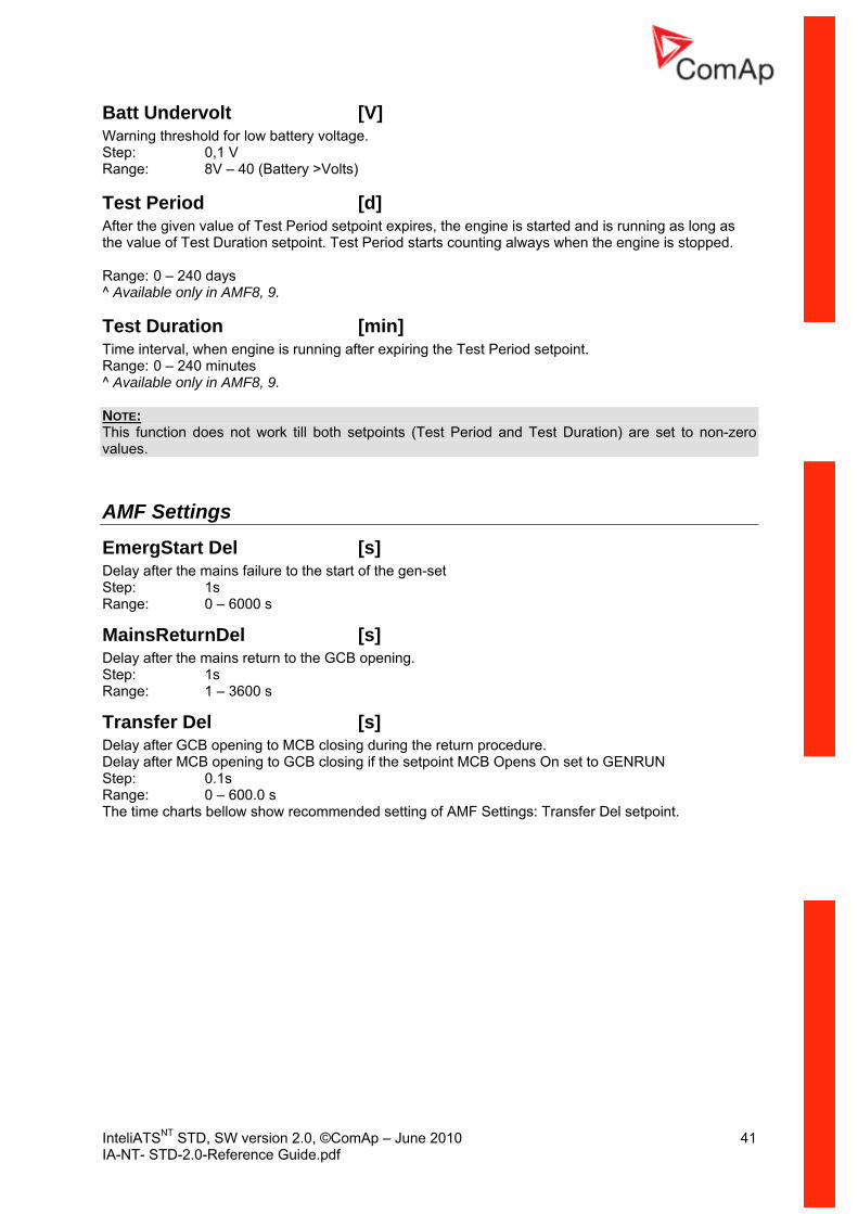
Batt Undervolt Warning reshold for low battery voltage. Step: 0,1 V Range: 8V – 40 (Battery >Volts)
Test Period [d] After the given value of Test Period the value of Test Duration Range: 0 – 240 y^ Available only in AMF8, 9.
Test Duration Time interval,Range: 0 – 240 minutes ^ Available only in AMF8, 9.
NOTE: This function does not work till both setpoints (Test Period and Test Duration) are set to non-zero values.
AMF Settings
EmergStart Del [s] the gen-set
s
Transfer Del [s] Delay after GCB opening to MCB closing during the return procedure. Delay after MCB opening to GCB closing if the setpoint MCB Opens On set to GENRUN Step: 0.1s Range: 0 – 600.0 s The time charts bellow show recommended setting of AMF Settings: Transfer Del setpoint.
Delay after the mains failure to the start ofStep: 1s Range: 0 – 6000
MainsReturnDel [s] Delay after the mains return to the GCB opening. Step: 1s Range: 1 – 3600 s

InteliATSNT STD, SW version 2.0, ©ComAp – June 2010 42 IA-NT- STD-2.0-Reference Guide.pdf
shor eedback of t se/Open G ansfer Del
100 must be set to sum of “MCB opening” + “del” after the MCB feedback input deactivates. time.
V [V] hree is used.
: – 300V
[V] hree is used.
hold f ll three phases are checked. Maximum out of three is used. ency
Main <Freq
Threshold for mains underfrequency. All three phases are checked. Maximum out of three is used.
ens On [MAINSFAIL / GENRUN]
If the Transfer Del setpoint is set ter If some delay between MCB fthan the time required for opening he deactivation and closing o f GCB Clocircuit breaker, the controller closes CB output is required, then the TrClose/Open output straight away ( ms)
MCB Close/Open
MCB Feedback
GCB Close/Open
MCB opening del
Transfer Del
M
CB lose/Open
MCB Feedback
GCB Close/Open
C
Mains >Threshold for mains overvoltage. All three phases are checked. Maximum out of t
V Step: 1Range (Mains <V)
Mains <V Threshold for mains undervoltage. All three phases are checked. Maximum out of tStep: 1V Range: 50V - (Mains >V)
Mains >Freq [%] Thr s or mains overfrequency. e AStep: 0.1% of Nominal frequRange: 50 ( s ) – 150.0%
Mains <Freq [%]
Step: 0.1% of Nominal frequency Range: 50% – 150.0(Mains >Freq)%
MCB OpMAINSFAIL
ed.
GENRUN
The command to open the MCB is given immediately after mains fail condition evaluat
The command to open the MCB is not given till the Gen-set starts (with respecting the setpoint EmergStart Del), reaches Running state, reaches proper voltage and frequency and Min Stab Time elapses. After that, the MCB is opened, Transfer Del timer is started and the GCB is closed after the timer elapses. NOTE: This option should be used for MCBs using 230V control and not equipped with the undervoltage coil.
Transfer Del
MCB opening
InteliATSNT STD, SW version 2.0, ©ComAp – June 2010 43 IA-NT- STD-2.0-Reference Guide.pdf
on Function Descripti
Operating modes Selection of the operating mode is done through Mode buttons on the front panel or by changing of the Controller mode setpoint (from the front panel or remotely).
NOTE: If this setpoint is configured as password-protected, correct password must be entered prior attempting to change the mode. T r g binary inputs that can be used to force one respective operating mode he e are followinindependently on the mode setpoint selection:
• Remote AUT
If the respective input is active the controller will change mode to the respective position according to ctive input. If more inputs are active the mode will be changed according to priorities of the
mode will
ne can be started and stopped manually using START and STOP buttons (or external buttons wired to appropiate binary inputs) in MAN mode. This will activate/deactivate GenStart/Stop
the ainputs. The priorities matches the order in the list above. If all inputs are deactivated thereturn to the original position given by the setpoint.
MAN The engi
binary output which polarity depends on GenStart Logic setpoint. When the engine is running, Gclosed to a dead bus. Also MCB can be closed and opened manually using the MCB buregardless the mains is present or not. No autostart is performed. No re
CB can be tton,
action to the input Rem Start/Stop.
NOTE: The engine can run without load unlimited time. The controller does not automatically stop the running gen-set in MAN Mode and does not start the gen-set when power cut comes. NOTE: The breakers are internally locked to close two voltages against each. The controller will automatically recognize if the breaker can be closed, it means it is never possible to close both breakers together NOTE: If some voltage arises on generator bus (e.g. gen-set was started externally - not via IA-NT), generator LED blinks and [Stop], [MCB], [GCB] buttons are inactive. To bring them into operation [Start] button has to be pressed - it will synchronize IA-NT with gen-set state. CAUTION! The MCB can be opened manually in MAN mode. Accidental opening the MCB will cause the object (load) will remain without power!!!
AUT The engine is started and stopped either by the binary input Rem Start/Stop or by the AMF mechanism or by the manual transfer request via Rem Transfer binary input. Buttons MCB, GCB, START, STOP including the appropriate binary inputs for external buttons are not active. The full start sequence up to the moment when th in loaded is automatic as well as unloading and stop sequence. The controller behavior when gen-set is stopped and restarted again whilst the mains failure constantly persists: • If the problem on the gen-set side appears, all faults messages are auto-quit and no next
operation is be blocked • Gen-set Start/Stop signal stays active
e eng e is
InteliATSNT STD, SW version 2.0, ©ComAp – June 2010 44 IA-NT- STD-2.0-Reference Guide.pdf
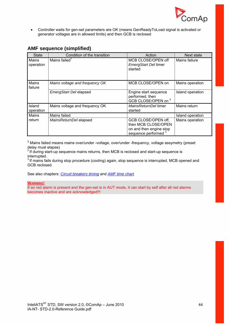
GenReadyToLoad signal is activated or generator voltages are in allowed limits) and then GCB is reclosed
AMF sequen
• Controller waits for gen-set parameters are OK (means
ce (simplified) State Condition of the transition Action Next state
Mains operation
Mains failed1 MCB CLOSE/OPEN off
EmergStart Del timer Mains failure
started
Mains voltage and frequency OK CLOSE/OPEN on Mains operation MCB
Mains failure
art sperformed, th
E
Island operation EmergStart Del elapsed
Engine st equence en /OPEN on 2GCB CLOS
Island operation
uency OK D Mains return Mains voltage and freq MainsReturnstarted
el timer
Mains failed Island operation Mains return
e stop
3
Mains operation MainsReturnDel elapsed GCB CLOSE/OPEN off, then MCB CLOSE/OPENon and then enginsequence performed
1 Mains failed means mains over/under -voltage, over/under -frequency, voltage assymetry (preset
closed and start-up sequence is ed.
, MCB opened and
See also chapters: Circuit breakers timing
delay must elapse) 2 If during start-up sequence mains returns, then MCB is reinterrupt3 If mains fails during stop procedure (cooling) again, stop sequence is interruptedGCB reclosed.
and AMF time chart.
WARNING! If an red alarm is present and the gen-set is in AUT mode, it can start by self after all red alarms becomes inactive and are acknowledged!!!
InteliATSNT STD, SW version 2.0, ©ComAp – June 2010 45 IA-NT- STD-2.0-Reference Guide.pdf
ing Circuit breakers tim
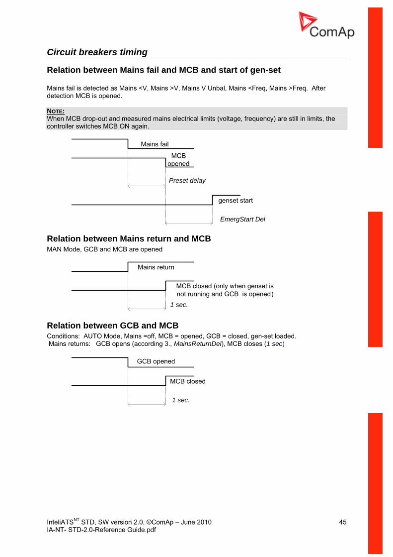
Relation between Mains fail and MCB and start of gen-set
s >Freq. After ned.
Mains fail is detected as Mains <V, Mains >V, Mains V Unbal, Mains <Freq, Maindetection MCB is ope NOTE: When MCB drop-out and measured mains electrical limits (voltage, frequency) are still in limits, the controller switches MCB ON again.
EmergStart Del
Mains fail
MCB opened
Preset delay
genset start
Relation between Mains return and MCB MAN Mode, GCB and MCB are opened
Mains return
MCB closed (only when genset is not running and GCB is opened)
1 sec.
Relation between GCB and MCB Conditions: AUTO Mode, Mains =off, MCB = opened, GCB = closed, gen-set loaded. Mains returns: GCB opens (according 3., MainsReturnDel), MCB closes (1 sec)
GCB opened
MCB closed
1 sec.
InteliATSNT STD, SW version 2.0, ©ComAp – June 2010 46 IA-NT- STD-2.0-Reference Guide.pdf
nt re available:
• Trip re
Alarm ManagemeFollowing alarms a
• Warning
• Mains failu
Warning (WRN) When warning comes up, only alarm outputs and common warning output are closed.
warnings: ossible events
PossibleSee List of p
Trip (TRP) When the trip alarm comes up, InteliATSNT opens outputs GCB CLOSE/OPEN, GENSTART/STOP
p the engine immediately. Alarm outputs and common shutdown output are closed. Active or not reset protection disables start.
s:
and PRESTART to sto
Possible shut-down alarmSee List of possible events
Mains failure (MF) Mains failure detection depends on Auto mains failure (AMF) setpoints (levels and delays) adjusting.
p, mains circuit breaker is opened.
Possible mains failure reasons: See List of possible events
When the mains failure comes u
NOTE: Mains failure is not written to alarm list!
InteliATSNT STD, SW version 2.0, ©ComAp – June 2010 47 IA-NT- STD-2.0-Reference Guide.pdf
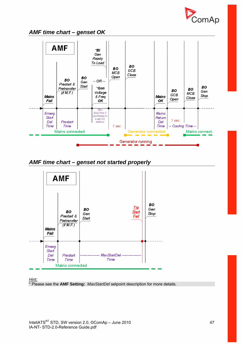
AMF time chart – genset OK
AMF time chart – genset not started properly
Hint: * Please see the AMF Setting: MaxStartDel setpoint description for more details.
InteliATSNT STD, SW version 2.0, ©ComAp – June 2010 48 IA-NT- STD-2.0-Reference Guide.pdf
Voltage phase sequence detection InteliATSNT controller detects phase sequence on both generator and mains/bus vThese protections are important after c
oltage terminals. ontroller installation to avoid wrong voltage phases phase
s can be detected:
The T controller L1, L2, L3. When the phases are conn 2, L1, L3) following alarms are detected:
Gen CCW Rot = wrong generator phase sequence Mains CCW Rot = wrong mains phase sequence
connection. Following alarm
Wrong phase sequence re is fix defined phase sequence in InteliATSN
ected in different order (e.g. L1, L3, L2 or L
InteliATSNT STD, SW version 2.0, ©ComAp – June 2010 49 IA-NT- STD-2.0-Reference Guide.pdf
tes ic sper
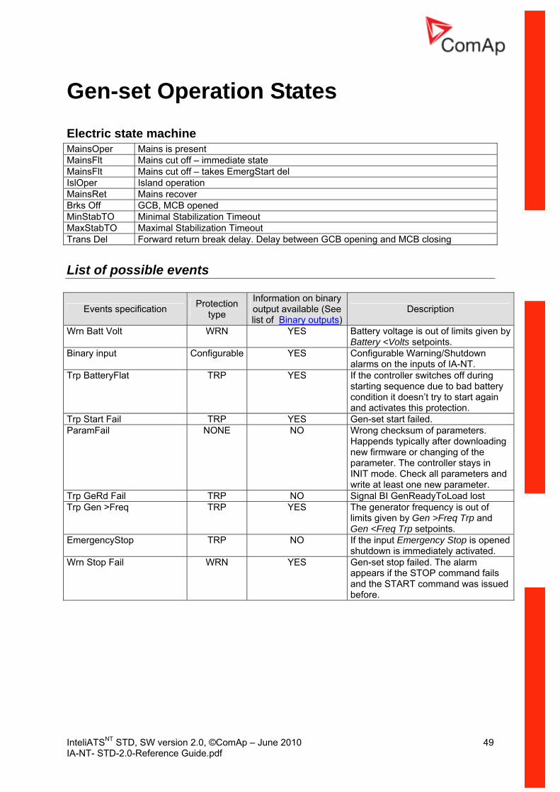
Gen-set Operation StaElectr tate machine MainsO Mains is present MainsFlt off – immediate state Mains cut MainsFlt – takes EmergStart del Mains cut off IslOper Island operation MainsRet Mains recover Brks Off GCB, MCB opened MinStabTO Minimal Stabilization Timeout MaxStabTO Maximal Stabilization Timeout Trans Del Forward return break delay. Delay between GCB opening and MCB closing
List of possible events
Events specification Protection type
Information on binary output available (See list of Binary outputs)
Description
Wrn Batt Volt WRN YE of limits given by ints.
S Battery voltage is outBattery <Volts setpo
Binary input Configurable YE arning/Shutdown S Configurable Walarms on the inputs of IA-NT.
Trp BatteryFlat TRP YE es off during to bad battery
try to start again ection.
S If the controller switchstarting sequence duecondition it doesn’tand activates this prot
Trp Start Fail TRP YE . S Gen-set start failedParamFail NONE NO of parameters.
after downloading anging of the
ller stays in ll parameters and
e new parameter.
Wrong checksumHappends typicallynew firmware or chparameter. The controINIT mode. Check awrite at least on
Trp GeRd Fail TRP NO oLoad lost Signal BI GenReadyTTrp Gen >Freq TRP YE cy is out of
limits given by Gen >Freq Trp and Gen <Freq Trp setpoints.
S The generator frequen
EmergencyStop TRP NO If the input Emergency Stop is opened shutdown is immediately activated.
Wrn Stop Fail WRN YES Gen-set stop failed. The alarm appears if the STOP command fails and the START command was issued before.
InteliATSNT STD, SW version 2.0, ©ComAp – June 2010 50 IA-NT- STD-2.0-Reference Guide.pdf
ging Remote Control and Data Log
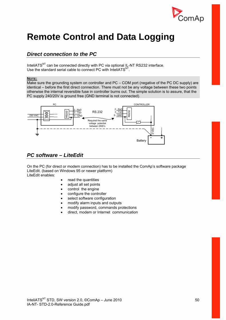
Direct connection to the PC InteliATSNT can be connected directly with PC via optional IL-NT RS232 interface. Use the standard serial cable to connect PC with InteliATSNT. NOTE: Make sure the grounding system on controller and PC – COM port (negative of the PC DC supply) are identical – before the first direct connection. There must not be any voltage between these two points otherwise the internal reversible fuse in controller burns out. The simple solution is to assure, that the PC supply 240/20V is ground free (GND terminal is not connected).
5 - GND
2 - RxD3 - TxD
PC
5 - GND
2 - RxD3 - TxD
RS2
32
RS2
32
230 VAC
0 VD
C
CONTROLLER
+-Battery
Required the samevoltage potentialbetween GND‘s
RS 232
PC software – LiteEdit On the PC (fo n) has to be installed the ComAp’s software package LiteEd rm) LiteEdit enabl
• control the engine • configure the controller • select software configuration • modify alarm inputs and outputs • modify password, commands protections • direct, modem or Internet communication
r direct or modem connectioit. (based on Windows 95 or newer platfo
es: • read the quantities • adjust all set points

InteliATSNT STD, SW version 2.0, ©ComAp – June 2010 51 IA-NT- STD-2.0-Reference Guide.pdf
ion Remote CommunicatNOTE: Refer to InteliCommunication guide for all additional information.
Internet connection
ed from InteliMonitor or LiteEdit over the Internet using IB-Lite
DN modem
IA-NT controllers can be monitorplug-in.
Recommended IS
• Askey TAS-200E • ASUScom TA-220ST • Develo Microlink ISDN i
Recommended GSM modem
• Siemens M20, TC35, TC35i, ES75, MC39 200/WMOD2
T recommended) 0MHz.
etup n following program for GSM proper setup.
configure the GSM modem properly for use with
• Start MS Windows-Start-Program files - LiteEdit –Gm_setup.exe. Select COM port
ress S
• Wavecom M1• Wavecom - Maestro 20, dual 900/1800MHz. • Wavecom – Fastrack M1306B, dual 900/1800 MHz (Fastrack M1206B is NO• FALCOM A2D, dual 900/180
GSM Modem sPrio to start work with GSM modem rurProgram writes all the necessary AT commands toIA-NT. This program runs independent on LiteEdit:
•• Select iG-CU (=IS-CU) or iG-MU unit • P etup button
Follow command M Modem Setup w Typical real baud rate for GSM data communication is 80 to 90 Bps.
s in GS indow •
NOTE: It is strongly recommended to use the same type of modem on the both sides (IA and PC) of connection.
Analog Analog modem
GSM modem
GSM modem or modem
Mobile SIM card setting
• Adjust SIM card in GSM modem following way: • enable data connection (when required) • no PIN code
InteliATSNT STD, SW version 2.0, ©ComAp – June 2010 52 IA-NT- STD-2.0-Reference Guide.pdf
ware mote signalling
and control software for InteliATS , InteliLite and InteliDrive Lite controllers. It is the optional ible to upload into controller instead of standard controller’s firmware.
IL-NT-RD Remote display softThis chapter describes Remote display software IL-NT-RD, which is designed as an re
NT NT
software which is poss
General description Remote display software works as “remote display and control” for the master InteliATor InteliDrive Lite controller. Genset/Engines can be controlled
SNT, InteliLiteNT from remote display as well as from
master controller. All remote display screens (Measure, Setpoints and History) displays the same data r. Front panel buttons on both controllers work the same way. All remote display like master controlle
LED’s shows the same state as corresponding LED’s on master controller.
Warning ! It is highly recommended to use the same type and model of controller for master and remote
d the proper function of all buttons, LED diods and display. play are
display. Only in such case is assureAnother combinations of HW types and models from Master controller and remote disnot supported nor tested!
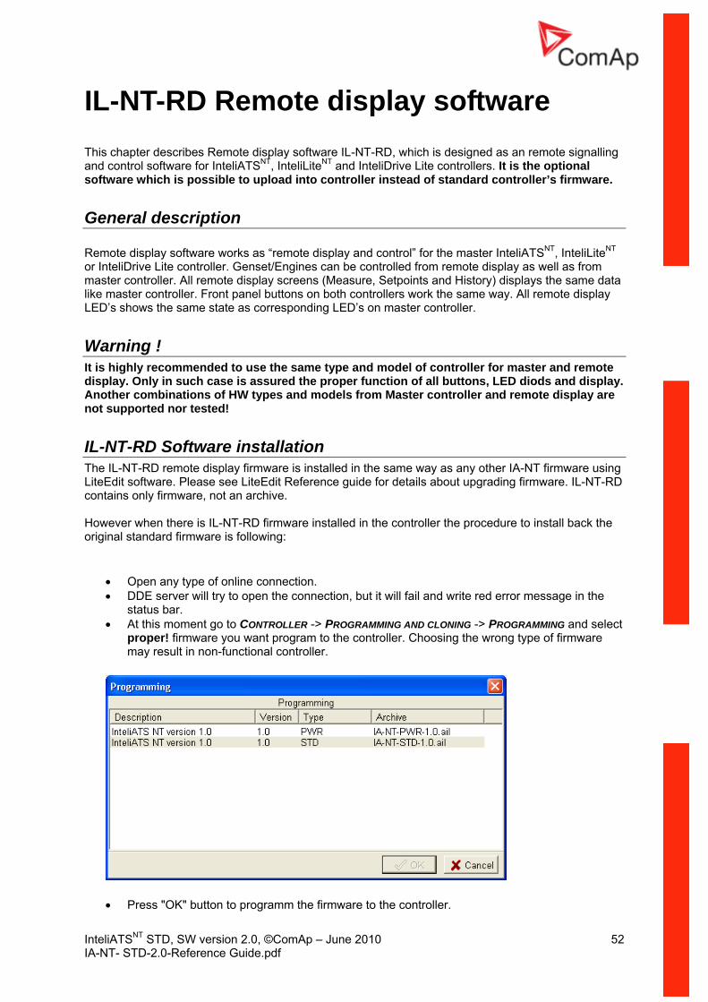
IL-NT-RD Software installation The IL-NT-RD remote display firmware is installed in the same way as any other IA-NT firmware using LiteEdit software. Please see LiteEdit Reference guide for details about upgrading firmware. IL-NT-RD
.
back the
• Open any type of online connection. • DDE server will try to open the connection, but it will fail and write red error message in the
status bar. • At this moment go to CONTROLLER -> PROGRAMMING AND CLONING -> PROGRAMMING and select
proper! firmware you want program to the controller. Choosing the wrong type of firmware may result in non-functional controller.
contains only firmware, not an archive However when there is IL-NT-RD firmware installed in the controller the procedure to install original standard firmware is following:
• Press "OK" button to programm the firmware to the controller.

InteliATSNT STD, SW version 2.0, ©ComAp – June 2010 53 IA-NT- STD-2.0-Reference Guide.pdf
oller, close the boot jumper and switch
• r cess
ns. • tus line and the
controller is blocked showing "Init" state. Use CONTROLLER -> RESET FROM INIT STATE menu item to put the controller to normal operation. Be sure you have checked all setpoints before.
• It may be required to switch off power supply of contron controller again. Follow the information windows accordingly.
After programming is finished (it may be required to power off controller, open the boot jumpeand power it on again) open configuration window and perform the configuration promanually. There is no compatibility of the configuration between different firmware versio
In some cases the "wrong setpoints" message can occur in the DDE server sta
CAUTION! Check the statistic value
s after firmware upgrade. Readjust the values if necessary.
IL-NT-RD Wiring IL-NT-RD can be connected to InteliATSNT, InteliLiteNT or InteliDrive Lite controllerRS485 communication line. It is possibl
via RS232 or e to connect only up to two remote displays to one master
ing different communication COMs. It is not supported to connect two or more one master
nnected. It ntrollers address 1 to 32 and later on COM2 from address 1
to 32. Remote display tries two communication speeds 38400 bps and 56000bps.
Detecting…” on screen and progress bar below counts from 0 to prox. 10-15 seconds. Than is 5 seconds pause and process continues
llers, not supported application, or controllers that are not properly
mote display can not connect with master controller: o uppo ed type of controller connected (Eg. IGS-NT, ID-DCU, IC-NT, IGS-CU, etc.)
d firmwa ller tab roller
4. Wrong settings o in master controller g connectio
Direct RS232 connection HW module: IL-NT-RS232 Master controller settings: ControllerAddr = 1..32
COM1 Mode = DIRECT Up to 2 meters: Reco to use our standard AT-LINK cable.
controller, if they are usremote displays to one communication line, eg. RS485. It is possible to monitor onlycontroller from one remote display at the time.
Connection process Remote display after power on automaticaly starts to search for any master controller costarts to search on COM1 from master co
During this process is displayed text “100%. This process takes apagain until compatible master controller is found. Not supported types of controcomunicating are skipped during the search.
Controller type selection IL-NT-RD automatically detects controller type.
Troubles with connection There are few reasons why re
1. N t s rt2. Not supporte re in master contro3. Configuration le error in master cont
f setpoint COMx Mode5. Wron n, wiring, communication fail
mmended
InteliATSNT STD, SW version 2.0, ©ComAp – June 2010 54 IA-NT- STD-2.0-Reference Guide.pdf
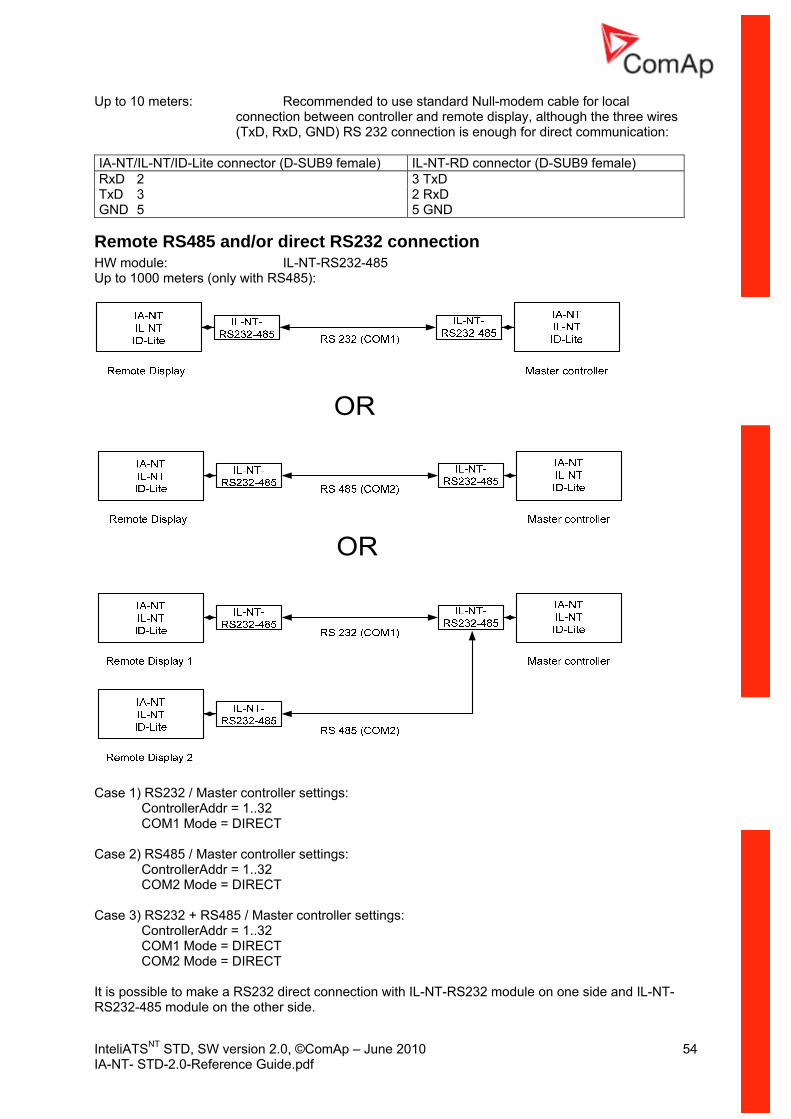
Up to 10 meters: r local the three wires
communication:
L-NT/ID-Lite connector (D-SUB9 fem IL-NT-RD connector (D-SUB9 female)
Recommended to use standard Null-modem cable foconnection between controller and remote display, although(TxD, RxD, GND) RS 232 connection is enough for direct
IA-NT/I ale) RxD 2 3 TxD TxD 3 2 RxD GND 5 5 GND
Remote RS485 and/or direct RS232 connection HW module: IL-NT-RS232-485 Up to 1000 meters (only with RS485):
Case 1) RS232 / Master controller settings:
ControllerAddr = 1..32 ECT
COM2 Mode = DIRECT Case 3) S232 + RS485 / Master controller settings:
ControllerAddr = 1..32 COM1 Mode = DIRECT COM2 Mode = DIRECT
It is possible to make a RS232 direct connection with IL-NT-RS232 module on one side and IL-NT-RS232-485 module on the other side.
COM1 Mode = DIR
Case 2) RS485 / Master controller settings: ControllerAddr = 1..32
R
InteliATSNT STD, SW version 2.0, ©ComAp – June 2010 55 IA-NT- STD-2.0-Reference Guide.pdf
ion using external RS232-RS422/485 converter:
485 bus 0 or 56000 bps.
Any connected RS 232 to RS 422/485 converter has to be set to passive DSR signal (when DSR connected) after switch on.
Alternative connectRecommend external converter: ADVANTECH – ADAM 4520: RS232 to RS422/485 converter, DIN rail, automatic RSsupervision, no external data flow control signals, galvanic isolated, baud rate 3840
Function description Remote display IL-NT-RD works as remote display and control of the master InteInteliDrive Lite controller. It is supposed and highly recommended that both, remote master are using the same HW type and model of controller. Another types and models of mastremote display are not supported nor tested. All remote display
liATSNT, InteliLiteNT or display and
er and ’s LEDs show the same state as
ork in the same ntroller. User can
switch screens, set password, change setpoints and view history records.
Interruption of the serial line between master device and Remote display has no effect to the master
unication cannot be
nfiguration table
After the configuration from master is downloaded remote display jump to master controllers Init
and blinking.
een to check it’s version and serial number of used essing PAGE button for 3 seconds.
SW compatibility
corresponding LEDs on master controller. Front panel buttons on both controllers wway. Genset/Engine can be controlled from remote display as well as from master co
All IL-NT-RD screens Init, Measure, Setpoints and History display the same data like in the master controller. Master device is always able to work without connected Remote display.
controller. If the serial line between master device and remote display is interrupted, or commestablished, remote display shows it’s Init screen and message “Trying” and all LED’s are off.
Once remote display finds compatible master it shows “Preparing” and downloads cofrom master controller.
screen and all LEDs It is possible to switch to remote displays Init scrcontroller and communication status by pr
IL-NT-RD sw. version 1.0 is compatible with masters SW: • All InteliATSNT standard software from ver. 1.0 • All InteliLiteNT standard software from ver. 1.1 • All ID-Lite standard software from ver. 1.0 • Chosen InteliATSNT, InteliLiteNT and ID-Lite customer branches Some of the future InteliATSNT, InteliLiteNT, ID-Lite versions may require upgrade of the IL-NT-RD software.

InteliATSNT STD, SW version 2.0, ©ComAp – June 2010 56 IA-NT- STD-2.0-Reference Guide.pdf
ta
I /O u v e
Technical Da
nputs utp ts o ervi w
Model IN UT OM COM GenVoltage
Mains VoltageB BO C 1 2 .
IA-NT STD 4 (3**) 4 Y* Y* Y Y NOTE: * With optional plug-in module ** Hardware version 1.3 provides 3 inputs only Y -Available Power supply Voltage supply 8-36V DC Consumption 40-430mA depend on supply voltage and
Consumption depends on supply voltage 0,104A at 8VDC
VDC 0,044A at 30VDC
36VDC
p-out: 100ms from min. 10V, return to min. 8V ent tolerance 2 % at 24V
temperature
0,080A at 12VDC 0,051A at 24
0,040A at Allowed supply voltage droBattery voltage measurem
NOTE: For the supply voltage less than 7V the backlight of the display is switched off. Short-term voltage drops (e.g. during the engine cranking) do not affect the operation at all.
Operating conditions Operat -20..+7Storage r
ing temperature IA-NT 0oC temperatu e -30..+80oC
Humidity 95% without condensation
EN 61010-1:95 +A1:97 Electromagnetic Compatibility EN 50081-1:94, EN 50081-2:96
:99, EN 50082-2:97 - 25 Hz, ±1,6mm
25 - 100 Hz, a = 4 g Shocks a = 200 m/s2
Dimensions and weight
Protection front panel IP65
Standard conformity Low Voltage Directive
EN 50082-1Vibration 5
Dimensions 180x120x55mm Weight 450g

InteliATSNT STD, SW version 2.0, ©ComAp – June 2010 57 IA-NT- STD-2.0-Reference Guide.pdf
Mains and generator Nominal frequency 50-60Hz
urement tolerance 0,2Hz
ge phase to neutral to phase
ase to neutral
0.3 MΩ phase to neutral
2 % from the Nominal voltage Overvoltage class III / 2 (EN61010)
Frequency meas
Voltage inputs Measuring voltage ran 0 – 277 VAC 0 – 480 VAC phaseMaximal measured voltage 340 VAC ph 600 VAC phase to phase
se to phaseInput resistance 0.6 MΩ pha Voltage measurement tolerance
Binary inputs and outputs Binary inputs Number of inputs 4 (3 for HW 1.3)
4,2 kΩ 0-36 VDC
2 V V
4 A
36 VDC
Input resistance Input range Switching voltage level for close contact indication 0-Max voltage level for open contact indication 8-36
Binary open collector outputs Number of outputs Maximum current 0,5 Maximum switching voltage
IL-NT RS232 interface (optional card) Plugs into IA-NT controller COMMUNICATION MODULE port. Maximal distance 10m
Up to 57.6 kBd (DIRECT), 38.4kBd Analog
mmend external converter: RS485 bus
l data flow control signals, galvanic isolated.
S422/485 Interface card, automatic RS485 bus vanic isolated
Maximum Speed modem, 9.6 kBd digital modem RecoADVANTECH – ADAM 4520: RS232 to RS422/485 converter, DIN rail, automaticsupervision, no externa
Recommended internal converter: ADVANTECH – PCL-745B or PCL745S: Dual port Rsupervision, no external data flow control signals, gal NOTE: For details on o nication modules see IL-NT, IC-NT, IA all IA-NT extension and c mmu -NT, ID-Lite-Accessory Modules manual.
IL-NT RS232-485 interface (optional card) Plugs into IA-NT controller COMMUNICATION MODULE port. Maximal distance 10m (RS232), 1200m (RS485) Maximum Speed Up to 57.6 kBd (DIRECT), 38.4kBd Analog modem, 9.6 kBd digital modem
InteliATSNT STD, SW version 2.0, ©ComAp – June 2010 58 IA-NT- STD-2.0-Reference Guide.pdf
IL-NT S-USB interface (optional card) Plugs into IA-NT controller COMMUNICATION MODULE port.
Maximum Speed Up to 57.6 kBd (DIRECT), 38.4kBd Analog
length.
USB cable.
IB-Lite interface (optional card)
Maximal distance 5m
modem, 9.6 kBd digital modem Use only shielded A-B USB cables up to 5m Recommend USB cable: USB-LINK CABLE 1.8M – ComAp A-B
Plugs into IA-NT controller COMMUNICATION MODULE port. Interface to Ethernet RJ45 (10baseT)
30..+70oC 30..+70oC
Operating temperature -Storage temperature -
IL-NT BIO8 extension module (optional card)
Technical details: 8 plugs into the controller’s EXTENSION MODUL
al can be config ary inputs or outputs.
8 4.7 kΩ 0-36 VDC
ndication (Logical 1) < 0.8 VDC contact indication (Logical 0) > 2 VDC
voltage level for open contact indication 8-36 VDC
Number of outputs 8 Maximum current per pin 0.5 A Maximum switching common current 2 A Maximum switching voltage 36 VDC
IL-NT BIO E port. 8 dedicated pins of the plug-in card’s termin ured as bin
Binary inputs Number of inputs
e Input resistancInput range Voltage level for close contact iVoltage level for open Max
Binary open collector outputs
HINT: Binary inputs are not galvanically isolated.