intelliflo whisperflo vf swimming pool pump · note — use only rcd/gfci suitable for protecting...
TRANSCRIPT

i
IntelliFlo VF Installation and User’s Guide
InstallatIon GuIde
swimming pool pump
IMPORTANT SAFETY INSTRUCTIONS READ AND FOLLOW ALL INSTRUCTIONS SAVE THESE INSTRUCTIONS
WateR solutIon 357220 (Rev. 08/2012)
IntellIflo whIsperflo vf

IntelliFlo VF Installation and User’s Guide
© 2012 Pentair. All rights reserved
This document is subject to change without notice
1620 Hawkins Ave., Sanford, NC 27330 10951 West Los Angeles Ave., Moorpark, CA 93021
IntelliFlo®, and the Pentair® are trademarks and/or registered trademarks of Pentair and/or its affiliated companies in the United States and/or other counties. Unless noted, names and brands of others that may be used in this document are not used to indicate an affiliation or endorsement between the proprietors of these names and brands and Pentair. Those names and brands may be the trademarks or registered trademarks of those parties or others.
P/N 357220 Rev 08- 2012
Declaration of Conformity
We declare, under our sole responsibility, that the product identified in this declaration, and to which this declaration relates, are in conformity with the protection requirements of Council Di-rective Low Voltage Directive 2006/95/EC
Standards used for showing compliance with the essential requirements in the specified direc-tives:
• Standard EN60335-1, EN60335-2-41
Manufacturer: Pentair 1620 Hawkins Ave, Sanford, NC 27330 10951 West Los Angeles Ave, Moorpark, CA 93021
Customer Support
Herentals, Belgium (8:00 to 17:00)
Website: www.pentairpooleurope.com
Protected by U.S. Patents Pending

1
IntelliFlo VF Installation and User’s Guide
Important Safety Precautions ........................................................................................................ 3
Section 1: Introduction .................................................................................................................. 6IntelliFlo Overview ............................................................................................................................ 6 IntelliFlo Features ................................................................................................................ 7 IntelliFlo Motor Assembly ..................................................................................................... 7 IntelliFlo Motor Features ...................................................................................................... 8 IntelliFlo Drive Assembly and Control Panel ........................................................................ 9 Operator Control Panel Features ........................................................................................ 9
Section 2: Operator Control Panel ............................................................................................... 10
IntelliFlo Operator Control Panel ..................................................................................................... 10 Controls and LEDs ............................................................................................................. 10Priming Setup Example ................................................................................................................... 12
Section 3: Operating IntelliFlo ...................................................................................................... 13
Modes ............................................................................................................................................. 13Manual Mode .................................................................................................................................... 13
Metering the System ............................................................................................................ 13Manual RPM Mode .............................................................................................................. 14Manual Flow Mode .............................................................................................................. 15To adjust the Speed and Flow: ............................................................................................ 15Backwash Mode .................................................................................................................. 17Vacuum Mode ...................................................................................................................... 18Filter Mode ........................................................................................................................... 19Feature 1(2) Mode ............................................................................................................... 20External Control Mode ......................................................................................................... 20IntelliFlo With IntelliComm Communication Center ............................................................. 20
Menus ............................................................................................................................................. 21IntelliFlo Menus ................................................................................................................................ 22
Pool Data Menu ................................................................................................................... 23Units Menu .......................................................................................................................... 24Priming Menu ...................................................................................................................... 24Filter Menu ........................................................................................................................... 26Filter Cycle Settings ............................................................................................................. 29Clean Filter Pressure Example ............................................................................................ 30Alert Status .......................................................................................................................... 30Using Filter Mode in conjunction with Features Mode ......................................................... 31Flow Control and Filter Mode .............................................................................................. 32Time and Contrast Menu ..................................................................................................... 33Setting System Time ............................................................................................................ 33Features Menu .................................................................................................................... 34Feature 1 and 2 ................................................................................................................... 34Feature 3 -9 ......................................................................................................................... 34M. O. Flo .............................................................................................................................. 34
Contents
2
IntelliFlo VF Installation and User’s Guide
Contents (Continued)
Wave .................................................................................................................................. 35Pulse .................................................................................................................................. 36Features Settings .............................................................................................................. 37Feature 1 or 2 Setup .......................................................................................................... 38Feature 3-9 Setup .............................................................................................................. 39Feature 3-9 Operation ....................................................................................................... 40M.O. Flo Setup .................................................................................................................. 41Features Menu (Continued) ............................................................................................... 42M.O. Flo Operation ............................................................................................................ 42Wave and Pulse Setup ...................................................................................................... 42Wave and Pulse Operation ................................................................................................ 43External Control Menu ....................................................................................................... 44External Control Setup with IntelliComm ........................................................................... 44Backwash Menu ................................................................................................................ 45Backwash Setup ................................................................................................................. 45Vacuum Menu .................................................................................................................... 46Vacuum Mode Setup .......................................................................................................... 46
Section 4: Maintenance ................................................................................................................ 47
Pump Strainer Basket Service ......................................................................................................... 47Motor Service .................................................................................................................................. 48Winterizing ....................................................................................................................................... 49Manual Priming and Initial Start-up After Service ............................................................................ 49
Section 5: Installation and Removal ............................................................................................ 51
Installing the IntelliFlo ...................................................................................................................... 51 Location .............................................................................................................................. 51 Piping .................................................................................................................................. 51 Check Valves ...................................................................................................................... 51Wiring the IntelliFlo .......................................................................................................................... 52Pump Disassembly .......................................................................................................................... 54 Pump Reassembly/Seal Replacement ............................................................................... 55 Shaft Seal Replacement ..................................................................................................... 55Drive Assembly Removal and Installation ....................................................................................... 56Illustrated Parts List ......................................................................................................................... 57Replacement Parts .......................................................................................................................... 57IntelliFlo Pump Dimensions ............................................................................................................. 58Intelliflo Performance Curve ............................................................................................................ 58IntelliFlo Electrical Specifications .................................................................................................... 58
Section 6: Troubleshooting .......................................................................................................... 59
Alerts and Warnings ........................................................................................................................ 59Suction Blockage ............................................................................................................................. 59General IntelliFlo Troubleshooting Problems ................................................................................... 60General Warnings ............................................................................................................................ 62Electrical Cost Overview .................................................................................................................. 62How to make your pool more energy efficient ................................................................................. 63Using your IntelliFlo pump ............................................................................................................... 63Automatic pool sweeps (booster pump style) .................................................................................. 63Filter during off-peak times .............................................................................................................. 63Setting filtering time ......................................................................................................................... 63Preventive maintenance .................................................................................................................. 64Energy Efficient IntelliFlo pump ....................................................................................................... 64
3
IntelliFlo VF Installation and User’s Guide
Important Notice:Attention Installer: This manual contains important information about the installation, operation and safe use of this product. This information should be given to the owner and/or operator of this equipment.
WARNING — Before installing this product, read and follow all warning notices and instructions which are included. Failure to follow safety warnings and instructions can result in severe injury, death, or property damage. Call +32(0).14.25.99.11 for additional free copies of these instructions.
WARNING — Entrapment Avoidance Notice:
The suction outlet connected to a swimming pool or spa pump can pull a high vacuum if it is blocked. Therefore, if only one suction outlet smaller than 18” x 23” (46 x 58 cm)is used, anyone blocking the suction outlet with their body can be trapped and held against the suction outlet. Disembowelment or drowning can result. Therefore, if small suction outlets are used with this pump, to prevent this entrapment and possible death, install at least two suction outlets in the body of water. Separate these suction outlets as described in the International Residential Code (IRC), the International Business Code (IBC), the Consumer Products Safety Council (CPSC) Guidelines for Entrapment Hazards: Making Pools and Spas Safer or ANSI/IAF-7 Standard for Suction Entrapment Avoidance in Swimming Pools, Wading Pools, Spas, Hot Tubs and Catch Basins. If suction outlets are not used, additional entrapment avoidance measures as described in the CPSC Guidelines or ANSI/IAF-7 should be employed.
The covers used on suction outlets should be approved and listed as conforming to the currently published edition of ANSI/ASME A112.19.8 Standard covering Suction Fittings for Use in Swimming Pools, Wading Pools, Spas and Hot Tubs. These covers should be inspected regularly and replaced if cracked, broken or older than the design lifetime indicated on them by the manufacturer. The maximum possible flow rate of this pump should be less than or equal to the maximum approved flow rate indicated on the suction outlet cover by the manufacturer. THE USE OF UNAPPROVED COVERS OR ALLOWING USE OF THE POOL OR SPA WHEN COVERS ARE CRACKED OR BROKEN CAN RESULT IN HAIR ENTANGLEMENT WHICH CAN RESULT IN DEATH.
WARNING — Risk of electrical shock or electrocution. This pool pump must be installed by a licensed or certified electrician or a qualified pool
serviceman in accordance with the National Electrical Code and all applicable local codes and ordinances. Improper installation will create an electrical hazard which could result in death or serious injury to pool users, installers, or others due to electrical shock, and may also cause damage to property.
Always disconnect power to the pool pump at the circuit breaker before servicing the pump. Failure to do so could result in death or serious injury to serviceman, pool users or others due to electric shock.
IMPORTANT SAFETY PRECAUTIONS

4
IntelliFlo VF Installation and User’s Guide
IMPORTANT SAFETY PRECAUTIONS (continued)
WARNING — Water temperature in excess of 100° Fahrenheit (38°C) may be hazardous to your health. Prolonged immersion in hot water may induce hyperthermia. Hyperthermia occurs when the internal temperature of the body reaches a level several degrees above normal body temperature of 98.6° F. (37° C.). The symptoms of hyperthermia include: drowsiness, lethargy, dizziness, fainting, and an increase in the internal temperature of the body.
The effects of hyperthermia include: 1) Unawareness of impending danger. 2) Failure to perceive heat. 3) Failure to recognize the need to leave the spa. 4) Physical inability to exit the spa. 5) Fetal damage in pregnant women. 6) Unconsciousness resulting in danger of drowning.
WARNING — The use of alcohol, drugs, or medication can greatly increase the risk of fatal hyperthermia in hot tubs and spas.
WARNING — To reduce the risk of injury, do not permit children to use this product unless they are closely supervised at all times.
WARNING — For units intended for use in other than single-family dwellings, a clearly labeled emergency switch shall be provided as part of the installation. The switch shall be readily accessible to the occupants and shall be installed at least 5 feet (1.52 m) away, adjacent to, and within sight of, the unit.
WARNING — When setting up pool water turnovers or flow rates the operator must consider local codes governing turnover as well as disinfectant feed ratios.
CAUTION — Install the pump a minimum of five (5) feet (1,52 m) from the inside wall of the pool and spa. Canadian installations require a minimum of three (3) meters from pool water.
CAUTION — A No. 8 AWG or larger conductor must be wired to the motor bonding lug.
CAUTION — This pump is for use with permanently installed pools and may also be used with hot tubs and spas if so marked. Do not use with storable pools. A permanently installed pool is constructed in or on the ground or in a building such that it cannot be readily disassembled for storage. A storable pool is constructed so that it may be readily disassembled for storage and reassembled to its original integrity and has a maximum dimension of 18 feet (5.49 m) and a maximum wall height of 42 inches (1.07 m).
CAUTION — For hot tubs and spa pumps, do not install within an outer enclosure or beneath the skirt of a hot tub or spa unless so marked.
CAUTION — IntelliFlo is capable of generating systems pressures up to 3,5 bar. Installers must ensure that all system components are rated to withstand at least 3,5 bar. Over pressurizing the system can result in catastrophic component failure or property damage.
General Installation Information• All work must be performed by a licensed electrician, and must conform to all national, state,
and local codes.• Install to provide drainage of compartment for electrical components.

5
IntelliFlo VF Installation and User’s Guide
IMPORTANT SAFETY PRECAUTIONS (continued)
WARNING — Pumps improperly sized or installed or used in applications other than for which the pump was intended can result in severe personal injury or death. These risks may include but not be limited to electric shock, fire, flooding, suction entrapment or severe injury or property damage caused by a structural failure of the pump or other system component
WARNING — The pump can produce high levels of suction within the suction side of the plumbing system. These high levels of suction can pose a risk if a person comes within the close proximity of the suction openings. A person can be seriously injured by this high level of vacuum or may become trapped and drown. It is absolutely critical that the suction plumbing be installed in accordance with the latest national and local codes for swimming pools.
WARNING — In a domestic environment, this product may cause radio interference in which case supplementary mitigation measures may be required.
WARNING — Do not install on IT (insulated terra) mains network (marine applications)
NOTE — If required by local building codes, the pump is to be supplied by an isolating transformer or supplied through a residual current device (RCD) having a residual operating current not exceeding 30mA.
NOTE — Use only RCD/GFCI suitable for protecting equipment with a DC current content in the fault current.• These instructions contain information for a variety of pump models and therefore some
instructions may not apply to a specific model. All models are intended for use in swimming pool applications. The pump will function correctly only if it is properly sized to the specific application and properly installed.
General Warnings• Never open the inside or the drive motor enclosure. There is a capacitor bank that holds a 230
VAC charge even when there is no power to the unit.
• The IntelliFlo VF pump is not submersible
• The IntelliFlo VF pump is capable of 33 m3/h or 31 m of head; use caution when installing and programming to limit pumps performance potential with old or questionable equipment
• Code requirements for the electrical connection differ from state to state. Install equipment in accordance with the National Electrical Code and all applicable local codes and ordinances.
• Always Press the Stop button and disconnect the communication cable before performing maintenance

6
IntelliFlo VF Installation and User’s Guide
Section 1Introduction
IntelliFlo® VF OverviewThe IntelliFlo VF variable flow pump control system offers pool and spa filter automation and advanced features that include energy conservation and programmable scheduled water features for your pool, spa, cleaner, waterfall, and other applications.
The IntelliFlo pump can adapt to any application up to 29m3/h (130 US gallons per minute). You simply program IntelliFlo to suit the application. IntelliFlo then dials in the perfect operating conditions.
IntelliFlo can reduce energy cost by as much as 90% based on a pool size of up to 55 m3 (15,000 US gallons), one turn per day with a 24 hour cycle.
IntelliFlo constantly monitors water flow and electrical current to ensure that the filtration system is operating at peak efficiency. This can result in maximum energy efficiency savings never before possible – up to 90% over conventional pumps. The system protects against loss of prime or impedance of flow, under and over voltage situations, and thermal overload or freezing.
With IntelliFlo there’s no need for pump curves and hydraulic calculations to determine the right pump for the job. Just set the program for your pool size and desired turnover, and IntelliFlo does the rest.
IntelliFlo VF variable flow pump

7
IntelliFlo VF Installation and User’s Guide
IntelliFlo Features
• Sizes itself to any pool = less time needed for installation• Reduces energy cost by as much as 90% = an eco-friendly product• Protects against loss of prime or flow blockage = convenient safety• Prevents thermal overload = reduced overheating risk• Detects and prevents damage from under and over voltage conditions = motor protection• Protects against freezing = internal components protection• Can communicate with an IntelliComm system via a two-wire connection• Easy to read operator control panel LCD display = clear datas• Multi language control panel = ease of understanding• Operator control panel buttons for pump modes = easy to operate• Built-in strainer pot and volute = a proven quality concept• Ultra energy-efficient TEFC Square Flange Motor = highly insulated motor• Compatibility with most cleaning systems, filters, and jet action spas = an evolutive product• 16-button LCD control panel• Drive assembly features permanent magnet synchronous motor = state of art motor• Heavy-duty, durable construction designed for long life• Internal 24-hour clock for setting controlled on/off times for filtering and up to ten water features• CE certified = a strong European endorsement
IntelliFlo Motor Assembly
The IntelliFlo three-phase six-pole motor operates at 3450 RPM (at 92% efficiency) and 400 RPM (at 90%). The motor assembly is continually cooled by an external fan. Seals on the motor shaft end and at the fan assembly seal the entire motor from any moisture entering the motor assembly. For added protection, a slinger located in front of the main shaft seal assists in slinging water away from the shaft opening in the flange.

8
IntelliFlo VF Installation and User’s Guide
IntelliFlo Motor Features
• Permanent Magnet Synchronous Motor (PMSM) = like for hybrid cars• High efficiency (3450 RPM 92% and 400 RPM 90%) = much higher than classic induction motors• Superior speed control = a huge range of possibilities• Operates at lower temperatures due to high efficiency = less motor stress• Same technology as deployed in hybrid electric vehicles = proven technology• Designed to withstand outdoor environment = a robust product• Totally Enclosed Fan Cooled = no water or particles can infiltrate• Three-phase motor• 56 Square Flange• Six-Pole = smooth run mode• Low noise = what a comfort!
Drive assembly and electronics enclosure
IntelliFlo Motor Assembly
Motor fan cover
Operator control panel cover
Communication Port for RS-485 (IntelliTouch and IntelliComm)
Motor stand
Motor assembly
9
IntelliFlo VF Installation and User’s Guide
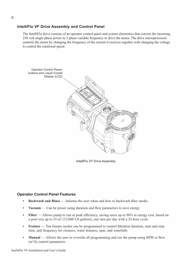
IntelliFlo VF Drive Assembly and Control Panel
The IntelliFlo drive consists of an operator control panel and system electronics that convert the incoming 230 volt single phase power to 3 phase variable frequency to drive the motor. The drive microprocessor controls the motor by changing the frequency of the current it receives together with changing the voltage to control the rotational speed.
Operator Control Panel Features• Backwash and Rinse — Informs the user when and how to backwash filter media
• Vacuum — Can be preset using duration and flow parameters to save energy
• Filter — Allows pump to run at peak efficiency, saving users up to 90% in energy cost, based on a pool size up to 55 m3 (15,000 US gallons), one turn per day with a 24 hour cycle
• Feature — Ten feature modes can be programmed to control filtration duration, start and stop time, and frequency for cleaners, water features, spas, and waterfalls
• Manual — Allows the user to override all programming and run the pump using RPM or flow (m3/h) control parameters
Operator Control Panel, buttons and Liquid Crystal
Display (LCD)
IntelliFlo VF Drive Assembly

10
IntelliFlo VF Installation and User’s Guide
Section 2Operator Control Panel
This section describes the operator control panel controls and LEDs.
IntelliFlo Operator Control Panel
Controls and LEDs1 Filter button/LED: Starts Filter mode. The LED is on when Filter mode is active.
2 Vacuum button/LED: Starts Vacuum mode. The LED is on when Vacuum mode is active.
3 Backwash button/LED: Starts Backwash mode. The LED is on when Backwash mode is active.
4 Manual button/LED: Starts Manual mode. The LED is on when Manual mode is active.
5 Select button: Displays available menu items or enters edit mode for changing a value on line two of the display.
6 Escape button: Moves to next level up in the menu structure, and/or stops editing the current setting.
7 Menu button: Accesses the menu items if the pump is stopped.
8 Enter button: Saves current menu item setting. Press this button to acknowledge alarms and warning alerts.
FILTER 12:15
15.WPOWERRUNNING
1
5
2
6
8
4
3
7
®

11
IntelliFlo VF Installation and User’s Guide
Controls and LEDs (Continued)
9 Arrow buttons: • Up arrow: Move one level up in the menu tree or increase a digit when editing a setting.• Down arrow: Move one level down in the menu tree or decrease a digit when editing a setting.• Left arrow: Move cursor left one digit when editing a setting.• Right arrow: Move cursor right one digit when editing a setting.
10 Feature 1 button: Starts Feature 1 mode. The LED is lit when mode is active. 11 Feature 2 button: Starts Feature 2 mode. The LED is lit when mode is active. 12 Start/Stop button: Start or Stop the pump. When the LED is lit it indicates that the pump is currently running or in a
mode to start automatically. 13 Reset button: Reset alarm or alert.
LEDs On: This green, power LED is on when IntelliFlo is powered on. Warning: This LED is on if a warning condition is present. Alarm: This LED is on if an alarm condition has occurred. Control Panel LCD Display LCD Display Lines:
• Line 1 - Mode and time • Line 2 - Data• Line 3 - Name of data in line 2• Line 4 - Run status
FILTER 12:15
15.WPOWERRUNNING
10
11
15
149
13
12
Line 1
Line 2
Line 3Line 4
®
{14
15

12
IntelliFlo VF Installation and User’s Guide
Priming Setup ExampleThe following example illustrates the steps to set up Priming Mode. The control panel buttons are pictured below to help you become familiar with their appearance and function.
To set up the Priming Mode flow rate and time:
1. Be sure that the green power LED is on and the pump is stopped. If the pump is running, press the Start/Stop button to stop it.
2. Press the Menu button. “Pool Data” is displayed.
3. Press the Down arrow to scroll to the “Priming” menu item.
4. Press the Select button to select the “Priming” menu item. “Max Priming Flow” is displayed. Press the Select button to select it.
5. To change the Max Priming Flow setting, press the Left and Right arrows to select which digit to modify.
• Press the Up and Down arrows to change the selected digit.
6. When the desired value is displayed, press the Enter button to save the changes.
• Press the Escape button to exit edit mode without saving.
7. Use the Up and Down arrows to scroll to “Max Priming Time” or “System Priming Time.” Press the Select button to select it.
8. To change the Max Priming Time setting, press the Left and Right arrows to select which digit to modify.
• Press the Up and Down arrows to change the selected digit.
9. When the desired value is displayed, press the Enter button to save the changes.
• Press the Escape button to exit edit mode without saving.
3X
PrimingMENU 14:09
13 m³/hPriming
Max Priming Flow
14:09
MENU
Pool Data14:09
0013 m³/hPriming
Max Priming Flow
14:09
0013 m³/hPriming
Max Priming Flow
14:09
0023 m³/hPriming
Max Priming Flow
14:09
0023 m³/hPriming
Max Priming Flow
14:09
0020 m³/hPriming
Max Priming Flow
14:09
20 m³/hPriming
Max Priming Flow
14:09
15. MINPriming
Max Priming Time
14:09
0. MINPriming
System Priming Time
14:09
PrimingMENU 14:09
Priming Setup

13
IntelliFlo VF Installation and User’s Guide
Section 3Operating IntelliFlo VF
This section describes how to use the IntelliFlo VF operator control panel to set up the pump’s operating modes.
IntelliFlo Operating Modes: The operating mode buttons are Manual Mode, Filter Mode, Backwash Mode, Vacuum Mode, Feature 1, and Feature 2. Feature 3 through 9 are set up in the Features settings menu. For more information on Feature 3-9, see “Feature 3-9” on page 34, and “Feature 3-9 Setup” on page 39.
External Control Mode is activated and operated through the IntelliComm communication center. See “External Control Mode” on page 20 for more information on operating the IntelliFlo by remote control.
IntelliFlo Menu Button: Use the Menu button to access the settings for the above modes. See page 21 for more information on the Menu button.
Operating Modes
Note: If the pool system uses a filter, always monitor pressure at the filter when changing the speed (RPM) or flow (m3/h) from IntelliFlo.
Manual Mode
Metering the System
The first step in programming and operating the IntelliFlo is to determine the flow rates for the various devices and features in your pool system that require flow. Because each pool system is unique, devices that operate at a given flow rate in one system may not function optimally at that same flow rate in another system.
Menu Button(to acces mode settings) (page 21)
Vacuum Mode (page 18)Filter Mode (page 19)
Backwash Mode (page 17)Manual Mode (page 13)
Feature 2 (page 34)Feature 1 (page 34)
FILTER 12:15
15.WPOWERRUNNING
®

14
IntelliFlo VF Installation and User’s Guide
MANUAL RPM
15.W12:15
POWERRUNNING
MANUAL RPM
1000.RPM12:15
ACTUAL.SPEEDRUNNING
MANUAL RPM
0 m³/h12:15
FLOWRUNNING
MANUAL RPM
1000.RPM12:15
Set SPEEDRUNNING
MANUAL RPM
12m³/h12:15
Set FLOWRUNNING
® ® ® ® ®
Use Manual Mode to meaure and test the requirements of each flow-operated device in your pool system, and record your results for later setup in the IntelliFlo’s menus. See “Menus” on page 21 for detailed instructions.
To operate IntelliFlo in manual mode:
Manual RPM Mode
1. Ensure that the green power LED is on.
2. Press the Manual button. Press the Start/Stop button. “MANUAL RPM” will appear in the top left corner of the display, indicating that the pump is in Manual RPM Mode.
3. Use the Up and Down arrow buttons to view the screens below:
• POWER (Watts): Displays power to the motor shaft in continuous watts• ACTUAL SPEED (RPM): Displays pump speed in RPM • FLOW (m3/h): Displays commanded flow. Will read “0” unless a value is programmed in
the “Set FLOW” screen (See “To Change the Speed and Flow” on the following page.). As long as the IntelliFlo is in MANUAL RPM Mode, the programmed, or “commanded”, flow —not the actual flow—will appear in the Flow screen. To view the actual flow, switch from Manual RPM Mode to Manual Flow Mode (See “Manual Flow Mode” on the following page.).
• Set SPEED (RPM): Allows you to set IntelliFlo to run at a continuous pump speed• Set FLOW (m3/h): Allows you to set IntelliFlo in Manual Flow Mode to allow the pump
to change speed to manage the flow rate based on system changes

15
IntelliFlo VF Installation and User’s Guide
Manual Mode (Continued)
Manual Flow Mode
4. Press the Start/Stop button to stop the pump. Use the Up and Down arrow buttons to scroll to the “Set FLOW” menu item. Press the Select button to select it.
5. To change the setting, press the Left and Right arrows to select which digit to modify, then use the Up and Down arrows to change the selected digit.
6. When you are done, press the Enter button to save the changes. To cancel any changes, press the Escape button to exit edit mode without saving.
7. Press the Start/Stop button. If you pressed the Enter button in step 6, “MANUAL FLOW” will appear in the top left corner of the display, indicating that the pump is now in Manual Flow Mode.
8. Use the Up and Down arrow buttons to view the screens below:
• POWER (Watts): Displays power to the motor shaft in continuous watts• ACTUAL SPEED (RPM): Displays pump speed in RPM • FLOW (m3/h): Displays actual flow as long as the IntelliFlo is in Manual Flow Mode.• Set SPEED (RPM): Allows you to set IntelliFlo to run at a continuous pump speed• Set FLOW (m3/h): Allows you to set IntelliFlo in Manual Flow Mode to allow the pump
to change speed to manage the flow rate based on system changes
Note: IntelliFlo’s sensors—with the exception of the flow sensor— will not work in Manual Mode, so warning alarms, such as the Suction Blockage alarm, will not operate.
To adjust the Speed and Flow:
1. Be sure that the green power LED is on.
2. Press the Manual button (LED on).
3. a) To set the speed: Use the Up and Down arrow button to scroll to the “Set SPEED” screen. Press the Select button to select it. The flow values can be set from 4 to 29 m3 per hour (default 12m3/h). To change the setting, see step 4 below.
MANUAL FLOW
15.W12:15
POWERRUNNING
MANUAL FLOW
1700.RPM12:15
ACTUAL.SPEEDRUNNING
MANUAL FLOW
14m³/h12:15
FLOWRUNNING
MANUAL FLOW
1000.RPM12:15
Set SPEEDRUNNING
MANUAL FLOW
14m³/h12:15
Set FLOWRUNNING
® ®® ® ®
16
IntelliFlo VF Installation and User’s Guide
Manual Mode (Continued)
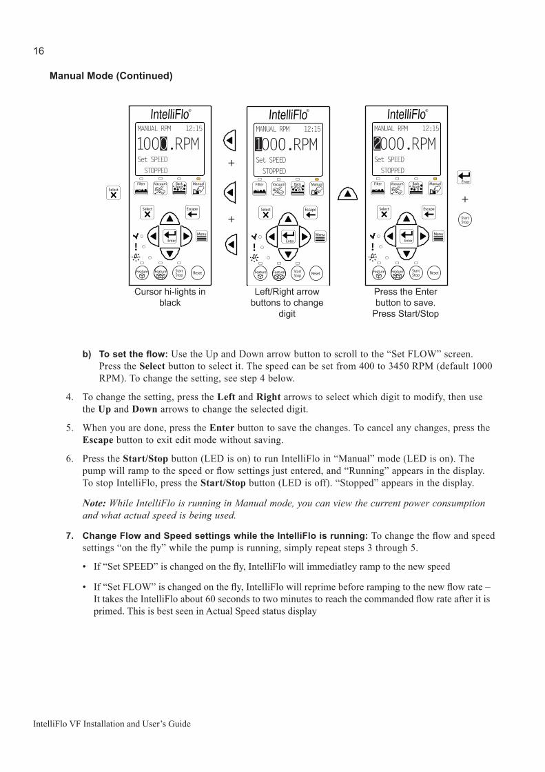
b) Tosettheflow: Use the Up and Down arrow button to scroll to the “Set FLOW” screen. Press the Select button to select it. The speed can be set from 400 to 3450 RPM (default 1000 RPM). To change the setting, see step 4 below.
4. To change the setting, press the Left and Right arrows to select which digit to modify, then use the Up and Down arrows to change the selected digit.
5. When you are done, press the Enter button to save the changes. To cancel any changes, press the Escape button to exit edit mode without saving.
6. Press the Start/Stop button (LED is on) to run IntelliFlo in “Manual” mode (LED is on). The pump will ramp to the speed or flow settings just entered, and “Running” appears in the display. To stop IntelliFlo, press the Start/Stop button (LED is off). “Stopped” appears in the display.
Note: While IntelliFlo is running in Manual mode, you can view the current power consumption and what actual speed is being used.
7. Change Flow and Speed settings while the IntelliFlo is running: To change the flow and speed settings “on the fly” while the pump is running, simply repeat steps 3 through 5.
• If “Set SPEED” is changed on the fly, IntelliFlo will immediatley ramp to the new speed
• If “Set FLOW” is changed on the fly, IntelliFlo will reprime before ramping to the new flow rate – It takes the IntelliFlo about 60 seconds to two minutes to reach the commanded flow rate after it is primed. This is best seen in Actual Speed status display
1000.RPMMANUAL RPM 12:15
Set SPEEDSTOPPED
2000.RPMMANUAL RPM 12:15
Set SPEEDSTOPPED
1000.RPMMANUAL RPM 12:15
Set SPEEDSTOPPED
+
+
+
® ® ®
Press the Enter button to save.
Press Start/Stop
Cursor hi-lights in black
Left/Right arrow buttons to change
digit

17
IntelliFlo VF Installation and User’s Guide
BACKWASH 12:15
5.MINBW REMAININNG TIME
RUNNING
®
BACKWASH 12:15
0.WPOWERRUNNING
®
BACKWASH 12:15
0.RPMACTUAL SPEEDSTOPPED
®
BACKWASH 12:15
13 m³/hFLOWRUNNING
®
Backwash Mode
When the pool filter’s internal pressure reaches “Clean Filter Pressure,” IntelliFlo displays a “Service System Soon” alert on the control panel display (See “To set the Clean Filter Pressure” on page 26 and “Clean Fiter Pressure Example” on page 30.), indicating that the filter needs to be cleaned, or “backwashed.”
• Backwashing is essential for cleaning and maintaining the “% Clean Filter” menu (See “Filter Mode” on page 19 for more information on filters.).
• Upon completing the backwashing cycle, IntelliFlo recalculates the clean filter pressure and starts a new cycle
• The Backwash button operates both backwash and rinse portions of the backwashing cycle• For cartridge filters, a backwashing cycle must be performed when cleaning or replacing filters.
IntelliFlo then resets the “Clean Filter Pressure” level• If you are charging a DE system, first charge the system during a normal running cycle. Once the
filter is charged, run the pump in backwash mode with the filter valve in the filter position to reset the % clean filter status. Then run the pump in filter mode.
Note: IntelliFlo will ramp up to full speed if necessary to achieve the commanded flow. Be sure that the system can withstand the resultant pressures.
A complete backwashing cycle includes a “backwash” phase and a “rinse” phase, and is accomplished in Backwash Mode. At a press of the Backwash button, IntelliFlo will run in this mode at the flow rate and for the length of time you programmed in the Backwash menu. At the end of this specified duration, IntelliFlo will stop to give you the opportunity to reposition the filter valve to “Rinse” before beginning a rinse cycle to complete the filter cleaning process. The backwash flow rate, backwash duration, and rinse duration are programmed in the Backwash settings men. See “Backwash Setup” on page 45 for more infomation on Backwash Mode setup. To operate Backwash Mode:
1. Ensure that the green power LED is on.
2. Press the Backwash button (LED is on). Press the Start/Stop button. IntelliFlo is now in Backwash Mode and will operate at the flow rate and for the duration of time specified in the Backwash settings menu.
3. The control panel screen in Backwash Mode will display a countdown of the time remaining in the programmed duration of that function. By using the Up and Down arrow buttons, you can switch between screens displaying the power usage in Watts (W), pump speed in RPM, and flow rate.

18
IntelliFlo VF Installation and User’s Guide
Backwash Mode (Continued)
4. When Backwash Mode is stopped, manually or upon completion of the preset backwash cycle, the IntelliFlo will stop, and the control panel will display “Rinse” in the top left corner. IntelliFlo will not begin the rinse cycle until you press the Start/Stop button. First, reposition the backwash valve on the filter to “Rinse,” then press the Start Stop button. IntelliFlo will begin the rinse portion of the backwash cycle. The flow rate for the rinse cycle is the same as the rate specified for the backwash cycle. IntelliFlo will run at this rate for the length of time specified in the “Rinse Duration” setting of the Backwash settings menu.
5. Once IntelliFlo has completed the backwash and rinse cycles, it will reset the Filter Status to 0%, indicating that the internal filter pressure is now at 0% of the Clean Fiter Pressure you set in the Filter setup menu (See “To set the Clean Filter Pressure” on page 26.).
6. Upon completion of the backwashing and rinse cycles, the backwash valve on the filter should be returned to the “Filter” position.
Vacuum Mode
Vacuum Mode is intended exclusively for manual pool cleaning, and, like Feature 1(2), is designed for “on demand” operation. The Vacuum settings menu is used to set the parameters for VacuumMode. Flow rate and duration are the only parameters available in Vacuum Mode. See “Vacuum Mode Setup” on page 46 for more information on setting up Vacuum Mode.
CAUTION: Since manual pool cleaning requires the physical presence of an individual to perform the task, the “Blocked System” alert, and other automatic warnings are disabled while IntelliFlo is in Vacuum Mode. Automatic pool cleaners, (e.g. Kreepy Krauly, PoolShark) should not be operated in Vacuum mode.
To operate Vacuum Mode:
1. Ensure that the green power LED is on.
2. Press the Vacuum button. Press the Start/Stop button. “VACUUM” will appear in the top left corner of the display, indicating that the pump is in Vacuum Mode.
RINSE 12:15
1.MINRINSE REMAINING TIME
RUNNING
®

19
IntelliFlo VF Installation and User’s Guide
Vacuum Mode (Continued)
3. Use the Up and Down arrow buttons to view the screens below:
• REMAINING TIME: Displays time remaining in programmed duration• POWER (Watts): Displays power to the motor shaft in continuous watts• ACTUAL SPEED (RPM): Displays pump speed in RPM • FLOW (m3/h): Displays flow
Filter Mode
IntelliFlo uses Filter Mode to perform the routine circulation of water through the pool’s filter. At a press of the Filter button, IntelliFlo will calculate the flow rate necessary to achieve the desired rate of turnover, based on the parameters entered for Filter Mode in the Filter Settings Menu, and will control the pump speed to maintain constant flow during that period. See “Filter Settings Menu” on page 26 for more detailed information on Filter Mode setup.
1. Ensure that the green power LED is on.
2. Press the Filter button. Press the Start/Stop button. “FILTER” will appear in the top left corner of the display, indicating that the pump is in Filter Mode.
3. Use the Up and Down arrow buttons to view the screens below:
• POWER (Watts): Displays power to the motor shaft in continuous watts• ACTUAL SPEED (RPM): Displays pump speed in RPM • FLOW (m3/h): Displays flow• Filter Status OK (%): Displays, in percent, the degree to which the internal pressure
of the pool filter is approaching “Clean Filter Pressure.” See “To set the Clean Filter Pressure” on page 26, and “Clean Filter Pressure Example” on page 30 for more information on Clean Filter Pressure.
FILTER
15.W12:15
POWERRUNNING
FILTER
1560.RPM12:15
ACTUAL.SPEEDRUNNING
FILTER
14m³/h12:15
FLOWRUNNING
FILTER
62.0%12:15
Filter Status OKRUNNING
VACUUM
1.MIN12:15
REMAINING TIMERUNNING
VACUUM
23.W12:15
POWERRUNNING
VACUUM
1545.RPM12:15
ACTUAL SPEEDRUNNING
VACUUM
16m³/h12:15
FLOWRUNNING
® ® ®®

20
IntelliFlo VF Installation and User’s Guide
Feature 1(2) Mode
Feature 1 and Feature 2 should be used to operate water features such as spas, automatic pool cleaners, and waterfalls. At a press of the Feature 1 or Feature 2 button, IntelliFlo will run in this mode at the flow rate and for the length of time programmed in the Vacuum Settings Menu. See “Feature 1 and 2” on page 34 and “Feature 1 or 2 Setup” on page 38 for more information on setting up Feature 1(2).
Once the Flow and Duration parameters for Feature 1(2) have been programmed in the Features 1(2) settings menu, the operation of these features is controlled through the Feature 1 and Feature 2 buttons.
1. Press the Feature 1 or Feature 2 button, then press the Start/Stop button. IntelliFlo will activate the feature, and the active feature LED will be lit until the feature has finished operation.
2. The “Feature 1” screen will display a countdown of the time remaining in the duration you programmed for that feature. By using the Up and Down arrow buttons, you can switch between screens displaying current flow, power usage in Watts (W), and pump speed in RPM.
The example below, shows Feature 1 activated with the flow setting of 12m3/h, and the time duration setting of 1 minute (0:01)
External Control Mode
IntelliFlo With IntelliComm Communication Center
The IntelliFlo can be connected to the Pentair IntelliComm Communication Center via an optional communications cable (P/N 350122). The IntelliComm is equipped with four pairs of input terminal connections which can be connected to IntelliFlo’s Program 1(4) in the External Control menu (See page 44 for more information on setting up External Control.). Each of Program 1(4) is equipped with a “Set Flow” setting for programming IntelliFlo’s flow rate for that program. IntelliComm’s input terminal connections are actuated by 15 - 240 VAC or 15 - 100 VDC received from another device, usually a pool heating system, prompting IntelliComm to send a serial command activating Program 1(4). The IntelliFlo will then maintain the flow rate set for Program 1 until it receives a subsequent command, either via the IntelliComm, or manually through the control panel.
®
Feature 1 12:15
12m³/hSet Flow
Feature 1 12:15
0:01Time Duration
®
Feature 1 with flow settings of 12m3/h, and time duration setting of 1 minute programmed in “Feature 1 and 2” menu. See page 34.
LEDs lit
®
FEATURE 1 5:01
1.MINREMAINING TIMERUNNING
Time remaining in minutesPump status: runningFEATURE 1 IN
OPERATION
Feature 1 pressed
Start/Stop pressed
LEDs lit

21
IntelliFlo VF Installation and User’s Guide
External Control Mode (Continued)
Additionally, Programs 1(4) are equipped with a “Time Delay Stop” setting which allows you to specify a period of time for which IntelliFlo will continue to operate at the programmed flow rate after the voltage has stopped. See “External Control Setup with IntelliComm” on page 44 for more information on setting up IntelliComm.
If more than one input on the IntelliComm is active, IntelliComm will communicate the highest number to the IntelliFlo pump. The IntelliComm will always communicate to pump address 1.
Note: The IntelliFlo control panel remains active when the IntelliFlo is connected to the IntelliComm.The following table shows the wiring terminal descriptions for IntelliComm.
Terminal number Terminal name Voltage Maximum
current Phase type Frequency
1-2 Power supply 100 - 240 VAC 100 mA 1 Input 50/60 Hz
3-4 Program 1 15 -240 VAC or 15 - 100 VDC 1 mA* 1 Input 50/60 Hz
5-6 Program 2 15 -240 VAC or 15 - 100 VDC 1 mA* 1 Input 50/60 Hz
7-8 Program 3 15 -240 VAC or 15 - 100 VDC 1 mA* 1 Input 50/60 Hz
9-10 Program 415 -240 VAC or 15 - 100 VDC
1 mA* 1 Input 50/60 Hz
1112
RS-485 + Data: Yellow - Data: Green
-5 to +5 VDC 5 mA 1 Output N/A
Ground
Menu ButtonUse Intelliflo’s menus to configure and set parameters for IntelliFlo’s modes.
To access the IntelliFlo Menus:
1) Ensure that the pump is stopped.2) Press the Menu button. “Pool Data” is displayed.3) Use the Up or Down arrow button to scroll through the menu items. Use the Select button to select
a menu item. Press the Enter button to save a setting. Press the Escape button to exit the menu item without saving the changes.
The IntelliFlo menus structure is shown on the following page.
Terminals

22
IntelliFlo VF Installation and User’s Guide
IntelliFlo Menus
POOL DATA Language
Press MENU button to access menusMAIN SCREEN
Pool Volume (4 - 3785m3)
(page 21)
(1 - 16) [Note: 1-8 when connected to IntelliTouch]Pump Address
PRIMING Max Priming Flow (7 - 36m3)
(1 - 15 min.) Max Priming Time
Sys Priming Time (0 - 5 min.)
(page 22)
TIME / CONTR Set Time (hr:min - AM/PM)
Contrast Level (0 - 9)(page 31)
(20° - 40°C) Water Temp
UNITS Flow Unit (m3/h or US GPM)
Time Unit (24h or AM/PM)
Temperature Unit (°C or °F)
(page 22)
FILTER (69 - 3448 mbar)
Cycles per Day (1 - 4 counts)
(hr:mm) Start Cycle 1
Stop Cycle 1
Start Cycle 2
Stop Cycle 2
Start Cycle 3
Stop Cycle 3
Start Cycle 4
Stop Cycle 4
(1 - 8 counts)
Clean Filter Pressure
Turnovers per Day
(hr:mm)
(hr:mm)
(hr:mm)
(hr:mm)
(hr:mm)
(hr:mm)
(hr:mm)
(page 24)
FEATURES Set Flow (4 - 29m3/h)Features 1
Features 2
Features 3
Features 4
Features 5
Time Duration (0:01 - 10:00)
Set Flow (4 - 29m3/h)
Time Duration (0:01 - 10:00)
Set Flow (4 - 29m3/h)
Set Start Time (hr:mm) Set Stop Time (hr:mm)
Activation (Disabled/Enabled)
Set Flow (4 - 29m3/h)
Set Start Time (hr:mm) Set Stop Time (hr:mm)
Activation (Disabled/Enabled)
Set Flow (4 - 29m3/h)
Set Start Time (hr:mm) Set Stop Time (hr:mm)
Activation (Disabled/Enabled)
Features 6
Features 7
Set Flow (4 - 29m3/h)
Set Start Time (hr:mm) Set Stop Time (hr:mm)
Activation (Disabled/Enabled)
Set Flow (4 - 29m3/h)
Set Start Time (hr:mm) Set Stop Time (hr:mm)
Activation (Disabled/Enabled)
Features 8
Features 9
Set Flow (4 - 29m3/h)
Set Start Time (hr:mm) Set Stop Time (hr:mm)
Activation (Disabled/Enabled)
Set Flow (4 - 29m3/h)
Set Start Time (hr:mm) Set Stop Time (hr:mm)
Activation (Disabled/Enabled)
Set Flow (4 - 29m3/h)
Set Run Time (0:01 - 00:59) Set Interval Time (0:02 - 4:15)
Activation (Disabled/Enabled)
(page 32)
M.O. Flow
EXT. CONTROL Activation (Enabled/Disabled)Program 1
Program 2
Program 3
Program 4
Set Flow (4 - 29m3/h) / Time Delay Stop (hr:mm) (0:00 - 0:10)
Activation (Enabled/Disabled) (15 - 130 gpm) Set Flow (4 - 29m
3/h) / Time Delay Stop (hr:mm) (0:00 - 0:10)
Set Flow (4 - 29m3/h) / Time Delay Stop (hr:mm) (0:00 - 0:10)
Activation (Enabled/Disabled)
Activation (Enabled/Disabled)
(page 42)
Set Flow (4 - 29m3/h) / Time Delay Stop (hr:mm) (0:00 - 0:10)
VACUUM (4 - 29m3/h)Vacuum Flow
Vacuum Duration (0:01 - 10:00) (page 45)
Feature Linked (1 - 9) Set Max Speed (450 - 3450 RPM) Set Min Speed (400 - 3400 RPM)
Activation (Disabled/Enabled) Wave
Period (10 - 300 SEC)
Feature Linked (1 - 9) Set Max Speed (450 - 3450 RPM) Set Min Speed (400 - 3400 RPM)
Activation (Disabled/Enabled) Pulse
Period (2 - 300 SEC)
BACKWASH (4 - 29m3/h)Backwash Flow
(page 44)
(0:01 - 1:00) Rinse Duration
Backwash Duration (0:01 - 1:00)
23
IntelliFlo VF Installation and User’s Guide
Pool Data Menu
Use the Pool Data menu to configure IntelliFlo for the pool and spa system. From this menu you can set the language of the control panel LCD, enter an address for the IntelliFlo pump when connected to an IntelliTouch system, enter the volume of pool water in cubic meters (m3), and enter an estimate of the pool water temperature.
To access the Pool Data menu:
1. Ensure that the green power LED is on and the pump is stopped.2. Press the Menu button. “Pool Data” is displayed.3. Press the Select button to select it.
a) To choose the language in which information is displayed in the Control Panel: Use the Up and Down arrow buttons to scroll to the “Language” setting (Default ENGLISH). Press the Select button to select it. Use the Up and Down arrows to scroll through the six available languages (ENGLISH, DEUTSCH, FRANÇAIS, ESPAÑOL, ITALIANO, NEDERLANDS). Press the Enter button to select one of the languages.
b) To enter the pump address: Use the Up and Down arrow buttons to scroll to the “Pump Address” setting. Press the Select button to select it. To change the setting, press the Left and Right arrows to select which digit to modify, then use the Up and Down arrows to change the selected digit.When you are done, press the Enter button to save the changes. To cancel any changes, press the Escape button to exit edit mode without saving.
c) To enter the pump volume (pool size): Use the Up and Down arrow buttons to scroll to the “Pool Volume” setting. Press the Select button to select it. To change the setting, press the Left and Right arrows to select which digit to modify, then use the Up and Down arrows to change the selected digit. When you are done, press the Enter button to save the changes. To cancel any changes, press the Escape button to exit edit mode without saving.
Enter the estimated volume of the pool expressed in cubic meters (m3). IntelliFlo can accept a value for pool volume from 4 to 3785m3 (Default 117 m3). The closer the estimated volume to the actual pool volume, the more accurately IntelliFlo will perform turnovers in Filter Mode. IntelliFlo uses this value, in conjunction with parameters entered in the Filter Settings menu, to determine turnover and flow rates, and to time cycles in Filter Mode.
MENU 12:15
Pool Data
®
®
Pool Data
Language
12:15
ENGLISH
Pool Data
Pump Address
12:15
1
®
Pool Data
Pool Volume
12:15
117.m³
®

24
IntelliFlo VF Installation and User’s Guide
Pool Data Menu (Continued)
d) To enter the water temperature: Use the Up and Down arrow buttons to scroll to the “Water Temperature” setting. Press the Select button to select it. To change the setting, press the Left and Right arrows to select which digit to modify, then use the Up and Down arrows to change the selected digit. When you are done, press the Enter button to save the changes. To cancel any changes, press the Escape button to exit edit mode without saving.
Enter the current water temperature from 20°C - 40°C (Default 24°C). Strict temperature accuracy is not critical since the water temperature value is used only to enhance the accuracy of the flow sensor, however a close estimate is desirable. Similarly, when the IntelliFlo is connected to an IntelliTouch system, water and air temperature information is provided by the system sensors. The more accurate the entered temperature, the more accurate the flow reading will be on the IntelliFlo control panel LCD while it is running.
Units Menu
Use the Units menu to set the unit in which IntelliFlo will display data in the Control Panel. IntelliFlo allows you to choose a unit for flow rate, time, and temperature.
To access the Units menu:
1. Ensure that the green power LED is on.2. Press the Menu button. “Pool Data” is displayed.3. Use the Up and Down arrow buttons to find the “Units” menu item. Press the Select button to select it.
a) To choose the Flow Unit: Use the Up and Down arrow buttons to scroll to the “Flow Unit” setting. Press the Select button to select it. Use the Up and Down arrow buttons to choose between cubic meters (m3/h), or gallons per minute (US GPM), then press Enter to select the choice.
b) To choose the Time Unit: Use the Up and Down arrow buttons to scroll to the “Time” setting. Press the Select button to select it. Use the Up and Down arrow buttons to choose between a 24-hour time clock, or AM/PM, then press Enter to select the choice.
c) To choose the Temperature Unit: Use the Up and Down arrow buttons to scroll to the “Temperature Unit” setting. Press the Select button to select it. Use the Up and Down arrow buttons to choose between Celsius (°C), or Fahrenheit (°F), then press Enter to select the choice.
Priming Menu
To “prime” a pump means filling the pump and suction pipe with water. This process evacuates the air from all the suction lines and the pump. It may take several minutes to prime depending on the depth of water, pipe size and length. Water cannot fill the pipes to achieve prime unless the air first escapes, and it is easier to prime a pump if the pool’s piping system contains outlets for the air to escape. Pumps do not hold prime; the pool’s piping system has that task.
Priming is a function used every time the motor is started with a flow as reference. The “Priming Flow” function ensures the proper operation of the pump. The “System Priming Time” function ensures proper operation of the whole pool system.
Pool Data
Water Temperature
12:15
24 °C
®
25
IntelliFlo VF Installation and User’s Guide
Priming Menu (Continued)
When the pump is priming, the control panel LCD displays “Priming” and then, for a moment, displays “Primed” when priming is complete.
CAUTION: To avoid permanent damage to the IntelliFlo pump, before starting the system, fill the IntelliFlo housing strainer with water so that the pump will prime correctly. If there is no water in the strainer the pump will not prime.
To access the Priming menu:
1. Ensure that the green power LED is on and the pump is stopped.2. Press the Menu button. “Pool Data” is displayed.3. Use the Up and Down arrow buttons to find the “Priming” menu item. Press the
Select button to select it.
a) To set the Max Priming Flow (m3/h): Use the Up and Down arrow buttons to scroll to the “Max Priming Flow” setting. Press the Select button to select it. To enter the maximum flow range (m3/h) during the priming cycle, see step 4.
The “Max Priming Flow” value is entered as cubic meters (m3/h), from 7 to 36 m3/h (Default 13 m3/h). The “Max Priming Flow” is a critical parameter for the pool and equipment. Each time the pump starts, this parameter will determine the maximum flow of the pump. If the flow is too high, equipment damage can occur. If the flow is to low the pump will not prime. This “flow” is system dependent and may require iteration. During priming, the flow will never exceed the maximum priming flow value set in this step, however, it is common for the pump to ramp up and down quickly while priming. Always maintain as low a flow rate as possible for cost savings and safety.
b) To set the Max Priming Time: Use the Up and Down arrow buttons to scroll to the “Max Priming Time” setting. Press the Select button to select it. To enter the maximum time for priming before “PRIMING ERROR”, see step 4.
The “Max Priming Time” value is entered in minutes, from 1 to 15 minutes. The default is 15 minutes. Use this parameter to set the length of time you would like for IntelliFlo to continue to try to prime before it reports an error. Remember that the IntelliFlo will attain prime every time it starts and goes through this cycle. The IntelliFlo mechanical seal can withstand about 15 minutes before severe damage occurs. You can set this range between 1and 15 minutes. The lower you set the time, the sooner a priming error will occur if the system is experiencing difficulty priming. A well plumbed pool should prime in under 30 seconds without removal of the strainer. If the strainer has been removed for cleaning and a substantial amount of air is in the system, the pool should prime in approximately 60 to 90 seconds. Priming time will vary.
MENU 12:15
Priming
®
Priming 12:15
17 m3/hMax Priming Flow
®
Priming 12:15
15. MINMax Priming Time
®
26
IntelliFlo VF Installation and User’s Guide
Priming Menu (Continued)
c) To set the System Priming Time: Use the Up and Down arrow buttons to scroll to the “System Priming Time” setting. Press the Select button to select it. To enter additional priming time to ensure that the entire system is fully primed, see step 4.
Any additional time required for the pool piping system to reach prime after the pump is primed is called “System Priming Time.” The “System Priming Time” value is entered in minutes, from 0 to 5 minutes. (Default 0 minutes). Remember that the average system should prime quickly, and that IntelliFlo has the ability to monitor itself to ensure that it is primed. “System Priming Time” is for high volume, or complex systems that may need additional priming time to relieve all the air from the pipes. The builder can program a pre-determined amount of time, up to 5 minutes, to aid in relieving the air from difficult filters or complex vertical plumbing. The “System Priming Time” should only be used where large air traps become problems within the system. During the priming cycle at each startup, the display will inform the user when System Priming is engaged and when it is finished .
4. To change the setting, press the Left and Right arrows to select which digit to modify, then use the Up and Down arrows to change the selected digit.
5. When you are done, press the Enter button to save the changes. To cancel any changes, press the Escape button to exit edit mode without saving.
Filter Menu
IntelliFlo will calculate the required flow rate based on pool size, pool turns per day, cycles per day, and schedule to control the pump motor speed and keep a constant flow. The filter mode can run schedules, cycles, power saves, or features. The IntelliFlo internal scheduler will keep track of which function to run. IntelliFlo is constantly monitoring the filter, when it detects that the system is dirty, it will display an “Alert - Service System Soon” message on the control panel display. The user must then clean the filter by performing a Backwash cycle (See “Backwash Mode” on page 17 and “Backwash Menu on page 45 for more information on backwashing).
To access the Filter menu:
1. Ensure that the green power LED is on and the pump is stopped.2. Press the Menu button. “Pool Data” is displayed.3. Use the Up and Down arrow buttons to find the“Filter” menu item. Press the Select button to
select it.
a) To set the Clean Filter Pressure: Use the Up and Down arrow buttons to find the “Clean Filter Pressure” setting. Press the Select button to select it. To change the setting, see step 4 below.
This parameter can be set from 0,1 to 3,5 bar. (Default 1,0 bar). The typical setting for most pools and filters is between 0,6 bar and 0,7 bar.
Priming 12:15
0. MINSystem Priming Time
®
MENU 12:15
Filter
®

27
IntelliFlo VF Installation and User’s Guide
Filter 12:15
965.mbarClean Filter Pressure
®
Filter 12:15
1Turnovers Per Day
®
Filter 12:15
1Cycles Per Day
®
Filter Menu (Continued)
The value entered for the “Clean Filter Pressure” sets how far above “starting pressure” the internal pressure of the filter must climb before the IntelliFlo displays a “Service System Soon” alert. The “starting pressure” is the filter pressure reading at the completion of the last backwashing. Cartridge filters must also be “backwashed” to a clean state to establish this “starting pressure.”
When the IntelliFlo is running in Filter mode, the LCD will display the filter’s cleanliness status (“% Filter Status OK” screen) as a percent of the pressure of a dirty filter as defined above. Once this pressure is reached, the IntelliFlo will display the “Service System Soon” message which notifies the operator that the filter required cleaning. When this alert is active, the IntelliFlo will decrease speed to maintain a constant discharge pressure. The pump flow will then necessarily decrease also until the filter is cleaned. For more information, refer to “Clean Filter Pressure Example” on page 30.
b) To set the number of Turnovers Per Day: Use the Up and Down arrow buttons to find the “Turnovers Per Day” setting. Press the Select button to select it. To change the setting, see step 4 below.
You can set up to eight turns per day (Default 1). It is recommended that one turn per day for energy conservation and requirements be performed for most common residential pools. Refer to sanitizer recommendation for additional information.
c) To set the number of Cycles Per Day: Use the Up and Down arrow buttons to find the “Cycles Per Day” setting. Press the Select button to select it. To change the setting, see step 4 below.
IntelliFlo uses the Cycles Per Day parameter to calculate how much time it has to complete its filter job. You can program up to four (4) start and stop cycles per day (Default 1). See “d) To set the Start and Stop times of Cycles 1 through 4” on the folllowing page. The more time the IntelliFlo is given to operate, the less power and flow will be needed for turning over the pool.
Note: Consumers in certain areas are charged lower energy rates at non-peak hours. To take advantage of this, the IntelliFlo can be programmed to run at any time of the day. The extremely quiet operation of the IntelliFlo makes it feasible to operate during early morning or late at night. The easiest and best way to optimize flow during filter cycles is by adding or subtracting cycle time. This way, the desired flow effect, for example, skimming action, can be achieved while maintaining the desired water turnover rate.
1.0 bar
28
IntelliFlo VF Installation and User’s Guide
Filter Menu (Continued)
d) To set the Start and Stop times of Cycles 1 through 4: Use the Up and Down arrow buttons to find the “Start Cycle 1” setting. Press the Select button to select it. 9:00 is the default setting. Press Enter to set 9:00 as the start time. To change the setting, see step 4 below. Use the Down arrow button to scroll down to the “Stop Cycle 1” setting. Press the Select button to select it. 21:00 is the default setting. Press Enter to set 21:00 as the stop time. To change the setting, see step 4 below.
4. To change the setting, press the Left and Right arrows to select which digit to modify, then use the Up and Down arrows to change the selected digit.
5. When you are done, press the Enter button to save the changes. To cancel any changes, press the Escape button to exit edit mode without saving.
The following example shows the IntelliFlo Control Panel with the Cycle 1 start time programmed for 9:00, and the Cycle 1 stop time programmed for 21:00. The default of one (1) is entered in the “Cycles Per Day” parameter. Note that, as long as one (1) cycle is entered in the “Cycles Per Day” setting, only one of the four available cycles will read “Enabled” on the IntelliFlo Operator Control Panel. See Filter Cycle Settings table on the following page.
On the next example, the IntelliFlo Control Panel shows a Cycle 1 Start time of 8:00 and a Cycle 1 Stop time of 10:00, indicating a cycle of 2 hours. Note that the Cycle 2 (Start time of 10:15) reads “Enabled” because two (2) cycles are entered in the number of Cycles Per Day setting.
Note: IntelliFlo will not allow you to enter overlapping cycle times.
Filter 12:15
1Cycles Per Day
®
Filter 12:15
9:00Start Cycle 1Enabled
®
Filter 12:15
21:00Stop Cycle 1Enabled
®
Cycle 1 Start and Stop time are displayed
Filter 12:15
21:10Start Cycle 2Disabled
®
Cycle 2 Start time is displayed
“Enabled” is displayed because one (1) cycle is selected in the number of Cycles Per Day setting
“Disabled” is displayed because only one (1) cycle is selected in the Cycles Per Day setting. These screens will still display even if they are not enabled.
Filter 12:15
08:00Start Cycle 1Enabled
®
Filter 12:15
10:00Stop Cycle 1Enabled
®
Filter 12:15
10:15Start Cycle 2Enabled
®In this example, the Cycle 1 Start and Stop times are set to run the pump for 2 hours.
Cycle 2 Start time is displayed“Enabled” is displayed because two (2) cycles are selected in the Cycles Per Day setting.
Filter 12:15
2Cycles Per Day
®
29
IntelliFlo VF Installation and User’s Guide
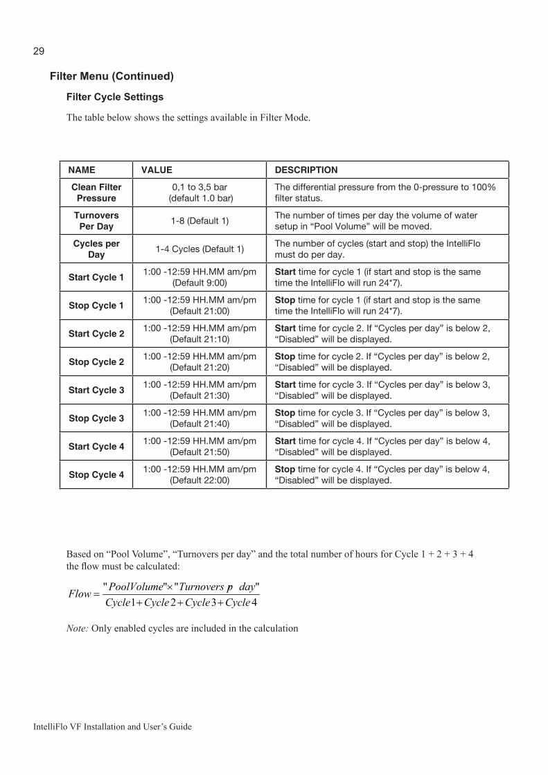
Based on “Pool Volume”, “Turnovers per day” and the total number of hours for Cycle 1 + 2 + 3 + 4 the flow must be calculated:
4321""""
CycleCycleCycleCycledayprTurnoversPoolVolumeFlow
+++×
=
Note: Only enabled cycles are included in the calculation
NAME VALUE DESCRIPTION
Clean Filter Pressure
0,1 to 3,5 bar (default 1.0 bar)
The differential pressure from the 0-pressure to 100% filter status.
Turnovers Per Day 1-8 (Default 1)
The number of times per day the volume of water setup in “Pool Volume” will be moved.
Cycles per Day 1-4 Cycles (Default 1)
The number of cycles (start and stop) the IntelliFlo must do per day.
Start Cycle 1 1:00 -12:59 HH.MM am/pm (Default 9:00)
Start time for cycle 1 (if start and stop is the same time the IntelliFlo will run 24*7).
Stop Cycle 1 1:00 -12:59 HH.MM am/pm (Default 21:00)
Stop time for cycle 1 (if start and stop is the same time the IntelliFlo will run 24*7).
Start Cycle 2 1:00 -12:59 HH.MM am/pm (Default 21:10)
Start time for cycle 2. If “Cycles per day” is below 2, “Disabled” will be displayed.
Stop Cycle 2 1:00 -12:59 HH.MM am/pm (Default 21:20)
Stop time for cycle 2. If “Cycles per day” is below 2, “Disabled” will be displayed.
Start Cycle 3 1:00 -12:59 HH.MM am/pm (Default 21:30)
Start time for cycle 3. If “Cycles per day” is below 3, “Disabled” will be displayed.
Stop Cycle 3 1:00 -12:59 HH.MM am/pm (Default 21:40)
Stop time for cycle 3. If “Cycles per day” is below 3, “Disabled” will be displayed.
Start Cycle 4 1:00 -12:59 HH.MM am/pm (Default 21:50)
Start time for cycle 4. If “Cycles per day” is below 4, “Disabled” will be displayed.
Stop Cycle 4 1:00 -12:59 HH.MM am/pm (Default 22:00)
Stop time for cycle 4. If “Cycles per day” is below 4, “Disabled” will be displayed.
Filter Menu (Continued)
Filter Cycle Settings
The table below shows the settings available in Filter Mode.
30
IntelliFlo VF Installation and User’s Guide
Filter Menu (Continued)
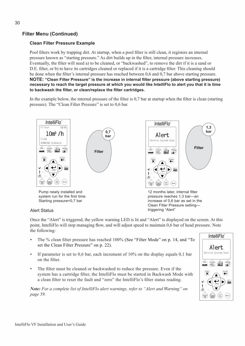
Clean Filter Pressure Example
Pool filters work by trapping dirt. At startup, when a pool filter is still clean, it registers an internal pressure known as “starting pressure.” As dirt builds up in the filter, internal pressure increases. Eventually, the filter will need a) to be cleaned, or “backwashed”, to remove the dirt if it is a sand or D.E. filter, or b) to have its cartridges cleaned or replaced if it is a cartridge filter. This cleaning should be done when the filter’s internal pressure has reached between 0,6 and 0,7 bar above starting pressure. NOTE: “CleanFilterPressure”istheincreaseininternalfilterpressure(abovestartingpressure)necessary to reach the target pressure at which you would like IntelliFlo to alert you that it is time tobackwashthefilter,orclean/replacethefiltercartridges.
In the example below, the internal pressure of the filter is 0,7 bar at startup when the filter is clean (starting pressure). The “Clean Filter Pressure” is set to 0,6 bar.
Alert Status
Once the “Alert” is triggered, the yellow warning LED is lit and “Alert” is displayed on the screen. At this point, IntelliFlo will stop managing flow, and will adjust speed to maintain 0,6 bar of head pressure. Note the following:
• The % clean filter pressure has reached 100% (See “Filter Mode” on p. 14, and “To set the Clean Filter Pressure” on p. 22).
• If parameter is set to 0,6 bar, each increment of 10% on the display equals 0,1 bar on the filter.
• The filter must be cleaned or backwashed to reduce the pressure. Even if the system has a cartridge filter, the IntelliFlo must be started in Backwash Mode with a clean filter to reset the fault and “zero” the IntelliFlo’s filter status reading.
Note: For a complete list of IntelliFlo alert warnings, refer to “Alert and Warning” on page 59.
AlertService System Soon
®
Pump newly installed and system run for the first time. Starting pressure=0,7 bar
12 months later, internal filter pressure reaches 1,3 bar—an increase of 0,6 bar as set in the Clean Filter Pressure setting—triggering “Alert”
10 PSI
Filter
24 PSI
Filter
Filter 12:15
10m³/hRUNNING ScheduleFLOW
®
AlertService System Soon
®
0,7 bar
1,3 bar

31
IntelliFlo VF Installation and User’s Guide
Filter Menu (Continued)
Using Filter Mode in conjunction with Features Mode
IntelliFlo will start and stop at the times you program for filter cycles 1-4, however the parameters you set to operate features in Features Mode (Feature 3-9 only) supercede the filter cycle parameters you set in Filter Mode. As seen in the example below, cycles programmed in Feature 3-9 will override the filter cycles programmed in Filter Mode, however when the feature cycles are completed, IntelliFlo will recalculate the flow rates and durations necessary to complete the interrupted filter cycles, and will resume them at the point where it left off. This may result in a filter cycle finishing early if the volume of water required to complete the cycle is reached early because the pump was running to operate a feature.
Example: Filter Cycle 1 is programmed in Filter Mode for a 80 m3 pool. The cycle is programmed to perform 1 Turnover with a start time of 1:00 and a stop time of 11:00.
InterlliFlo calculates the flow rate to achieve this at 8 m3/h (8 m3/h x 10 hours = 80 m3).
Feature 3 is programmed to start at 4:00 and run at 15 m3/h for 4 hours, stopping at 8:00 (15 m3/h x 4 hours = 60 m3/h).
The filter cycle begins at 1:00, as scheduled, and runs at a rate of 8 m3/h until 4:00. At that time, Feature 3 overrides Filter Cycle 1 and runs until 8:00 at a rate of 15 m3/h.
When Feature 3 stops at 8:00, IntelliFlo has pumped 84 m3 of water (8 m3/h*3 hours + 15 m3/h*4 hours = 84 m3), exceeding the 80 m3 necessary to complete Filter Cycle 1. As a result, IntelliFlo does not resume Filter Cycle 1 and treats it as completed at 8:00, although it was originally scheduled to run until 11:00.
Note: Feature 1 and 2 in Features Mode do not have time-of-day functions and do not affect the filtercycletime(See“Feature1(2)Mode”onpage20,and“Feature1and2”onpage34.). IntelliFlo will not factor in the active time for Feature 1 and 2 in its recalculation of the reduced filter cycle time in the example above.
8 m3/h
15 m3/h
Flow
Time1 84 11
FilterCycle 1
Feature 3

32
IntelliFlo VF Installation and User’s Guide
Filter Menu (Continued)
Flow Control and Filter Mode
The Filter Mode feature enables IntelliFlo to overcome head pressure loss to maintain the required flow. The flow that the unit can provide is limited by the installed plumbing. If more flow is demanded than the IntelliFlo can provide, it will ramp to full speed and create pressure.
The following example shows a ramp as flow increases from 10 to 17 m3/h.
Time
Speed
10 m3/h
Valve is moved
17 m3/h
Ramps in SpeedQuickly
Series of small slow ramps
Power and RPM stabilize and required flow is attained
1
2
3

33
IntelliFlo VF Installation and User’s Guide
Time and Contrast Menu
Use the “Time/Contr” menu to set the IntelliFlo system clock and to adjust the contrast of the control panel display. The IntelliFlo system clock controls all scheduled start and stop times, functions, and programmed cycles. The system clock can store the correct time for up to 96 hours after power is shut off. After 96 hours, the clock must be reset to the correct time.
Setting System Time
To access the Time and Contrast menu:
1. Ensure that the green power LED is on and the pump is stopped.
2. Press the Menu button. “Pool Data” is displayed.
3. Use the Up and Down arrow buttons to find the “ “Time/Contr” menu item. Press the Select button to select it. “Set Time” is displayed.
a) To set the system clock: Press the Select button to select the Set Time setting.
b) To set the LCD backlight contrast of the control panel display: Use the Up and Down arrow buttons to scroll to the “Contrast Level” setting. Press the Select button to select it (Default 5).
4. To change the setting, press the Left and Right arrow buttons to select which digit to modify, then use the Up and Down arrow buttons to change the selected digit
When setting the system clock, note that, if the “Time” unit is set to AM/PM in Units Mode, the system clock will read 01 to 11 for both A.M. and P.M. The letters “A.M.” and “P.M.” are not displayed.
The Contrast Level parameter can be set from 0 to 9. Avoid using 0 unless screen is unreadable in bright sun
5. Press the Enter button to save the setting.
MENU 12:15
Time/Contr
®
Time/Contr 12:15
12:29Set Time
®
Time/Contr 12:15
5Contrast Level
®
Time/Contr 12:15
7Contrast Level
®

34
IntelliFlo VF Installation and User’s Guide
Features Menu
Use the Features Mode to control water features such as fountains, spa, automatic cleaner, waterfalls, etc. Features Mode includes:
• Feature 1 and 2 • Feature 3-9• M.O. Flo• Wave• Pulse
Feature 1 and 2
Feature 1 and Feature 2 are designed for “on demand” operation of water features, and cannot be pre-programmed to start or stop at specific times. Feature 1(2) allow you to enter a flow rate for a water feature, and to set the duration of time for which that feature will run. The water feature will run, beginning at the moment you press the Feature 1(2) button, at the entered flow rate for the duration specified. Feature 1(2) supercede all other features, and pressing the Feature 1(2) button will temporarily deactivate all other features. After running the water feature for the specified duration, IntelliFlo will revert to Filter Mode, if the IntelliFlo was in Filter Mode when the Feature 1(2) button was pressed, or to Manual Mode, if IntelliFlo was in Manual Mode when the Feature 1(2) button was pressed. Feature 1(2) do not supercede Backwash Mode. If you wish to operate Feature 1 or 2 during backwashing, you must first press the Start/Stop button to stop the backwashing operation already in progress. For more information on Feature 1(2), see page 20.
Feature 3 -9
Feature 3 through Feature 9 are designed for pre-programmed operation of water features at fixed flow rates. Feature 3-9 allow you to set a feature’s flow rate, as well as Start and Stop times for the feature. The Start and Stop times for Features 3-9 cannot overlap. Feature 3-9 operate only in Filter Mode.
M. O. Flo
The M. O. (Modulated Output) Flo feature is designed for any water features that require flow rates of varying intensity. M.O. Flo allows you to set a target flow rate greater than , or less than, the flow rate maintained by the current filter cycle. IntelliFlo will reach that target rate at intervals you set in the “Interval Time” parameter in the M.O. Flo setting, and will maintain the target rate for the length of time you enter in the “Set Run Time” parameter . M.O. Flo operates only during the filter cycles that you set for Filter Mode.
Example: You have installed a pool heating system that requires a flow rate of at least 12 m3/h to activate the system by tripping an internal pressures switch. However, based on the parameters you set in Filter Mode for Turnovers Per Day and Cycles Per Day, IntelliFlo calculates a flow rate of of 4 m3/h for 10 hours to complete the filter cycle, too low to trip the pressure switch and activate the heater.
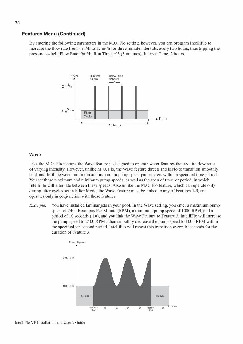
35
IntelliFlo VF Installation and User’s Guide
Features Menu (Continued)
By entering the following parameters in the M.O. Flo setting, however, you can program IntelliFlo to increase the flow rate from 4 m3/h to 12 m3/h for three minute intervals, every two hours, thus tripping the pressure switch: Flow Rate=9m3/h, Run Time=:03 (3 minutes), Interval Time=2 hours.
Wave
Like the M.O. Flo feature, the Wave feature is designed to operate water features that require flow rates of varying intensity. However, unlike M.O. Flo, the Wave feature directs IntelliFlo to transition smoothly back and forth between minimum and maximum pump speed pararmeters within a specified time period. You set these maximum and minimum pump speeds, as well as the span of time, or period, in which IntelliFlo will alternate between these speeds. Also unlike the M.O. Flo feature, which can operate only during filter cycles set in Filter Mode, the Wave Feature must be linked to any of Features 1-9, and operates only in conjunction with those features.
Example: You have installed laminar jets in your pool. In the Wave setting, you enter a maximum pump speed of 2400 Rotations Per Minute (RPM), a minimum pump speed of 1000 RPM, and a period of 10 seconds (:10), and you link the Wave Feature to Feature 3. IntelliFlo will increase the pump speed to 2400 RPM , then smoothly decrease the pump speed to 1000 RPM within the specified ten second period. IntelliFlo will repeat this transition every 10 seconds for the duration of Feature 3.
Flow
Time
FilterCycle
4 m3/h
12 m3/h
10 hours
Interval time=2 hours
Run time=3 min
Pump Speed
TimeFeature 3Start
1000 RPM
2400 RPM
:10 :20 :30 :40 :60Feature 3End
Filter cycleFilter cycle

36
IntelliFlo VF Installation and User’s Guide
Features Menu (Continued)
Pulse
Like the M.O. Flo and Wave features, the Pulse feature is designed for water features requiring flow rates of varying intensity. As with the Wave feature, the Pulse feature setting includes parameters for minimum and maximum pump speeds, and period, however these pararmeters function differently than in the Wave feature.
The Pulse feature randomly selects a pump speed between the minimum and maximum values you specify, and directs IntelliFlo to run at that speed for the span of time you enter for the “Period” parameter. At the end of that time period, the Pulse feature randomly selects another pump speed between the maximum and minimum values you specified and directs IntelliFlo to run at the new speed for the span of time entered in the “Period” parameter. Like the Wave feature, the Pulse feature must be linked to any of Features 1-9, and operates only in conjunction with those features.
Example: You have decided to use the Pulse feature to operate the laminar jets described in the Wave feature example above. In the Wave setting, you enter a maximum pump speed of 2400 Rotations Per Minute (RPM), a minimum pump speed of 1000 RPM, and a period of three seconds (:03), and you link the Wave Feature to Feature 3. IntelliFlo will randomly select a pump speed between 2400 RPM and 1000 RPM, and run the pump at that speed for three seconds. At the end of the three-second period, IntelliFlo will randomly select another pump speed between the mimimum and maximum speed of 2400 RPM and 1000 RPM, and run the pump at this new speed for three seconds. IntelliFlo will select new random pump speeds and run the pump at the new speed every three seconds for the duration of Feature 3.
Pump Speed
TimeFeature 3Start
1000 RPM
2400 RPM
:03 :06 :09 :12 :60Feature 3End
Filter cycle Filter cycle
Flow between 1000 RPM and 2400 RPM — randomly selected
:03 period }

37
IntelliFlo VF Installation and User’s Guide
Features Menu (Continued)
Features Settings
Name Value Description
F1-9, M.O. Flo Set Flow
4-29m3/h(Default 12m3/h)
Programs the rate of flow for feature 1 - 10
F3-9, M.O. Flo, Wave, Pulse
Activation
Enabled / Disabled(Default Disabled)
When this setting is set to Enabled, the feature activates at the time specified in the “Set Start Time” setting. If this setting is set to Disabled, the feature does not activate.
F1-2: Time Duration
1 minute - 10 Hours, or 00:01 - 10:00(Default 00:01)
Sets the length of time for which Feature 1 or 2 will operate. Time duration must be selected for Feature 1 and 2.
F3:Set Start time
00:00 - 23:59 Default 06:00 am)
Sets start time for feature 3
F3:Stop time
00:00 - 23:59 (Default 06:10)
Sets stop time for feature 3
F4:Start time
00:00 - 23:59 (Default 06:20)
Sets start time for feature 4
F4:Stop time
00:00 - 23:59 (Default 06:30 am)
Sets stop time for feature 4
F5:Start time
00:00 - 23:59 (Default 06:40)
Sets start time for feature 5
F5:Stop time
00:00 - 23:59 (Default 06:50 am)
Sets stop time for feature 5
F6:Start time
00:00 - 23:59 (Default 07:00)
Sets start time for feature 6
F6:Stop time
00:00 - 23:59 (Default 07:10 am)
Sets stop time for feature 6
F7:Start time
00:00 - 23:59 (Default 07:20)
Sets start time for feature 7
F7:Stop time
00:00 - 23:59 (Default 07:30)
Sets stop time for feature 7
F8:Start time
00:00 AM - 23:59 (Default 07:40)
Sets start time for feature 8
F8:Stop time
00:00 AM - 23:59 (Default 07:50)
Sets stop time for feature 8
F9:Start time
00:00 AM - 23:59 (Default 08:00)
Sets start time for feature 9
F9:Stop time
00:00 AM - 23:59 (Default 08:10)
Sets stop time for feature 9
M.O.FloSet Run time
1 - 59 minutes, or 00:01 - 00:59(Default 00:01)
Sets the duration of time over which the M.O.Flo feature will operate the pump at the intervals specified in the “Set Interval Time” setting, and at the rate specified in the “Set Flow” setting
M.O.FloSet Interval time
2 - 255 minutes, or 00:02 - 04:15(Default 60 minutes, or 01:00)
Sets the time between activations of the pump at the rate specified in the “Set Flow” setting
Wave, PulseFeature Linked
1-9(Wave Default 1, Pulse Default 2)
Refers to the feature to which the Wave or Pulse feature is linked
Wave, PulseSet Max Speed
450 - 3450 RPM(Default 3450 RPM)
Sets the highest pump speed, in Rotations Per Minute (RPM), at which the Wave or Pulse feature will operate
Wave, PulseSet Min Speed
400 - 3400 RPM(Default 400 RPM)
Sets the lowest pump speed, in Rotations Per Minute (RPM), at which the Wave or Pulse feature will operate
Wave, Pulse Period
Wave 10 - 300 seconds or 0010 - 0300
(Default 0010)Pulse 2 - 300 seconds or 0002 -
0300(Default 0002)
For the Wave feature, this setting sets the length of time it takes for the pump to transition between the values set in the “Max Speed” and “MIn Speed” settings. For the Pulse feature, this setting determines the length of time the pump will maintain a randomly generated speed between the values set in the “Max Speed” and “Min Speed” settings.

38
IntelliFlo VF Installation and User’s Guide
Features Menu (Continued)
Feature 1 or 2 Setup
To access the Features 1(2) menu:
1. Ensure that the green power LED is on and the pump is stopped.
2. Press the Menu button. “Pool Data” is displayed.
3. Use the Up and Down arrow buttons to scroll to the “Features” menu item. Press the Select button to select it. “Feature 1” is displayed. Use the Up and Down arrow buttons to scroll to the Feature 1 or Feature 2 menu item. Press the Select button to select one.
a) TosettheflowrateforFeature1or2: Press the Select button to access the Feature 1 (2) “Set Flow” setting (Default 12m3/h). To change the setting, see step 4, below.
b) To set the duration for Feature 1 or 2: Use the Up and Down arrow buttons to scroll to the “Time Duration” setting. Press the Select button to access it (Default 00:01). To change the setting, see step 4, below.
4. To change a setting, press the Left and Right arrows to select which digit to modify, then use the Up and Down arrows to change the selected digit.
5. When you are done, press the Enter button to shave the changes. To cancel any changes, press the Escape button to exit mode without saving.
Set Flow
MENU 12:15
Features
®
Feature 1 displaysFEATURES 12:15
Feature 1
®
Feature 1 12:15
12m³/hSet Flow
®
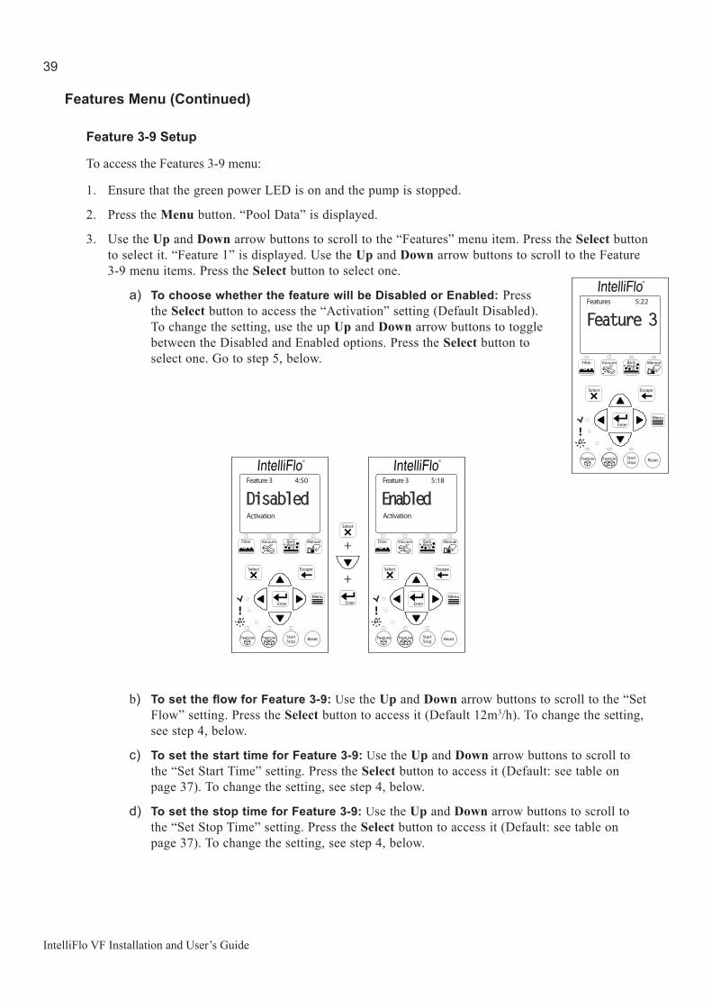
39
IntelliFlo VF Installation and User’s Guide
Features Menu (Continued)
Feature 3-9 Setup
To access the Features 3-9 menu:
1. Ensure that the green power LED is on and the pump is stopped.
2. Press the Menu button. “Pool Data” is displayed.
3. Use the Up and Down arrow buttons to scroll to the “Features” menu item. Press the Select button to select it. “Feature 1” is displayed. Use the Up and Down arrow buttons to scroll to the Feature 3-9 menu items. Press the Select button to select one.
a) To choose whether the feature will be Disabled or Enabled: Press the Select button to access the “Activation” setting (Default Disabled). To change the setting, use the up Up and Down arrow buttons to toggle between the Disabled and Enabled options. Press the Select button to select one. Go to step 5, below.
b) TosettheflowforFeature3-9:Use the Up and Down arrow buttons to scroll to the “Set Flow” setting. Press the Select button to access it (Default 12m3/h). To change the setting, see step 4, below.
c) To set the start time for Feature 3-9: Use the Up and Down arrow buttons to scroll to the “Set Start Time” setting. Press the Select button to access it (Default: see table on page 37). To change the setting, see step 4, below.
d) To set the stop time for Feature 3-9: Use the Up and Down arrow buttons to scroll to the “Set Stop Time” setting. Press the Select button to access it (Default: see table on page 37). To change the setting, see step 4, below.
Features 5:22
Feature 3
®
+
+
Feature 3 4:50
DisabledActivation
®
Feature 3 5:18
EnabledActivation
®

40
IntelliFlo VF Installation and User’s Guide
FilterCycle
Flow
Time
Flow
Time
10m3/h
8:00 22:00
Original Filter Cycle w/No Timed Feature
FilterCycle
Feature 3
8:00
10m3/h
20m3/h
21:0019:0018:00
New Flow/Time Optimized Filter Cycle
Features Menu (Continued)
4. To change a setting, press the Left and Right arrows to select which digit to modify, then use the Up and Down arrows to change the selected digit.
5. When you are done, press the Enter button to save the changes. To cancel any changes, press the Escape button to exit the setting without saving.
Feature 3-9 Operation
Feature 3-9 function as part of the filter cycles programmed in the Filter menu and IntelliFlo must be in Filter Mode for Feature 3-9 to operate. Unlike Feature 1(2), Feature 3-9 cannot be operated on an “on demand” basis. If Enabled is selected in the Feature 3-9 “Activation” setting, Feature 3-9 will start and stop at the times programmed in the Feature 3-9 settings menu whenever IntelliFlo is in Filter Mode. If Disabled is selected in the “Activation” setting, IntelliFlo will not run Feature 3-9.
The parameters you program for features Feature 3-9 supercede the filter cycle parameters you programmed for Filter Mode in the Filter settings menu. IntelliFlo will operate at the parameters you programmed for Filter Mode, until the time of day you programmed as the “Start” time for Features 3-9. At that time, IntelliFlo will switch to the flow rate you set for Features 3-9, and will operate at those parameters until the “Stop” time you entered for the feature. IntelliFlo will then resume the interrupted filter cycle at the point it left off, and will recalculate the the time it needs to run at the filter cycle flow rate to in order to complete the filter cycle (See page 31 for more information on using Feature 3-9 in conjunction with Filter Mode.).
41
IntelliFlo VF Installation and User’s Guide
Features Menu (Continued)
M.O. Flo Setup
To access the M.O. Flo menu:
1. Ensure that the green power LED is on and the pump is stopped.
2. Press the Menu button. “Pool Data” is displayed.
3. Use the Up and Down arrow buttons to scroll to the “Features” menu item. Press the Select button to select it. “Feature 1” is displayed. Use the Up and Down arrow buttons to scroll to the M.O. Flo menu item. Press the Select button to select it.
a) To choose whether the M.O. Flo feature will be Disabled or Enabled: Press the Select button to access the “Activation” setting (Default Disabled). To change the setting, use the up Up and Down arrow buttons to toggle between the Disabled and Enabled options. Press the Select button to select one. Go to step 5, below.
b) TosettheflowfortheM.O.Flofeature:Use the Up and Down arrow buttons to scroll to the “Set Flow” setting. Press the Select button to access it (Default 12m3/h). To change the setting, see step 4, below.
c) To set the run time for the M.O. Flo feature: Use the Up and Down arrow buttons to scroll to the“Set Run Time” setting. Press the Select button to access it (Default 1 minute, or 0:01). To change the setting, see step 4, below.
d) To set the interval time for the M.O. Flo feature: Use the Up and Down arrow buttons to scroll to the “Set Interval Time” setting. Press the Select button to access it (Default 1 hour, or 01:00). To change the setting, see step 4, below.
Features 7:22
M.O.Flo
®
M.0. Flo 7:29
DisabledActivation
®
M.O. Flo 7:29
12m³/hSet Flow
®
M.O. Flo
Set Run Time
7:30
0:01
®
M.O. Flo
Set Interval Time
7:31
1:00
®
Enable/ Disable Set Run Time Set Interval TimeSet Flow

42
IntelliFlo VF Installation and User’s Guide
Features Menu (Continued)
4. To change a setting, press the Left and Right arrows to select which digit to modify, then use the Up and Down arrows to change the selected digit.
5. When you are done, press the Enter button to shave the changes. To cancel any changes, press the Escape button to exit mode without saving.
M.O. Flo Operation
Like Feature 3-9, M.O. Flo functions as part of the filter cycles programmed in the Filter menu, and IntelliFlo must be in Filter Mode for M.O. Flo feature to operate. M.O. Flo cannot be operated on an “on demand” basis. If Enabled is selected in the M.O. Flo “Activation” setting , M.O. Flo will start and stop at the times programmed in the Setup Menu whenever IntelliFlo is in Filter Mode. If Disabled is selected in the “Activation” setting, IntelliFlo will not run the M.O. Flo feature.
Wave and Pulse Setup
To access the Wave or Pulse menus:
1. Ensure that the green power LED is on and the pump is stopped.
2. Press the Menu button. “Pool Data” is displayed.
3. Use the Up and Down arrow buttons to scroll to the “Features” menu item. Press the Select button to select it. “Feature 1” is displayed. Use the Up and Down arrow buttons to scroll to the “Wave” or “Pulse” menu item. Press the Select button to select it.
a) To choose whether the Wave or Pulse feature will be Disabled or Enabled: Press the Select button to access the “Activation” setting (Default Disabled). To change the setting, use the up Up and Down arrow buttons to toggle between the Disabled and Enabled options. Press the Select button to select one. Go to step 5, below.
b) To specify the feature to which to link the Wave or Pulse feature: Use the Up and Down arrow buttons to scroll to the “Feature Linked” setting. Press the Select button to access it (Wave default 1, Pulse default 2). To change the setting, see step 4, below.
c) To set the maximum pump speed for the Wave or Pulse feature: Use the Up and Down arrow buttons to scroll to the“Set Max Speed” setting. Press the Select button to access it (Default 3450 RPM). To change the setting, see step 4, below.
d) To set the minimum pump speed for the Wave or Pulse feature: Use the Up and Down arrow buttons to scroll to the “Set Min Speed” setting. Press the Select button to access it (Default 3400 RPM). To change the setting, see step 4, below.
e) To set the period length for the Wave or Pulse feature: Use the Up and Down arrow buttons to scroll to the “Period” setting. Press the Select button to access it (Default 10 seconds, or 0010). To change the setting, see step 4, below
43
IntelliFlo VF Installation and User’s Guide
Features Menu (Continued)
4. To change a setting, press the Left and Right arrows to select which digit to modify, then use the Up and Down arrows to change the selected digit.
5. When you are done, press the Enter button to shave the changes. To cancel any changes, press the Escape button to exit mode without saving.
Wave and Pulse Operation
The Wave and Pulse Features operate in conjunction with Features 1-9, and must be linked (See page 35) to any of those features in order to operate. If the Wave or Pulse feature is linked to Feature 1 or 2, then the operation of these features is controlled through the Feature 1 and Feature 2 buttons.
1. Press the Feature 1 or Feature 2 button, then press the Start/Stop button. IntelliFlo will activate the feature and the active feature LED will be lit until the feature has finished operation. The Wave or the Pulse feature will activate at the same time, and continue to operate for as long Feature 1 or 2 operates.
2. The “Feature 1” screen will display a countdown of the time remaining in the duration you programmed for that feature. By using the Up and Down arrow buttons, you can switch between screens displaying current flow, power usage in Watts (W), and pump speed in RPM.
If the Wave or Pulse feature is linked to Feature 3-9, then the feature functions as part of the filter cyles programmed in the Filter settings menu, and IntelliFlo must be in Filter Mode for Wave or Pulse to operate. IntelliFlo will activate the Wave or Pulse feature whenver it activates the feature to which it is linked. For example, if the Pulse Feature is linked to Feature 3 and Feature 3 is programmed to start at 15:00, the Pulse feature will activate at 15:00 in conjunction with Feature 3, and will continue to operate for as long Feature 3 operates. If Feature 3-9 is disabled, the Wave or Pulse feature linked to it will not operate.
Like Features 3-9 and M.O. Flo, Wave and Pulse may be enabled or disabled in the “Activation” Setting (See page 35). If Enabled is selected in the Wave or Pulse “Activation” setting (See “Wave and Pulse Setup” on page 35) , the feature will start and stop whenever the feature it is linked to starts and stops. If Disabled is selected in the Wave or Pulse “Activation” setting, or if the feature to which Wave or Pulse is linked is itself disabled, IntelliFlo will not run the feature.

44
IntelliFlo VF Installation and User’s Guide
External Control Menu
External Control Setup with IntelliComm
External Control Mode is activated and operated through the IntelliComm communication center. See “External Control Mode” on page 20 for more information on operating the IntelliFlo by remote control.
To access the Ext. Ctrl. menu:
1. Ensure that the green power LED is on and the pump is stopped.
2. Press the Menu button. “Pool Data” is displayed.
3. Use the Up and Down arrow buttons to scroll to the “Ext. Ctrl.” menu item. Press the Select button to select it. “Program 1” is displayed. Use the Up and Down arrow buttons to scroll to the desired program (Program 1-4) and press the Select button to select it.
MENU 12:00
Ext. Ctrl.
®
Ext. Ctrl. 12:07
Program 1
®
Ext. Ctrl. 12:08
Program 2
®
Ext. Ctrl. 12:10
Program 3
®
Ext. Ctrl. 12:11
Program 4
®
a) To choose whether the program will be Disabled or Enabled: Press the Select button to access the “Activation” setting (Default Enabled). To change the setting, use the up Up and Down arrow buttons to toggle between the Disabled and Enabled options. Press the Select button to select one. Go to step 5, below.
b) TosettheflowusingExternalControls: Use the Up and Down arrow buttons to scroll to the “Set Flow” setting. Press the Select button to access it (Default 12m3/h). To change the setting, see step 4, below.
Program 1 12:16
12m³/hSet Flow
®
Program 1 12:14
EnabledActivation
®

45
IntelliFlo VF Installation and User’s Guide
External Control Menu (Continued)
c) To set the Time Delay Stop parameter: Use the Up and Down arrow buttons to scroll to the “Time Delay Stop” setting. Press the Select button to access it (Default 0, or 00:00). To change the setting, see step 4, below.
4. To change a setting, press the Left and Right arrows to select which digit to modify, then use the Up and Down arrows to change the selected digit.
5. When you are done, press the Enter button to shave the changes. To cancel any changes, press the Escape button to exit mode without saving.
Program 1 12:16
0:00Time Delay Stop
®
Backwash Menu
The Backwash menu is used to set the parameters for Backwash Mode (See page 17 for more information on Backwash Mode.).
Backwash Setup
To access the Backwash menu:
1. Ensure that the green power LED is on and the pump is stopped.
2. Press the Menu button. “Pool Data” is displayed.
3. Use the Up and Down arrow buttons to scroll to the “Backwash” menu item. Press the Select button to select it.
a) TosettheBackwashflowrate: Press the Select button to access the “Backwash Flow” setting (Default 14m3/h). To change the setting, go to step 4, below.
b) To set the Backwash duration: Use the Up and Down arrow buttons to scroll to the “Backwash Duration” setting. Press the Select button to access it (Default 5 minutes, or 0:05). To change the setting, see step 4, below.
c) To set the Rinse duration: Use the Up and Down arrow buttons to scroll to the “Rinse Duration” setting. Press the Select button to access it (Default 1 minute, or 0:01). To change the setting, see step 4, below.
Backwash
Backwash Flow
8:01
14m³/h
®
Backwash 8:01
0:05Backwash Duration
®
Rinse Duration
Backwash 8:02
0:01
®
4. To change a setting, press the Left and Right arrows to select which digit to modify, then use the Up and Down arrows to change the selected digit.
5. When you are done, press the Enter button to shave the changes. To cancel any changes, press the Escape button to exit mode without saving.
MENU 7:55
Backwash
®

46
IntelliFlo VF Installation and User’s Guide
Vacuum Menu
Vacuum Mode Setup
To access the Vacuum menu:
1. Ensure that the green power LED is on and the pump is stopped.
2. Press the Menu button. “Pool Data” is displayed.
3. Use the Up and Down arrow buttons to scroll to the “Vacuum” menu item. Press the Select button to select it. “Vacuum Flow” is displayed.
a) TosettheflowrateforVacuumMode: Press the Select button to access the “Vacuum Flow” setting (Default 12 m3/h). To change the setting, see step 4, below.
b) To set the duration Vacuum Mode: Use the Up and Down arrow buttons to scroll to the “Vacuum Duration” setting. Press the Select button to access it (Default 1 minute, or 00:01). To change the setting, see step 4, below.
Vacuum 12:15
12m³/hVacuum Flow
®
VACUUM 12:15
0:01VACUUM DURATION
®
4. To change a setting, press the Left and Right arrows to select which digit to modify, then use the Up and Down arrows to change the selected digit.
5. When you are done, press the Enter button to shave the changes. To cancel any changes, press the Escape button to exit mode without saving.
MENU 8:09
Vacuum
®

47
IntelliFlo VF Installation and User’s Guide
Section 4User Maintenance
The following information describes how to service and maintain the IntelliFlo pump.
Pump Strainer BasketThe strainer, sometimes referred to as the “Hair and Lint Pot,” at the front of the pump. The Hair and Lint Pot contains a basket which must be kept clean of leaves and debris at all times. To inspect for leaves and debris, view the basket through the top, see-through lid.
Regardless of the length of time between filter cleaning, it is most important to inspect the hair and lint pot basket visually at least once a week. A dirty basket will reduce the efficiency of the filter, and possibly the heater.
WARNING — DO NOT open the strainer pot if pump fails to prime or if pump has been operating without water in the strainer pot. Pumps operated in these circumstances may experience a build up of vapor pressure and may contain scalding hot water. Opening the pump may cause serious personal injury. In order to avoid the possibility of personal injury, make sure the suction and discharge valves are open and that the strainer pot is cool to the touch, then open with extreme caution.
CAUTION — To prevent damage to the pump and filter and for proper operation of the system, clean pump strainer and skimmer baskets regularly.
Servicing the Pump Strainer Basket
If the IntelliFlo pump is installed below the water level of the pool, close the return and suction lines before opening the hair and lint pot on the pump.
1. Place the IntelliFlo in “Manual” mode. Press the Start/Stop button to stop the pump and switch off the pump at the circuit breaker.
2. Disconnect the communication cable from the IntelliFlo pump.3. Relieve pressure in the system.4. Turn the clamp and lid in a counterclockwise direction until it
stops.5. Remove the clamp and lid.6. Remove the basket and put the debris into the trash and rinse out
the basket. If the basket is cracked, replace the basket.7. Replace the basket and fill the pump pot and volute with water up
to the inlet port.8. Clean the cover, O-ring, and sealing surface of the pump pot. Grease
the O-ring with Teflon or silicone lubricant.9. Reinstall the lid by placing the clamp and the lid on the pot.
Clamp, pot
Lid
O-ring, lid
Basket
Pot volute
48
IntelliFlo VF Installation and User’s Guide
Pump Strainer Basket Service (Continued)
10. Ensure that the lid o-ring is properly placed. Seat the clamp and lid then turn clockwise until the handles are horizontal as shown.
11. Reconnect the communication cable to the pump if required.12. Switch the power ON at the circuit breaker. Reset the pool time clock to the correct time.
WARNING - FILTER OPERATES UNDER HIGH PRESSURE. WHEN ANY PART
OF THE CIRCULATING SYSTEM (e.g., LOCK RING, PUMP, FILTER, VALVES, ETC.) IS SERVICED, AIR CAN ENTER THE SYSTEM AND BECOME PRESSURIZED. PRESSURIZED AIR CAN CAUSE THE LID TO BLOW OFF WHICH CAN RESULT IN SEVERE INJURY, DEATH, OR PROPERTY DAMAGE. TO AVOID THIS POTENTIAL HAZARD, FOLLOW
THESE INSTRUCTIONS.
13. Open the manual air relief valve on top of the filter.14. Stand clear of the filter. Press the Start button on the pump.15. Bleed air from the filter until a steady stream of water comes out.16. Close the manual air relief valve.
Motor Service
1. Protect from heat:• Shade the motor and controller from the sun.• Any enclosure must be well ventilated to prevent overheating. Particular attention should be paid to
the motor fan cover and the cooling fins between the drive and the motor.• Provide ample cross ventilation.
2. Protect against dirt:• Protect from any foreign matter or splashing water.• Do not store (or spill) pool chemicals near the motor.• Avoid sweeping or stirring up dust near the motor while it is operating.• If a motor has been damaged by dirt it voids the motor warranty.
3. Protect against moisture:• Protect from splashing pool water.• Protect from the weather.• Protect from lawn sprinklers.• If a motor has become wet - let it dry before operating. Do not allow the pump to operate if it has been
flooded.• If a motor has been damaged by water it voids the motor warranty.
Note: DO NOT wrap motor and controller with plastic or other air tight materials. The motor and controller may be covered, but not wrapped in plastic, during a storm, for winter storage, etc., but never when operating, or expecting operation. When replacing the motor, be certain that the motor support is correctly positioned to support the size of motor being installed.
ClampLid
Volute
49
IntelliFlo VF Installation and User’s Guide
Manual Priming and Initial Start-up After Service
Before a system start-up, the pump and system must be manually primed. Make sure to reopen valves before operating. To prime IntelliFlo, the strainer pot must be filled with water.
CAUTION — DO NOT run the pump dry. If the pump is run dry, the mechanical seal will be damaged and the pump will start leaking. If this occurs, the damaged seal must be replaced. ALWAYS maintain proper water level in your pool. Continued operation in this manner could cause a loss of pressure, resulting in damage to the pump case, impeller and seal.
To prime the IntelliFlo pump:
1. Turn the pump clamp and lid in a counterclockwise direction until it stops and remove them.2. Fill the pump strainer pot with water.3. Reinstall the pump clamp and lid onto the strainer pot. The pump is now ready to prime.
Winterizing
The IntelliFlo’s internal anti-freeze protection is disabled when connected to an IntelliTouch. Freeze protection is provided by selecting YES at the ON WITH FREEZE portion of the IntelliTouch’s appropriate circuit function menu. To re-enable the IntelliFlo’s internal anti-freeze protection, the power to the drive must be cycled off then back on.
1. If the air temperature drops below 35° F the water in the pump can freeze and cause damage. Freeze damage is not warrantable.
2. To prevent freeze damage follow the procedures listed below.• Shut off electrical power for the pump at the circuit breaker.• Drain the water out of the pump by removing the two thumb-twist drain plugs located at the bottom of
the volute. Store the plugs in the pump basket.• Cover the motor to protect it from severe rain, snow and ice.• Do not wrap the motor in plastic. It will cause condensation and rust on the inside of the motor.
Note: In mild climate areas, when temporary freezing conditions may occur, run your filtering equipment all night to prevent freezing.
ClampLid
Volute

50
IntelliFlo VF Installation and User’s Guide
4. Make sure all electrical connections are clean and tight.
5. Open the air release valve on the filter, and stand clear of the filter.
6. Switch the IntelliFlo on at the circuit breaker. Ensure that the green power LED is on.
7. Press the Manual button (LED on) to place IntelliFlo in manual mode.
8. Use the Up and Down arrows to select Set Speed, then press the Select button to edit the setting.
7. Adjust speed as necessary. Press the Left and Right arrows to select which digit to modify, then use the Up and Down arrows to change the speed. Press the Enter button to save the changes. To cancel any changes, press the Escape button to exit edit mode without saving.
9. Press the Start/Stop button to start the pump.
10. When water comes out of the air release valve, close the valve. The system should now be circulating water back to the pool without air bubbles showing in either the hair and lint pot or at the pool return fittings.

51
IntelliFlo VF Installation and User’s Guide
Section 5Installation and Removal
The following general information describes how to install the IntelliFlo pump.
Attention Installer: Before installing the IntelliFlo pump, read and follow all warning notices, instructions and safety precautions on pages 3, 4 and 5.
Installing the IntelliFloOnly a qualified service person should install the IntelliFlo.
Location
1. Install the pump as close to the pool or spa as possible. To reduce friction loss and improve efficiency, use short and direct suction and piping returns.
2. Install a minimum of 1,5 m or five (5) feet from the inside wall of the pool and spa. Canadian installations require a minimum of three (3) meters from pool water.
3. Install the pump a minimum of 60 cm or two (2) feet from the heater inlet.
4. Do not install the pump more than 2,5 m or (8) feet above the water level.
5. Install the pump in a sheltered well ventilated location protected from excessive moisture, (i.e., rain, sprinklers, etc.).
6. For hot tubs and spas, do not install within an outer enclosure or beneath the skirt of a hot tub or spa.
7. Install the pump with a rear clearance of at least 15 cm or 6 inches so that the motor can be removed easily for maintenance and repair.
Piping
For improved pool plumbing, it is recommended to use a larger pipe size. When installing the inlet and outlet fittings (male adaptors), use thread sealant.
Do not install 90° elbows directly into pump inlet or outlet. A valve, elbow or tee installed in the suction line should be no closer to the front of the pump than five (5) times the suction line pipe diameter (i.e., 5 cm or two (2) inch pipe requires a 25 cm or ten (10) inch straight run in front of the suction inlet of the pump). This will help the pump prime faster and last longer.
Flooded suction systems should have gate valves installed on suction and discharge pipes for maintenance, however, the suction gate valve should be no closer than five (5) times the suction pipe diameter as described above.
Check Valves
Check valves must be used when an IntelliFlo is used in parallel with other pumps. IntelliFlo pumps cannot be connected in series with other pumps.
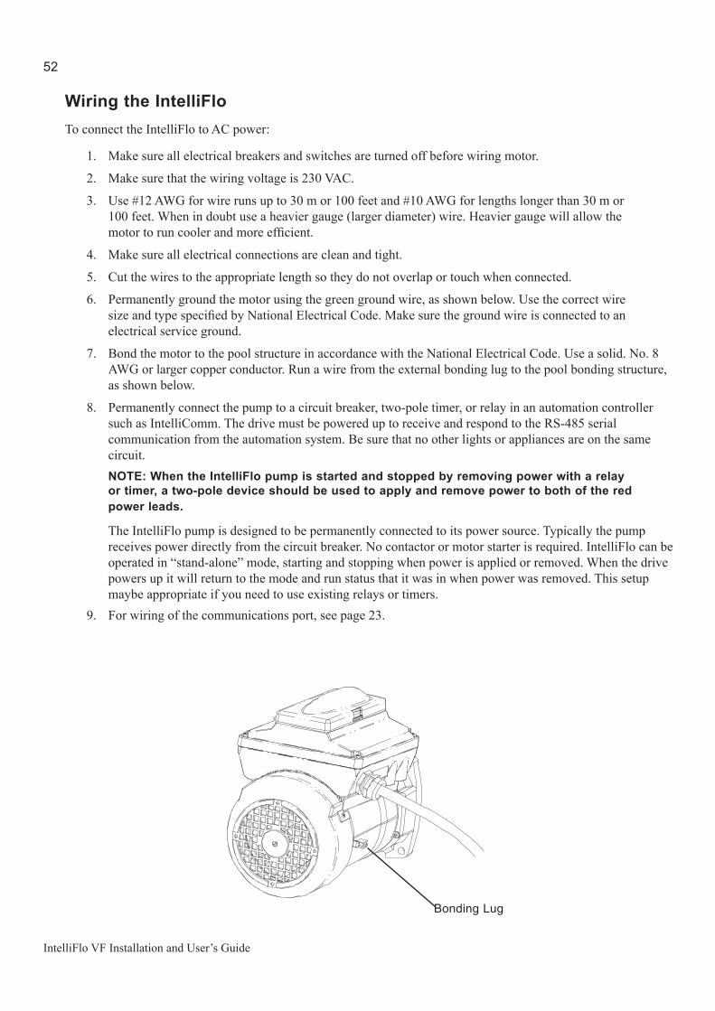
52
IntelliFlo VF Installation and User’s Guide
Wiring the IntelliFloTo connect the IntelliFlo to AC power:
1. Make sure all electrical breakers and switches are turned off before wiring motor.
2. Make sure that the wiring voltage is 230 VAC.
3. Use #12 AWG for wire runs up to 30 m or 100 feet and #10 AWG for lengths longer than 30 m or 100 feet. When in doubt use a heavier gauge (larger diameter) wire. Heavier gauge will allow the motor to run cooler and more efficient.
4. Make sure all electrical connections are clean and tight.
5. Cut the wires to the appropriate length so they do not overlap or touch when connected.
6. Permanently ground the motor using the green ground wire, as shown below. Use the correct wire size and type specified by National Electrical Code. Make sure the ground wire is connected to an electrical service ground.
7. Bond the motor to the pool structure in accordance with the National Electrical Code. Use a solid. No. 8 AWG or larger copper conductor. Run a wire from the external bonding lug to the pool bonding structure, as shown below.
8. Permanently connect the pump to a circuit breaker, two-pole timer, or relay in an automation controller such as IntelliComm. The drive must be powered up to receive and respond to the RS-485 serial communication from the automation system. Be sure that no other lights or appliances are on the same circuit.
NOTE: When the IntelliFlo pump is started and stopped by removing power with a relay or timer, a two-pole device should be used to apply and remove power to both of the red power leads.
The IntelliFlo pump is designed to be permanently connected to its power source. Typically the pump receives power directly from the circuit breaker. No contactor or motor starter is required. IntelliFlo can be operated in “stand-alone” mode, starting and stopping when power is applied or removed. When the drive powers up it will return to the mode and run status that it was in when power was removed. This setup maybe appropriate if you need to use existing relays or timers.
9. For wiring of the communications port, see page 23.
Bonding Lug

53
IntelliFlo VF Installation and User’s Guide
FIELD WIRING COMPARTMENT CONNECTIONS
L1 = HOT LEADL2 = HOT LEADGREEN SCREW = GROUND LEAD
BONDING LUG
GROUND WIRE CONNECTION
Wiring the IntelliFlo VF (for models with side AC Power connection)NOTE THIS WORK MUST BE DONE BY THE QUALIFIED ELECTRICIAN in accordance with the national wiring rules (AS/NZS 3000) taking into account its ratings (Class I, IPX5).To connect the IntelliFlo to AC power:
1. Make sure all electrical breakers and switches are turned off before wiring motor.2. Make sure that the wiring voltage is 230 VAC. 3. Use #12 AWG for wire runs up to 30 m or 100 feet and #10 AWG for lengths longer than 30 m or 100
feet. When in doubt use a heavier gauge (larger diameter) wire. Heavier gauge will allow the motor to run cooler and more efficient.
The IntelliFlo pump is supplied with the flying supply leads intended for permanent connection to fixed wiring. Typically the pump receives power directly from the circuit breaker. No contactor or motor starter is required. IntelliFlo can be operated in “stand-alone” mode, starting and stopping when power is applied or removed. When the drive powers up it will return to the mode and run status that it was in when power was removed. This setup maybe appropriate if you need to use existing relays or timers. Permanently connect the pump to a suitably rated circuit breaker, two-pole timer, or relay in an automation controller such as IntelliComm. The drive must be powered up to receive and respond to the RS-485 Serial communication from the automation system. Be sure that no other lights or appliances are on the same circuit. The IntelliFlo pump must be installed with a switch to ensure all-pole disconnection from the supply mains in accordance with the Wiring Rules. The switch shall be directly connected to the supply terminals and shall have a contact separation in all poles, providing full disconnection under overvoltage category III conditions.The pump must be also supplied through a residual current device – RCD (also known as an Electrical Leakage Circuit breaker –ELCB) with a maximum rated residual current of 30 mA and isolation/disconnecting device unless the circuit breaker is compliant with both functions/requirements. NOTE — Use only RCD/ELCB suitable for protecting equipment with a DC current content in the fault current.4. Bond the motor to the pool structure in accordance with the Wiring rules. Use a solid 4mm² or
larger copper conductor. Run a wire from the external equipotential bonding lug to the pool bonding structure, as shown below.
5. The pump should be permanently connected to either a circuit breaker, 2-pole timer or 2-pole relay. If AC power is supplied by a GFCI circuit breaker, use a dedicated circuit breaker that has no other electrical loads.
6. IMPORTANT: When connecting the pump to an automation system (IntelliComm), continuous power must be supplied to the pump by connecting it directly to the circuit breaker. When using an automation system, Be sure that no other lights or appliances are on the same circuit.
NOTE: When the IntelliFlo VS is started and stopped by removing power with a relay or timer, a two-pole device should be used to apply and remove power to both POWER LINE TERMINALS.
54
IntelliFlo VF Installation and User’s Guide
Pump Disassembly
WARNING — Always disconnect power to the pool pump at the circuit breaker before servicing the pump. Failure to do so could result in death or serious injury to serviceman, pool users or others due to electric shock.
Read all servicing instructions before working on the pump.
WARNING — DO NOT open the strainer pot if pump fails to prime or if pump has been operating without water in the strainer pot. Pumps operated in these circumstances may experience a build up of vapor pressure and may contain scalding hot water. Opening the pump may cause serious personal injury. In order to avoid the possibility of personal injury, make sure the suction and discharge valves are open and strainer pot temperature is cool to touch, then open with extreme caution.
CAUTION — Be sure not to scratch or mar the polished shaft seal faces; seal will leak if faces are damaged.
All moving parts are located in the rear sub-assembly of the IntelliFlo pump.
Tools required:
• 3/32 inch Allen head wrench.• ½ inch open end wrench.• 9/16 inch open end wrench.• Flat blade screwdriver.
To remove and repair the pump mechanical seal, perform the following procedures:
1. Switch off the pump circuit breaker at the main panel.2. Disconnect the communication cable from the pump.3. Drain the pump by removing the drain plugs.4. Remove the six bolts that hold the main pump body (strainer pot/volute) to the rear sub-assembly.5. GENTLY pull the two pump halves apart, removing the rear sub-assembly.6. Use a 3/32 inch Allen head wrench to loosen the two holding screws located on the diffuser.7. Hold the impeller securely in place and remove the impeller lock screw by using a Phillips head
screwdriver. The screw is a left-handed thread and loosens in a clockwise direction.8. Use a flat blade screwdriver to hold the motor shaft. The motor shaft has a slot on the end which is
accessible through the center of the fan cover.

55
IntelliFlo VF Installation and User’s Guide
Pump Disassembly (Continued)
9. To unscrew the impeller from the shaft, twist the impeller counterclockwise.
10. Remove the rotating portion of the mechanical seal from the impeller.
11. Remove the four bolts from the seal plate to the motor, using a 9/16 inch wrench.
12. Place the seal plate face down on a flat surface and tap out the carbon spring seat.
13. Clean the seal plate, seal housing, and the motor shaft.
Pump Reassembly/Seal Replacement
1. When installing the replacement shaft seal, use silicone sealant on the metal portion before pressing into the seal plate as shown above.
2. Before installing the rotating portion of the seal into the impeller, be sure the impeller is clean. Use a light density soap and water to lubricate the inside of the seal. Press the seal into the impeller with your thumbs and wipe off the ceramic and carbon faces with a clean cloth.
3. Remount the seal plate to the motor.4. Grease the motor shaft thread and screw impeller onto the motor shaft.5. Screw in the impeller lock screw (counterclockwise to tighten).6. Remount the diffuser onto the seal plate. Make sure the plastic pins and holding screw inserts are aligned.7. Grease the diffuser O-ring and seal plate gasket prior to reassembly.8. Grease the bolt threads, assemble the motor sub-assembly to the strainer pot-pump body by using the two
(2) through bolts for proper alignment. Do not tighten the through bolts until all six (6) bolts are in place and finger tightened.
9. Fill the pump with water.10. Reinstall the pump lid and plastic clamp then reprime the system, see page 43.
Shaft Seal Replacement
The Shaft Seal consists primarily of two parts, a rotating member and a ceramic seal. The pump requires little or no service other than reasonable care, however, a Shaft Seal may occasionally become damaged and must be replaced.
Note: The polished and lapped faces of the seal could be damaged if not handled with care.
SEAL PLATE
GASKET
IMPELLER
LOCKSCREW
LOCKSCREWSEAL
MOTOR SHAFT
SEAL
MOTOR BOLT
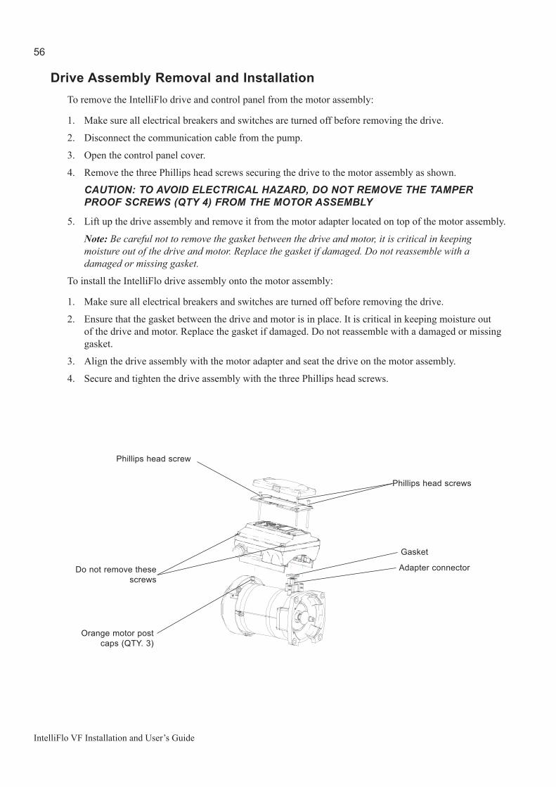
56
IntelliFlo VF Installation and User’s Guide
Drive Assembly Removal and InstallationTo remove the IntelliFlo drive and control panel from the motor assembly:
1. Make sure all electrical breakers and switches are turned off before removing the drive.
2. Disconnect the communication cable from the pump.
3. Open the control panel cover.
4. Remove the three Phillips head screws securing the drive to the motor assembly as shown.
CAUTION: TO AVOID ELECTRICAL HAZARD, DO NOT REMOVE THE TAMPER PROOF SCREWS (QTY 4) FROM THE MOTOR ASSEMBLY
5. Lift up the drive assembly and remove it from the motor adapter located on top of the motor assembly.
Note: Be careful not to remove the gasket between the drive and motor, it is critical in keeping moisture out of the drive and motor. Replace the gasket if damaged. Do not reassemble with a damaged or missing gasket.
To install the IntelliFlo drive assembly onto the motor assembly:
1. Make sure all electrical breakers and switches are turned off before removing the drive.
2. Ensure that the gasket between the drive and motor is in place. It is critical in keeping moisture out of the drive and motor. Replace the gasket if damaged. Do not reassemble with a damaged or missing gasket.
3. Align the drive assembly with the motor adapter and seat the drive on the motor assembly.
4. Secure and tighten the drive assembly with the three Phillips head screws.
Phillips head screws
Phillips head screw
Do not remove these screws
Adapter connector
Gasket
Orange motor post caps (QTY. 3)

57
IntelliFlo VF Installation and User’s Guide
22
25
1526
23
3
27
24
4
2
2817 29
11 18
16 1310
6 12 14 8 5 9 7 19
21
1
20
30
3133
Replacement Parts
Item No.
Part No. Description
1 070387 BASKET AQ & WF 2 070429 BOLT HEX HD, 2-56x0.875 s/s,
(QTY 4) 3 070430 BOLT 3/8 - 16 X 1¼ HEX CAP 18-8 s/s,
(QTY 4) 4 070431 BOLT 3/8 -16 X 2 HEX CAP 18-8 s/s,
(QTY 2) 5 357159 FOOT WF - PUMP MOTOR SUPPORT
(Black) 6 357160 FOOT INSERT WF PUMP (Black) 7 357161 PLUG DRAIN WFE (Black) (QTY 2) 8 071403 NUT 3/8 - 16 BRASS NICKEL PLATED,
(QTY 2) 9 071406 NUT ¼ - 20 HEX s/s (QTY 2) 10 071444 O-RING 238, 3.484x0.139, Buna-N 70 11 071652 SCREW ¼-20 X 1 LH PHILLIPS PAN
MS 18-8 s/s 12 071657 SCREW ¼ - 20 X 1 in. HEX CAP 18-8 s/s,
(QTY 2) 13 071660 SCREW SET 4-40 X 1-1/8 WFE SCKT
CAP 18-8 s/s (QTY 2) 14 072183 WASHER FLAT ¼ X 5/8 20 GA THICK
18-8 s/s (QTY 2)
Item No.
Part No. Description
15 072184 WASHER 3/8 ID X 7/8 OD .05 THICK 18-8 s/s, (QTY 6)
16 072928 DIFFUSER ASSEMBLY WFE 12 17 073131 IMPELLER WFE 12 1000 SER 18 075713 RUBBER WASHER WFE PUMP 19 192115 O-RING 112, 0.487x0.103
Buna-N 70 (QTY 2) 20 350013 O-RING LID CH/WF 2-436 21 357195 HOUSING WFE (Black) 22* 357290 CONTROL COVER ASSEMBLY (Black) 23* 351104 INTELLIFLO CE VAR-SPD MTR DRV
3.2 KW (Black) 24* 357294 VFD MOTOR 3.2 KW PMSM (Black) 25 350107 SCREW 10-24 X 3¼ in. PH MS 18-8 s/s,
(QTY 3) 26 350108 INTELLIFLO DRIVE GASKET 27 350142 SPACER CAP (QTY 3) 28 350101 SEAL PLATE KIT, WFE (Black) 29 357102 GASKET SANTOPRENE MOLDED 30 357156 LID SEE THRU WF 31 357150 CLAMP CAM & RAMP WF (Black) 32 359500 POT WF ASSY (Black) 33 351104 DRIVE (INCL. #22,25) Note: (*) Not serviceable parts.
Illustrated Parts List

58
IntelliFlo VF Installation and User’s Guide
IntelliFlo Pump Dimensions
IntelliFloElectricalSpecificationsCircuit Protection: Two-pole 20 AMP device at the Electrical Panel.
Input: 230 VAC, 50/60 Hz, 3200 Watts, 16 Amps
IntellifloPerformanceCurve
(31.8 cm)
(59.5 cm)(27.5 cm)
0.00
5.00
10.00
15.00
20.00
25.00
30.00
35.00
- 5.0 10.0 15.0 20.0 25.0 30.0 35.0
M3/ HR
ME
TER
S
3450 RPM
1500 RPM
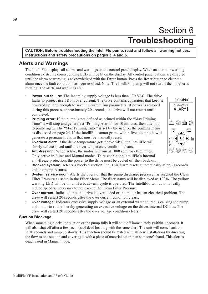
59
IntelliFlo VF Installation and User’s Guide
Alerts and WarningsThe IntelliFlo displays all alarms and warnings on the control panel display. When an alarm or warning condition exists, the corresponding LED will be lit on the display. All control panel buttons are disabled until the alarm or warning is acknowledged with the Enter button. Press the Reset button to clear the alarm once the fault condition has been resolved. Note: The IntelliFlo pump will not start if the impeller is rotating. The alerts and warnings are:
• Power out failure: The incoming supply voltage is less than 170 VAC. The drive faults to protect itself from over current. The drive contains capacitors that keep it powered up long enough to save the current run parameters. If power is restored during this process, approximately 20 seconds, the drive will not restart until completed.
• Priming error: If the pump is not defined as primed within the “Max Priming Time” it will stop and generate a “Priming Alarm” for 10 minutes, then attempt to prime again. The “Max Priming Time” is set by the user on the priming menu as discussed on page 25. If the IntelliFlo cannot prime within five attempts it will generate a permanent alarm that must be manually reset.
• Overheat alert: If the drive temperature gets above 54°C, the IntelliFlo will slowly reduce speed until the over temperature condition clears.
• Anti-freezing: When active, the motor will run at 1000 rpm for 60 minutes. Only active in Filter and Manual modes. To re-enable the IntelliFlo’s internal anti-freeze protection, the power to the drive must be cycled off then back on.
• Blocked system: Detects a blocked suction line. This alarm resets automatically after 30 seconds and the pump restarts.
• System service soon: Alerts the operator that the pump discharge pressure has reached the Clean Filter Pressure as setup in the Filter Menu. The filter status will be displayed as 100%. The yellow warning LED will be on until a backwash cycle is operated. The IntelliFlo will automatically reduce speed as necessary to not exceed the Clean Filter Pressure.
• Over current: Indicated that the drive is overloaded or the motor has an electrical problem. The drive will restart 20 seconds after the over current condition clears.
• Over voltage: Indicates excessive supply voltage or an external water source is causing the pump and motor to rotate thereby generating an excessive voltage on the drives internal DC bus. The drive will restart 20 seconds after the over voltage condition clears.
Suction BlockageWhen something blocks the suction or the pump fully it will shut off immediately (within 1 second). It will also shut off after a few seconds of dead heading with the same alert. The unit will come back on in 30 seconds and ramp up slowly. This function should be tested with all new installations by directing the flow to one suction and covering it with a piece of material other than someone’s hand. This alert is deactivated in Manual mode.
Section 6Troubleshooting
CAUTION: Before troubleshooting the IntelliFlo pump, read and follow all warning notices, instructions and safety precautions on pages 3, 4 and 5.
SystemBlock
ALARM!
®
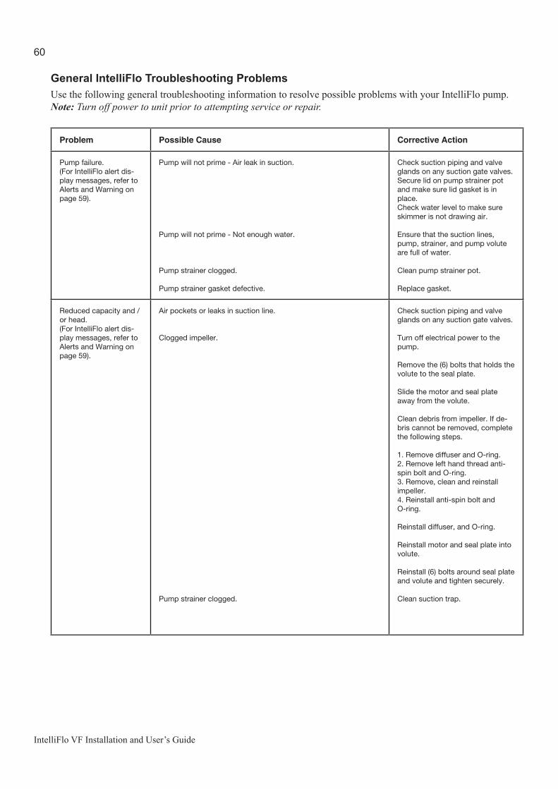
60
IntelliFlo VF Installation and User’s Guide
General IntelliFlo Troubleshooting ProblemsUse the following general troubleshooting information to resolve possible problems with your IntelliFlo pump.Note: Turn off power to unit prior to attempting service or repair.
Problem Possible Cause Corrective Action
Pump failure. (For IntelliFlo alert dis-play messages, refer to Alerts and Warning on page 59).
Pump will not prime - Air leak in suction.
Pump will not prime - Not enough water.
Pump strainer clogged.
Pump strainer gasket defective.
Check suction piping and valve glands on any suction gate valves.Secure lid on pump strainer pot and make sure lid gasket is in place.Check water level to make sure skimmer is not drawing air.
Ensure that the suction lines, pump, strainer, and pump volute are full of water.
Clean pump strainer pot.
Replace gasket.
Reduced capacity and /or head.(For IntelliFlo alert dis-play messages, refer to Alerts and Warning on page 59).
Air pockets or leaks in suction line.
Clogged impeller.
Pump strainer clogged.
Check suction piping and valve glands on any suction gate valves.
Turn off electrical power to the pump.
Remove the (6) bolts that holds the volute to the seal plate.
Slide the motor and seal plate away from the volute.
Clean debris from impeller. If de-bris cannot be removed, complete the following steps.
1. Remove diffuser and O-ring. 2. Remove left hand thread anti-spin bolt and O-ring. 3. Remove, clean and reinstall impeller.4. Reinstall anti-spin bolt and O-ring.
Reinstall diffuser, and O-ring.
Reinstall motor and seal plate into volute.
Reinstall (6) bolts around seal plate and volute and tighten securely.
Clean suction trap.

61
IntelliFlo VF Installation and User’s Guide
Troubleshooting Problems (Continued)
Problem Possible Cause Corrective Action
Inadequate circulation. (For IntelliFlo alert dis-play messages, refer to Alerts and Warning on page 59).
Pump overcurrent. Check trap basket; if plugged, turn pump off and clean basket. Suc-tion/discharge piping is too small. Check and clean pool filter.
Electrical problem.(For IntelliFlo alert dis-play messages, refer to Alerts and Warning on page 59).
Pump may be running too slowly.
Pump may be too hot.
Check voltage at motor terminals and at meter while pump is run-ning. If low, see wiring instructions or consult power company. Check for loose connections.
Check line voltage; if less than 90% or more than 110% of rated voltage consult a licensed electri-cian. Increase ventilation. Reduce ambient temperature. Tighten any loose wiring connec-tions. Motor internal terminal overload protector is open. Motor runs too hot. Turn power to motor off. Check for proper voltage. Check for proper impeller or impel-ler rubbing.
Mechanical Troubles and Noise.
The pump motor is running but with loud noise.
Cavitation.
If suction and discharge piping are not adequately supported, pump assembly will be strained. Do not mount pump on a wooden plat-form! Securely mount on concrete platform for quietest performance. Foreign matter (gravel, metal, etc.) in pump impeller. Disassemble pump, clean impeller, follow pump service instructions for reassem-bly.
Improve suction conditions. Increase pipe size. Decrease num-ber of fittings. Increase discharge pressure.

62
IntelliFlo VF Installation and User’s Guide
General Warnings• Never go inside the drive enclosure. There is a capacitor bank that holds a 230 VAC charge even
when there is no power to the unit.
• IntelliFlo is not submersible
• The pump is capable of 160 GPM or 104 feet of head; use caution when installing and programming to limit pumps performance potential with old or questionable equipment
• Code requirements for the electrical connection differ from state to state. Install equipment in accordance with the National Electrical Code and all applicable local codes and ordinances.
• There is no pressure limit in “Features” flow control
• Manual mode shuts off all sensors including Suction Blockage; use only in emergency or when metering a system.
• The unit needs constant power it is built to turn itself on / off
• Always stop the unit before performing maintenance
Electrical Cost OverviewTo calculate a system’s “Continuous Watts” use the following formula:
Amps X Volts X Power Factor = Continuous Watts
Examples:
• 1 HP E+ WhisperFlo = 7.4 amps X (230 Volt) X .90 PF = 1532 watts• 1 HP Max – E – Pro = 8.0 amps X (230 Volt) X .87 PF = 1600 watts
Once watts are computed, convert watts to kilowatts (kilo is 1000) and multiply this number by kilowatt/hour cost.
1 watt = .01 Kilowatt100 watts = .1 Kilowatt1000 watts = 1 Kilowatt1 HP E+ WhisperFlo 1532 watts or 1.532 Kilowatt x $.08 = $.122 per hour 1 HP Max-E-Pro 1600 watts or 1.600 Kilowatt x $.08 = $.128 per hour
The IntelliFlo does not require calculation for continuous watts since it is displayed on the screen in all modes. Just simply take the watts published on the screen, convert to kilowatts, and multiply by the kilowatt hour. The formula is:
210 watts = .210 kilowatt X $.08 = $.016 per hour
Remember to also consider the amount of water moved for the cost incurred (Water to Wire Efficiency). The IntelliFlo cannot be matched in today’s industry for flow versus continuous watts at any speed by any other pump in pool. The Filter mode and flow control further assists in cost saving by always allowing the pump to do the least amount of work at all times.
FILTER 12:30
210.WPOWERRUNNING Schedule
®

63
IntelliFlo VF Installation and User’s Guide
Swimming pools are great for relaxing, exercising or just having fun. But they also mean higher than average energy bills. The key to saving energy with your pool is to correctly manage the filter pump time, pool temperature and lighting. Consider the following when operating your swimming pool:
Using your IntelliFlo pump
Your pool needs to be filtered every 24 hours. The time to filter the pool depends on:
• The size of your pool.• The filtering equipment.• How much you use your pool.• Different environmental factors (such as how much sunlight hits the pool).
Typically, one complete turnover of water every 24 hours provides adequate filtering for a single-family pool. The more you use your pool, the more filtering it will need. It is generally recommended that you run your filter for four to six hours a day during the summer and two to four hours a day during the winter. If you’re filtering more than this, try reducing your daily filtering time by 30 minutes. After a week, if the water clarity and chemical balance show adequate filtration is taking place, try reducing your filtering time by another 30 minutes. Continue this process until water clarity or chemical imbalance indicates more filtering is needed. In addition to chemical testing, a good way to check your water clarity is that the main drain cover should be clearly visible from the deck.
Automatic pool sweeps (booster pump style)
Usually, three to four hours of daily operation during summer and two to three hours daily in the winter are sufficient. Start the pool sweep one hour or more after the pool pump has started and stop the sweep one hour or more before the pool pump turns off. On unusually dusty days, increase cleaning time in half-hour increments until the pool is clean. Use a wall brush and leaf skimmer frequently to help the sweep along.
Filter during off-peak times
You can help everyone by filtering your pool during off-peak hours. Avoid operating your pool filter between the hours of noon and 18:00. This will help reduce the demand for electricity, conserve natural resources, and save money. Of course, if your pool has solar heating, you’ll need to filter when the sun is correctly positioned for your solar panels. However, we recommend that you minimize filtration during the peak period of noon to 18:00 as much as possible.
Settingfilteringtime
A filter time clock is an easy way to manage pool filtering. Just be sure to check it once a month to make sure the trippers are secure. Check your clock’s instruction manual for directions on setting the operation times. Remember to reset the time clock after power outages and for the fall and spring time change.
Howtomakeyourpoolmoreenergyefficient

64
IntelliFlo VF Installation and User’s Guide
Preventive maintenance
Follow a regular program of preventive maintenance, including an annual inspection of the heat exchanger to help maintain heating efficiency.
EnergyEfficientIntelliFlopump
When its time to replace your old motor and pump assembly, consider using the IntelliFlo variable flow energy-efficient pump. It moves more water more efficiently, and can help you reduce your filter operating time by hours. IntelliFlo can automatically control tasks like pool vacuuming, filtering and backwashing, operating the automatic pool sweep and pump operation for the pool/spa combination. Once these tasks are done, IntelliFlo automatically ramps down to low speed for your pool’s daily filtration cycle, which can save energy and money for you.
Pentair warrants that, when this product is used for the purpose it was designed, is correctly housed and vented against weather, vermin, dust etc., that it will be free of material and manufacturing defects at the time of the original purchase. This warranty is limited to the cost of the product and does not cover third party costs including the costs of electricians, plumbers, etc. unless authorised by Pentair.
TERMS AND CONDITIONS APPLICABLE
1) YOU SHOULD CAREFULLY READ THE INSTRUCTIONS SUPPLIED PRIOR TO USING THIS PENTAIR PRODUCT. This product is to be installed and operated in accordance with the instructions provided. This warranty will not apply if it is used in a manner other than in accordance with the instructions.
What the warranty covers:Pentair warrants its products to be free of defects in material and workmanship during the warranty period. If a product proves to be defective in material or workmanship during the warranty period, then Pentair will, at its sole option repair or replace the product with a like product. Replacement product or parts may include re-manufactured or refurbished parts or components.How long the warranty is effective: This Pentair product is warranted for three (3) years for all parts from the date of the first consumer purchase.
Who the warranty protects: This warranty is valid only for the consumer purchaser. What the warranty does not cover:1) Damage, deterioration or malfunction resulting from:
a) accident, misuse, negligence, fire, water, lightning, or other acts of nature, unauthorised product modification or failure to follow instructions supplied with the product;
b) repair or attempted repair by anyone not authorised by Pentair; c) any damage to the product due to shipment; d) removal or installation of the product;e) causes external to the product such as electric power fluctuations or failure; f) use of supplies or parts not meeting Pentair specifications; g) normal wear and tear; h) water ingression or exposure to abnormal corrosive conditions or “run dry” conditions; i) any other cause which does not relate to a product defect.
2) Damage caused to the product as a consequence of use of another manufacturer’s product used in conjunction with Pentair and affiliate companies.3) Ingress of insects into the unit causing electrical malfunction is not warranted, care should be taken to avoid this occurrence.

65
IntelliFlo VF Installation and User’s Guide
Notes

Copyright – Limited License: except as specifically permitted herein, no portion of the content on this document may be reproduced in any form or by any mean without the prior written permission of Pentair International SRL.Copyright – Eingeschränkte Lizenz: soweit hierin nicht ausdrücklich zugelassen, dürfen die Inhalte dieses Dokuments ohne vorausgehende schriftliche Genehmigung der Pentair International SRL weder ganz noch auszugsweise und in gleich welcher Form und mit welchen Mitteln vervielfältigt werden.Copyright – Beperkte licentie: behalve zoals hierin specifiek toegestaan, mag geen enkel deel van de inhoud van dit document op om het even welke manier of hoe dan ook gereproduceerd worden zonder de voorafgaande schriftelijke toestemming van Pentair International SRL.Copyright – Licence limitée: sauf expressément autorisé ci-après, aucune partie du contenu de ce document ne peut être reproduite sous toute forme ou par tout moyen sans la permission écrite préalable de Pentair International SRL.Copyright – Licencia limitada: salvo en lo expresamente permitido en el presente documento, se prohíbe la reproducción total o parcial del mismo por cualquier medio sin la previa autorización por escrito de Pentair International SRL.Copyright – Licenza limitata: se non indicato specificatamente di seguito, nessuna porzione del contenuto di questo documento può essere riprodotta in qualsiasi forma o con qualsiasi mezzo senza preventiva autorizzazione scritta di Pentair International SRL. Protected by Patent Numbers: US-6966092; US-7159263; US-7401372; US-7284565; AU-2003253935; AU-2007214369; AU-2005280343; CA-2492464; ZA-2005/0469 European Patent Applications Nos. 03764706.2 and 05788949.5 and corresponding rights in other countries.
SAVE THESE INSTRUCTIONS !
PENTAIR AQUATIC SYSTEMS
INDUSTRIEPARK WOLFSTEE, TOEKOMSTLAAN 30, 2200 HERENTALS - BELGIUM, WWW.PENTAIRPOOLEUROPE.COM