intelligent air operated diaphragm pumps appendix pump iom.… · · 2017-05-22g = ¼” ep...
TRANSCRIPT

Intelligent Air Operated
Diaphragm Pumps appendix edition 2017 rev 1
This manual is an appendix. Use it together
with PE & PTFE, Metal or Sanitary AODD IOM
manual !!!
(depends on the product series)
Read this manual carefully,
before installation and operation of the pump
Plastic series: Metal series: Sanitary series:
TC50 TC70 TC80
TC100 TC120 TC125
TC200 TC220 TC225
TC400 TC420 TC425

CONTENTS
IOM manual IAODD appendix 2
0. GENERAL .......................................................................................................................................... 5
0.1. Introduction ................................................................................................................................. 5
0.2. Warning symbols ......................................................................................................................... 5
0.3. Qualification and training of personnel ....................................................................................... 5
1. INSTALLATION ................................................................................................................................. 6
1.1. Health and safety ......................................................................................................................... 6
1.1.1. Protection............................................................................................................................. 6
1.1.2. Electrical connections ........................................................................................................... 6
1.1.3. Explosion hazardous environments – ATEX.......................................................................... 6
1.1.4. Air pressure .......................................................................................................................... 6
1.2. Air connection .............................................................................................................................. 6
1.2.1. Internal Pilot (IP) / External Pilot (EP) ................................................................................... 7
1.2.2. Air treatment system ............................................................................................................ 9
1.3. Recommended installations ......................................................................................................... 9
1.3.1. Flooded ................................................................................................................................ 9
1.3.2. Self-priming ......................................................................................................................... 9
1.3.3. Submerged ........................................................................................................................ 10
1.4. Intelligent control module electric scheme ................................................................................ 10
2. OPERATION .................................................................................................................................... 11
2.1. Before starting the pump ........................................................................................................... 11
2.2. Pump stopping .......................................................................................................................... 11
3. MAINTENANCE .............................................................................................................................. 12
3.1. Routine inspection ..................................................................................................................... 12
3.2. Complete inspection .................................................................................................................. 12
3.3. Location of faults ....................................................................................................................... 13
3.4. T50/T70/T80 - Disassembly of the pump ................................................................................... 14
3.4.1. Before the disassembly procedure ..................................................................................... 14
3.4.2. Disassembly procedure ...................................................................................................... 14
3.4.3. Removing the air valve ....................................................................................................... 16
3.4.4. Detaching the Intelligent control module .......................................................................... 16
3.5. T50/T70/T80 – Assembly of the pump ....................................................................................... 17
3.5.1. Assembly of the air valve ................................................................................................... 17
3.5.2. Assembly of the diaphragm shaft. ..................................................................................... 18
3.5.3. Test run .............................................................................................................................. 19
3.6. T100 – T425 – Disassembly of the centerblock .......................................................................... 20
CONTENTS
IOM manual IAODD appendix 3
3.6.1. Before the disassembly procedure ..................................................................................... 20
3.6.2. Disassembly procedure ...................................................................................................... 20
3.6.3. Removing the muffler ........................................................................................................ 22
3.6.4. Detaching the Intelligent control module .......................................................................... 22
3.6.5. Removing the air valve ....................................................................................................... 23
3.7. T100 - 425 – Assembly procedure.............................................................................................. 24
3.7.1. Assembly of the centerblock .............................................................................................. 24
3.7.2. Assembly of the air valve ................................................................................................... 25
3.7.3. Test run .............................................................................................................................. 27
4. SPARE PARTS ................................................................................................................................. 28
4.1. TC50, TC70, T80: Intelligent pump Centerblock – Spare parts drawing ..................................... 28
4.2. TC50, TC70, TC80: Intelligent pump Centerblock – Spare parts list ........................................... 28
4.3. TC100, TC120, TC125: Intelligent pump Centerblock – Spare parts drawing ............................. 29
4.4. TC100, TC120, TC125: Intelligent pump Centerblock – Spare parts list ...................................... 29
4.5. TC200, TC220, TC225: Intelligent pump Centerblock – Spare parts drawing ............................. 31
4.6. TC200, TC220, TC225: Intelligent pump Centerblock – Spare parts list ...................................... 31
4.7. TC400, TC420, TC425: Intelligent pump Centerblock – Spare parts drawing ............................. 32
4.8. TC400, TC420, TC425: Intelligent pump Centerblock – Spare parts list ...................................... 32
4.9. Stocking recommendation ......................................................................................................... 33
5. WARRANTY .................................................................................................................................... 34
5.1. Warranty form ............................................................................................................................ 34
5.2. Returning parts .......................................................................................................................... 35
5.3. Warranty .................................................................................................................................... 35
CE CERTIFICATE
IOM manual IAODD appendix 4
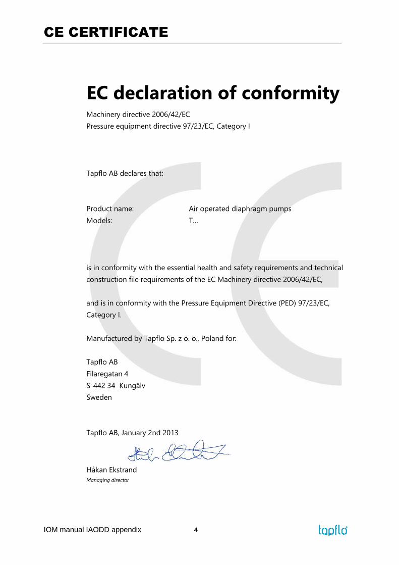
EC declaration of conformity Machinery directive 2006/42/EC
Pressure equipment directive 97/23/EC, Category I
Tapflo AB declares that:
Product name: Air operated diaphragm pumps
Models: T…
is in conformity with the essential health and safety requirements and technical
construction file requirements of the EC Machinery directive 2006/42/EC,
and is in conformity with the Pressure Equipment Directive (PED) 97/23/EC,
Category I.
Manufactured by Tapflo Sp. z o. o., Poland for:
Tapflo AB
Filaregatan 4
S-442 34 Kungälv
Sweden
Tapflo AB, January 2nd 2013
Håkan Ekstrand
Managing director

0. GENERAL
IOM manual IAODD appendix 5
0. GENERAL
0.1. Introduction
The Tapflo Intelligent Air Operated Diaphragm Pump range is a complete series of pumps for
industrial and sanitary applications. The pumps are designed to be safe, simple and easy to use
and maintain. The construction has no rotating parts. The pumps are suitable for almost all
different chemicals used by the industry today.
With proper attention to maintenance, Tapflo Pumps will give efficient and trouble free
operation. This instruction manual will familiarise operators with detailed information about
installing, operating and maintaining of the pump.
0.2. Warning symbols
The following warning symbols are present in this instruction manual. This is what they say:
This symbol stands next to all safety instructions in this instruction manual where
danger to life and limb may occur. Observe these instructions and proceed with
utmost caution in these situations. Inform also other users of all safety instructions.
In addition to the instructions in this instruction manual, the general safety and
accident prevention regulations must be observed.
This signal stands at points in this instruction manual of particular importance for
compliance with regulations and directives, for correct work flow and for the
prevention of damage to and destruction of the complete dampener or its
subassemblies.
This symbol signals possible danger caused by the presence of electric fields or
live wires.
0.3. Qualification and training of personnel
The personnel in charge of installation, operation and maintenance of the pumps we produce
must be qualified to carry out the operations described in this manual. Tapflo shall not be held
responsible for the training level of personnel and for the fact that they are not fully aware of
the contents of this manual.

1. INSTALLATION
IOM manual IAODD appendix 6
1. INSTALLATION
1.1. Health and safety
The pump must be installed according to local and national safety rules.
The pumps are constructed for particular applications. Do not use the pump on
applications different from that for which it was sold without consulting us to ascertain
its suitability.
1.1.1. Protection
In the interest of health and safety it is essential to wear protective clothing and safety goggles
when operating, and/or working in the vicinity of Tapflo pumps.
1.1.2. Electrical connections
The system must be installed by suitably trained personnel in accordance with the prevailing
code of practice.
Efficient installation, inspection and maintenance of the system is essential.
1.1.3. Explosion hazardous environments – ATEX
The Intelligent pump is not allowed to operate in environments where is danger of explosion.
1.1.4. Air pressure
The maximum air pressure for Tapflo pumps is 8 bar. Higher air pressure than 8 bar can damage
the pump and may cause injury to personnel in vicinity of the pump. If you intend to apply a
higher air pressure than 8 bar, please consult us.
1.2. Air connection
Screw the air hose into the air intake on the centerblock of the pump with for example a quick
release coupling. For best efficiency, use the same hose diameter as the internal diameter of
the connection on the air intake.

1. INSTALLATION
IOM manual IAODD appendix 7
1.2.1. Internal Pilot (IP) / External Pilot (EP)
The Intelligent pump can operate in two settings, Internal and External Pilot. In standard
conditions the pump runs with a single air supply from 0.1 bar, deriving an air supply to the
Intelligent control module from the Internal Pilot - main air supply. In some applications
however, there may be a need to use the External Pilot - a separate (additional) air supply to
the Intelligent module. The EP assist in moving the air motor in application of:
Extremely low pressure - it supports shifting of the air valve;
High pressure of 8 bar - to create an air cushion preventing the air valve from being
fired backwards and forwards.
NOTE! External Pilot air supply should be within the range of 1-8 bar. Despite the high range,
keep in mind that, the lower the better.
View of pump air ports (TC50/TC70/TC80)
View of pump air ports (T100 - T425)
Air valve
pusher point
Exhaust G = ½”
Air supply
connection
G = ¼”
EP connection
G = M5
EP connection
G = M5
Air valve
pusher
point
Air valve
Air supply
connection
G = ¼”

1. INSTALLATION
IOM manual IAODD appendix 8
Configuration of IP/EP
External Pilot: the pump is normally provide with IP configuration. To configure EP,
remove the Intelligent control module (see chapter 3.4.4 and 3.6.4 ”Detaching the
Intelligent control module”) and invert the gasket as it is shown in the picture below.
Then, reattach the control module by simply reversing the steps mentioned in chapter
3.4.4 and 3.6.4 ”Detaching the Intelligent control module”. Next step is to remove EP
connection plug (see drawing - ”View of pump air ports” ) and connect additional air
supply to the EP connection by screwing quick release coupling.
Internal Pilot: to configure IP invert the gasket as it is shown on picture below,
following the same steps as for EP, then refit the EP connection plug.
NOTE! Remember to screw in the EP connection plug when using IP mode.
NOTE: EP slot position
NOTE: IP slot position

1. INSTALLATION
IOM manual IAODD appendix 9
1.2.2. Air treatment system
The air valve is constructed for oil-free air. Lubrication of the air, especially with water, is not
allowed. Maximum air pressure is 8 bar. As prevention purpose, a filtration of the air by means
of a 5 micron filter or finer is recommended. Recommended air quality according to PN-
ISO8573-1:2010 is particles class 6, water class 4 and oil class 4. Dirt in the air can under
unfortunate circumstances be the cause of a breakdown.
To facilitate the operation of the pump we recommend an air treatment system connected to
the air supply. These components should be included:
1) Regulator to adjust the air pressure;
2) Manometer to read the actual pressure;
3) Needle valve to adjust the air flow (especially when operating the pump in the lower range
of performance);
4) Filter.
These components are included in Tapflo’s Air treatment system which can be ordered from
directly us.
1.3. Recommended installations
The Tapflo pump is flexible in the way you are able to install it. The in- and outlet ports can be
rotated more than 180° to fit various piping systems.
1.3.1. Flooded
The piping system is designed with a positive
suction head. This is the best way of
installation where it is necessary to completely
empty all liquid from the container, or where
viscous (thick) products are transferred.
NOTE! Do not exceed 0,7 bar suction
pressure! Higher pressure may cause
premature diaphragm failure and irregular
pump operation.
1.3.2. Self-priming
The Tapflo pump is designed to pull a high
vacuum. It is able to evacuate an empty
suction pipe without any damage to the
pump. The suction lift is up to 5 meters (16.4
ft.) from an empty suction pipe and up to 8
meters (26.2 ft.) from a wetted pipe. The
suction capability depends on the pump size
(see full PE and PTFE diaphragm pumps IOM
manual, chapter 5 “DATA“).

1. INSTALLATION
IOM manual IAODD appendix 10
1.3.3. Submerged
Tapflo Intelligent pumps contains control
module [97E – see chapter 4 “Spare parts “],
therefore submerging the pump is not
allowed.
NOTE!
Even if all above safety instructions are met and complied with, there still exists a minor danger
in the event of a leakage or mechanical damage of the pump. In such case the pumped product
can emerge on sealing areas and connections.
1.4. Intelligent control module electric scheme
For proper operation the Tapflo Intelligent pump needs to be supplied with +24 VDC power.
Connect the BROWN wire to +24 VDC and BLUE wire to 0 VDC (GND).
3m
+24 VDC supply (BROWN)
+ 0 VDC - GND (BLUE)
+
Stroke signal volt free contact OUT (BLACK)
+ Stroke signal volt free contact IN (WHITE)
+

2. OPERATION
IOM manual IAODD appendix 11
2. OPERATION
2.1. Before starting the pump
Make sure the control module [97E – see chapter 4 “Spare parts“] is connected
according to chapter 1.4 “Intelligent control module electric scheme“.
READ carefully full PE & PTFE, Metal or Sanitary AODD IOM manual*
*Depends on product series
2.2. Pump stopping
The pump can be stopped in three ways:
1) By closing of the discharge valve. The pressure from the system will stop the pump
automatically. The pump restarts easily when the valve is opened again.
NOTE! When using this method keep in mind that air must be supplied to the pump.
This is essential to keep the diaphragms in balance what protects them from premature
failure.
2) By cutting off the air supply.
NOTE! When using this method make sure that the discharge valve is opened to relief
the pumps pressure.
3) By cutting 24 VDC supply to the control module [97E – see chapter 4 “Spare parts“]. The
pump restarts when the voltage is supplied again.
NOTE! When using this method it is recommended to relief the pump of pressure –
open the discharge valve and cut off the air supply.

3. MAINTENANCE
IOM manual IAODD appendix 12
3. MAINTENANCE
3.1. Routine inspection
Frequent observation of the pump operation is recommended to detect problems
1) A change in sound of the running pump can be an indication of wearing parts (see
chapter 3.4 "Location of faults" below).
2) Leaking liquid from the pump and changes of performance may also be detected.
Routine inspections should be conducted frequently.
3) To avoid electrical shock attention should be paid to the control module cable
insulation condition.
3.2. Complete inspection
The intervals for a complete inspection depend upon the operation conditions of the pump.
The characteristics of the liquid, temperature, materials used in the pump and running time
decide how often a complete inspection is necessary.
Nevertheless, Tapflo recommend to inspect the pump at least once a year. Parts from KIT
VAL and KIT LIQ should be changed during inspection. See paragraph 5.3 for detailed KIT
content.
If a problem has occurred, or if the pump is in need of a complete inspection, refer to
chapters 3.3 "Location of faults" and 3.4 "Dismantling of the pump". You are of course warmly
welcome to consult us for further help.
Parts that are subject to wear should be kept in stock, see our recommendations in chapter
4.3 “Błąd! Nie można odnaleźć źródła odwołania.”.

3. MAINTENANCE
IOM manual IAODD appendix 13
3.3. Location of faults
PROBLEM POSSIBLE FAULT POSSIBLE SOLUTION
The pump does not run
The air pressure is to low Increase air pressure via a filter-regulator
The air connection is blocked Check / clean air supply connection
Muffler is blocked Check / clean / replace muffler
Air valve is defective Clean / replace complete air valve
Dirt in the pump chamber Remove debris from the chambers
Diaphragm breakdown Replace diaphragm
No power supply Check electrical supply
Disconnected electrical connections Check electrical connections
Wrong IP/EP mode Check if gasket position is correct for application
(IP/EP)
The suction is bad
Suction connection is not tight Tighten the suction line
Suction connection is blocked Clean suction line
Muffler is blocked Check / clean / replace muffler
Valve balls are blocked or damaged Check dimensions and shape of valve balls
Valve seats are worn
Pump starts with high pressure
Air in suction / discharge line
Dry suction against discharge pressure
Check dimensions and shape of valve seats
Start the pump slowly (see chapter 2.2)
Vent suction / discharge line
Wet the pump / start without discharge pressure
The pump runs irregularly
Valve balls are blocked Check dimensions and shape of valve balls
Sealing in centerblock
Air valve is defective
Replace sealing
Clean / replace air valve
Diaphragm breakdown
Valve seats are worn
Icing on the muffler
Replace diaphragm
Check dimensions and shape of valve seats
Improve air quality (see chapters 1.7.1 and 2.2.2)
Wrong IP/EP mode
Supply pressure too low
For low pressure applications (<0.5 bar) convert to
EP mode
Increase supply pressure
Bad flow/pressure
Pressure fall in air supply
Pressure losses on suction side
Air supply / air valve leaking
Increase air pressure via a filter-regulator
Check/change installation on suction side
Check / repair / replace air supply / air valve
Suction or air connection blocked Check / clean air supply / suction connection
Muffler is blocked Check / clean / replace muffler
Valve ball worn or broken
Valve seats are worn
Check dimensions and shape of valve balls
Check dimensions and shape of valve seats
Air in liquid Seal suction line; check / refill container
Diaphragm breakdown
Icing on the muffler
Check / replace diaphragms
Improve air quality (see chapters 1.7.1 and 2.2.2)
Liquid leaks from the pump
Screws on the housing not properly
tightened
O-rings on manifolds damaged
Damaged diaphragm
Tension / stress form the installation
Check tightening torques of the screws
Replace O-rings
Check / replace diaphragms, air valve and control
module
Adjust installation, eliminate stress, when using a
dampener provide separate support for it (see
dampener IOM manual).
Liquid comes out of the
muffler
Diaphragm breakdown Replace diaphragm, air valve and control module
Diaphragm breakdown
Wrong selection of material
Too high pressure in the installation
Long periods of dry running
Too high pressure on suction side
Contact us for information on material selection
Use air treatment system for protection
When dry, run pump slowly (see chapter 2.2)
Make sure there is pressure balance between the
air and liquid side of the diaphragm
Air leaks around control
module
Control module not fitted correctly
Gasket missing
Check if fixing are tight
Place the gasket

3. MAINTENANCE
IOM manual IAODD appendix 14
3.4. T50/T70/T80 - Disassembly of the pump
The numbers put in brackets, refer to the part numbers in the spare part drawings and spare
part lists in chapter 4 “Błąd! Wynik nieprawidłowy dla tabeli.”.
3.4.1. Before the disassembly procedure
Be sure to drain all liquid from the pump. Cleanse or neutralize the pump thoroughly.
Disconnect the power supply to control module. air supply and then the suction and
discharge connections.
3.4.2. Disassembly procedure
NOTE! Example below shows dissemble procure of PE pump, however dismantling
depends on product series!
Fig. 3.4.1
Unscrew the housing nuts [37] and washers [38].
Fig. 3.4.2
Lay down the pump on one side and lift one of the
housings [11].
Fig. 3.4.3
Lift the loose manifolds [13] and centerblock [12] from
the second housing [11]. Then carefully remove the pin
screws [14].
Fig. 3.4.4
To remove the spacer sleeve [19], use a plastic rod and
a hammer to knock it out.
NOTE! Be careful not to deform the spacer sleeve.

3. MAINTENANCE
IOM manual IAODD appendix 15
Fig. 3.4.5
Insert our special tool or pin screw [14] into the orifice
in the spacer sleeve [19], rotate it.
Fig. 3.4.6
Pull out the spacer sleeve [19].
Fig. 3.4.7
Pull out the lower sleeve [212], valve seat [222] and O-
ring [43].
Fig. 3.4.8
Pull out the upper sleeve [202] alongside with the valve
seat [222], O-ring [43] and the blocking pin [2021].
Fig. 3.4.9
Unscrew the diaphragm [15] from one side of the pump.
Fig. 3.4.10
Take out the second diaphragm [15] along with the shaft
[16E]. Take care of the O-rings [36E].

3. MAINTENANCE
IOM manual IAODD appendix 16
3.4.3. Removing the air valve
Fig. 3.4.11
Using Allen key remove both socket head cap screw
[27E] from the centerblock [12E].
Fig. 3.4.12
The air valve assembly [61E] can be easily pushed out
by hand using a rod with smooth tip or hex key as a
drift. Insert the drift in to the air valve pusher hole (to
locate the hole, see drawing in chapter 1.2.1. ”View of
pump air ports”) and push the air valve out.
NOTE! Be careful not to damage the air valve assembly
[61E]. Do not use rod with sharp tip.
Fig. 3.4.13
Preventively, with one hand block the air valve [61E]
coming out from the other side of the centerblock [12E].
3.4.4. Detaching the Intelligent control module
Fig. 3.4.14
Unscrew the module valve fixing screws 2 x [272E] and
2 x [273E] from the top of the centerblock [12E].
Fig. 3.4.15
Take out the control module [97E]. Take care of the
sealing [971E].
The pump is now completely disassembled. Check all components for wear or damage and
replace if necessary.

3. MAINTENANCE
IOM manual IAODD appendix 17
3.5. T50/T70/T80 – Assembly of the pump
The assembly procedure is done in the reverse order to the disassembly.
Nevertheless there are a few things that you have to remember in order to assemble the
pump correctly.
3.5.1. Assembly of the air valve
NOTE! Assembly should be proceed with the protecting gloves in order to prevent air valve
from dust and dirt contamination.
Fig. 3.5.1
When putting the air valve [61E] into the centerblock
[12E], remember to keep appropriate orientation.
NOTE! Although the air valve [61E] consist of a few
loose components, it is a one device. Therefore do not
change the order when pulling out of the box.
Fig. 3.5.2
Before assembly put few drops of the lubricant on the
inside of the air valve hole.
NOTE! Use only strictly defined lubricant - Optimol
Obeen UF2
Fig. 3.5.3
Fit a white plastic part into the centerblock hole, with
cutting faces towards to the opening of the air valve
hole.
Fig. 3.5.4
Push the plastic part into the centerblock hole on
short distance.
Fig. 3.5.5
Fit the main part of the air valve into the centerblock
hole.

3. MAINTENANCE
IOM manual IAODD appendix 18
Fig. 3.5.6
Rotate the end cap to allow retaining it with screws
[27E], then Press the assembly of the air valve [61E] to
the very end of centerblock hole.
Fig. 3.5.7
Be careful to align the end cap as if incorrectly
orientated the retaining [27E] screws cannot be
inserted.
Fig. 3.5.8
Using Allen key, screw both socket cap screws [27E] to
fix the air valve [61E].
3.5.2. Assembly of the diaphragm shaft.
Fig. 3.5.9
Before assembly put small amount of lubricant onto
the edges of the shaft hole and inside the hole.
Fig. 3.5.10
Also put small amount of lubricant onto the shaft
[16E] incorporated O-ring.

3. MAINTENANCE
IOM manual IAODD appendix 19
Fig. 3.5.11
Wear-ring [36E] is provided in the form of a flat strip,
to give it a cylindrical shape, fold both ends as shown
in the picture.
Fig. 3.5.12
Fit the wear-ring into the shaft [16E] groove.
Fig. 3.5.13
Insert diaphragm shaft [16E] into the centerblock hole.
Squeezing the wear-ring push the diaphragm shaft
[16E] until the wear-ring is fully covered.
NOTE! When inserting shaft [16E] be careful not to
damage incorporated shaft O-ring. Insert the shaft
[16E] vertically in the axis of the centerblock hole.
Fig. 3.5.14
Repeat above steps with second wear-ring.
Fig. 3.5.15
Before inserting the pin screws [14] remember to align
axially bushing [1204E] holes with the diaphragm [15]
and centerblock [12E] holes. Sometimes it is necessary
to turn the diaphragm back a little bit in order to align
the holes.
3.5.3. Test run
We recommend you to conduct a test run of the pump before installing it in the system, so
no liquid gets wasted if the pump leaks or perhaps does not start accordingly to wrong
assembly of the pump.
After a few weeks of operation retighten the nuts with appropriate torque [see full
IOM manual].

3. MAINTENANCE
IOM manual IAODD appendix 20
3.6. T100 – T425 – Disassembly of the centerblock
The numbers put in brackets, refer to the part numbers in the spare part drawings and spare
part lists in chapter 4 “Błąd! Wynik nieprawidłowy dla tabeli.”.
3.6.1. Before the disassembly procedure
Be sure to drain all liquid from the pump. Cleanse or neutralize the pump thoroughly.
Disconnect the power supply to control module. air supply and then the suction and
discharge connections.
3.6.2. Disassembly procedure
Fig. 3.6.1
Unscrew diaphragm [15]from both sides of the pump.
Fig. 3.6.2
Take out pin screws [14] and take care of the bushings
[1204E]
Fig. 3.6.3
Unscrew back plate retaining screws [1202E] and
[1203E].
NOTE! Back plate retaining screws [1203E] appear only in
size T400/T420/T424.
Fig. 3.6.4
Lift the diaphragm back plate [1201E].
Fig. 3.6.5
Remove back plate O-rings [1211E], [1212E], [1213E].

3. MAINTENANCE
IOM manual IAODD appendix 21
Fig. 3.6.6
Take out the diaphragm shaft [16E].
Fig. 3.6.7
Remove back plate square O-ring [1202E] from
centerblock groove.
Fig. 3.6.8
Unscrew back plate retaining screws [1202E] and
[1203E].
NOTE! Back plate retaining screws [1203E] appear only in
size T400/T420/T424.
Fig. 3.6.9
Lift the diaphragms back plate [1201E].
Fig. 3.6.10
Remove back plate O-rings [1211E], [1212E], [1213E].
Fig. 3.6.11
Remove back plate square O-ring [1202E] from
centerblock groove.

3. MAINTENANCE
IOM manual IAODD appendix 22
3.6.3. Removing the muffler
Fig. 3.6.12
Unscrew muffler retaining screw [252E].
Fig. 3.6.13
Take out the muffler [25E] together with retaining plate
[251E].
3.6.4. Detaching the Intelligent control module
Fig. 3.6.14
Unscrew the module valve fixing screws 2 x [272E] and 2
x [273E] from the top of the centerblock [12E].
Fig. 3.6.15
Take out the control module [97E]. Take care of the
sealing [971E].
Fig. 3.6.16
Unscrew EP connection plug
NOTE! Only If you decided you to use External Pilot mode.

3. MAINTENANCE
IOM manual IAODD appendix 23
3.6.5. Removing the air valve
Fig. 3.6.17
Using flat-blade screwdriver remove both retaining
screws [27E] from the centerblock [12E].
Fig. 3.6.18
The air valve assembly [61E] can be easily pushed out by
hand using a rod with smooth tip or hex key as a drift.
Insert the drift in to the air valve pusher hole (to locate
the hole, see drawing in chapter 1.2.1. ”View of pump air
ports”) and push the air valve out.
Preventively, with one hand block the air valve [61E]
coming out from the other side of the centerblock [12E].
NOTE! Be careful not to damage the air valve assembly
[61E]. Do not use rod with sharp tip.
Fig. 3.6.19
By means of sharp tool remove 2 x cut wear-rings [361E]
from the centerblock [12E] internal groove.
NOTE! Be careful not to scratch inside of the centerblock
[12E].
Fig. 3.6.20
By means of sharp tool remove back-up O-ring [362E]
and remember to take care of O-ring [47E] placed under
the wear-ring [362E] as shown in the picture.
NOTE! Be careful not to scratch inside of the centerblock
[12E].

3. MAINTENANCE
IOM manual IAODD appendix 24
3.7. T100 - 425 – Assembly procedure
The assembly procedure is done in the reverse order to the disassembly. Nevertheless there
are a few things that you have to remember in order to assemble the pump correctly.
3.7.1. Assembly of the centerblock
Fig. 3.7.1
Wear-ring [361E] is provided in the form of a flat strip, to
give it a cylindrical shape, fold both ends as shown in the
picture.
Fig. 3.7.2
Fit folded wear-ring [361E] into the centerblock internal
groove and repeat it with second wear-rings [361E].
Fig. 3.7.3
Fit O-ring [47E] into the internal centerblock internal
groove.
Fig. 3.7.4
Squeeze wear-ring [362E] to ease grabbing it with pliers.
Fig. 3.7.5
Grab back-up wear-ring [362E] with pliers and cover the
O-ring [47E].

3. MAINTENANCE
IOM manual IAODD appendix 25
3.7.2. Assembly of the air valve
NOTE! Assembly should be proceed with the protecting gloves in order to prevent air valve
from dust and dirt contamination.
Fig. 3.7.6
Before assembly of the air valve [61E] put few drops of
the lubricant on the inside of the air valve hole.
NOTE! Use only strictly defined lubricant - Optimol
Obeen UF2
Fig. 3.7.7
When putting the air valve [61E] into the centerblock
[12E], remember to keep appropriate orientation.
NOTE! Although the air valve [61E] consist of a few loose
components, it is a one device. Therefore do not change
the order when pulling out of the box.
Fig. 3.7.8
Fit the main part of the air valve [61E] into the
centerblock hole.
Rotate the end cap to allow retaining it with screws [27E],
then Press the assembly of the air valve [61E] to the very
end of centerblock hole.
Fig. 3.7.9
Be careful to align the end cap as if incorrectly orientated
the retaining screws cannot be inserted.
Fig. 3.7.10
Using allen key, screw both air valve retaining screw [27E]
to fix the air valve [61E].

3. MAINTENANCE
IOM manual IAODD appendix 26
Fig. 3.7.11
Fit the O-rings [1212E, 1213E and 1214E] into the
centerblock grooves.
Fig. 3.7.12
Attach the control module [97E] together with control
module gasket [971E].
NOTE! Remember to fit gasket in appropriate position
according to chapter 1.2.1.„Internal Pilot (IP) /
External Pilot (EP)”.
Fig. 3.7.13
Fit the square O-ring [1211E] into diaphragm back
plates.
Fig. 3.7.14
Assemble the diaphragm back plates with universal
centerblock [12E].
Fig. 3.7.15
Fix the diaphragm back plate with retaining screws
[1202E] and [1203E]*.
*Back plate retaining screws [1203E] only in size
T400/T420/T424
Fig. 3.7.16
Fit the O-rings [1212E, 1213E and 1214E] into the
centerblock grooves.

3. MAINTENANCE
IOM manual IAODD appendix 27
Fig. 3.7.17
Hold the second diaphragm back plate [1201E] a little bit
above the universal centerblock [12E].
Fig. 3.7.18
Before inserting the pin screws [14] remember to align
axially bushing [1204E] holes with the diaphragm back
plates [1201E] and centerblock [12E] holes.
Fig. 3.7.19
Fix the diaphragm back plate with retaining screws
[1202E] and [1203E]*.
*Back plate retaining screws [1203E] only in size
T400/T420/T424
Fig. 3.7.20
The remainder of assembly should be performed
according to full PE & PTFE, Metal, Sanitary IOM
manual*
3.7.3. Test run
We recommend you to conduct a test run of the pump before installing it in the system, so
no liquid gets wasted if the pump leaks or perhaps does not start accordingly to wrong
assembly of the pump.
After a few weeks of operation retighten the nuts with appropriate torque [see full
IOM manual].

4. SPARE PARTS
IOM manual IAODD appendix 28
4. SPARE PARTS
4.1. TC50, TC70, T80: Intelligent pump Centerblock – Spare parts
drawing
4.2. TC50, TC70, TC80: Intelligent pump Centerblock – Spare parts
list
Pos. Q-ty Description Material KIT
AIR
12E 1 Centerblock Aluminium
1204E 2 Bushing Aluminium
16E 1 Diaphragm shaft AISI 316L, Zinc plated neodynium x
25 1 Muffler PP x
26E 1 Quick connector pneumatic fitting Brass
261E 1 External pilot screw A4-70
27E 2 Air valve retaining screw A4-70
36E 2 Shaft wear-ring NBR x
61E 1 Air valve complete
Body: PTFE coated hard ionized
aluminium, Delrin
O-rings: NBR
x
97E 1 Control module Aluminium
4. SPARE PARTS
IOM manual IAODD appendix 29
971E 1 IP/EP gasket NBR x
972E 2 Control module fixing screw A4-70
973E 2 Control module fixing screw A4-70
974E 4 Washer A4-70
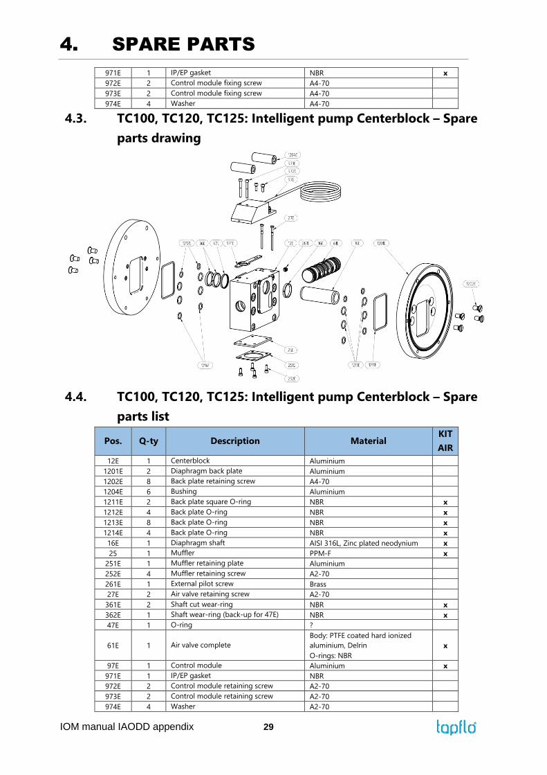
4.3. TC100, TC120, TC125: Intelligent pump Centerblock – Spare
parts drawing
4.4. TC100, TC120, TC125: Intelligent pump Centerblock – Spare
parts list
Pos. Q-ty Description Material KIT
AIR
12E 1 Centerblock Aluminium
1201E 2 Diaphragm back plate Aluminium
1202E 8 Back plate retaining screw A4-70
1204E 6 Bushing Aluminium
1211E 2 Back plate square O-ring NBR x
1212E 4 Back plate O-ring NBR x
1213E 8 Back plate O-ring NBR x
1214E 4 Back plate O-ring NBR x
16E 1 Diaphragm shaft AISI 316L, Zinc plated neodynium x
25 1 Muffler PPM-F x
251E 1 Muffler retaining plate Aluminium
252E 4 Muffler retaining screw A2-70
261E 1 External pilot screw Brass
27E 2 Air valve retaining screw A2-70
361E 2 Shaft cut wear-ring NBR x
362E 1 Shaft wear-ring (back-up for 47E) NBR x
47E 1 O-ring ?
61E 1 Air valve complete
Body: PTFE coated hard ionized
aluminium, Delrin
O-rings: NBR
x
97E 1 Control module Aluminium x
971E 1 IP/EP gasket NBR
972E 2 Control module retaining screw A2-70
973E 2 Control module retaining screw A2-70
974E 4 Washer A2-70

4. SPARE PARTS
IOM manual IAODD appendix 30

4. SPARE PARTS
IOM manual IAODD appendix 31
4.5. TC200, TC220, TC225: Intelligent pump Centerblock – Spare
parts drawing
4.6. TC200, TC220, TC225: Intelligent pump Centerblock – Spare
parts list
Pos. Q-ty Description Material KIT
AIR
12E 1 Centerblock Aluminium
1201E 2 Diaphragm back plate Aluminium
1202E 8 Back plate retaining screw A4-70
1204E 6 Bushing Aluminium
1211E 2 Back plate square O-ring NBR x
1212E 4 Back plate O-ring NBR x
1213E 8 Back plate O-ring NBR x
1214E 4 Back plate O-ring NBR x
16E 1 Diaphragm shaft AISI 316L, Zinc plated neodynium x
25 1 Muffler PPM-F x
251E 1 Muffler retaining plate Aluminium
252E 4 Muffler retaining screw A2-70
261E 1 External pilot screw Brass
27E 2 Air valve retaining screw A2-70
361E 2 Shaft cut wear-ring NBR x
362E 1 Shaft wear-ring (back-up for 47E) NBR x
47E 1 O-ring ?
61E 1 Air valve complete
Body: PTFE coated hard ionized
aluminium, Delrin
O-rings: NBR
x
97E 1 Control module Aluminium x
971E 1 IP/EP gasket NBR
972E 2 Control module retaining screw A2-70
973E 2 Control module retaining screw A2-70
974E 4 Washer A2-70

4. SPARE PARTS
IOM manual IAODD appendix 32
4.7. TC400, TC420, TC425: Intelligent pump Centerblock – Spare
parts drawing
4.8. TC400, TC420, TC425: Intelligent pump Centerblock – Spare
parts list
Pos. Q-ty Description Material KIT
AIR
12E 1 Centerblock Aluminium
1201E 2 Diaphragm back plate Aluminium
1202E 12 Back plate retaining screw A4-70
1203E 4 Back plate retaining screw A4-70
1204E 6 Bushing Aluminium
1211E 2 Back plate square O-ring NBR x
1212E 4 Back plate O-ring NBR x
1213E 8 Back plate O-ring NBR x
1214E 4 Back plate O-ring NBR x
16E 1 Diaphragm shaft AISI 316L, Zinc plated neodynium x
25 1 Muffler PPM-F x
251E 1 Muffler retaining plate Aluminium
252E 4 Muffler retaining screw A2-70
261E 1 External pilot screw Brass
27E 2 Air valve retaining screw A2-70
361E 2 Shaft cut wear-ring NBR x
362E 1 Shaft wear-ring (back-up for 47E) NBR x
47E 1 O-ring ?
61E 1 Air valve complete
Body: PTFE coated hard ionized
aluminium, Delrin
O-rings: NBR
x
97E 1 Control module Aluminium x
971E 1 IP/EP gasket NBR
972E 2 Control module retaining screw A2-70
973E 2 Control module retaining screw A2-70
974E 4 Washer A2-70

4. SPARE PARTS
IOM manual IAODD appendix 33
4.9. Stocking recommendation
Even at normal operation some details in the pump will be worn. In order to avoid expensive
breakdowns we recommend having a few spare parts in stock.
Depending on the severity of the operation and the importance of assuring continuous work
we offer three different spare part KITS, please check full PE & PTFE, Metal, Sanitary IOM
manual* for further instructions. Please keep in mind that IAODD pump KIT AIR differs from
standard PE & PTFE, Metal or Sanitary pump*.
NOTE! However control module [97E] is not a subject to wear, remember to replace it in case of
leakage through muffler.
*depends on the product series
T50, T70, T80
Pos. Description Q-ty
KIT AIR
16E Complete diaphragm shaft 1
18 O-ring set in/outlet 4
25 Muffler 1
61E Complete Air valve 1
971E IP/EP gasket 1
T100, T120, T125, T200, T220, T225, T400, T420, T425
Pos. Description Q-ty
KIT AIR
18 O-ring set in/outlet 4
16E Complete diaphragm shaft 1
1211E Back plate square O-ring 2
1212E Back plate O-ring 4
1213E Back plate O-ring 8
1214E Back plate O-ring 4
361E Shaft cut wear-ring
2
362E Shaft wear-ring (back-up for 36E)
1
25E Muffler 1
61E Complete Air valve 1
971E IP/EP gasket 1

5. WARRANTY
IOM manual IAODD appendix 34
5. WARRANTY
5.1. Warranty form
Company:
Telephone: Fax:
Address:
Country: Contact Name:
E-mail:
Delivery Date: Date of pump installation:
Pump type:
Serial No (see name plate or stamped on pump housing):
Description of the fault:
The installation:
Liquid:
Temperature [°C]: Viscosity [cPs]: Spec grav. [kg/m3]: pH-value:
Content of particles: %, of max size [mm]:
Flow [l/min]: Duty [h/day]: No of starts per day:
Discharge head [mWC]: Suction head / lift [m]:
Air pressure [bar]: Quality of the air (filter, micron, lubrication):
Other:
Place for sketch of installation:

5. WARRANTY
IOM manual IAODD appendix 35
5.2. Returning parts
When returning parts to Tapflo please follow this procedure:
Consult Tapflo for shipping instructions.
Cleanse or neutralize and rinse the part/pump. Make sure the part/pump is
completely empty from liquid.
Pack the return articles carefully to prevent any damage during transportation.
Goods will not be accepted unless the above procedure has been complied with.
5.3. Warranty
Tapflo warrants products under conditions as stated below for a period of not more than 5
years from installation and not more than 6 years from date of manufacturing.
1. The following terms and conditions apply to the sale of machinery, components and
related services and products, of Tapflo (hereinafter “the products”).
2. Tapflo (the manufacturer) warrants that:
a. its products are free of defects in material, design and workmanship at the time of
original purchase;
b. its products will function in accordance with Tapflo operative manuals; Tapflo does
not guarantee that the product will meet the precise needs of the Customer, except
for those purposes set out in any invitation to render documents or other documents
specifically made available to Tapflo before entering into this agreement;
c. high quality materials are used in the construction of the pumps and that machining
and assembly are carried out to the highest standards.
Except as expressly stated above, Tapflo makes no warranties, express or implied,
concerning the products, including all warranties of fitness for a particular purpose.
3. This warranty shall not be applicable in circumstances other than defects in material,
design, and workmanship. In particular warranty shall not cover the following:
a. Periodic checks, maintenance, repair and replacement of parts due to normal wear
and tear (seals, O-rings, rubber items, diaphragms, air valves etc..);
b. Damage to the product resulting from:
b.1. Tampering with, abuse or misuse, including but not limited to failure to use the
product for its normal purposes as stated at the time of purchase or in accordance
with Tapflo instructions for use and maintenance of the product, or the
installation or improper ventilation or use of the product in a manner inconsistent
with the technical or safety standard in force;
b.2. Repairs performed by non-skilled personnel or use of non-original Tapflo parts;

5. WARRANTY
IOM manual IAODD appendix 36
b.3. Accidents or any cause beyond the control of Tapflo, including but not limited
to lightning, water, fire, earthquake, and public disturbances, etc.;
4. The warrantee shall cover the replacement or repairing of any parts, which is documented
faulty due to construction or assembling, with new or repaired parts free of charges
delivered by Tapflo. Parts subjected to normal tear and wear shall not be covered by the
warranty. Tapflo shall decide as to whether the defective or faulty part shall be replaced
or repaired.
5. The warrantee of the products shall be valid for a period in accordance to the current law
from the date of delivery, under the condition that notice of the alleged defect to the
products or parts thereof be given to Tapflo in written within the mandatory term of 8
days from the discovery. Repair or replacement under the terms of this warranty shall not
give a right to an extension to, or a new commencement of, the period of warranty.
6. Repair or replacement under the terms of this warranty shall not give a right to an
extension to, or a new commencement of, the period of warranty. Repair or replacement
under the terms of this warranty may be fulfilled with functionally equivalent
reconditioned units. Tapflo qualified personnel shall be solely entitled to carry out repair
or replacement of faulty parts after careful examination of the pump. Replaced faulty parts
or components will become the property of Tapflo.
7. The products are built in accordance with standard CE normative and are tested (where
applicable) by Tapflo. Approval and tests by other control authority are for the customer’s
account. The products shall not be considered defective in materials, design or
workmanship if they need to be adapted, changed or adjusted to conform to national or
local technical or safety standards in force in any country other than that for which the
unit was originally designed and manufactured. This warranty shall not reimburse such
adaptations, changes or adjustments, or attempt to do so, whether properly performed
or not, nor any damage resulting from them, nor any adaptation, change or adjustments
to upgrade the products from their normal purpose as described in the products operative
manual without the prior written consent of Tapflo.
8. Installation, including electric and other connections to utility mains according to Tapflo
drawings, is for the cost and responsibility of the customer, unless otherwise agreed in
writing.
9. Tapflo will not be liable on any claim, whether in contact, tort, or otherwise, for any
indirect, special, incidental, or consequential damages, caused to the customer or to third
parties, including loss of profits, arising by any possible infringement of par. 3 above or
by the customer or third parties being in the impossibility of using the products.
Steady the above, Tapflo liability to the customer or third parties from any claim, whether in
contract, tort, or otherwise, shall be limited to the total amount paid by the customer for the
product that caused the damages.

TAPFLO AB
Sweden
Filaregatan 4 | S-442 34 Kungälv
Tel: +46 303 63390
Fax: +46 303 19916
E-mail addresses:
Commercial questions: [email protected]
Orders: [email protected]
Tech support: [email protected]
Tapflo products and services are available in 75 countries on 6 continents.
Tapflo is represented worldwide by own Tapflo Group Companies and carefully selected distributors assuring highest Tapflo service
quality for our customers’ convenience.
AUSTRALIA | AUSTRIA | AZERBAIJAN | BAHRAIN | BELARUS | BELGIUM | BOSNIA & HERZEGOVINA | BRAZIL | BULGARIA |
CANADA | CHILE | CHINA | COLOMBIA | CROATIA | CZECH REPUBLIC | DENMARK | ECUADOR | EGYPT | ESTONIA | FINLAND |
FRANCE | GREECE | GEORGIA | GERMANY | HONG-KONG | HUNGARY | ICELAND | INDIA | INDONESIA | IRAN | IRELAND | ISRAEL |
ITALY | JAPAN | JORDAN | KAZAKHSTAN | KUWAIT | LATVIA | LIBYA | LITHUANIA | MACEDONIA | MALAYSIA | MEXICO |
MONTENEGRO | MOROCCO | THE NETHERLANDS | NEW ZEALAND | NORWAY | POLAND | PORTUGAL | PHILIPPINES | QATAR |
ROMANIA | RUSSIA | SAUDI ARABIA | SERBIA | SINGAPORE | SLOVAKIA | SLOVENIA | SOUTH AFRICA | SOUTH KOREA | SPAIN |
SUDAN | SWEDEN | SWITZERLAND | SYRIA | TAIWAN | THAILAND | TURKEY | UKRAINE | UNITED ARAB EMIRATES |
UNITED KINGDOM | USA | UZBEKISTAN | VIETNAM
Tapflo Group Companies
Austria
Tapflo Austria
Tel: +43 732 27292910
Azerbaijan
Tapflo Azerbaijan LLC
Tel: +994 502660799
Baltic States
Tapflo Latvia
Tel: +371 67472205
Belarus
Tapflo Belarus
Tel: +375 17 3934609
Bulgaria
Tapflo EOOD
Tel: +359 (2) 974 18 54
Canada
Tapflo Canada
Tel: +1 514 813 5754
Croatia
Tapflo GmbH
Tel: +385 91 4884 666
Czech Republic
Tapflo s.r.o.
Tel: +420 513033924
China
Tapflo (Wuxi)
Tel: +86 510 8241 7602
Denmark
Tapflo Danmark
Tel: +45 36 454600
France
Tapflo France
Tel: +33 1 34 78 82 40
Georgia
Tapflo Georgia
Tel: +995 577 463010
India
Tapflo Fluid Handling India
Pvt Ltd
Tel: +91 20 65000215
Ireland
Tapflo Ireland Ltd
Tel: +353 1 2011911
Italy
Tapflo Italia
Tel: +39 0362307698
Japan
Tapflo Japan K.K.
Tel: +81-3-6240-3510
Kazakhstan
Tapflo Kazakstan
Tel: +7 727 3278347
Poland
Tapflo Sp. z o.o.
Tel: +48 58 530 42 00
Romania
S.C. Tapflo Rom. S.r.l.
Tel: +40 21 3451255
Russia
Tapflo Company
Tel: +7 495 232 18 28
Serbia
Tapflo d.o.o.
Tel: +381 21 44 58 08
Slovakia
Tapflo s.r.o.
Tel: +421 911 137 883
Slovenia
Tapflo GmbH
Tel: +386 68 613 474
Spain
Tapflo Iberica
Tel: +34 91 8093182
South Africa
Tapflo (Pty) Ltd
Tel: +27 31 701 5255
Turkey
Tapflo Makina Ltd
Tel: +90 216 467 33 11
Ukraine
TOB Tapflo
Tel: +380 44 222 68 44
Uzbekistan
Tapflo Uzbekistan
Tel.: +998 712340940
United Kingdom
Tapflo (UK) Ltd
Tel: +44 2380 252325