intelligent compact drive product manual
TRANSCRIPT

www.schneider-electric-motion.com0098
4411
1326
8, V
2.00
, 12.
2008
IclA N065Intelligent Compact DriveProduct manualV2.00, 12.2008

2 Intelligent Compact Drive
Important information IclA N065
0098
4411
1326
8, V
2.00
, 12.
2008
Important information
The drive systems described here are products for general use that con-form to the state of the art in technology and are designed to prevent any dangers. However, drives and drive controllers that are not specifically designed for safety functions are not approved for applications where the functioning of the drive could endanger persons. The possibility of unexpected or unbraked movements can never be totally excluded with-out additional safety equipment. For this reason personnel must never be in the danger zone of the drives unless additional suitable safety equipment prevents any personal danger. This applies to operation of the machine during production and also to all service and maintenance work on drives and the machine. The machine design must ensure per-sonal safety. Suitable measures for prevention of property damage are also required.
See safety section for additional critical instructions.
Not all product variants are available in all countries.Please consult the current catalogue for information on the availability of product variants.
We reserve the right to make changes during the course of technical de-velopments.
All details provided are technical data and not promised characteristics.
In general, product names must be considered to be trademarks of the respective owners, even if not specifically identified as such.

0098
4411
1326
8, V
2.00
, 12.
2008
IclA N065 Table of Contents
Intelligent Compact Drive 3
Table of Contents
Important information. . . . . . . . . . . . . . . . . . . . . . . . . . . . . . . . . 2
Table of Contents . . . . . . . . . . . . . . . . . . . . . . . . . . . . . . . . . . . . 3
Writing conventions and symbols. . . . . . . . . . . . . . . . . . . . . . . 7
1 Introduction . . . . . . . . . . . . . . . . . . . . . . . . . . . . . . . . . . . . . . . . . 9
1.1 About this manual . . . . . . . . . . . . . . . . . . . . . . . . . . . . . . 9
1.2 Scope of supply. . . . . . . . . . . . . . . . . . . . . . . . . . . . . . . . 9
1.3 Unit overview. . . . . . . . . . . . . . . . . . . . . . . . . . . . . . . . . 10
1.4 Components and interfaces . . . . . . . . . . . . . . . . . . . . . 111.4.1 Components . . . . . . . . . . . . . . . . . . . . . . . . . . . . . . . 111.4.2 gear . . . . . . . . . . . . . . . . . . . . . . . . . . . . . . . . . . . . . 121.4.3 Interfaces . . . . . . . . . . . . . . . . . . . . . . . . . . . . . . . . . 131.4.4 Parameters and operating mode . . . . . . . . . . . . . . . 13
1.5 Type code . . . . . . . . . . . . . . . . . . . . . . . . . . . . . . . . . . . 14
1.6 Documentation and literature references . . . . . . . . . . . 15
1.7 Directives and standards. . . . . . . . . . . . . . . . . . . . . . . . 16
1.8 Declaration of conformity. . . . . . . . . . . . . . . . . . . . . . . . 17
2 Safety . . . . . . . . . . . . . . . . . . . . . . . . . . . . . . . . . . . . . . . . . . . . . 19
2.1 Qualification of personnel . . . . . . . . . . . . . . . . . . . . . . . 19
2.2 Intended use . . . . . . . . . . . . . . . . . . . . . . . . . . . . . . . . . 19
2.3 Hazard categories . . . . . . . . . . . . . . . . . . . . . . . . . . . . . 20
2.4 General safety instructions . . . . . . . . . . . . . . . . . . . . . . 20
2.5 Monitoring functions . . . . . . . . . . . . . . . . . . . . . . . . . . . 22
3 Technical Data . . . . . . . . . . . . . . . . . . . . . . . . . . . . . . . . . . . . . . 23
3.1 Environmental conditions . . . . . . . . . . . . . . . . . . . . . . . 23
3.2 Electrical and mechanical data . . . . . . . . . . . . . . . . . . . 243.2.1 Degree of protection . . . . . . . . . . . . . . . . . . . . . . . . . 243.2.2 Service life . . . . . . . . . . . . . . . . . . . . . . . . . . . . . . . . 243.2.3 IclA N065 DC024 . . . . . . . . . . . . . . . . . . . . . . . . . . . 253.2.4 IclA N065 V - with spur wheel gearing . . . . . . . . . . . 273.2.5 IclA N065 U- with angled wormgear . . . . . . . . . . . . . 313.2.6 Electrical terminals . . . . . . . . . . . . . . . . . . . . . . . . . . 35
4 Installation . . . . . . . . . . . . . . . . . . . . . . . . . . . . . . . . . . . . . . . . . 37
4.1 Electromagnetic compatibility, EMC . . . . . . . . . . . . . . . 37
4.2 Mechanical installation . . . . . . . . . . . . . . . . . . . . . . . . . 394.2.1 Mounting. . . . . . . . . . . . . . . . . . . . . . . . . . . . . . . . . . 39

4 Intelligent Compact Drive
Table of Contents IclA N065
0098
4411
1326
8, V
2.00
, 12.
2008
4.3 Electrical installation . . . . . . . . . . . . . . . . . . . . . . . . . . . 414.3.1 Overview of all connections . . . . . . . . . . . . . . . . . . . 414.3.2 Equipotential bonding connection . . . . . . . . . . . . . . 424.3.3 Overview signal interface . . . . . . . . . . . . . . . . . . . . . 434.3.4 Supply voltage connection 24VDC . . . . . . . . . . . . . 444.3.5 Connection control inputs . . . . . . . . . . . . . . . . . . . . 464.3.6 Connection Enable. . . . . . . . . . . . . . . . . . . . . . . . . . 474.3.7 Fieldbus connection . . . . . . . . . . . . . . . . . . . . . . . . . 484.3.8 Connection Braking Resistor Controller. . . . . . . . . . 504.3.9 Checks . . . . . . . . . . . . . . . . . . . . . . . . . . . . . . . . . . . 51
5 Commissioning. . . . . . . . . . . . . . . . . . . . . . . . . . . . . . . . . . . . . . 53
5.1 General safety instructions . . . . . . . . . . . . . . . . . . . . . . 53
5.2 Commissioning procedure . . . . . . . . . . . . . . . . . . . . . . 55
5.3 Commissioning software ICCT . . . . . . . . . . . . . . . . . . . 565.3.1 Firmware update over fieldbus. . . . . . . . . . . . . . . . . 56
5.4 Difference between the controller objects of D065 and N065 . . . . . . . . . . . . . . . . . . . . . . . . . . . . . . 57
6 Operation. . . . . . . . . . . . . . . . . . . . . . . . . . . . . . . . . . . . . . . . . . . 59
6.1 Operating modes . . . . . . . . . . . . . . . . . . . . . . . . . . . . . 59
6.2 Functions . . . . . . . . . . . . . . . . . . . . . . . . . . . . . . . . . . . 60
6.3 Protection and monitoring functions . . . . . . . . . . . . . . . 616.3.1 Enable function . . . . . . . . . . . . . . . . . . . . . . . . . . . . 616.3.2 Monitoring functions of the motor controller. . . . . . . 62
7 Diagnostics and troubleshooting . . . . . . . . . . . . . . . . . . . . . . . 67
7.1 Fieldbus communication error diagnosis . . . . . . . . . . . 67
7.2 Error diagnosis over fieldbus . . . . . . . . . . . . . . . . . . . . 687.2.1 Message objects . . . . . . . . . . . . . . . . . . . . . . . . . . . 687.2.2 Messages on the device status . . . . . . . . . . . . . . . . 69
7.3 Error code table . . . . . . . . . . . . . . . . . . . . . . . . . . . . . . 74
8 Accessories and spare parts . . . . . . . . . . . . . . . . . . . . . . . . . . 77
8.1 Accessories . . . . . . . . . . . . . . . . . . . . . . . . . . . . . . . . . 77
9 Service, maintenance and disposal . . . . . . . . . . . . . . . . . . . . . 79
9.1 Service address . . . . . . . . . . . . . . . . . . . . . . . . . . . . . . 79
9.2 Maintenance . . . . . . . . . . . . . . . . . . . . . . . . . . . . . . . . . 79
9.3 Replacing units . . . . . . . . . . . . . . . . . . . . . . . . . . . . . . . 80
9.4 Shipping, storage, disposal. . . . . . . . . . . . . . . . . . . . . . 81
10 Glossary . . . . . . . . . . . . . . . . . . . . . . . . . . . . . . . . . . . . . . . . . . . 83
10.1 Units and conversion tables . . . . . . . . . . . . . . . . . . . . . 83

0098
4411
1326
8, V
2.00
, 12.
2008
IclA N065 Table of Contents
Intelligent Compact Drive 5
10.1.1 Length. . . . . . . . . . . . . . . . . . . . . . . . . . . . . . . . . . . . 8310.1.2 Mass . . . . . . . . . . . . . . . . . . . . . . . . . . . . . . . . . . . . . 8310.1.3 Force. . . . . . . . . . . . . . . . . . . . . . . . . . . . . . . . . . . . . 8310.1.4 Power . . . . . . . . . . . . . . . . . . . . . . . . . . . . . . . . . . . . 8310.1.5 Rotation . . . . . . . . . . . . . . . . . . . . . . . . . . . . . . . . . . 8410.1.6 Torque. . . . . . . . . . . . . . . . . . . . . . . . . . . . . . . . . . . . 8410.1.7 Moment of inertia . . . . . . . . . . . . . . . . . . . . . . . . . . . 8410.1.8 Temperature . . . . . . . . . . . . . . . . . . . . . . . . . . . . . . . 8410.1.9 Conductor cross section . . . . . . . . . . . . . . . . . . . . . . 84
10.2 Terms and Abbreviations. . . . . . . . . . . . . . . . . . . . . . . . 85
11 Index. . . . . . . . . . . . . . . . . . . . . . . . . . . . . . . . . . . . . . . . . . . . . . 87

6 Intelligent Compact Drive
Table of Contents IclA N065
0098
4411
1326
8, V
2.00
, 12.
2008

0098
4411
1326
8, V
2.00
, 12.
2008
IclA N065 Writing conventions and symbols
Intelligent Compact Drive 7
Writing conventions and symbols
Work steps If work steps must be carried out in sequence, they are shown as fol-lows:
� Special prerequisites for the following work steps
� Step 1
� Important response to this work step
� Step 2
If a response to a work step is specified, this will inform you that the step has been carried out correctly.
Unless otherwise stated, the individual instruction steps must be carried in the given sequence.
Lists Lists can be sorted alphanumerically or by priority. Lists are structured as follows:
• Point 1
• Point 2
– Subpoint to 2
– Subpoint to 2
• Point 3
Making work easier Information on making work easier can be found at this symbol:
This offers supplementary information on making work easier.See the chapter on safety for an explanation of the safety instructions.
Parameters Parameters are shown as follows:
Group.Name Index:Subindex

8 Intelligent Compact Drive
Writing conventions and symbols IclA N065
0098
4411
1326
8, V
2.00
, 12.
2008
0098
4411
1326
8, V
2.00
, 12.
2008
IclA N065 1 Introduction
Intelligent Compact Drive 9
1 Introduction
1.1 About this manual
This manual is applicable for all N065 standard models.
1.2 Scope of supply
� Check the parts supplied to make sure they are complete.
� Keep the original packaging in case it is necessary to return the compact drive to the manufacturer for repair.
Scope of supply The scope of supply includes:
Item Quan-tity
Designation
1 1 Compact drive IclA
For the exact unit type see the type code

10 Intelligent Compact Drive
1 Introduction IclA N065
0098
4411
1326
8, V
2.00
, 12.
2008
1.3 Unit overview
Intelligent compact drives IclA The IclA N065 DC024 intelligent compact drives are servo drives based on an electronically commutated three-phase synchronous motor, re-ferred to as a brushless DC motor and a block-commutated positioning controller. Power and control electronics with fieldbus terminal, motor, position sensor and gearing are integrated in the compact unit.
Figure 1.1 Unit overview
Area of application The compact drives are primarily designed for automatic positioning of format axes during setup of production machines or for profile position-ing of handling systems. The speed control operating mode is another area of application. This makes it easy to implement transport and me-tering functions on production machines.
Special features The name IclA stands for Integrated closed loop Actuator; actual and reference values are prepared in a closed control loop. Features of the compact drives are:
• compact construction
• low wiring requirements
• excellent reliability
• integrated positioning and speed control functions
• fieldbus communications interface
• high power density

0098
4411
1326
8, V
2.00
, 12.
2008
IclA N065 1 Introduction
Intelligent Compact Drive 11
1.4 Components and interfaces
Figure 1.2 Components and interfaces
The intelligent compact drive has the following in compact design:
• Brushless DC motor
• Position sensor
• Power and control electronics
• Interfaces for fieldbus communications, enable signal, manual mode and supply voltage.
• Gearing (optional)
1.4.1 Components
Motor The electronically commutated three-phase synchronous motor in com-bination with the rare-earth magnets offers outstanding power density and thus very high efficiency.
The motors have a high detent torque. This means that often the use of a holding brake can be dispensed with. Motors with 2 pole pairs have a higher detent torque and an internal resolution of 12 increments per rev-olution. The model with 4 pole pairs offers a lower detent torque and the internal resolution is 24 increments per revolution.
Position sensor The position sensor and controller electronics form a quasi-absolute value sensor. 5 hall sensors capture the actual position of the rotor where the number of pole pairs p = 2 with an absolute resolution per rev-olution of 12 increments and 24 increments with p = 4 pole pairs . A po-sition counter converts the actual position to a 32-bit absolute value. After positioning and before switching off the compact drive, the rotor po-sition and absolute value are saved in the internal memory. When the compact drive is switched on again, the quasi-absolute value sensor de-tects whether the motor axis has been mechanically shifted within a rev-olution and reports this as "Drive not referenced".
power electronics The power electronics converts the speed or position instructions from the control electronics for motor control. Monitoring functions continu-ously monitor for overvoltage and undervoltage and protect the compact drive from overload. The power electronics must be hardware-isolated via a second channel in parallel to the microcontroller. To ensure mini-
Motor
Position sensor
Power and controlelectronic
Power signal interface connection
Equipotientialbonding connection
Field bus connectionCAN out
Field bus connectionCAN in

12 Intelligent Compact Drive
1 Introduction IclA N065
0098
4411
1326
8, V
2.00
, 12.
2008
mum energy requirements, the electronics switch the power electronics off when the motor is at a standstill, the motor generates its detent torque from the permanent magnet field of the rotor.
1.4.2 gear
The case of the IclA N065 compact drives offers a selection of different types of gearing. Spur wheel gears and spur wheel angled wormgears are available
Spur wheel gears The IclA N065 V- compact drive has a 2, 3 or 4-ratio spur wheel gear. The gear teeth are metal and fitted with needle bearings. An important feature is the high power density, the low torsional backlash and the compact length of the drive with spur wheel gear.
Figure 1.3 Intelligent compact drive with spur wheel gear
Angled spur wheel wormgears The compact drive IclA N065 U- is equipped with a 1 or 2 speed spur wheel gear and a wormgear. The drives with angled spur wheel worm-gears have minimum torsional backlash and very high output torque. The variation of spur wheel and worm reduction can be set according to the application for high efficiency values up to self-locking. This type of gearing often proves suitable for implementation of compact and com-plex installation situations.
Figure 1.4 Intelligent compact drive with angled wormgear

0098
4411
1326
8, V
2.00
, 12.
2008
IclA N065 1 Introduction
Intelligent Compact Drive 13
1.4.3 Interfaces
Power/signal interface The compact drive is supplied with the operating voltage via the power interface.
The signal interface can be used in 2 different ways.
• The "Standard Interface" type offers the option of manually travers-ing the compact drive with the aid of configurable jog inputs.
• The "Sensor Interface" type makes homing of the drive easy with the evaluation of a reference switch and processing of two limit switches.
This also allows factory application-specific types to be generated, for which three signals are available as inputs or outputs.
Enable input The enable signal input works in parallel to the microcontroller and offers a signal path to activate the integrated enable function.
Connection for manual operation The compact drive can be moved manually in both directions with the in-put signals.
The compact drive must be referenced before manual operation.
Fieldbus connection The fieldbus interface is used for parameterisation and controlling the drive. This enables the drive to be integrated into a fieldbus network and controlled by a PLC.
Equipotential bonding connection We recommend connecting the compact drive and machine conduc-tively with the equipotential bonding connection to improve the EMC be-haviour.
1.4.4 Parameters and operating mode
Electronic Data Sheet The compact drive stores configuration and parameter data for gearbox, motor and power electronics in the electronic data sheet. The values are permanently stored in the drive when it delivered and be read out via the fieldbus.
Electronic log-books 2 electronic log-books record data from the movement mode. The fol-lowing are stored:
• operating time of the drive
• total time of drive in positioning mode
• number of positionings.
When the drive power is shut off the positioning controller uses the volt-age of the internal charging capacitors to transfer the movement data to a log-book. Every eight hours of total positioning time the data are also saved to the second log-book.
Application parameters Travel parameters and settings for the operating modes and functions of the compact drive are saved in a non-volatile data range and can be read and adjusted via the fieldbus. The compact drive is delivered with a factory setting. This setting remains saved in the event of power failure and can be reactivated by a fieldbus command.

14 Intelligent Compact Drive
1 Introduction IclA N065
0098
4411
1326
8, V
2.00
, 12.
2008
1.5 Type code
Example: IclA N06 5 / 2 DC024 V-007 K CAN 00
Product familyIntelligent Compact Drive IclA
IclA N06 5 / 2 DC024 V-007 K CAN 00
Size (flange)N06 = 66 mm
IclA N06 5 / 2 DC024 V-007 K CAN 00
Motor package length5 = 18 mm
IclA N06 5 / 2 DC024 V-007 K CAN 00
Not used IclA N06 5 / 2 DC024 V-007 K CAN 00
Number of pole pairs2
IclA N06 5 / 2 DC024 V-007 K CAN 00
Supply voltageDC024 = 24VDC
IclA N06 5 / 2 DC024 V-007 K CAN 00
Gearing type Step-up gear IclA N06 5 / 2 DC024 V-007 K CAN 00
O- without gearing O-000
V - with spur wheel gears 430:63160:9 75:2 490:9 3675:32
V-007V-018V-038V-054V-118
U - with angled wormgear 525:22 1715:32 735:8 3675:32
U-024U-054U-092U-115
Shaft type R = round, smooth shaft K = parallel key (only with spur wheel gears)F = D-shaped shaft (only with spur wheel gears)
IclA N06 5 / 2 DC024 V-007 K CAN 00
Communication interfaceCAN = CANopen
IclA N06 5 / 2 DC024 V-007 K CAN 00
Reserve00
IclA N06 5 / 2 DC024 V-007 K CAN 00

0098
4411
1326
8, V
2.00
, 12.
2008
IclA N065 1 Introduction
Intelligent Compact Drive 15
1.6 Documentation and literature references
The following User's manuals are supplied with this drive system:
• Product manual, describes the technical data, installation, com-missioning and all operating modes and operating functions.
• Fieldbus manual, important description of integrating the product into a fieldbus.
Source product manuals The current product manuals are available for download from the Inter-net.http://www.schneider-electric-motion.com
Additional literature We recommend the following literature for more in-depth information:
• Ellis, George: Control System Design Guide. Academic Press
• Kuo, Benjamin; Golnaraghi, Farid: Automatic Control Systems. John Wiley & Sons
16 Intelligent Compact Drive
1 Introduction IclA N065
0098
4411
1326
8, V
2.00
, 12.
2008
1.7 Directives and standards
CE mark With the declaration of conformity and the CE mark on the product the manufacturer certifies that the product complies with the requirements of all relevant EC directives.
EC Machine Directive The drive systems described here are not machines as defined by the EC Machine Directive (98/37/EEC) but components for installation in machines. They do not have moving parts designed for specific pur-poses. However, they can be components of a machine or system.
The manufacturer must certify that the complete system conforms to the machine directive with the CE mark.
EC EMC Directive The EC Electromagnetic Compatibility Directives (89/336/EEC) applies to products that cause electromagnetic interference or whose operation may be be adversely affected by electromagnetic interference.
Conformity with the EMC Directive can only be expected of drive sys-tems after correct installation in the machine. The information on ensur-ing electromagnetic compatibility given in the chapter on "Installation" must be followed to ensure that the drive system in the machine or sys-tem is EMC-compatible and that the product can legally be operated.
EC Low-Voltage Directive The EC Low Voltage Directive (73/23/EEC) is not applicable to the com-pact drive, because it is operated with CD current under 50 V.
Declaration of conformity The declaration of conformity certifies that the drive system complies with the specific EC directive.
Standards for safe operation EN 50178: Fitting power systems with electronic equipment
IEC 60204-1: Electrical equipment of machines, General requirements
IEC 60034-ff: Rotating electrical machines
IEC 61800-1: Variable-speed electrical drives
Standards for compliance withenvironmental conditions
IEC 60068-2-ff: Environmental tests
Standards for compliance with EMClimit values
IEC 61800-3: Variable-speed electrical drives
0098
4411
1326
8, V
2.00
, 12.
2008
IclA N065 1 Introduction
Intelligent Compact Drive 17
1.8 Declaration of conformity
SCHNEIDER ELECTRIC MOTION DEUTSCHLAND GmbH & Co. KG Breslauer Str. 7 D-77933 Lahr
EC DECLARATION OF CONFORMITY
YEAR 2008
according to EC Directive Machinery 98/37/EC according to EC Directive EMC 2004/108/EC according to EC Directive Low Voltage 2006/95/EC
We declare that the products listed below meet the requirements of the mentioned EC Directives with respect to design, construction and version distributed by us. This declaration becomes invalid with any modification on the products not authorized by us.
Designation: Intelligent compact drive
Type: N065
Product number: 00180012xxxxx
Applied harmonized standards, especially:
EN 61800-3:2004, second environment
Applied national standards and technical specifications, especially:
Product documentation
Company stamp: Date/Signature: 28 November 2008 Name/Department: Wolfgang Brandstätter/Development
IclA

18 Intelligent Compact Drive
1 Introduction IclA N065
0098
4411
1326
8, V
2.00
, 12.
2008
0098
4411
1326
8, V
2.00
, 12.
2008
IclA N065 2 Safety
Intelligent Compact Drive 19
2 Safety
2.1 Qualification of personnel
Only technicians who are familiar with and understand the contents of this manual and the other relevant manuals are authorised to work on and with this drive system. The technicians must be able to detect po-tential dangers that may be caused by setting parameters, changing pa-rameter values and generally by the mechanical, electrical and electronic equipment.
The technicians must have sufficient technical training, knowledge and experience to recognise and avoid dangers.
The technicians must be familiar with the relevant standards, regulations and safety regulations that must be observed when working on the drive system.
2.2 Intended use
The compact drive is a variable speed drive with a permanent-field elec-tronically commutated motor, integrated control electronics and optional integrated gearing.
The drive is an OEM component and should be used in machines and systems in the configuration described.
The drive systems described here are products for general use that con-form to the state of the art in technology and are designed to prevent any dangers. However, drives and drive controllers that are not specifically designed for safety functions are not approved for applications where the functioning of the drive could endanger persons. The possibility of unexpected or unbraked movements can never be totally excluded with-out additional safety equipment. For this reason personnel must never be in the danger zone of the drives unless additional suitable safety equipment prevents any personal danger. This applies to operation of the machine during production and also to all service and maintenance work on drives and the machine. The machine design must ensure per-sonal safety. Suitable measures for prevention of property damage are also required.
In the system configuration described the drive systems must be used in industrial applications only and must have a fixed connection only.
In all cases the applicable safety regulations and the specified operating conditions, such as environmental conditions and specified technical data, must be observed.
The drive system must not be commissioned and operated until com-pletion of installation in accordance with the EMC regulations and the specifications in this manual.
To prevent personal injury and damage to property damaged drive sys-tems must not be installed or operated.
Changes and modifications of the drive systems are not permitted and if made all no warranty and liability will be accepted.

20 Intelligent Compact Drive
2 Safety IclA N065
0098
4411
1326
8, V
2.00
, 12.
2008
The drive system must be operated only with the specified wiring and approved accessories. In general, use only original accessories and spare parts.
The drive systems must not be operated in an environment subject to explosion hazard (ex area).
2.3 Hazard categories
Safety notes and general information are indicated by hazard messages in the manual. In addition there are symbols and instructions affixed to the product that warn of possible hazards and help to operate the prod-uct safely.
Depending on the seriousness of the hazard, the messages are divided into three hazard categories.
2.4 General safety instructions
@ DANGERDANGER indicates an imminently hazardous situation, which, if not avoided, will result in death, serious injury, or equipment damage.
@ WARNINGWARNING indicates a potentially hazardous situation, which, if not avoided, can result in death, serious injury, or equipment damage.
@ CAUTIONCAUTION indicates a potentially hazardous situation, which, if not avoided, can result in injury or equipment damage.
@ DANGERMotor out of view
When the system is started the drives are generally out of the opera-tor's view and cannot be visually monitored.
• Only start the system if there are no persons in the operating zone of the moving components and the system can be operated safely.
Failure to follow these instructions will result in death or serious injury.

0098
4411
1326
8, V
2.00
, 12.
2008
IclA N065 2 Safety
Intelligent Compact Drive 21
@ WARNINGLoss of control
• Observe the accident prevention regulations. (For USA see also NEMA ICS1.1 and NEMA ICS7.1)
• The system manufacturer must take the potential error possibili-ties of the signals and the critical functions into account to ensure a safe status during and after errors. Some examples are: emer-gency stop, final position limitation, power failure and restart.
• The assessment of error possibilities must also include unex-pected delays and the failure of signals or functions.
• Suitable redundant control paths must be in place for dangerous functions.
• Check that measures taken are effective.
Failure to follow these instructions can result in death or serious injury.

22 Intelligent Compact Drive
2 Safety IclA N065
0098
4411
1326
8, V
2.00
, 12.
2008
2.5 Monitoring functions
The monitoring functions in the product protect the system and reduce the risks involved in a system malfunction. These monitoring functions are not sufficient for personal protection.The following errors and limit values can be monitored:
Monitoring Task Protective function
Data link Error response in event of connection break Functional safety and system protec-tion
Limit switch signals Monitoring of permissible area of travel System protection
Motor overload Monitoring for excessively high current in the motor phases Functional safety and device protec-tion
Overvoltage and under-voltage
Monitoring for overvoltage and undervoltage of the power supply Functional safety and device protec-tion
Overtemperature Monitoring device for overtemperature Device protection
I2t Limit Power limitation in event of overloading Device protection

0098
4411
1326
8, V
2.00
, 12.
2008
IclA N065 3 Technical Data
Intelligent Compact Drive 23
3 Technical Data
3.1 Environmental conditions
When considering the ambient temperature a distinction is made be-tween the permissible temperatures during operation and the permissi-ble storage and transport temperature.
ambient operating temperature The maximum permissible ambient air temperature during operation de-pends on the clearance between the units and the required output. The relevant requirements in the chapter on installation are also very impor-tant.
Ambient climate for transport andstorage
The environment during transport and storage must be dry and dust-free. The maximum oscillation and shock stress must be within the spec-ified limits. The bearing and transport temperature must remain within the specified range.
Relative humidity The relative humidity is allowed as follows:
Installation height
Oscillations and shocks
Ambient temperature without power reduction
[°C] +5 ... +40class 3K3, DIN EN 60721-3-3
Storage temperature [°C] -25 ... +55class 1K4, DIN EN 60721-3-1
Transport temperature [°C] -25 ... +70class 2K3, DIN EN 60721-3-2
Operation [%] 5 ... 85class 3K3, DIN EN 60721-3-3
Storage [%] 5 ... 95class 1K3, DIN EN 60721-3-1
Installation height without power reduction
[m] < 1000 m above sea level
Oscillations, sinusoidal in accordance with IEC/EN 60068-2-60.35 mm (from 10Hz ... 60Hz)50 m/s2 (from 60Hz ... 300Hz)
Shocks, semisinusoidal in accordance with IEC/EN 60068-2-27300 m/s2 (for 18 ms)
24 Intelligent Compact Drive
3 Technical Data IclA N065
0098
4411
1326
8, V
2.00
, 12.
2008
3.2 Electrical and mechanical data
3.2.1 Degree of protection
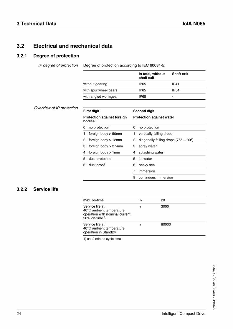
IP degree of protection Degree of protection according to IEC 60034-5.
Overview of IP protection
3.2.2 Service life
In total, without shaft exit
Shaft exit
without gearing IP65 IP41
with spur wheel gears IP65 IP54
with angled wormgear IP65 -
First digit Second digit
Protection against foreign bodies
Protection against water
0 no protection 0 no protection
1 foreign body > 50mm 1 vertically falling drops
2 foreign body > 12mm 2 diagonally falling drops (75° ... 90°)
3 foreign body > 2.5mm 3 spray water
4 foreign body > 1mm 4 splashing water
5 dust-protected 5 jet water
6 dust-proof 6 heavy sea
7 immersion
8 continuous immersion
max. on-time % 20
Service life at:40°C ambient temperatureoperation with nominal current20% on-time 1)
1) ca. 2 minute cycle time
h 3000
Service life at:40°C ambient temperatureoperation in StandBy
h 80000

0098
4411
1326
8, V
2.00
, 12.
2008
IclA N065 3 Technical Data
Intelligent Compact Drive 25
3.2.3 IclA N065 DC024
Dimensions
Figure 3.1 Dimensions without gearing
Design data
R7
A
81.1
14
17.5
6
4.3
□65
25
j6Ø8
Ø4.3pass hole 4 x h8 (2 high)Ø40centring
Size Unit
Nominal voltage UDC V 24
Number of pole pairs P 2 4
Rated speed nN rpm 4350
Nominal current IN DC A 3.79
Ready-for-operation current I0 A 0.09
max. Phase current î A 6.0
Torque constant kM Nm/A 0.036
Nominal output PN W 71
Nominal motor torque MN Nm 0.155
Starting torque Mmax Nm 0.22
Detent torque MS Nm 0.08 0.015
Moment of inertia JR g cm² 151
Min. speed 1) nmin inc./s1/min
60300
3075
max. Speed nmax 1/min 5000
Positioning resolution Inc./rev 12 24
Positioning resolution ° 30 15
Positioning accuracy Inc. ±1

26 Intelligent Compact Drive
3 Technical Data IclA N065
0098
4411
1326
8, V
2.00
, 12.
2008
Characteristic curves
Figure 3.2 Torque and flow characteristics IclA N065 DC024
Mass m kg 0.8
1) from software version V1.015
Shaft load
max. radial force 1)
1) point of attack of radial shaft load: 12.5 mm distance from flange
N 80
max. axial force pull N 30
Nominal bearing lifetime L10h2)
2) operating hours at a probability of failure of 10%
h 20000
Size Unit
0 1000 2000 3000 4000 5000
0,00
0,05
0,10
0,15
0,20
0,25
torq
ue [N
m]
motor speed [rpm]
0
1
2
3
4
5
3 A
5 A
6 A
c
onsum
ption c
urr
ent [A
]

0098
4411
1326
8, V
2.00
, 12.
2008
IclA N065 3 Technical Data
Intelligent Compact Drive 27
3.2.4 IclA N065 V - with spur wheel gearing
Dimensions
Figure 3.3 Dimensions with spur wheel gear
Design data
A
Ø3x3x16 10 h8fit-in key DIN 6885
centringØ16 h8 (4 high)
R7
1313
4 x pass hole Ø4.3
131.6
17.5
4.314
6
Size Unit V-007 V-018 V-038 V-054 V-115
Nominal voltage UDC V 24 24 24 24 24
Gear speeds nG 2 3 3 4 4
Ratio I 430: 63 160: 9 75: 2 490: 9 3675: 32
Number of pole pairs P 2 4 2 4 2 4 2 4 2 4
Nominal speed 1) nN rpm 4000 4000 4000 4000 4000
Nominal current IN DC A 4.43 4.43 4.43 4.43 3.16
Ready-for-operation cur-rent
I0 A 0.09 0.09 0.09 0.09 0.09
max. Phase current î A 6.0 6.0 6.0 6.0 4.5
Torque constant 1) kM Nm/A 0.036 0.036 0.036 0.036 0.036
Gear efficiency ηG 0.90 0.86 0.86 0.81 0.81
Nominal output PN W 68 64 64 61 45
Nominal output torque 2) MN Nm 1.1 2.7 5.8 7.9 12.3
Starting torque 2) Mmax Nm 1.3 3.3 6.9 9.6 15.2
Nominal output speed 2) nN rpm 586 225 107 73 35
Detent torque MS Nm 0.5 0.1 1.3 0.3 2.8 0.6 4.1 0.8 8.6 1.7

28 Intelligent Compact Drive
3 Technical Data IclA N065
0098
4411
1326
8, V
2.00
, 12.
2008
Characteristic curves
Figure 3.4 Torque and flow characteristics IclA N065 DC024 V-007
Moment of inertia 1) JR g cm² 151 151 151 151 151
Moment of inertia 2) JR kg m² 0.0007 0.0048 0.0212 0.0448 0.1992
Min. speed 2) 3) nmin 1/min 44 11 16.9 4.2 8 2 5.5 1.4 2.6 0.7
max. Speed 2) nmax 1/min 733 281 133 92 44
Torsional play 2) ° ≤ 1.5 ≤ 1.0 ≤ 1.0 ≤ 1.0 ≤ 1.0
Positioning resolution 1) Inc./rev 12 24 12 24 12 24 12 24 12 24
Positioning resolution 2) ° 4.40 2.20 1.69 0.84 0.80 0.40 0.55 0.28 0.26 0.13
Positioning accuracy 1) Inc. ±1 ±1 ±1 ±1 ±1
Mass m kg 1.1 1.2 1.2 1.2 1.2
1) with reference to motor shaft2) with reference to gearing output shaft3) From software version V1.015
Size Unit V-007 V-018 V-038 V-054 V-115
V-007 V-018 V-038 V-054 V-115
Shaft load (short-time operation)
max. radial force 1) N 200 200 200 200 200
max. axial force N 80 80 80 80 80
Nominal service life L10h 2) h 2500 2500 2500 2500 2500
Shaft load (continuous operation)
max. radial force 1) N 200 200 200 200 200
max. axial force N 10 10 10 10 10
Nominal service life L10h2) h 15000 15000 15000 15000 15000
1) point of attack of radial shaft load: 12.5 mm distance from flange2) operating hours at a probability of failure of 10%
0 1000 2000 3000 4000 5000
0,0
0,4
0,8
1,2
1,6
2,0
0,0 146,5 293,0 439,6 586,1 732,6
0
1
2
3
4
5
output speed [rpm]
torq
ue [N
m]
motor speed [rpm]
c
onsum
ption c
urr
ent [A
]

0098
4411
1326
8, V
2.00
, 12.
2008
IclA N065 3 Technical Data
Intelligent Compact Drive 29
Figure 3.5 Torque and flow characteristics IclA N065 DC024 V-018
Figure 3.6 Torque and flow characteristics IclA N065 DC024 V-038
0 1000 2000 3000 4000 5000
0,0
0,8
1,6
2,4
3,2
4,0
0,0 56,2 112,5 168,7 225,0 281,2
0
1
2
3
4
5
output speed [rpm]
torq
ue [N
m]
motor speed [rpm]
c
onsum
ption c
urr
ent [A
]
0 1000 2000 3000 4000 5000
0,0
1,6
3,2
4,8
6,4
8,0
0,0 26,7 53,3 80,0 106,7 133,3
0
1
2
3
4
5
output speed [rpm]
torq
ue [N
m]
motor speed [rpm]
c
onsum
ption c
urr
ent [A
]

30 Intelligent Compact Drive
3 Technical Data IclA N065
0098
4411
1326
8, V
2.00
, 12.
2008
Figure 3.7 Torque and flow characteristics IclA N065 DC024 V-054
Figure 3.8 Torque and flow characteristics IclA N065 DC024 V-115
0 1000 2000 3000 4000 5000
0,0
2,5
5,0
7,5
10,0
12,5
0,0 18,4 36,7 55,1 73,5 91,8
0
1
2
3
4
5
output speed [rpm]
torq
ue [N
m]
motor speed [rpm]
c
onsum
ption c
urr
ent [A
]
0 1000 2000 3000 4000 5000
0,0
4,0
8,0
12,0
16,0
20,0
0,0 8,7 17,4 26,1 34,8 43,5
0
1
2
3
4
5
output speed [rpm]
torq
ue [N
m]
motor speed [rpm]
c
onsum
ption c
urr
ent [A
]

0098
4411
1326
8, V
2.00
, 12.
2008
IclA N065 3 Technical Data
Intelligent Compact Drive 31
3.2.5 IclA N065 U- with angled wormgear
Dimensions
Figure 3.9 Dimensions with angled wormgear
Design data
2
28
36
34
34
A46.9
4 P9
R32
R 9
8h8
Ø46pitch circle-Ø
centringØ36 h8 (3,5 high)
Ø12 F8
lock againstrotation
34
2 x pass hole Ø5.3
6 x tappedblind holes
self-furrowingscrews M3
DIN 7500 (10 deep)
4.3
17.5 14
184.3139.381.6
�65
50.6
14.595
13.8
14.595
Size Unit U-024 U-054 U-092 U-115
Nominal voltage UDC V 24 24 24 24
Gear speeds nG 2 3 3 3
Ratio I 525: 22 1715: 32 735: 8 3675: 32
Number of pole pairs P 2 4 2 4 2 4 2 4
Nominal speed 1) nN rpm 4000 4000 4000 4000
Nominal current IN DC A 4.43 4.43 4.43 4.43
Ready-for-operation current I0 A 0.09 0.09 0.09 0.09
max. Phase current î A 6.0 6.0 6.0 6.0
Torque constant 1) kM Nm/A 0.036 0.036 0.036 0.036
Gear efficiency ηG 0.61 0.62 0.56 0.51

32 Intelligent Compact Drive
3 Technical Data IclA N065
0098
4411
1326
8, V
2.00
, 12.
2008
Characteristic curves
Figure 3.10 Torque and flow characteristics IclA N065 DC024 U-024
Nominal output PN W 46 47 42 39
Nominal output torque 2) MN Nm 2.6 6.0 9.2 10.6
Starting torque 2) Mmax Nm 2.2 5.0 7.8 8.9
Nominal output speed 2) nN rpm 168 75 44 35
Detent torque MS Nm 2.9 0.6 6.5 1.3 12.3 2.5 16.7 3.3
Moment of inertia 1) JR g cm² 165 150 150 150
Moment of inertia 2) JR kg m² 0.009 0.043 0.127 0.198
Min. speed 2) 3) nmax 1/min 12.6 3.1 5.6 1.4 3.3 0.8 2.6 0.7
max. Speed 2) nmax 1/min 189 93 54 44
Torsional play 2) ° ≤ 1.5 ≤ 1.0 ≤ 1.0 ≤ 1.0
Positioning resolution 1) Inc./rev 12 24 12 24 12 24 12 24
Positioning resolution 2) ° 1.26 0.63 0.56 0.28 0.33 0.16 0.26 0.13
Positioning accuracy 1) Inc. ±1 ±1 ±1 ±1
Mass m kg 1.7 1.7 1.7 1.7
1) with reference to motor shaft2) with reference to gear output shaft3) from software version V1.015
Size Unit U-024 U-054 U-092 U-115
Shaft load U-024 U-054 U-092 U-115
max. radial force N 200 200 200 200
max. axial force N 80 80 80 80
Nominal service life L10h1) h 9000 6000 6000 3000
1) operating hours at a probability of failure of 10%
0 1000 2000 3000 4000 5000
0,0
0,8
1,6
2,4
3,2
4,0
0,0 43,5 87,0 130,4 173,9 217,4
0
1
2
3
4
5
output speed [rpm]
torq
ue [N
m]
motor speed [rpm]
c
onsum
ption c
urr
ent [A
]

0098
4411
1326
8, V
2.00
, 12.
2008
IclA N065 3 Technical Data
Intelligent Compact Drive 33
Figure 3.11 Torque and flow characteristics IclA N065 DC024 U-054
Figure 3.12 Torque and flow characteristics IclA N065 DC024 U-092
0 1000 2000 3000 4000 5000
0,0
2,0
4,0
6,0
8,0
10,0
0,0 18,4 36,7 55,1 73,5 91,8
0
1
2
3
4
5
output speed [rpm]
torq
ue [N
m]
motor speed [rpm]
c
onsum
ption c
urr
ent [A
]
0 1000 2000 3000 4000 5000
0,0
2,5
5,0
7,5
10,0
12,5
0,0 10,9 21,7 32,6 43,5 54,3
0
1
2
3
4
5
output speed [rpm]
torq
ue [N
m]
motor speed [rpm]
c
onsum
ption c
urr
ent [A
]

34 Intelligent Compact Drive
3 Technical Data IclA N065
0098
4411
1326
8, V
2.00
, 12.
2008
Figure 3.13 Torque and flow characteristics IclA N065 DC024 U-115
0 1000 2000 3000 4000 5000
0,0
3,0
6,0
9,0
12,0
15,0
0,0 8,7 17,4 26,1 34,8 43,5
0
1
2
3
4
5
output speed [rpm]
torq
ue [N
m]
motor speed [rpm]
c
onsum
ption c
urr
ent [A
]

0098
4411
1326
8, V
2.00
, 12.
2008
IclA N065 3 Technical Data
Intelligent Compact Drive 35
3.2.6 Electrical terminals
Power supply
reverse-polarity-protected
Nominal power supply range Vdc 19.2... 28.8 (permissible operating range)
Ripple at nominal voltage V ≤ 3.6
Inrush current A Load current for DC bus capacity (500 µF)
24V signal interface
4 signal inputs, 0VDC internally connected with 0VDC supply voltage, reverse-polarity-protected
Permissible low level V / mA ≤4.5 / ≤0.7
Permissible high level V / mA ≥15 / ≥2
Admissible voltage range V 0...30
Debounce time of signal inputs ms 50 (in manual operation) Without debounce (reference movement switch and limit position sensors)
CAN fieldbus interface
CANIn/CANOut - topology
Signal inputs/outputs according to ISO 11898, no galvanic isolation
Transmission rate kBaud 10, 20, 50, 100, 125, 250, 500, 800, 1000
Transmission protocol CANopen Communication profile: DS301 V4.02
Device Profile: DSP 402 V2.0

36 Intelligent Compact Drive
3 Technical Data IclA N065
0098
4411
1326
8, V
2.00
, 12.
2008

0098
4411
1326
8, V
2.00
, 12.
2008
IclA N065 4 Installation
Intelligent Compact Drive 37
4 Installation
4.1 Electromagnetic compatibility, EMC
The drive and the system are subject to electromagnetic interference. If suitable precautions are not taken, the interference will affect the signals from the control lines and system parts and adversely affect the operat-ing reliability of the system.
Before operation the electromagnetic compatibility of the system must be checked and assured. The drive system conforms to the require-ments of the EC directives on EMC immunity to interference under IEC 61800-3 for the second environment where the following actions are taken into account during installation.
To maintain the limit values for the EMC interference resistance and in-terference radiation the drive must be earthed. It can be grounded from the motor flange or the electronics housing. This is generally done by bolting the motor to an electrically conductive and earthed machine component for sufficient earthing of the drive.
@ WARNINGInterference with signals and devices
Distorted signals can cause unpredictable device responses.
• Install the wiring in accordance with the EMC requirements.
• Check compliance with the EMC requirements, particularly in an environment subject to strong interference.
Failure to follow these instructions can result in death, serious injury or equipment damage.
@ WARNINGDanger from interference with signals and devices
This is a product with restricted availability under IEC 61800-3. It may cause radio interference in the domestic environment.
• Check compliance with the EMC requirements, particularly in an environment subject to strong interference.
Failure to follow these instructions can result in death, serious injury or equipment damage.

38 Intelligent Compact Drive
4 Installation IclA N065
0098
4411
1326
8, V
2.00
, 12.
2008
Table 4.1 EMC measures
Equipotential bonding conductors The shields are connected at both ends for fault protection. Potential dif-ferences can result in excessive currents on the shield and must be pre-vented by equipotential bonding conductor cables.
If lines over 100 m are approved, the following applies: up to 200 m length a cable cross section of 16 mm2 is sufficient, for greater lengths a cable cross section of 20 mm2 is required.
EMC measures Effect
Keep wiring as short as possible. Do not install "safety loops", short cables from the star point in the switch cabinet to outlying earth connection.
Avoidance of capacitive and inductive interference injec-tion
The electronics case is electrically con-nected to the motor. Earthing drive through the motor flange. If this is not possible, pro-vide additional earth wire connected to the plug cover lid or with a cable clip to the flange. Note that in this case the drive will not be earthed when the cover is removed.
Reduce emissions, increase interference resistance
Earth shields on digital signal lines over a wide area at both ends or via conductive plug housing.
Preventing interference on control cables, reduction of emissions
Connect large surface areas of cable shields, use cable clamps and tapes
Reduction of emissions.

0098
4411
1326
8, V
2.00
, 12.
2008
IclA N065 4 Installation
Intelligent Compact Drive 39
4.2 Mechanical installation
4.2.1 Mounting
� Check the drive for externally visible damage such as faulty terminal clamps or damage to the housing. Do not install damaged devices.
The compact drive must be fixed with four bolts.
� Install the drive on a flat horizontal surface to prevent transmission of mechanical tension to the housing.
� Tighten the flange bolts with spring washers to prevent twisting.
The compact drive becomes hot during operation. Do not enclose the drive in a heatproof enclosure.
Figure 4.1 Mechanical load
Load Support a flanged spindle or shaft with suitable bearings if it is subject to high transverse or axial forces.
@ CAUTIONFailure of the drive by mechanical damage
If the maximum allowable forces on the shaft are exceeded, this will result in accelerated bearing wear or shaft breakage.
• Do not exceed the maximum allowable axial and radial forces.
• Protect the shaft against impact.
• Do not exceed the maximum allowable axial force even when pressing on output components.
Failure to follow these instructions can result in injury or equip-ment damage.
4 x M4with spring ring

40 Intelligent Compact Drive
4 Installation IclA N065
0098
4411
1326
8, V
2.00
, 12.
2008
Figure 4.2 Mechanical load
The maximum permissible stress for the various unit types are listed in 3.2 "Electrical and mechanical data".
Differentiation by protection classes If the shaft exit is dust and waterproof, the drive can be installed in an en-vironment corresponding to IP65.
FA
FQ

0098
4411
1326
8, V
2.00
, 12.
2008
IclA N065 4 Installation
Intelligent Compact Drive 41
4.3 Electrical installation
4.3.1 Overview of all connections
The following figure shows all connections in overview.
Figure 4.3 Unit connections
• Signal interface, connection for:
– Supply voltage
– Control signals (manual operation)
– Limit switch signals (fieldbus operation)
– Enable signal
– Braking Resistor Controller
• Equipotential bonding for grounding via PE busbar
• CAN fieldbus interface
Connect prepared and tested cables only.
@ WARNINGInterference with signals and devices
Distorted signals can cause unpredictable device responses.
• Install the wiring in accordance with the EMC requirements.
• Check compliance with the EMC requirements, particularly in an environment subject to strong interference.
Failure to follow these instructions can result in death, serious injury or equipment damage.
CAN out
CAN in
Power signal interface connection
connection
Equipotiential bonding
Field bus connection
Field bus connection

42 Intelligent Compact Drive
4 Installation IclA N065
0098
4411
1326
8, V
2.00
, 12.
2008
4.3.2 Equipotential bonding connection
The shields are connected at both ends for fault protection. Potential dif-ferences can result in excessive currents on the shield and must be pre-vented by equipotential bonding conductor cables.
The compact drive is connected to ground potential via equipotential bonding.
Figure 4.4 Equipotential bonding connection
Cable specifications If lines over 100 m are approved, the following applies: up to 200 m length a cable cross section of 16 mm2 is sufficient, for greater lengths a cable cross section of 20 mm2 is required.
Connecting cable � Fasten the equipotential bonding cable to the equipotential bonding connection of the compact drive with the screw.
The included M4x6 fillister head screw is self-locking.
Use the safety contact cable with cable lug, ∅4.5mm.
� Connect the bonding conductor to the central PE busbar or the cen-tral protective conductor terminal of the machine.

0098
4411
1326
8, V
2.00
, 12.
2008
IclA N065 4 Installation
Intelligent Compact Drive 43
4.3.3 Overview signal interface
The signal interface is a 9-pin Sub-D plug with UNC fasteners, degree of protection IP65.
Figure 4.5 Sub-D connector
Connectors for manufacture of a connector cable for environmental con-ditions corresponding to IP65 can be found in the accessories list in chapter 8 "Accessories and spare parts".
@ WARNINGRisk of injury or damage to the drive
With a short circuit of the signal CHOPPER against 0VDC the supply voltage is also short-circuited against 0VDC.
• Run the wiring as specified.
Failure to follow these instructions can result in death, serious injury or equipment damage.
1 MAN_0V / REF
5 CHOPPER
2 ENABLE3 MAN_N / LIM_N4 MAN_P / LIM_P
60VDC70VDC824VDC924VDC
Pin Signal Description I/O
1 MAN_0V
REF
Reference potential at MAN_P and MAN_N
Reference switch (normally open contact 1))
1) at factory setting
-
I
2 ENABLE Activating and deactivating the power amplifier I
3 MAN_N
LIM_N
Jog counterclockwise rotation
Negative limit switch (normally closed contact 1))
I
I
4 MAN_P
LIM_P
Jog clockwise rotation
Positive limit switch (normally closed contact 1))
I
I
5 CHOPPER Connection braking resistor controller A
6 0VDC Reference potential -
7 0VDC Reference potential -
8 24VDC Supply voltage 24VDC -
9 24VDC Supply voltage 24VDC -

44 Intelligent Compact Drive
4 Installation IclA N065
0098
4411
1326
8, V
2.00
, 12.
2008
4.3.4 Supply voltage connection 24VDC
The compact drive is operated at a supply voltage of +24V direct volt-age. The voltage is fed through the Sub-D plug connector.
A three-phase transformer with a three-phase rectifier can be used as a power source. A charging capacitor is not required.
A residual ripple of a maximum of 3.6V at the nominal voltage is required for operation of the drive.
@ DANGERElectric shock from incorrect power supply unit
The supply voltage 24VDC is connected with many accessible signals in the drive system.
• Use a power supply unit that meets the requirements for PELV (Protective Extra Low Voltage)
• Connect the negative output of the power supply unit to PE.
Failure to follow these instructions will result in death or serious injury.
@ CAUTIONDestruction of system components and loss of control monitor-ing
Excessive currents can be created at the signal connections if the negative connection to the controller supply voltage is interrupted.
• Do not interrupt the negative connection between power supply unit and load with a fuse or switch
• Check for correct connection before switching on.
• Never connect the controller supply voltage or change its wiring while there is supply voltage present.
Failure to follow these instructions can result in injury or equip-ment damage.
CAUTIONDestruction of contacts
The connection for the controller supply voltage at the drive system does not have a make current limit. If the voltage is switched on by switching contacts, the contacts may be destroyed or welded shut.
• Use a power supply unit that limits the peak value of the output current to a value permissible for the contact.
• Switch the line input of the power supply unit instead of the output voltage.
Failure to follow these instructions can result in equipment dam-age.

0098
4411
1326
8, V
2.00
, 12.
2008
IclA N065 4 Installation
Intelligent Compact Drive 45
Figure 4.6 Power supply of the compact drive
Cable specifications • Cross section 2 x 0.75 ... 1.5 mm²
Unshielded cables may be used for the 24VDC supply voltage. Twisted pair is not required.
� Use pre-assembled cables to minimise the risk of a wiring error.
� Make sure that the wiring, the cables and the connected interfaces meet the requirements for PELV.
Connecting cable � Connect the connections of the Sub-D plug connector to the power supply:
� Connect the reference potential (0VGND) of the supply voltage to a point on PE.
� Fuse the 24VDC cable according to the selected cable cross-sec-tion, at least however with 6A.
If multiple drives are powered from one 24VDC power supply unit, take the following applications of the drives into account when dimensioning the power supply unit and the wiring. If multiple drives are operated si-multaneously, this increases the terminal power required for the power supply unit.
Additional consumers must not be connected to pins 6, 7 and 8, 9. Cas-cade the drives using multi-terminal busbars.
Lay the 24VDC supply line at a distance of at least 20cm from other lines to ensure EMC protection. For wiring longer than 2m make a twisted pair of the 0V and 24VDC supply wires.
1
5
6
9
IclA
L1L2L3
PE
+24V
0V400V~
24V=
0VDC 0VDC24VDC24VDC

46 Intelligent Compact Drive
4 Installation IclA N065
0098
4411
1326
8, V
2.00
, 12.
2008
4.3.5 Connection control inputs
The signal interface can be configured as a "Standard Interface" or as a "Sensor Interface".
Connection "Standard Interface" Connecting pushbuttons with "Standard Interface".
Figure 4.7 Connection "Standard Interface"
Connection "Sensor Interface" Connecting limit switches with "Sensor Interface".
Figure 4.8 Connection "Sensor Interface"
Cable specifications Cross section 0.25mm2 to 1.5mm2
maximum length with minimum cross-section 15 m
Connecting cable � Connect the connections of the signal interface to the buttons or limit switches respectively.
When commissioning you can use the commissioning software to switch between "Standard Interface" and "Sensor Interface" (parameter group "Drive data", parameter "Interface option type").
1
5
6
9
+ - IclA
MAN_0V
MAN_NMAN_P
0VDC
24VDC
LIM_N REF
REF
LIM_NLIM_P
LIM_P
0098
4411
1326
8, V
2.00
, 12.
2008
IclA N065 4 Installation
Intelligent Compact Drive 47
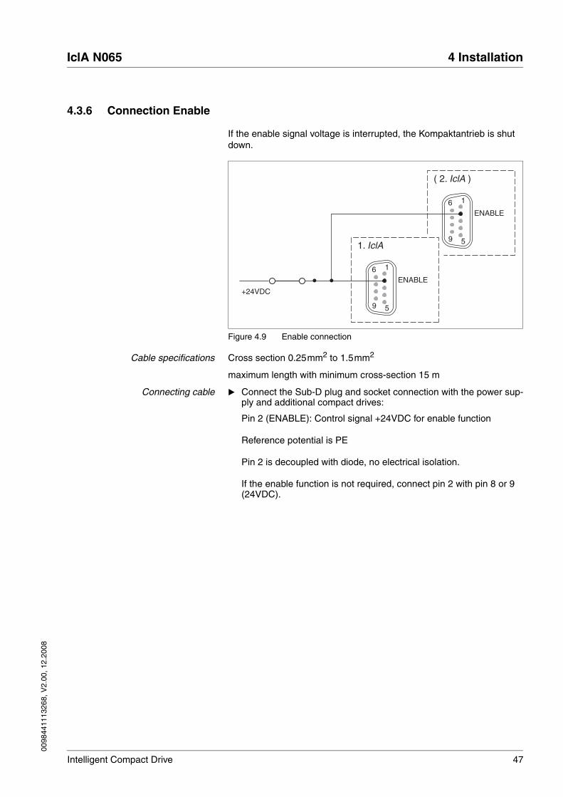
4.3.6 Connection Enable
If the enable signal voltage is interrupted, the Kompaktantrieb is shut down.
Figure 4.9 Enable connection
Cable specifications Cross section 0.25mm2 to 1.5mm2
maximum length with minimum cross-section 15 m
Connecting cable � Connect the Sub-D plug and socket connection with the power sup-ply and additional compact drives:
Pin 2 (ENABLE): Control signal +24VDC for enable function
Reference potential is PE
Pin 2 is decoupled with diode, no electrical isolation.
If the enable function is not required, connect pin 2 with pin 8 or 9 (24VDC).
1
5
6
9
( 2. IclA )
ENABLE
1
5
6
9
1. IclA
ENABLE
+24VDC

48 Intelligent Compact Drive
4 Installation IclA N065
0098
4411
1326
8, V
2.00
, 12.
2008
4.3.7 Fieldbus connection
circular plug-in connector,assignment of input plugs
The compact drive is connected to the CAN fieldbus with the circular plug-in connector, 5-pin model.
Figure 4.10 CAN fieldbus connection (input plug)
Circular plug-in connector,assignment of output socket
The compact drive has a second circular plug-in connector, 5-pin model, for networking the CAN fieldbus. Additional network devices can be con-nected here.
Figure 4.11 CAN fieldbus connection (output socket)
Accessories for networking Cable connectors, terminal blocks and terminating resistors for the com-pact drive can be found in the accessories list in chapter 8 "Accessories and spare parts".
Connecting cable � Connect the fieldbus cable to the circular plug-in connector (input connector) of the compact drive. If no other devices are to be con-nected, the second circular plug-in connector (output socket) must have a terminating resistor.
1 CAN_SHLD
5 CAN_L
2 -
3 CAN_0V
4 CAN_H
1 1
3 3
4 4
5 5
5
2
13
4
Pin Signal Description
1 CAN_SHLD Shielding, PE connection
2 - not assigned
3 CAN_0V CAN ground
4 CAN_H Data wire, dominant high
5 CAN_L Data wire, dominant low
1 CAN_SHLD
5 CAN_L
2 -
3 CAN_0V
4 CAN_H
1 1
3 3
4 4
5 5
5
2
4
1 3
Pin Signal Description
1 CAN_SHLD Shielding, PE connection
2 - not assigned
3 CAN_0V CAN ground
4 CAN_H Data wire, dominant high
5 CAN_L Data wire, dominant low

0098
4411
1326
8, V
2.00
, 12.
2008
IclA N065 4 Installation
Intelligent Compact Drive 49
� Otherwise a t-piece or a plug with two cable outputs can be con-nected to the input connector to connect adjacent fieldbus devices. The output socket must not be wired with a terminating resistor in this case.
Install the t-piece on the compact drive without a drop line.
The two open ends in the CAN fieldbus must be connected with a 120Ω resistor.
The maximum cable length of a CAN network depends on the baud rate at which the network is to be operated. The higher the baud rate, the shorter the bus cable needs to be.
The following example shows the networking of four compact drives with a PLC.
Figure 4.12 Networking of four compact drives with a PLC
Baud rate [Kbd]
Cable length [m] Baud rate [Kbd]
Cable length [m]
1000 25 100 600
800 50 50 1000
500 100 20 2500
250 250 10 5000
SocketPlug
Terminating resistor(see accessories)
PLC(with terminating resistor)

50 Intelligent Compact Drive
4 Installation IclA N065
0098
4411
1326
8, V
2.00
, 12.
2008
4.3.8 Connection Braking Resistor Controller
A braking resistor controller can be connected to the signal CHOPPER. A braking resistor controller is required if the supply voltage gets too high due to reverse feeding.
Figure 4.13 Connection Braking Resistor Controller
Cable specifications • Cross section 0.75 ... 1.5 mm2
Connecting cable � Connect the Sub-D connector to the input of the braking resistor controller.
IMPORTANT: The signal CHOPPER may only be connected directly to the input of the braking resistor controller.
Several compact drives can not be connected directly to a braking re-sistor controller.
If you have any questions please contact your local dealer. Your dealer will be happy to give you the name of a customer service outlet in your area.
0VDC
VDC
UBC60
IclA
CHOPPER

0098
4411
1326
8, V
2.00
, 12.
2008
IclA N065 4 Installation
Intelligent Compact Drive 51
4.3.9 Checks
System checks and test � Carry out these checks:
Are all cables and connectors safely installed and connected?
Are any live cable ends exposed?
Are the control lines connected correctly?
For this test and the first stages of commissioning the motor should be run decoupled from the system. This prevents damage to motor and system if the motor starts unexpectedly or by incorrect referencing marks.
� Switch on the 24VDC power supply. The drive runs a self-test and switches to manual operation mode.
Manual movement test If the drive is referenced and the signal connections are wired for manual mode, the function of the drive can be tested in manual mode. The motor cannot move without valid reference values. The drive can only be ref-erenced over the fieldbus.
� Switch the manual movement signals for clockwise and anti-clock-wise rotation to low level.
If MAN_P is wired, the shaft rotates clockwise when viewed towards the face of the driven shaft. The supply voltage and manual move-ment signals are then correctly wired.
Testing fieldbus wiring � With the power off measure the resistance between CAN_L and CAN_H.
If the measured value with both terminating resistors is 60Ohm, the network is correctly wired and connected.
@ WARNINGUnexpected movement
When the drive is operated for the first time there is a high risk of un-expected movements because of possible wiring errors or unsuitable parameters.
• If possible, run the first test movement without coupled loads.
• Make sure that a functioning button for EMERGENCY STOP is within reach.
• Also anticipate a movement in the incorrect direction or oscillation of the drive.
• Make sure that the system is free and ready for the movement before starting the function.
Failure to follow these instructions can result in death, serious injury or equipment damage.

52 Intelligent Compact Drive
4 Installation IclA N065
0098
4411
1326
8, V
2.00
, 12.
2008

0098
4411
1326
8, V
2.00
, 12.
2008
IclA N065 5 Commissioning
Intelligent Compact Drive 53
5 Commissioning
5.1 General safety instructions
@ CAUTIONHot Surfaces
Depending on the operation the surface may heat up to more than 100°C (212°F).
• Prevent contact with the hot surfaces.
• Do not install flammable or heat-sensitive components in the immediate vicinity.
• Follow the actions described for heat dissipation.
• Check the temperature during the test run.
Failure to follow these instructions can result in injury or equip-ment damage.
@ WARNINGUnexpected movement
When the drive is operated for the first time there is a high risk of un-expected movements because of possible wiring errors or unsuitable parameters.
• If possible, run the first test movement without coupled loads.
• Make sure that a functioning button for EMERGENCY STOP is within reach.
• Also anticipate a movement in the incorrect direction or oscillation of the drive.
• Make sure that the system is free and ready for the movement before starting the function.
Failure to follow these instructions can result in death, serious injury or equipment damage.
54 Intelligent Compact Drive
5 Commissioning IclA N065
0098
4411
1326
8, V
2.00
, 12.
2008
@ WARNINGUnexpected behaviour
The behaviour of the drive system is governed by numerous stored data or settings. Unsuitable settings or data may trigger unexpected movements or reactions to signals and disable monitoring functions.
• Do not operate a drive system with unknown settings or data.
• Check the stored data or settings.
• When commissioning carefully run tests for all operating statuses and fault cases.
• Check the functions after replacing the product and also after making changes to the settings or data.
• Only start the system if there are no persons or materials in the danger zone and the system can be operated safely.
Failure to follow these instructions can result in death, serious injury or equipment damage.
@ WARNINGUnbraked motor
In the case of power failure and faults which cause the power amplifier to be switched off, the motor is no longer controlled by the brake and increases its speed even more until it comes to a mechanical stop.
• Check the mechanical situation.
• If necessary, use a cushioned mechanical stop or a suitable brake.
Failure to follow these instructions can result in death, serious injury or equipment damage.
@ WARNINGRotating parts
Rotating parts may cause injuries and may catch clothing or hair. Loose parts or parts that are unbalanced may be thrown clear.
• After mounting check all rotating parts (parallel keys, coupling, ..).
• Use a cover as protection against rotating parts.
Failure to follow these instructions can result in death, serious injury or equipment damage.

0098
4411
1326
8, V
2.00
, 12.
2008
IclA N065 5 Commissioning
Intelligent Compact Drive 55
When commissioning you can use the commissioning software to switch between "Standard Interface" and "Sensor Interface" (parameter group "Drive data", parameter "Interface option type").
5.2 Commissioning procedure
The steps for commissioning and parameterising the operating modes and functions over the fieldbus are described in the fieldbus manual for the compact drive.
The following commissioning steps are also required if you are using a configured unit under changed operating conditions.
@ WARNINGFalling parts
The motor may move as a result of the reaction torque, tip and fall.
• Fasten the motor securely to prevent it from breaking loose dur-ing strong acceleration.
Failure to follow these instructions can result in death, serious injury or equipment damage.

56 Intelligent Compact Drive
5 Commissioning IclA N065
0098
4411
1326
8, V
2.00
, 12.
2008
5.3 Commissioning software ICCT
Features The commissioning software simplifies commissioning, parameterisa-tion, simulation and diagnostics.
It provides extensive options such as:
• Graphic interface for parameter setting and status display
• Extensive diagnostic tools for optimisation and maintenance
• Long-term recording as an aid to assessing operating behaviour
• Testing input and output signals
• Tracking signal sequences on the monitor
• Archiving all device settings and recordings with export functions for data processing
Requirements • PC or laptop with Windows 2000 or later
• Converter for fieldbus connection to PC
• Product manual: Commissioning software ICCT
Converter You require a converter to connect the product to the PC. The following converters are recommended:
• "USB-to-CAN compact", www.ixxat.com
• "PCAN-USB", www.peak-system.com
Source commissioning software The latest version of the commissioning software is available for down-load from the internet:
http://www.schneider-electric-motion.com
5.3.1 Firmware update over fieldbus
Finding the firmware version The firmware number and the firmware version of your drive can be found with the commissioning software by opening the device informa-tion window.
@ CAUTIONDamage to the product from failure of the supply voltage
If the supply voltage fails during an update, the product will be dam-aged and must be sent in for repair.
• Never switch off supply voltage during the update.
• Always carry out the update with a reliable supply voltage.
Failure to follow these instructions can result in injury or equip-ment damage.

0098
4411
1326
8, V
2.00
, 12.
2008
IclA N065 5 Commissioning
Intelligent Compact Drive 57
5.4 Difference between the controller objects of D065 and N065
The controller objects of the D065 (Object 2010hControl Parameter Set) are not compatible with the controller objects of N065. Thus 1 to 1 use is not possible.
The behaviour of the N065 when using the factory settings shows virtu-ally identical behaviour to the D065 when using the factory settings. Ret-rospectively changed controller objects have to be reset for the N065.
The following objects have been replaced by new objects.
Some of the new objects have a different scale.
The meaning of the individual objects is described in the relevant field-bus manual.
D065 Object (Indexh:Subindexh) N065 Object (Indexh:Subindexh)
KP_Pos (2010:01) no equivalent
KP_Rpm (2010:02) Gain (60F9:01)
KP_Cmd (2010:03) KP_Cmd (60F9:09)
RI_Lag (2010:04) IntegrationTimeConstant (60F9:02S)
PositionWindow (2010:05) PositionWindow (6067:00)
RpmWindow (2010:06) VelocityWindow (606D:00)
RpmDeviationEvents (2010:07) VelocityWindowTime (606E:00)
RpmStartTimeout (2010:08) StartUpTimeout (60F9:03)
RpmStop (2010:09) no equivalent
LP1_TimeConst (2010:0A) LP1_TimeConstant (60F9:08)
HoldingTorqueTime (2010:0B) HoldingTorqueTime (60FB:01)
MaxSteadyCurrent (2010:0C) no equivalent
StartingCurrentFactor (2010:0D) AccelerationCurrentFactor (60F9:05)
DeviationDelay (2010:0E) ConstantDriveDelay (60F9:04)
CurrentDeviationEvents (2010:0F) MaxCurrentEvents (60F9:06)
Current window (2010:10) no equivalent
BlockDeceleration (2010:11) BlockDeceleration (60F9:07)

58 Intelligent Compact Drive
5 Commissioning IclA N065
0098
4411
1326
8, V
2.00
, 12.
2008

0098
4411
1326
8, V
2.00
, 12.
2008
IclA N065 6 Operation
Intelligent Compact Drive 59
6 Operation
6.1 Operating modes
The compact drive operates with seven operating modes:
After switching on the supply voltage, the compact drive automatically switches to manual operation. The drive can be switched to fieldbus con-troller via the fieldbus.
Figure 6.1 Operating modes of the Kompaktantriebs
Manual operation via signals In manual operation the Kompaktantrieb moves at an adjustable speed within the referenced working range. The direction of movement and the jog operating mode or continuous operation are preset by two signal in-puts.
Manual operation via fieldbus In manual operation via fieldbus the Kompaktantrieb can also be moved clockwise or anticlockwise within the reference range. The direction of motion and the speed are specified over the fieldbus.
Operating modes with fieldbus without fieldbus
Manual operationvia signal inputs MAN_N and MAN_P
x x
Manual operationvia CAN bus (simulated manual mode)
x –
Homing x –
Positioning mode x –
Speed control mode x –
Configuration mode x –
Manufacturer-specific positioning mode (manufacturer-specific travel profile)
x –
24V On Manual operation
Manual operation via signal inputs
Manual operation via CAN busReferencing
without field bus:
with field bus:
Field bus command
Network
Positioning modeVelocity modeConfiguration modeManufacturer specific positioning mode

60 Intelligent Compact Drive
6 Operation IclA N065
0098
4411
1326
8, V
2.00
, 12.
2008
Homing The compact drive must be referenced for manual or positioning mode. The homing specifies three limit switch points for every direction of mo-tion. The drive monitors them continuously for overshoot. A homing is also retained after switching the compact drive off and on if they were not rotated when the power was off.
Positioning mode In positioning mode the referenced drive can be moved from a point A to a point B. A trapeze profile is specified; application-specific trapeze pro-files with values for final speed and acceleration and deceleration ramps can be saved in nine additional parameter sets.
Speed control mode In speed control mode movement commands are processed via the fieldbus. In this operating mode the drive requires homing if the software limit switches are used. The function of the software limit switches can be disabled by setting parameters of all software limit switches to the minimum or maximum range limits. The drive can then be moved in speed control mode without homing.
The reference value of a movement command is the set speed of the drive movement. The acceleration and braking ramp is parameterised and can be adjusted for the specific application.
6.2 Functions
Communication configuration Communication parameters of the compact drive can be set for data ex-change over fieldbus.
In the CANopen network the parameters baud rate and node number can be modified via the LSS service (layer setting services).
Configuration mode Parameter values of the compact drive can only be set via the fieldbus. The configuration mode offers the option of adjusting the compact drive for the operating conditions.
Figure 6.2 Communication configuration and configuration mode
Field bus control:field bus
command
field buscommand
field buscommand
Network
Communicationsconfiguration:
Parameter settingvia field bus
Configuration mode:
IclA-parameter settingsProgramming integrated in the application
Manual operation via signal inputs
Manual operation via CAN bus
Referencing
Positioning modeVelocity modeConfiguration mode
Manufacturer specific positioning mode

0098
4411
1326
8, V
2.00
, 12.
2008
IclA N065 6 Operation
Intelligent Compact Drive 61
6.3 Protection and monitoring functions
Figure 6.3 Enable function and monitoring function
6.3.1 Enable function
The enable function is triggered via a fieldbus command or alternatively by interrupting the enable control signal. The current travel command is cancelled in different ways.
In the case of the fieldbus command an error flag is set and the motor is brought to a standstill with the Quick Stop ramp.
The interruption of the enable control signal triggers a time-delayed de-activation of the power electronics. The drive is braked at maximum power. After elapse of the delay time the power electronics are disabled. The error flag is set.
Moving loads are not permitted when using the enable function, e.g with Z-axes, because the drive is actively braked for just one second after enabling the enable control signal. A continuing application with a moving load may result in unwanted drive movements.
The compact drive remains at a standstill until the external control resets the enable status.
Manual operation via fieldbus
Referencingto signal input
Positioning mode
Manual-/field bus control:
Velocity mode
Manual operaton via signal inputs
Referencingvia fieldbus
Monitoring:
� Current limitationOverloadVoltagesTemperatureStart-up errorSpeed-deviationBlock movementCommutation-Hall sensor error
�
�
�
�
�
�
�
�
�
�
ExternalaccelerationElectroniclog book
Watchdog
�
�
�
�
Saving of data
Start-up diagnosis
Enable- function
24V Off
24V On

62 Intelligent Compact Drive
6 Operation IclA N065
0098
4411
1326
8, V
2.00
, 12.
2008
6.3.2 Monitoring functions of the motor controller
Various operating functions provide protection against damage and mal-functions. This includes:
• Self-test at Power On (start diagnosis of the integrated electronics)
• Data backup when the supply voltage is switched off
• Current limiting
• Overload
• Voltages
• Temperature
• Starting error
• Deviation in rpm
• Block movement
• Commutation/Hall sensor error
• Outside acceleration
• Electronic log-book
• Watchdog (program process monitoring)
6.3.2.1 Self-test at Power On
After Power On the application program calls the initialisation routine of the motor management system, where a self-test of the following func-tions is run.
• Timer and oscillator
• Configuration memory (consistency of the non-volatile data in the EEPROM)
• Combination of the Hall sensors
• Motor current
• DC bus and auxiliary voltage
• Temperature of the power electronics
• Wire break (functional readiness of the Enable hardware)
• Check historical watchdog
• Test for dereferencing
With the error a corresponding error flag is set in the drive status regis-ter.
A distinction can be made between reversible and non-reversible (fatal) errors, which must be treated differently.
The fatal errors include EEPROM errors (loss of data and movement log-book), Enable self-test errors, watchdog errors and timer and oscil-lator errors. In these cases the system is held in an endless loop to pre-vent activation of an invalid operating status. After Power On the drive simply sends a BootUp message and the assigned error message. Oth-erwise the system shows no outside response. Only a manufacturer-specific host system can detect this status. The user should send drive systems with the error type described above in for closer examination.

0098
4411
1326
8, V
2.00
, 12.
2008
IclA N065 6 Operation
Intelligent Compact Drive 63
In the case of the reversible self-test errors the system branches into the basic loop. The motor controller is not enabled; an error message is sent over the bus interface.
If the supply voltage fails the run-time data are written to the configura-tion memory (Power Fail Save). The primary data are the position of the drive in the position memory (position counter) and the current rotor po-sition. The voltage monitor detects the Power Down, stops the motor and initialises the Power Fail Save sequence. The data are written to the configuration memory as soon as the drive is at a standstill in the event of a Power Down:
• Position counter (current position in the position memory)
• Hall combination (to detect mechanical displacement)
• Status register (controller status at Power Down)
• Log-book (operating hours, etc.)
A validity bit is set in the configuration memory at Power Down to test the validity of the run-time data. The validity bit is read from the configuration memory at the next Power On and reset there immediately, i.e. the run-time data in the configuration memory are flagged as invalid.
If the validity bit is not set at Power On, the last backup of the run-time data did not work. The run-time data in the configuration memory do not refer to the last Power Fail Save; this has the following consequences:
• the position counter is invalid: the drive must be referenced again,
• the Hall combination is invalid: the drive must be referenced again,
• the status registers are invalid: insignificant, because it is historical
• the log-book is invalid: the data must be reconstructed.
6.3.2.2 Current limiting
If the motor phase current reaches the maximum value that can be set by the user, it is limited by the electronics. The warning flag "current lim-iting" is set in the status register.
6.3.2.3 Overload
The overload is calculated by the I2t method. If the calculated motor phase current exceeds the value of the permissible continuous current for a specified time, the drive is stopped and the error flag "overload" is set. The time until enabling the error depends on the height of the meas-ured current.

64 Intelligent Compact Drive
6 Operation IclA N065
0098
4411
1326
8, V
2.00
, 12.
2008
6.3.2.4 Voltages
The three parameters power supply, DC bus and auxiliary voltage are continuously measured, filtered and compared with limit values. Various actions may follow depending on the type of voltage.
The measured values can be read out over the field bus interface
6.3.2.5 Temperature
The temperature of the motor electronics are continuously measured and evaluated. If the warning threshold is exceeded the warning flag is set in the status register. If the shut-down threshold is exceeded the er-ror flag is set, the motor is braked at the Quick-Stop ramp and the error message assigned to the overtemperature error is output. When the mo-tor is at a standstill the power electronics are switched off.
If the temperature falls below the configured reset threshold, the motor controller can be enabled via the application program.
The temperature of the power electronics can be queried via the CAN bus.
The values for overtemperature and reset threshold are saved in the configuration memory of the drive and can be queried over the bus in-terface (electronic data sheet).
6.3.2.6 Starting error
If the motor does not start within a configurable time, the power electron-ics are switched off and an error flag is set. The system waits for a new movement command. The system continues to remain in the "ready" status and can process new movement commands.
6.3.2.7 Speed deviation
If the control deviation of the speed of rotation exceeds a defined limit value after completion of the acceleration phase in the range of constant setpoint speed, the speed deviation error flag is set. The sped deviation
Power supply DC link Auxiliary voltage
Overvoltage (>20%) Warning flags are set in status word and status register,
no error message (EMCY)
Warning flags are set in status word and status register,
no error message (EMCY)
Warning flags are set in status word and status register,
no error message (EMCY)
Overvoltage (illegal range e.g. by mov-ing load)
- Error flag, braking ramp is delayed,
power electronics switch off, out-put of assignederror message (EMCY)
-
Undervoltage (<20%)
Warning flags are set in status word and status register,
no error message (EMCY)
Warning flags are set in status word and status register,
no error message (EMCY)
Warning flags are set in status word and status register,
no error message (EMCY)
Undervoltage(Fail Safe)
Error flag, motor at maximum braking, data backup,
output of assignederror message (EMCY)
Error flag, motor at maximum braking, data backup,
output of assignederror message (EMCY)
-

0098
4411
1326
8, V
2.00
, 12.
2008
IclA N065 6 Operation
Intelligent Compact Drive 65
does not indicate an error in all cases; incorrect selections, such as ex-cessively low current setpoints, could also be the cause.
6.3.2.8 Block movement
If the speed of rotation falls by a configurable value within a permanently defined period and the current limiting is active at the same time, a block movement is detected. It is displayed by a corresponding entry in the er-ror flag.
6.3.2.9 Commutation/Hall sensor errors
The motor electronics check the measuring signals for determination of the rotor angle (Hall signals) for plausibility. If an error in a signal is de-tected, it is shown by an error flag.
6.3.2.10 Outside acceleration
Various functions protect the drive from damage resulting from outside acceleration.
Two different operating states must be distinguished.
• During a positioning process a moving load is applied to the output during braking. Because the drive is actively braking in this phase, a component of the braking energy is fed to the DC bus circuit, which increases the voltage.
The drive responds to rising voltage values in three stages: genera-tion of a warning flag, reduction of the braking ramp and finally by switching off the power electronics, which is acknowledged by the error message "overvoltage" (see section 6.3.2.4 "Voltages").
• The drive is accelerated out of standstill by an outside force to dis-place is manually. If the drive is accelerated past the maximum per-mitted speed of rotation specified in the electronic data sheet, it may be damaged by the high induced voltage.
– If the drive is connected to a power supply and there is no Ena-ble signal, the drive is protected against overvoltage by a short-circuit braking. The short-circuit braking is tripped if the permis-sible maximum speed is exceeded by 25%.
If the Enable signal is active and the power electronics are disa-bled, the protective function is also disabled. The drive will then be damaged if the maximum speed is exceeded.
– If the drive is not connected to a power supply, there is no pro-tection against overload by an auxiliary drive.
6.3.2.11 Electronic log-book
The following data are recorded in the electronic log-book:
• Uptime of the drive
• Active time of the drive
• Number of positionings
• Number of reference losses
• Number of log-book losses

66 Intelligent Compact Drive
6 Operation IclA N065
0098
4411
1326
8, V
2.00
, 12.
2008
The log-book is continuously updated during the operating time and writ-ten to the configuration memory on Power Down.
Because a loss of run-time data and also the log-book cannot be com-pletely prevented on Power Down, a second log-book is also main-tained. It is periodically written to the configuration memory during operation. The log-book can be reconstructed from the second log-book after a loss of run-time data. The data error during the time counters is less than a backup period in this case.
6.3.2.12 Watchdog
The Watchdog timer is a monitoring mechanism for responding to hard-ware faults and "software hang-ups". The Watchdog timer is enabled at Power On and must be serviced cyclically by the software (Watchdog Servicing).
If the Watchdog Servicing fails, the microcontroller performs a Watch-dog reset. The systems runs the Power On self-test and the initialisation phase. The motor controller is not enabled. An error message is set via the bus interface.
This status can only be reset by a hardware reset (switching off the sup-ply voltage). This is a non-reversible error. Drives with this error type should be sent in for closer examination.

0098
4411
1326
8, V
2.00
, 12.
2008
IclA N065 7 Diagnostics and troubleshooting
Intelligent Compact Drive 67
7 Diagnostics and troubleshooting
7.1 Fieldbus communication error diagnosis
Field-mode must be functioning to be able to evaluate operational and error messages. The Kompaktantrieb can only exchange messages via the fieldbus.
Connections to field-bus mode If the drive cannot be addressed over the field bus, first check the con-nections. Kompaktantriebcompact drive contains the technical data on the device and information on network and device installation. Check the following:
• 24V power supply
• Power connections to the device
• Fieldbus cable and wiring
• Network connection to the device
Function test on the fieldbus If the Kompaktantrieb is connected up correctly then test field bus oper-ation. This requires installation of a CAN monitor that displays CAN messages. Acknowledgement of the drive is captured by a boot-up mes-sage:
� Switch the drive power supply off and on again.
� Observe the network messages shortly after switching on the device. The Kompaktantrieb sends a 1-byte long boot-up message after bus initialisation: 1792 (700h)+node ID.
� With the node address factory setting to "127" (7Fh), the boot-up message "2047" (77Fh) is sent over the bus. The drive can then be put into operation via LSS and NMT services.
If no boot-up message is received on the network after switching on the drive, first check whether the baud rate of the CAN monitor matches the set baud rate in the network.
If network operation cannot be started, the network function of the device must be checked by your local representative. Contact your local representative.
Baud rate and address If a connection to a device cannot be made, check the baud rate and node address.
• The baud rate of all network devices must be set to the same value
• The node address of every device must be between 1 and 127 and must be different for every device.
The default baud rate is 20 kbps. The default address is 127.
The baud rate and node address for the Kompaktantrieb can be set with LSS services, see CANopen manual, "LSS services in the positioning drive".

68 Intelligent Compact Drive
7 Diagnostics and troubleshooting IclA N065
0098
4411
1326
8, V
2.00
, 12.
2008
7.2 Error diagnosis over fieldbus
7.2.1 Message objects
Several objects provide information on the operation and error status of the Kompaktantriebs:
• Object Statusword (6041h)operating statuses which are reported over the status word are described in the CANopen manual in the chapter "Operating sta-tuses and operating modes“.
• Object EMCY(80h+ node-Id)error message of a user with error status and fault code; see CAN-open manual, chapter "Emergency service“.
• Object Manufacturer status register (1002h)operation and error status of the device components, this is where the manufacturer-specific message on the Kompaktantrieb are stored. The object remains set after an error status until a new posi-tioning order is executed or the original source of the malfunction is removed. Detailed information on this can be obtained from the fol-lowing 7.2.2 "Messages on the device status"chapter.
• Object Error register (1001h)shows the error status of a device in bit-coded form. The exact cause of error must be determined with the error code table. Bit 0 is set as soon as an error occurs.
• Object Error code(603Fh)The error code is analysed by the object error code(603Fh), an object of the device profile DSP 402 and is issued as a 4-digit hexa-decimal number. The error code shows the cause of the last inter-ruption of movement. The meaning of the error code can also be found in the CANopen manual in the section on error diagnosis and troubleshooting.
• Object Predefined error field (1003h) error memory contains the last five occurring errors as an error code in chronological order.
Bit Message Description
0 generic error An error has occurred
1 current The parameterised range limits of the maxi-mum motor current or the I2t monitoring were exceeded
2 voltage Detection of overvoltage or undervoltage for the internal auxiliary voltage (12V), supply voltage or DC bus voltage
3 temperature The maximum permissible limit temperature was exceeded (internal measurement)
4 communication error Error in the network communication
5 device profile-specific Error during execution of the command according to device profile (e.g. block move-ment)
6 reserved Reserved
7 manufacturer-specific Manufacturer-specific error message (e.g. external torque)
0098
4411
1326
8, V
2.00
, 12.
2008
IclA N065 7 Diagnostics and troubleshooting
Intelligent Compact Drive 69
• Devices use the special SDO ABORT error message to report the failed message exchange via SDO (abort)
Validates transmitted LSS services "Transmitting acknowledgement in-formation" or an error code. The meaning of the feedback message to each LSS service is described in the CANopen manual, chapter "Ba-sics“.
7.2.2 Messages on the device status
The 32 bit object "Manufacturer status register" (1002h) of the engine operating programme is the central register of engine interface.
Bits 24 - 31 inform about the operating status of the engine control.
Bits 0 - 22 inform about the error status of the various monitoring func-tions.
Errors occurring can be analysed in detail via bits 0 - 23
Operation and error messages indicate the drive bitcoded.
For error analysis and handling purposes one differentiates between re-versible and fatal errors as well as note messages.
Warning (Warn) A Warning (object 1002h/Bit30) indicates that the drive is in a critical but not yet operation-endangering condition (value = 1). The exact origin of the problem is stored in bits 23 to 0 of the status register (object 1002h).
The warning bit and the bit(s) which indicate the origin of the problem re-main until a new travel command is discharged, that is possible origins of problems can also be called up after completing a travel command.
Reversible error (Rev) If the drive detects a reversible error, it sends an EMCY message over the fieldbus and stops the current movement operation. After the error has been corrected, the error message must be acknowledge via bit 7, Reset fault in the control word Controlword (6040h).
In the event of a reversible error bit 7 in the object Statusword (6041h) and bit 30 in the object manufacturer status register (1002h) are set.
Fatal error (fatal) A fatal error occurs when the internal device test detects hardware or software errors. The motor controller is blocked; the block can only be reset by switching the drive off and on again.
The drive sends an EMCY message.
Message The entry "Info" in the column ""Type of message"" indicates that a note was issued without interruption of the currently running movement mode.
The following table shows the bit values of the object Manufacturer status register (1002h).

70 Intelligent Compact Drive
7 Diagnostics and troubleshooting IclA N065
0098
4411
1326
8, V
2.00
, 12.
2008
Bit Designa-tion
Possible cause for the message
Type of message
Remedy EMCY message
0 Configura-tion error drive parameter
Reading/writing error or plausibility error when copying drive parame-ters (control parameter, communications param-eter, application parame-ter or identification parameter) from the con-figuration memory (EEP-ROM ).
Warning Check user settings for plausibility and correct or go back to the factory setting. Bit 30 = 1!
No
Fatal There is an EEPROM memory error; the drive must be replaced and sent back to the manufac-turer Bit 31 = 1!
Yes / EMCY code 6310h
1 Configura-tion error in drive data
Reading/writing error or plausibility error when copying drive data from the configuration mem-ory (EEPROM).
Fatal There is an EEPROM error in the memory area of the drive and motor data. The drive must be replaced and sent back to the manufacturer.Bit 31 = 1!
Yes / EMCY code 6310h
2 Self test error in Enable input circuit
Error during testing of the Enable hardware during the self test phase (occurs with every switching on of the power supply)
Fatal Possible defect in the Enable hardware. The drive must be replaced and sent back to the manufacturer Bit 31 = 1!CAUTION: If the drive is turned during the initial-isation and self test phase then this will result in an Enable self-test error!
Yes / EMCY code 5000h
3 Auxiliary voltage undervolt-age (12VDC)
Going below the toler-ance limit (10VDC) or going below the switch off limit (8.5VDC).
Warn/Rev 1) Going below the tolerance limit 10VDC:Bit3 in object 1002h is set. The full drive function continues to be accessible. Bit 30 = 1!2) Going below the switch off limit 8.5VDC: Bit3 in object 1002h is set. The drive stores all run-time data and is put into initialisation status for a self-reset. Bit 31 = 1! Measure: In both cases check stability of the central power supply! If the error occurs again or is not removed after initialisation then the drive must be replaced and sent back to the manufac-turer.
1) No2) Yes / 5110h
4 DC bus overvoltage
Exceeding the tolerance limit (24VDC +20%) or the maximum switch off limit (about 39VDC)
Warn/Rev 1. Exceeding the tolerance limit of 24VDC +20%:Bit4 in object 1002h is set. The full drive function continues to be accessible. Bit 30 = 1! Exceeding the switch off limit of 39VDC:Bit4 in object 1002h is set. The drive stores all run-time data and is put into initialisation status for a self-reset. Bit 31 = 1! Measure: In both cases check stability of the central power supply! If the error occurs again or is not removed after initialisation then the drive must be replaced and sent back to the manufac-turer.
1) No2) Yes / 3210h

0098
4411
1326
8, V
2.00
, 12.
2008
IclA N065 7 Diagnostics and troubleshooting
Intelligent Compact Drive 71
5 DC bus undervolt-age
Going below the toler-ance limit (24VDC -20%) or the switch off limit (15VDC) of the DC bus voltage
Warn/Rev 1) Going below the tolerance limit of 24VDC -20%)Bit5 in object 1002h is set. The full drive function continues to be accessible.Bit 30 = 1!2) Going below the switch off threshold of 15VDC:Bit5 in object 1002h is set. The drive stores all run-time data and is put into initialisation status for a self-reset.Bit 31 = 1! Measure: In both cases check stability of the central power supply! If the error occurs again or is not removed after initialisation then the drive must be replaced and sent back to the manufac-turer.
1) No2) Yes / 3220h
6 Supply volt-age over-voltage
Exceeding the tolerance limit of the supply voltage 24VDC +20%
Warning Exceeding the tolerance limit of 24VDC +20%:Bit6 in object 1002h is set. The full drive function continues to be accessible. Bit 30 = 1!
No
7 Supply volt-age under-voltage
Going below the toler-ance limit (24VDC -20%) or the switch off limit (12VDC) of the supply voltage
Warn/Rev 1 Going below the tolerance limit of 24VDC -20%)Bit7 in object 1002h is set. The full drive function continues to be accessible.Bit 30 = 1!2. Going below the switch off threshold of 12VDC:Bit7 in object 1002h is set. The drive stores all run-time data and is put into initialisation status for a self-reset.Bit 31 = 1! Measure: In both cases check stability of the central power supply! If the error occurs again or is not removed after initialisation then the drive must be replaced and sent back to the manufac-turer.
1) No2) Yes / 3120h
8 Oscillator watchdog
An excessively high vari-ation of the oscillator fre-quency or the oscillator does not reach the spec-ified frequency.
Fatal The drive must be replaced and sent back to the manufacturer.Bit 31 = 1!
Yes / 0x6000
9 Watchdog timer reset
Reset of the microcon-troller by the watchdog timer
Fatal The drive must be replaced and sent back to the manufacturer.Bit 31 = 1!
Yes / 0x6000
10 Class B hardware trap
Error message from an internal software moni-toring function
Fatal The drive must be replaced and sent back to the manufacturer.Bit 31 = 1!
Yes / 0x6000
11 Class B hardware trap
Error message from an internal hardware moni-toring function
Fatal The drive must be replaced and sent back to the manufacturer.Bit 31 = 1!
Yes / 0x6000
12 not assigned
13 EEPROM error (stor-ing run-time data)
Error in reading the run-time data previously stored in the EEPROM (logbook)
Fatal The drive must be replaced and sent back to the manufacturer.Bit 31 = 1!
Yes / 0x5530
Bit Designa-tion
Possible cause for the message
Type of message
Remedy EMCY message

72 Intelligent Compact Drive
7 Diagnostics and troubleshooting IclA N065
0098
4411
1326
8, V
2.00
, 12.
2008
14 ROM error (pro-gramme memory)
Not implemented on the IclA N065
15 RAM error (data mem-ory)
Not implemented on the IclA N065
16 An unex-pected Hall sensor combination
An undefinable Hall sen-sor combination occurs or a sequence occurs during the commutation sequence a number of times
Fatal The drive must be replaced and sent back to the manufacturer.Bit 31 = 1!
Yes / 0x7122
17 Start up error on the motor
No Hall sensor signals after the start up phase, an excessively high start up torque, drive blocked
Warning Reduce load, increase operating current or peak current, increase value of the acceleration rampBit 30 = 1!
Yes / 0x71AA
18 Deviation in rpm
An excessively high start up torque
Warning Reduce load, increase operating current or peak current, increase value of the acceleration ramp, choose a low speed of rotationBit 30 = 1!
Yes / 0x71BB
19 Current lim-iting
The motor current is lim-ited by the parameter-ised maximum current (lowest maximum value from the motor or elec-tronic parameters).
Warning Reduce load Bit 30 = 1!
Yes / 0x2222
20 Block move-ment
Movement onto an obstacle leads to a drop in speed of rotation or stopping and to an over-current.
Rev Remove the cause of the blockage (obstacle, dead stop, ...). In field bus operation:Perform FaultReset (Bit7/object 6040h).In manual mode:Remove power supply, remove the cause of the blockage, switch on again. Bit 31 = 1!
Yes / 0x7121
21 Overload (I2t)
The measured motor current is above the per-missible continuous engine current (calcula-tion with the aid of the I2t method, thermal motor monitoring)
Rev Reduce load or increase operating current. The drive executes a rapid stop. Bit 31 = 1!
Yes / 0x2221
22 Exces-sively high tempera-ture of the power elec-tronics
Exceeding the parame-terised temperature limit values
Warn/Rev 1. Exceeding the temperature warning threshold of 80°C: Bit22 in object 1002h is set. The full drive function continues to be accessible.Bit 30 = 1!2. Exceeding the temperature switch off thresh-old of 90°C: Bit22 in object 1002h is set. The drive is stopped.Bit 31 = 1!Measure: The drive can be moved again when it has cooled down to below the temperature warning threshold.
1) No2) Yes / 0x4310
Bit Designa-tion
Possible cause for the message
Type of message
Remedy EMCY message

0098
4411
1326
8, V
2.00
, 12.
2008
IclA N065 7 Diagnostics and troubleshooting
Intelligent Compact Drive 73
23 External torque
The drive is pulled out of its rest condition by an external torque. Activa-tion of the message takes place depending on the presettings in object “Position win-dow”, 6067h.
Warn/Rev Checking of the mechanical system.Bit 30 = 1!
Yes / 0xFF29
24 Drive refer-enced
1: Drive is referenced, which means that the commutation pattern and the co-recorded position concur.
---- No measure necessary.
0: The drive is not refer-enced! Cause: The drive was moved while not under power (effect of an external force). Bit 31= Bit 30, both are 0!
The drive must be newly referenced over the fieldbus (position adjustment).
Yes / 0xFF22
25 Move to position
1: The drive has reached the target position win-dow after executing the travel command
Info No measure necessary.
26 Motor turns 1: Motor turns itself (Hall sensor signals change)0: Motor stationary(Hall sensor signals static)
Info No measure necessary.
27 not assigned
28 reserved
29 Standstill demand by Enable sig-nal
1: Enable signal = low (Standstill) - a drive stop was demanded. Neither Bit31 nor Bit30 are set!
---- If an emergency situation arose!In field bus mode:-Apply hardware Enable signal at potential of the supply voltage.-Execute "Reset fault" (Bit7/object 6040h). In manual mode without use of a fieldbus:-Remove supply voltage. -Apply hardware Enable signal on the potential of the supply voltage.-Apply supply voltage again.Bit30/Bit31 = 0!
Yes / 0xFF01
0: Enable signal = high (Ready-for-operation) - The drive can be moved.
30 WARNING/note
Drive is in a critical but not an operation-endan-gering condition. The drive functionality is still available in full for the moment. The cause of the WARNING can be taken from the status information about the object 1002h.
Info The WARNING cannot be reset in a targetted manner. Bit30 is reset as soon as the event causing the WARNING has been removed and a movement of the drive could be executed with-out a renewed WARNING.
Bit Designa-tion
Possible cause for the message
Type of message
Remedy EMCY message
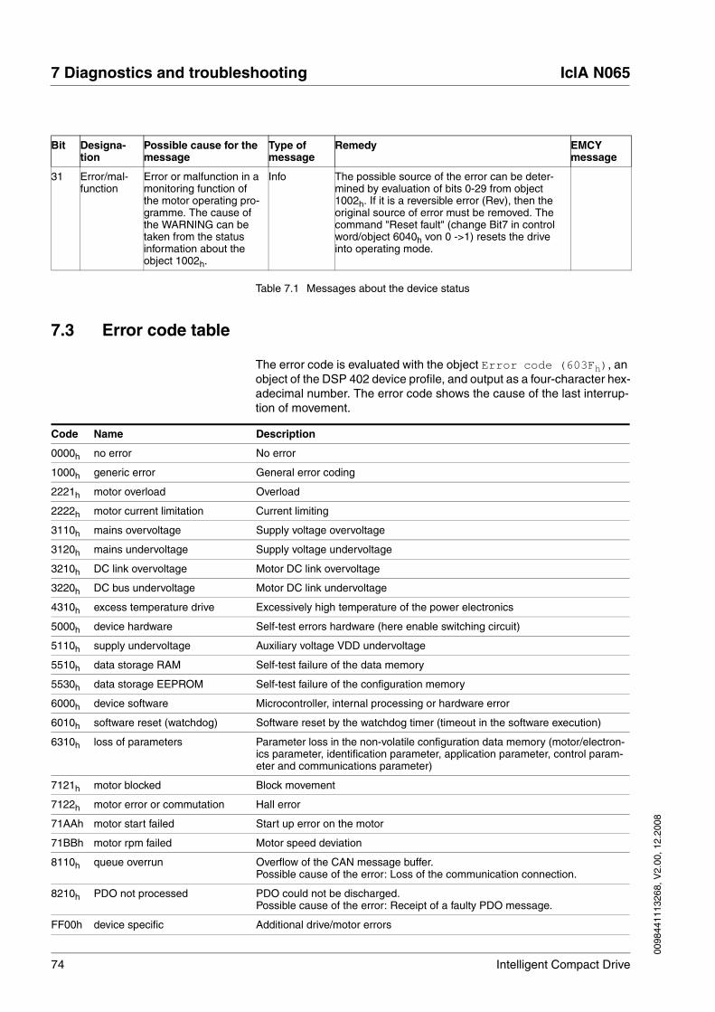
74 Intelligent Compact Drive
7 Diagnostics and troubleshooting IclA N065
0098
4411
1326
8, V
2.00
, 12.
2008
Table 7.1 Messages about the device status
7.3 Error code table
The error code is evaluated with the object Error code (603Fh), an object of the DSP 402 device profile, and output as a four-character hex-adecimal number. The error code shows the cause of the last interrup-tion of movement.
31 Error/mal-function
Error or malfunction in a monitoring function of the motor operating pro-gramme. The cause of the WARNING can be taken from the status information about the object 1002h.
Info The possible source of the error can be deter-mined by evaluation of bits 0-29 from object 1002h. If it is a reversible error (Rev), then the original source of error must be removed. The command "Reset fault" (change Bit7 in control word/object 6040h von 0 ->1) resets the drive into operating mode.
Bit Designa-tion
Possible cause for the message
Type of message
Remedy EMCY message
Code Name Description
0000h no error No error
1000h generic error General error coding
2221h motor overload Overload
2222h motor current limitation Current limiting
3110h mains overvoltage Supply voltage overvoltage
3120h mains undervoltage Supply voltage undervoltage
3210h DC link overvoltage Motor DC link overvoltage
3220h DC bus undervoltage Motor DC link undervoltage
4310h excess temperature drive Excessively high temperature of the power electronics
5000h device hardware Self-test errors hardware (here enable switching circuit)
5110h supply undervoltage Auxiliary voltage VDD undervoltage
5510h data storage RAM Self-test failure of the data memory
5530h data storage EEPROM Self-test failure of the configuration memory
6000h device software Microcontroller, internal processing or hardware error
6010h software reset (watchdog) Software reset by the watchdog timer (timeout in the software execution)
6310h loss of parameters Parameter loss in the non-volatile configuration data memory (motor/electron-ics parameter, identification parameter, application parameter, control param-eter and communications parameter)
7121h motor blocked Block movement
7122h motor error or commutation Hall error
71AAh motor start failed Start up error on the motor
71BBh motor rpm failed Motor speed deviation
8110h queue overrun Overflow of the CAN message buffer. Possible cause of the error: Loss of the communication connection.
8210h PDO not processed PDO could not be discharged. Possible cause of the error: Receipt of a faulty PDO message.
FF00h device specific Additional drive/motor errors

0098
4411
1326
8, V
2.00
, 12.
2008
IclA N065 7 Diagnostics and troubleshooting
Intelligent Compact Drive 75
Table 7.2 Error codes
FF01h emergency stop Hardware enable signal = Low - drive has been stopped
FF03h negative limit switch Negative end position sensor run over
FF04h positive limit switch Positive end position sensor run over
FF10h general application Application: general error
FF11h illegal mode application Application: invalid operating mode
FF12h illegal parameter application Application: invalid parameter value
FF13h position value application Application: invalid position value
FF14h usrerr poslim Application: invalid position memory
FF15h communication (NMT) Communication error for NMT
FF20h general drive controller Motor control: general error
FF21h power drive enabled Motor control: controllers not ready
FF22h no reference Motor control: Drive is not referenced
FF23h drive moves Motor control: Drive not at standstill
FF24h illegal mode drive controller Motor control: invalid operating mode
FF25h illegal parameter drive controller Motor control: invalid parameter value
FF26h parameter too low Motor control: parameter value too low
FF27h parameter too high Motor control: parameter value too large
FF28h position not accepted Motor control: position not accepted/processed
FF29h external force Effect of an external force
FF2Ah position overrun error Drive has not reached its target position due to the effect of an external force
FF2Bh velocity exceeded Drive was accelerated to above its maximum rpm through the action of an external force
FF30h illegal homing method Illegal homing method
FF33h negative limit switch active Drive standing at the negative end position sensor
FF34h positive limit switch active Drive standing at the positive end position sensor
FF35h negative limit switch disabled Negative end position sensor disabled
FF36h positive limit switch disabled Positive end position sensor disabled
FF37h home switch disabled Reference sensor disabled
FF83h drive at target position Drive at setpoint
Code Name Description

76 Intelligent Compact Drive
7 Diagnostics and troubleshooting IclA N065
0098
4411
1326
8, V
2.00
, 12.
2008

0098
4411
1326
8, V
2.00
, 12.
2008
IclA N065 8 Accessories and spare parts
Intelligent Compact Drive 77
8 Accessories and spare parts
8.1 Accessories
Source commissioning software The latest version of the commissioning software is available for down-load from the internet:
http://www.schneider-electric-motion.com
Cable Supplier recommendations:
• Hans Turck GmbH & Co. KGwww.turck.com
• Franz Binder GmbH & Co. elektrische Bauelemente KGwww.binder-connector.de
• PHOENIX CONTACT GmbH & Co. KGwww.phoenixcontact.com
• Lumberg Automationwww.lumberg-automation.com
Signal interface Supplier recommendations:
• FCT electronic GmbHwww.fct-electronic.de
Source product manuals The current product manuals are available for download from the Inter-net.http://www.schneider-electric-motion.com
Designation Order number
Braking Resistor Controller UBC60 ACC3EA001

78 Intelligent Compact Drive
8 Accessories and spare parts IclA N065
0098
4411
1326
8, V
2.00
, 12.
2008

0098
4411
1326
8, V
2.00
, 12.
2008
IclA N065 9 Service, maintenance and disposal
Intelligent Compact Drive 79
9 Service, maintenance and disposal
You cannot carry out repairs yourself. The repair should only be carried out by a certified customer service organisation. No warranty or liability is accepted for repairs made by the customer.
9.1 Service address
If you cannot resolve the fault yourself please contact your appointed sales partner. Have the following details available:
• Type plate (Type, identification number, serial number, DOM, ...)
• Type of fault (possibly with flash code or fault number)
• Previous and concurrent conditions
• Your own ideas regarding the cause of the fault
Include this information if you return the product for inspection or repair.
If you have any questions please contact your local dealer. Your dealer will be happy to give you the name of a customer service outlet in your area.
9.2 Maintenance
The product is maintenance free.
@ CAUTIONDestruction of system components and loss of control monitor-ing
Excessive currents can be created at the signal connections if the negative connection to the controller supply voltage is interrupted.
• Do not interrupt the negative connection between power supply unit and load with a fuse or switch
• Check for correct connection before switching on.
• Never connect the controller supply voltage or change its wiring while there is supply voltage present.
Failure to follow these instructions can result in injury or equip-ment damage.

80 Intelligent Compact Drive
9 Service, maintenance and disposal IclA N065
0098
4411
1326
8, V
2.00
, 12.
2008
9.3 Replacing units
Observe the following procedure when changing the devices.
� Store all parameter settings using the commissioning software on your PC.
� Switch off all supply voltages. Make sure that power is no longer connected (safety instructions).
� Label all connections and remove the product.
� Note the identification number and the serial number from the prod-uct nameplate for later identification.
� Install the new product as specified in chapter 4 "Installation"
� Carry out commissioning as described in Chapter 5 "Commission-ing"
@ WARNINGUnexpected behaviour
The behaviour of the drive system is governed by numerous stored data or settings. Unsuitable settings or data may trigger unexpected movements or reactions to signals and disable monitoring functions.
• Do not operate a drive system with unknown settings or data.
• Check the stored data or settings.
• When commissioning carefully run tests for all operating statuses and fault cases.
• Check the functions after replacing the product and also after making changes to the settings or data.
• Only start the system if there are no persons or materials in the danger zone and the system can be operated safely.
Failure to follow these instructions can result in death, serious injury or equipment damage.

0098
4411
1326
8, V
2.00
, 12.
2008
IclA N065 9 Service, maintenance and disposal
Intelligent Compact Drive 81
9.4 Shipping, storage, disposal
Removal Removal procedure:
� Switch off the power supply.
� Disconnect the power supply.
� Pull out all plugs.
� Remove the product from the system.
Shipping The product must be protected against shocks during transport. Use the original packaging for this purpose.
Storage Store the product only under the specified, approved environmental conditions for room temperature and humidity.Protect the product against dust and dirt.
Disposal The product consists of various materials that can be recycled and must be disposed of separately. Dispose of the product in accordance with lo-cal regulations.

82 Intelligent Compact Drive
9 Service, maintenance and disposal IclA N065
0098
4411
1326
8, V
2.00
, 12.
2008

0098
4411
1326
8, V
2.00
, 12.
2008
IclA N065 10 Glossary
Intelligent Compact Drive 83
10 Glossary
10.1 Units and conversion tables
The value in the specified unit (left column) is calculated for the desired unit (top row) with the formula (in the field).
Example: conversion of 5 metres [m] to yards [yd]5 m / 0.9144 = 5.468 yd
10.1.1 Length
10.1.2 Mass
10.1.3 Force
10.1.4 Power
in ft yd m cm mm
in - / 12 / 36 * 0.0254 * 2.54 * 25.4
ft * 12 - / 3 * 0.30479 * 30.479 * 304.79
yd * 36 * 3 - * 0.9144 * 91.44 * 914.4
m / 0.0254 / 0.30479 / 0.9144 - * 100 * 1000
cm / 2.54 / 30.479 / 91.44 / 100 - * 10
mm / 25.4 / 304.79 / 914.4 / 1000 / 10 -
lb oz slug kg g
lb - * 16 * 0.03108095 * 0.4535924 * 453.5924
oz / 16 - * 1.942559*10-3 * 0.02834952 * 28.34952
slug / 0.03108095 / 1.942559*10-3 - * 14.5939 * 14593.9
kg / 0.453592370 / 0.02834952 / 14.5939 - * 1000
g / 453.592370 / 28.34952 / 14593.9 / 1000 -
lb oz p dyne N
lb - * 16 * 453.55358 * 444822.2 * 4.448222
oz / 16 - * 28.349524 * 27801 * 0.27801
p / 453.55358 / 28.349524 - * 980.7 * 9.807*10-3
dyne / 444822.2 / 27801 / 980.7 - / 100*103
N / 4.448222 / 0.27801 / 9.807*10-3 * 100*103 -
HP W
HP - * 745.72218
W / 745.72218 -
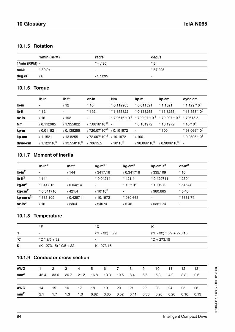
84 Intelligent Compact Drive
10 Glossary IclA N065
0098
4411
1326
8, V
2.00
, 12.
2008
10.1.5 Rotation
10.1.6 Torque
10.1.7 Moment of inertia
10.1.8 Temperature
10.1.9 Conductor cross section
1/min (RPM) rad/s deg./s
1/min (RPM) - * π / 30 * 6
rad/s * 30 / π - * 57.295
deg./s / 6 / 57.295 -
lb·in lb·ft oz·in Nm kp·m kp·cm dyne·cm
lb·in - / 12 * 16 * 0.112985 * 0.011521 * 1.1521 * 1.129*106
lb·ft * 12 - * 192 * 1.355822 * 0.138255 * 13.8255 * 13.558*106
oz·in / 16 / 192 - * 7.0616*10-3 * 720.07*10-6 * 72.007*10-3 * 70615.5
Nm / 0.112985 / 1.355822 / 7.0616*10-3 - * 0.101972 * 10.1972 * 10*106
kp·m / 0.011521 / 0.138255 / 720.07*10-6 / 0.101972 - * 100 * 98.066*106
kp·cm / 1.1521 / 13.8255 / 72.007*10-3 / 10.1972 / 100 - * 0.9806*106
dyne·cm / 1.129*106 / 13.558*106 / 70615.5 / 10*106 / 98.066*106 / 0.9806*106 -
lb·in2 lb·ft2 kg·m2 kg·cm2 kp·cm·s2 oz·in2
lb·in2 - / 144 / 3417.16 / 0.341716 / 335.109 * 16
lb·ft2 * 144 - * 0.04214 * 421.4 * 0.429711 * 2304
kg·m2 * 3417.16 / 0.04214 - * 10*103 * 10.1972 * 54674
kg·cm2 * 0.341716 / 421.4 / 10*103 - / 980.665 * 5.46
kp·cm·s2 * 335.109 / 0.429711 / 10.1972 * 980.665 - * 5361.74
oz·in2 / 16 / 2304 / 54674 / 5.46 / 5361.74 -
°F °C K
°F - (°F - 32) * 5/9 (°F - 32) * 5/9 + 273.15
°C °C * 9/5 + 32 - °C + 273,15
K (K - 273.15) * 9/5 + 32 K - 273.15 -
AWG 1 2 3 4 5 6 7 8 9 10 11 12 13
mm2 42.4 33.6 26.7 21.2 16.8 13.3 10.5 8.4 6.6 5.3 4.2 3.3 2.6
AWG 14 15 16 17 18 19 20 21 22 23 24 25 26
mm2 2.1 1.7 1.3 1.0 0.82 0.65 0.52 0.41 0.33 0.26 0.20 0.16 0.13

0098
4411
1326
8, V
2.00
, 12.
2008
IclA N065 10 Glossary
Intelligent Compact Drive 85
10.2 Terms and Abbreviations
Actual position Current absolute or relative position of moving components in the drive system.
Address Memory location which can be accessed by its unique number. See also Slave address.
CAN (Controller Area Network), standardized open Fieldbus over which the drives and other devices from different manufacturers communicate with one another.
CANopen Device and manufacturer-independent description language for com-munication in the CAN bus
DC Direct current
DC bus Electric circuit that generates the direct current required to operate the motor and supplies the required energy to the power electronics. The DC bus acts as a buffer for energy fed back by the motor.
Direction of rotation Rotation of the motor shaft in a positive or negative direction of rotation. A positive direction of rotation is defined as the motor shaft rotating clockwise as the observer faces the end of the protruding shaft.
Drive system System consisting of controller, power electronics and motor.
EC European Community
EC motor Electronically commutated motor
EDS Electronic Data Sheet Contains the technical data for the motor and gearbox and is loaded in the factory.
EMC Electromagnetic compatibility.
EU European Union
Fieldbus A bus optimised for data transmission between field devices. A Fieldbus is “open”, meaning that it is not proprietary (not supported by only one manufacturer). The parameter settings of the drive system can be called and modified via the Fieldbus, inputs can be monitored and outputs con-trolled and diagnosis and error monitoring functions enabled.
Hall sensor Sensor for determining position
Holding brake brake that only prevents the motor from rotating without power after it has stopped (e.g. a vertikal-axis lowering). It must not be used as a serv-ice brake for braking motion.
I/O Inputs/Outputs
I2t-monitoring Predictive temperature monitoring. The expected temperature rise of unit components is calculated in advance on the basis of the motor cur-rent. If a limit value is exceeded, the drive system reduces the motor cur-rent.
Idx Index value of a parameter
Inc Increment
Limit switch Switch that signals an overrun of the permissible travel range.
LSS Layer setting services, setting services of the CAN application layers
M Motor

86 Intelligent Compact Drive
10 Glossary IclA N065
0098
4411
1326
8, V
2.00
, 12.
2008
Master Active bus user that controls the data traffic in the network.
Node Guarding Monitoring function with slave at an interface for cyclic communication.
node ID Node address assigned to a device on the network.
Parameter Device functions and values that can be set and called by the user.
PC Personal Computer
PDO Process Data Object
PELV Protective Extra Low Voltage, functional low voltage with safe isolation.
PLC Programmable Logic Controller
power electronic system This is the unit that controls the motor. The power electronics generate currents for controlling the motor in accordance with the positioning sig-nals from the control unit.
Protection class The protection class is a standardised specification for electrical equip-ment that describes the protection against the ingress of foreign bodies and water (for example, IP20).
Protocol Guideline that specifies the format required for transmitting data.
Quick Stop Quick stop, function used to provide quick braking of the motor via a command or in the event of a fault.
Register Memory range of specified size (generally 8, 16 or 32 bits) for temporary storage of data transmitted from one system unit to another.
SDO Service Data Object
Slave Passive bus device that receives control commands and provides data to the master.
Slave address Targeted communications between master and slave is only possible with the assignment of unique addresses.
Software limit switch Limitation of the movement range in both directions of motion, settings are determined specifically with the application. A positioning is possible only within the working range.
Timeout Error caused by exceeding the maximum allowable time between query and response of devices.
Watchdog Equipment that monitors cyclic basic functions in the drive system. Power electronics and outputs are switched off in the event of error.

0098
4411
1326
8, V
2.00
, 12.
2008
IclA N065 11 Index
Intelligent Compact Drive 87
11 Index
AAbbreviations 85ABORT 69Accessories 77Accessories and spare parts 77Accessories for networking 48Address
check 67
BBaud rate
check 67Block movement 65
CCable specifications
control inputs for manual operation 46Enable connection 47equipotential bonding conductor connection 42power supply 45, 50
CE mark 16Characteristic curve
IclA N065 DC024 26Characteristic curves
IclA N065 U- with angled wormgear 32IclA N065 V- with spur wheel gears 28
Checkaddress 67baud rate 67
Circular plug-in connectorassignment of output socket 48
circular plug-in connectorassignment of input plugs 48
Commissioning 53steps 55
Commissioning software 56, 77features 56requirements 56
Communication configuration 60Commutation errors 65Components and interfaces 11Configuration mode (for setting parameters) 60Connection
control inputs for manual operation 46equipotential bonding conductor connection 42power supply 45
Control inputs for manual operationcable specifications 46connection 46
Current limiting 63

88 Intelligent Compact Drive
11 Index IclA N065
0098
4411
1326
8, V
2.00
, 12.
2008
DDanger classes 20Declaration of conformity 17Design data
IclA N065 DC024 25IclA N065 U- with angled wormgear 31IclA N065 V- with spur wheel gear 27
Diagnostics 67Directives and standards 16Disposal 79, 81Documentation and literature references 15
EElectrical installation 41Electronic Data Sheet 13Electronic log-book 13, 65EMC 37Enable connection
cable specifications 47Enable function 61Environmental conditions 23Equipotential bonding conductor connection
cable specifications 42equipotential bonding conductor connection
connection 42Equipotential bonding conductors 38Error code
table 74Error diagnosis
connections to field-bus mode 67function test on fieldbus 67
FFatal error (fatal) 69Function test
on fieldbus 67Functions 60
GGlossary 83
HHall sensor errors 65Homing 60
IIclA
special features 10Installation
electrical 41Function test 51mechanical installation 39
Installation material

0098
4411
1326
8, V
2.00
, 12.
2008
IclA N065 11 Index
Intelligent Compact Drive 89
Field bus connection 48Installation, electrical
Connecting supply voltage 44Intended use 19Interruption of movement
cause 74Introduction 9
LLMT service 60
MMaintenance 79Manual movement test 51Manual operation via fieldbus 59Manual operation via signals 59manuals 15, 77Message 69Message objects 68
EMCY(80h+ node ID) 68error code (603Fh) 68error register (1001h) 68status word (6041h) 68
Messages on the device status 69Monitoring functions 22, 62
block movement 65commutation/Hall sensor errors 65current limiting 63electronic log-book 65outside acceleration 65overload 63self-test at Power On 62speed deviation 64starting error 64temperature 64voltages 64watchdog 66
NNetwork messages
after switching on 67Network operation
not possible 67
OOperating functions
communication configuration 60Operating modes 59
homing 60manual operation via fieldbus 59manual operation via signals 59positioning mode 60speed control mode 60
Operation 59

90 Intelligent Compact Drive
11 Index IclA N065
0098
4411
1326
8, V
2.00
, 12.
2008
Outside acceleration 65Overload 63Overview
all connections 41
PPositioning mode 60Positioning mode, operating mode 60Power supply
cable specifications 45, 50connection 45
product manuals 15, 77Protection classes 40
QQualifications, personnel 19
RReversible error (Rev) 69
SScope of supply 9SDO
error message 69Self-test at Power On 62Service 79Service address 79Shipping 81Source
Commissioning software 56, 77product manuals 15, 77
Speed control mode 60Speed control mode, operating mode 60Speed deviation 64Starting error 64Storage 81Supply voltage
connecting 44System checks 51
TTechnical data 23Temperature 64Terms 85Testing fieldbus wiring 51Troubleshooting 67Type code 14
UUnit overview 10Units and conversion tables 83

0098
4411
1326
8, V
2.00
, 12.
2008
IclA N065 11 Index
Intelligent Compact Drive 91
VVoltages 64
WWARNING (Warn) 69Watchdog 66

92 Intelligent Compact Drive
11 Index IclA N065
0098
4411
1326
8, V
2.00
, 12.
2008