intelligent ground vehicle: pablobot - igvc.org · obstacle course utilizing path finding...
TRANSCRIPT
1
INTELLIGENT GROUND VEHICLE: PABLOBOT
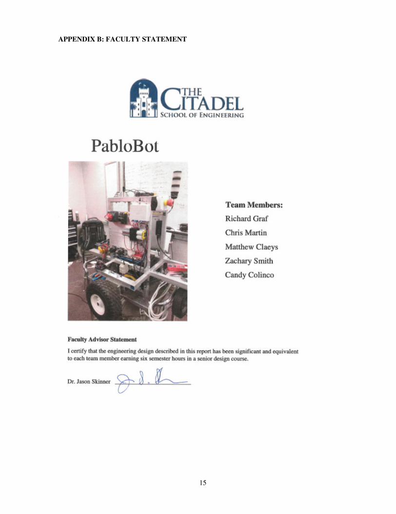
The Citadel The Military College of South Carolina Richard Graf,* Paul “Chris” Martin,† Matthew Claeys,‡ Candy Colinco§, Zachary Smith**
Dr. Jason Skinner([email protected])
The annual Intelligent Ground Vehicle Competition (IGVC) allows for students on the undergraduate and graduate level to design, build, and test intelligent ground vehicles in a competitive environment. The IGVC is a three part compe-tition consisting of a vehicle design, autonomous navigation through an unknown obstacle course and an interoperability challenge that requires the utilization of the JAUS communication protocol. In the past, the Citadel has competed in the prestigious competition with varying degrees of success. The 2016 entrant in the IGVC competition from the Citadel’s Electrical Engineering department will be Team Pablo and their PabloBot. PabloBot is the result of significant design changes in both mechanical and software systems. Through the services of the Mechanical engineering department, the chassis was rebuilt completely, compris-ing of a two wheeled, DC powered, forklift style differential drive vehicle. The software system moved from the Windows based Labview platform to the Linux based Robot Operating System (ROS) and the image processing library OpenCV. Through integrated sensory hardware, the vehicle navigates through an unknown obstacle course utilizing path finding algorithms and obstacle mapping to achieve a specified goal.
INTRODUCTION
The desire and popularity of intelligent, autonomous ground vehicles has increased recently in our modern world, especially in the fields of manufacturing, business, home automation, city streets, and the military applications. Whether it is remote planetary exploration or the need to increase transportation efficiency, ground vehicles can operate without human interaction to pro-vide solutions to these problems. The IGVC allows for students on the undergraduate and graduate level to design, build, and test intelligent ground vehicles in a competitive environment. “It is multidisciplinary, theory-based, hands-on, team implemented, outcome assessed, and based on product realization.”1 Additionally, designing a vehicle for entry into the competition provides an excellent platform for an engineering team to fulfill its capstone project requirements. Team Pablo’s entrant, PabloBot, is the result of the two semester design course required for completion of an electrical engineering degree from The Citadel, The Military College of South Carolina.
* The Citadel School of Engineering [email protected] † The Citadel School of Engineering [email protected] ‡ The Citadel School of Engineering [email protected] § The Citadel School of Engineering [email protected] ** The Citadel School of Engineering [email protected]
2
DESIGN PROCESS
The team began the design process by meeting with members of the previous year’s team and
discussing the areas of concern that existed with the current platform. The vehicle’s mechanical
and software systems were then evaluated and after discussion with the faculty, problematic areas
were targeted and used as reference points to design from. Mechanically, the existing chassis was
determined to be too large in terms of footprint for the tight maneuverability required for success-
fully navigating an obstacle course. For software, the largest area of concern was its lack of speed
and responsiveness, leading to a vehicle that was slow in its decision making process, which re-
sulted in slow navigational speed. After considering these concerns, a complete rebuild of both the
mechanical and software systems was determined to be the best course of action. Concerns of
chassis size could only be addressed by redesigning and constructing a new chassis. Rebuilding
the software platform allowed for greater control over its functionality, speed, and responsiveness,
while avoiding the time sink of learning and adapting to a system that was designed outside of the
team’s control.
Team Pablo had the unique opportunity to utilize the services of the Mechanical Engineering
design team, Atlas Engineering. Atlas Engineering was comprised of three senior engineering stu-
dents from The Citadel’s Mechanical Engineering department and were tasked with PabloBot’s
chassis design and construction for their capstone design project. A typical business client rela-
tionship was established between Team Pablo and Atlas Engineering. After establishing the initial
design constraints, bi-weekly meetings were held so that design options, areas of concern, and
overall progress of the chassis construction could be discussed and addressed. Because most of the
mechanical concerns would be handled by Atlas Engineering, Team Pablo focused primarily on
the software and control systems. An outline of this design process can be seen in Table 1.
Phase
Requirements/Constraints 1
Mechanical/Software evaluation 2
OS/Software platforms 3
Sensory integration 4
Lane Detection/Image Processing 5
Localization/Motor Control 6
Objection avoidance/Path Planning/Mapping/Navigation 7
Final Integration 8
Testing 9
TABLE 1. PROJECT OUTLINE
3
MECHANICAL
Chassis
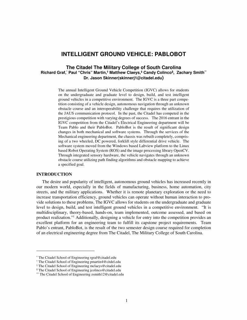
Three different chassis options, Forklift Chassis Platform (FCP), Zero Turn Lawn Mower
(ZTL), and Six Wheeler Chassis (SWC), were presented to team members by Team Atlas. After
evaluating the features of the different platforms, FCP offered the most favorable design features
and was chosen because it offered the simplest geometry while offering a robust platform to which
drivetrain components and electrical hardware could be mounted without compromising the quality
and strength of the chassis. The FCP design can be seen in figure 1. A key component to the FCP
design was the location of the drive wheels and stabilizing caster wheel. The previous platform
was constructed in similar fashion to the FCP, but with the drive wheels located on the rear of the
vehicle and the caster at the front. During initial tests with the existing platform, two significant
issues were determined with this wheel configuration. First, the vehicle was unable to rotate in
place at max motor commands due to the large moment arm created by the rear placed drive wheels
and the inertia required to overcome the heavily loaded caster wheel. Secondly, the loaded caster
wheel had the effect of steering the vehicle into undesired directions which lead to an unstable
system because of the constant correction and re-correction needed to achieve a desired heading.
The FCP’s center drive wheels, and lightly loaded rear caster wheel offered the best solution to the
torque and steering concerns seen in the previous year’s chassis.
Figure 1. Forklift Chassis Platform Design
4
Drivetrain
Several different methods of power transmission were investigated based on utilizing electric motors as the prime mover. Methods researched and discussed with Atlas Engineering included an internal combustion engine, hub motors, chain/belt drive with gearbox, and direct drive with gear box. Ultimately, direct drive with gear box was settled upon as the most favorable option for power transmission. The direct drive system minimized cost by retaining most of the components from the previous year’s drive system while retaining the simplicity of a differential drive steer-ing. The drivetrain is driven by two DC motors which utilize a 12V deep cycle battery for power and are interfaced to the existing 12.76:1 gearboxes. Locating the battery at the center lower por-tion of the chassis gives the vehicle a low center gravity which results in a stable system during angular acceleration.
Performance
Tests with the new chassis and drivetrain produced promising results. The vehicle was capa-ble of turning in place well within the motor command slot and had stable steering system that was largely unaffected by the rear placed caster wheel. Overall, the vehicle was much more re-sponsive and able to achieve a tighter turning radius compared to the chassis of the previous year’s team. Additionally, Team Atlas expected, based on motor specifications and expected chassis weight, that the min and max vehicle velocities would be within the IGVC rule constraints of 1 MPH and 5 MPH, respectively. Testing on the FCP platform showed that the velocity con-straints were met.
ELECTRICAL
Power
The vehicle’s main power system is supplied by a 12 VDC deep cycle marine battery that is
capable of supplying 80 amp hours of current draw. A 275 amp continuous draw rated master
switch connects the battery to the rest of the power system, and serves as the main means for con-
trolling power to the vehicle. The electrical system is, then, separated into 12 VDC and 5VDC
supply systems.
The 12 VDC system supplies power to the vehicle’s camera, motor system, safety indication
system, and USB hub. The motor system’s two Victor 888 motor controllers and two 2.5” CIM
motors are protected by a 120 amp circuit breaker. The camera, two PAC-80 isolation relays, and
Anker USB 3.0 hub are individually protected by DIN Rail mounted indicating fuse holders and
fuses. The separately powered USB hubs allows for related components to be powered separately
from the computer’s battery. This reduces the current draw on the battery and extends the expected
runtime. Apart from the right motor, all of the components for the 12 V system are mounted on
the vehicles left side wall which ensures that any potential magnetic noise from high current devices
does not interfere with the signaling function of the 5V system.
Two separate power rails, one from the Arduino’s UNO regulated power supply, and the other
from the USB hub’s 1.5 amp rated charge port, provide power to the 5V system components. A
JBtek 4 channel relay module, the quadrature counter, and encoders are powered through the Ar-
duino’s supply rail. The onboard 802.11 B/G router is powered though USB hub’s charge port.
Generating a supply rail independent of the Arduino’s regulated supply was investigated, but was
determined to be unnecessary given the protective polyfuse onboard the Arduino and its loaded 5V
stability.
5
Safety
The vehicle’s safety was designed and implemented based on IGVC’s safety2 constraints. The auto-mode light is flashed by a hardware flasher circuit that is relay controlled through a GPIO pin on the Arduino, which is software controlled by the vehicle’s GPS navigation node. Additionally, an Estop indication light was added, so that current state of the vehicle’s Estop circuit could be identified. Not being able to identify the state of the Estop circuit was problematic on numerous occasions during testing and became a safety concern when saturated PID controllers caused an unpredictable response from the vehicle.
The Estop circuit consists of Linear DXR-702 wireless receiver and manual Estop button that is wired in series with two isolation relays that sit in between the output of the motor controllers to the motors. The wireless receiver is controlled by a Linear DXT-21 wireless transmitter, and both Estop devices (wireless and manual), lock in the current state when actuated.
CPUROS Indigo on Ubuntu 14.10 LTS
OpenCV image processingIMU
GPS
LiDAR Camera
Arduino
Left H-Bridge
Right H-Bridge
Left
Motor
Right
Motor
Left
Encoder
Right
Encoder
USB Ethernet
USB
USB
XBOX
CONTROLER
USB
Hardware
Counter
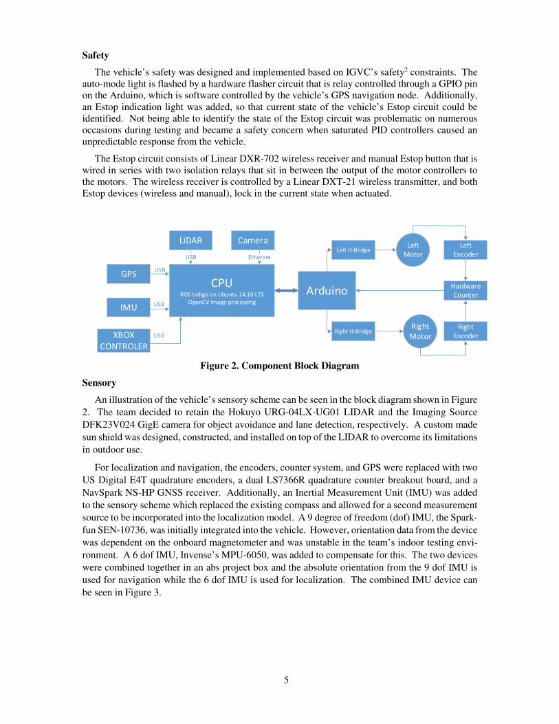
Figure 2. Component Block Diagram
Sensory
An illustration of the vehicle’s sensory scheme can be seen in the block diagram shown in Figure
2. The team decided to retain the Hokuyo URG-04LX-UG01 LIDAR and the Imaging Source
DFK23V024 GigE camera for object avoidance and lane detection, respectively. A custom made
sun shield was designed, constructed, and installed on top of the LIDAR to overcome its limitations
in outdoor use.
For localization and navigation, the encoders, counter system, and GPS were replaced with two
US Digital E4T quadrature encoders, a dual LS7366R quadrature counter breakout board, and a
NavSpark NS-HP GNSS receiver. Additionally, an Inertial Measurement Unit (IMU) was added
to the sensory scheme which replaced the existing compass and allowed for a second measurement
source to be incorporated into the localization model. A 9 degree of freedom (dof) IMU, the Spark-
fun SEN-10736, was initially integrated into the vehicle. However, orientation data from the device
was dependent on the onboard magnetometer and was unstable in the team’s indoor testing envi-
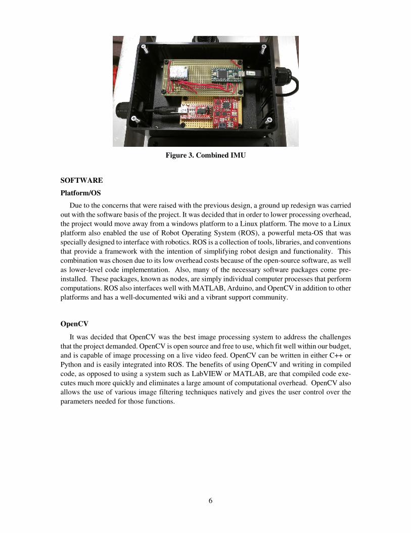
ronment. A 6 dof IMU, Invense’s MPU-6050, was added to compensate for this. The two devices
were combined together in an abs project box and the absolute orientation from the 9 dof IMU is
used for navigation while the 6 dof IMU is used for localization. The combined IMU device can
be seen in Figure 3.
6
Figure 3. Combined IMU
SOFTWARE
Platform/OS
Due to the concerns that were raised with the previous design, a ground up redesign was carried
out with the software basis of the project. It was decided that in order to lower processing overhead,
the project would move away from a windows platform to a Linux platform. The move to a Linux
platform also enabled the use of Robot Operating System (ROS), a powerful meta-OS that was
specially designed to interface with robotics. ROS is a collection of tools, libraries, and conventions
that provide a framework with the intention of simplifying robot design and functionality. This
combination was chosen due to its low overhead costs because of the open-source software, as well
as lower-level code implementation. Also, many of the necessary software packages come pre-
installed. These packages, known as nodes, are simply individual computer processes that perform
computations. ROS also interfaces well with MATLAB, Arduino, and OpenCV in addition to other
platforms and has a well-documented wiki and a vibrant support community.
OpenCV
It was decided that OpenCV was the best image processing system to address the challenges
that the project demanded. OpenCV is open source and free to use, which fit well within our budget,
and is capable of image processing on a live video feed. OpenCV can be written in either C++ or
Python and is easily integrated into ROS. The benefits of using OpenCV and writing in compiled
code, as opposed to using a system such as LabVIEW or MATLAB, are that compiled code exe-
cutes much more quickly and eliminates a large amount of computational overhead. OpenCV also
allows the use of various image filtering techniques natively and gives the user control over the
parameters needed for those functions.
7
Motor Control and Localization
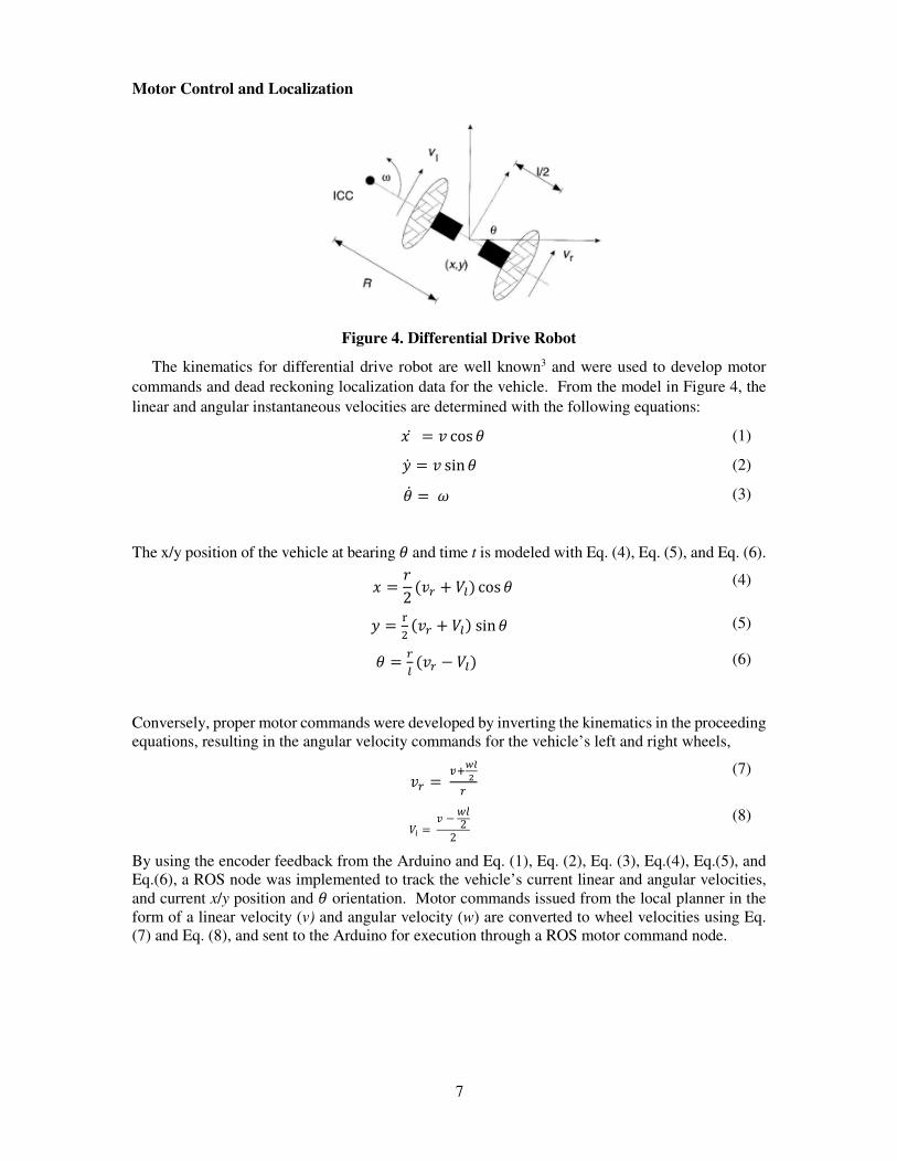
Figure 4. Differential Drive Robot
The kinematics for differential drive robot are well known3 and were used to develop motor
commands and dead reckoning localization data for the vehicle. From the model in Figure 4, the
linear and angular instantaneous velocities are determined with the following equations:
�� = � cos (1)
� = � sin (2)
� = (3)
The x/y position of the vehicle at bearing and time t is modeled with Eq. (4), Eq. (5), and Eq. (6).
� =�
2(�� + ��) cos (4)
=�
�(�� + ��)sin (5)
=�
�(�� − ��) (6)
Conversely, proper motor commands were developed by inverting the kinematics in the proceeding equations, resulting in the angular velocity commands for the vehicle’s left and right wheels,
�� =��
��
�
�
(7)
�� =� −
��2
2
(8)
By using the encoder feedback from the Arduino and Eq. (1), Eq. (2), Eq. (3), Eq.(4), Eq.(5), and Eq.(6), a ROS node was implemented to track the vehicle’s current linear and angular velocities, and current x/y position and orientation. Motor commands issued from the local planner in the form of a linear velocity (v) and angular velocity (w) are converted to wheel velocities using Eq. (7) and Eq. (8), and sent to the Arduino for execution through a ROS motor command node.
8
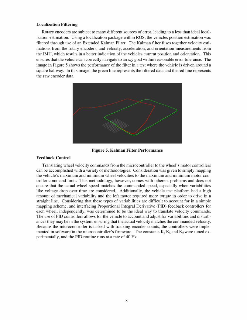
Localization Filtering
Rotary encoders are subject to many different sources of error, leading to a less than ideal local-
ization estimation. Using a localization package within ROS, the vehicles position estimation was
filtered through use of an Extended Kalman Filter. The Kalman filter fuses together velocity esti-
mations from the rotary encoders, and velocity, acceleration, and orientation measurements from
the IMU, which results in a better indication of the vehicles current position and orientation. This
ensures that the vehicle can correctly navigate to an x,y goal within reasonable error tolerance. The
image in Figure 5 shows the performance of the filter in a test where the vehicle is driven around a
square hallway. In this image, the green line represents the filtered data and the red line represents
the raw encoder data.
Figure 5. Kalman Filter Performance
Feedback Control
Translating wheel velocity commands from the microcontroller to the wheel’s motor controllers can be accomplished with a variety of methodologies. Consideration was given to simply mapping the vehicle’s maximum and minimum wheel velocities to the maximum and minimum motor con-troller command limit. This methodology, however, comes with inherent problems and does not ensure that the actual wheel speed matches the commanded speed, especially when variabilities like voltage drop over time are considered. Additionally, the vehicle test platform had a high amount of mechanical variability and the left motor required more torque in order to drive in a straight line. Considering that these types of variabilities are difficult to account for in a simple mapping scheme, and interfacing Proportional Integral Derivative (PID) feedback controllers for each wheel, independently, was determined to be the ideal way to translate velocity commands. The use of PID controllers allows for the vehicle to account and adjust for variabilities and disturb-ances they may be in the system, ensuring that the actual velocity matches the commanded velocity. Because the microcontroller is tasked with tracking encoder counts, the controllers were imple-mented in software in the microcontroller’s firmware. The constants Kp Ki, and Kd were tuned ex-perimentally, and the PID routine runs at a rate of 40 Hz.
9
Lane Detection
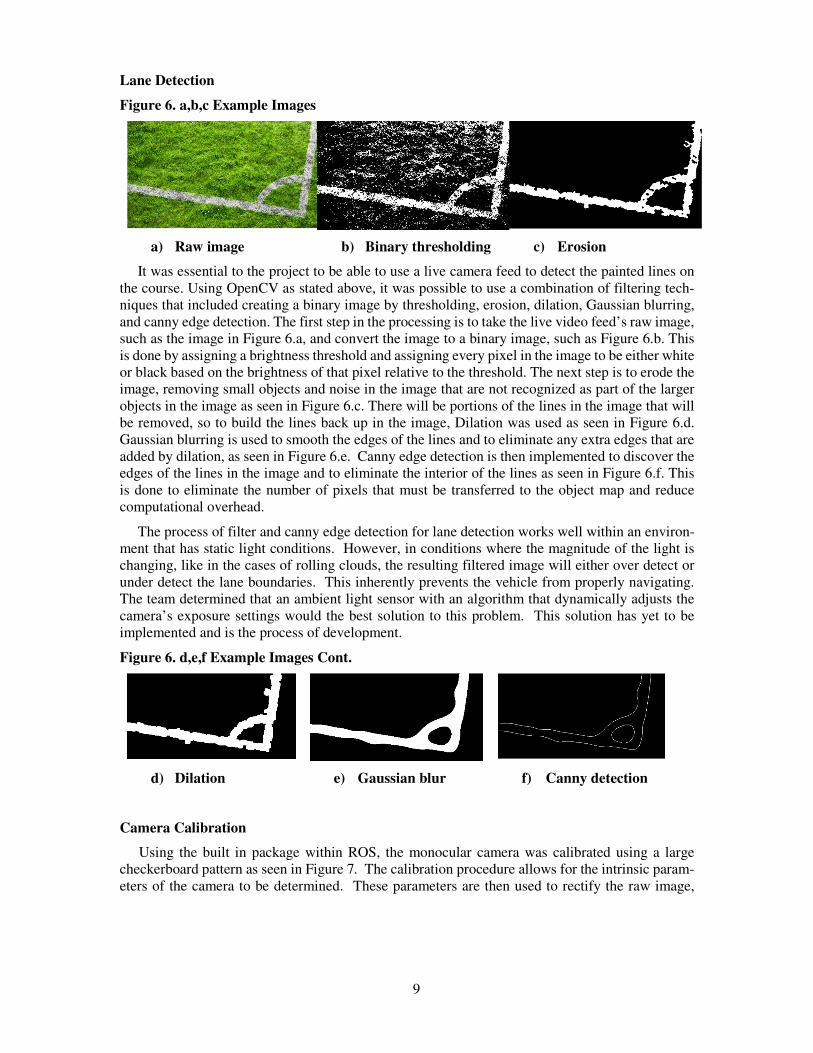
Figure 6. a,b,c Example Images
a) Raw image b) Binary thresholding c) Erosion
It was essential to the project to be able to use a live camera feed to detect the painted lines on the course. Using OpenCV as stated above, it was possible to use a combination of filtering tech-niques that included creating a binary image by thresholding, erosion, dilation, Gaussian blurring, and canny edge detection. The first step in the processing is to take the live video feed’s raw image, such as the image in Figure 6.a, and convert the image to a binary image, such as Figure 6.b. This is done by assigning a brightness threshold and assigning every pixel in the image to be either white or black based on the brightness of that pixel relative to the threshold. The next step is to erode the image, removing small objects and noise in the image that are not recognized as part of the larger objects in the image as seen in Figure 6.c. There will be portions of the lines in the image that will be removed, so to build the lines back up in the image, Dilation was used as seen in Figure 6.d. Gaussian blurring is used to smooth the edges of the lines and to eliminate any extra edges that are added by dilation, as seen in Figure 6.e. Canny edge detection is then implemented to discover the edges of the lines in the image and to eliminate the interior of the lines as seen in Figure 6.f. This is done to eliminate the number of pixels that must be transferred to the object map and reduce computational overhead.
The process of filter and canny edge detection for lane detection works well within an environ-ment that has static light conditions. However, in conditions where the magnitude of the light is changing, like in the cases of rolling clouds, the resulting filtered image will either over detect or under detect the lane boundaries. This inherently prevents the vehicle from properly navigating. The team determined that an ambient light sensor with an algorithm that dynamically adjusts the camera’s exposure settings would the best solution to this problem. This solution has yet to be implemented and is the process of development.
Figure 6. d,e,f Example Images Cont.
d) Dilation e) Gaussian blur f) Canny detection
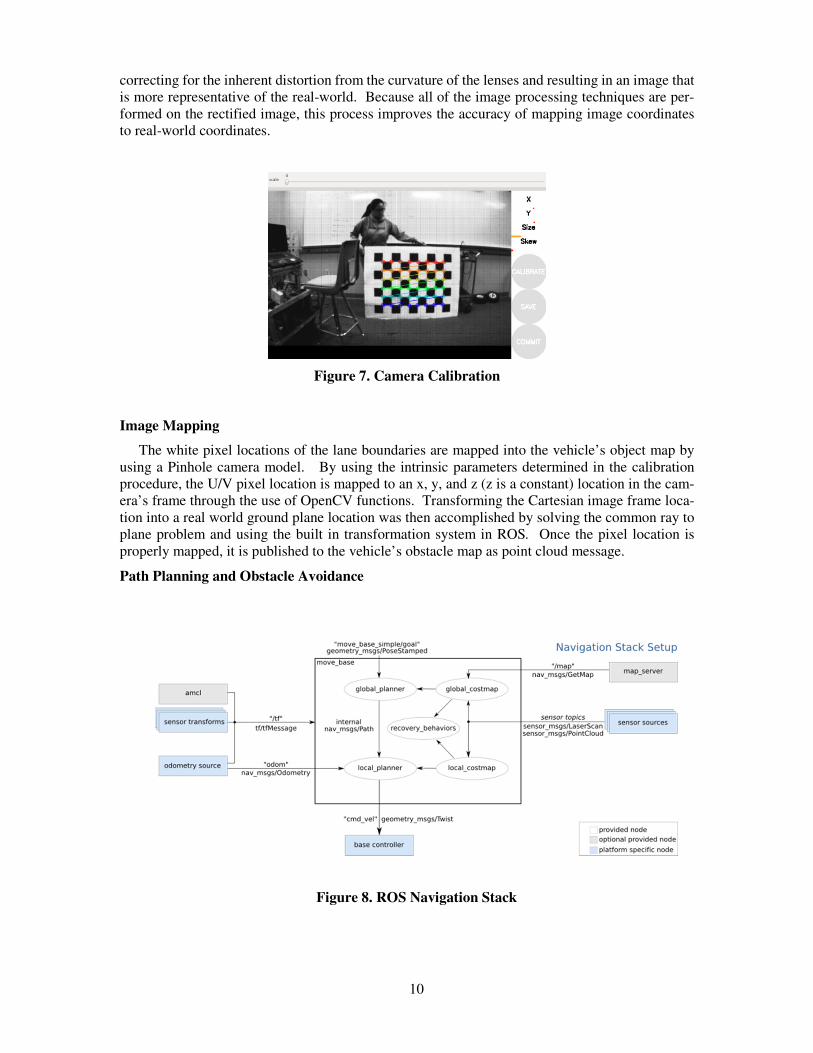
Camera Calibration
Using the built in package within ROS, the monocular camera was calibrated using a large checkerboard pattern as seen in Figure 7. The calibration procedure allows for the intrinsic param-eters of the camera to be determined. These parameters are then used to rectify the raw image,
10
correcting for the inherent distortion from the curvature of the lenses and resulting in an image that is more representative of the real-world. Because all of the image processing techniques are per-formed on the rectified image, this process improves the accuracy of mapping image coordinates to real-world coordinates.
Figure 7. Camera Calibration
Image Mapping
The white pixel locations of the lane boundaries are mapped into the vehicle’s object map by using a Pinhole camera model. By using the intrinsic parameters determined in the calibration procedure, the U/V pixel location is mapped to an x, y, and z (z is a constant) location in the cam-era’s frame through the use of OpenCV functions. Transforming the Cartesian image frame loca-tion into a real world ground plane location was then accomplished by solving the common ray to plane problem and using the built in transformation system in ROS. Once the pixel location is properly mapped, it is published to the vehicle’s obstacle map as point cloud message.
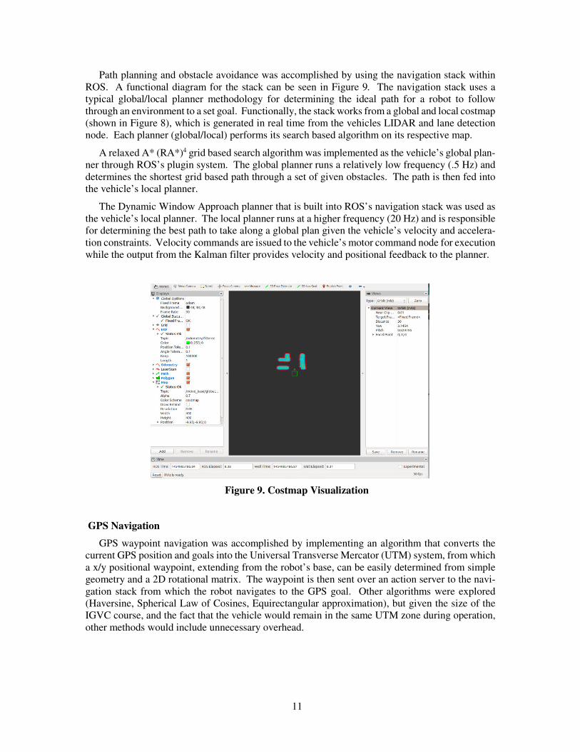
Path Planning and Obstacle Avoidance
Figure 8. ROS Navigation Stack
11
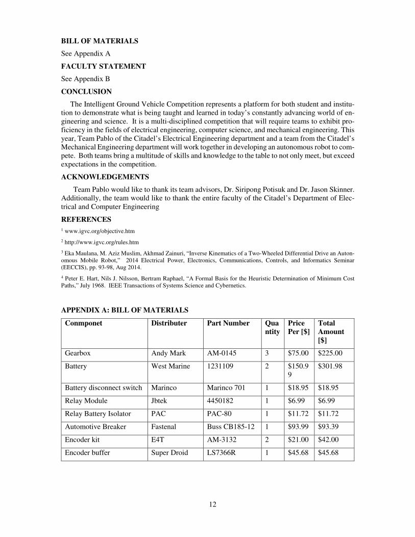
Path planning and obstacle avoidance was accomplished by using the navigation stack within ROS. A functional diagram for the stack can be seen in Figure 9. The navigation stack uses a typical global/local planner methodology for determining the ideal path for a robot to follow through an environment to a set goal. Functionally, the stack works from a global and local costmap (shown in Figure 8), which is generated in real time from the vehicles LIDAR and lane detection node. Each planner (global/local) performs its search based algorithm on its respective map.
A relaxed A* (RA*)4 grid based search algorithm was implemented as the vehicle’s global plan-ner through ROS’s plugin system. The global planner runs a relatively low frequency (.5 Hz) and determines the shortest grid based path through a set of given obstacles. The path is then fed into the vehicle’s local planner.
The Dynamic Window Approach planner that is built into ROS’s navigation stack was used as the vehicle’s local planner. The local planner runs at a higher frequency (20 Hz) and is responsible for determining the best path to take along a global plan given the vehicle’s velocity and accelera-tion constraints. Velocity commands are issued to the vehicle’s motor command node for execution while the output from the Kalman filter provides velocity and positional feedback to the planner.
Figure 9. Costmap Visualization
GPS Navigation
GPS waypoint navigation was accomplished by implementing an algorithm that converts the current GPS position and goals into the Universal Transverse Mercator (UTM) system, from which a x/y positional waypoint, extending from the robot’s base, can be easily determined from simple geometry and a 2D rotational matrix. The waypoint is then sent over an action server to the navi-gation stack from which the robot navigates to the GPS goal. Other algorithms were explored (Haversine, Spherical Law of Cosines, Equirectangular approximation), but given the size of the IGVC course, and the fact that the vehicle would remain in the same UTM zone during operation, other methods would include unnecessary overhead.
12
BILL OF MATERIALS
See Appendix A
FACULTY STATEMENT
See Appendix B
CONCLUSION
The Intelligent Ground Vehicle Competition represents a platform for both student and institu-tion to demonstrate what is being taught and learned in today’s constantly advancing world of en-gineering and science. It is a multi-disciplined competition that will require teams to exhibit pro-ficiency in the fields of electrical engineering, computer science, and mechanical engineering. This year, Team Pablo of the Citadel’s Electrical Engineering department and a team from the Citadel’s Mechanical Engineering department will work together in developing an autonomous robot to com-pete. Both teams bring a multitude of skills and knowledge to the table to not only meet, but exceed expectations in the competition.
ACKNOWLEDGEMENTS
Team Pablo would like to thank its team advisors, Dr. Siripong Potisuk and Dr. Jason Skinner. Additionally, the team would like to thank the entire faculty of the Citadel’s Department of Elec-trical and Computer Engineering
1 www.igvc.org/objective.htm
2 http://www.igvc.org/rules.htm
3 Eka Maulana, M. Aziz Muslim, Akhmad Zainuri, “Inverse Kinematics of a Two-Wheeled Differential Drive an Auton-omous Mobile Robot,” 2014 Electrical Power, Electronics, Communications, Controls, and Informatics Seminar (EECCIS), pp. 93-98, Aug 2014.
4 Peter E. Hart, Nils J. Nilsson, Bertram Raphael, “A Formal Basis for the Heuristic Determination of Minimum Cost Paths,” July 1968. IEEE Transactions of Systems Science and Cybernetics.
REFERENCES
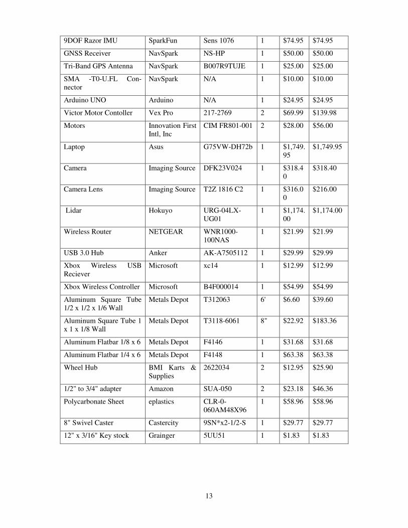
APPENDIX A: BILL OF MATERIALS
Conmponet Distributer Part Number Quantity
Price Per [$]
Total Amount [$]
Gearbox Andy Mark AM-0145 3 $75.00 $225.00
Battery West Marine 1231109 2 $150.99
$301.98
Battery disconnect switch Marinco Marinco 701 1 $18.95 $18.95
Relay Module Jbtek 4450182 1 $6.99 $6.99
Relay Battery Isolator PAC PAC-80 1 $11.72 $11.72
Automotive Breaker Fastenal Buss CB185-12 1 $93.99 $93.39
Encoder kit E4T AM-3132 2 $21.00 $42.00
Encoder buffer Super Droid LS7366R 1 $45.68 $45.68
13
9DOF Razor IMU SparkFun Sens 1076 1 $74.95 $74.95
GNSS Receiver NavSpark NS-HP 1 $50.00 $50.00
Tri-Band GPS Antenna NavSpark B007R9TUJE 1 $25.00 $25.00
SMA -T0-U.FL Con-nector
NavSpark N/A 1 $10.00 $10.00
Arduino UNO Arduino N/A 1 $24.95 $24.95
Victor Motor Contoller Vex Pro 217-2769 2 $69.99 $139.98
Motors Innovation First Intl, Inc
CIM FR801-001 2 $28.00 $56.00
Laptop Asus G75VW-DH72b 1 $1,749.95
$1,749.95
Camera Imaging Source DFK23V024 1 $318.40
$318.40
Camera Lens Imaging Source T2Z 1816 C2 1 $316.00
$216.00
Lidar Hokuyo URG-04LX-UG01
1 $1,174.00
$1,174.00
Wireless Router NETGEAR WNR1000-100NAS
1 $21.99 $21.99
USB 3.0 Hub Anker AK-A7505112 1 $29.99 $29.99
Xbox Wireless USB Reciever
Microsoft xc14 1 $12.99 $12.99
Xbox Wireless Controller Microsoft B4F000014 1 $54.99 $54.99
Aluminum Square Tube 1/2 x 1/2 x 1/6 Wall
Metals Depot T312063 6' $6.60 $39.60
Aluminum Square Tube 1 x 1 x 1/8 Wall
Metals Depot T3118-6061 8" $22.92 $183.36
Aluminum Flatbar 1/8 x 6 Metals Depot F4146 1 $31.68 $31.68
Aluminum Flatbar 1/4 x 6 Metals Depot F4148 1 $63.38 $63.38
Wheel Hub BMI Karts & Supplies
2622034 2 $12.95 $25.90
1/2" to 3/4" adapter Amazon SUA-050 2 $23.18 $46.36
Polycarbonate Sheet eplastics CLR-0-060AM48X96
1 $58.96 $58.96
8" Swivel Caster Castercity 9SN*x2-1/2-S 1 $29.77 $29.77
12" x 3/16" Key stock Grainger 5UU51 1 $1.83 $1.83
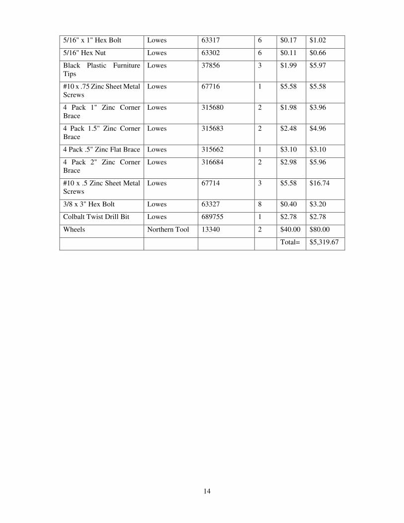
14
5/16" x 1" Hex Bolt Lowes 63317 6 $0.17 $1.02
5/16" Hex Nut Lowes 63302 6 $0.11 $0.66
Black Plastic Furniture Tips
Lowes 37856 3 $1.99 $5.97
#10 x .75 Zinc Sheet Metal Screws
Lowes 67716 1 $5.58 $5.58
4 Pack 1" Zinc Corner Brace
Lowes 315680 2 $1.98 $3.96
4 Pack 1.5" Zinc Corner Brace
Lowes 315683 2 $2.48 $4.96
4 Pack .5" Zinc Flat Brace Lowes 315662 1 $3.10 $3.10
4 Pack 2" Zinc Corner Brace
Lowes 316684 2 $2.98 $5.96
#10 x .5 Zinc Sheet Metal Screws
Lowes 67714 3 $5.58 $16.74
3/8 x 3" Hex Bolt Lowes 63327 8 $0.40 $3.20
Colbalt Twist Drill Bit Lowes 689755 1 $2.78 $2.78
Wheels Northern Tool 13340 2 $40.00 $80.00
Total= $5,319.67
15
APPENDIX B: FACULTY STATEMENT