intelligent meter based on zigbee wireless · pdf fileintelligent meter based on zigbee...
TRANSCRIPT

Sensors & Transducers, Vol. 155, Issue 8, August 2013, pp. 115-119
115
SSSeeennnsssooorrrsss &&& TTTrrraaannnsssddduuuccceeerrrsss
© 2013 by IFSAhttp://www.sensorsportal.com
Intelligent Meter Based on ZigBee Wireless Transmission
1 Xiongfei Fan, 2* Xiaodong Cheng, 3 Liping Wen, 4 Pengfei Fan 1 College of Electronic and Information Engineering, Inner Mongolia University,
Hohhot, 010021, China Tel.: +8613190602177
2 College of Electronic and Information Engineering, Inner Mongolia University, Hohhot, 010021, China Tel.: +8613484710308
3 College of Mechanical and Electrical Engineering, Inner Mongolia Agriculture University, Hohhot, 010018, China Tel.: +8615540977093
4 College of Computer Science, Inner Mongolia University, Hohhot, 010021, China Tel.: +8615248028624
E-mail: [email protected], [email protected], [email protected], [email protected]
Received: 23 May 2013 /Accepted: 12 August 2013 /Published: 20 August 2013 Abstract: Application of ZigBee technology combined with the power acquisition module and S3C2440 chip design a household electricity information acquisition and processing terminal system is described in the article. The system using the TI company Z-Stack protocol, and combines CC2530 RF chip to realize the remote meter reading, real-time data interaction, meter parameter setting and control commands sent, etc. Copyright © 2013 IFSA. Keywords: ModBus, ZigBee, CC2530, Intelligent, Meter.
1. Introduction
With the rapid development of computer technology and communication technology, various kinds of intelligent equipment with embedded systems incorporated in the people's life [1], has promoted the convergence of computing, communications, consumer electronics industry, and thus promotes the people's life and work dramatically changes.
In recent years, there is a shortage of electricity, power cuts and other phenomena in our country. In order to make reasonable use of electricity, our country began to implement ladder electricity price for residents, so that we can improve energy efficiency.
2. Composition of System The composition of the system structure as shown
in Fig. 1, the system consists of power acquisition module, ZigBee wireless transmission module and the terminal receiving device.
2.1. Power Acquisition Module The acquisition module uses RN8209G which is
produced by the RENERGY company as shown in Fig. 2, this module current measurement range is 5 mA to 30 A, voltage measuring range is AC76 ~ 260 V, output interface have two different types, named RS485 and TTL (5 V) respectively ,
Article number 1294

Sensors & Transducers, Vol. 155, Issue 8, August 2013, pp. 115-119
116
communication protocols using the ModBus protocol, baud rate from 1200 bps to 9600 bps, default to 4800 bps, real-time collection voltage, current, power factor, power and other parameters, the error is 0.1 %, operating temperature from -30 ° C to 70 ° C.
Fig. 1. The composition of the system structure.
Fig. 2. RN8209G acquisition module.
2.2. Wireless Communication Module
Wireless communications can use ZigBee, Bluetooth, WI-FI and infrared technology, etc. ZigBee technology is a short distance, low complexity, low power, low data rate, low-cost wireless network technology; it is a kind of technical scheme between wireless tag technology and Bluetooth technology, mainly used for the wireless connection from close range [2]. The outstanding characteristic of this technology is applied simple, long standby time, network capability, high reliability and low cost, our system uses the ZigBee CC2530 communication module as shown in Fig. 3, through the RS232 interface connected to the power acquisition module and ARM respectively, based on TI's official protocol stack to achieve power acquisition module with terminal wireless communication.
The software design of ZigBee module consists of the initialization and system management master program, clock module, power management, communication module [3]. The transmission of data and command is according to the ZigBee protocol to communicate. ZigBee sensor on the program design process as shown in Fig. 4, Based on the ZigBee
protocol Stack (Z -Stack), the control terminal of the ZigBee module coordinator as a wireless network device automatically complete the establishment of the network, ZigBee module with power acquisition module link as the terminal equipment (end device) by binding way to join the network, and initialization, data transmission and processing tasks news, etc.
Fig. 3. CC2530 communication module.
Fig. 4. ZigBee sensor on the program design process.
The establishment of a network: MeterDataApp_NwkState = DEV_INIT;
ZDOInitDevice() Network automatically created by the coordinator,
and the initialize of the device. Add a system task: const pTaskEventHandlerFntasksArr[] =
{macEventLoop,nwk_enent_loop,Hal_procesdsEvent,APS_event_loop}
The task initialization: void osalInit Tasks(void); Binding request: ZDApp_SendEndDeviceBindReq(); typedef struct{ZDEndDeviceBind_t ED1;uint8
state;......} Function body contains the binding nodes to join
the network relevant information, including the NWK address, IEEE address, EndPoint ID, etc [4].
If joining the network successfully, it returns: Assoc Cnf Success.
Data sent through call AF_DataRequest () function to achieve.

Sensors & Transducers, Vol. 155, Issue 8, August 2013, pp. 115-119
117
void MeterDataApp_SendTheMessage(void) {if(AF_DataRequest(&MeterDataApp_DstAddr,
(byte)osal_strlen(theMessageData)+1,(byte*)&theMessageData,&MeterDataApp_TransID......}
DstAddr: The address of the target node. Len: The length of data sent. TransID: Message ID, Play the role of the counter.
If the data request is sent successfully, the function returns: afStatus_SUCCESS.
Ubinding: Terminal equipment issued Ubinding request:
Unbind_req((uint16)0x0022). Exit the network: End_Device_Bind_rsp(End_Device_Bind_req|ZD
O_RESPONSE_BIT) The coordinator response to the terminal
equipment unbind request[5].
2.3. The Terminal Equipment
The terminal receiving device uses the 2440 ARM9 development board which is produced by the Friendly ARM company as shown in Fig. 5, it uses Samsung S3C2440 as the microprocessor, having an external memory (64 M SDRAM, 256 M NandFlash), LCD interface, 100M Ethernet RJ-45 interface, serial port, USB port, SD memory card interface, clock source, DE interface, audio output and other rich resources, the operating system can run WINDOWS CE, Linux, UCOSII embedded systems.
Fig. 5. S3C2440 ARM9 development board.
Mainly realized function is real-time receive and storage data which is collected by power module , the power acquisition module parameters Settings, and automatic alarm to remind the residents with electricity close to the ladder to adjust the price.
3. Communication Protocol of System
3.1. Introduction of the ModBus Protocol ModBus communication protocol is divided into
RTU protocol and ASCII protocol. ASCII protocol compared with RTU protocol have the start and end
tags, so when making process can be more convenient, and because the transmission of ASCII characters are visible, so when debugging is more intuitive. In addition, the LRC check is easy relatively. But every byte of RTU transmission ASCII data is to use two bytes to transfer, so that its transmission efficiency is lower. So, in general, if the need of transfer data is small ,we can consider to using the ASCII protocol, if they desired transfer large amount of data, it is best to use the RTU protocol, our system uses ModBus-RTU Transfer Protocol.
3.2. Communication Protocol
When communication command sent to the power acquisition module, conform to the corresponding address code (the system power acquisition module address is 01) device receives the command, and remove the address code, read the information, If there is no error, then execute the corresponding task; Then the result of execution is returned to the sender, The returned information includes address, function code, data, and error check code. If the error does not send any information, data frame format as shown in Table 1.
Table 1. Data frame format.
Address Code
Function Code
Data Area
Check Code
8 bits 8 bits N×8 bits 16 bits
Address Code: The address code is the first byte (8 bits) of the message frame from 0 to 255. This byte indicates that the slave address set by the user will receive the information sent by the host. Each slave must have a unique address code, only the corresponding address code from machine to respond to the loopback. When send information back from the machine, the address code indicates that the information from where.
Function Code: The host sends the function code tells the machine what tasks to execute. Table 2 lists the function code has a specific meaning and operation.
Table 2. Function code.
Code Meaning Operation
03 Read data Read the current register one or more binary values
06 Reset a single register
Write the binary value of set to a single register
06 Reset a single register
Write the binary value of set to a single register
Data Area: The data area contains the machine what action to perform, or send back information collected from the machine. These information may

Sensors & Transducers, Vol. 155, Issue 8, August 2013, pp. 115-119
118
be a numerical value or the reference address, etc. For example, the function code tells the machine to read the value of the register, the data area must contain the start address of the register to read and read length. For different machines, has a different address and data information.
Check Code: The sender or the receiver can use check code to judge whether receive information error. Sometimes, due to electronic noise or other information, minor changes will occur in the process of transmission, check code ensure that error messages do not work in the process of sending or receiving. So that increases the safety and efficiency of the system, error check adopts CRC-16 check code. RN8209G collected data are stored in the corresponding register inside real-time, the module effective register as shown in Table 3.
Table 3. RN8209G effective register.
Register address Function Description 0000H (read only) Model 1 value is 9000 0001H (read only) Model 2 value is B131H 0002H (read only) Voltage range 0003H (read only) Current range
0004H (readable and writable)
The default value is 0105 H. The default address is 01 H. The default format is 8, N, 1, 4800bps. Description: The 8 bits of high byte is the address, 1~127; The high 2 bits of low byte is the data; The low 4 bits of low byte is the baud rate: 3-1200 bps, 4-2400 bps, 5-4800 bps, 6-9600 bps.
0048H (read only) Voltage 0049H (read only) Current 004AH (read only) Active power 004BH (read only) High bits of electrical energy 004CH (read only) Low bits of electrical energy 004DH (read only) Power factor
3.3. Command Parsing
Send the command: 01 03 00 48 00 06 45 DE (Read 6 registers starting from 0048).
Receive Data: 01 03 0C 57 E4 09 D9 02 2D 00 00 03 40 03 D6 3F 17.
57 E4 corresponding 0048 register, that is the voltage: 0x57E4=22500, and then divided by 100 is equal to 225 V, each register data is 2 bytes, similarly according to the above formula can be derived the other data.
4. Design of Terminal Software
The software development of intelligent terminal communication module is based on Win CE 6.0 embedded operating system. Its architecture adopted independent programming language and Windows-compatible API way, ensure that Windows CE.net
components and ROM to adapt to the requirements of the limited storage space and a variety of chip [6]. Development of intelligent home appliance control terminal system, first of all, we need according to the hardware platform and applications to customize the Windows CE.net operating system kernel, development of intelligent handheld terminal application on the basis of complete custom operating system kernel, combined with underlying drivers of the chip, and design software of the intelligent meter. The intelligent control terminal of the system design as shown in Fig. 6 mainly includes three different parts: current parameter, ladder electricity price and historical curve.
Fig.6. The intelligent control terminal design.
The function of current parameter section is real-time to read the voltage, current, power factor, power, and data collected by the power module.
The function of ladder electricity section is to display the current ladder, electricity prices and the monthly electricity fee, when the month electrical energy close to the ladder adjust price then alarm to remind automatically, In addition, according to local electricity fee standard is not the same, could set the range and price of each ladder as shown in Fig. 7.
Fig. 7. Set the range and price.
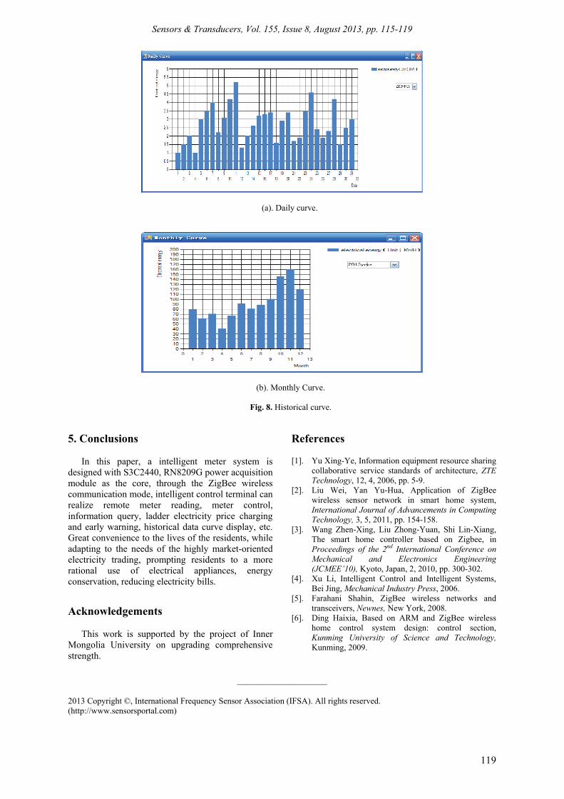
The function of historical curve section is to analyze the user's historical data in the form of a histogram, including daily curve and monthly curve as shown in Fig. 8 (a, b).
Sensors & Transducers, Vol. 155, Issue 8, August 2013, pp. 115-119
119
(a). Daily curve.
(b). Monthly Curve.
Fig. 8. Historical curve.
5. Conclusions In this paper, a intelligent meter system is
designed with S3C2440, RN8209G power acquisition module as the core, through the ZigBee wireless communication mode, intelligent control terminal can realize remote meter reading, meter control, information query, ladder electricity price charging and early warning, historical data curve display, etc. Great convenience to the lives of the residents, while adapting to the needs of the highly market-oriented electricity trading, prompting residents to a more rational use of electrical appliances, energy conservation, reducing electricity bills.
Acknowledgements
This work is supported by the project of Inner Mongolia University on upgrading comprehensive strength.
References [1]. Yu Xing-Ye, Information equipment resource sharing
collaborative service standards of architecture, ZTE Technology, 12, 4, 2006, pp. 5-9.
[2]. Liu Wei, Yan Yu-Hua, Application of ZigBee wireless sensor network in smart home system, International Journal of Advancements in Computing Technology, 3, 5, 2011, pp. 154-158.
[3]. Wang Zhen-Xing, Liu Zhong-Yuan, Shi Lin-Xiang, The smart home controller based on Zigbee, in Proceedings of the 2nd International Conference on Mechanical and Electronics Engineering (JCMEE’10), Kyoto, Japan, 2, 2010, pp. 300-302.
[4]. Xu Li, Intelligent Control and Intelligent Systems, Bei Jing, Mechanical Industry Press, 2006.
[5]. Farahani Shahin, ZigBee wireless networks and transceivers, Newnes, New York, 2008.
[6]. Ding Haixia, Based on ARM and ZigBee wireless home control system design: control section, Kunming University of Science and Technology, Kunming, 2009.
___________________
2013 Copyright ©, International Frequency Sensor Association (IFSA). All rights reserved. (http://www.sensorsportal.com)